Embed Size (px)
Citation preview
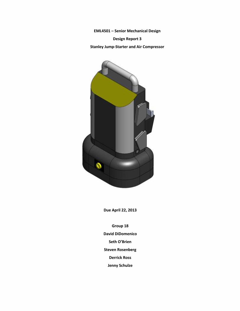
EML4501 – Senior Mechanical Design
Design Report 3
Stanley Jump-Starter and Air Compressor
Due April 22, 2013
Group 18
David DiDomenico
Seth O’Brien
Steven Rosenberg
Derrick Ross
Jenny Schulze

Table of Contents Introduction…………………………………………………………………………………………………………………………………………….3
Functional Requirements…………………………………………………………………………………………………………………………3
Product Specifications……………………………………………………………………………………………………………………………..3
Operational Procedure…………………………………………………………………………………………………………………………….7
Part Descriptions……………………………………………………………………………………………………………………………………10
Modular Unit Specifications……………………………………………………………………………………………………………………71
Pressure Controller Specifications………………………………………………………………………………………………………….74
Motor/Compressor Analysis..………………………………………………………………………………………………………………..91
Assembly……………………………………………………………………………………………………………………………………………….98
Cost Analysis………………………………………………………………………………………………………………………………………..156
Circuits…………………………………………………………………………………………………………………………………………………170
Safety…………………………………………………………………………………………………………………………………………………..172
Conclusion…………………………………………………………………………………………………………………………………………..173
Appendix A - Part Drawings………………………………………………………………………………………………………………….174
Appendix B – Closure Equations…………………………………………………………………………………………………………..195
Appendix C – References………………………………………………………………………………………………………………………203
Appendix D – Assembly Charts……………………………………………………………………………………………………………..206
Appendix E – Plastic Identification Chart………………………………………………………………………………………………208
3
Introduction This report focuses on the design and analysis of a portable jump start and air compressor unit that is
capable of working on any vehicle ranging from a small riding lawn mower, all the way up to a tractor
trailer. The scope of the analysis in this report includes, but is not limited to: fluid mechanics, heat
transfer, Von Mises stress analysis, materials, life analysis, friction, and expansion. The goal of this study
is to effectively design a system that has a wide range of functionality and is within a very reasonable
price range for mass production.
Functional Requirements The jump starting unit will need to meet several functional requirements.
Compressor Controller
A compressor controller must be designed such that its functionality meets or surpasses the ability to fill
four evenly exhausted tires, in succession, to a user defined pressure. All tires must be filled within the
same amount of time.
Use on Tractor Trailer
The jump starting system must be fully capable of functioning on a tractor trailer. The compressor must
also be able to fill tractor trailer tires in a reasonable amount of time.
Product Manufacturing
The product must be “Made in America.” This significantly increases the manufacturing and assembly
costs as the minimum wage is increased from ~$1.50/hr overseas, to $20.00/hr.
Product Cost
The product must sell for $150.00 with a 25% mark-up. This leaves $112.50 for total cost of creation.
Product Specifications The Jump-Starter 2000 should combine a jump-starter, air compressor, emergency LED light, USB port,
12 V DC charger into a single unit. The unit should be small enough to be carried in the trunk of a small
car or toolbox of a pickup truck. The tool should be designed such that no harm or injury comes to the
user under any circumstances, and so that no damage to the user’s vehicle occurs during normal use.
The tool should be designed and constructed such that no part will break, undergo significant wear, or
fail under normal appropriate use. The design and material selection, as well as the manufacturing
process, should emphasize cost effectiveness while fulfilling the functional requirements listed below for
each individual function. In many cases, it might be more cost effective to purchase components off the
shelf rather than manufacture them; this is acceptable as long as the functional requirements are met.
4
Jump-Starter
The jump-starter feature of the unit is, as the unit name suggests, the most important feature and that
which the entire unit is built around. Usually, when a vehicle battery “dies” (or is discharged to the
point that it is no longer able to crank the engine) the user “jump-starts” the vehicle by connecting a
working car battery in another vehicle to the “dead” vehicle’s electrical system. However, the jump-
starter system allows the user to start the dead vehicle without another vehicle present, by using the
charge in a smaller, more portable battery. This system must be able to jump-start vehicles ranging in
size from a small lawn mower, to a tractor trailer.
Most vehicles run off of a 12 V power supply. In order for the jump-starter to be effective, the jump-
starter battery must be able to provide at least 300 amps (A) at 12 V for five seconds, based on average
original equipment manufacturer (OEM) cranking amperage requirements. Most vehicles pull between
200 and 350 A during cranking at room temperature, however as temperature decreases, cranking
requirements increase exponentially. This is because not only does battery performance decrease as
temperature increases, but the cranking power of the starter must increase due to the increased
viscosity of engine fluids at lower temperatures. This has led to a common rating for cold cranking amps
(CCA) in the automobile battery industry, which is the maximum current the battery is able to maintain
for 30 seconds at a temperature of 0F. Most high-quality automobile batteries have CCA ratings
upwards of 600 A. However, the jump-starter is an emergency tool and must be portable and meet the
requirements for use in a normal operating environment, thus the requirements are not as high as those
for an automobile battery, which must be able to crank the vehicle under any condition.
A 24 V system is used to power tractor trailers. This means that a standard 12 V battery jump starter
would not be sufficient for turning over the starter. In addition to the higher voltage power source,
tractor trailers require a much higher amperage input to power the starter. A standard tractor trailer
requires 600 cranking amps to be maintained for 5 seconds in order to turn over the engine. By
connecting two of the aforementioned batteries in series we can achieve a 24 volt output with 2000
peak amps and 600 amps sustained for 5 seconds. This sufficiently meets the requirements for jump-
starting a tractor trailer.
5
Car batteries are also designed to provide power to auxiliary features within the car while the engine is
off; therefore they have large capacities, typically between 30-40 amp-hours (Ah), with some above 60
Ah. This correlates roughly to a reserve capacity (another industry-standard rating describing the length
of time the battery is able to provide 25 A before its voltage drops below 10.5 V) of one to two hours.
However, the jump-start battery is designed to crank a vehicle under emergency conditions and not run
auxiliary functions on the vehicle, so it requires less capacity than a standard automobile battery. With
this in mind, no specific capacity requirement applies to the jump-starter battery to provide auxiliary
power, however it should provide enough capacity to allow the user to crank the engine at least five
times in case it doesn’t start on the first try. Assuming an average crank time of one second, this should
correlate roughly to a five-second discharge at the required current output.
In addition to the battery, the jump-starter must include cables to connect the battery to the vehicle’s
electrical system. The cables should be similar in design to standard jumper cables, with large alligator
clips (color-coded black and red for negative and positive) on the end of each cable to connect to both
terminals of the car battery. The cables should be at least six feet long to allow them to reach the
battery while the unit sits on the ground next to the vehicle. The cable size should be large enough to
safely transmit the design current at 12 and 24 volts.
Air Compressor
The air compressor allows the user to add air to any desired object with a Schrader valve. The system
should consist of an electrically driven compressor, a hose with a Schrader valve adapter to deliver air to
the tire, a pressure regulator (to control desired pressure), and a gauge displaying the tire pressure.
The compressor should be internal to the unit, and should be a positive-displacement type compressor
with an electric motor driven from the main battery used in the jump-starter system. The system should
be designed to produce at least 120 psi, since some smaller applications like bicycle tires routinely
require such high pressure. The flow rate should be sufficient enough to inflate an average SUV tire in
less than five minutes, and a tractor trailer tire within 15 minutes. With these design requirements in
mind, the system and motor should be sized for the minimum current draw, so the user can fill all four
tires of a vehicle on a singular battery charge.
6
Noise level of the compressor is not a design requirement, since the unit will most likely be used on the
side of a busy road.
In addition to the motor/compressor system inside the overall unit, the compressor outlet should be
attached to an external air hose at least six feet in length so the user can fill any tire with the unit resting
on the ground. The hose should have a Schrader valve adapter on the end with a clamp so that no air
flows unless the hose is clamped onto the valve stem. Any attachments should be able to be clamped
into the same mechanism for use.
The pressure gauge should be linked to the system at any point downstream of the compressor outlet
and should be mounted on the outside of the overall unit. The gauge should have a clearly marked scale
with both metric and U.S. standard pressure markings around the outside, with a resolution of at least
2.5 psi and 0.5 bar.
The air compressor system also contains a pressure regulator that gives the user the ability to set a
target pressure. Once the desired pressure is set, the compressor will inflate the object to that pressure.
When the target pressure is reached, the regulator trips an electrical connector which shuts off the
compressor and will not fill up the object any longer. The user can fine tune the desired pressure by
tightening or loosening the fastener at the top of the regulator. When the fastener is completely backed
out, the target pressure is zero psi. Each full turn of the fastener will increase the target pressure by 20
psi. The fill time for an 18 L (tractor trailer) tire from 0 psi to 120 psi is 15 minutes. Therefore, it is safe to
assume that all wheels will take less than or equal to 15 minutes to fill.
USB charging outlet
The USB charging outlet allows the user to charge any device with a USB-type charging cable. The outlet
should be a standard USB port with power connections and no data connections. The port should
provide the standard 5 V DC signal at a current of no less than 500 mA. This is the minimum allowable
current for a Dedicated Charging Port according to the USB Battery Charging Specification of 2007.
12 V DC charging outlet
7
The 12 V DC outlet is used to charge peripheral devices such as cell phone and music players. The outlet
should be the standard cigarette lighter type outlet, providing a current of at least 5 A in order to charge
a variety of devices.
The unit should also be able to receive a charge using the 12 V DC outlet. This will require a cord with a
charging plug on both ends so the user can connect the unit to the vehicle’s 12 V DC charging port.
Flashlight
The flashlight should be an LED light to minimize the current draw on the battery, and should be
movable so that the user can direct the light in the desired direction without moving the entire unit.
12 – 24 Volt Functionality
The device should be capable of switching between a 12 and 24 V power supply. When the unit is in the
24 V mode, the 12 V circuit board should be bypassed by one of the batteries as to ensure not to burn
up the circuit board.
Other Requirements
The unit should have a standard 110 V charging plug so the user can charge the unit using a standard
extension cord. The electrical system should have the circuitry necessary to allow the user to leave the
unit plugged in without over-charging and damaging the battery. Appropriate switches should be used
for each function to ensure no current is flowing when not in use, and to prevent accidental shock.
There should also be a battery capacity meter that clearly displays the battery’s state of charge.
In order to prevent fire and severe damage to one or both batteries, the unit should have a polarity light
that displays whether the jumper cables are attached to the correct battery terminals before the
batteries are connected electrically.
The complete unit should be as compact as possible and have a handle for the user to carry the unit
easily. The outside should be rugged enough to withstand normal wear and tear and protect the
internals such as the compressor, battery, and circuitry from impact.

8
Operational Procedure This product has many functions for various applications. There are two main features of this product,
the jump-starter, and the air compressor.
Charging the Unit
The unit can be charged in two different ways. The first option is to use the 12 Volt DC outlet. The
system comes with a double sided 12 volt DC accessory outlet. NOTE: This method can lead to
overcharging of the battery. For this reason, do not leave the unit alone when charging with this
method.
1. Insert the gold-tipped 12 volt DC charging adapter plug into the vehicle’s 12 volt DC accessory outlet.
2. Insert the silver-tipped end plug into the 12 volt DC accessory outlet on the front panel of the unit.
3. Charge the unit until the green FULL indicator is lit up (will occur when the “Battery Power Level” button is pressed)
4. Remove charging cords.
The other option for charging the unit is using the 120 volt AC charger and a standard, self-supplied,
extension cord. NOTE: This method cannot overcharge the battery.
1. Lift the AC adapter cover on the back of the unit and connect the extension cord to the unit. Plug the other end of the extension cord into a 120 volt wall outlet.
2. Charge the unit until the green FULL indicator is lit up (will occur when the “Battery Power Level” button is pressed)
3. Remove charging cords.
Jump-Starter
The jump start system is extremely user friendly. There are two components to this system. The first
component is the Main unit. The main unit contains everything necessary to jumpstart vehicles ranging
in size from a small lawn mower, to a full size pickup truck. The optional modular battery pack provides
the user with the ability to jumpstart any vehicle up to a tractor trailer. The jump-starting process is
extremely simple, but can very easily cause damage if done incorrectly. Please follow the following
procedure when jump-starting any vehicle.
1. Verify that the battery in your vehicle is actually dead and this is the reason that you are unable to start your vehicle. If you determine another possible cause for the problem, please contact your vehicle manufacturer as soon as possible to determine the necessary course of action. If you are unsure of the actual issue, please seek expert advice.
2. Locate the battery in your vehicle. The battery is generally under the hood, near the front of the vehicle. See your vehicle manual if you are unable to locate your battery. If necessary, remove any caps that may be covering the positive and negative terminals on the battery.
3. Identify the positive and negative terminals
9
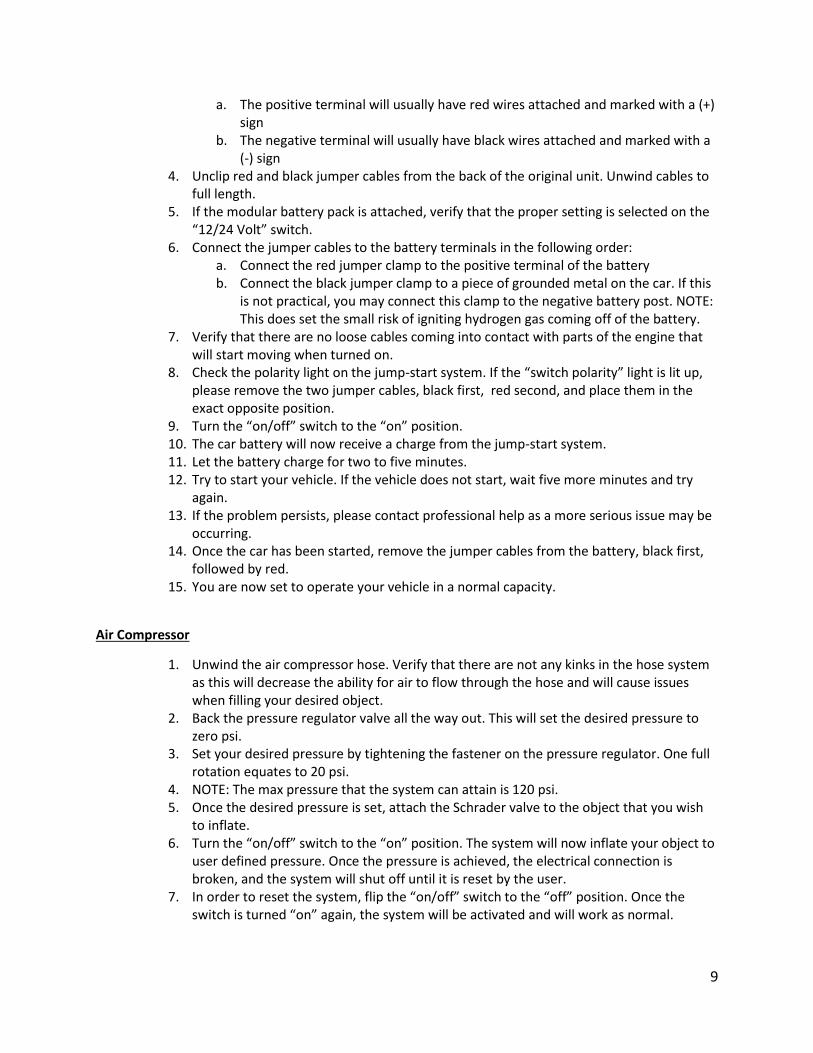
a. The positive terminal will usually have red wires attached and marked with a (+) sign
b. The negative terminal will usually have black wires attached and marked with a (-) sign
4. Unclip red and black jumper cables from the back of the original unit. Unwind cables to full length.
5. If the modular battery pack is attached, verify that the proper setting is selected on the “12/24 Volt” switch.
6. Connect the jumper cables to the battery terminals in the following order: a. Connect the red jumper clamp to the positive terminal of the battery b. Connect the black jumper clamp to a piece of grounded metal on the car. If this
is not practical, you may connect this clamp to the negative battery post. NOTE: This does set the small risk of igniting hydrogen gas coming off of the battery.
7. Verify that there are no loose cables coming into contact with parts of the engine that will start moving when turned on.
8. Check the polarity light on the jump-start system. If the “switch polarity” light is lit up, please remove the two jumper cables, black first, red second, and place them in the exact opposite position.
9. Turn the “on/off” switch to the “on” position. 10. The car battery will now receive a charge from the jump-start system. 11. Let the battery charge for two to five minutes. 12. Try to start your vehicle. If the vehicle does not start, wait five more minutes and try
again. 13. If the problem persists, please contact professional help as a more serious issue may be
occurring. 14. Once the car has been started, remove the jumper cables from the battery, black first,
followed by red. 15. You are now set to operate your vehicle in a normal capacity.
Air Compressor
1. Unwind the air compressor hose. Verify that there are not any kinks in the hose system as this will decrease the ability for air to flow through the hose and will cause issues when filling your desired object.
2. Back the pressure regulator valve all the way out. This will set the desired pressure to zero psi.
3. Set your desired pressure by tightening the fastener on the pressure regulator. One full rotation equates to 20 psi.
4. NOTE: The max pressure that the system can attain is 120 psi. 5. Once the desired pressure is set, attach the Schrader valve to the object that you wish
to inflate. 6. Turn the “on/off” switch to the “on” position. The system will now inflate your object to
user defined pressure. Once the pressure is achieved, the electrical connection is broken, and the system will shut off until it is reset by the user.
7. In order to reset the system, flip the “on/off” switch to the “off” position. Once the switch is turned “on” again, the system will be activated and will work as normal.
10
8. Repeat the process as necessary. NOTE: If you desire to change the “fill to” pressure, back the fastener all the way out and tighten down for as many rotations as necessary to set to the newly desired pressure. One full rotation equates to 20 psi.
USB Power Port
1. Push the USB Power Button to turn on the USB Port. The USB power indicator will light up.
2. Lift the USB port cover. 3. Plug in the USB-powered device and operate device as usual.
Emergency Area Light
The light can be used in any low light situation as necessary for the user. A switch is located on top of
the light. Make sure that the light is kept off when not in use. Leaving the light on will slowly drain the
battery.
12 Volt DC Portable Power Supply
This portable power source is also for use with all 12 volt DC accessories equipped with a male accessory
outlet plug and are rated up to 5 amps.
1. Lift up the cover of the unit‘s 12 volt DC outlet. 2. Insert the 12 volt DC plug from the appliance into the 12 volt accessory outlet on the
unit. DO NOT EXCEED A 5 AMP LOAD. 3. Switch on the appliance and operate as usual. 4. Periodically press the battery charge level pushbutton to check battery status.
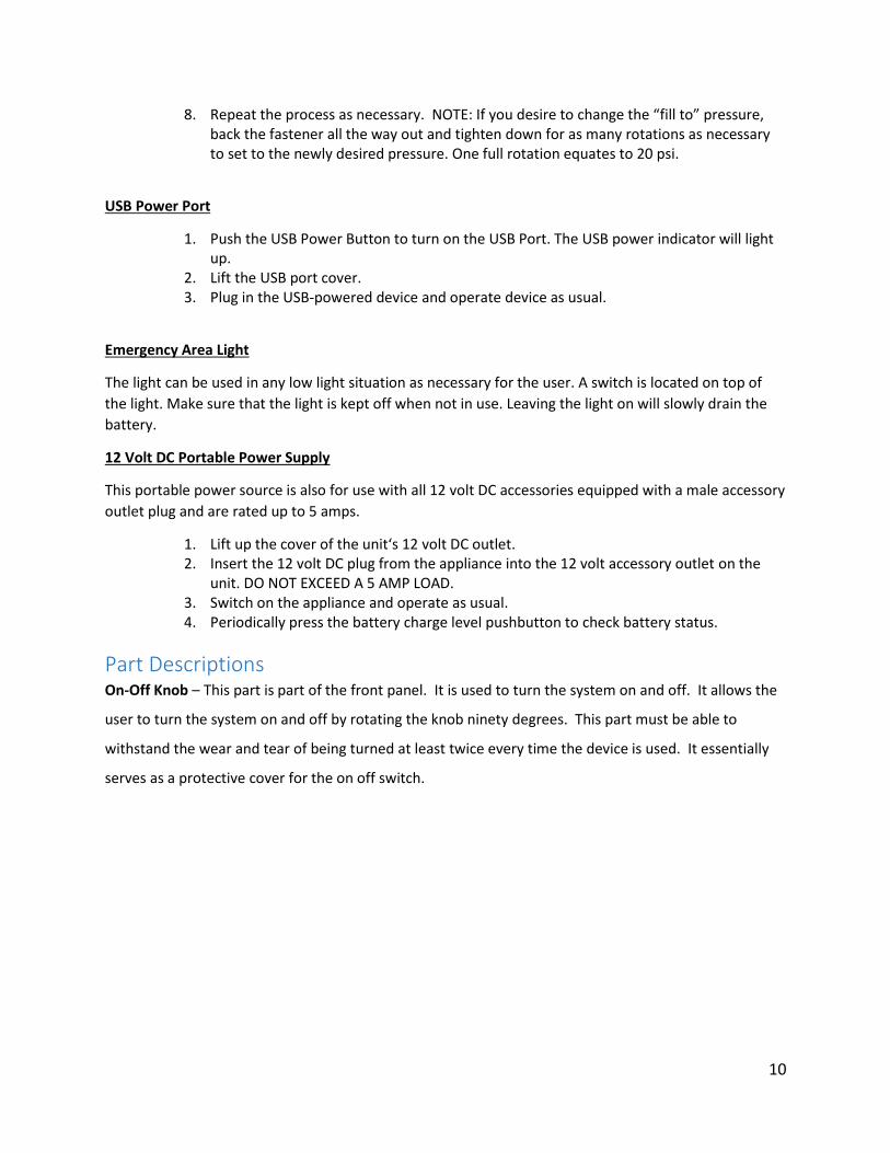
Part Descriptions On-Off Knob – This part is part of the front panel. It is used to turn the system on and off. It allows the
user to turn the system on and off by rotating the knob ninety degrees. This part must be able to
withstand the wear and tear of being turned at least twice every time the device is used. It essentially
serves as a protective cover for the on off switch.
11
Fig. 1 – On/Off Knob
Manufacturing Technique- This part was created using injection molding. Plastic testing was performed
in order to determine the type of material. When a soldering iron was pressed to the material it
softened. When a piece was placed in water it sank. A sample was burned. It continued to burn and
dripped. It produced a blue flame with yellow edges, black smoke and soot. It burned slow and smelled
acrid. This means it is made of Acrylonitrile Butadiene Styrene. Injection molding was chosen because it
is easy to perform when mass producing the device. It allows for a quick production with low
production cost.
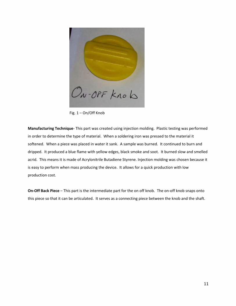
On-Off Back Piece – This part is the intermediate part for the on off knob. The on-off knob snaps onto
this piece so that it can be articulated. It serves as a connecting piece between the knob and the shaft.
12
Fig. 2 – On/Off Backpiece
Manufacturing Technique – This piece was injection molded. A plastic test was performed to determine
the material type. It softened when a soldering iron was pressed to it. When it was placed in water it
sank. A sample was then burned. The sample self-extinguished. The test results show that it is made of
polyphenylene ether. This production technique was selected because it allowed for the part to be
made fast and cheaply.
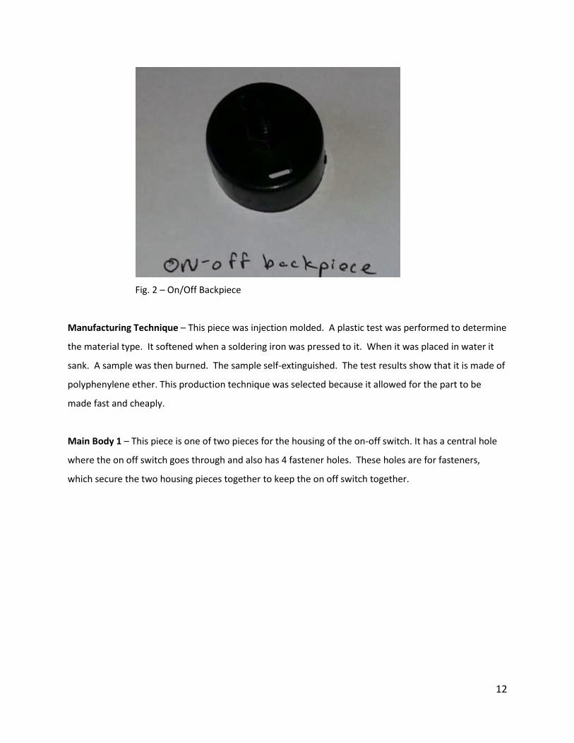
Main Body 1 – This piece is one of two pieces for the housing of the on-off switch. It has a central hole
where the on off switch goes through and also has 4 fastener holes. These holes are for fasteners,
which secure the two housing pieces together to keep the on off switch together.
13
Fig. 3 – Main Body 1
Manufacturing Technique- This piece was created by injection molding. Plastic testing was conducted
to determine the material type. When a soldering iron was applied to the material it softens. When a
sample was placed in water it sank. When an attempt was made to burn the sample it self-extinguished.
These results mean it was made out of polyphenylene ether. This piece was created by injection
molding because it allows for the piece to be made quickly and efficiently.
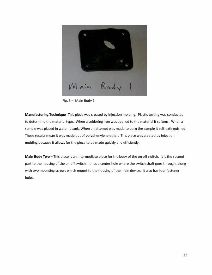
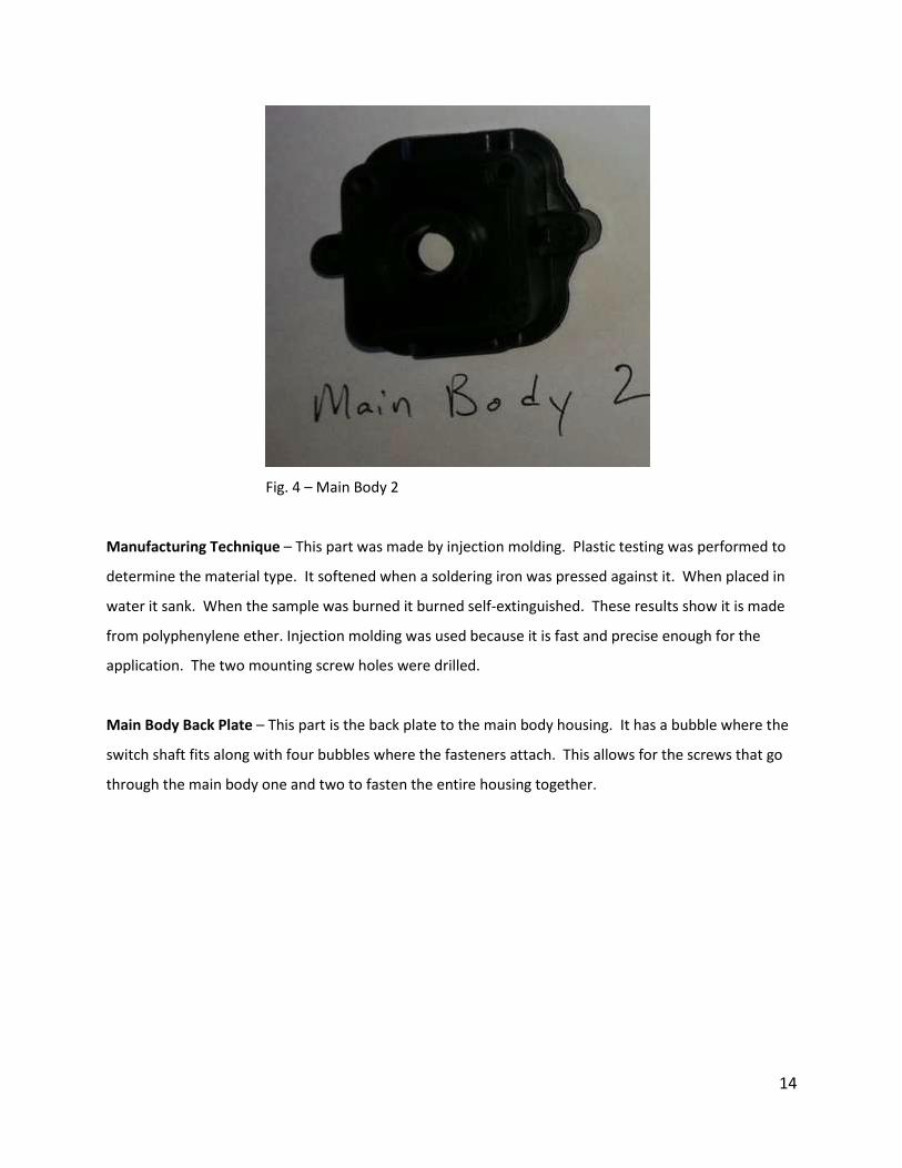
Main Body Two – This piece is an intermediate piece for the body of the on off switch. It is the second
part to the housing of the on off switch. It has a center hole where the switch shaft goes through, along
with two mounting screws which mount to the housing of the main device. It also has four fastener
holes.
14
Fig. 4 – Main Body 2
Manufacturing Technique – This part was made by injection molding. Plastic testing was performed to
determine the material type. It softened when a soldering iron was pressed against it. When placed in
water it sank. When the sample was burned it burned self-extinguished. These results show it is made
from polyphenylene ether. Injection molding was used because it is fast and precise enough for the
application. The two mounting screw holes were drilled.
Main Body Back Plate – This part is the back plate to the main body housing. It has a bubble where the
switch shaft fits along with four bubbles where the fasteners attach. This allows for the screws that go
through the main body one and two to fasten the entire housing together.

15
Fig. 5 – Main Body Back Plate
Manufacturing Technique – Injection molding was used to produce this part. Plastic identification tests
were conducted to determine what the part was made of. When a soldering iron was placed on it, it
melted. When placed in water, the sample sank. When burned, it did not melt and self-extinguished.
This means the part was made out of polyphenylene ether. Injection molding was selected because it
allows for the part to be produced fast and for a low price. The holes for the fasteners were drilled.
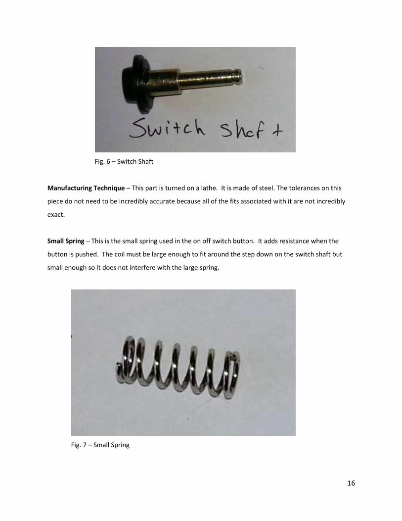
Switch Shaft – The switch shaft is the part that the On-Off knob articulates. It turns within the main
body housing and turns on the system. It is housed within the main body and has two different springs
that go around the shaft. It has a large head on it, which pins the large spring between the metal plate
and the shaft. It also has a step-down on the shaft where the small spring is held.
16
Fig. 6 – Switch Shaft
Manufacturing Technique – This part is turned on a lathe. It is made of steel. The tolerances on this
piece do not need to be incredibly accurate because all of the fits associated with it are not incredibly
exact.
Small Spring – This is the small spring used in the on off switch button. It adds resistance when the
button is pushed. The coil must be large enough to fit around the step down on the switch shaft but
small enough so it does not interfere with the large spring.
Fig. 7 – Small Spring
17
Manufacturing Techniques – the wire stock is drawn into rods and then the spring is formed through
mechanical deformation of the wire. It was determined that the spring is made from steel.
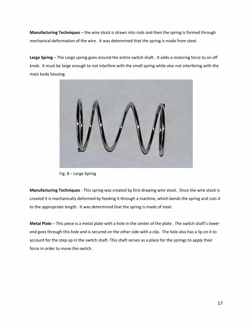
Large Spring – The Large spring goes around the entire switch shaft. It adds a restoring force to on off
knob. It must be large enough to not interfere with the small spring while also not interfering with the
main body housing.
Fig. 8 – Large Spring
Manufacturing Techniques - This spring was created by first drawing wire stock. Once the wire stock is
created it is mechanically deformed by feeding it through a machine, which bends the spring and cuts it
to the appropriate length. It was determined that the spring is made of steel.
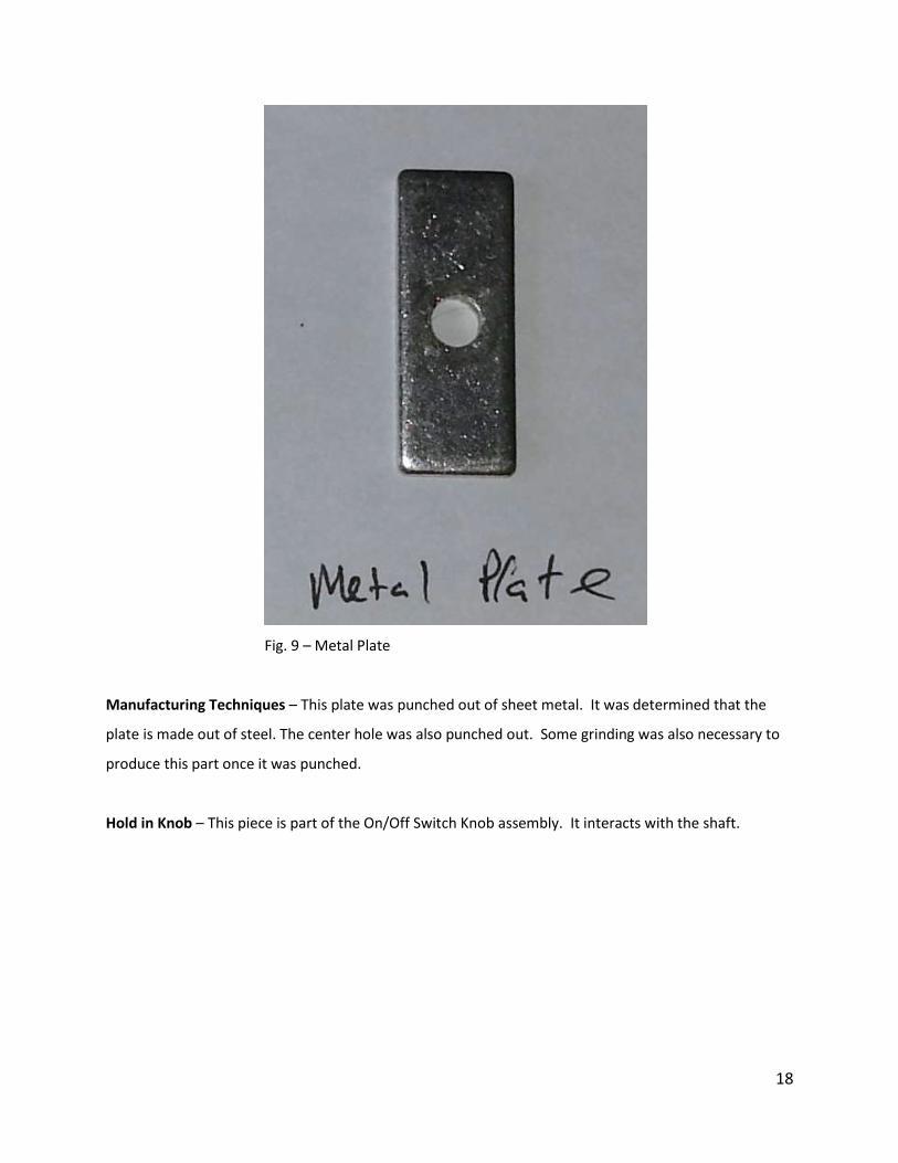
Metal Plate – This piece is a metal plate with a hole in the center of the plate. The switch shaft’s lower
end goes through this hole and is secured on the other side with a clip. The hole also has a lip on it to
account for the step up in the switch shaft. This shaft serves as a place for the springs to apply their
force in order to move the switch.
18
Fig. 9 – Metal Plate
Manufacturing Techniques – This plate was punched out of sheet metal. It was determined that the
plate is made out of steel. The center hole was also punched out. Some grinding was also necessary to
produce this part once it was punched.
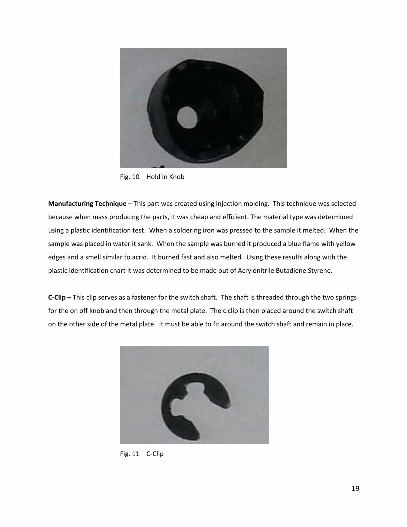
Hold in Knob – This piece is part of the On/Off Switch Knob assembly. It interacts with the shaft.
19
Fig. 10 – Hold in Knob
Manufacturing Technique – This part was created using injection molding. This technique was selected
because when mass producing the parts, it was cheap and efficient. The material type was determined
using a plastic identification test. When a soldering iron was pressed to the sample it melted. When the
sample was placed in water it sank. When the sample was burned it produced a blue flame with yellow
edges and a smell similar to acrid. It burned fast and also melted. Using these results along with the
plastic identification chart it was determined to be made out of Acrylonitrile Butadiene Styrene.
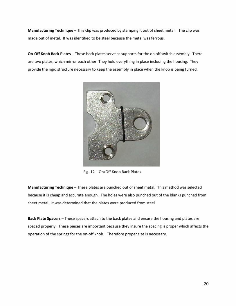
C-Clip – This clip serves as a fastener for the switch shaft. The shaft is threaded through the two springs
for the on off knob and then through the metal plate. The c clip is then placed around the switch shaft
on the other side of the metal plate. It must be able to fit around the switch shaft and remain in place.
Fig. 11 – C-Clip
20
Manufacturing Technique – This clip was produced by stamping it out of sheet metal. The clip was
made out of metal. It was identified to be steel because the metal was ferrous.
On-Off Knob Back Plates – These back plates serve as supports for the on off switch assembly. There
are two plates, which mirror each other. They hold everything in place including the housing. They
provide the rigid structure necessary to keep the assembly in place when the knob is being turned.
Fig. 12 – On/Off Knob Back Plates
Manufacturing Technique – These plates are punched out of sheet metal. This method was selected
because it is cheap and accurate enough. The holes were also punched out of the blanks punched from
sheet metal. It was determined that the plates were produced from steel.
Back Plate Spacers – These spacers attach to the back plates and ensure the housing and plates are
spaced properly. These pieces are important because they insure the spacing is proper which affects the
operation of the springs for the on-off knob. Therefore proper size is necessary.

21
Fig. 13 – Back Plate Spacer
Manufacturing Technique – These spacers are made of an unknown composite. When a plastic
identification test was performed, an outside layer burned exposing some form of matrix. This shows
that it is made of some form of composite.
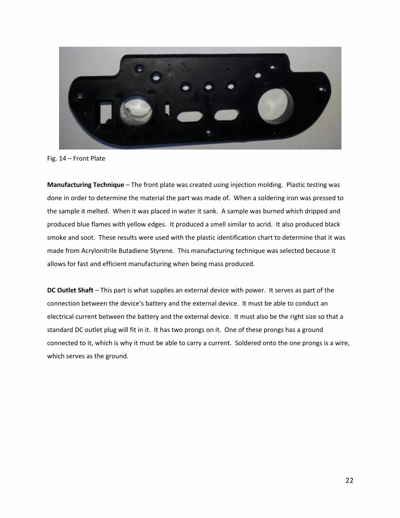
Front Plate – The front plate serves as the housing for all the interfaces for the device. It houses the
lights, buttons, and inputs for the device. The indicators include a light to show the USB port is on, a
light to display if the polarity of the battery is reversed, and three lights on the front to display the
charge status of the battery; two are red for low to medium and one is green to signify a high charge.
There are two buttons; one to use when assessing the battery status and one to power the USB port.
Lastly there is the large On-Off knob and a cover for the USB port and DC outlet.
22
Fig. 14 – Front Plate
Manufacturing Technique – The front plate was created using injection molding. Plastic testing was
done in order to determine the material the part was made of. When a soldering iron was pressed to
the sample it melted. When it was placed in water it sank. A sample was burned which dripped and
produced blue flames with yellow edges. It produced a smell similar to acrid. It also produced black
smoke and soot. These results were used with the plastic identification chart to determine that it was
made from Acrylonitrile Butadiene Styrene. This manufacturing technique was selected because it
allows for fast and efficient manufacturing when being mass produced.
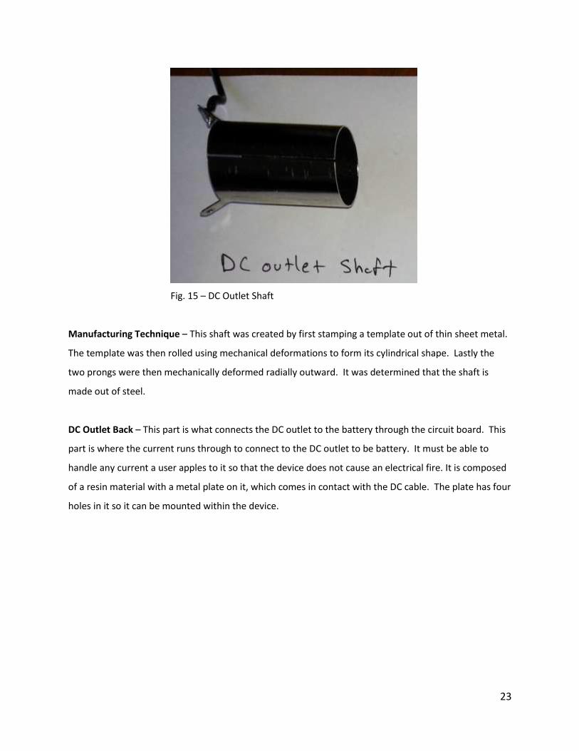
DC Outlet Shaft – This part is what supplies an external device with power. It serves as part of the
connection between the device’s battery and the external device. It must be able to conduct an
electrical current between the battery and the external device. It must also be the right size so that a
standard DC outlet plug will fit in it. It has two prongs on it. One of these prongs has a ground
connected to it, which is why it must be able to carry a current. Soldered onto the one prongs is a wire,
which serves as the ground.
23
Fig. 15 – DC Outlet Shaft
Manufacturing Technique – This shaft was created by first stamping a template out of thin sheet metal.
The template was then rolled using mechanical deformations to form its cylindrical shape. Lastly the
two prongs were then mechanically deformed radially outward. It was determined that the shaft is
made out of steel.
DC Outlet Back – This part is what connects the DC outlet to the battery through the circuit board. This
part is where the current runs through to connect to the DC outlet to be battery. It must be able to
handle any current a user apples to it so that the device does not cause an electrical fire. It is composed
of a resin material with a metal plate on it, which comes in contact with the DC cable. The plate has four
holes in it so it can be mounted within the device.

24
Fig. 16 – DC Outlet Back
Manufacturing Technique – This part has numerous materials. The first is the circuit board. It was
determined that it is made of a resin that was insulated. The second part is the actual connection that
the DC cable connects to. It was determined to be made out of steel and was stamped from sheet
metal.
DC/USB Cover – This part is required to protect the DC and USB outlets on the device. It has one end
that snaps into place over the DC and USB outlets and the other end has a tab, which remains within the
device so that the cover stays attached to the device when it is removed from the outlets.
Fig. 17 – DC/USB Cover
25
Manufacturing Technique – This part was created using injection molding. It allowed for the part to be
mass produced cheaply and efficiently. Plastic identification was performed to determine the material
type of the part. When a soldering iron was pressed to the material it melted. When a sample was
placed in water it sank. The sample was then burned. When it was burned it continued to burn when
the flame was removed and dripped. It produced blue flames with yellow edges, smelled acrid, and
black smoke with soot. These results mean the part was made from Acrylonitrile Butadiene Styrene.
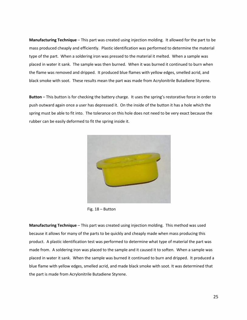
Button – This button is for checking the battery charge. It uses the spring’s restorative force in order to
push outward again once a user has depressed it. On the inside of the button it has a hole which the
spring must be able to fit into. The tolerance on this hole does not need to be very exact because the
rubber can be easily deformed to fit the spring inside it.
Fig. 18 – Button
Manufacturing Technique – This part was created using injection molding. This method was used
because it allows for many of the parts to be quickly and cheaply made when mass producing this
product. A plastic identification test was performed to determine what type of material the part was
made from. A soldering iron was placed to the sample and it caused it to soften. When a sample was
placed in water it sank. When the sample was burned it continued to burn and dripped. It produced a
blue flame with yellow edges, smelled acrid, and made black smoke with soot. It was determined that
the part is made from Acrylonitrile Butadiene Styrene.
26
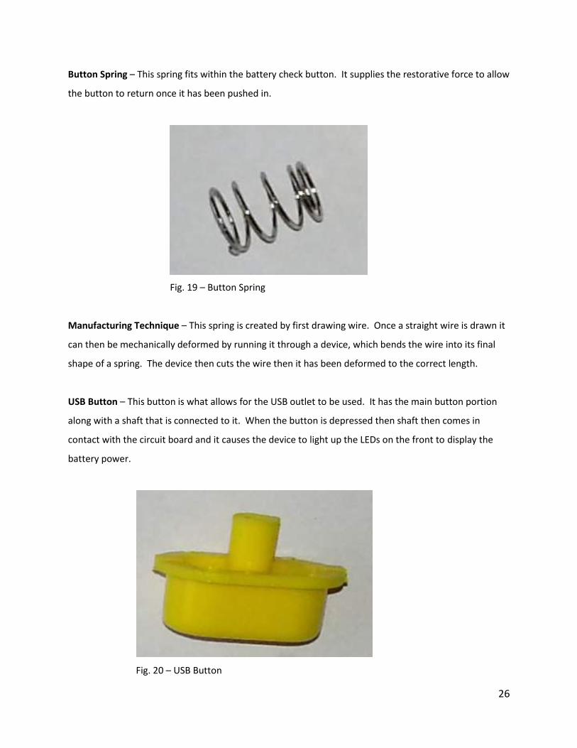
Button Spring – This spring fits within the battery check button. It supplies the restorative force to allow
the button to return once it has been pushed in.
Fig. 19 – Button Spring
Manufacturing Technique – This spring is created by first drawing wire. Once a straight wire is drawn it
can then be mechanically deformed by running it through a device, which bends the wire into its final
shape of a spring. The device then cuts the wire then it has been deformed to the correct length.
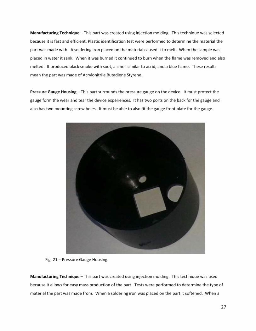
USB Button – This button is what allows for the USB outlet to be used. It has the main button portion
along with a shaft that is connected to it. When the button is depressed then shaft then comes in
contact with the circuit board and it causes the device to light up the LEDs on the front to display the
battery power.
Fig. 20 – USB Button
27
Manufacturing Technique – This part was created using injection molding. This technique was selected
because it is fast and efficient. Plastic identification test were performed to determine the material the
part was made with. A soldering iron placed on the material caused it to melt. When the sample was
placed in water it sank. When it was burned it continued to burn when the flame was removed and also
melted. It produced black smoke with soot, a smell similar to acrid, and a blue flame. These results
mean the part was made of Acrylonitrile Butadiene Styrene.
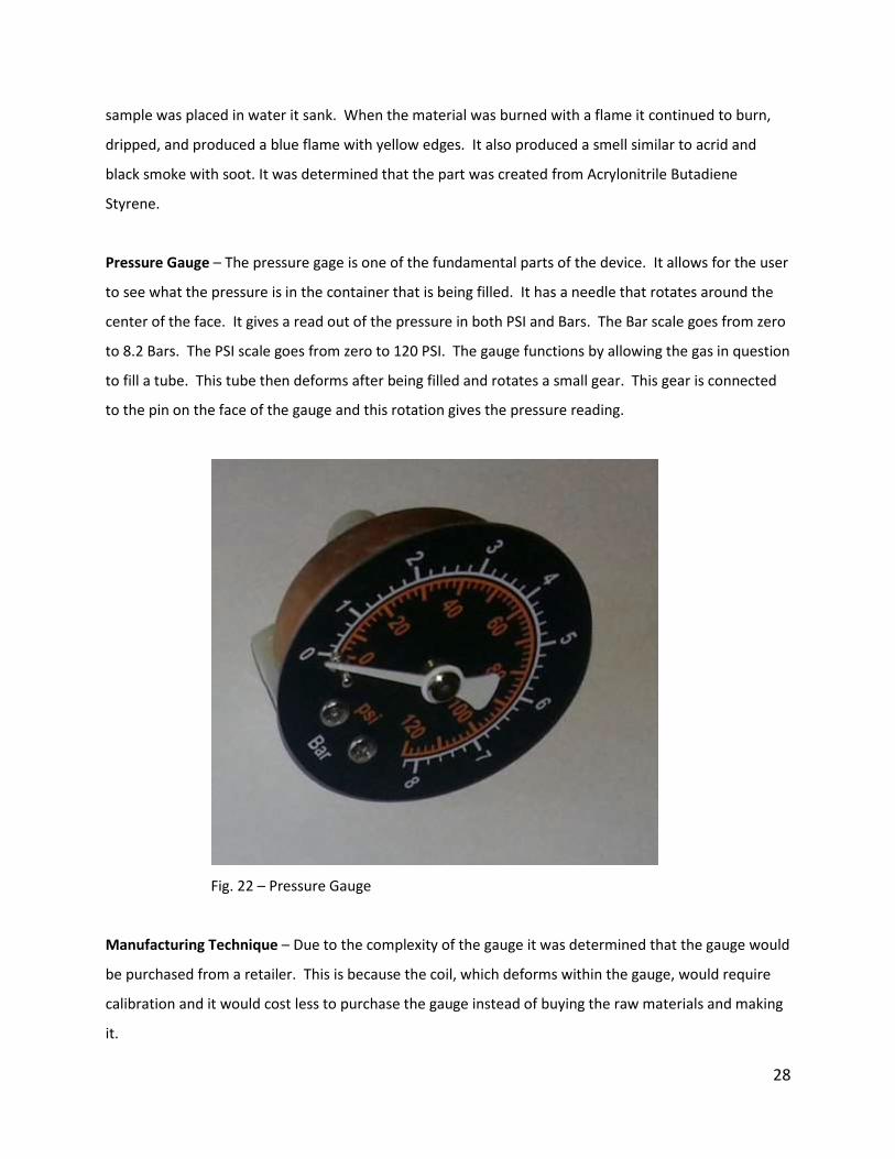
Pressure Gauge Housing – This part surrounds the pressure gauge on the device. It must protect the
gauge form the wear and tear the device experiences. It has two ports on the back for the gauge and
also has two mounting screw holes. It must be able to also fit the gauge front plate for the gauge.
Fig. 21 – Pressure Gauge Housing
Manufacturing Technique – This part was created using injection molding. This technique was used
because it allows for easy mass production of the part. Tests were performed to determine the type of
material the part was made from. When a soldering iron was placed on the part it softened. When a
28
sample was placed in water it sank. When the material was burned with a flame it continued to burn,
dripped, and produced a blue flame with yellow edges. It also produced a smell similar to acrid and
black smoke with soot. It was determined that the part was created from Acrylonitrile Butadiene
Styrene.
Pressure Gauge – The pressure gage is one of the fundamental parts of the device. It allows for the user
to see what the pressure is in the container that is being filled. It has a needle that rotates around the
center of the face. It gives a read out of the pressure in both PSI and Bars. The Bar scale goes from zero
to 8.2 Bars. The PSI scale goes from zero to 120 PSI. The gauge functions by allowing the gas in question
to fill a tube. This tube then deforms after being filled and rotates a small gear. This gear is connected
to the pin on the face of the gauge and this rotation gives the pressure reading.
Fig. 22 – Pressure Gauge
Manufacturing Technique – Due to the complexity of the gauge it was determined that the gauge would
be purchased from a retailer. This is because the coil, which deforms within the gauge, would require
calibration and it would cost less to purchase the gauge instead of buying the raw materials and making
it.
29
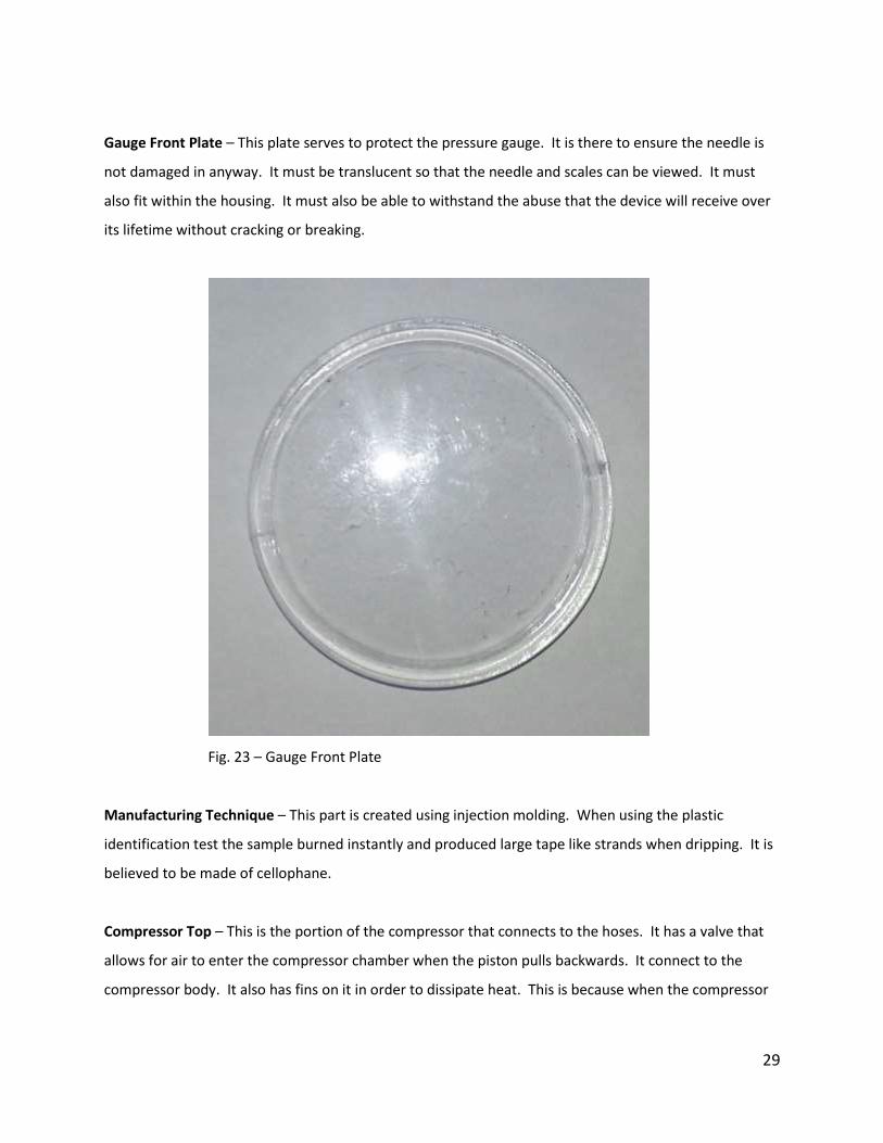
Gauge Front Plate – This plate serves to protect the pressure gauge. It is there to ensure the needle is
not damaged in anyway. It must be translucent so that the needle and scales can be viewed. It must
also fit within the housing. It must also be able to withstand the abuse that the device will receive over
its lifetime without cracking or breaking.
Fig. 23 – Gauge Front Plate
Manufacturing Technique – This part is created using injection molding. When using the plastic
identification test the sample burned instantly and produced large tape like strands when dripping. It is
believed to be made of cellophane.
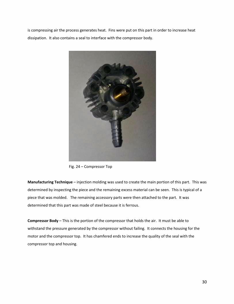
Compressor Top – This is the portion of the compressor that connects to the hoses. It has a valve that
allows for air to enter the compressor chamber when the piston pulls backwards. It connect to the
compressor body. It also has fins on it in order to dissipate heat. This is because when the compressor
30
is compressing air the process generates heat. Fins were put on this part in order to increase heat
dissipation. It also contains a seal to interface with the compressor body.
Fig. 24 – Compressor Top
Manufacturing Technique – injection molding was used to create the main portion of this part. This was
determined by inspecting the piece and the remaining excess material can be seen. This is typical of a
piece that was molded. The remaining accessory parts were then attached to the part. It was
determined that this part was made of steel because it is ferrous.
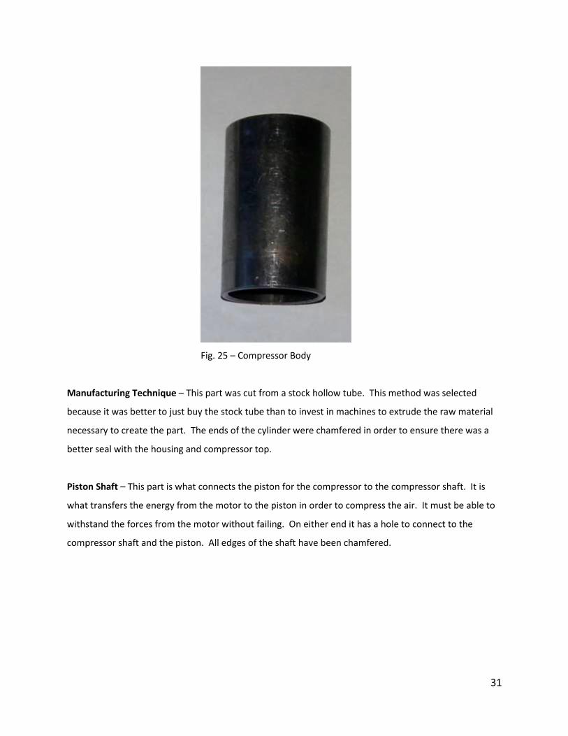
Compressor Body – This is the portion of the compressor that holds the air. It must be able to
withstand the pressure generated by the compressor without failing. It connects the housing for the
motor and the compressor top. It has chamfered ends to increase the quality of the seal with the
compressor top and housing.
31
Fig. 25 – Compressor Body
Manufacturing Technique – This part was cut from a stock hollow tube. This method was selected
because it was better to just buy the stock tube than to invest in machines to extrude the raw material
necessary to create the part. The ends of the cylinder were chamfered in order to ensure there was a
better seal with the housing and compressor top.
Piston Shaft – This part is what connects the piston for the compressor to the compressor shaft. It is
what transfers the energy from the motor to the piston in order to compress the air. It must be able to
withstand the forces from the motor without failing. On either end it has a hole to connect to the
compressor shaft and the piston. All edges of the shaft have been chamfered.

32
Fig. 26 –Piston Shaft
Manufacturing Technique – This part was manufactured out of steel. The manufacture started with raw
material and removed material until it met the required specifications. It was determined that the part
was made out of steel by seeing if the part was ferrous.
Piston – This is the part of the compressor that compresses the air. It is a cylindrical piece with an end
cap on it. This end cap secures a seal on the end of the piston. This seal is necessary to ensure the
volume of the compressor body is sealed. It slides back and forth within the compressor body.
Fig. 27 – Piston
33
Manufacturing Technique – This part was created through the use of casting. The seal and ring were
then placed onto the end of the piston. It was determined that the part was made of steel because the
part is ferrous.
Piston Pin – This is a pin that goes through the Piston and piston shaft. It kept the piston engaged with
the piston shaft. It serves as a fastener. There is no picture of the pin because it was destroyed while
disassembling the device.
Fig. 28 – CAD rendition of the piston pin (original was destroyed during disassembly)
Manufacturing Technique – This pin was created from bar stock. It was determined that the pin was
made of steel because it was ferrous.
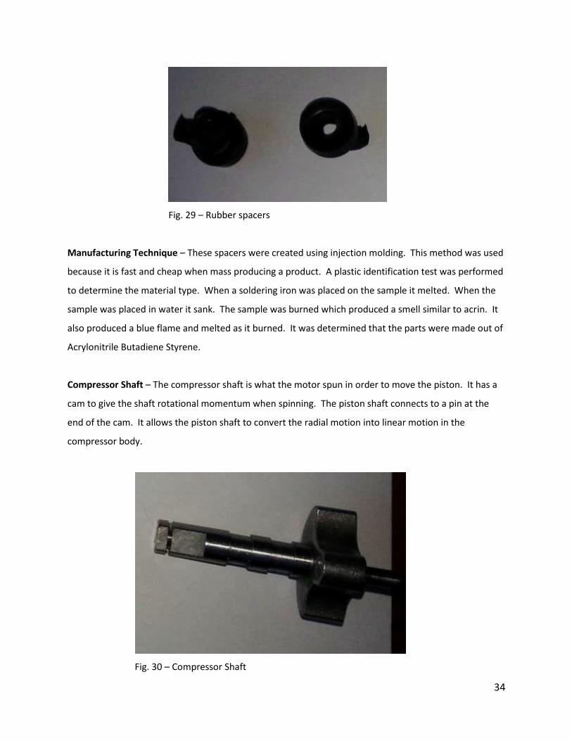
Rubber Spacers – These spacers went around the screws that secured the compressor within the main
housing of the device. Their main purpose was to act as a washer for the screws and to dampen the
vibrations created by the compressor when it compresses air.
34
Fig. 29 – Rubber spacers
Manufacturing Technique – These spacers were created using injection molding. This method was used
because it is fast and cheap when mass producing a product. A plastic identification test was performed
to determine the material type. When a soldering iron was placed on the sample it melted. When the
sample was placed in water it sank. The sample was burned which produced a smell similar to acrin. It
also produced a blue flame and melted as it burned. It was determined that the parts were made out of
Acrylonitrile Butadiene Styrene.
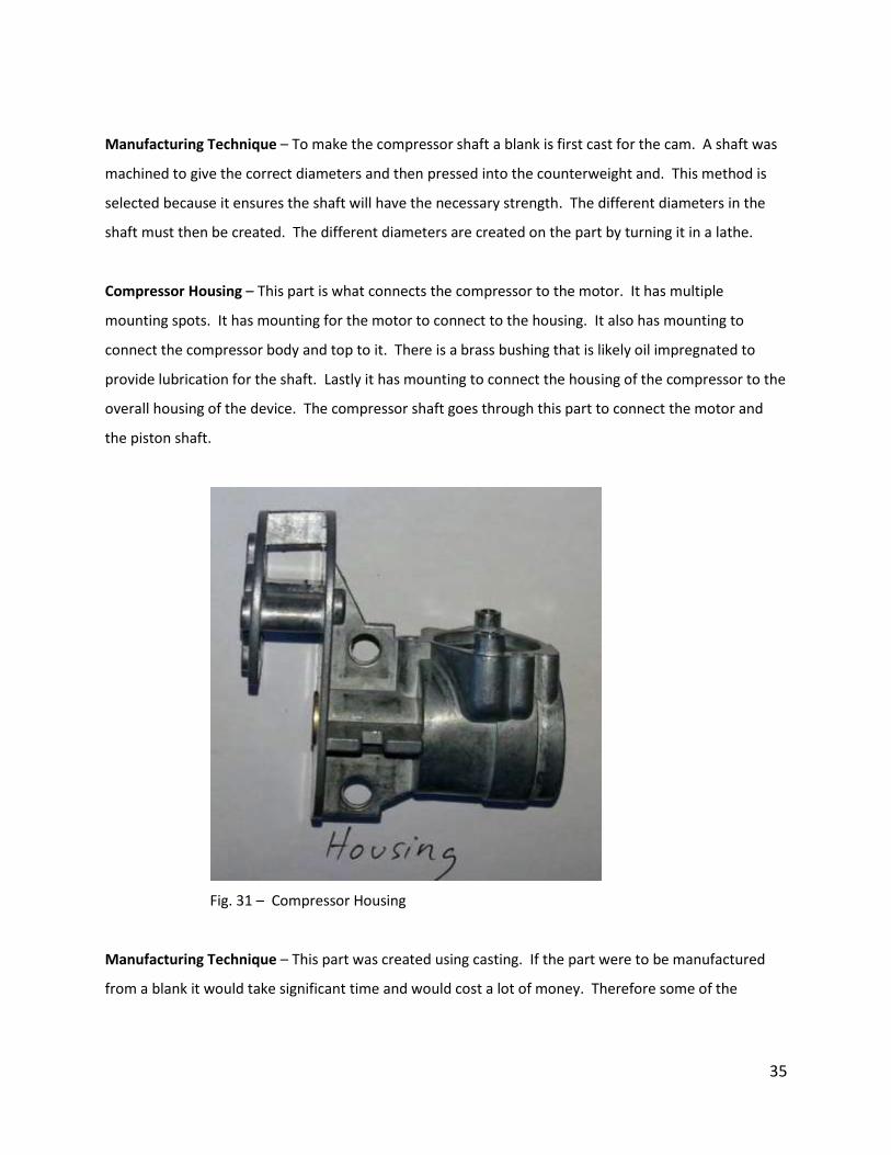
Compressor Shaft – The compressor shaft is what the motor spun in order to move the piston. It has a
cam to give the shaft rotational momentum when spinning. The piston shaft connects to a pin at the
end of the cam. It allows the piston shaft to convert the radial motion into linear motion in the
compressor body.
Fig. 30 – Compressor Shaft
35
Manufacturing Technique – To make the compressor shaft a blank is first cast for the cam. A shaft was
machined to give the correct diameters and then pressed into the counterweight and. This method is
selected because it ensures the shaft will have the necessary strength. The different diameters in the
shaft must then be created. The different diameters are created on the part by turning it in a lathe.
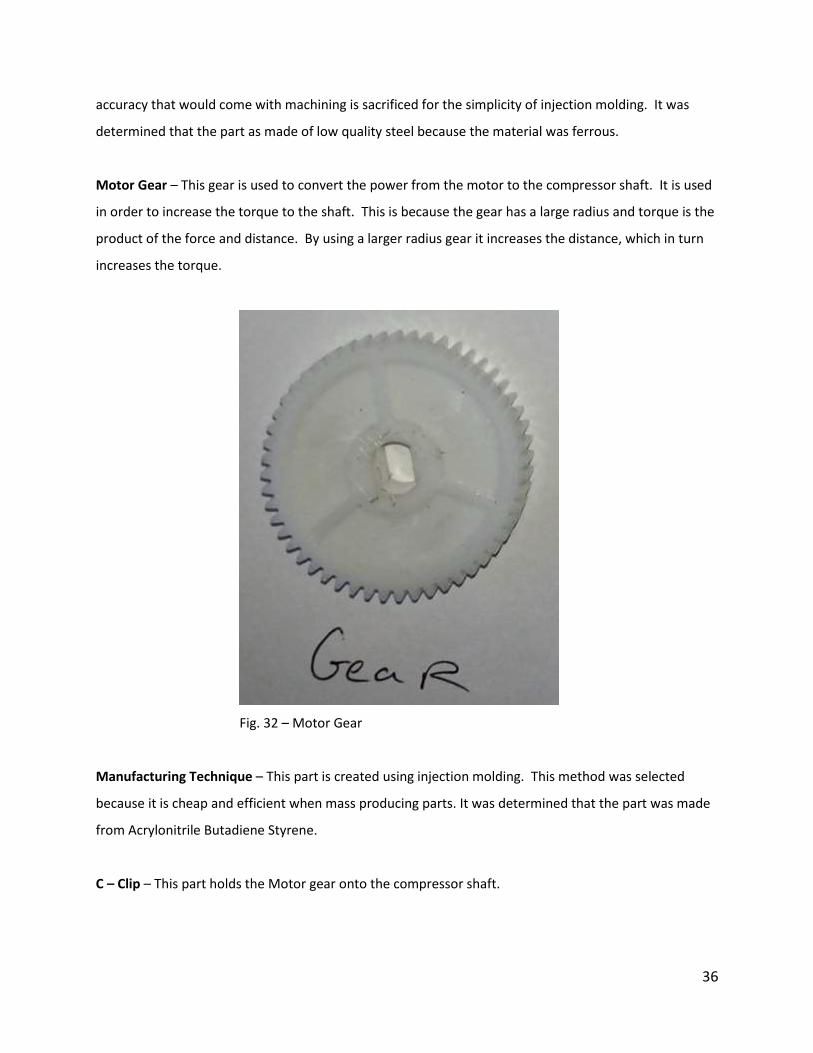
Compressor Housing – This part is what connects the compressor to the motor. It has multiple
mounting spots. It has mounting for the motor to connect to the housing. It also has mounting to
connect the compressor body and top to it. There is a brass bushing that is likely oil impregnated to
provide lubrication for the shaft. Lastly it has mounting to connect the housing of the compressor to the
overall housing of the device. The compressor shaft goes through this part to connect the motor and
the piston shaft.
Fig. 31 – Compressor Housing
Manufacturing Technique – This part was created using casting. If the part were to be manufactured
from a blank it would take significant time and would cost a lot of money. Therefore some of the
36
accuracy that would come with machining is sacrificed for the simplicity of injection molding. It was
determined that the part as made of low quality steel because the material was ferrous.
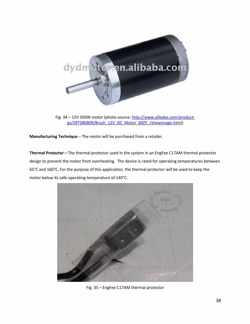
Motor Gear – This gear is used to convert the power from the motor to the compressor shaft. It is used
in order to increase the torque to the shaft. This is because the gear has a large radius and torque is the
product of the force and distance. By using a larger radius gear it increases the distance, which in turn
increases the torque.
Fig. 32 – Motor Gear
Manufacturing Technique – This part is created using injection molding. This method was selected
because it is cheap and efficient when mass producing parts. It was determined that the part was made
from Acrylonitrile Butadiene Styrene.
C – Clip – This part holds the Motor gear onto the compressor shaft.

37
Fig. 33 – C-Clip
Manufacturing Technique – This clip was produced by stamping it out of sheet metal. These metal clips
were made of steel. This was determined by applying a magnet to the part.
Motor – The motor is what supplies the mechanical work for the compressor. The mechanical work
turns the crank shaft which moves the piston. This mechanical work is then used to compress the air
with the piston. The motor operates at 12 V with a maximum output power of 350 W. It provides the
capabilities to fill an 18 L tire from 0-120 psi in just 15 minutes.
38
Fig. 34 – 12V 350W motor (photo source: http://www.alibaba.com/product-gs/297286809/Brush_12V_DC_Motor_60ZY_/showimage.html)
Manufacturing Technique – The motor will be purchased from a retailer.
Thermal Protector – The thermal protector used in the system in an EngFee C17AM thermal protector
design to prevent the motor from overheating. The device is rated for operating temperatures between
65°C and 160°C. For the purpose of this application, the thermal protector will be used to keep the
motor below its safe operating temperature of 140°C.
Fig. 35 – EngFee C17AM thermal protector
39
Manufacturing Technique – The motor will be purchased from a retailer.
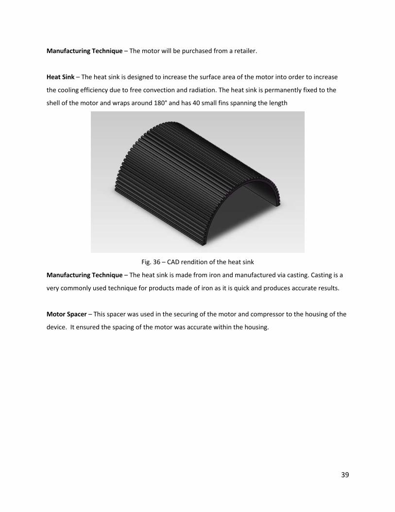
Heat Sink – The heat sink is designed to increase the surface area of the motor into order to increase
the cooling efficiency due to free convection and radiation. The heat sink is permanently fixed to the
shell of the motor and wraps around 180° and has 40 small fins spanning the length
Fig. 36 – CAD rendition of the heat sink
Manufacturing Technique – The heat sink is made from iron and manufactured via casting. Casting is a
very commonly used technique for products made of iron as it is quick and produces accurate results.
Motor Spacer – This spacer was used in the securing of the motor and compressor to the housing of the
device. It ensured the spacing of the motor was accurate within the housing.

40
Fig. 37 – Motor Spacer
Manufacturing Technique – This part was created using injection molding. This method was selected
because it can be done quickly and due to the parts irregular shape. The material used for this part was
found by using the plastic identification chart. When a soldering iron was placed on the material it
melted. The sample sank in water. When the sample was burned it produced a blue flame and smelled
like acrin. When burning it was observed that the sample melted. These results show that the part is
made of Acrylonitrile Butadiene Styrene.
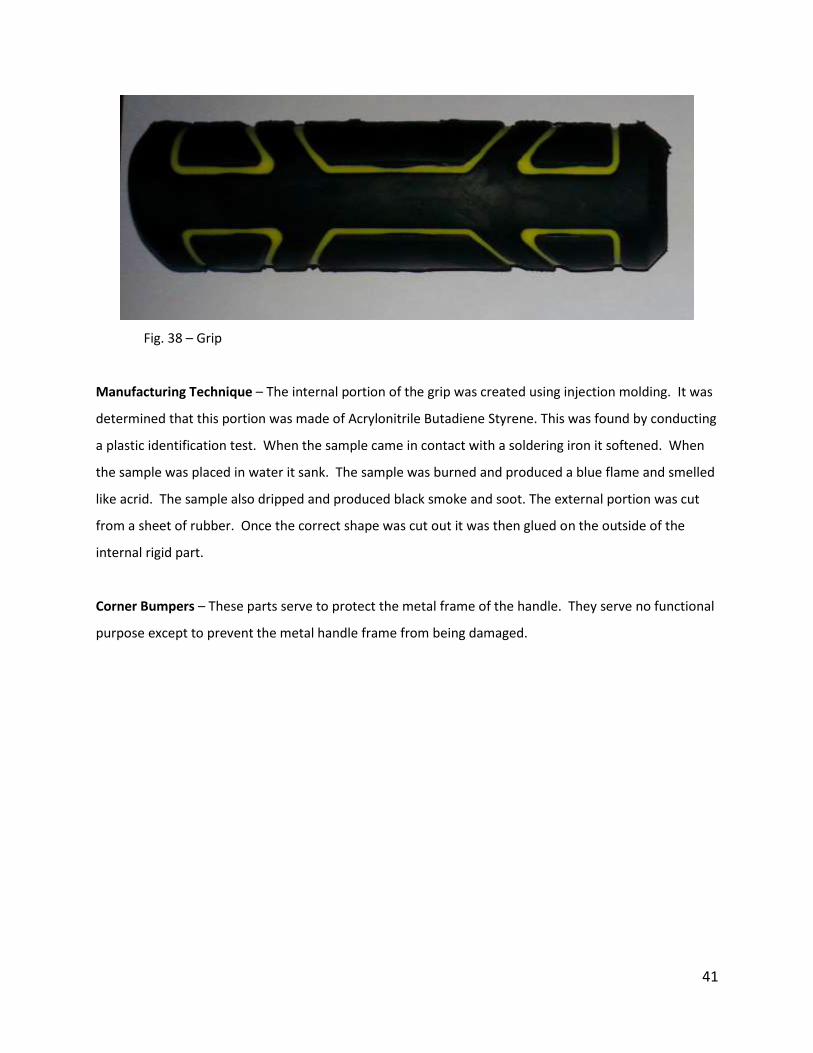
Grip – This part has two different layers. The first layer is the internal portion. It is rigid and provides
structural integrity for the part. The second part is the external grip portion. It is pliable and provides
grip for the handle. The combination of the two materials allows for the grip to both be sturdy while
also providing a good gripping surface.
41
Fig. 38 – Grip
Manufacturing Technique – The internal portion of the grip was created using injection molding. It was
determined that this portion was made of Acrylonitrile Butadiene Styrene. This was found by conducting
a plastic identification test. When the sample came in contact with a soldering iron it softened. When
the sample was placed in water it sank. The sample was burned and produced a blue flame and smelled
like acrid. The sample also dripped and produced black smoke and soot. The external portion was cut
from a sheet of rubber. Once the correct shape was cut out it was then glued on the outside of the
internal rigid part.
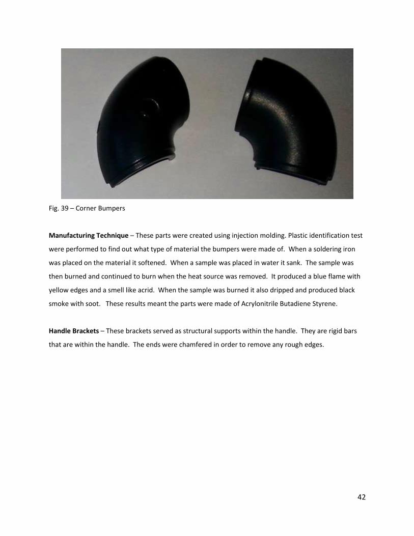
Corner Bumpers – These parts serve to protect the metal frame of the handle. They serve no functional
purpose except to prevent the metal handle frame from being damaged.
42
Fig. 39 – Corner Bumpers
Manufacturing Technique – These parts were created using injection molding. Plastic identification test
were performed to find out what type of material the bumpers were made of. When a soldering iron
was placed on the material it softened. When a sample was placed in water it sank. The sample was
then burned and continued to burn when the heat source was removed. It produced a blue flame with
yellow edges and a smell like acrid. When the sample was burned it also dripped and produced black
smoke with soot. These results meant the parts were made of Acrylonitrile Butadiene Styrene.
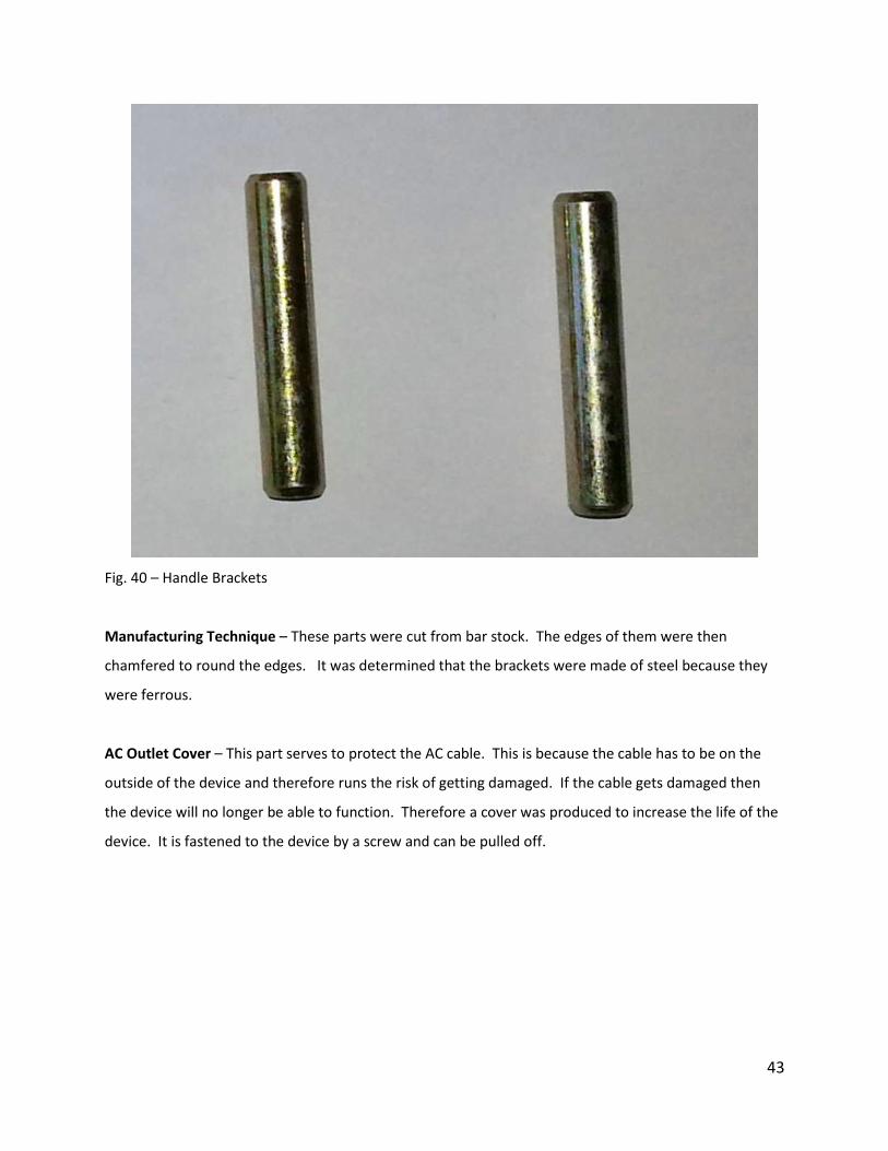
Handle Brackets – These brackets served as structural supports within the handle. They are rigid bars
that are within the handle. The ends were chamfered in order to remove any rough edges.
43
Fig. 40 – Handle Brackets
Manufacturing Technique – These parts were cut from bar stock. The edges of them were then
chamfered to round the edges. It was determined that the brackets were made of steel because they
were ferrous.
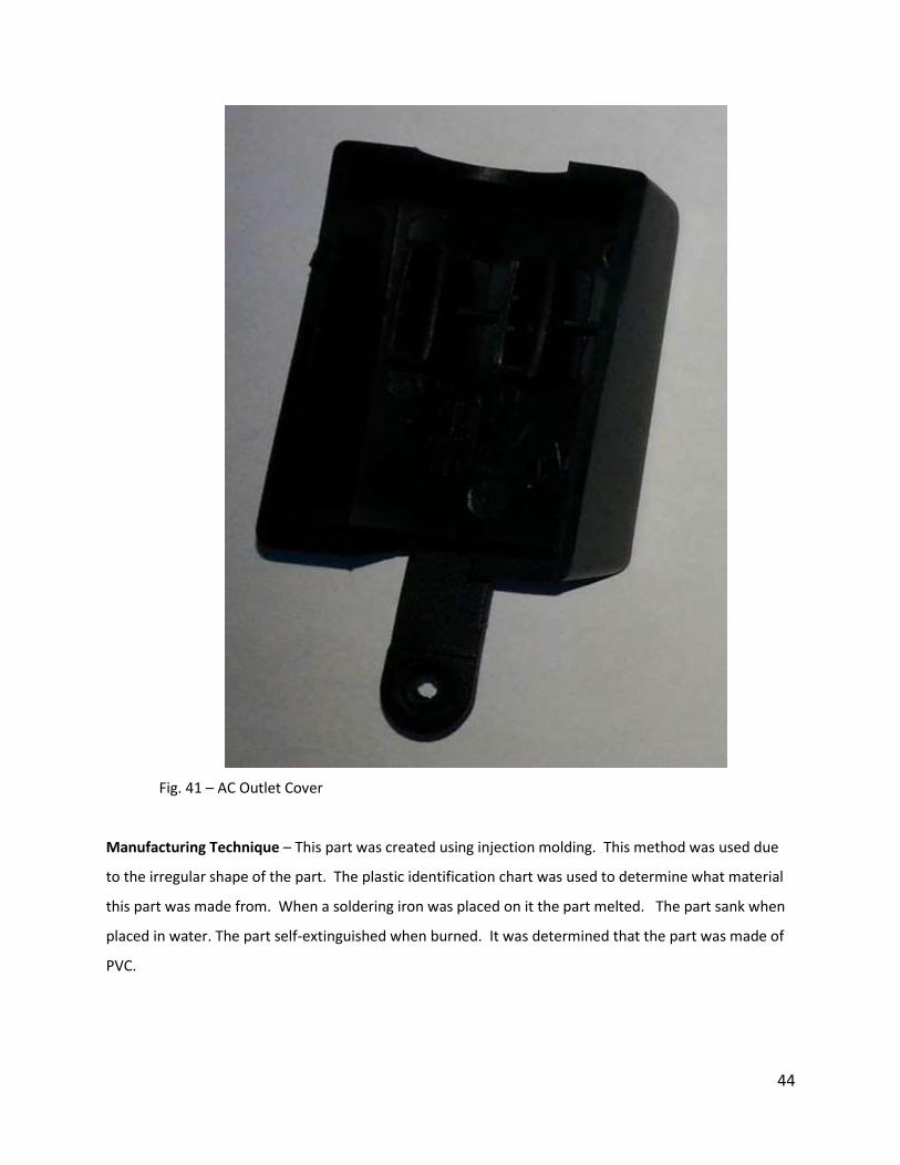
AC Outlet Cover – This part serves to protect the AC cable. This is because the cable has to be on the
outside of the device and therefore runs the risk of getting damaged. If the cable gets damaged then
the device will no longer be able to function. Therefore a cover was produced to increase the life of the
device. It is fastened to the device by a screw and can be pulled off.
44
Fig. 41 – AC Outlet Cover
Manufacturing Technique – This part was created using injection molding. This method was used due
to the irregular shape of the part. The plastic identification chart was used to determine what material
this part was made from. When a soldering iron was placed on it the part melted. The part sank when
placed in water. The part self-extinguished when burned. It was determined that the part was made of
PVC.

45
Compressor On/Off Switch – This is the switch that turns the compressor on and off. It is a simple
toggle switch that completes the circuit for the power to the compressor when toggled on. It is
mounted so it can be used on the outside of the device.
Fig. 42 – Compressor On/OFF Switch
Manufacturing Technique – This part is purchased from a manufacturer. No manufacturing is necessary
for the part.
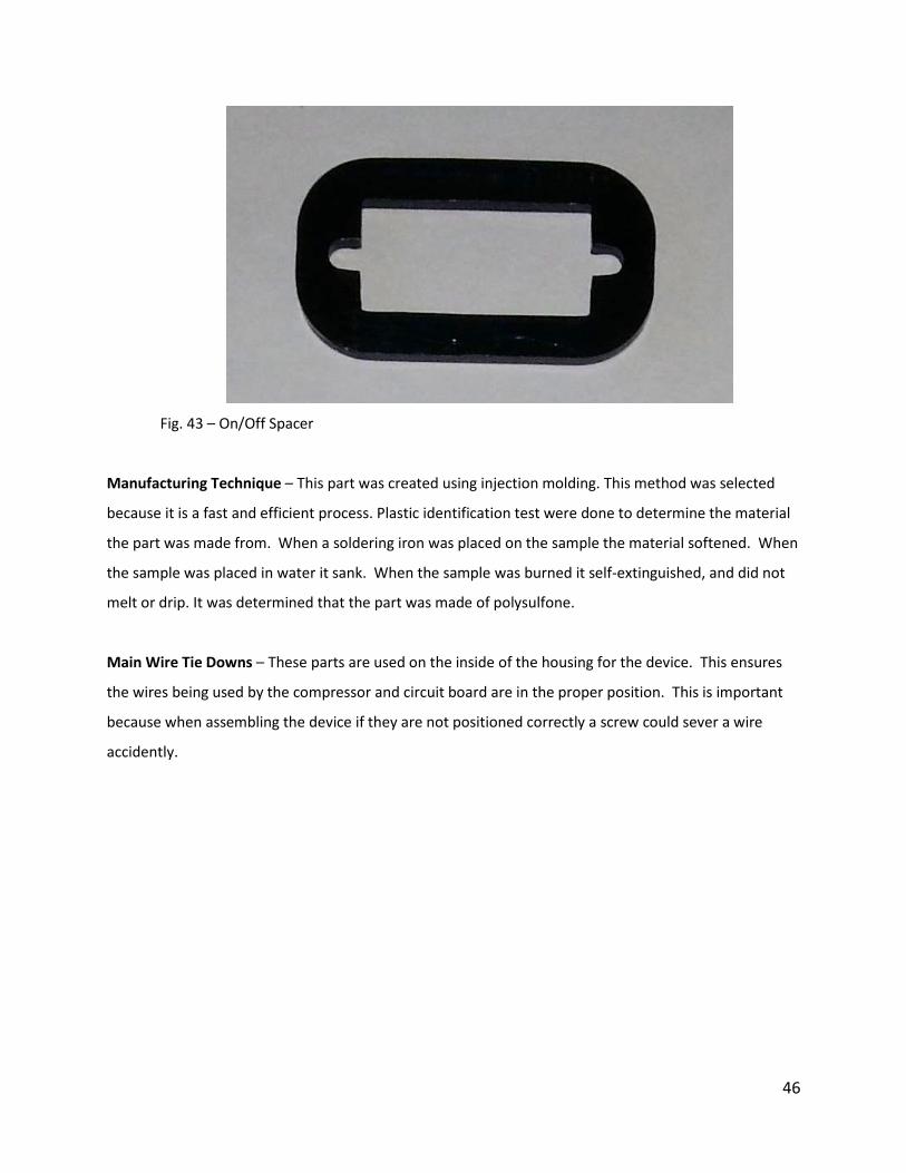
On/Off Spacer – This part is used to position the On/Off switch within the housing. It ensures the
spacing of the switch is correct so it fits in the housing properly.
46
Fig. 43 – On/Off Spacer
Manufacturing Technique – This part was created using injection molding. This method was selected
because it is a fast and efficient process. Plastic identification test were done to determine the material
the part was made from. When a soldering iron was placed on the sample the material softened. When
the sample was placed in water it sank. When the sample was burned it self-extinguished, and did not
melt or drip. It was determined that the part was made of polysulfone.
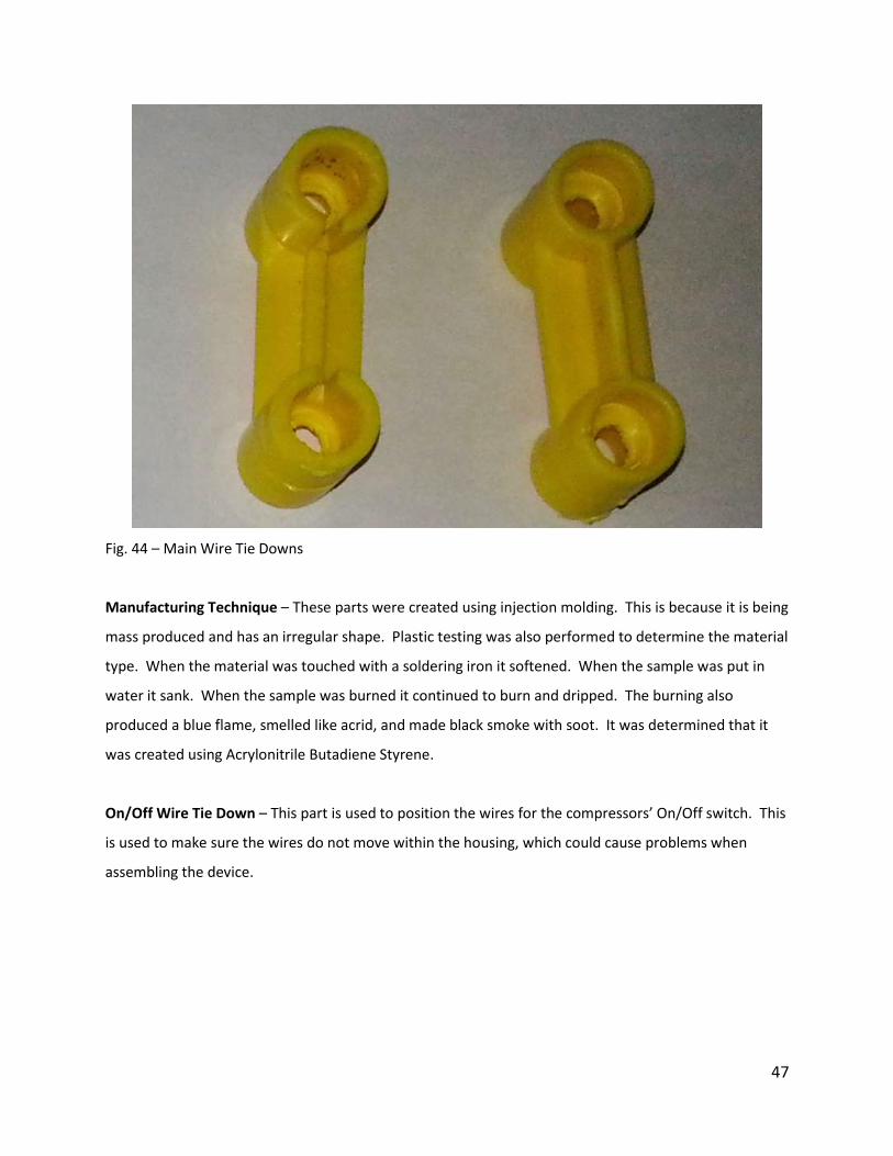
Main Wire Tie Downs – These parts are used on the inside of the housing for the device. This ensures
the wires being used by the compressor and circuit board are in the proper position. This is important
because when assembling the device if they are not positioned correctly a screw could sever a wire
accidently.
47
Fig. 44 – Main Wire Tie Downs
Manufacturing Technique – These parts were created using injection molding. This is because it is being
mass produced and has an irregular shape. Plastic testing was also performed to determine the material
type. When the material was touched with a soldering iron it softened. When the sample was put in
water it sank. When the sample was burned it continued to burn and dripped. The burning also
produced a blue flame, smelled like acrid, and made black smoke with soot. It was determined that it
was created using Acrylonitrile Butadiene Styrene.
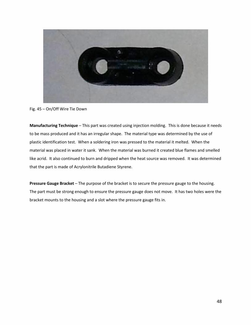
On/Off Wire Tie Down – This part is used to position the wires for the compressors’ On/Off switch. This
is used to make sure the wires do not move within the housing, which could cause problems when
assembling the device.
48
Fig. 45 – On/Off Wire Tie Down
Manufacturing Technique – This part was created using injection molding. This is done because it needs
to be mass produced and it has an irregular shape. The material type was determined by the use of
plastic identification test. When a soldering iron was pressed to the material it melted. When the
material was placed in water it sank. When the material was burned it created blue flames and smelled
like acrid. It also continued to burn and dripped when the heat source was removed. It was determined
that the part is made of Acrylonitrile Butadiene Styrene.
Pressure Gauge Bracket – The purpose of the bracket is to secure the pressure gauge to the housing.
The part must be strong enough to ensure the pressure gauge does not move. It has two holes were the
bracket mounts to the housing and a slot where the pressure gauge fits in.

49
Fig. 46 – Pressure Gauge Bracket
Manufacturing Technique – This part was created by first stamping a blank from sheet metal. It is then
mechanically deformed. One end of the blank is bent to the desired angle. Lastly the two holes are
drilled so it can be mounted to the housing. It was determined that the bracket was made of steel. This
is because the material is ferrous.
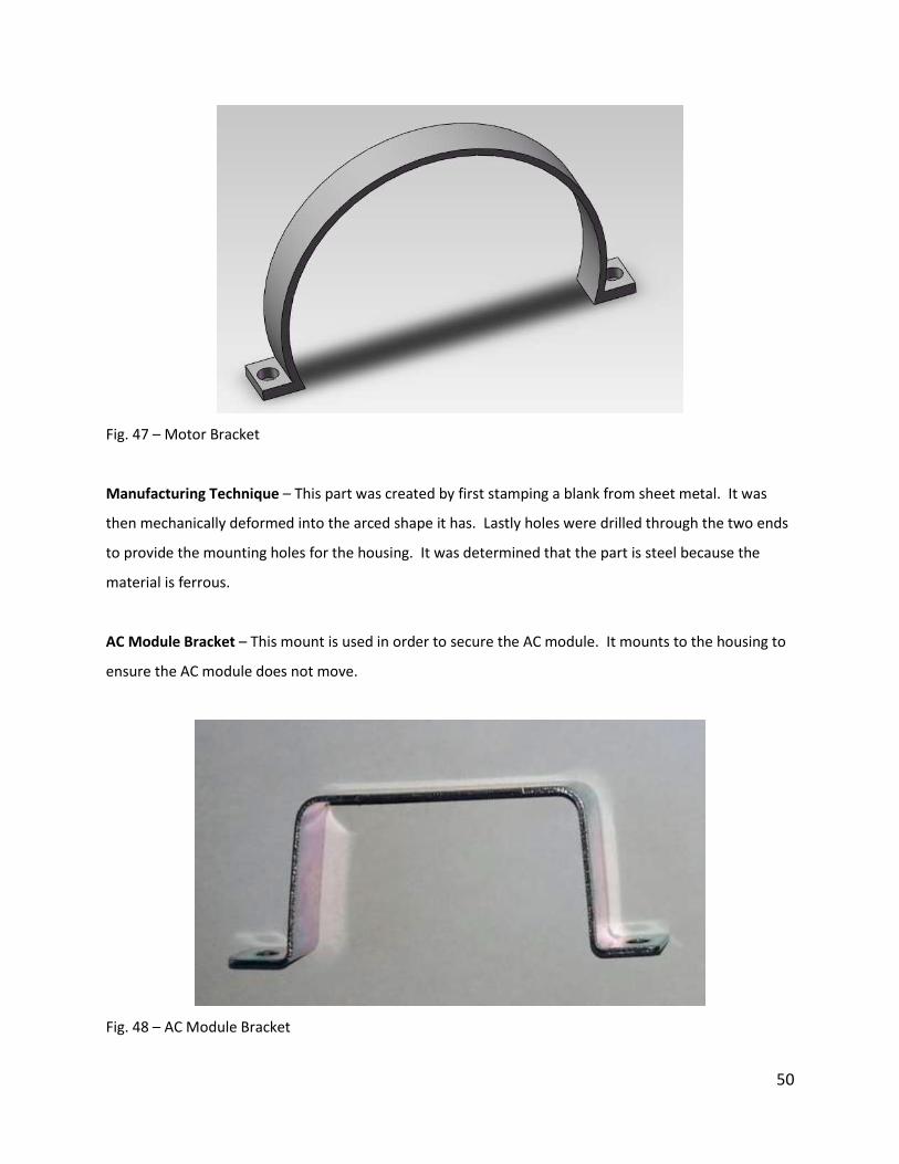
Motor Bracket – This bracket is used in order to secure the motor to the housing. It has one space in
the bracket to make room for the wires that run to the motor.
50
Fig. 47 – Motor Bracket
Manufacturing Technique – This part was created by first stamping a blank from sheet metal. It was
then mechanically deformed into the arced shape it has. Lastly holes were drilled through the two ends
to provide the mounting holes for the housing. It was determined that the part is steel because the
material is ferrous.
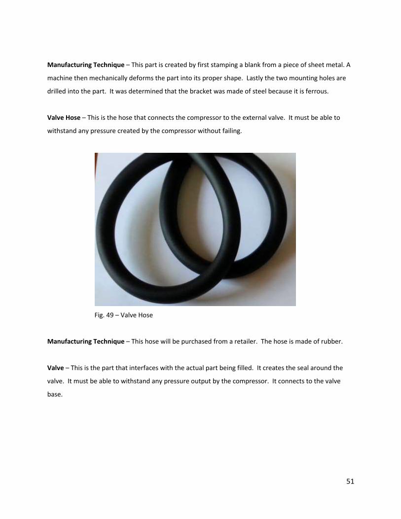
AC Module Bracket – This mount is used in order to secure the AC module. It mounts to the housing to
ensure the AC module does not move.
Fig. 48 – AC Module Bracket
51
Manufacturing Technique – This part is created by first stamping a blank from a piece of sheet metal. A
machine then mechanically deforms the part into its proper shape. Lastly the two mounting holes are
drilled into the part. It was determined that the bracket was made of steel because it is ferrous.
Valve Hose – This is the hose that connects the compressor to the external valve. It must be able to
withstand any pressure created by the compressor without failing.
Fig. 49 – Valve Hose
Manufacturing Technique – This hose will be purchased from a retailer. The hose is made of rubber.
Valve – This is the part that interfaces with the actual part being filled. It creates the seal around the
valve. It must be able to withstand any pressure output by the compressor. It connects to the valve
base.

52
Fig. 50 – Valve
Manufacturing Technique – This part is created by the technique of injection molding. This process was
used because it allows for the part to be quickly produced. This is important when mass producing a
product. The material the valve was made with was determined using plastic identification tests. When
a soldering iron was placed on the material it softened. When the sample was placed in water it sank.
When the sample was burned it continued to burn and dripped. It was determined that the part was
made of Acrylonitrile Butadiene Styrene.
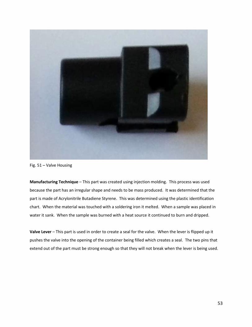
Valve Housing – This is the external part that goes around the valve. It serves to protect the housing
and also lines up the valve with the container opening it is filling. It also works with the valve lever to
create the seal for the valve.
53
Fig. 51 – Valve Housing
Manufacturing Technique – This part was created using injection molding. This process was used
because the part has an irregular shape and needs to be mass produced. It was determined that the
part is made of Acrylonitrile Butadiene Styrene. This was determined using the plastic identification
chart. When the material was touched with a soldering iron it melted. When a sample was placed in
water it sank. When the sample was burned with a heat source it continued to burn and dripped.
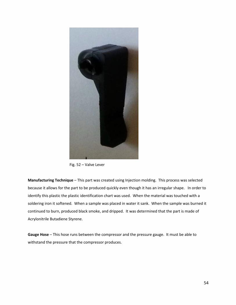
Valve Lever – This part is used in order to create a seal for the valve. When the lever is flipped up it
pushes the valve into the opening of the container being filled which creates a seal. The two pins that
extend out of the part must be strong enough so that they will not break when the lever is being used.
54
Fig. 52 – Valve Lever
Manufacturing Technique – This part was created using Injection molding. This process was selected
because it allows for the part to be produced quickly even though it has an irregular shape. In order to
identify this plastic the plastic identification chart was used. When the material was touched with a
soldering iron it softened. When a sample was placed in water it sank. When the sample was burned it
continued to burn, produced black smoke, and dripped. It was determined that the part is made of
Acrylonitrile Butadiene Styrene.
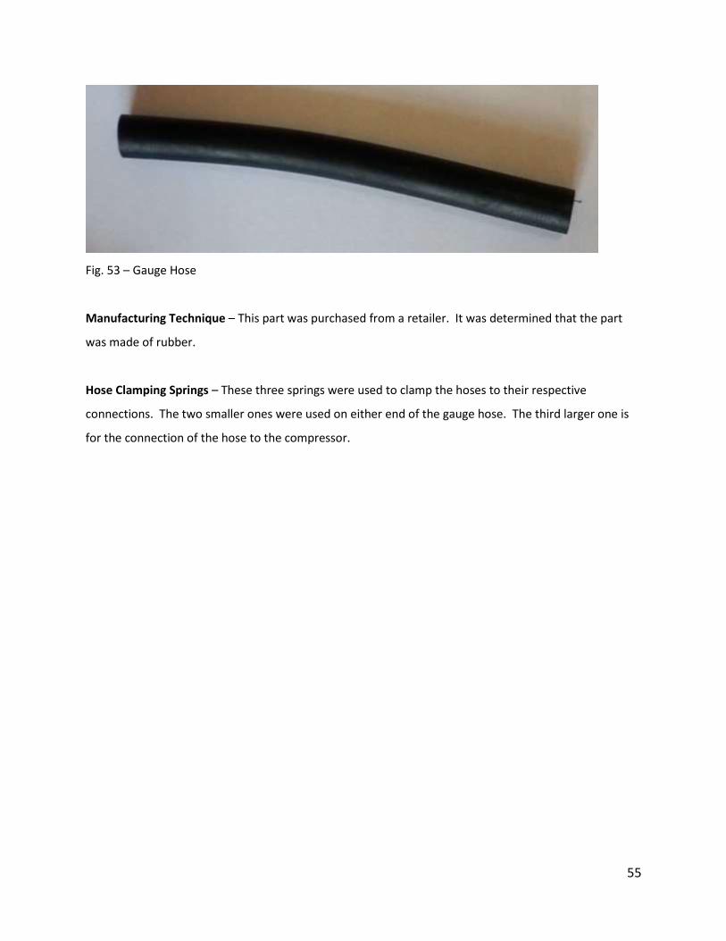
Gauge Hose – This hose runs between the compressor and the pressure gauge. It must be able to
withstand the pressure that the compressor produces.
55
Fig. 53 – Gauge Hose
Manufacturing Technique – This part was purchased from a retailer. It was determined that the part
was made of rubber.
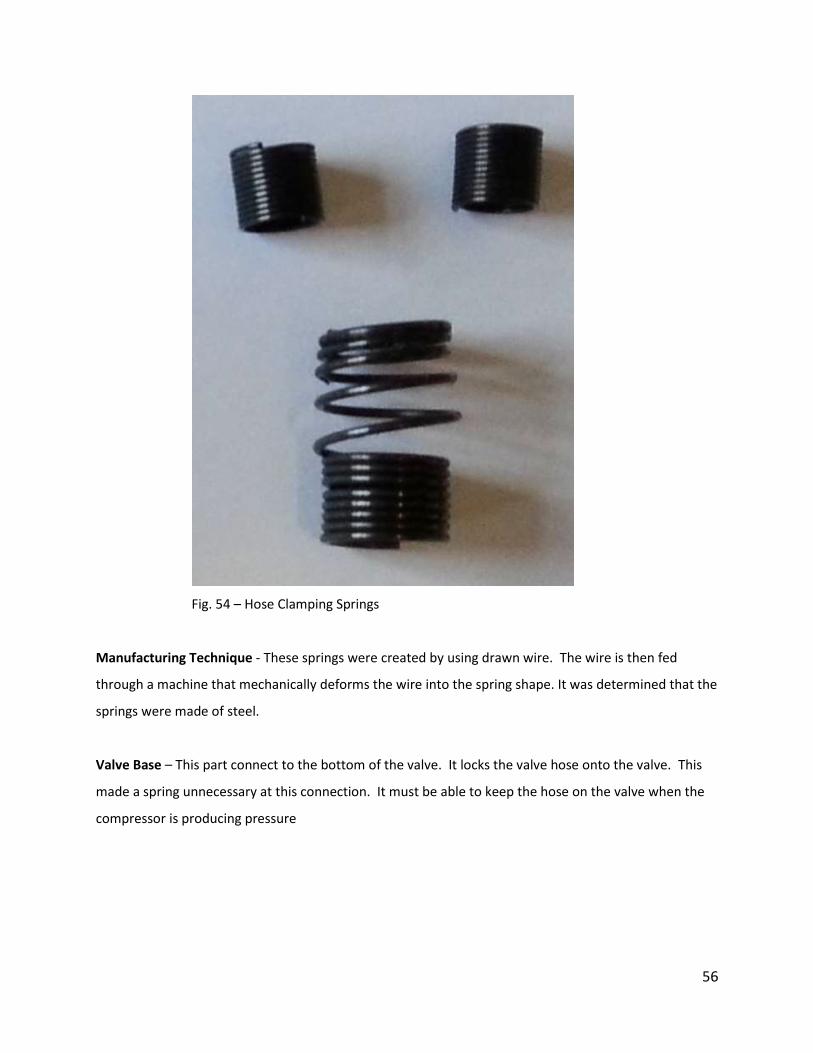
Hose Clamping Springs – These three springs were used to clamp the hoses to their respective
connections. The two smaller ones were used on either end of the gauge hose. The third larger one is
for the connection of the hose to the compressor.
56
Fig. 54 – Hose Clamping Springs
Manufacturing Technique - These springs were created by using drawn wire. The wire is then fed
through a machine that mechanically deforms the wire into the spring shape. It was determined that the
springs were made of steel.
Valve Base – This part connect to the bottom of the valve. It locks the valve hose onto the valve. This
made a spring unnecessary at this connection. It must be able to keep the hose on the valve when the
compressor is producing pressure

57
Fig. 55 – Valve Base
Manufacturing Technique – This part was purchased from a retailer
Clamp Handle – This part is used in order to form the clamp, which connects to the battery. The handle
must be strong enough to withstand the force generated by the spring, which causes the clamp to close.
It has three holes. Two are for the clamp to pivot around and the third is for a screw that secures the
lead wire.
Fig. 56 – Clamp Handle
58
Manufacturing Technique – A blank is first stamped out of a piece of sheet metal. The groves on the
back of the clam are then stamped into the part and the two holes that the grips pivot around are
drilled. Lastly the sides of the clamps are then folded up to form the clamp and it is painted. The clamp
is made of steel.
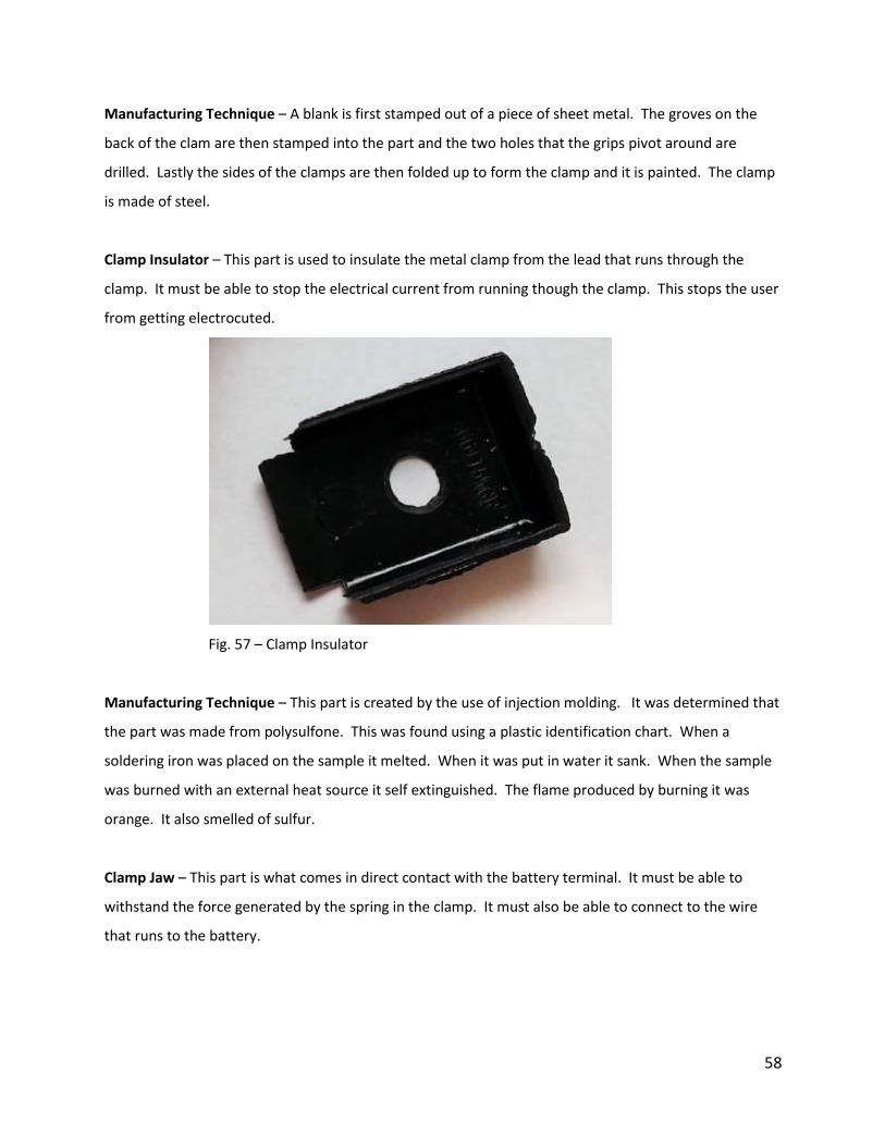
Clamp Insulator – This part is used to insulate the metal clamp from the lead that runs through the
clamp. It must be able to stop the electrical current from running though the clamp. This stops the user
from getting electrocuted.
Fig. 57 – Clamp Insulator
Manufacturing Technique – This part is created by the use of injection molding. It was determined that
the part was made from polysulfone. This was found using a plastic identification chart. When a
soldering iron was placed on the sample it melted. When it was put in water it sank. When the sample
was burned with an external heat source it self extinguished. The flame produced by burning it was
orange. It also smelled of sulfur.
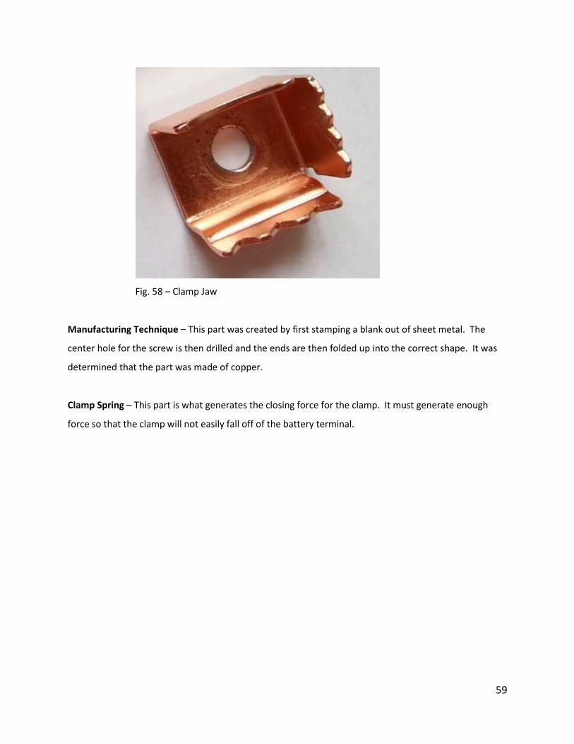
Clamp Jaw – This part is what comes in direct contact with the battery terminal. It must be able to
withstand the force generated by the spring in the clamp. It must also be able to connect to the wire
that runs to the battery.
59
Fig. 58 – Clamp Jaw
Manufacturing Technique – This part was created by first stamping a blank out of sheet metal. The
center hole for the screw is then drilled and the ends are then folded up into the correct shape. It was
determined that the part was made of copper.
Clamp Spring – This part is what generates the closing force for the clamp. It must generate enough
force so that the clamp will not easily fall off of the battery terminal.
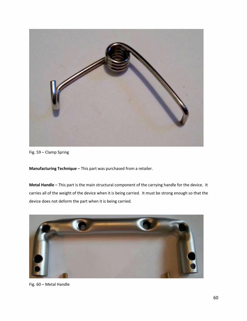
60
Fig. 59 – Clamp Spring
Manufacturing Technique – This part was purchased from a retailer.
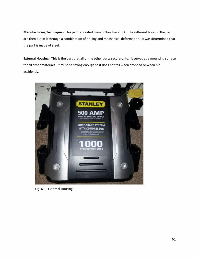
Metal Handle – This part is the main structural component of the carrying handle for the device. It
carries all of the weight of the device when it is being carried. It must be strong enough so that the
device does not deform the part when it is being carried.
Fig. 60 – Metal Handle
61
Manufacturing Technique – This part is created from hollow bar stock. The different holes in the part
are then put in it through a combination of drilling and mechanical deformation. It was determined that
the part is made of steel.
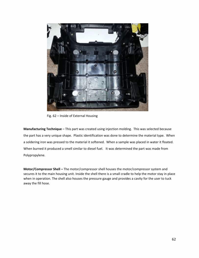
External Housing - This is the part that all of the other parts secure onto. It serves as a mounting surface
for all other materials. It must be strong enough so it does not fail when dropped or when hit
accidently.
Fig. 61 – External Housing
62
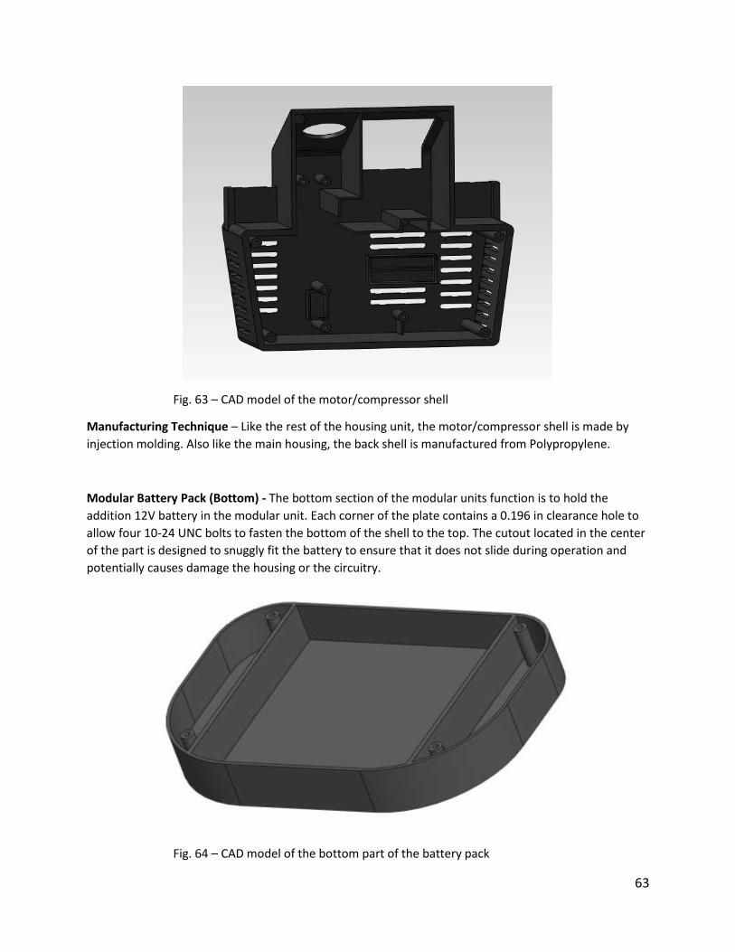
Fig. 62 – Inside of External Housing
Manufacturing Technique – This part was created using injection molding. This was selected because
the part has a very unique shape. Plastic identification was done to determine the material type. When
a soldering iron was pressed to the material it softened. When a sample was placed in water it floated.
When burned it produced a smell similar to diesel fuel. It was determined the part was made from
Polypropylene.
Motor/Compressor Shell – The motor/compressor shell houses the motor/compressor system and
secures it to the main housing unit. Inside the shell there is a small cradle to help the motor stay in place
when in operation. The shell also houses the pressure gauge and provides a cavity for the user to tuck
away the fill hose.
63
Fig. 63 – CAD model of the motor/compressor shell
Manufacturing Technique – Like the rest of the housing unit, the motor/compressor shell is made by
injection molding. Also like the main housing, the back shell is manufactured from Polypropylene.
Modular Battery Pack (Bottom) - The bottom section of the modular units function is to hold the
addition 12V battery in the modular unit. Each corner of the plate contains a 0.196 in clearance hole to
allow four 10-24 UNC bolts to fasten the bottom of the shell to the top. The cutout located in the center
of the part is designed to snuggly fit the battery to ensure that it does not slide during operation and
potentially causes damage the housing or the circuitry.
Fig. 64 – CAD model of the bottom part of the battery pack

64
Manufacturing Technique – The part is to be made via injection molding for rapid production at
relatively low costs, as well as tight tolerances to ensure that any bottom taken from the production line
will fit properly to any top.
Modular Battery Pack (Top) - The top section of the modular unit completes the housing that encases
the new additional battery. The part was designed such that it seats comfortably over the battery and
leaves room for the small 12V to 24V circuit and the needed wires. Located at each corner on the inner
surface is a screw post tapped for a 10-24 UNC fastener in order to secure the top and bottom sections
together. Protruding from the top of the part is an AC like plug wired to the battery that allows for the
connection between the modular battery and the standard internal battery. Also located on the top of
the part are two solid posts with notches cut out from the top that snap into the unit’s bottom plate.
Fig. 65 –CAD model of the top part of the battery pack
Manufacturing Technique – For the same reasons as the bottom section, this part is to be made via
injection molding. After molding, the four screw posts would need to be manually or mechanically
tapped for a 10-24 UNC screw. The metal contacts, for the electrical outlet will be molded directly into
the unit.
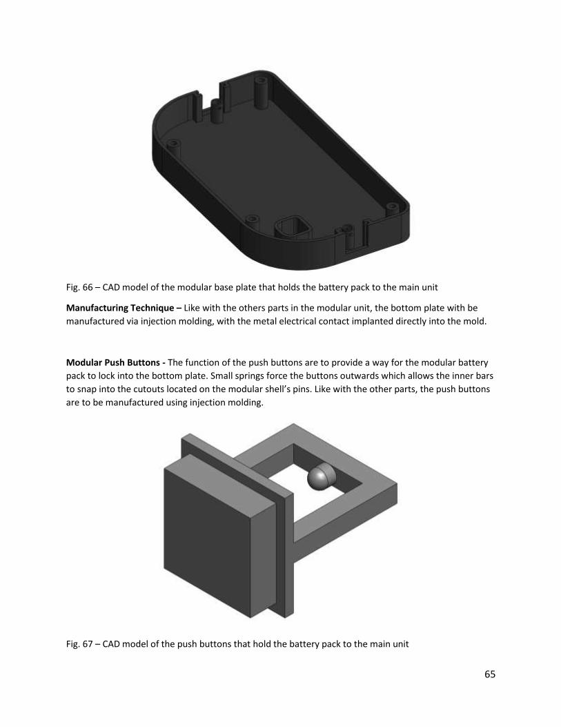
Modular Bottom Plate -The purpose of the bottom plate is to allow the modular batter pack to fit
together with the main unit. The bottom plate secures to the main unit using four 10-24 UNC screws.
Again, this part is made through an injection molding process. There are two posts on each side of the
part in which the posts from the battery pack top piece fit. This part also houses two spring dependent
push button that lock and release the posts from the battery pack. The part also contains a receptacle
for the AC style plug on the battery pack. The receptacle is wired directly to the main unit’s battery and
enables it to be wired together with the modular battery.
65
Fig. 66 – CAD model of the modular base plate that holds the battery pack to the main unit
Manufacturing Technique – Like with the others parts in the modular unit, the bottom plate with be
manufactured via injection molding, with the metal electrical contact implanted directly into the mold.
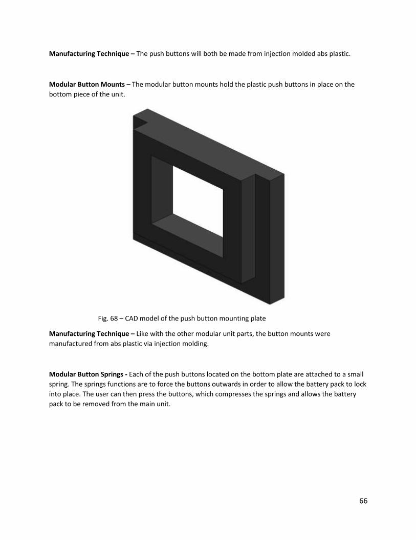
Modular Push Buttons - The function of the push buttons are to provide a way for the modular battery
pack to lock into the bottom plate. Small springs force the buttons outwards which allows the inner bars
to snap into the cutouts located on the modular shell’s pins. Like with the other parts, the push buttons
are to be manufactured using injection molding.
Fig. 67 – CAD model of the push buttons that hold the battery pack to the main unit
66
Manufacturing Technique – The push buttons will both be made from injection molded abs plastic.
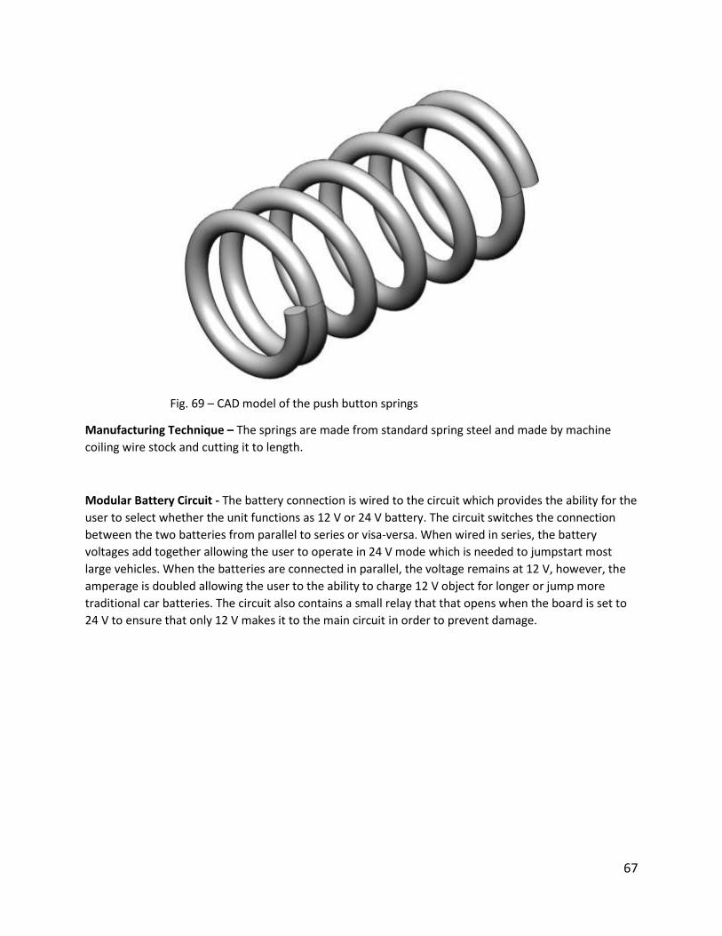
Modular Button Mounts – The modular button mounts hold the plastic push buttons in place on the
bottom piece of the unit.
Fig. 68 – CAD model of the push button mounting plate
Manufacturing Technique – Like with the other modular unit parts, the button mounts were
manufactured from abs plastic via injection molding.
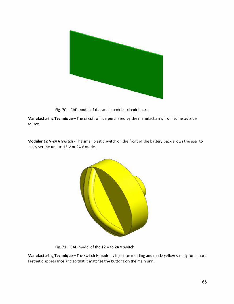
Modular Button Springs - Each of the push buttons located on the bottom plate are attached to a small
spring. The springs functions are to force the buttons outwards in order to allow the battery pack to lock
into place. The user can then press the buttons, which compresses the springs and allows the battery
pack to be removed from the main unit.
67
Fig. 69 – CAD model of the push button springs
Manufacturing Technique – The springs are made from standard spring steel and made by machine
coiling wire stock and cutting it to length.
Modular Battery Circuit - The battery connection is wired to the circuit which provides the ability for the
user to select whether the unit functions as 12 V or 24 V battery. The circuit switches the connection
between the two batteries from parallel to series or visa-versa. When wired in series, the battery
voltages add together allowing the user to operate in 24 V mode which is needed to jumpstart most
large vehicles. When the batteries are connected in parallel, the voltage remains at 12 V, however, the
amperage is doubled allowing the user to the ability to charge 12 V object for longer or jump more
traditional car batteries. The circuit also contains a small relay that that opens when the board is set to
24 V to ensure that only 12 V makes it to the main circuit in order to prevent damage.
68
Fig. 70 – CAD model of the small modular circuit board
Manufacturing Technique – The circuit will be purchased by the manufacturing from some outside
source.
Modular 12 V-24 V Switch - The small plastic switch on the front of the battery pack allows the user to
easily set the unit to 12 V or 24 V mode.
Fig. 71 – CAD model of the 12 V to 24 V switch
Manufacturing Technique – The switch is made by injection molding and made yellow strictly for a more
aesthetic appearance and so that it matches the buttons on the main unit.
69
Modular Unit Material Selection - The part will be manufactured from acrylonitrile butadiene styrene or
ABS. ABS is the material of choice for a variety of different reasons. First and foremost, ABS is a very
strong and rigid material and will have no problems handling the weight of the battery without flexing or
cracking. ABS is also a cheap material and is extremely easy to mold. According the label located on the
battery, its safe operating temperature, likely above the max temperature it would ever achieve when in
use, is 150°F. ABS is able to maintain constant material properties for temperatures up to 180°F.
Another useful property of ABS is the fact that it is resistant to a wide variety of acids and bases.
Because this product will be used around automobiles, it is safe to assume that it will likely encounter
various fluids and must be able to maintain structural integrity. ABS also has very good electrical
resistivity. The modular shell contains a small circuit and a very high powered battery. The resistivity of
ABS not only protects the internal components from outside sources, but it may also help protect the
user in the event of a short. Finally, the material is very impact resistant. The tool is likely to be placed
on hard surfaces multiple times throughout its life. Due to the products heavy weight, the unit will
experience moderate impact forces when set down, thus the bottom material must be able to withstand
this force without fracturing or experiencing crack propagation.
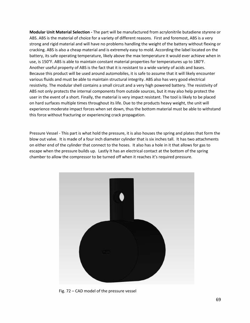
Pressure Vessel - This part is what hold the pressure, it is also houses the spring and plates that form the
blow out valve. It is made of a four inch diameter cylinder that is six inches tall. It has two attachments
on either end of the cylinder that connect to the hoses. It also has a hole in it that allows for gas to
escape when the pressure builds up. Lastly It has an electrical contact at the bottom of the spring
chamber to allow the compressor to be turned off when it reaches it’s required pressure.
Fig. 72 – CAD model of the pressure vessel
70
Manufacturing Technique – This part was made of ABS. This material was selected because it is rigid
and sturdy. It will be able to stand up to the wear and tear the device receives. The part was created
using injection molding.
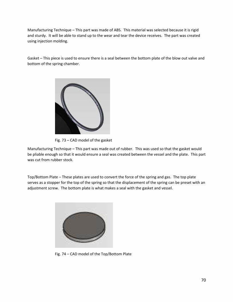
Gasket – This piece is used to ensure there is a seal between the bottom plate of the blow out valve and
bottom of the spring chamber.
Fig. 73 – CAD model of the gasket
Manufacturing Technique – This part was made out of rubber. This was used so that the gasket would
be pliable enough so that it would ensure a seal was created between the vessel and the plate. This part
was cut from rubber stock.
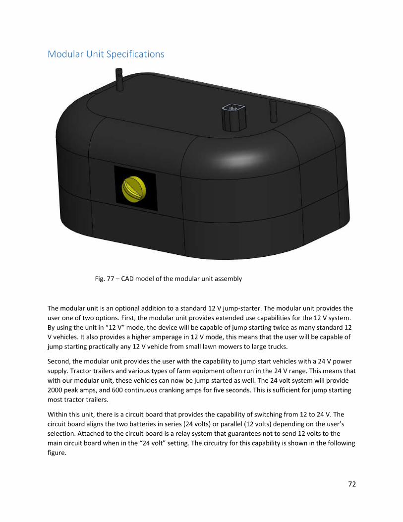
Top/Bottom Plate – These plates are used to convert the force of the spring and gas. The top plate
serves as a stopper for the top of the spring so that the displacement of the spring can be preset with an
adjustment screw. The bottom plate is what makes a seal with the gasket and vessel.
Fig. 74 – CAD model of the Top/Bottom Plate

71
Manufacturing Technique – The plates were created by stamping tenth of an inch sheet metal. It was
decided that the plates would be made of stainless steel so that they would be able to be used in any
condition with out corroding or deteriorating over time.
Spring – A spring is used in order to generate a force on the bottom plate to counteract the force
generated by the gas in the vessel. It was determined that the spring would have a spring constant of
47.1 lbs per inch. The resting length of the spring is 2.5 inches.
Fig. 75 – CAD model of the spring
Manufacturing Technique – This spring was created by mechanical deformation of a rod of steel.
Adjustment fastener – This fastener allows for the blow out pressure of the vessel to be adjusted. It was
determined that it would need three threads per inch. Each quarter turn of the fastener equates to a
blow out pressure increase of five psi.
Fig. 76 – CAD model of the adjustment fastener
Manufacturing Technique – This part will be created by first casting blanks and then rolling the proper
threads onto the shaft.
72
Modular Unit Specifications
Fig. 77 – CAD model of the modular unit assembly
The modular unit is an optional addition to a standard 12 V jump-starter. The modular unit provides the
user one of two options. First, the modular unit provides extended use capabilities for the 12 V system.
By using the unit in “12 V” mode, the device will be capable of jump starting twice as many standard 12
V vehicles. It also provides a higher amperage in 12 V mode, this means that the user will be capable of
jump starting practically any 12 V vehicle from small lawn mowers to large trucks.
Second, the modular unit provides the user with the capability to jump start vehicles with a 24 V power
supply. Tractor trailers and various types of farm equipment often run in the 24 V range. This means that
with our modular unit, these vehicles can now be jump started as well. The 24 volt system will provide
2000 peak amps, and 600 continuous cranking amps for five seconds. This is sufficient for jump starting
most tractor trailers.
Within this unit, there is a circuit board that provides the capability of switching from 12 to 24 V. The
circuit board aligns the two batteries in series (24 volts) or parallel (12 volts) depending on the user’s
selection. Attached to the circuit board is a relay system that guarantees not to send 12 volts to the
main circuit board when in the “24 volt” setting. The circuitry for this capability is shown in the following
figure.

73
Fig. 78 – 12 to 24 V circuit board
When the 24 volt option is selected, the relay is opened, only allowing one battery to power the main
circuit board. This circuitry allows the switching between 12 and 24 volts in a safe and seamless manner.
There is a pressure relay switch that is activated when the modular unit is plugged in to the main unit.
This relay ensures that the male plug on the modular unit is only “live” when it is plugged in to the main
unit. This feature was added to ensure user safety. When the modular unit is detached from the main
unit, the switch is tripped, and the plug becomes dead until reattached for further use.
The modular unit was designed out of abs plastic to encase the additional 12 V lead-acid battery safely
and securely. The case is held together by four 10-24 x 1.5” stainless steel Phillip’s head fasteners. The
abs plastic offered ideal toughness, impact resistance, and insulation. It was also extremely cheap and
readily available in the marketplace.
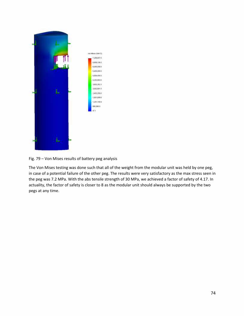
The two connection pegs on top of the modular unit were designed to guarantee solid hold of the
modular unit at all times. A Von Mises analysis was performed to analyze the amount of stress that the
peg would see in use under a worst case scenario. The Von Mises results can be seen in the figure
below.
74
Fig. 79 – Von Mises results of battery peg analysis
The Von Mises testing was done such that all of the weight from the modular unit was held by one peg,
in case of a potential failure of the other peg. The results were very satisfactory as the max stress seen in
the peg was 7.2 MPa. With the abs tensile strength of 30 MPa, we achieved a factor of safety of 4.17. In
actuality, the factor of safety is closer to 8 as the modular unit should always be supported by the two
pegs at any time.
75
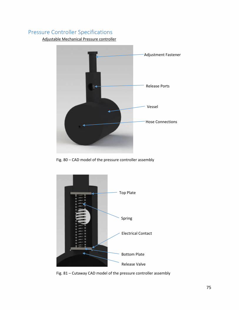
Pressure Controller Specifications Adjustable Mechanical Pressure controller
Fig. 80 – CAD model of the pressure controller assembly
Fig. 81 – Cutaway CAD model of the pressure controller assembly
Release Ports
Adjustment Fastener
Top Plate
Spring
Bottom Plate
Vessel
Hose Connections
Release Valve
Electrical Contact
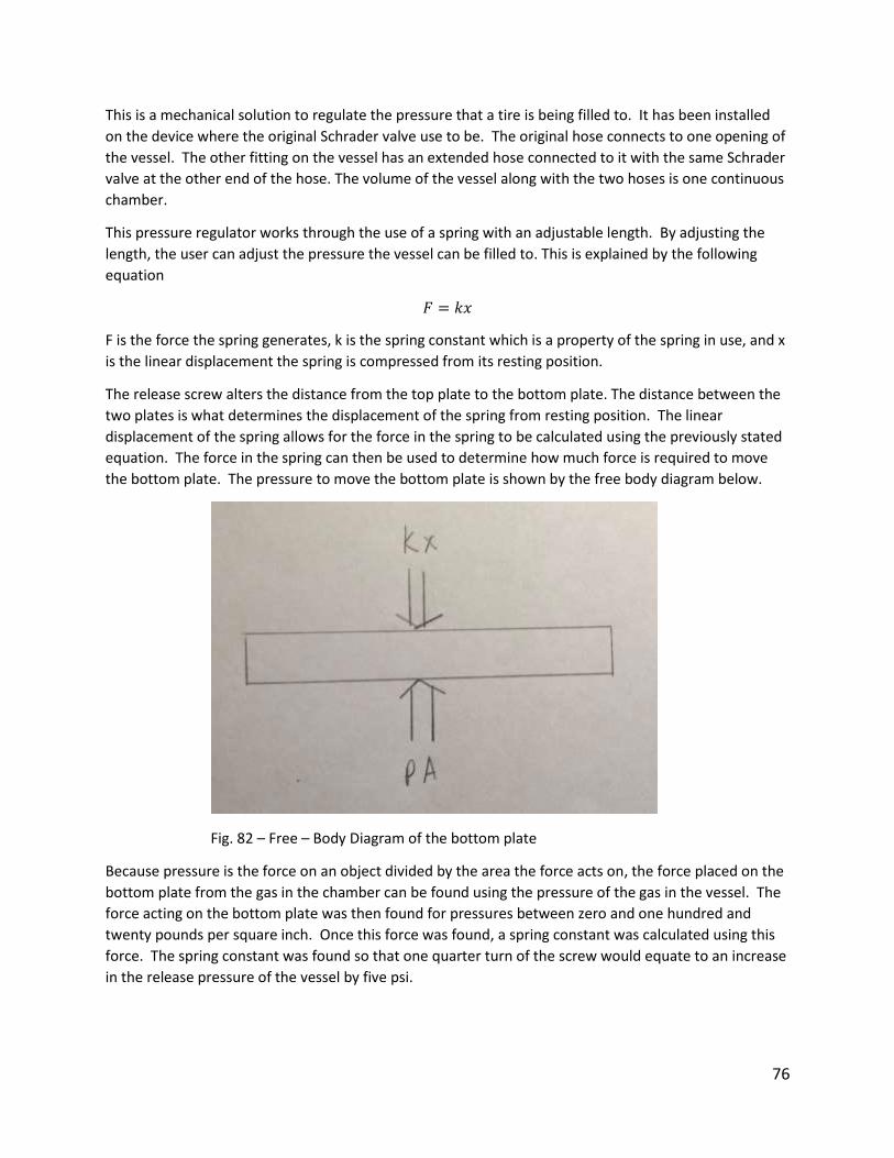
76
This is a mechanical solution to regulate the pressure that a tire is being filled to. It has been installed
on the device where the original Schrader valve use to be. The original hose connects to one opening of
the vessel. The other fitting on the vessel has an extended hose connected to it with the same Schrader
valve at the other end of the hose. The volume of the vessel along with the two hoses is one continuous
chamber.
This pressure regulator works through the use of a spring with an adjustable length. By adjusting the
length, the user can adjust the pressure the vessel can be filled to. This is explained by the following
equation
𝐹 = 𝑘𝑥
F is the force the spring generates, k is the spring constant which is a property of the spring in use, and x
is the linear displacement the spring is compressed from its resting position.
The release screw alters the distance from the top plate to the bottom plate. The distance between the
two plates is what determines the displacement of the spring from resting position. The linear
displacement of the spring allows for the force in the spring to be calculated using the previously stated
equation. The force in the spring can then be used to determine how much force is required to move
the bottom plate. The pressure to move the bottom plate is shown by the free body diagram below.
Fig. 82 – Free – Body Diagram of the bottom plate
Because pressure is the force on an object divided by the area the force acts on, the force placed on the
bottom plate from the gas in the chamber can be found using the pressure of the gas in the vessel. The
force acting on the bottom plate was then found for pressures between zero and one hundred and
twenty pounds per square inch. Once this force was found, a spring constant was calculated using this
force. The spring constant was found so that one quarter turn of the screw would equate to an increase
in the release pressure of the vessel by five psi.
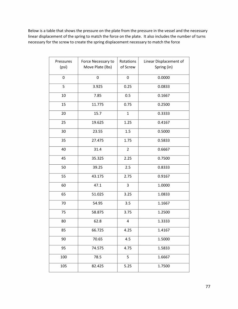
77
Below is a table that shows the pressure on the plate from the pressure in the vessel and the necessary
linear displacement of the spring to match the force on the plate. It also includes the number of turns
necessary for the screw to create the spring displacement necessary to match the force
Pressures
(psi)
Force Necessary to
Move Plate (lbs)
Rotations
of Screw
Linear Displacement of
Spring (in)
0 0 0 0.0000
5 3.925 0.25 0.0833
10 7.85 0.5 0.1667
15 11.775 0.75 0.2500
20 15.7 1 0.3333
25 19.625 1.25 0.4167
30 23.55 1.5 0.5000
35 27.475 1.75 0.5833
40 31.4 2 0.6667
45 35.325 2.25 0.7500
50 39.25 2.5 0.8333
55 43.175 2.75 0.9167
60 47.1 3 1.0000
65 51.025 3.25 1.0833
70 54.95 3.5 1.1667
75 58.875 3.75 1.2500
80 62.8 4 1.3333
85 66.725 4.25 1.4167
90 70.65 4.5 1.5000
95 74.575 4.75 1.5833
100 78.5 5 1.6667
105 82.425 5.25 1.7500
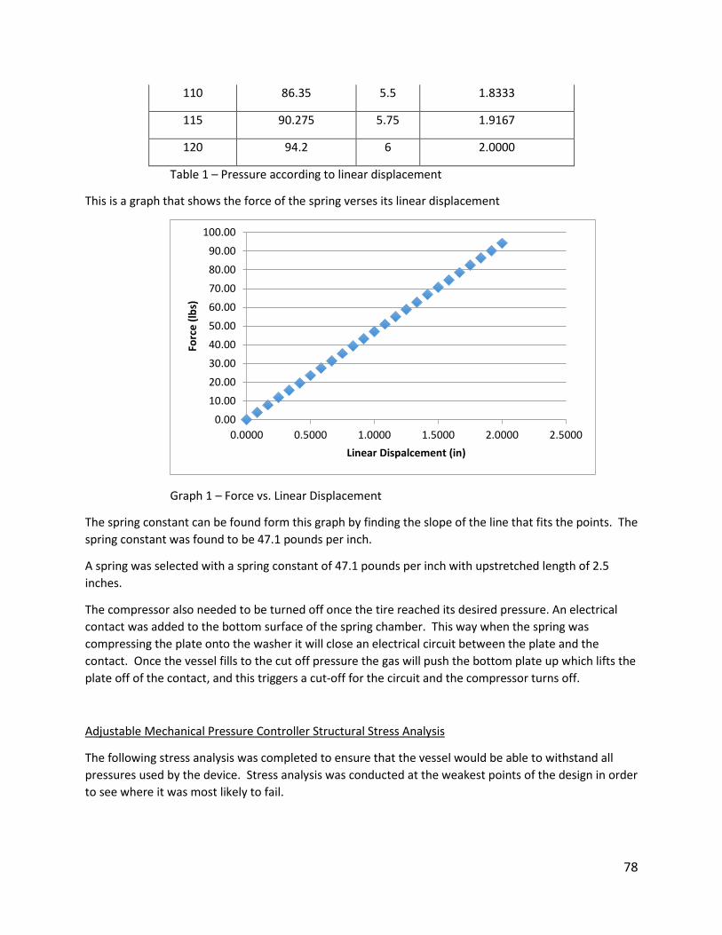
78
110 86.35 5.5 1.8333
115 90.275 5.75 1.9167
120 94.2 6 2.0000
Table 1 – Pressure according to linear displacement
This is a graph that shows the force of the spring verses its linear displacement
Graph 1 – Force vs. Linear Displacement
The spring constant can be found form this graph by finding the slope of the line that fits the points. The
spring constant was found to be 47.1 pounds per inch.
A spring was selected with a spring constant of 47.1 pounds per inch with upstretched length of 2.5
inches.
The compressor also needed to be turned off once the tire reached its desired pressure. An electrical
contact was added to the bottom surface of the spring chamber. This way when the spring was
compressing the plate onto the washer it will close an electrical circuit between the plate and the
contact. Once the vessel fills to the cut off pressure the gas will push the bottom plate up which lifts the
plate off of the contact, and this triggers a cut-off for the circuit and the compressor turns off.
Adjustable Mechanical Pressure Controller Structural Stress Analysis
The following stress analysis was completed to ensure that the vessel would be able to withstand all
pressures used by the device. Stress analysis was conducted at the weakest points of the design in order
to see where it was most likely to fail.
0.00
10.00
20.00
30.00
40.00
50.00
60.00
70.00
80.00
90.00
100.00
0.0000 0.5000 1.0000 1.5000 2.0000 2.5000
Forc
e (
lbs)
Linear Dispalcement (in)
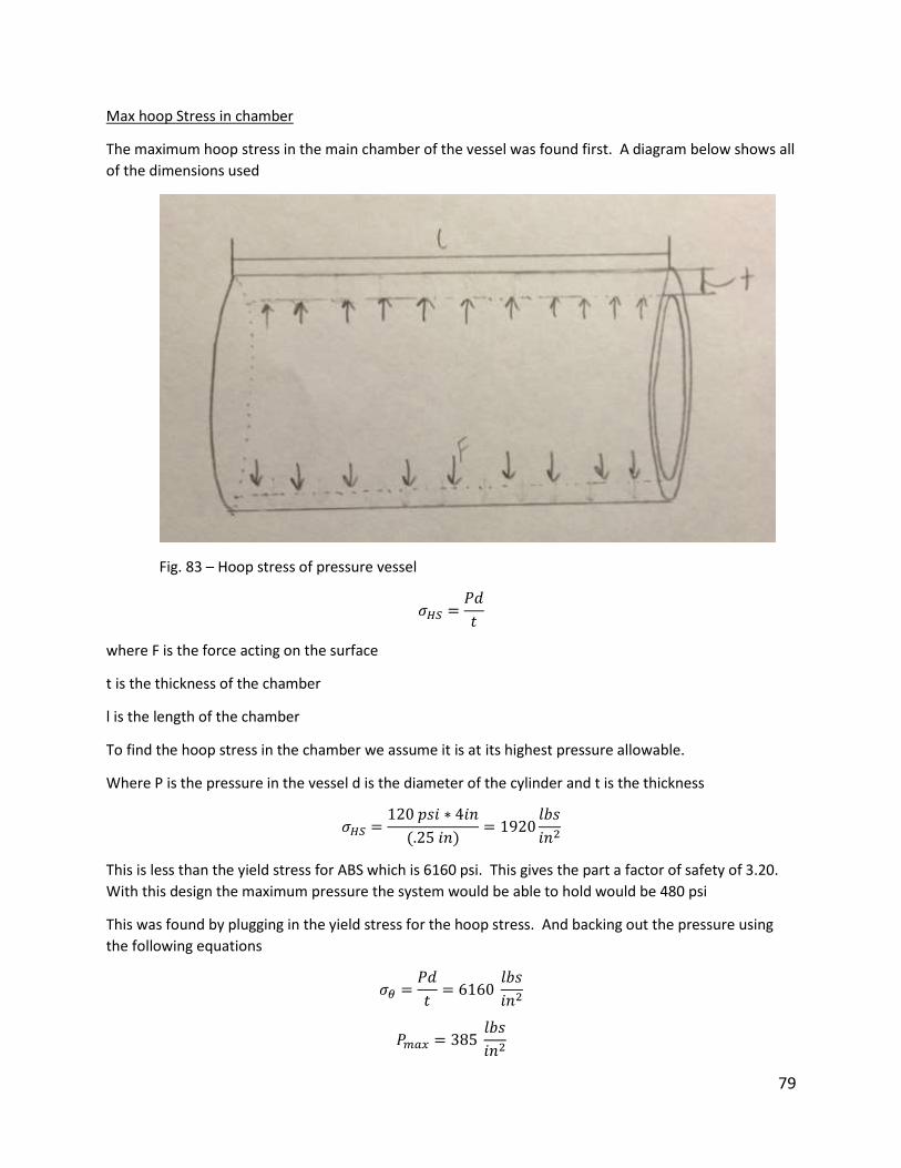
79
Max hoop Stress in chamber
The maximum hoop stress in the main chamber of the vessel was found first. A diagram below shows all
of the dimensions used
Fig. 83 – Hoop stress of pressure vessel
𝜎𝐻𝑆 =𝑃𝑑
𝑡
where F is the force acting on the surface
t is the thickness of the chamber
l is the length of the chamber
To find the hoop stress in the chamber we assume it is at its highest pressure allowable.
Where P is the pressure in the vessel d is the diameter of the cylinder and t is the thickness
𝜎𝐻𝑆 =120 𝑝𝑠𝑖 ∗ 4𝑖𝑛
(.25 𝑖𝑛)= 1920
𝑙𝑏𝑠
𝑖𝑛2
This is less than the yield stress for ABS which is 6160 psi. This gives the part a factor of safety of 3.20.
With this design the maximum pressure the system would be able to hold would be 480 psi
This was found by plugging in the yield stress for the hoop stress. And backing out the pressure using
the following equations
𝜎𝜃 =𝑃𝑑
𝑡= 6160
𝑙𝑏𝑠
𝑖𝑛2
𝑃𝑚𝑎𝑥 = 385 𝑙𝑏𝑠
𝑖𝑛2
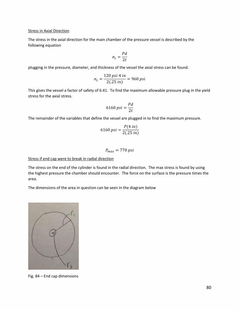
80
Stress in Axial Direction
The stress in the axial direction for the main chamber of the pressure vessel is described by the
following equation
𝜎𝐿 =𝑃𝑑
2𝑡
plugging in the pressure, diameter, and thickness of the vessel the axial stress can be found.
𝜎𝐿 =120 𝑝𝑠𝑖 4 𝑖𝑛
2(.25 𝑖𝑛)= 960 𝑝𝑠𝑖
This gives the vessel a factor of safety of 6.41. To find the maximum allowable pressure plug in the yield
stress for the axial stress.
6160 𝑝𝑠𝑖 =𝑃𝑑
2𝑡
The remainder of the variables that define the vessel are plugged in to find the maximum pressure.
6160 𝑝𝑠𝑖 =𝑃(4 𝑖𝑛)
2(.25 𝑖𝑛)
𝑃𝑚𝑎𝑥 = 770 𝑝𝑠𝑖
Stress if end cap were to break in radial direction
The stress on the end of the cylinder is found in the radial direction. The max stress is found by using
the highest pressure the chamber should encounter. The force on the surface is the pressure times the
area.
The dimensions of the area in question can be seen in the diagram below
Fig. 84 – End cap dimensions
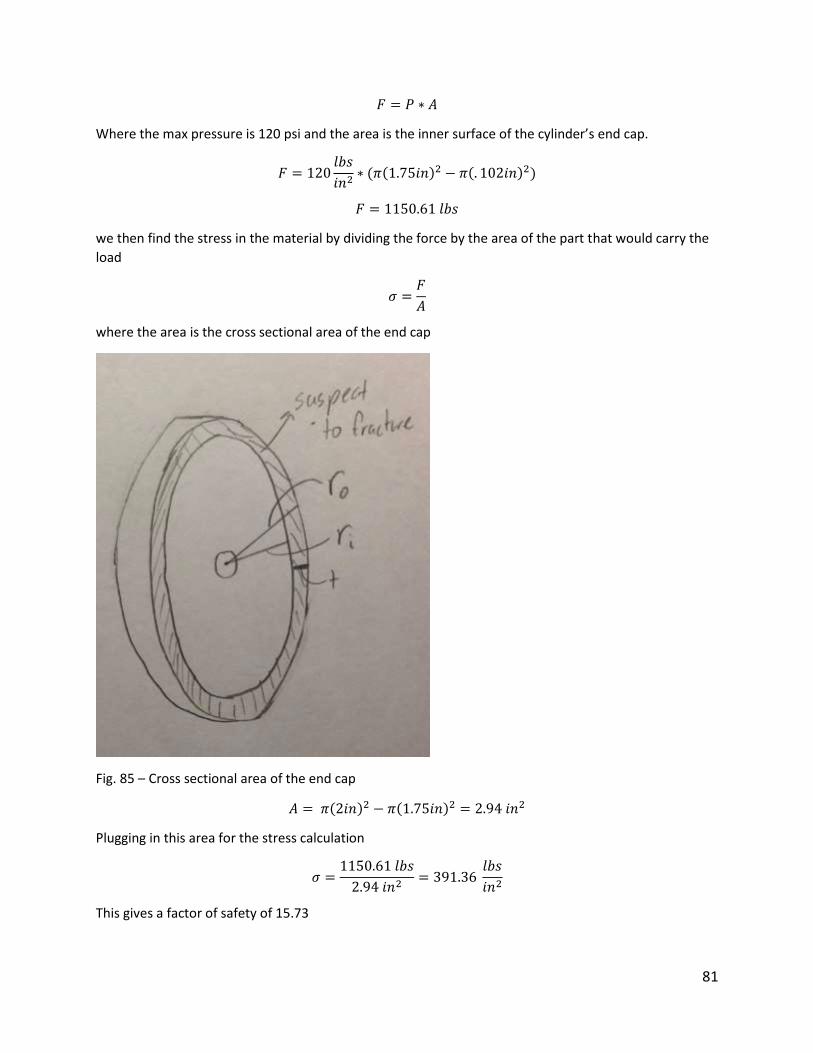
81
𝐹 = 𝑃 ∗ 𝐴
Where the max pressure is 120 psi and the area is the inner surface of the cylinder’s end cap.
𝐹 = 120𝑙𝑏𝑠
𝑖𝑛2∗ (𝜋(1.75𝑖𝑛)2 − 𝜋(. 102𝑖𝑛)2)
𝐹 = 1150.61 𝑙𝑏𝑠
we then find the stress in the material by dividing the force by the area of the part that would carry the
load
𝜎 =𝐹
𝐴
where the area is the cross sectional area of the end cap
Fig. 85 – Cross sectional area of the end cap
𝐴 = 𝜋(2𝑖𝑛)2 − 𝜋(1.75𝑖𝑛)2 = 2.94 𝑖𝑛2
Plugging in this area for the stress calculation
𝜎 =1150.61 𝑙𝑏𝑠
2.94 𝑖𝑛2= 391.36
𝑙𝑏𝑠
𝑖𝑛2
This gives a factor of safety of 15.73
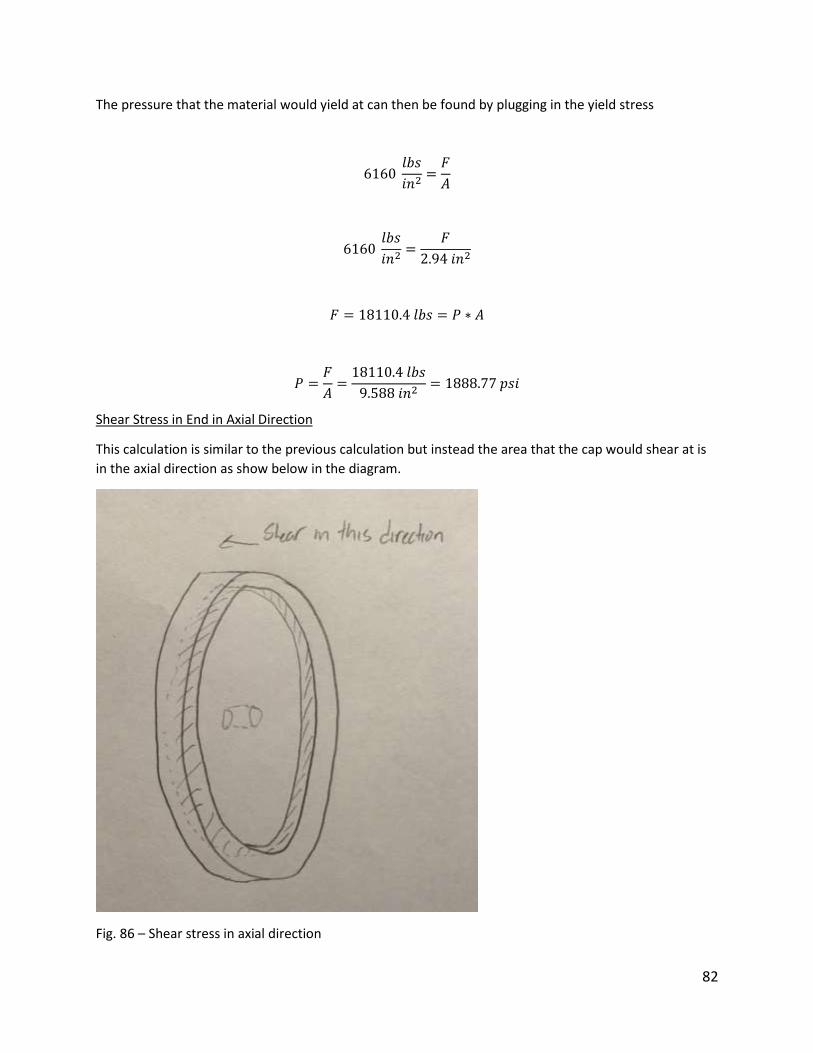
82
The pressure that the material would yield at can then be found by plugging in the yield stress
6160 𝑙𝑏𝑠
𝑖𝑛2=𝐹
𝐴
6160 𝑙𝑏𝑠
𝑖𝑛2=
𝐹
2.94 𝑖𝑛2
𝐹 = 18110.4 𝑙𝑏𝑠 = 𝑃 ∗ 𝐴
𝑃 =𝐹
𝐴=18110.4 𝑙𝑏𝑠
9.588 𝑖𝑛2= 1888.77 𝑝𝑠𝑖
Shear Stress in End in Axial Direction
This calculation is similar to the previous calculation but instead the area that the cap would shear at is
in the axial direction as show below in the diagram.
Fig. 86 – Shear stress in axial direction
83
The force is calculated the same way as the previous calculation
𝐹 = 120𝑙𝑏𝑠
𝑖𝑛2∗ (𝜋(1.75𝑖𝑛)2 − 𝜋(. 102𝑖𝑛)2)
𝐹 = 1150.61 𝑙𝑏𝑠
The area that would shear in the axial direction is now calculated.
[area of stress applied to axial direction]
𝐴𝑟𝑒𝑎 = 2𝜋𝑟𝑤
𝐴𝑟𝑒𝑎 = 2𝜋(1.75 𝑖𝑛)(. 25 𝑖𝑛) = 2.74 𝑖𝑛2
The stress on the part is then calculated by dividing the force by the area that is being sheered.
𝜎 =1150.61 𝑙𝑏𝑠
2.74 𝑖𝑛2= 419.93
𝑙𝑏𝑠
𝑖𝑛2
This gives this part a factor of safety of 14.66
Next the maximum pressure the part could handle is calculated.
𝜎 =𝐹
𝐴= 6169
𝑙𝑏𝑠
𝑖𝑛2
𝐹 = 𝜎 ∗ 𝐴 = 6169𝑙𝑏𝑠
𝑖𝑛2∗ 2.74 𝑖𝑛2 = 16903.06 𝑙𝑏𝑠
𝑃 =𝐹
𝐴=16903.06 𝑙𝑏𝑠
9.588 𝑖𝑛2= 1762.93 𝑝𝑠𝑖
This means the wall would not shear in the axial direction until a pressure of 1762.93 psi was reached
which is well above our maximum desired pressure.
Hoop Stress in End Fittings
This is one of the smaller dimensioned pieces for the pressure regulator, therefore stress analysis must
be done on the part to ensure it will be able to withstand any stresses it encounters over the life of the
part.
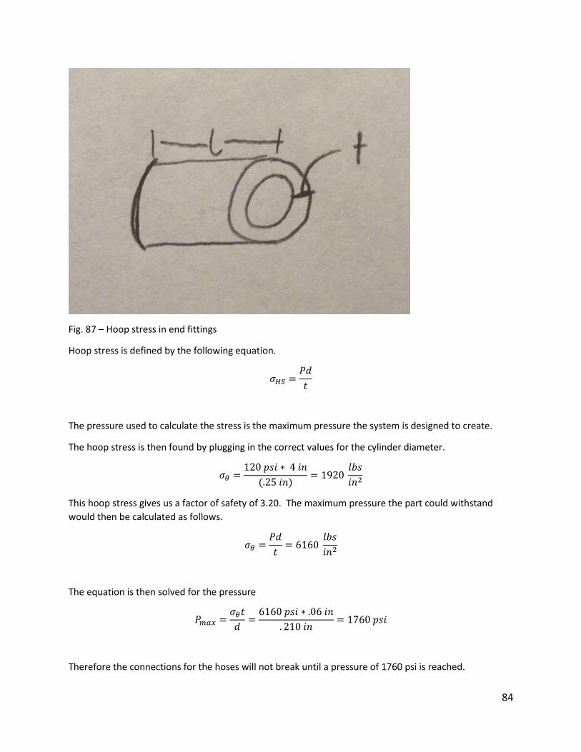
84
Fig. 87 – Hoop stress in end fittings
Hoop stress is defined by the following equation.
𝜎𝐻𝑆 =𝑃𝑑
𝑡
The pressure used to calculate the stress is the maximum pressure the system is designed to create.
The hoop stress is then found by plugging in the correct values for the cylinder diameter.
𝜎𝜃 =120 𝑝𝑠𝑖 ∗ 4 𝑖𝑛
(.25 𝑖𝑛)= 1920
𝑙𝑏𝑠
𝑖𝑛2
This hoop stress gives us a factor of safety of 3.20. The maximum pressure the part could withstand
would then be calculated as follows.
𝜎𝜃 =𝑃𝑑
𝑡= 6160
𝑙𝑏𝑠
𝑖𝑛2
The equation is then solved for the pressure
𝑃𝑚𝑎𝑥 =𝜎𝜃𝑡
𝑑=6160 𝑝𝑠𝑖 ∗ .06 𝑖𝑛
. 210 𝑖𝑛= 1760 𝑝𝑠𝑖
Therefore the connections for the hoses will not break until a pressure of 1760 psi is reached.
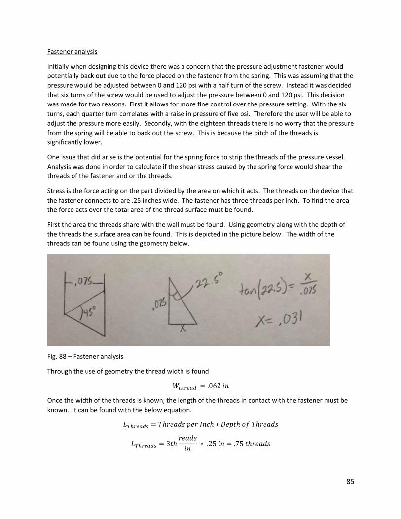
85
Fastener analysis
Initially when designing this device there was a concern that the pressure adjustment fastener would
potentially back out due to the force placed on the fastener from the spring. This was assuming that the
pressure would be adjusted between 0 and 120 psi with a half turn of the screw. Instead it was decided
that six turns of the screw would be used to adjust the pressure between 0 and 120 psi. This decision
was made for two reasons. First it allows for more fine control over the pressure setting. With the six
turns, each quarter turn correlates with a raise in pressure of five psi. Therefore the user will be able to
adjust the pressure more easily. Secondly, with the eighteen threads there is no worry that the pressure
from the spring will be able to back out the screw. This is because the pitch of the threads is
significantly lower.
One issue that did arise is the potential for the spring force to strip the threads of the pressure vessel.
Analysis was done in order to calculate if the shear stress caused by the spring force would shear the
threads of the fastener and or the threads.
Stress is the force acting on the part divided by the area on which it acts. The threads on the device that
the fastener connects to are .25 inches wide. The fastener has three threads per inch. To find the area
the force acts over the total area of the thread surface must be found.
First the area the threads share with the wall must be found. Using geometry along with the depth of
the threads the surface area can be found. This is depicted in the picture below. The width of the
threads can be found using the geometry below.
Fig. 88 – Fastener analysis
Through the use of geometry the thread width is found
𝑊𝑡ℎ𝑟𝑒𝑎𝑑 = .062 𝑖𝑛
Once the width of the threads is known, the length of the threads in contact with the fastener must be
known. It can be found with the below equation.
𝐿𝑇ℎ𝑟𝑒𝑎𝑑𝑠 = 𝑇ℎ𝑟𝑒𝑎𝑑𝑠 𝑝𝑒𝑟 𝐼𝑛𝑐ℎ ∗ 𝐷𝑒𝑝𝑡ℎ 𝑜𝑓 𝑇ℎ𝑟𝑒𝑎𝑑𝑠
𝐿𝑇ℎ𝑟𝑒𝑎𝑑𝑠 = 3𝑡ℎ𝑟𝑒𝑎𝑑𝑠
𝑖𝑛 ∗ .25 𝑖𝑛 = .75 𝑡ℎ𝑟𝑒𝑎𝑑𝑠
86
The number of threads is then used to calculate the length of threads in contact with the fastener. Each
thread has a surface area of a cylinder with the minor diameter of the fastener.
𝐴𝑟𝑒𝑎 = 𝜋 ∗ 𝐷 ∗ 𝑊𝑡ℎ𝑟𝑒𝑎𝑑
𝐴𝑟𝑒𝑎 = 𝜋 ∗ .75 𝑖𝑛 ∗ .062 𝑖𝑛 = .10956 𝑖𝑛2
The stress induced in the threads by the spring force is then found with the following equation.
𝜎 =𝐹
𝐴=(120 𝑝𝑠𝑖) ∗ (.7853 𝑖𝑛2)
. 10956 𝑖𝑛2= 860.10 𝑝𝑠𝑖
The stress found was 860.1 psi which is well below the maximum yield stress of 6160 psi. This gives a
factor of safety of 7.16.
Next the pressure the threads will be stripped at is found. The yield stress is plugged into the following
equation to determine the force required to strip the threads.
6160 𝑝𝑠𝑖 =𝐹
. 10956 𝑖𝑛2
𝐹 = 674.88 𝑙𝑏𝑠
This force is then used to calculate the pressure necessary on the plate, which will push on the spring
and then on the top plate and fastener.
𝐹 = 𝑃 ∗ 𝐴
674.88 𝑙𝑏𝑠 = 𝑃 ∗ .7853 𝑖𝑛2
𝑃 = 859.39 𝑝𝑠𝑖
This is well above the maximum expected pressure and should never be encountered by the device.
Vessel Expansion Calculations
Calculations were performed to ensure the expansion in the vessel was at an acceptable level. The
change in the radius of the vessel was calculated using the following formula.
𝑐ℎ𝑎𝑛𝑔𝑒 𝑖𝑠 𝑟𝑎𝑑𝑖𝑢𝑠 = 𝑃𝑟𝑖𝐸
(
1 +
𝑟𝑖2
𝑟𝑜2
1 −𝑟𝑖2
𝑟𝑜2
+ 𝜐
)
Where P is the pressure in the vessel, 𝑟𝑖 is the inner radius of the vessel, 𝑟𝑜 is the outer diameter of the
vessel, E is the young’s modulus of ABS, and 𝜐 is the poisson’s ratio of ABS. The change in radius can be
seen below calculated by plugging in appropriate numbers.
𝑐ℎ𝑎𝑛𝑔𝑒 𝑖𝑠 𝑟𝑎𝑑𝑖𝑢𝑠 = 120 𝑝𝑠𝑖 ∗ 1.75 𝑖𝑛
3.80 × 10⁵(1 +
1.752
22
1 −1.752
22
+ .35) = .004 𝑖𝑛𝑐ℎ𝑒𝑠

87
Therefore the radius will expand by .004 inches. This radial expansion can be used to calculate the
change in the pressure release hole. Using the geometry shown below the expansion in the hole is
calculated.
Using similar triangles, the new gap can be determined. The geometry is shown in the picture below
Fig. 89 – Fastener analysis
The new hole with the expanded cylinder has a diameter of 1.02 inches. The gasket that fills the gap is
more than thick enough to ensure the expansion will be accounted for.
Blow Off Valve Gasket Analysis
Initially there was concern that friction might be generated by the gasket that seals the vessel. The new
design has a gasket that is attached to the vessel where the pressure release valve is. Therefore the
gasket does not move and no friction is generated. This is because friction force is given by the
equation below.
𝐹𝑓𝑟𝑖𝑐𝑡𝑖𝑜𝑛 = 𝜇𝐹𝑁
This equation states that the friction force is generated by the normal force multiplied by a known
friction coefficient between the two materials. Because all of the force being exerted on the gasket is in
the vertical direction no normal force is generated to rub the gasket on the sides of the cylinder.
Therefore no friction force is generated to impede the movement of the plate.
Fatigue analysis
Analysis was done in order to determine the number of life cycles that the vessel would be able to go
through before it would cause failure. The vessel material is ABS and was treated as a ductile material.
With a wall thickness of .25 inches and a maximum pressure allowable of 120 psi the life span of the
vessel was assumed to be infinite but calculations were done to do verify this.
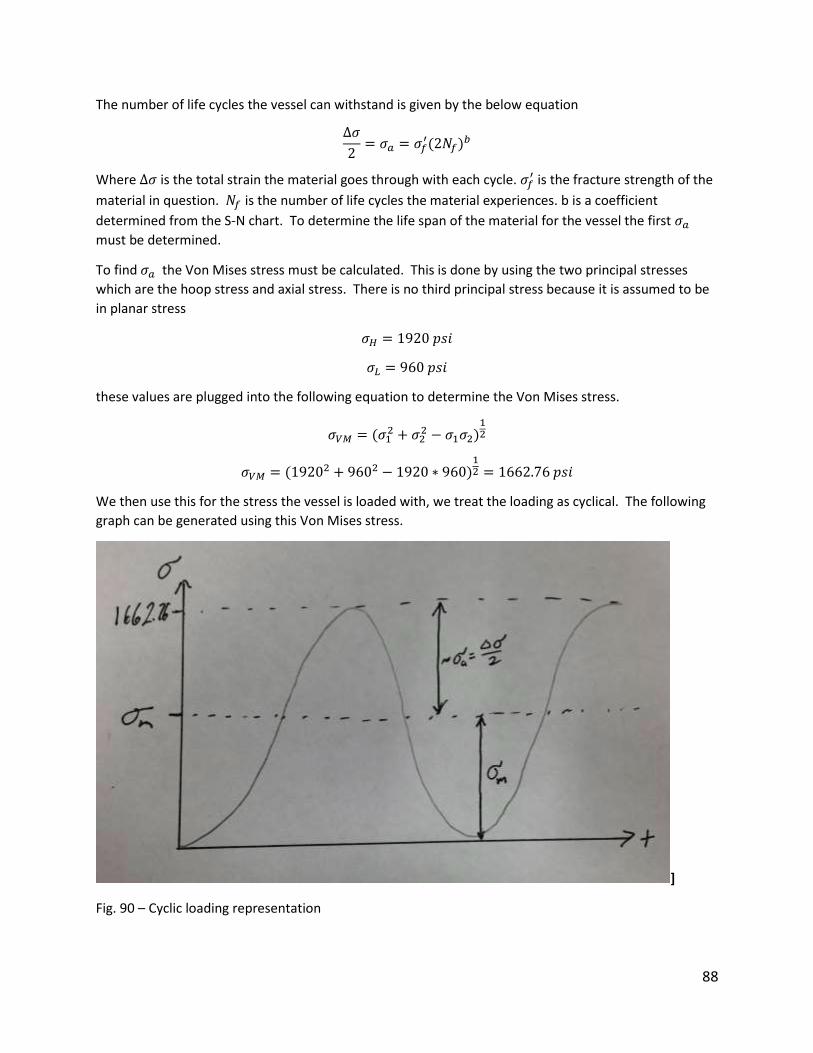
88
The number of life cycles the vessel can withstand is given by the below equation
∆𝜎
2= 𝜎𝑎 = 𝜎𝑓
′(2𝑁𝑓)𝑏
Where ∆𝜎 is the total strain the material goes through with each cycle. 𝜎𝑓′ is the fracture strength of the
material in question. 𝑁𝑓 is the number of life cycles the material experiences. b is a coefficient
determined from the S-N chart. To determine the life span of the material for the vessel the first 𝜎𝑎
must be determined.
To find 𝜎𝑎 the Von Mises stress must be calculated. This is done by using the two principal stresses
which are the hoop stress and axial stress. There is no third principal stress because it is assumed to be
in planar stress
𝜎𝐻 = 1920 𝑝𝑠𝑖
𝜎𝐿 = 960 𝑝𝑠𝑖
these values are plugged into the following equation to determine the Von Mises stress.
𝜎𝑉𝑀 = (𝜎12 + 𝜎2
2 − 𝜎1𝜎2)12
𝜎𝑉𝑀 = (19202 + 9602 − 1920 ∗ 960)
12 = 1662.76 𝑝𝑠𝑖
We then use this for the stress the vessel is loaded with, we treat the loading as cyclical. The following
graph can be generated using this Von Mises stress.
]
Fig. 90 – Cyclic loading representation
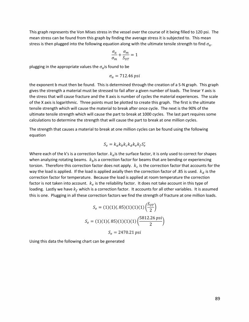
89
This graph represents the Von Mises stress in the vessel over the course of it being filled to 120 psi. The
mean stress can be found from this graph by finding the average stress it is subjected to. This mean
stress is then plugged into the following equation along with the ultimate tensile strength to find 𝜎𝑎.
𝜎𝑎𝜎𝑚+𝜎𝑚𝑆𝑈𝑇
= 1
plugging in the appropriate values the 𝜎𝑎is found to be
𝜎𝑎 = 712.46 𝑝𝑠𝑖
the exponent b must then be found. This is determined through the creation of a S-N graph. This graph
gives the strength a material must be stressed to fail after a given number of loads. The linear Y axis is
the stress that will cause fracture and the X axis is number of cycles the material experiences. The scale
of the X axis is logarithmic. Three points must be plotted to create this graph. The first is the ultimate
tensile strength which will cause the material to break after once cycle. The next is the 90% of the
ultimate tensile strength which will cause the part to break at 1000 cycles. The last part requires some
calculations to determine the strength that will cause the part to break at one million cycles.
The strength that causes a material to break at one million cycles can be found using the following
equation
𝑆𝑒 = 𝑘𝑎𝑘𝑏𝑘𝑐𝑘𝑑𝑘𝑒𝑘𝑓𝑆𝑒′
Where each of the k’s is a correction factor. 𝑘𝑎is the surface factor, it is only used to correct for shapes
when analyzing rotating beams. 𝑘𝑏is a correction factor for beams that are bending or experiencing
torsion. Therefore this correction factor does not apply. 𝑘𝑐 is the correction factor that accounts for the
way the load is applied. If the load is applied axially then the correction factor of .85 is used. 𝑘𝑑 is the
correction factor for temperature. Because the load is applied at room temperature the correction
factor is not taken into account. 𝑘𝑒 is the reliability factor. It does not take account in this type of
loading. Lastly we have 𝑘𝑓 which is a correction factor. It accounts for all other variables. It is assumed
this is one. Plugging in all these correction factors we find the strength of fracture at one million loads.
𝑆𝑒 = (1)(1)(. 85)(1)(1)(1) (𝑆𝑈𝑇2)
𝑆𝑒 = (1)(1)(. 85)(1)(1)(1) (5812.26 𝑝𝑠𝑖
2)
𝑆𝑒 = 2470.21 𝑝𝑠𝑖
Using this data the following chart can be generated
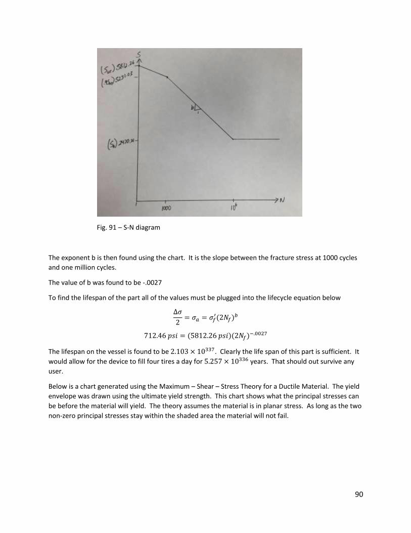
90
Fig. 91 – S-N diagram
The exponent b is then found using the chart. It is the slope between the fracture stress at 1000 cycles
and one million cycles.
The value of b was found to be -.0027
To find the lifespan of the part all of the values must be plugged into the lifecycle equation below
∆𝜎
2= 𝜎𝑎 = 𝜎𝑓
′(2𝑁𝑓)𝑏
712.46 𝑝𝑠𝑖 = (5812.26 𝑝𝑠𝑖)(2𝑁𝑓)−.0027
The lifespan on the vessel is found to be 2.103 × 10337. Clearly the life span of this part is sufficient. It
would allow for the device to fill four tires a day for 5.257 × 10336 years. That should out survive any
user.
Below is a chart generated using the Maximum – Shear – Stress Theory for a Ductile Material. The yield
envelope was drawn using the ultimate yield strength. This chart shows what the principal stresses can
be before the material will yield. The theory assumes the material is in planar stress. As long as the two
non-zero principal stresses stay within the shaded area the material will not fail.
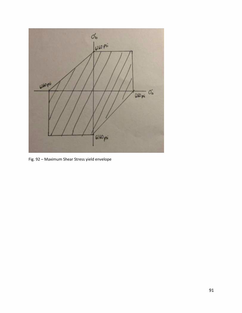
91
Fig. 92 – Maximum Shear Stress yield envelope
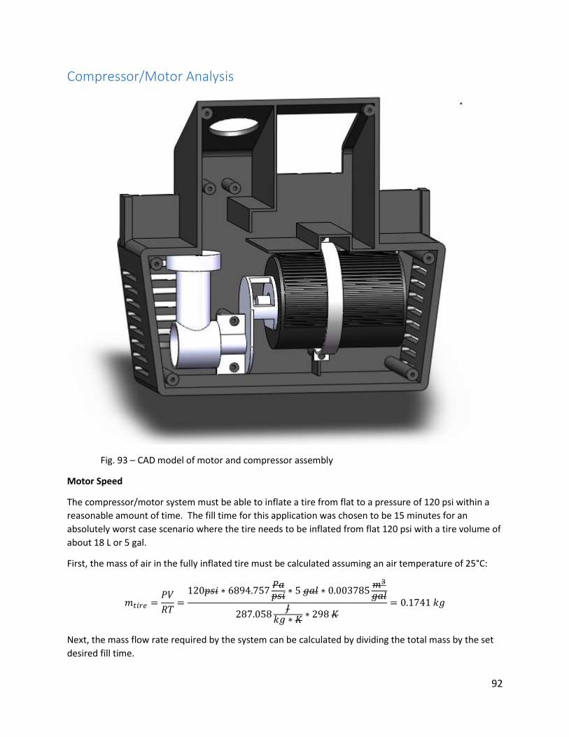
92
Compressor/Motor Analysis
Fig. 93 – CAD model of motor and compressor assembly
Motor Speed
The compressor/motor system must be able to inflate a tire from flat to a pressure of 120 psi within a
reasonable amount of time. The fill time for this application was chosen to be 15 minutes for an
absolutely worst case scenario where the tire needs to be inflated from flat 120 psi with a tire volume of
about 18 L or 5 gal.
First, the mass of air in the fully inflated tire must be calculated assuming an air temperature of 25°C:
𝑚𝑡𝑖𝑟𝑒 =𝑃𝑉
𝑅𝑇=120𝑝𝑠𝑖 ∗ 6894.757
𝑃𝑎𝑝𝑠𝑖 ∗ 5 𝑔𝑎𝑙 ∗ 0.003785
𝑚3
𝑔𝑎𝑙
287.058𝐽
𝑘𝑔 ∗ 𝐾∗ 298 𝐾
= 0.1741 𝑘𝑔
Next, the mass flow rate required by the system can be calculated by dividing the total mass by the set
desired fill time.
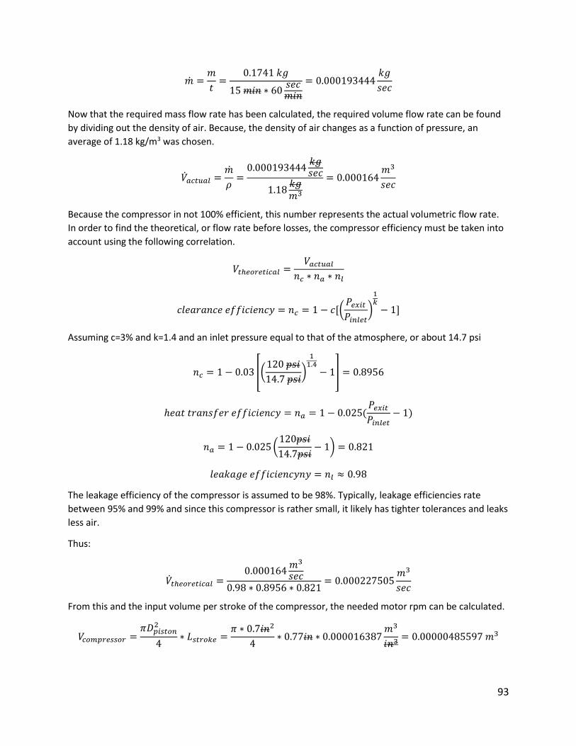
93
�̇� =𝑚
𝑡=
0.1741 𝑘𝑔
15 𝑚𝑖𝑛 ∗ 60𝑠𝑒𝑐𝑚𝑖𝑛
= 0.000193444𝑘𝑔
𝑠𝑒𝑐
Now that the required mass flow rate has been calculated, the required volume flow rate can be found
by dividing out the density of air. Because, the density of air changes as a function of pressure, an
average of 1.18 kg/m3 was chosen.
�̇�𝑎𝑐𝑡𝑢𝑎𝑙 =�̇�
𝜌=0.000193444
𝑘𝑔𝑠𝑒𝑐
1.18𝑘𝑔𝑚3
= 0.000164𝑚3
𝑠𝑒𝑐
Because the compressor in not 100% efficient, this number represents the actual volumetric flow rate.
In order to find the theoretical, or flow rate before losses, the compressor efficiency must be taken into
account using the following correlation.
𝑉𝑡ℎ𝑒𝑜𝑟𝑒𝑡𝑖𝑐𝑎𝑙 =𝑉𝑎𝑐𝑡𝑢𝑎𝑙
𝑛𝑐 ∗ 𝑛𝑎 ∗ 𝑛𝑙
𝑐𝑙𝑒𝑎𝑟𝑎𝑛𝑐𝑒 𝑒𝑓𝑓𝑖𝑐𝑖𝑒𝑛𝑐𝑦 = 𝑛𝑐 = 1 − 𝑐[(𝑃𝑒𝑥𝑖𝑡𝑃𝑖𝑛𝑙𝑒𝑡
)
1𝑘− 1]
Assuming c=3% and k=1.4 and an inlet pressure equal to that of the atmosphere, or about 14.7 psi
𝑛𝑐 = 1 − 0.03 [(120 𝑝𝑠𝑖
14.7 𝑝𝑠𝑖)
11.4− 1] = 0.8956
ℎ𝑒𝑎𝑡 𝑡𝑟𝑎𝑛𝑠𝑓𝑒𝑟 𝑒𝑓𝑓𝑖𝑐𝑖𝑒𝑛𝑐𝑦 = 𝑛𝑎 = 1 − 0.025(𝑃𝑒𝑥𝑖𝑡𝑃𝑖𝑛𝑙𝑒𝑡
− 1)
𝑛𝑎 = 1 − 0.025(120𝑝𝑠𝑖
14.7𝑝𝑠𝑖− 1) = 0.821
𝑙𝑒𝑎𝑘𝑎𝑔𝑒 𝑒𝑓𝑓𝑖𝑐𝑖𝑒𝑛𝑐𝑦𝑛𝑦 = 𝑛𝑙 ≈ 0.98
The leakage efficiency of the compressor is assumed to be 98%. Typically, leakage efficiencies rate
between 95% and 99% and since this compressor is rather small, it likely has tighter tolerances and leaks
less air.
Thus:
�̇�𝑡ℎ𝑒𝑜𝑟𝑒𝑡𝑖𝑐𝑎𝑙 =0.000164
𝑚3
𝑠𝑒𝑐0.98 ∗ 0.8956 ∗ 0.821
= 0.000227505𝑚3
𝑠𝑒𝑐
From this and the input volume per stroke of the compressor, the needed motor rpm can be calculated.
𝑉𝑐𝑜𝑚𝑝𝑟𝑒𝑠𝑠𝑜𝑟 =𝜋𝐷𝑝𝑖𝑠𝑡𝑜𝑛
2
4∗ 𝐿𝑠𝑡𝑟𝑜𝑘𝑒 =
𝜋 ∗ 0.7𝑖𝑛2
4∗ 0.77𝑖𝑛 ∗ 0.000016387
𝑚3
𝑖𝑛3= 0.00000485597 𝑚3
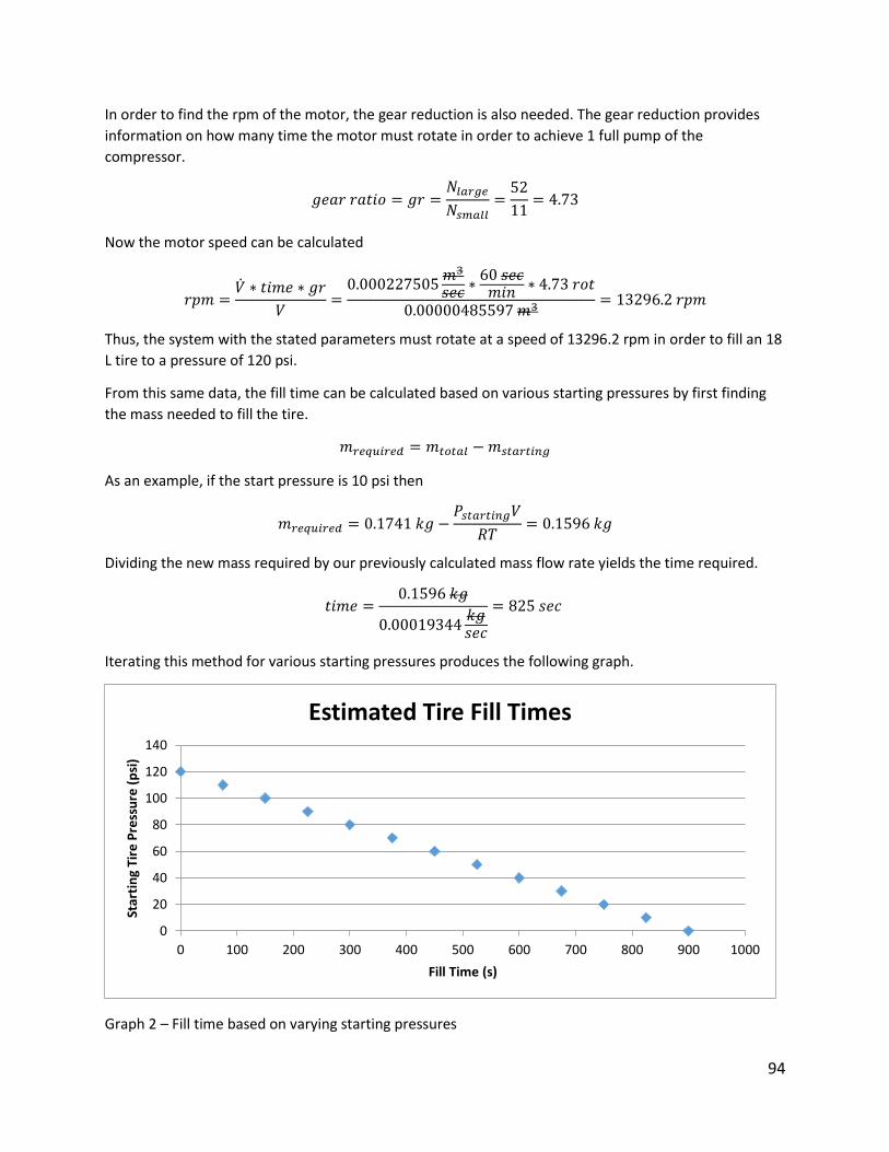
94
In order to find the rpm of the motor, the gear reduction is also needed. The gear reduction provides
information on how many time the motor must rotate in order to achieve 1 full pump of the
compressor.
𝑔𝑒𝑎𝑟 𝑟𝑎𝑡𝑖𝑜 = 𝑔𝑟 =𝑁𝑙𝑎𝑟𝑔𝑒
𝑁𝑠𝑚𝑎𝑙𝑙=52
11= 4.73
Now the motor speed can be calculated
𝑟𝑝𝑚 =�̇� ∗ 𝑡𝑖𝑚𝑒 ∗ 𝑔𝑟
𝑉=0.000227505
𝑚3
𝑠𝑒𝑐∗60 𝑠𝑒𝑐𝑚𝑖𝑛
∗ 4.73 𝑟𝑜𝑡
0.00000485597 𝑚3= 13296.2 𝑟𝑝𝑚
Thus, the system with the stated parameters must rotate at a speed of 13296.2 rpm in order to fill an 18
L tire to a pressure of 120 psi.
From this same data, the fill time can be calculated based on various starting pressures by first finding
the mass needed to fill the tire.
𝑚𝑟𝑒𝑞𝑢𝑖𝑟𝑒𝑑 = 𝑚𝑡𝑜𝑡𝑎𝑙 −𝑚𝑠𝑡𝑎𝑟𝑡𝑖𝑛𝑔
As an example, if the start pressure is 10 psi then
𝑚𝑟𝑒𝑞𝑢𝑖𝑟𝑒𝑑 = 0.1741 𝑘𝑔 −𝑃𝑠𝑡𝑎𝑟𝑡𝑖𝑛𝑔𝑉
𝑅𝑇= 0.1596 𝑘𝑔
Dividing the new mass required by our previously calculated mass flow rate yields the time required.
𝑡𝑖𝑚𝑒 =0.1596 𝑘𝑔
0.00019344𝑘𝑔𝑠𝑒𝑐
= 825 𝑠𝑒𝑐
Iterating this method for various starting pressures produces the following graph.
Graph 2 – Fill time based on varying starting pressures
0
20
40
60
80
100
120
140
0 100 200 300 400 500 600 700 800 900 1000
Star
tin
g Ti
re P
ress
ure
(p
si)
Fill Time (s)
Estimated Tire Fill Times
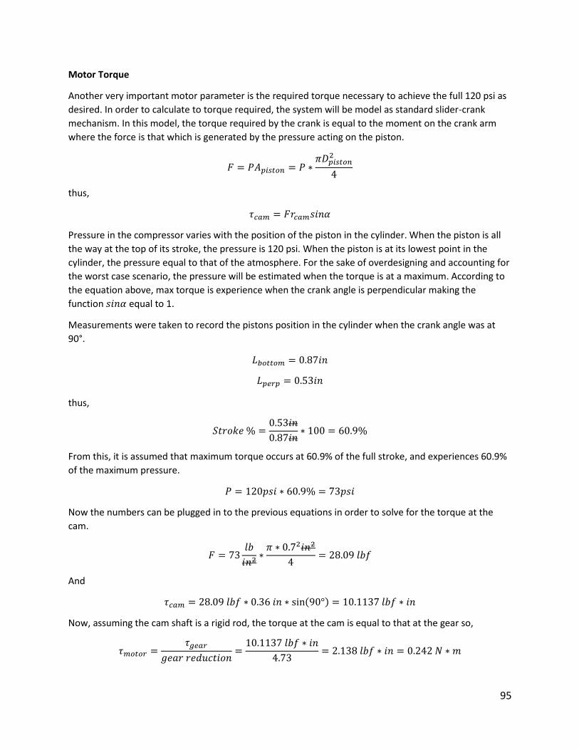
95
Motor Torque
Another very important motor parameter is the required torque necessary to achieve the full 120 psi as
desired. In order to calculate to torque required, the system will be model as standard slider-crank
mechanism. In this model, the torque required by the crank is equal to the moment on the crank arm
where the force is that which is generated by the pressure acting on the piston.
𝐹 = 𝑃𝐴𝑝𝑖𝑠𝑡𝑜𝑛 = 𝑃 ∗𝜋𝐷𝑝𝑖𝑠𝑡𝑜𝑛
2
4
thus,
𝜏𝑐𝑎𝑚 = 𝐹𝑟𝑐𝑎𝑚𝑠𝑖𝑛𝛼
Pressure in the compressor varies with the position of the piston in the cylinder. When the piston is all
the way at the top of its stroke, the pressure is 120 psi. When the piston is at its lowest point in the
cylinder, the pressure equal to that of the atmosphere. For the sake of overdesigning and accounting for
the worst case scenario, the pressure will be estimated when the torque is at a maximum. According to
the equation above, max torque is experience when the crank angle is perpendicular making the
function 𝑠𝑖𝑛𝛼 equal to 1.
Measurements were taken to record the pistons position in the cylinder when the crank angle was at
90°.
𝐿𝑏𝑜𝑡𝑡𝑜𝑚 = 0.87𝑖𝑛
𝐿𝑝𝑒𝑟𝑝 = 0.53𝑖𝑛
thus,
𝑆𝑡𝑟𝑜𝑘𝑒 % =0.53𝑖𝑛
0.87𝑖𝑛∗ 100 = 60.9%
From this, it is assumed that maximum torque occurs at 60.9% of the full stroke, and experiences 60.9%
of the maximum pressure.
𝑃 = 120𝑝𝑠𝑖 ∗ 60.9% = 73𝑝𝑠𝑖
Now the numbers can be plugged in to the previous equations in order to solve for the torque at the
cam.
𝐹 = 73𝑙𝑏
𝑖𝑛2∗𝜋 ∗ 0.72𝑖𝑛2
4= 28.09 𝑙𝑏𝑓
And
𝜏𝑐𝑎𝑚 = 28.09 𝑙𝑏𝑓 ∗ 0.36 𝑖𝑛 ∗ sin(90°) = 10.1137 𝑙𝑏𝑓 ∗ 𝑖𝑛
Now, assuming the cam shaft is a rigid rod, the torque at the cam is equal to that at the gear so,
𝜏𝑚𝑜𝑡𝑜𝑟 =𝜏𝑔𝑒𝑎𝑟
𝑔𝑒𝑎𝑟 𝑟𝑒𝑑𝑢𝑐𝑡𝑖𝑜𝑛=10.1137 𝑙𝑏𝑓 ∗ 𝑖𝑛
4.73= 2.138 𝑙𝑏𝑓 ∗ 𝑖𝑛 = 0.242 𝑁 ∗ 𝑚
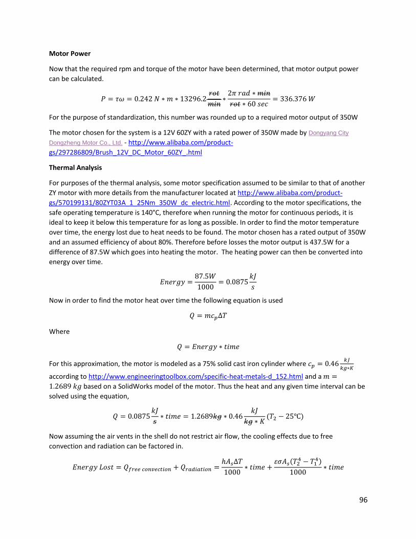
96
Motor Power
Now that the required rpm and torque of the motor have been determined, that motor output power
can be calculated.
𝑃 = 𝜏𝜔 = 0.242 𝑁 ∗ 𝑚 ∗ 13296.2𝑟𝑜𝑡
𝑚𝑖𝑛∗2𝜋 𝑟𝑎𝑑 ∗ 𝑚𝑖𝑛
𝑟𝑜𝑡 ∗ 60 𝑠𝑒𝑐= 336.376 𝑊
For the purpose of standardization, this number was rounded up to a required motor output of 350W
The motor chosen for the system is a 12V 60ZY with a rated power of 350W made by Dongyang City
Dongzheng Motor Co., Ltd. - http://www.alibaba.com/product-
gs/297286809/Brush_12V_DC_Motor_60ZY_.html
Thermal Analysis
For purposes of the thermal analysis, some motor specification assumed to be similar to that of another
ZY motor with more details from the manufacturer located at http://www.alibaba.com/product-
gs/570199131/80ZYT03A_1_25Nm_350W_dc_electric.html. According to the motor specifications, the
safe operating temperature is 140°C, therefore when running the motor for continuous periods, it is
ideal to keep it below this temperature for as long as possible. In order to find the motor temperature
over time, the energy lost due to heat needs to be found. The motor chosen has a rated output of 350W
and an assumed efficiency of about 80%. Therefore before losses the motor output is 437.5W for a
difference of 87.5W which goes into heating the motor. The heating power can then be converted into
energy over time.
𝐸𝑛𝑒𝑟𝑔𝑦 =87.5𝑊
1000= 0.0875
𝑘𝐽
𝑠
Now in order to find the motor heat over time the following equation is used
𝑄 = 𝑚𝑐𝑝∆𝑇
Where
𝑄 = 𝐸𝑛𝑒𝑟𝑔𝑦 ∗ 𝑡𝑖𝑚𝑒
For this approximation, the motor is modeled as a 75% solid cast iron cylinder where 𝑐𝑝 = 0.46𝑘𝐽
𝑘𝑔∗𝐾
according to http://www.engineeringtoolbox.com/specific-heat-metals-d_152.html and a 𝑚 =
1.2689 𝑘𝑔 based on a SolidWorks model of the motor. Thus the heat and any given time interval can be
solved using the equation,
𝑄 = 0.0875𝑘𝐽
𝑠∗ 𝑡𝑖𝑚𝑒 = 1.2689𝑘𝑔 ∗ 0.46
𝑘𝐽
𝑘𝑔 ∗ 𝐾(𝑇2 − 25℃)
Now assuming the air vents in the shell do not restrict air flow, the cooling effects due to free
convection and radiation can be factored in.
𝐸𝑛𝑒𝑟𝑔𝑦 𝐿𝑜𝑠𝑡 = 𝑄𝑓𝑟𝑒𝑒 𝑐𝑜𝑛𝑣𝑒𝑐𝑡𝑖𝑜𝑛 + 𝑄𝑟𝑎𝑑𝑖𝑎𝑡𝑖𝑜𝑛 =ℎ𝐴𝑠∆𝑇
1000∗ 𝑡𝑖𝑚𝑒 +
𝜀𝜎𝐴𝑠(𝑇24 − 𝑇1
4)
1000∗ 𝑡𝑖𝑚𝑒
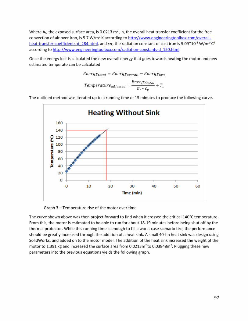
97
Where As, the exposed surface area, is 0.0213 m2 , h, the overall heat transfer coefficient for the free
convection of air over iron, is 5.7 W/m2 K according to http://www.engineeringtoolbox.com/overall-
heat-transfer-coefficients-d_284.html, and 𝜀𝜎, the radiation constant of cast iron is 5.09*10-8 W/m2°C4
according to http://www.engineeringtoolbox.com/radiation-constants-d_150.html.
Once the energy lost is calculated the new overall energy that goes towards heating the motor and new
estimated temperate can be calculated
𝐸𝑛𝑒𝑟𝑔𝑦𝑡𝑜𝑡𝑎𝑙 = 𝐸𝑛𝑒𝑟𝑔𝑦𝑜𝑣𝑒𝑟𝑎𝑙𝑙 − 𝐸𝑛𝑒𝑟𝑔𝑦𝑙𝑜𝑠𝑡
𝑇𝑒𝑚𝑝𝑒𝑟𝑎𝑡𝑢𝑟𝑒𝑎𝑑𝑗𝑢𝑠𝑡𝑒𝑑 =𝐸𝑛𝑒𝑟𝑔𝑦𝑡𝑜𝑡𝑎𝑙𝑚 ∗ 𝑐𝑝
+ 𝑇1
The outlined method was iterated up to a running time of 15 minutes to produce the following curve.
Graph 3 – Temperature rise of the motor over time
The curve shown above was then project forward to find when it crossed the critical 140°C temperature.
From this, the motor is estimated to be able to run for about 18-19 minutes before being shut off by the
thermal protector. While this running time is enough to fill a worst case scenario tire, the performance
should be greatly increased through the addition of a heat sink. A small 40-fin heat sink was design using
SolidWorks, and added on to the motor model. The addition of the heat sink increased the weight of the
motor to 1.391 kg and increased the surface area from 0.0213m2 to 0.03848m2. Plugging these new
parameters into the previous equations yields the following graph.

98
Graph 4 – Temperature rise in motor over time with heat sink
Again the curve was projected in order to find the estimated time to reach the shutoff point of 140°C.
The addition of the very small and simple heat sink increased the possible continuous operating time
from 18-19 minutes to 33-34 minutes.
Compressor Work
The work done by the compressor can be calculated using the equation
�̇�𝑐𝑜𝑚𝑝 = �̇�∆ℎ
In order to find the enthalpy, at point 2, the temperature at point 2 must be estimated using an
isentropic relation for an ideal gas assuming k=1.4.
𝑇2 = 𝑇1 (𝑃2𝑃1)
𝑘−1𝑘= 298 𝐾 ∗ (
120𝑝𝑠𝑖
14.7𝑝𝑠𝑖)
.41.4= 542.936𝐾
Using http://www.peacesoftware.de/einigewerte/luft_e.html to calculate the enthalpy of air at the
different temperatures and pressures result in
�̇�𝑐𝑜𝑚𝑝 = 0.000193444𝑘𝑔
𝑠∗ (298.5969 − 547.997)
𝑘𝐽
𝑘𝑔= 0.048
𝑘𝐽
𝑠
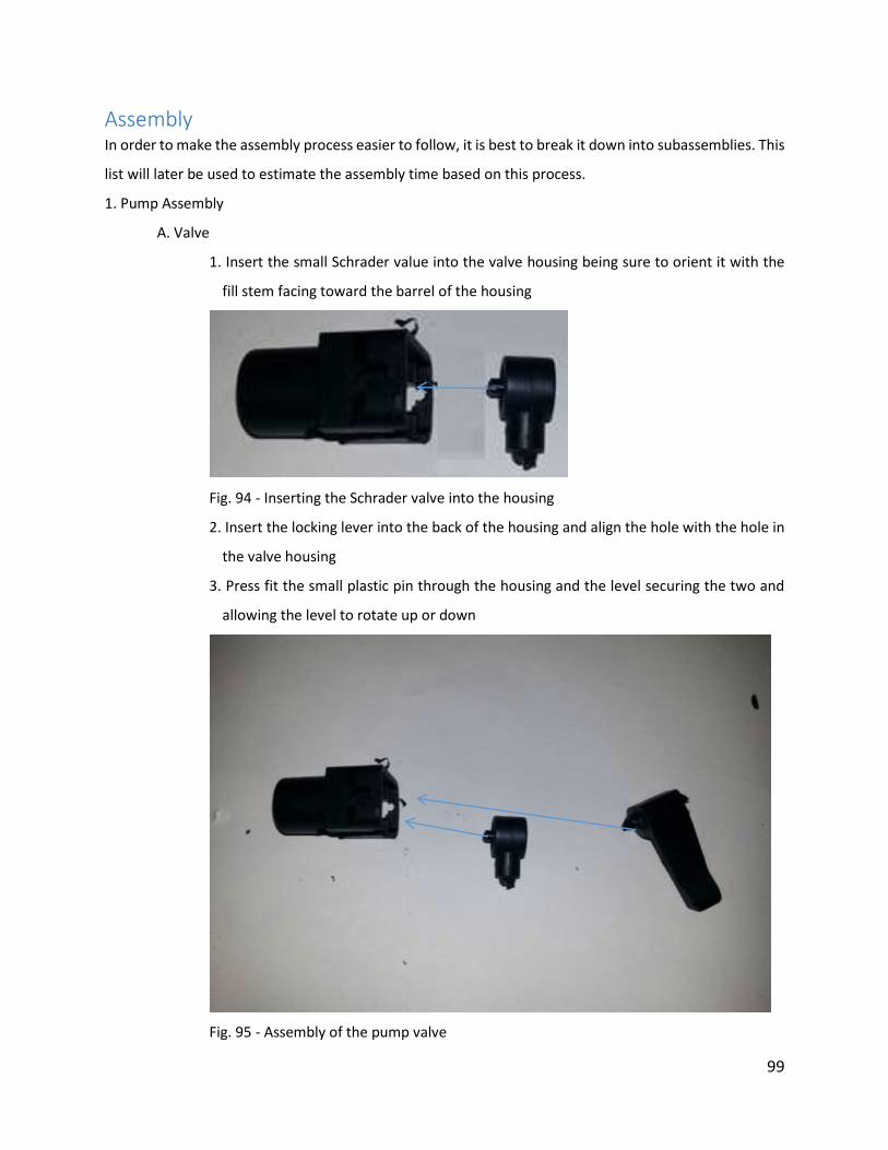
99
Assembly In order to make the assembly process easier to follow, it is best to break it down into subassemblies. This
list will later be used to estimate the assembly time based on this process.
1. Pump Assembly
A. Valve
1. Insert the small Schrader value into the valve housing being sure to orient it with the
fill stem facing toward the barrel of the housing
Fig. 94 - Inserting the Schrader valve into the housing
2. Insert the locking lever into the back of the housing and align the hole with the hole in
the valve housing
3. Press fit the small plastic pin through the housing and the level securing the two and
allowing the level to rotate up or down
Fig. 95 - Assembly of the pump valve

100
4. Slide the metal crown piece, flared edge down, over the top of one end of a rubber
hose
5. Insert the valve into the hose at the same end where the metal crown was placed
6. Crimp the metal crown to secure the hose to the valve while creating an air-tight seal
Fig. 96 - Attaching the valve to the hose
7. Slide a hose clamping spring onto the side of the hose opposite of the valve
7. Connect the hose from the compressor onto the left hose fitting for the pressure
vessel
6 Pressure vessel assembly
A) spring compartment assembly
1- pick up and align vessel

101
Fig. 97 – Vessel alignment
2- align gasket into spring compartment
Fig. 98 – Gasket alignment
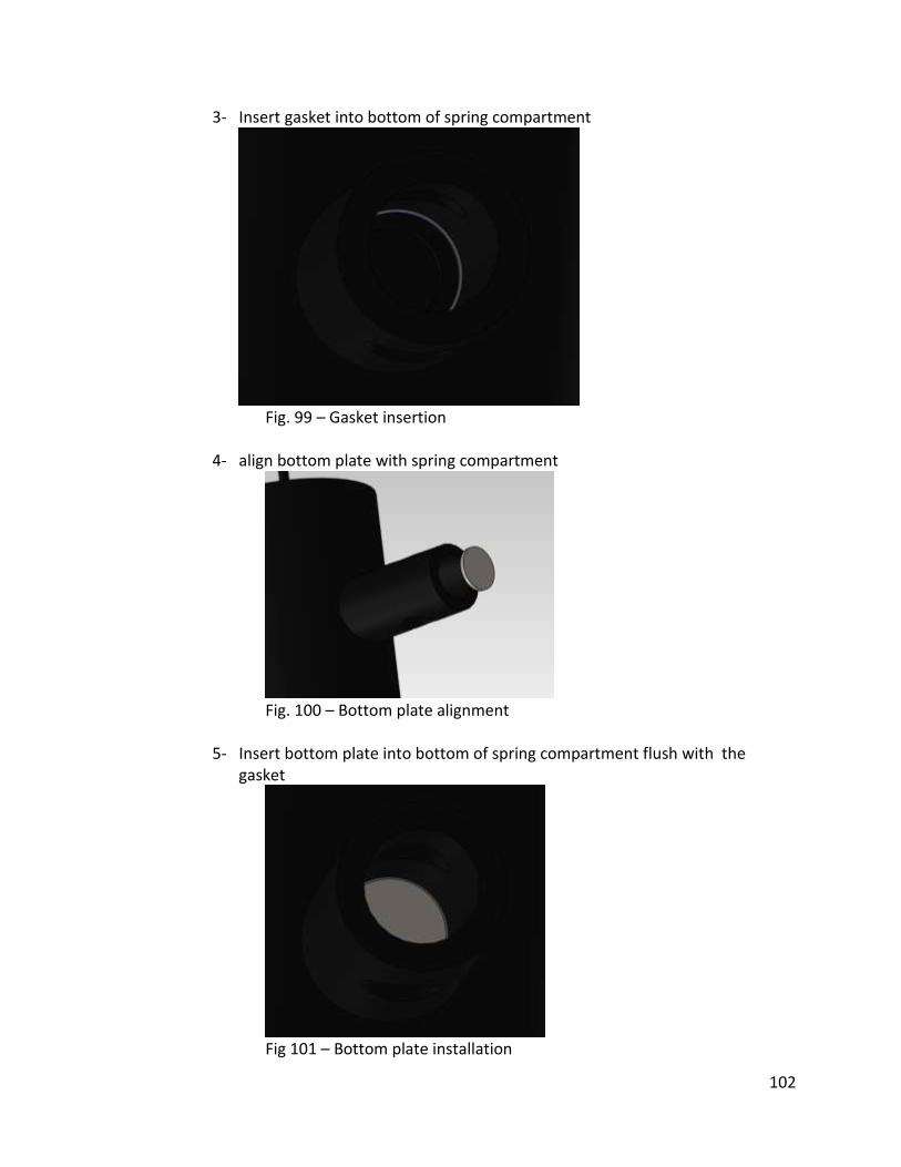
102
3- Insert gasket into bottom of spring compartment
Fig. 99 – Gasket insertion
4- align bottom plate with spring compartment
Fig. 100 – Bottom plate alignment
5- Insert bottom plate into bottom of spring compartment flush with the gasket
Fig 101 – Bottom plate installation
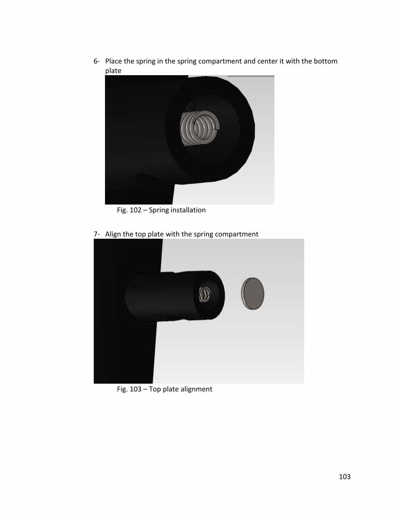
103
6- Place the spring in the spring compartment and center it with the bottom
plate
Fig. 102 – Spring installation
7- Align the top plate with the spring compartment
Fig. 103 – Top plate alignment
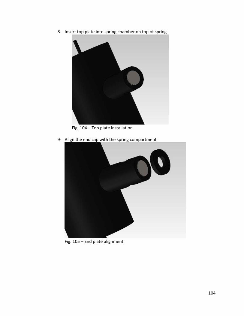
104
8- Insert top plate into spring chamber on top of spring
Fig. 104 – Top plate installation
9- Align the end cap with the spring compartment
Fig. 105 – End plate alignment
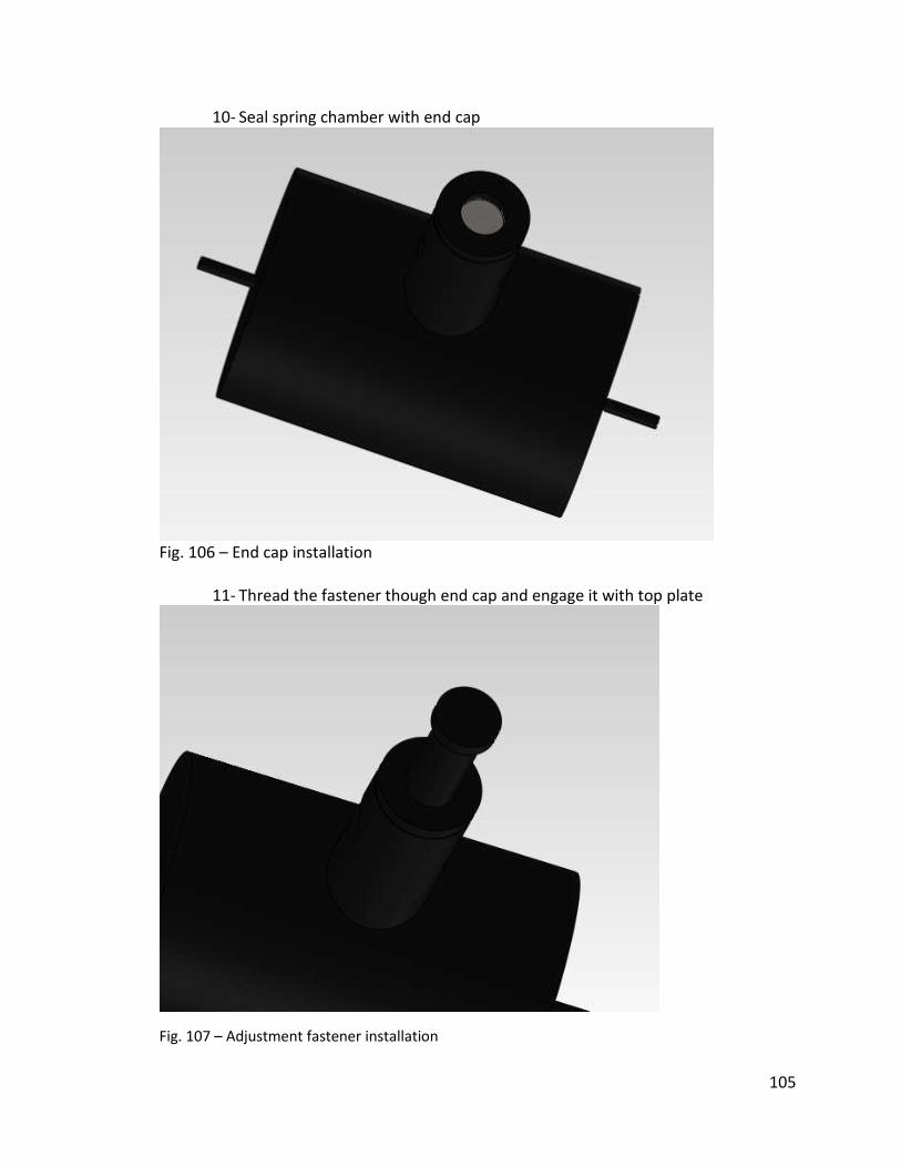
105
10- Seal spring chamber with end cap
Fig. 106 – End cap installation
11- Thread the fastener though end cap and engage it with top plate
Fig. 107 – Adjustment fastener installation
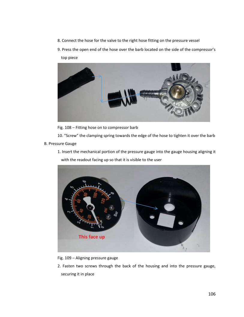
106
8. Connect the hose for the valve to the right hose fitting on the pressure vessel
9. Press the open end of the hose over the barb located on the side of the compressor’s
top piece
Fig. 108 – Fitting hose on to compressor barb
10. “Screw” the clamping spring towards the edge of the hose to tighten it over the barb
B. Pressure Gauge
1. Insert the mechanical portion of the pressure gauge into the gauge housing aligning it
with the readout facing up so that it is visible to the user
Fig. 109 – Aligning pressure gauge
2. Fasten two screws through the back of the housing and into the pressure gauge,
securing it in place

107
Fig. 110 - Preparing the pressure gauge assembly
3. Snap on the clear front plate onto the gauge housing
Fig. 111 - Assembled pressure gauge
4. Slide a clamping spring onto one end of a rubber hose
5. Press the same side of the hose over the gauge’s barb(brass fitting)
6. Tighten the spring to secure the hose to the barb
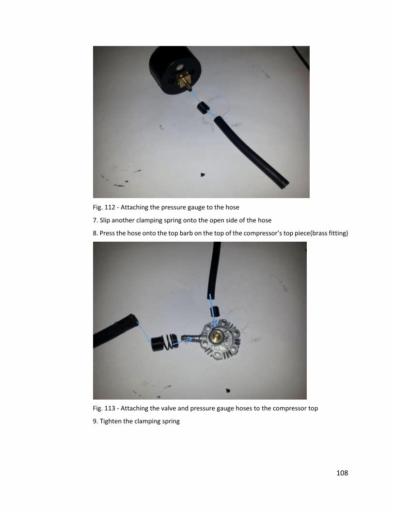
108
Fig. 112 - Attaching the pressure gauge to the hose
7. Slip another clamping spring onto the open side of the hose
8. Press the hose onto the top barb on the top of the compressor’s top piece(brass fitting)
Fig. 113 - Attaching the valve and pressure gauge hoses to the compressor top
9. Tighten the clamping spring
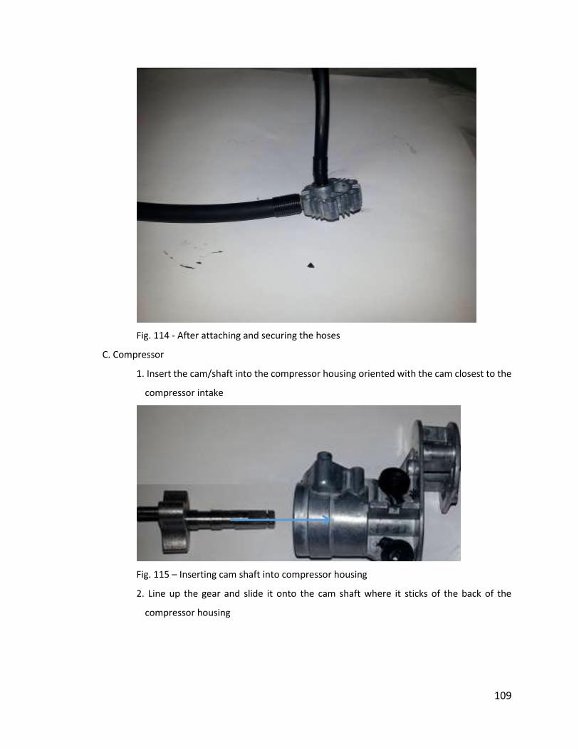
109
Fig. 114 - After attaching and securing the hoses
C. Compressor
1. Insert the cam/shaft into the compressor housing oriented with the cam closest to the
compressor intake
Fig. 115 – Inserting cam shaft into compressor housing
2. Line up the gear and slide it onto the cam shaft where it sticks of the back of the
compressor housing
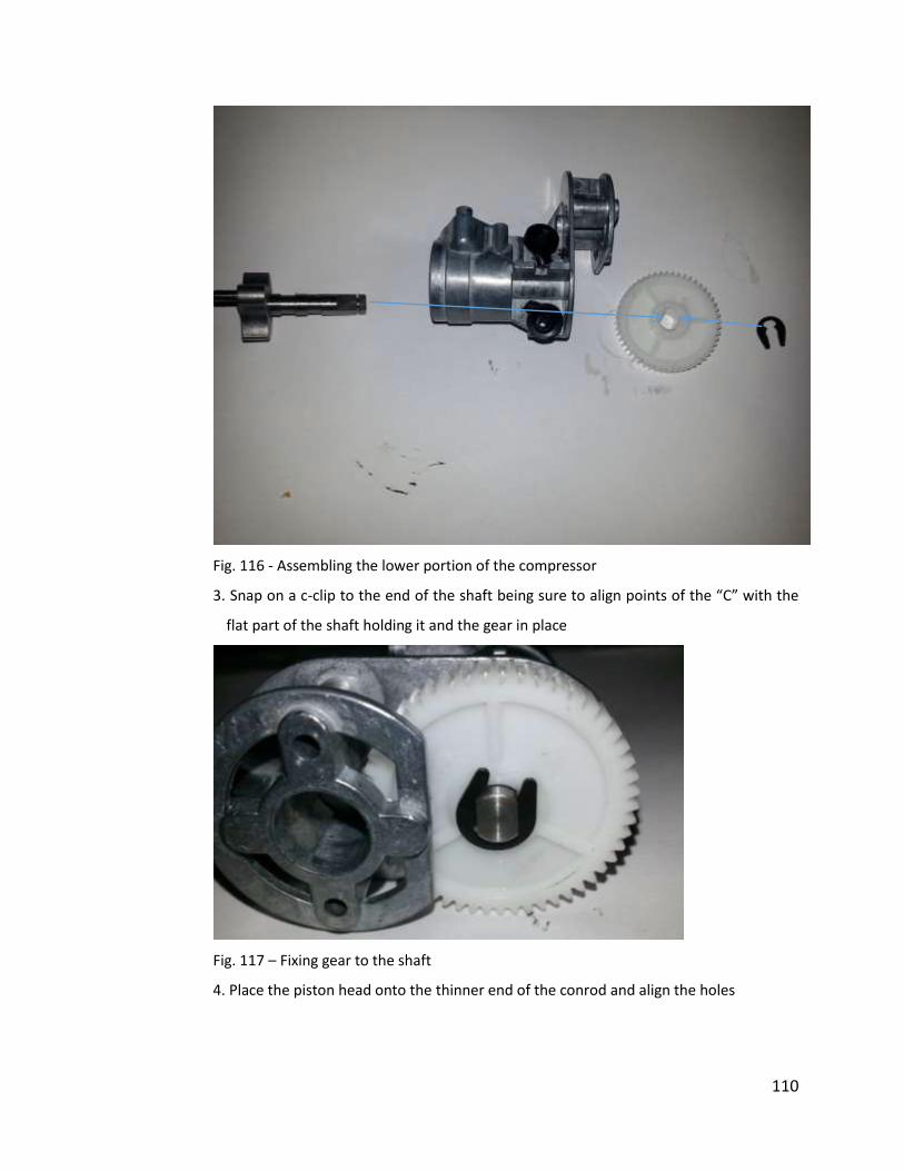
110
Fig. 116 - Assembling the lower portion of the compressor
3. Snap on a c-clip to the end of the shaft being sure to align points of the “C” with the
flat part of the shaft holding it and the gear in place
Fig. 117 – Fixing gear to the shaft
4. Place the piston head onto the thinner end of the conrod and align the holes
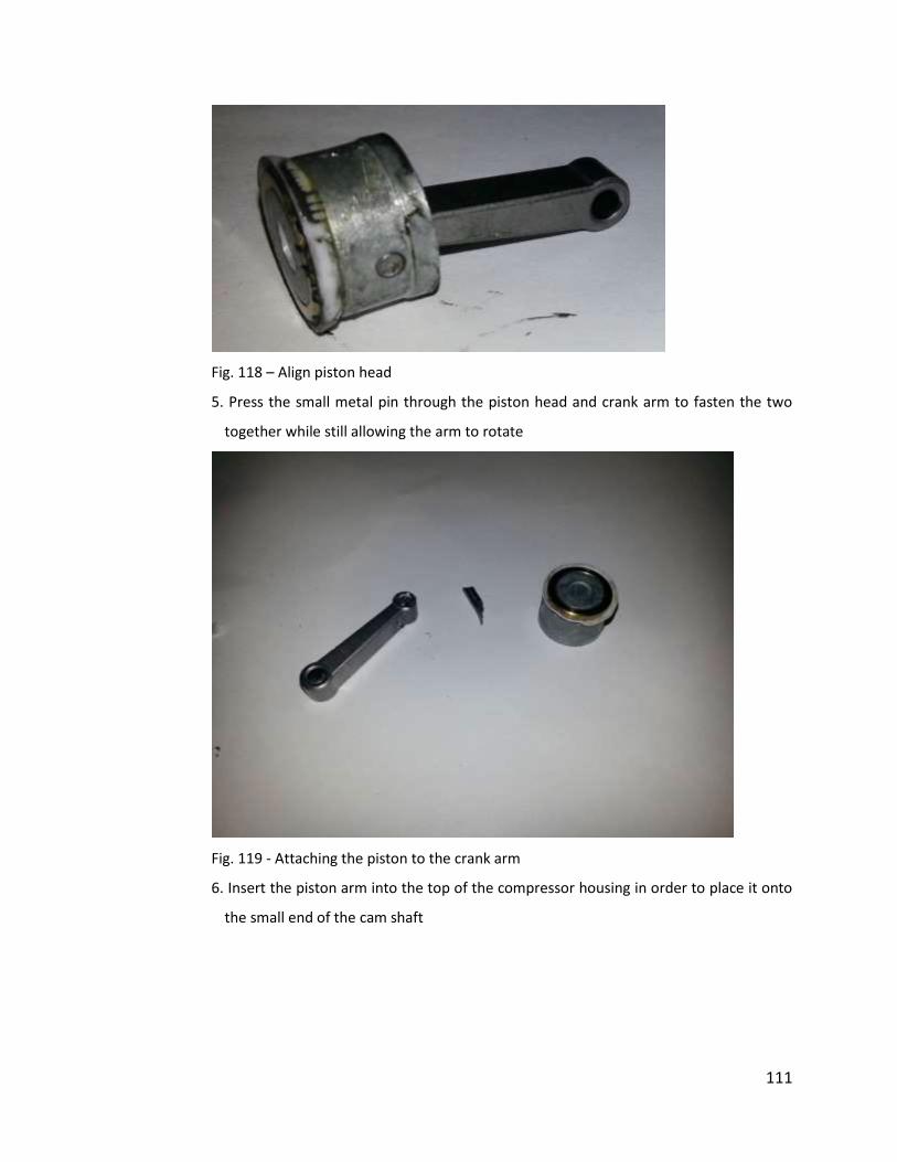
111
Fig. 118 – Align piston head
5. Press the small metal pin through the piston head and crank arm to fasten the two
together while still allowing the arm to rotate
Fig. 119 - Attaching the piston to the crank arm
6. Insert the piston arm into the top of the compressor housing in order to place it onto
the small end of the cam shaft
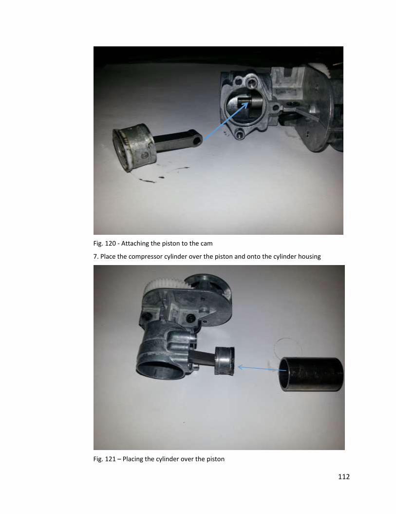
112
Fig. 120 - Attaching the piston to the cam
7. Place the compressor cylinder over the piston and onto the cylinder housing
Fig. 121 – Placing the cylinder over the piston

113
8. Place the compressor top piece with the attached pressure gauge and pump valve onto
the compressor cylinder
Fig. 122 - Attaching the top piece to the compressor
9. Fasten two screws through the top piece and into the housing in order to hold the
assembly together

114
Fig. 123 - Fully assembled compressor
10. Fasten two screws through the compressor housing into the motor ensuring that the
motor and compressor gears are in constant contact
Fig. 124 - Preparing to attach the motor
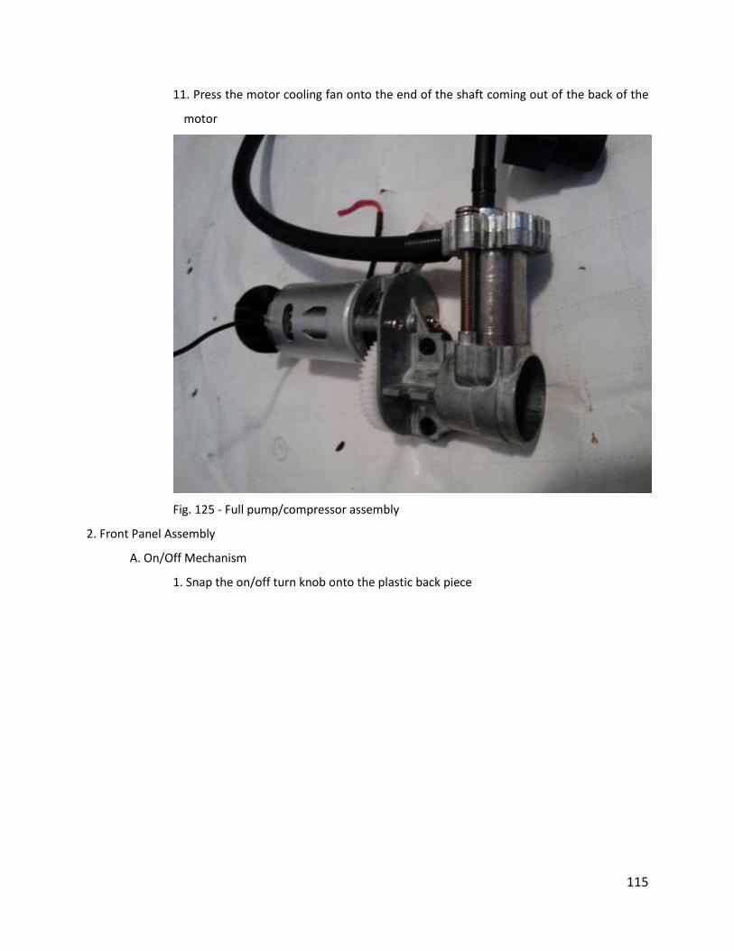
115
11. Press the motor cooling fan onto the end of the shaft coming out of the back of the
motor
Fig. 125 - Full pump/compressor assembly
2. Front Panel Assembly
A. On/Off Mechanism
1. Snap the on/off turn knob onto the plastic back piece

116
Fig. 126 - Attaching the on/off knob to the back piece
2. Insert the plastic back piece into the right most hole (from operator perspective) of the
front panel
Fig 127 – Inserting the switch into front panel
3. Fit the smaller of the two on/off body pieces to the back of the knob back piece
4. Insert the small jagged edged piece into the back of the body, flat side down that that
it sits flat in the cutout
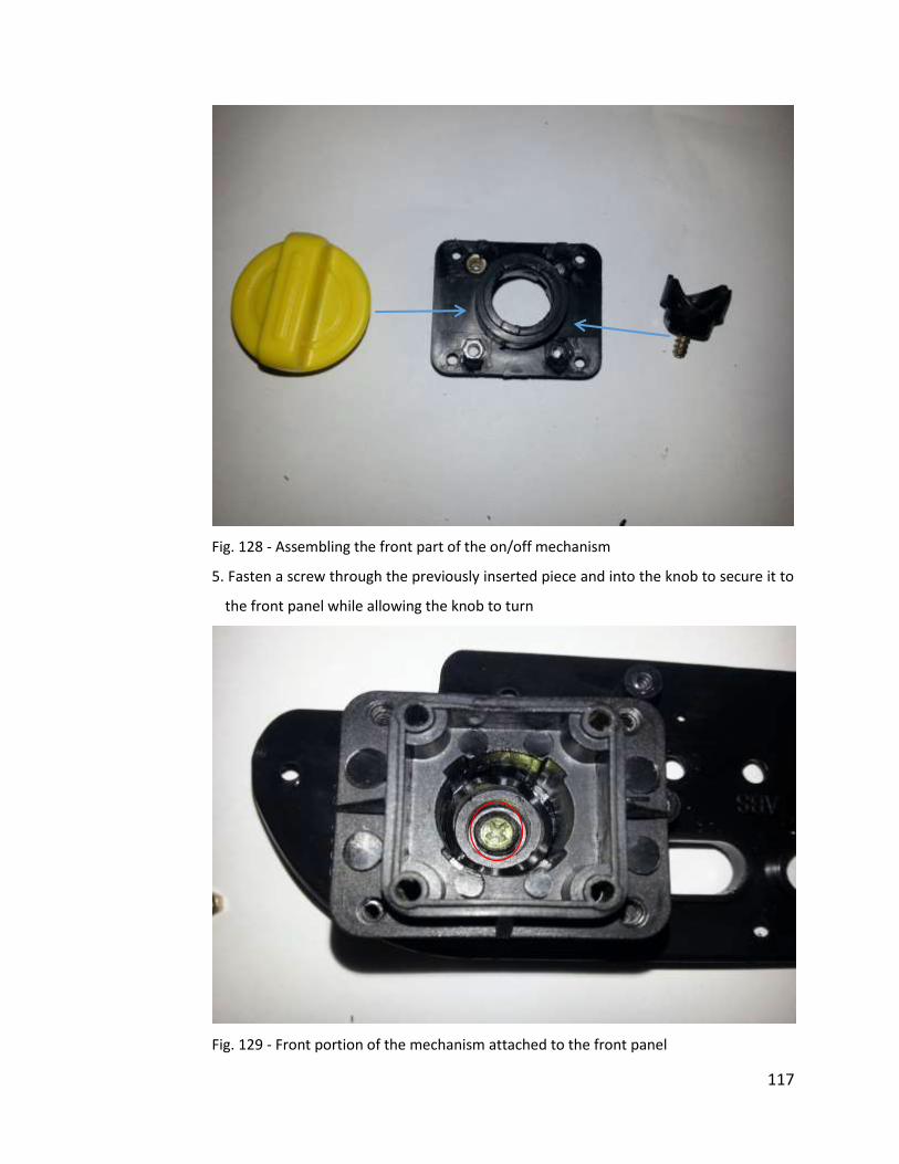
117
Fig. 128 - Assembling the front part of the on/off mechanism
5. Fasten a screw through the previously inserted piece and into the knob to secure it to
the front panel while allowing the knob to turn
Fig. 129 - Front portion of the mechanism attached to the front panel
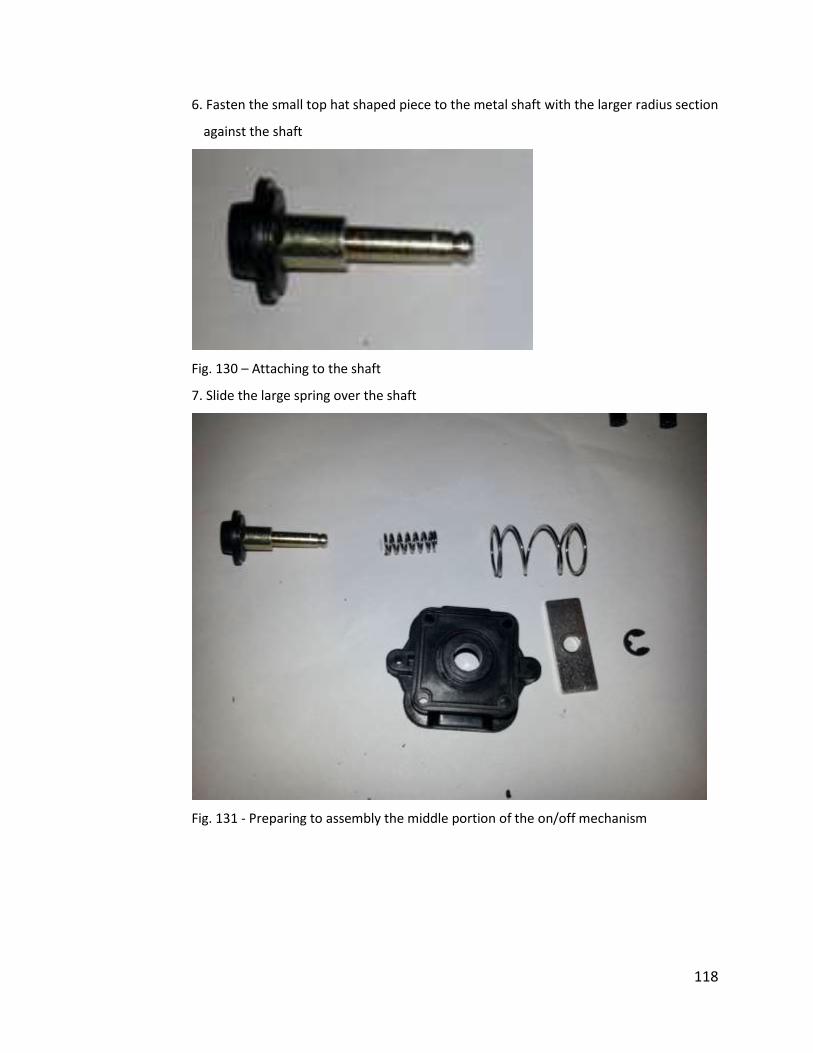
118
6. Fasten the small top hat shaped piece to the metal shaft with the larger radius section
against the shaft
Fig. 130 – Attaching to the shaft
7. Slide the large spring over the shaft
Fig. 131 - Preparing to assembly the middle portion of the on/off mechanism
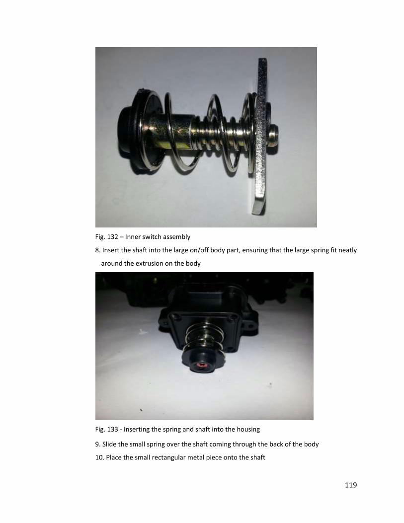
119
Fig. 132 – Inner switch assembly
8. Insert the shaft into the large on/off body part, ensuring that the large spring fit neatly
around the extrusion on the body
Fig. 133 - Inserting the spring and shaft into the housing
9. Slide the small spring over the shaft coming through the back of the body
10. Place the small rectangular metal piece onto the shaft
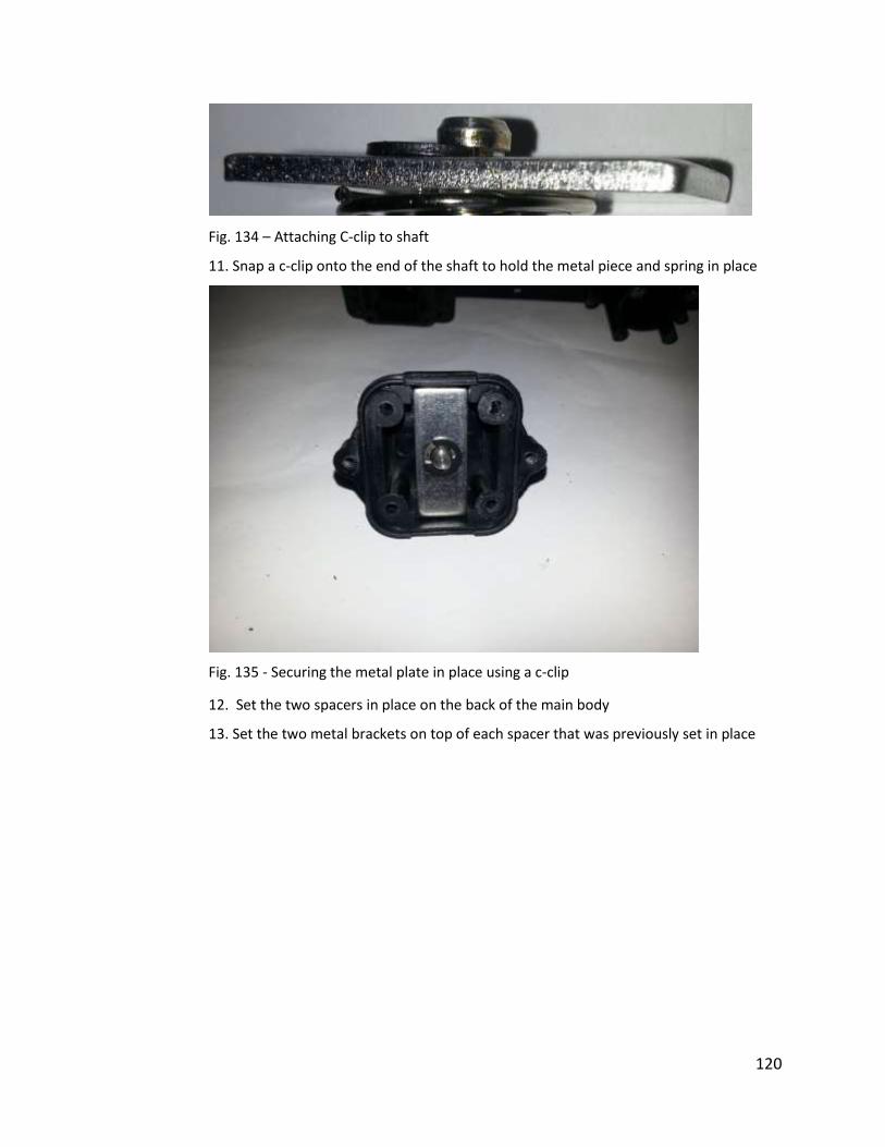
120
Fig. 134 – Attaching C-clip to shaft
11. Snap a c-clip onto the end of the shaft to hold the metal piece and spring in place
Fig. 135 - Securing the metal plate in place using a c-clip
12. Set the two spacers in place on the back of the main body
13. Set the two metal brackets on top of each spacer that was previously set in place
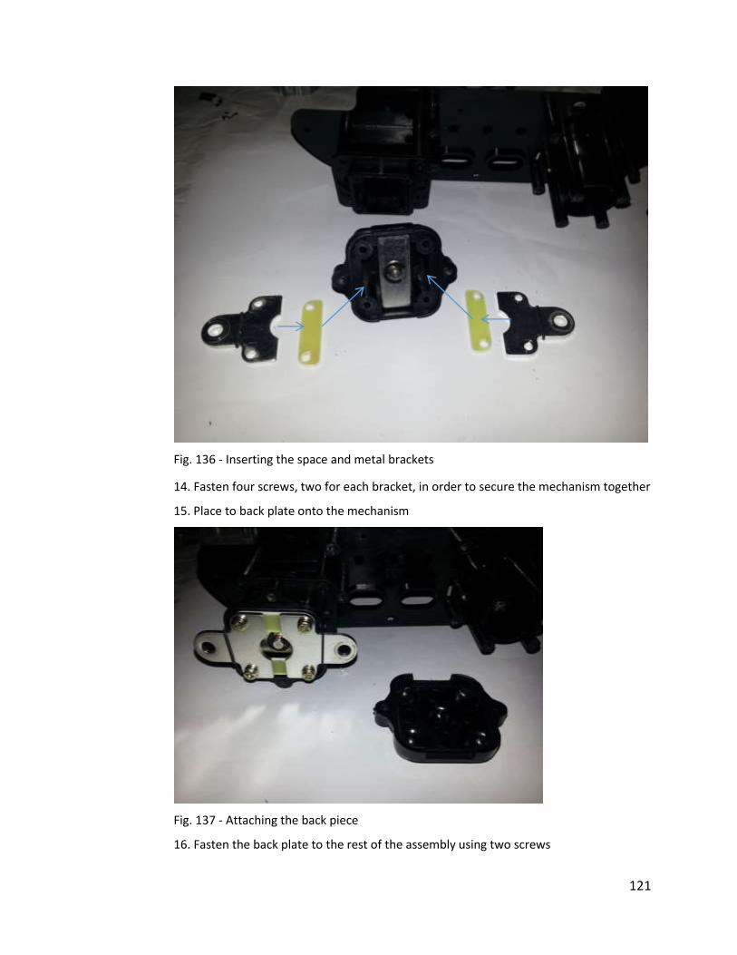
121
Fig. 136 - Inserting the space and metal brackets
14. Fasten four screws, two for each bracket, in order to secure the mechanism together
15. Place to back plate onto the mechanism
Fig. 137 - Attaching the back piece
16. Fasten the back plate to the rest of the assembly using two screws
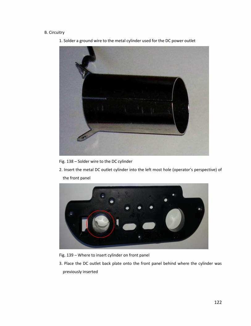
122
B. Circuitry
1. Solder a ground wire to the metal cylinder used for the DC power outlet
Fig. 138 – Solder wire to the DC cylinder
2. Insert the metal DC outlet cylinder into the left most hole (operator’s perspective) of
the front panel
Fig. 139 – Where to insert cylinder on front panel
3. Place the DC outlet back plate onto the front panel behind where the cylinder was
previously inserted
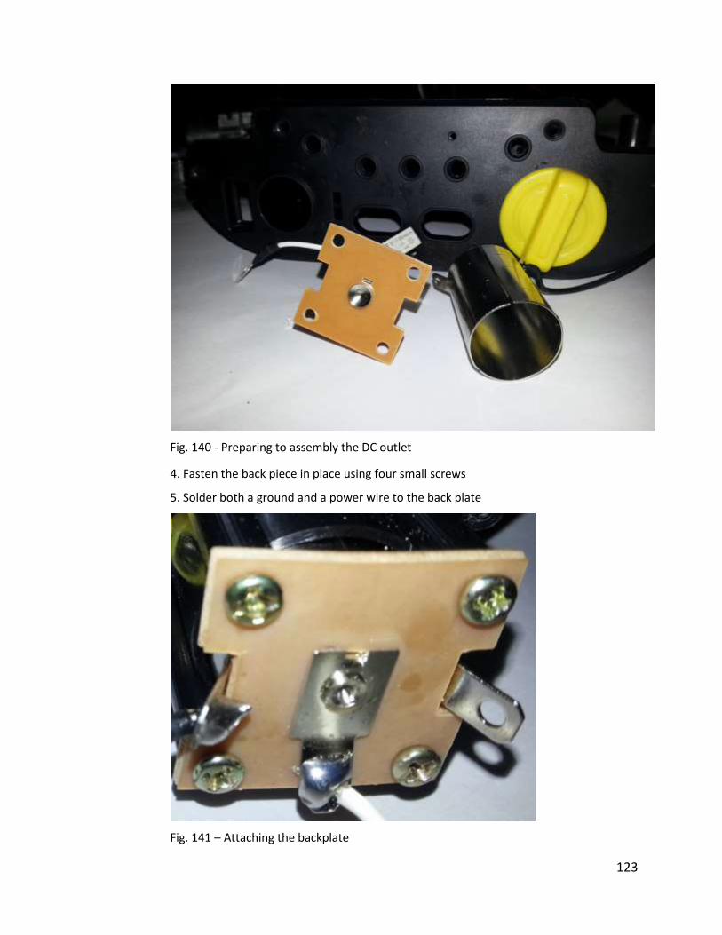
123
Fig. 140 - Preparing to assembly the DC outlet
4. Fasten the back piece in place using four small screws
5. Solder both a ground and a power wire to the back plate
Fig. 141 – Attaching the backplate
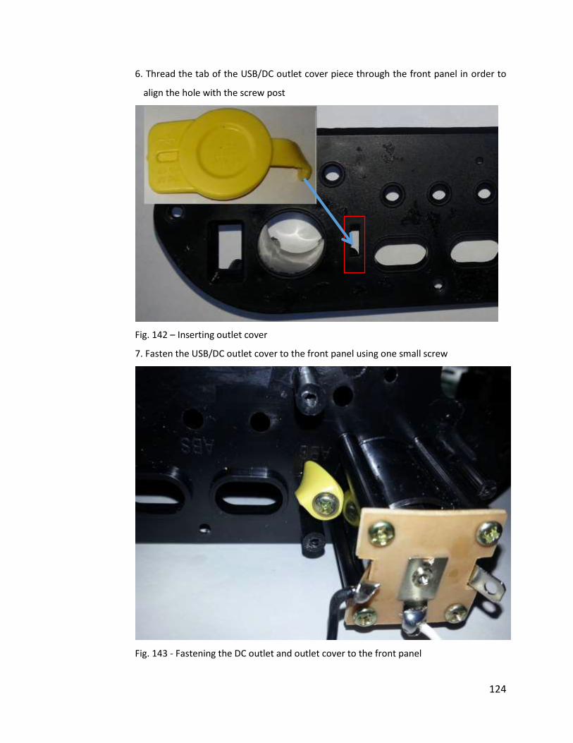
124
6. Thread the tab of the USB/DC outlet cover piece through the front panel in order to
align the hole with the screw post
Fig. 142 – Inserting outlet cover
7. Fasten the USB/DC outlet cover to the front panel using one small screw
Fig. 143 - Fastening the DC outlet and outlet cover to the front panel
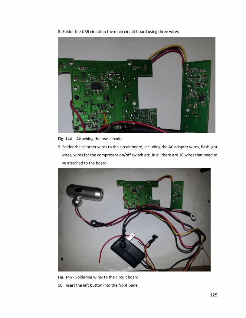
125
8. Solder the USB circuit to the main circuit board using three wires
Fig. 144 – Attaching the two circuits
9. Solder the all other wires to the circuit board, including the AC adapter wires, flashlight
wires, wires for the compressor on/off switch etc. In all there are 10 wires that need to
be attached to the board
Fig. 145 - Soldering wires to the circuit board
10. Insert the left button into the front panel
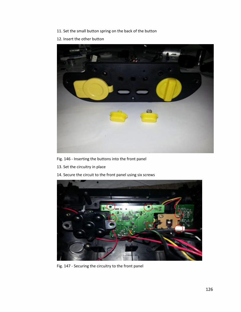
126
11. Set the small button spring on the back of the button
12. Insert the other button
Fig. 146 - Inserting the buttons into the front panel
13. Set the circuitry in place
14. Secure the circuit to the front panel using six screws
Fig. 147 - Securing the circuitry to the front panel
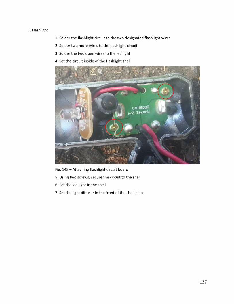
127
C. Flashlight
1. Solder the flashlight circuit to the two designated flashlight wires
2. Solder two more wires to the flashlight circuit
3. Solder the two open wires to the led light
4. Set the circuit inside of the flashlight shell
Fig. 148 – Attaching flashlight circuit board
5. Using two screws, secure the circuit to the shell
6. Set the led light in the shell
7. Set the light diffuser in the front of the shell piece
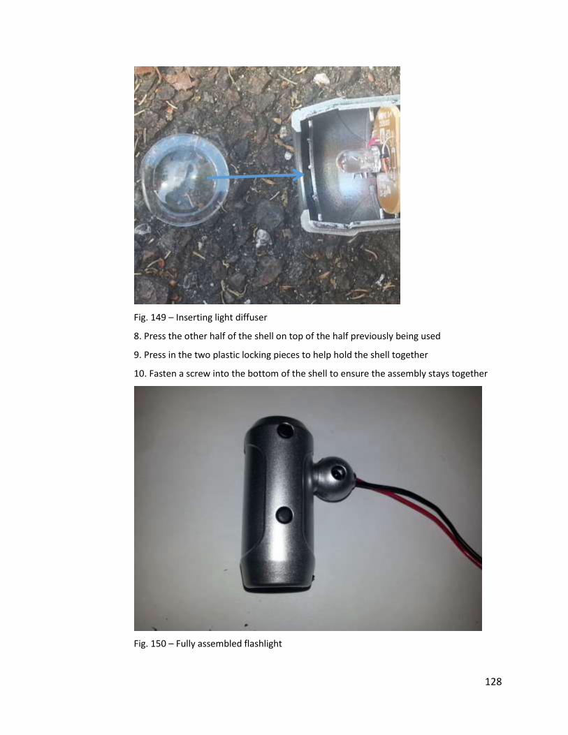
128
Fig. 149 – Inserting light diffuser
8. Press the other half of the shell on top of the half previously being used
9. Press in the two plastic locking pieces to help hold the shell together
10. Fasten a screw into the bottom of the shell to ensure the assembly stays together
Fig. 150 – Fully assembled flashlight

129
3. Inside Assembly
A. Main Housing
1. Attach the two front aesthetic panels to the front of the main housing
Fig. 151 – Attaching front panels
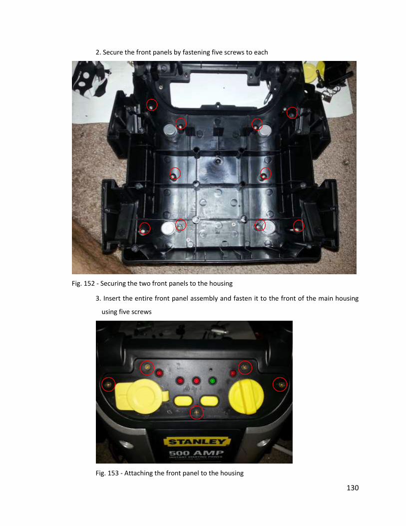
130
2. Secure the front panels by fastening five screws to each
Fig. 152 - Securing the two front panels to the housing
3. Insert the entire front panel assembly and fasten it to the front of the main housing
using five screws
Fig. 153 - Attaching the front panel to the housing

131
4. Insert a screw into the left bracket of the on/off mechanism (if looking at the back side
of the mechanism)
Fig. 154 - Preparing to attach the wires
5. Slide one power wire loop onto the screw
6. Slide one of the clamp cables onto the screw
7. Fasten a nut to the screw to ensure the two cables make a constant connection
8. Insert a screw into the right bracket of the on/off mechanism
9. Slide on the short main power cable
10. Fasten the cable into place using a nut
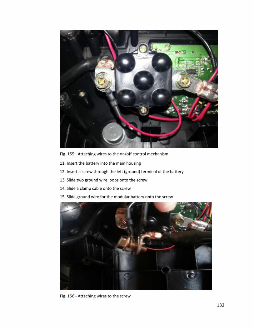
132
Fig. 155 - Attaching wires to the on/off control mechanism
11. Insert the battery into the main housing
12. Insert a screw through the left (ground) terminal of the battery
13. Slide two ground wire loops onto the screw
14. Slide a clamp cable onto the screw
15. Slide ground wire for the modular battery onto the screw
Fig. 156 - Attaching wires to the screw

133
16. Secure all the wires to the terminal by fastening a nut onto the screw
Fig. 157 - Attaching the wires to the ground terminal
17. Insert a screw into the right (hot) terminal of the battery
18. Slide on one hot wire loops
19. Slide on the short main power wire coming from the on/off mechanism
20. Slide the positive wire for the modular battery unit onto the bolt
Fig. 158 - Preparing to attach the hot wires
21. Secure the wire to the terminal using a nut
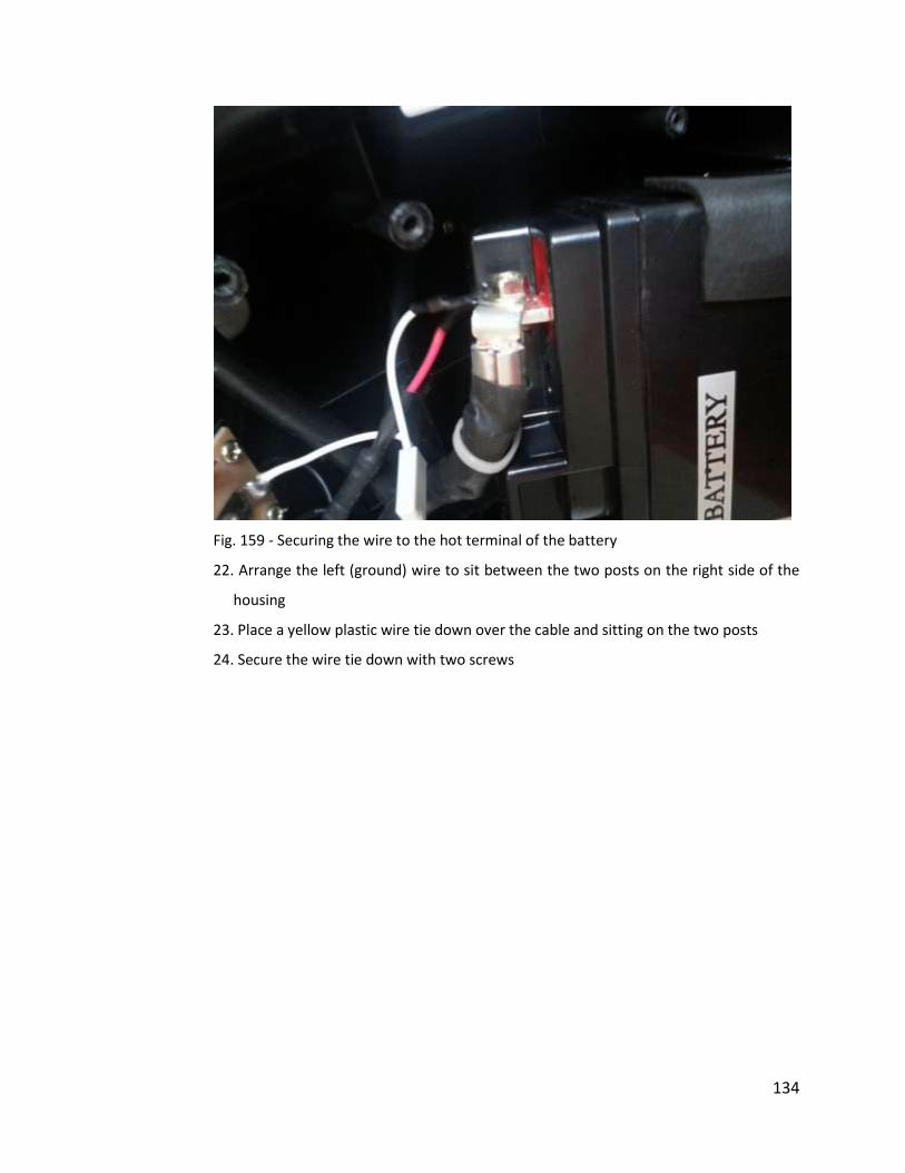
134
Fig. 159 - Securing the wire to the hot terminal of the battery
22. Arrange the left (ground) wire to sit between the two posts on the right side of the
housing
23. Place a yellow plastic wire tie down over the cable and sitting on the two posts
24. Secure the wire tie down with two screws
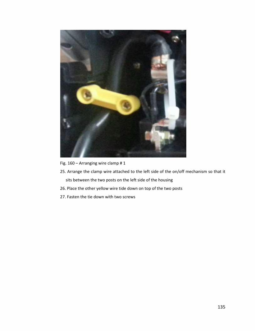
135
Fig. 160 – Arranging wire clamp # 1
25. Arrange the clamp wire attached to the left side of the on/off mechanism so that it
sits between the two posts on the left side of the housing
26. Place the other yellow wire tide down on top of the two posts
27. Fasten the tie down with two screws
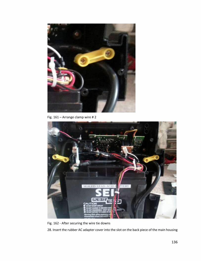
136
Fig. 161 – Arrange clamp wire # 2
Fig. 162 - After securing the wire tie downs
28. Insert the rubber AC adapter cover into the slot on the back piece of the main housing
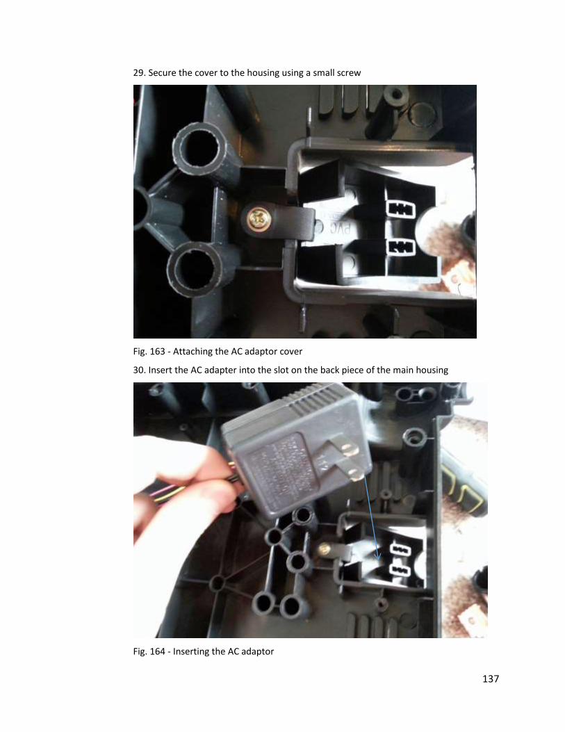
137
29. Secure the cover to the housing using a small screw
Fig. 163 - Attaching the AC adaptor cover
30. Insert the AC adapter into the slot on the back piece of the main housing
Fig. 164 - Inserting the AC adaptor
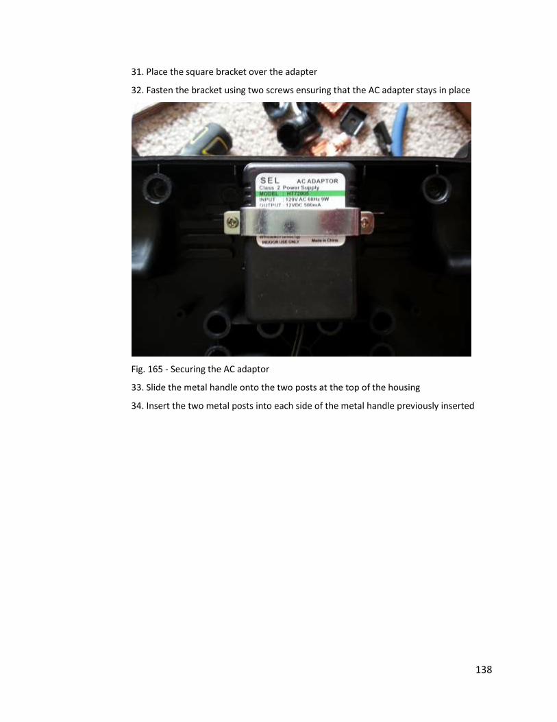
138
31. Place the square bracket over the adapter
32. Fasten the bracket using two screws ensuring that the AC adapter stays in place
Fig. 165 - Securing the AC adaptor
33. Slide the metal handle onto the two posts at the top of the housing
34. Insert the two metal posts into each side of the metal handle previously inserted
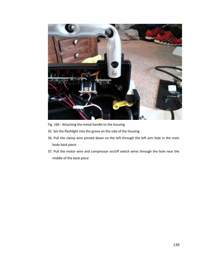
139
Fig. 166 - Attaching the metal handle to the housing
35. Set the flashlight into the grove on the side of the housing
36. Pull the clamp wire pinned down on the left through the left arm hole in the main
body back piece
37. Pull the motor wire and compressor on/off switch wires through the hole near the
middle of the back piece
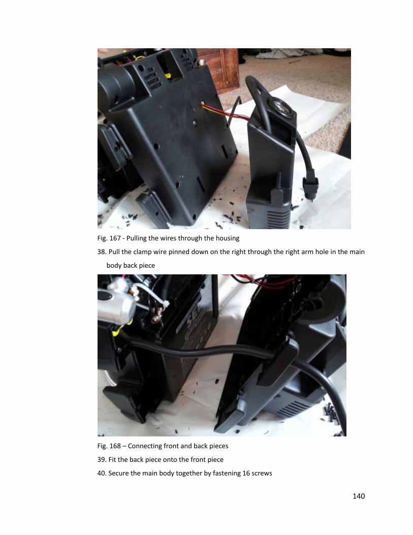
140
Fig. 167 - Pulling the wires through the housing
38. Pull the clamp wire pinned down on the right through the right arm hole in the main
body back piece
Fig. 168 – Connecting front and back pieces
39. Fit the back piece onto the front piece
40. Secure the main body together by fastening 16 screws
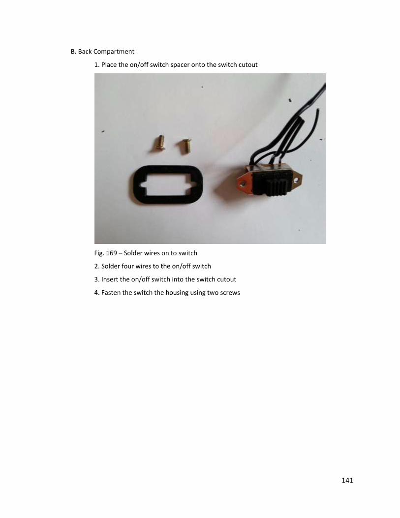
141
B. Back Compartment
1. Place the on/off switch spacer onto the switch cutout
Fig. 169 – Solder wires on to switch
2. Solder four wires to the on/off switch
3. Insert the on/off switch into the switch cutout
4. Fasten the switch the housing using two screws
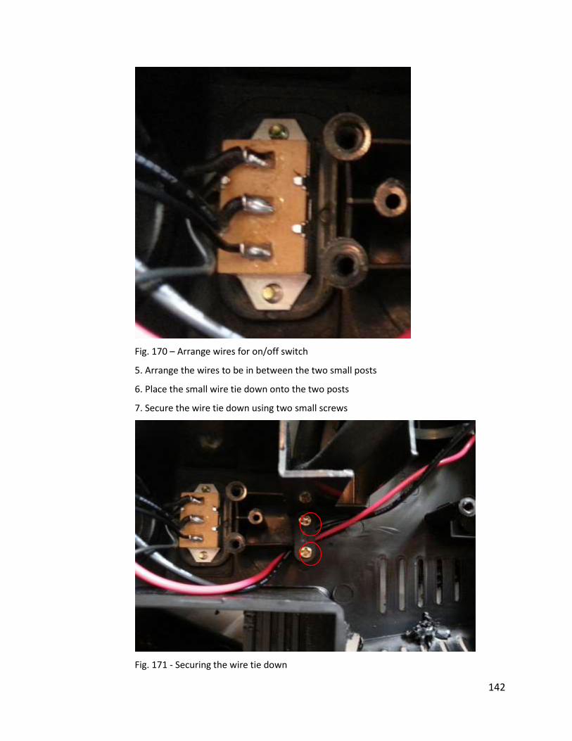
142
Fig. 170 – Arrange wires for on/off switch
5. Arrange the wires to be in between the two small posts
6. Place the small wire tie down onto the two posts
7. Secure the wire tie down using two small screws
Fig. 171 - Securing the wire tie down
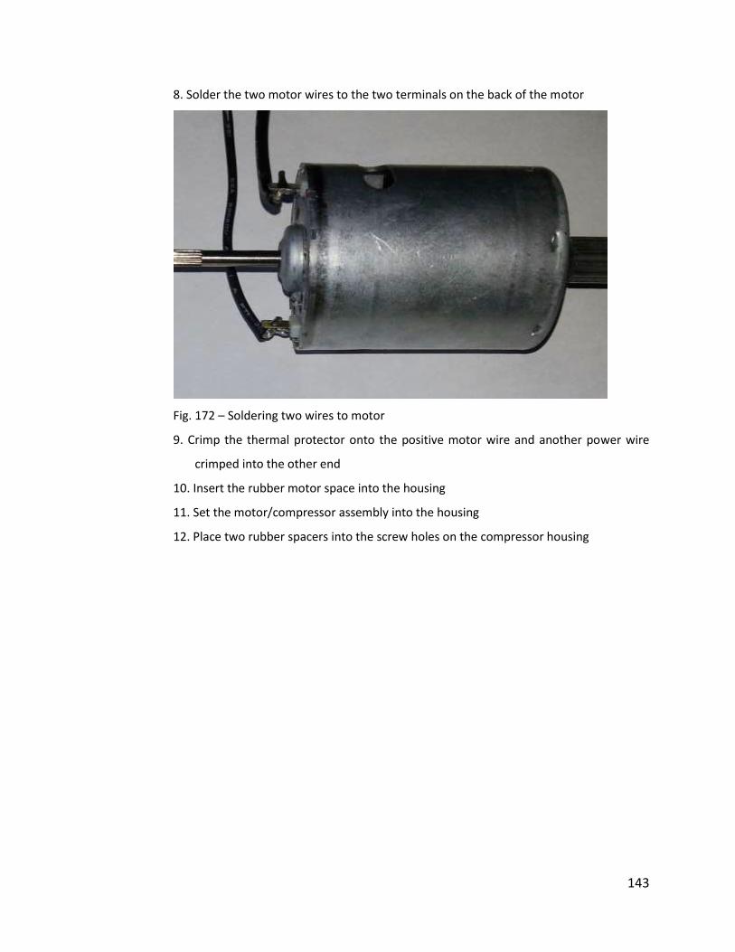
143
8. Solder the two motor wires to the two terminals on the back of the motor
Fig. 172 – Soldering two wires to motor
9. Crimp the thermal protector onto the positive motor wire and another power wire
crimped into the other end
10. Insert the rubber motor space into the housing
11. Set the motor/compressor assembly into the housing
12. Place two rubber spacers into the screw holes on the compressor housing
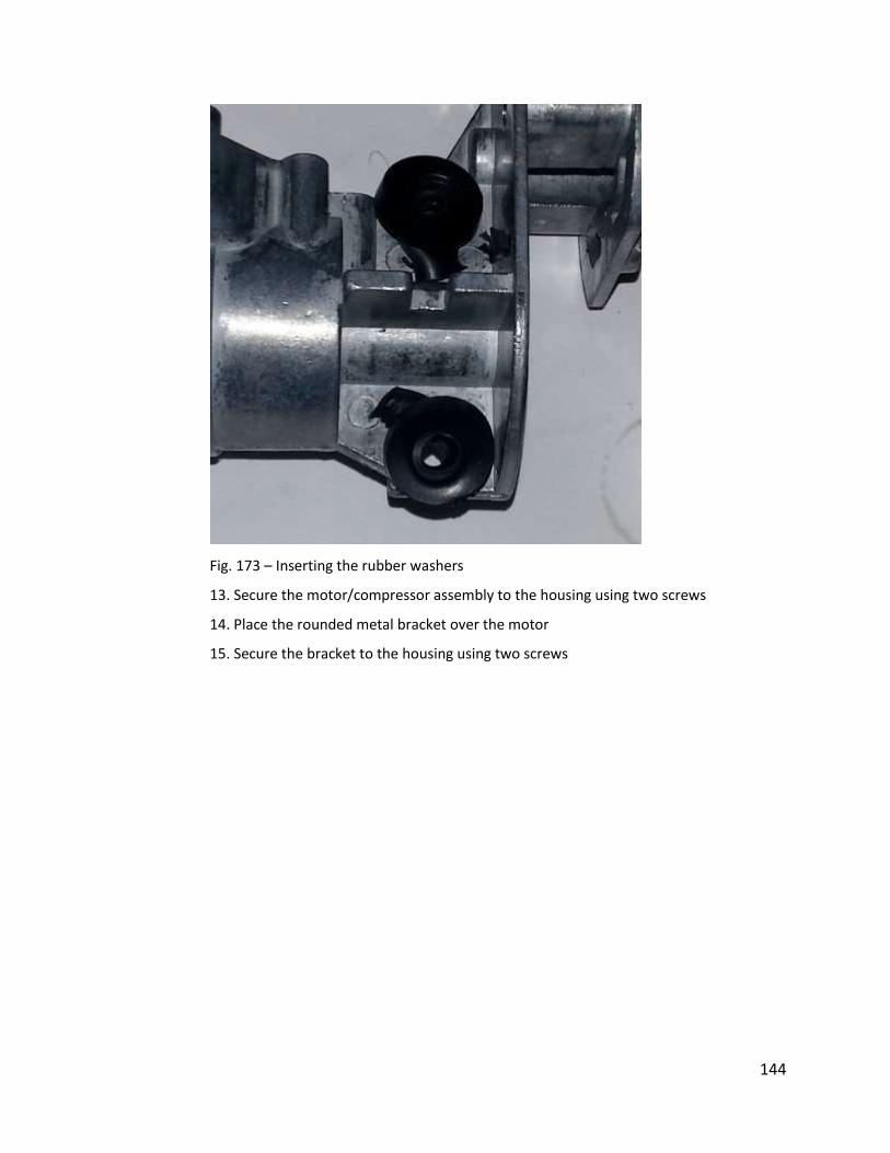
144
Fig. 173 – Inserting the rubber washers
13. Secure the motor/compressor assembly to the housing using two screws
14. Place the rounded metal bracket over the motor
15. Secure the bracket to the housing using two screws

145
Fig. 174 – Inserting the motor/compressor assembly into housing
16. Fit the pressure gauge assembly into the hole in the back of the housing
17. Place the angled metal bracket against the pressure gauge and on top of the two screw
posts
18. Fasten the bracket to the housing using two screws

146
Fig. 175 - Attaching the bracket to hold the pressure gauge in place
19. Pull the pump valve through the square hole in the top of the housing
20. Place the back housing compartment onto the main housing
21. Fasten the two bodies together using six screws
4. External Components
A. Body
1. Insert a plastic corner bumper into the metal handle
2. Insert the other half of the bumper into the handle
3. Secure the two halves around the handle using one screw
4. Repeat steps 1, 2, and 3 for the bumper on the other side of the handle
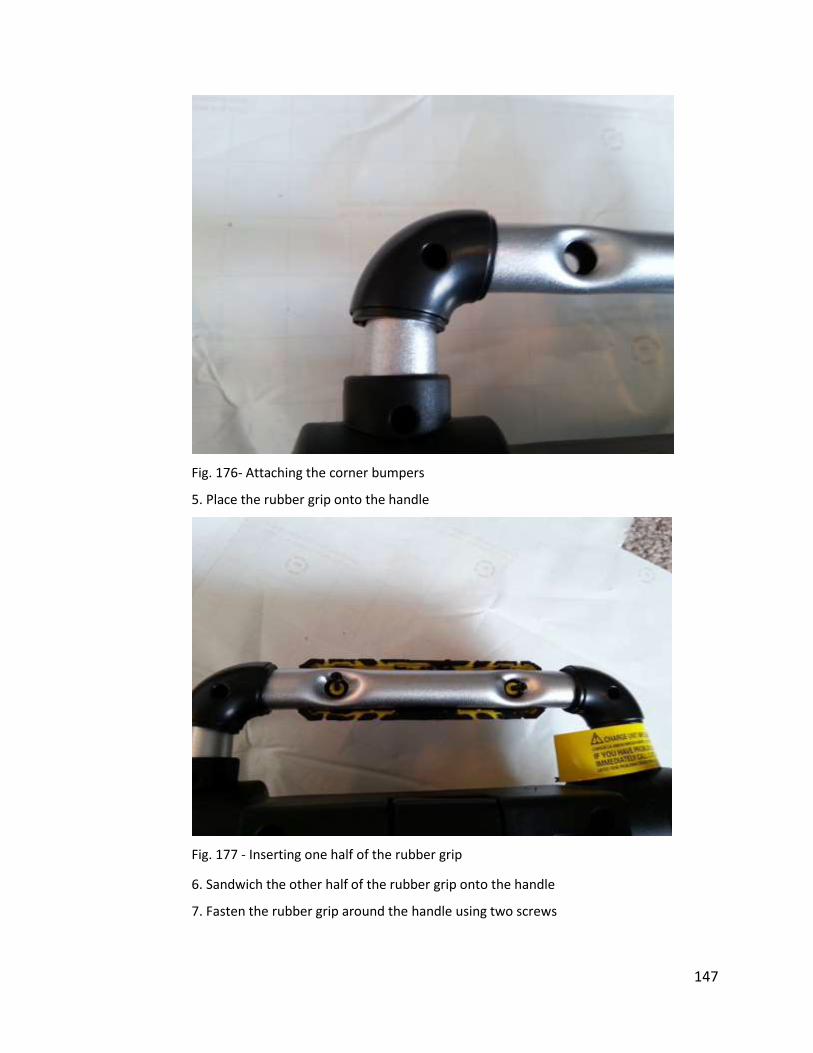
147
Fig. 176- Attaching the corner bumpers
5. Place the rubber grip onto the handle
Fig. 177 - Inserting one half of the rubber grip
6. Sandwich the other half of the rubber grip onto the handle
7. Fasten the rubber grip around the handle using two screws
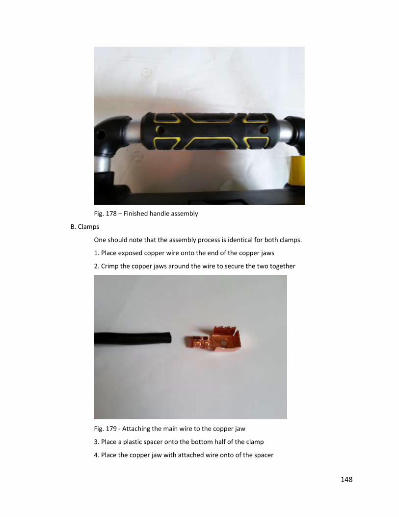
148
Fig. 178 – Finished handle assembly
B. Clamps
One should note that the assembly process is identical for both clamps.
1. Place exposed copper wire onto the end of the copper jaws
2. Crimp the copper jaws around the wire to secure the two together
Fig. 179 - Attaching the main wire to the copper jaw
3. Place a plastic spacer onto the bottom half of the clamp
4. Place the copper jaw with attached wire onto of the spacer
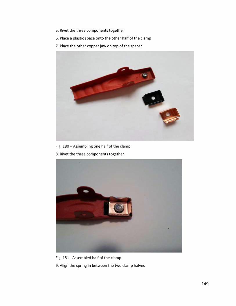
149
5. Rivet the three components together
6. Place a plastic space onto the other half of the clamp
7. Place the other copper jaw on top of the spacer
Fig. 180 – Assembling one half of the clamp
8. Rivet the three components together
Fig. 181 - Assembled half of the clamp
9. Align the spring in between the two clamp halves
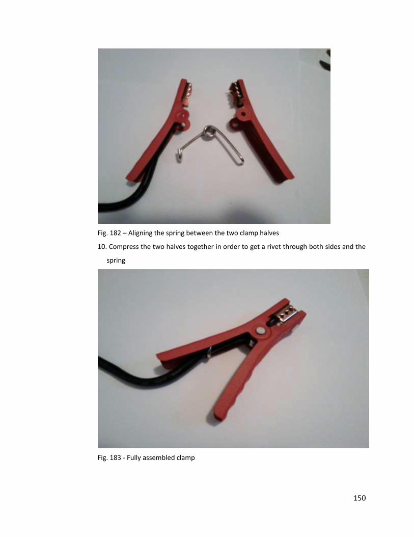
150
Fig. 182 – Aligning the spring between the two clamp halves
10. Compress the two halves together in order to get a rivet through both sides and the
spring
Fig. 183 - Fully assembled clamp
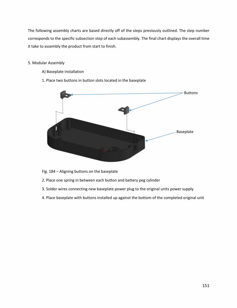
151
The following assembly charts are based directly off of the steps previously outlined. The step number
corresponds to the specific subsection step of each subassembly. The final chart displays the overall time
it take to assembly the product from start to finish.
5. Modular Assembly
A) Baseplate installation
1. Place two buttons in button slots located in the baseplate
Fig. 184 – Aligning buttons on the baseplate
2. Place one spring in between each button and battery peg cylinder
3. Solder wires connecting new baseplate power plug to the original units power supply
4. Place baseplate with buttons installed up against the bottom of the completed original unit
Baseplate
Buttons
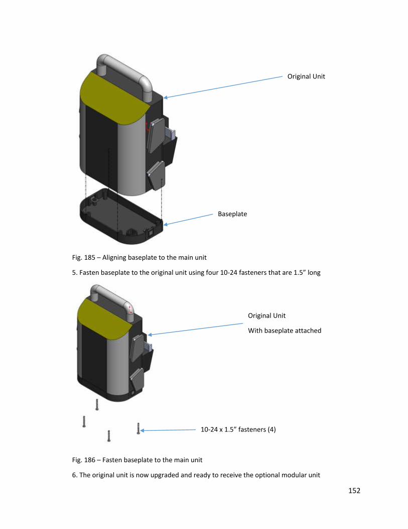
152
Fig. 185 – Aligning baseplate to the main unit
5. Fasten baseplate to the original unit using four 10-24 fasteners that are 1.5” long
Fig. 186 – Fasten baseplate to the main unit
6. The original unit is now upgraded and ready to receive the optional modular unit
Baseplate
Original Unit
10-24 x 1.5” fasteners (4)
Original Unit
With baseplate attached
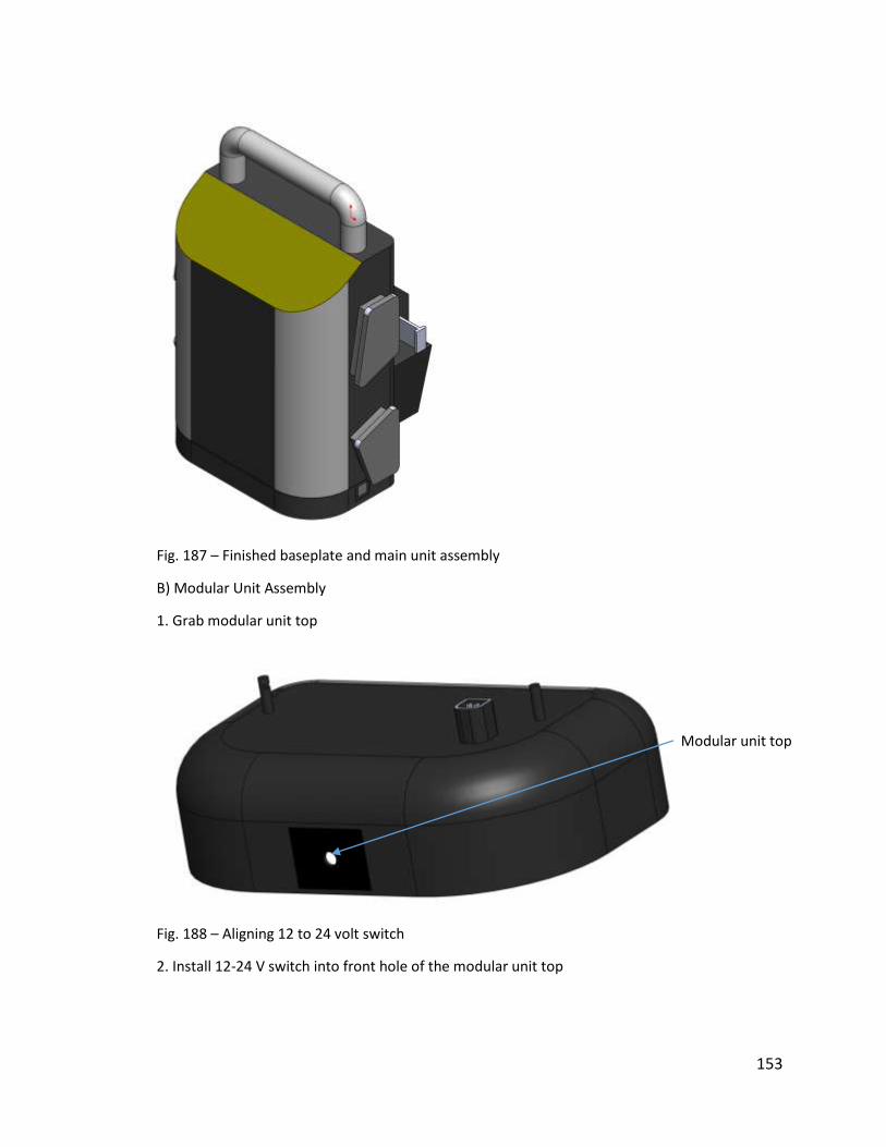
153
Fig. 187 – Finished baseplate and main unit assembly
B) Modular Unit Assembly
1. Grab modular unit top
Fig. 188 – Aligning 12 to 24 volt switch
2. Install 12-24 V switch into front hole of the modular unit top
Modular unit top
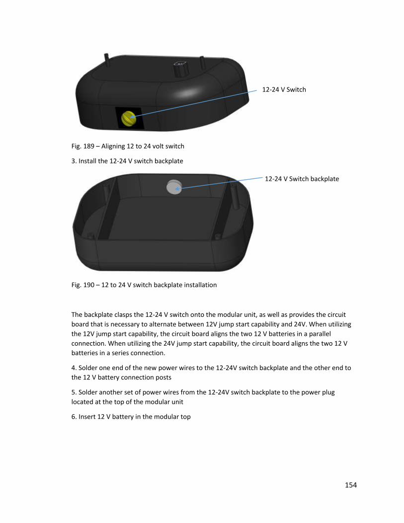
154
Fig. 189 – Aligning 12 to 24 volt switch
3. Install the 12-24 V switch backplate
Fig. 190 – 12 to 24 V switch backplate installation
The backplate clasps the 12-24 V switch onto the modular unit, as well as provides the circuit
board that is necessary to alternate between 12V jump start capability and 24V. When utilizing
the 12V jump start capability, the circuit board aligns the two 12 V batteries in a parallel
connection. When utilizing the 24V jump start capability, the circuit board aligns the two 12 V
batteries in a series connection.
4. Solder one end of the new power wires to the 12-24V switch backplate and the other end to
the 12 V battery connection posts
5. Solder another set of power wires from the 12-24V switch backplate to the power plug
located at the top of the modular unit
6. Insert 12 V battery in the modular top
12-24 V Switch backplate
12-24 V Switch

155
Fig. 191 – 12 V battery installation
7. Position modular unit bottom over the bottom side of the 12 V battery
Fig. 192 – Aligning the modular unit bottom
Modular unit top
12 V Lead-acid battery
Modular unit bottom
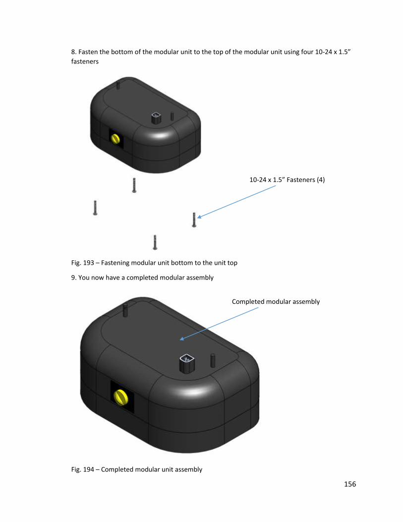
156
8. Fasten the bottom of the modular unit to the top of the modular unit using four 10-24 x 1.5”
fasteners
Fig. 193 – Fastening modular unit bottom to the unit top
9. You now have a completed modular assembly
Fig. 194 – Completed modular unit assembly
10-24 x 1.5” Fasteners (4)
Completed modular assembly

157
Cost Analysis In order to determine the cost of this device multiple sources of cost were taken into account. The
three major categories of cost were material cost, manufacturing cost, and assembly cost.
Material Cost – To determine the raw material cost of the device the amount of material necessary to
produce each part was determined. The mass of each part had to be found. Each part used from the
original device was massed with a scale. Any parts that were custom created had their masses
approximated using Solidworks. Material cost in grams per US dollars were found from various retailers
on the internet. Using these costs along with the mass of the material necessary for each part the cost
to purchase the raw materials could be found. Below is a sample calculation.
First the mass of the material is found, along with its bulk material cost
Mass of pressure vessel = 417.3 grams
Unit cost of ABS = $0.0025 per gram
Using these two values the raw material cost of the pressure vessel can be found as shown below
𝑅𝑎𝑤 𝑚𝑎𝑡𝑒𝑟𝑎𝑙 𝑐𝑜𝑠𝑡 = 417.3 𝑔𝑟𝑎𝑚𝑠 ∗0.0025 𝑑𝑜𝑙𝑙𝑎𝑟𝑠
1 𝑔𝑟𝑎𝑚 𝐴𝐵𝑆= $1.04
This was then computed for each part of the device. The material costs for each part can be seen in the
table below.
Modular Unit Materials
Part Name Material Unit Cost/Unit Amount Cost
Modular Top ABS grams $0.0025 848.2 $2.1205
Modular Bottom ABS grams $0.0025 421.8 $1.0545
12-24V Switch ABS grams $0.0025 4.5 $0.0113
Switch Backplate ABS grams $0.0025 4.5 $0.0113
Circuit Board N/A each $3.0000 1 $3.0000
10-24 x 1.5" Phillips Head Pan Screws
Stainless Steel
each 8 $0.0000
Wiring N/A in $0.0050 12 $0.0600
Power Plug N/A each $0.0600 1 $0.0600
12 V Battery N/A each $11.7500 1 $11.7500
Total
Material Cost
$18.0675
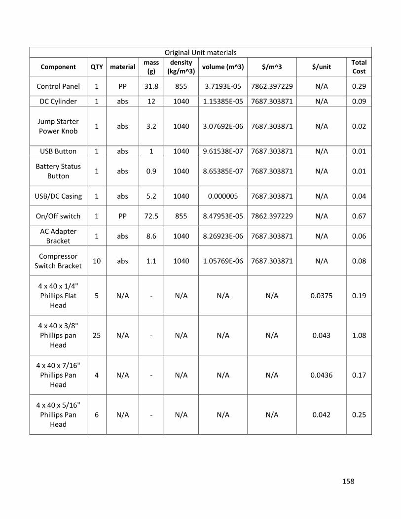
158
Original Unit materials
Component QTY material mass
(g) density
(kg/m^3) volume (m^3) $/m^3 $/unit
Total Cost
Control Panel 1 PP 31.8 855 3.7193E-05 7862.397229 N/A 0.29
DC Cylinder 1 abs 12 1040 1.15385E-05 7687.303871 N/A 0.09
Jump Starter Power Knob
1 abs 3.2 1040 3.07692E-06 7687.303871 N/A 0.02
USB Button 1 abs 1 1040 9.61538E-07 7687.303871 N/A 0.01
Battery Status Button
1 abs 0.9 1040 8.65385E-07 7687.303871 N/A 0.01
USB/DC Casing 1 abs 5.2 1040 0.000005 7687.303871 N/A 0.04
On/Off switch 1 PP 72.5 855 8.47953E-05 7862.397229 N/A 0.67
AC Adapter Bracket
1 abs 8.6 1040 8.26923E-06 7687.303871 N/A 0.06
Compressor Switch Bracket
10 abs 1.1 1040 1.05769E-06 7687.303871 N/A 0.08
4 x 40 x 1/4" Phillips Flat
Head 5 N/A - N/A N/A N/A 0.0375 0.19
4 x 40 x 3/8" Phillips pan
Head 25 N/A - N/A N/A N/A 0.043 1.08
4 x 40 x 7/16" Phillips Pan
Head 4 N/A - N/A N/A N/A 0.0436 0.17
4 x 40 x 5/16" Phillips Pan
Head 6 N/A - N/A N/A N/A 0.042 0.25
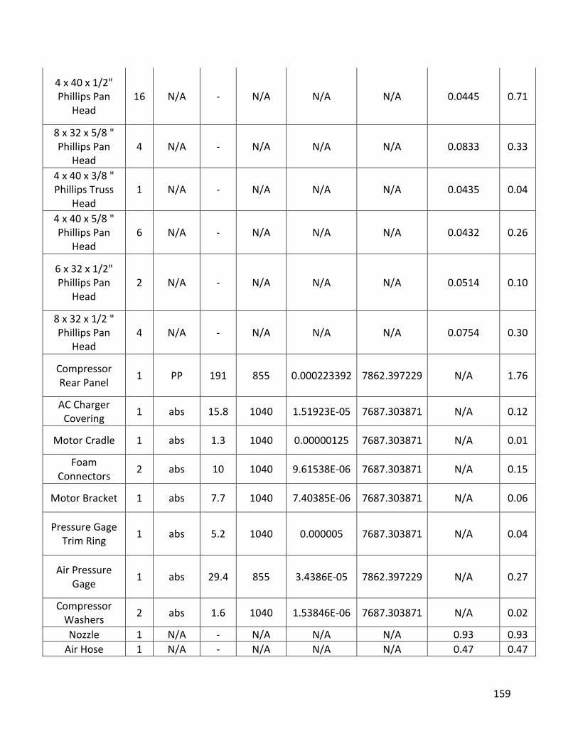
159
4 x 40 x 1/2" Phillips Pan
Head 16 N/A - N/A N/A N/A 0.0445 0.71
8 x 32 x 5/8 " Phillips Pan
Head 4 N/A - N/A N/A N/A 0.0833 0.33
4 x 40 x 3/8 " Phillips Truss
Head 1 N/A - N/A N/A N/A 0.0435 0.04
4 x 40 x 5/8 " Phillips Pan
Head 6 N/A - N/A N/A N/A 0.0432 0.26
6 x 32 x 1/2" Phillips Pan
Head 2 N/A - N/A N/A N/A 0.0514 0.10
8 x 32 x 1/2 " Phillips Pan
Head 4 N/A - N/A N/A N/A 0.0754 0.30
Compressor Rear Panel
1 PP 191 855 0.000223392 7862.397229 N/A 1.76
AC Charger Covering
1 abs 15.8 1040 1.51923E-05 7687.303871 N/A 0.12
Motor Cradle 1 abs 1.3 1040 0.00000125 7687.303871 N/A 0.01
Foam Connectors
2 abs 10 1040 9.61538E-06 7687.303871 N/A 0.15
Motor Bracket 1 abs 7.7 1040 7.40385E-06 7687.303871 N/A 0.06
Pressure Gage Trim Ring
1 abs 5.2 1040 0.000005 7687.303871 N/A 0.04
Air Pressure Gage
1 abs 29.4 855 3.4386E-05 7862.397229 N/A 0.27
Compressor Washers
2 abs 1.6 1040 1.53846E-06 7687.303871 N/A 0.02
Nozzle 1 N/A - N/A N/A N/A 0.93 0.93
Air Hose 1 N/A - N/A N/A N/A 0.47 0.47
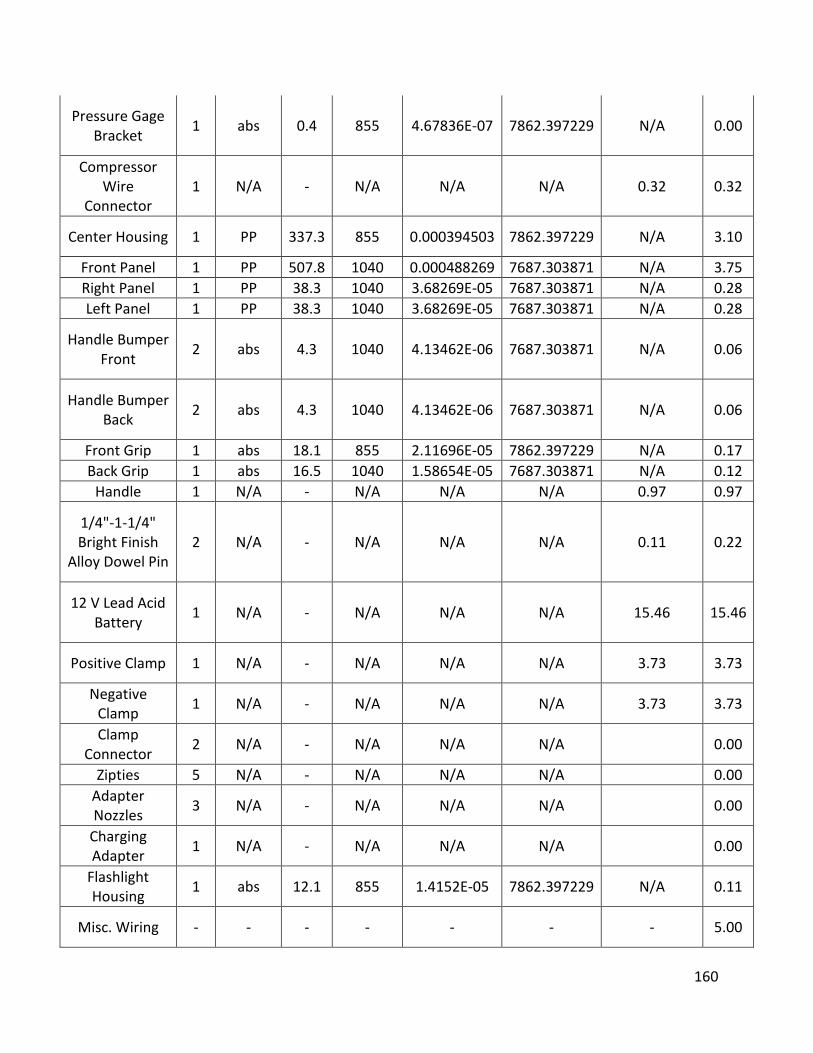
160
Pressure Gage Bracket
1 abs 0.4 855 4.67836E-07 7862.397229 N/A 0.00
Compressor Wire
Connector 1 N/A - N/A N/A N/A 0.32 0.32
Center Housing 1 PP 337.3 855 0.000394503 7862.397229 N/A 3.10
Front Panel 1 PP 507.8 1040 0.000488269 7687.303871 N/A 3.75
Right Panel 1 PP 38.3 1040 3.68269E-05 7687.303871 N/A 0.28
Left Panel 1 PP 38.3 1040 3.68269E-05 7687.303871 N/A 0.28
Handle Bumper Front
2 abs 4.3 1040 4.13462E-06 7687.303871 N/A 0.06
Handle Bumper Back
2 abs 4.3 1040 4.13462E-06 7687.303871 N/A 0.06
Front Grip 1 abs 18.1 855 2.11696E-05 7862.397229 N/A 0.17
Back Grip 1 abs 16.5 1040 1.58654E-05 7687.303871 N/A 0.12
Handle 1 N/A - N/A N/A N/A 0.97 0.97
1/4"-1-1/4" Bright Finish
Alloy Dowel Pin 2 N/A - N/A N/A N/A 0.11 0.22
12 V Lead Acid Battery
1 N/A - N/A N/A N/A 15.46 15.46
Positive Clamp 1 N/A - N/A N/A N/A 3.73 3.73
Negative Clamp
1 N/A - N/A N/A N/A 3.73 3.73
Clamp Connector
2 N/A - N/A N/A N/A 0.00
Zipties 5 N/A - N/A N/A N/A 0.00
Adapter Nozzles
3 N/A - N/A N/A N/A 0.00
Charging Adapter
1 N/A - N/A N/A N/A 0.00
Flashlight Housing
1 abs 12.1 855 1.4152E-05 7862.397229 N/A 0.11
Misc. Wiring - - - - - - - 5.00

161
Misc. Circuit Boards
- - - - - - - 7.00
60 ZY DC Motor 1 N/A N/A N/A N/A N/A 20 20.00
Total
Material Cost 72.91
Pressure Vessel Materials
Part Material Unit Cost/Unit Amount Cost
Vessel ABS Grams 0.0025 417.3 1.04325
End Cap ABS Grams 0.0025 4.53 0.011325
Gasket N/A Each 0.04 1 0.04
Top Plate Stainless Steel grams 0.0007 9.07 0.006349
Bottom Plate Stainless Steel Grams 0.0007 9.07 0.006349
Adjustment Fastener
ABS Grams 0.0025 18.14 0.04535
Spring N/A Each 1.38 1 1.38
Electrical contact N/A each 0.1 1 0.1
Total Material
Cost 2.632623
Charts 2 through 4 – Total material costs for each subassembly
Assembly Cost- To estimate the assembly cost the assembly procedure had to be used. Using the
handling and insertion time charts times for each step could be estimated. Based on the size and grip of
the parts being assembled a time for each step was selected. Once a time was selected it was then
multiplied by the wage to employ a US worker. This was done for each assembly step to find the total
cost to assemble the entire device.
Below is an example of an estimate to assemble part of the pressure regulator. It is for assembling the
bottom plate into the pressure regulator. First the two angles of orientation were determined to
properly orient the plate with the pressure vessel. Alpha was determined to be 180 degrees. This
means the plate can be oriented properly every time it is rotated 180 degrees about the alpha axis. The
beta angle is 0 degrees. This means no matter what the orientation about the beta axis it will be
oriented correctly. This is because it is a disk and has symmetry about the beta axis. To find the time
the chart is then used with the angles. The size of the part must be taken into account. The sum of
alpha and beta is less than 360 so the value will be in row 0. The part has a thickness greater than 2 mm
so it will be in either column 1, 2, or 3. The size is greater than 15 millimeter therefore the time to
perform this action is 1.13 seconds. Next, the time to insert the plate into the chamber is found. For this
time the insertion chart must be used. This analysis is not as objective as the handling time. The first
row was selected because the part can be considered easy to reach and no tools are required. The first
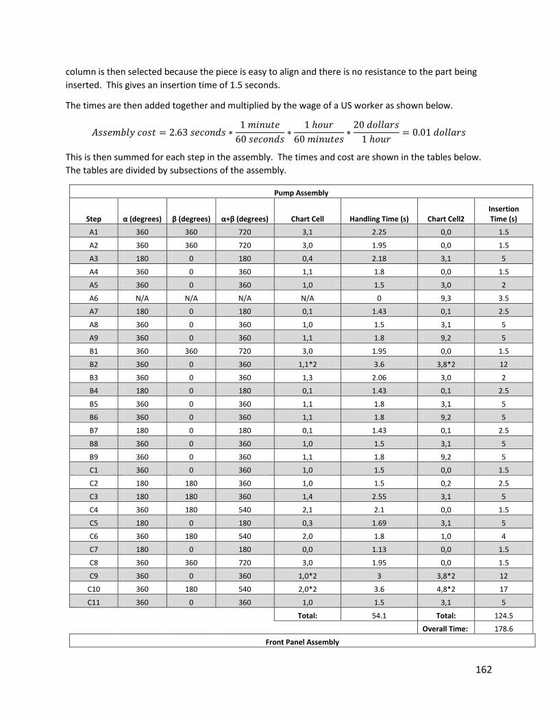
162
column is then selected because the piece is easy to align and there is no resistance to the part being
inserted. This gives an insertion time of 1.5 seconds.
The times are then added together and multiplied by the wage of a US worker as shown below.
𝐴𝑠𝑠𝑒𝑚𝑏𝑙𝑦 𝑐𝑜𝑠𝑡 = 2.63 𝑠𝑒𝑐𝑜𝑛𝑑𝑠 ∗1 𝑚𝑖𝑛𝑢𝑡𝑒
60 𝑠𝑒𝑐𝑜𝑛𝑑𝑠∗
1 ℎ𝑜𝑢𝑟
60 𝑚𝑖𝑛𝑢𝑡𝑒𝑠∗20 𝑑𝑜𝑙𝑙𝑎𝑟𝑠
1 ℎ𝑜𝑢𝑟= 0.01 𝑑𝑜𝑙𝑙𝑎𝑟𝑠
This is then summed for each step in the assembly. The times and cost are shown in the tables below.
The tables are divided by subsections of the assembly.
Pump Assembly
Step α (degrees) β (degrees) α+β (degrees) Chart Cell Handling Time (s) Chart Cell2 Insertion Time (s)
A1 360 360 720 3,1 2.25 0,0 1.5
A2 360 360 720 3,0 1.95 0,0 1.5
A3 180 0 180 0,4 2.18 3,1 5
A4 360 0 360 1,1 1.8 0,0 1.5
A5 360 0 360 1,0 1.5 3,0 2
A6 N/A N/A N/A N/A 0 9,3 3.5
A7 180 0 180 0,1 1.43 0,1 2.5
A8 360 0 360 1,0 1.5 3,1 5
A9 360 0 360 1,1 1.8 9,2 5
B1 360 360 720 3,0 1.95 0,0 1.5
B2 360 0 360 1,1*2 3.6 3,8*2 12
B3 360 0 360 1,3 2.06 3,0 2
B4 180 0 180 0,1 1.43 0,1 2.5
B5 360 0 360 1,1 1.8 3,1 5
B6 360 0 360 1,1 1.8 9,2 5
B7 180 0 180 0,1 1.43 0,1 2.5
B8 360 0 360 1,0 1.5 3,1 5
B9 360 0 360 1,1 1.8 9,2 5
C1 360 0 360 1,0 1.5 0,0 1.5
C2 180 180 360 1,0 1.5 0,2 2.5
C3 180 180 360 1,4 2.55 3,1 5
C4 360 180 540 2,1 2.1 0,0 1.5
C5 180 0 180 0,3 1.69 3,1 5
C6 360 180 540 2,0 1.8 1,0 4
C7 180 0 180 0,0 1.13 0,0 1.5
C8 360 360 720 3,0 1.95 0,0 1.5
C9 360 0 360 1,0*2 3 3,8*2 12
C10 360 180 540 2,0*2 3.6 4,8*2 17
C11 360 0 360 1,0 1.5 3,1 5
Total: 54.1 Total: 124.5
Overall Time: 178.6
Front Panel Assembly

163
Step α (degrees) β (degrees) α+β (degrees) Chart Cell Handling Time (s) Chart Cell2 Insertion Time (s)
A1 360 180 540 2,0 1.8 3,1 5
A2 360 0 360 1,0 1.5 0,0 1.5
A3 360 180 540 2,0 1.8 0,0 1.5
A4 360 0 360 1,1 1.8 0,0 1.5
A5 360 0 360 1,1 1.8 4,8 8.5
A6 360 0 360 1,1 1.8 3,8 6
A7 180 0 180 0,0 1.13 0,0 1.5
A8 360 0 360 1,0 1.5 0,0 1.5
A9 180 0 180 0,0 1.13 0,0 1.5
A10 180 180 360 1,3 2.06 0,0 1.5
A11 180 0 180 1,4 2.55 4,1 7.5
A12 180 360 540 2,3*2 4.72 0,0*2 3
A13 180 360 540 2,3*2 4.72 0,0*2 3
A14 360 0 360 1,1*4 3.6 3,8*4 24
A15 360 180 540 2,0 1.8 0,0 1.5
A16 360 0 360 1,1*2 3.6 3,8*2 12
B1 360 0 360 1,3 2.06 9,5 8
B2 360 0 360 1,0 1.5 0,0 1.5
B3 360 90 450 1,3 2.06 0,0 1.5
B4 360 0 360 1,1*4 7.2 3,8*4 24
B5 360 0 360 1,3*3 4.12 9,5*2 16
B6 360 360 720 3,1 2.25 0,2 2.5
B7 360 0 360 1,1 1.8 3,8 6
B8 360 0 360 1,3*6 7.2 9,5*6 48
B9 360 0 360 1,3*10 20.6 9,5*10 80
B10 360 180 540 2,1 2.1 0,0 1.5
B11 180 0 180 0,1 1.43 0,0 1.5
B12 360 180 540 2,1 2.1 0,0 1.5
B13 360 360 720 3,3 2.51 0,1 2.5
B14 360 0 360 3,1*6 13.5 3,8*6 36
C1 360 0 360 1,3*2 4.12 9,5*2 16
C2 360 0 360 1,3*2 4.12 9,5*2 16
C3 360 0 360 1,3*2 4.12 9,5*2 16
C4 360 360 720 3,3 2.51 0,1 2.5
C5 360 0 360 1,4*2 5.1 3,8*2 12
C6 360 360 720 2,1 2.25 0,1 2.5
C7 180 0 180 0,1 1.43 0,0 1.5
C8 360 360 720 3,0 1.95 0,0 1.5
C9 360 0 360 1,1*2 3.6 3,1*2 10
C10 360 0 360 1,4 2.55 3,8 6
Total: 139.49 Total: 395.5
Overall Time: 534.99
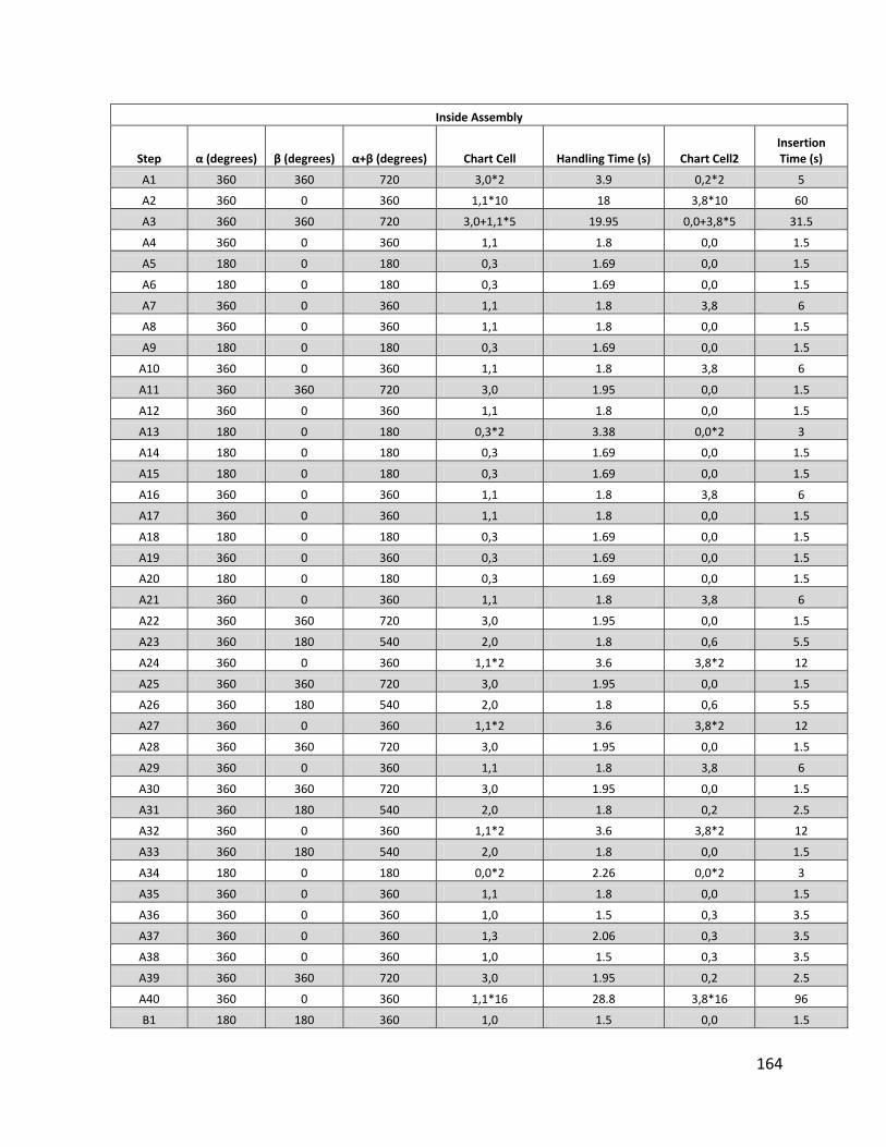
164
Inside Assembly
Step α (degrees) β (degrees) α+β (degrees) Chart Cell Handling Time (s) Chart Cell2 Insertion Time (s)
A1 360 360 720 3,0*2 3.9 0,2*2 5
A2 360 0 360 1,1*10 18 3,8*10 60
A3 360 360 720 3,0+1,1*5 19.95 0,0+3,8*5 31.5
A4 360 0 360 1,1 1.8 0,0 1.5
A5 180 0 180 0,3 1.69 0,0 1.5
A6 180 0 180 0,3 1.69 0,0 1.5
A7 360 0 360 1,1 1.8 3,8 6
A8 360 0 360 1,1 1.8 0,0 1.5
A9 180 0 180 0,3 1.69 0,0 1.5
A10 360 0 360 1,1 1.8 3,8 6
A11 360 360 720 3,0 1.95 0,0 1.5
A12 360 0 360 1,1 1.8 0,0 1.5
A13 180 0 180 0,3*2 3.38 0,0*2 3
A14 180 0 180 0,3 1.69 0,0 1.5
A15 180 0 180 0,3 1.69 0,0 1.5
A16 360 0 360 1,1 1.8 3,8 6
A17 360 0 360 1,1 1.8 0,0 1.5
A18 180 0 180 0,3 1.69 0,0 1.5
A19 360 0 360 0,3 1.69 0,0 1.5
A20 180 0 180 0,3 1.69 0,0 1.5
A21 360 0 360 1,1 1.8 3,8 6
A22 360 360 720 3,0 1.95 0,0 1.5
A23 360 180 540 2,0 1.8 0,6 5.5
A24 360 0 360 1,1*2 3.6 3,8*2 12
A25 360 360 720 3,0 1.95 0,0 1.5
A26 360 180 540 2,0 1.8 0,6 5.5
A27 360 0 360 1,1*2 3.6 3,8*2 12
A28 360 360 720 3,0 1.95 0,0 1.5
A29 360 0 360 1,1 1.8 3,8 6
A30 360 360 720 3,0 1.95 0,0 1.5
A31 360 180 540 2,0 1.8 0,2 2.5
A32 360 0 360 1,1*2 3.6 3,8*2 12
A33 360 180 540 2,0 1.8 0,0 1.5
A34 180 0 180 0,0*2 2.26 0,0*2 3
A35 360 0 360 1,1 1.8 0,0 1.5
A36 360 0 360 1,0 1.5 0,3 3.5
A37 360 0 360 1,3 2.06 0,3 3.5
A38 360 0 360 1,0 1.5 0,3 3.5
A39 360 360 720 3,0 1.95 0,2 2.5
A40 360 0 360 1,1*16 28.8 3,8*16 96
B1 180 180 360 1,0 1.5 0,0 1.5
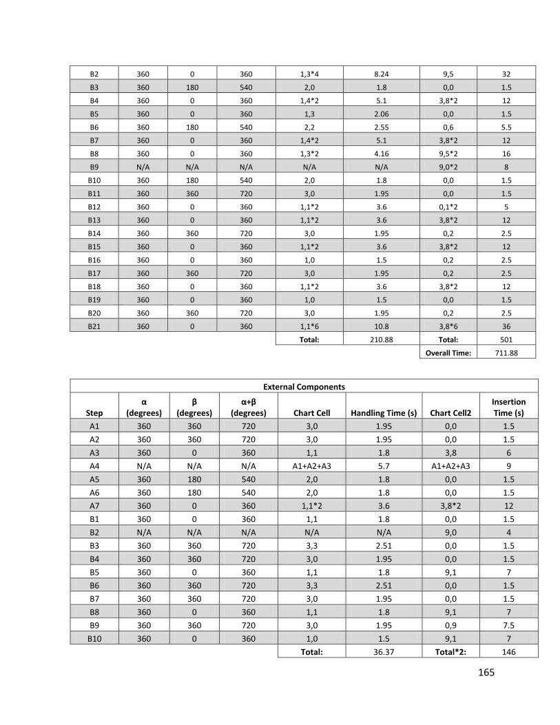
165
B2 360 0 360 1,3*4 8.24 9,5 32
B3 360 180 540 2,0 1.8 0,0 1.5
B4 360 0 360 1,4*2 5.1 3,8*2 12
B5 360 0 360 1,3 2.06 0,0 1.5
B6 360 180 540 2,2 2.55 0,6 5.5
B7 360 0 360 1,4*2 5.1 3,8*2 12
B8 360 0 360 1,3*2 4.16 9,5*2 16
B9 N/A N/A N/A N/A N/A 9,0*2 8
B10 360 180 540 2,0 1.8 0,0 1.5
B11 360 360 720 3,0 1.95 0,0 1.5
B12 360 0 360 1,1*2 3.6 0,1*2 5
B13 360 0 360 1,1*2 3.6 3,8*2 12
B14 360 360 720 3,0 1.95 0,2 2.5
B15 360 0 360 1,1*2 3.6 3,8*2 12
B16 360 0 360 1,0 1.5 0,2 2.5
B17 360 360 720 3,0 1.95 0,2 2.5
B18 360 0 360 1,1*2 3.6 3,8*2 12
B19 360 0 360 1,0 1.5 0,0 1.5
B20 360 360 720 3,0 1.95 0,2 2.5
B21 360 0 360 1,1*6 10.8 3,8*6 36
Total: 210.88 Total: 501
Overall Time: 711.88
External Components
Step α
(degrees) β
(degrees) α+β
(degrees) Chart Cell Handling Time (s) Chart Cell2 Insertion Time (s)
A1 360 360 720 3,0 1.95 0,0 1.5
A2 360 360 720 3,0 1.95 0,0 1.5
A3 360 0 360 1,1 1.8 3,8 6
A4 N/A N/A N/A A1+A2+A3 5.7 A1+A2+A3 9
A5 360 180 540 2,0 1.8 0,0 1.5
A6 360 180 540 2,0 1.8 0,0 1.5
A7 360 0 360 1,1*2 3.6 3,8*2 12
B1 360 0 360 1,1 1.8 0,0 1.5
B2 N/A N/A N/A N/A N/A 9,0 4
B3 360 360 720 3,3 2.51 0,0 1.5
B4 360 360 720 3,0 1.95 0,0 1.5
B5 360 0 360 1,1 1.8 9,1 7
B6 360 360 720 3,3 2.51 0,0 1.5
B7 360 360 720 3,0 1.95 0,0 1.5
B8 360 0 360 1,1 1.8 9,1 7
B9 360 360 720 3,0 1.95 0,9 7.5
B10 360 0 360 1,0 1.5 9,1 7
Total: 36.37 Total*2: 146
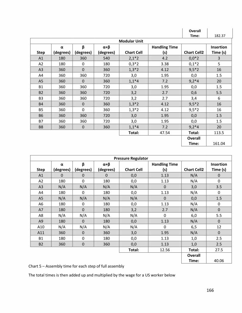
166
Overall Time: 182.37
Modular Unit
Step α
(degrees) β
(degrees) α+β
(degrees) Chart Cell Handling Time
(s) Chart Cell2 Insertion Time (s)
A1 180 360 540 2,1*2 4.2 0,0*2 3
A2 180 0 180 0,3*2 3.38 0,1*2 5
A3 360 0 360 1,3*2 4.12 9,5*2 16
A4 360 360 720 3,0 1.95 0,0 1.5
A5 360 0 360 1,1*4 7.2 9,2*4 20
B1 360 360 720 3,0 1.95 0,0 1.5
B2 360 360 720 3,2 2.7 0,6 5.5
B3 360 360 720 3,2 2.7 3,4 6
B4 360 0 360 1,3*2 4.12 9,5*2 16
B5 360 0 360 1,3*2 4.12 9,5*2 16
B6 360 360 720 3,0 1.95 0,0 1.5
B7 360 360 720 3,0 1.95 0,0 1.5
B8 360 0 360 1,1*4 7.2 9,2*4 20
Total: 47.54 Total: 113.5
Overall Time: 161.04
Pressure Regulator
Step α
(degrees) β
(degrees) α+β
(degrees) Chart Cell Handling Time
(s) Chart Cell2 Insertion Time (s)
A1 0 0 0 0,0 1.13 N/A 0
A2 180 0 180 0,0 1.13 N/A 0
A3 N/A N/A N/A N/A 0 3,0 3.5
A4 180 0 180 0,0 1.13 N/A 0
A5 N/A N/A N/A N/A 0 0,0 1.5
A6 180 0 180 0,0 1.13 N/A 0
A7 180 0 180 3,2 2.7 N/A 0
A8 N/A N/A N/A N/A 0 6,0 5.5
A9 180 0 180 0,0 1.13 N/A 0
A10 N/A N/A N/A N/A 0 6,5 12
A11 360 0 360 3,0 1.95 N/A 0
B1 180 0 180 0,0 1.13 1,0 2.5
B2 360 0 360 0,0 1.13 1,0 2.5
Total: 12.56 Total: 27.5
Overall Time: 40.06
Chart 5 – Assembly time for each step of full assembly
The total times is then added up and multiplied by the wage for a US worker below
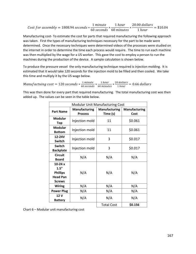
167
𝐶𝑜𝑠𝑡 𝑓𝑜𝑟 𝑎𝑠𝑠𝑒𝑚𝑏𝑙𝑦 = 1808.94 𝑠𝑒𝑐𝑜𝑛𝑑𝑠 ∗1 𝑚𝑖𝑛𝑢𝑡𝑒
60 𝑠𝑒𝑐𝑜𝑛𝑑𝑠∗
1 ℎ𝑜𝑢𝑟
60 𝑚𝑖𝑛𝑢𝑡𝑒𝑠∗20.00 𝑑𝑜𝑙𝑙𝑎𝑟𝑠
1 ℎ𝑜𝑢𝑟= $10.04
Manufacturing cost- To estimate the cost for parts that required manufacturing the following approach
was taken. First the types of manufacturing techniques necessary for the part to be made were
determined. Once the necessary techniques were determined videos of the processes were studied on
the internet in order to determine the time each process would require. The time to run each machine
was then multiplied by the wage for a US worker. This gave the cost to employ a person to run the
machines during the production of the device. A sample calculation is shown below.
To produce the pressure vessel the only manufacturing technique required is injection molding. It is
estimated that it would take 120 seconds for the injection mold to be filled and then cooled. We take
this time and multiply it by the US wage below.
𝑀𝑎𝑛𝑢𝑓𝑎𝑐𝑡𝑢𝑖𝑛𝑔 𝑐𝑜𝑠𝑡 = 120 𝑠𝑒𝑐𝑜𝑛𝑑𝑠 ∗1 𝑚𝑖𝑛𝑢𝑡𝑒
60 𝑠𝑒𝑐𝑜𝑛𝑑𝑠∗
1 ℎ𝑜𝑢𝑟
60 𝑚𝑖𝑛𝑢𝑡𝑒𝑠∗20 𝑑𝑜𝑙𝑙𝑎𝑟𝑠
1 ℎ𝑜𝑢𝑟= 0.66 𝑑𝑜𝑙𝑙𝑎𝑟𝑠
This was then done for every part that required manufacturing. The total manufacturing cost was then
added up. The values can be seen in the table below.
Modular Unit Manufacturing Cost
Part Name Manufacturing
Process Manufacturing
Time (s) Manufacturing
Cost
Modular Top
Injection mold 11 $0.061
Modular Bottom
Injection mold 11 $0.061
12-24V Switch
Injection mold 3 $0.017
Switch Backplate
Injection mold 3 $0.017
Circuit Board
N/A N/A N/A
10-24 x 1.5"
Phillips Head Pan
Screws
N/A N/A N/A
Wiring N/A N/A N/A Power Plug N/A N/A N/A
12 V Battery
N/A N/A N/A
Total Cost $0.156
Chart 6 – Modular unit manufacturing cost
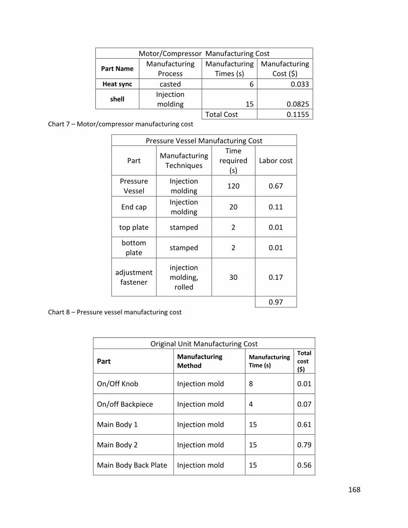
168
Motor/Compressor Manufacturing Cost
Part Name Manufacturing
Process Manufacturing
Times (s) Manufacturing
Cost ($)
Heat sync casted 6 0.033
shell Injection molding 15 0.0825
Total Cost 0.1155 Chart 7 – Motor/compressor manufacturing cost
Pressure Vessel Manufacturing Cost
Part Manufacturing
Techniques
Time required
(s) Labor cost
Pressure Vessel
Injection molding
120 0.67
End cap Injection molding
20 0.11
top plate stamped 2 0.01
bottom plate
stamped 2 0.01
adjustment fastener
injection molding,
rolled 30 0.17
0.97 Chart 8 – Pressure vessel manufacturing cost
Original Unit Manufacturing Cost
Part Manufacturing Method
Manufacturing Time (s)
Total cost ($)
On/Off Knob Injection mold 8 0.01
On/off Backpiece Injection mold 4 0.07
Main Body 1 Injection mold 15 0.61
Main Body 2 Injection mold 15 0.79
Main Body Back Plate Injection mold 15 0.56
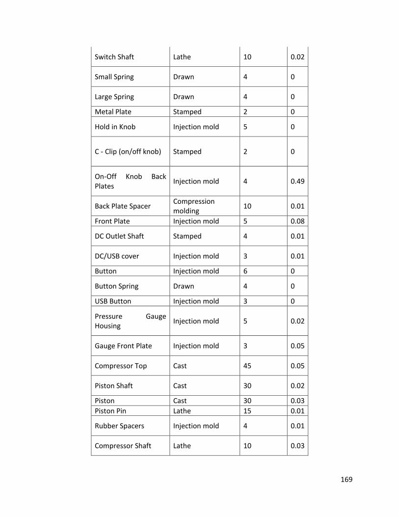
169
Switch Shaft Lathe 10 0.02
Small Spring Drawn 4 0
Large Spring Drawn 4 0
Metal Plate Stamped 2 0
Hold in Knob Injection mold 5 0
C - Clip (on/off knob) Stamped 2 0
On-Off Knob Back Plates
Injection mold 4 0.49
Back Plate Spacer Compression molding
10 0.01
Front Plate Injection mold 5 0.08
DC Outlet Shaft Stamped 4 0.01
DC/USB cover Injection mold 3 0.01
Button Injection mold 6 0
Button Spring Drawn 4 0
USB Button Injection mold 3 0
Pressure Gauge Housing
Injection mold 5 0.02
Gauge Front Plate Injection mold 3 0.05
Compressor Top Cast 45 0.05
Piston Shaft Cast 30 0.02
Piston Cast 30 0.03
Piston Pin Lathe 15 0.01
Rubber Spacers Injection mold 4 0.01
Compressor Shaft Lathe 10 0.03
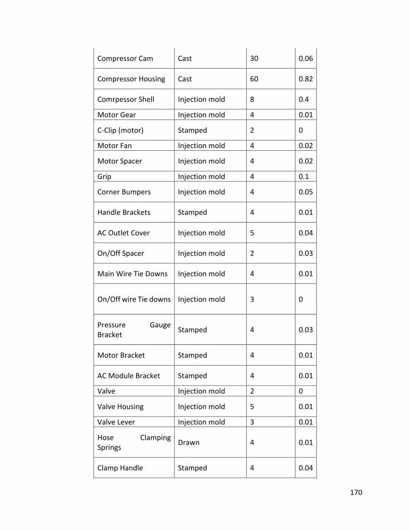
170
Compressor Cam Cast 30 0.06
Compressor Housing Cast 60 0.82
Comrpessor Shell Injection mold 8 0.4
Motor Gear Injection mold 4 0.01
C-Clip (motor) Stamped 2 0
Motor Fan Injection mold 4 0.02
Motor Spacer Injection mold 4 0.02
Grip Injection mold 4 0.1
Corner Bumpers Injection mold 4 0.05
Handle Brackets Stamped 4 0.01
AC Outlet Cover Injection mold 5 0.04
On/Off Spacer Injection mold 2 0.03
Main Wire Tie Downs Injection mold 4 0.01
On/Off wire Tie downs Injection mold 3 0
Pressure Gauge Bracket
Stamped 4 0.03
Motor Bracket Stamped 4 0.01
AC Module Bracket Stamped 4 0.01
Valve Injection mold 2 0
Valve Housing Injection mold 5 0.01
Valve Lever Injection mold 3 0.01
Hose Clamping Springs
Drawn 4 0.01
Clamp Handle Stamped 4 0.04
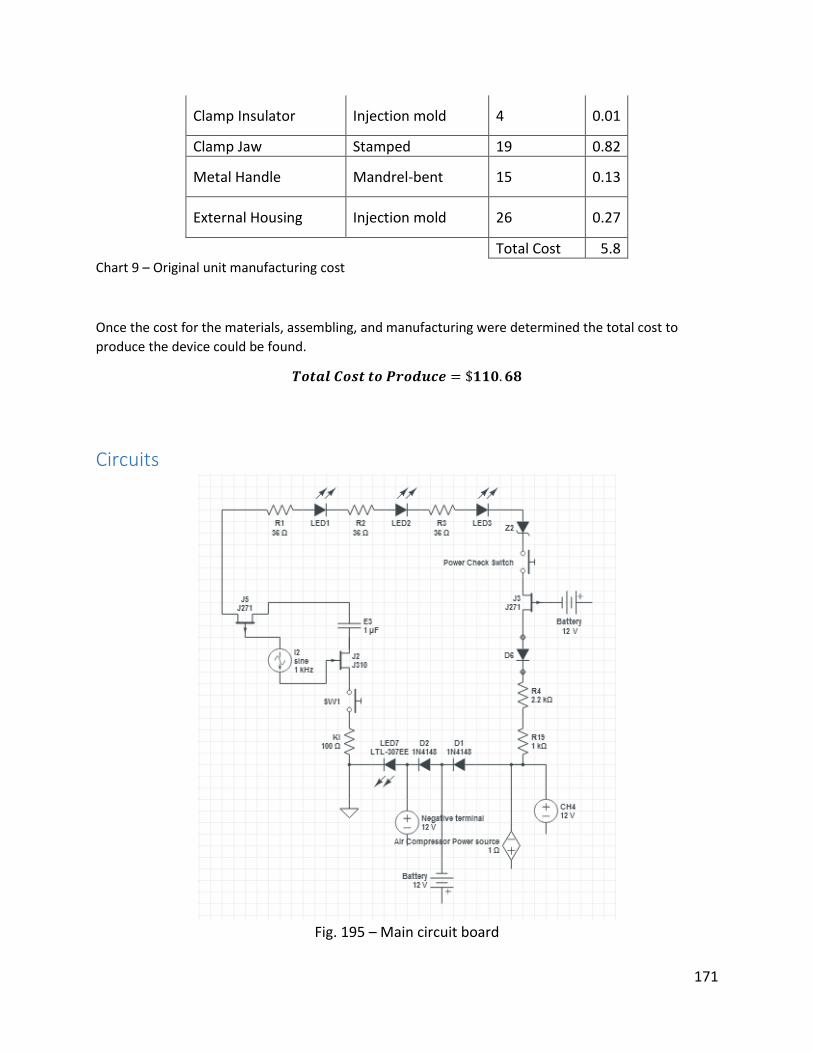
171
Clamp Insulator Injection mold 4 0.01
Clamp Jaw Stamped 19 0.82
Metal Handle Mandrel-bent 15 0.13
External Housing Injection mold 26 0.27
Total Cost 5.8 Chart 9 – Original unit manufacturing cost
Once the cost for the materials, assembling, and manufacturing were determined the total cost to
produce the device could be found.
𝑻𝒐𝒕𝒂𝒍 𝑪𝒐𝒔𝒕 𝒕𝒐 𝑷𝒓𝒐𝒅𝒖𝒄𝒆 = $𝟏𝟏𝟎. 𝟔𝟖
Circuits
Fig. 195 – Main circuit board

172
Circuit Board
This device is comprised of multiple circuit systems that are all interconnected to the main circuit board.
The main board, as represented by the larger tan shape, has all wires leading to and from it. It currently
has five LED lights that are connected directly to the board, two switches, and thirteen individual wires. It
also houses multiple resistors and capacitors to ensure operation with the right amount of power. The
wires each play an important role to make each component to work together and still allow the system
complete a closed circuit. The red wires are all positive and are connected to the positive terminal on the
battery and other mechanisms. The black wires do the same as the red, the only difference is that they all
lead and are connected to the negative terminal of the battery or grounded. The yellow wire transmits a
signal when the circuit loop is closed and transmits for things such as on/off switched and the presence
of a connecting device.
There are four switches: two on the main board and two that operate off the board. The two on the board
are connected directly to the board, the large switch controls the USB on/off position. Once the switch is
on the USB can be used as a charging device, and therefore will trigger the LED light to signal a closed
circuit. The smaller one is used to check the batteries level of power, which is connected to the three LED
lights that indicate the level of power in the battery. Each LED will light up once the necessary power is
able to pass through the resistor; the same occurs for each level of fullness. Hence the more power the
battery has the more likely for it to power the highest level of resistor. The off board switches are used
for the main on/off switch and the flashlight switch. This switch is also directly grounded to the air
compressor and pressure gauge LED. The flashlight switch is connected to a mini circuit board that holds
the LED that acts as a flashlight and once the switch is closed power is allowed to pass through and
completes the circuit, hence turning on the flashlight.
Two of the LED lights not discussed yet are the pressure gauge LED and the polarity LED. The pressure
gauge LED light is used to show that the air compressor is on and fully functional. The polarity LED light is
used as a safety feature and is used in the event that the jumper cables are incorrectly positioned. For
instance if the user accidentally were to place the red jumper cable claw and connect it to the negative
terminal the light would shine to warn you that the system will not work under these conditions.
There are six diodes that are a two-terminal electronic component that has an asymmetric transfer
characteristic. It also uses one zener diode which is a diode which allows current to pass in the forward
direction just like an ideal diode. There were three electrical impedances that measured the opposition

173
that a circuit presents to the path of a current when voltage is applied. There are also two switches that
are in the open position and are closed to allow the voltage to pass through. There are multiple resistors
and one capacitor to charge amperage ready to be released whenever necessary. There are two positive
sources that are connected to the battery and one cable that is grounded as seen in the figure above. The
power wires leading away from the system are the ones that are powering the other controls for this
system ie. flashlight, on / off switch, and USB port.
Safety The system is designed with several safety features to ensure the user is not injured during proper
operation. The compressor motor is equipped with a thermal relay that turns the motor off when the
temperature reaches 140C to prevent damage to the motor as well as a burn injury. Rubber caps are
included to seal the holes in the bottom of the main unit when the modular battery pack is not utilized.
This prevents accidental contact with the electrical circuit inside the unit, which could result in electrical
shock. The connection on the modular battery pack is designed so that the electrical contacts are
surrounded by plastic to prevent an accidental short circuit.
The device manual provides strict instructions to maximize your understanding and safety with the device.
The device should not be used in a manner inconsistent with the instructions. Avoid extreme
temperatures and do not allow the unit to freeze or get wet. Specific safety precautions are given below.
Shock Hazard
To prevent electric shock, ensure the jumper cables are attached securely to the battery terminals before
switching the unit on. Always attach the positive cable first and ground the negative cable to the chassis
to prevent arcing. When charging the unit, do not use frayed or damaged extension cords. Do not insert
foreign objects into the charging ports.
Burn Hazard
When operating the compressor, make sure the unit is in a well-ventilated area and be careful of hot
surfaces. The motor gets very hot during operation. Never use the unit around an open flame or smoke
around the unit, as the batteries contain flammable acid.

174
Burst Hazard
Do not overinflate vehicle tires using the compressor. Always read the tire sidewall to determine fill
pressure, and set the regulator accordingly. Never leave unit running unattended, as the regulator could
fail and over-inflation could occur, possibly bursting the tire.
Conclusion The changes made to the Stanley car jump starter make it a significantly better product. The Car jumper
2000 now has the ability to be used with a tractor trailer. With the new modular system the device can
either jump tractor trailers or a standard car with the turn of a knob. The new pressure regulator system
allows for any tire up to 18 liters to be filled from 0 psi to 120 psi within 12 minutes. With the built-in
contact switch the compressor turns off automatically to save power. A new 350 watt motor was added
to allow the system to be used with tractor trailer tires. The motor coupled with a cast iron heat sink
allows the motor to run continuously for 33 minutes without overheating. All of these upgrades along
with minor modifications like longer hoses make the new design a superior product. Within the allotted
budget everything was improved to meet the necessary specifications. Other potential upgrades to the
device include stronger batteries and an improved flashlight. If the batteries were to be upgraded it would
allow for even larger engines to be jump started. More capabilities could also be added to the flashlight.
A strobe effect could be added to send out a SOS signal. If the flashlight were to be made detachable it
would also greatly improve the functionality. With a larger budget these ideas could be implemented.
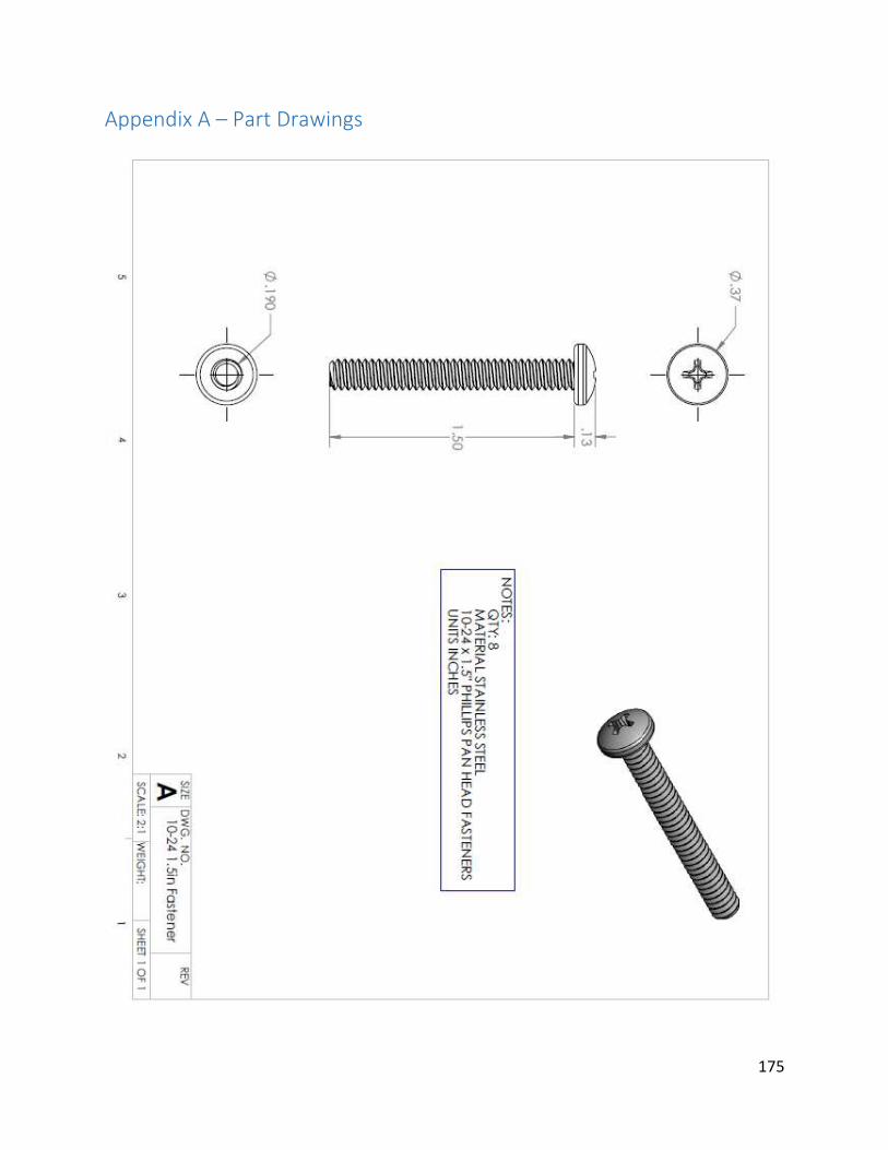
175
Appendix A – Part Drawings
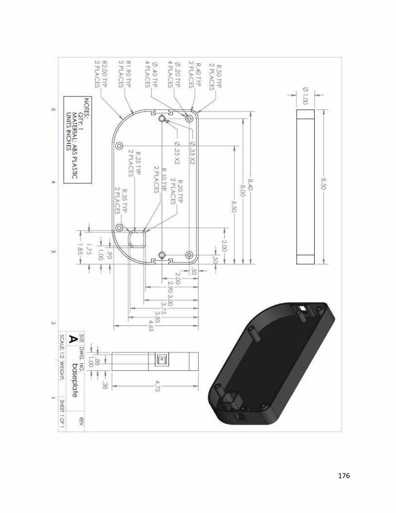
176

177
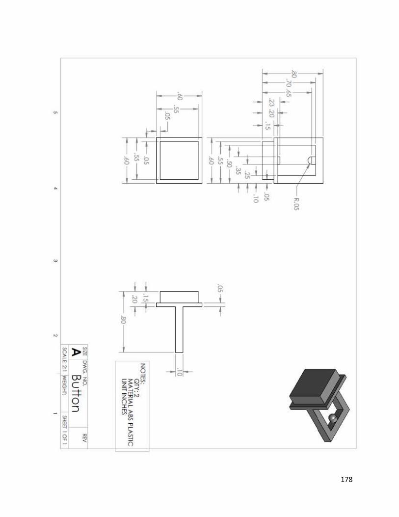
178
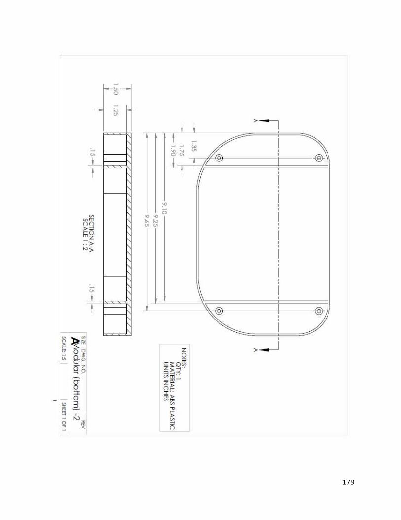
179

180
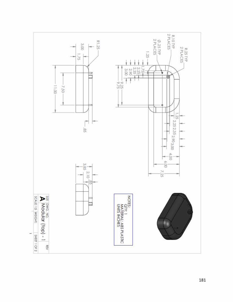
181
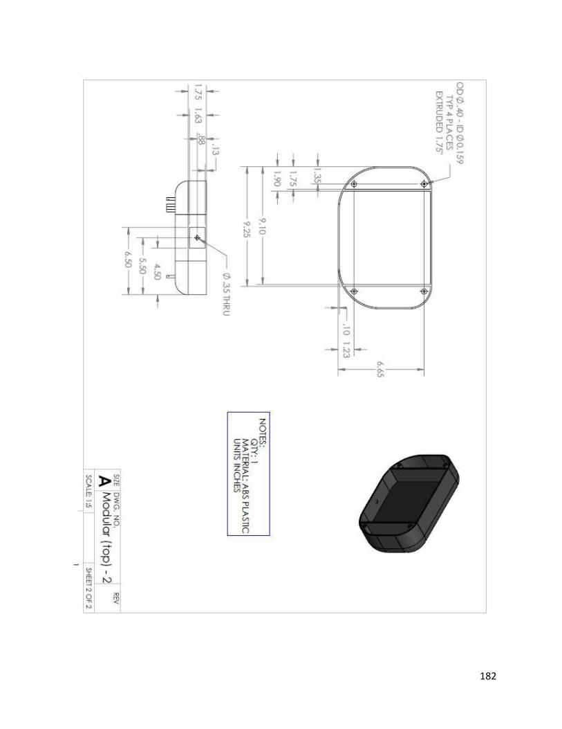
182
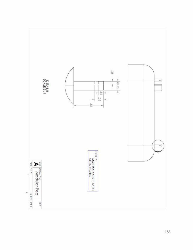
183
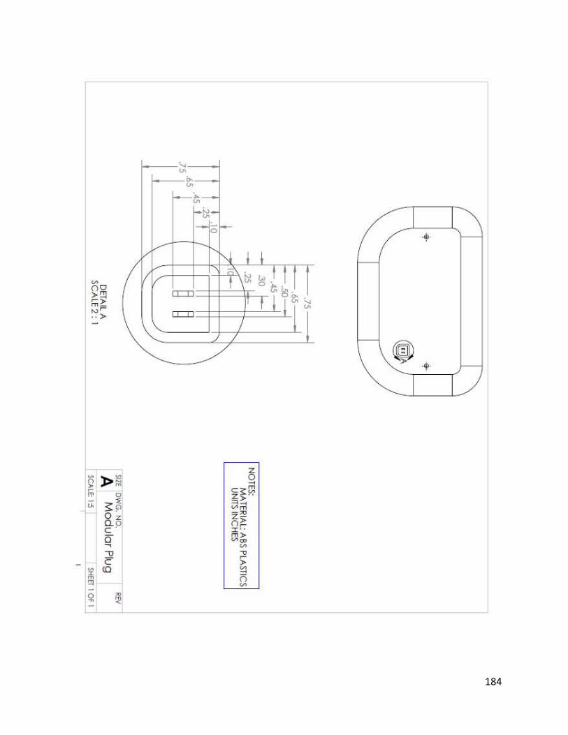
184
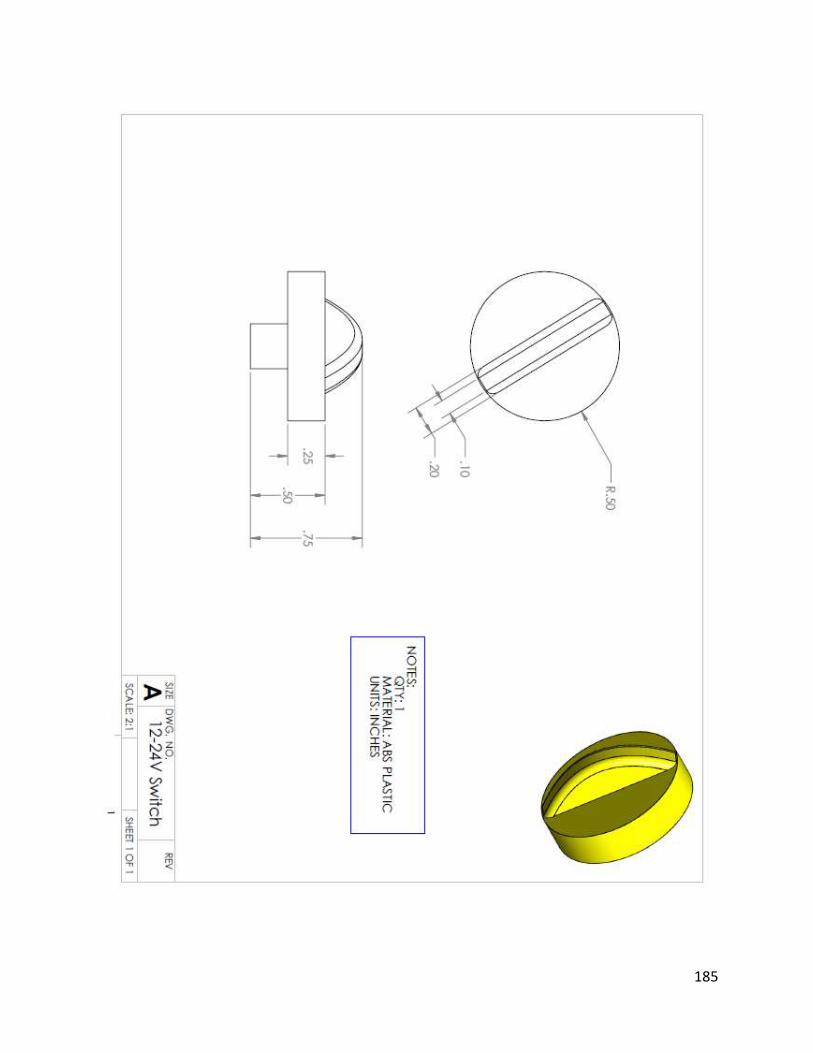
185
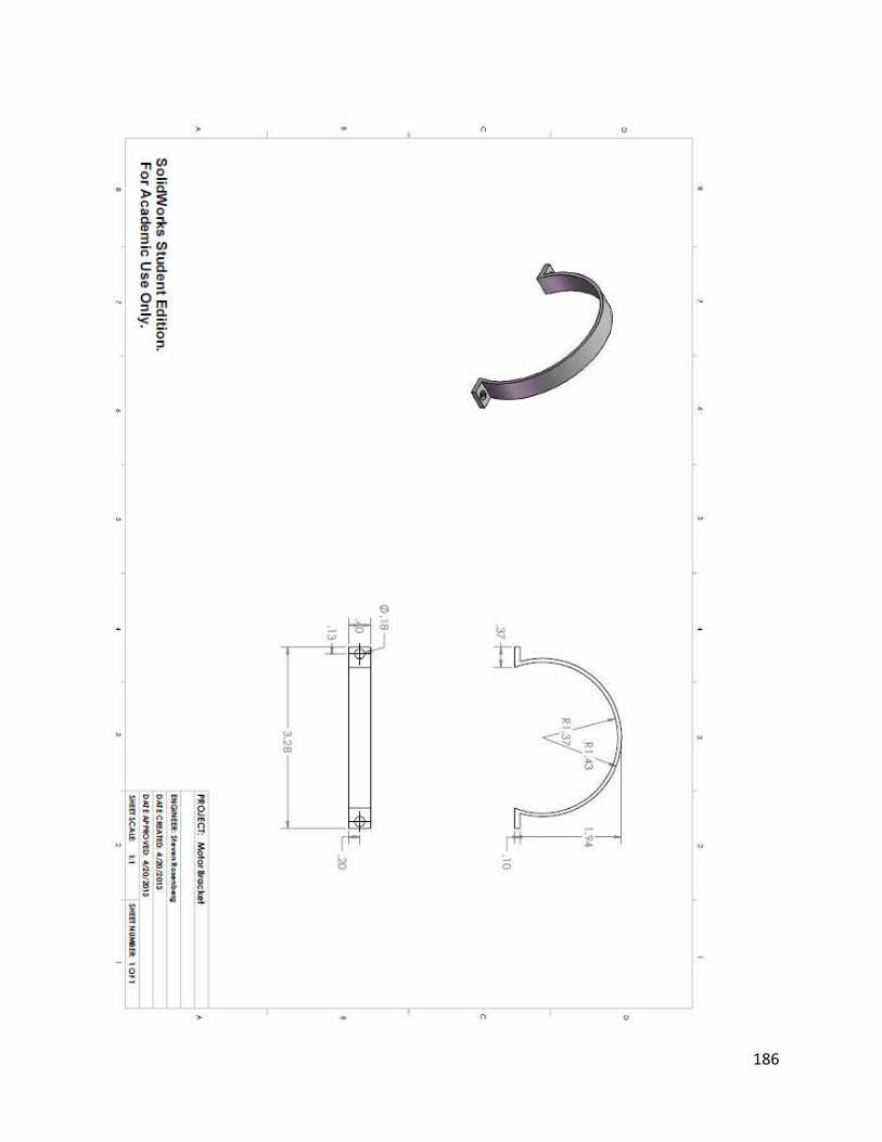
186
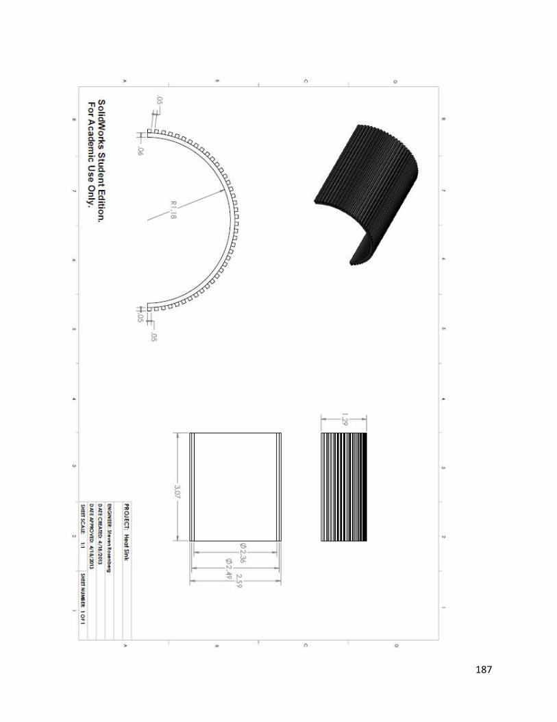
187

188
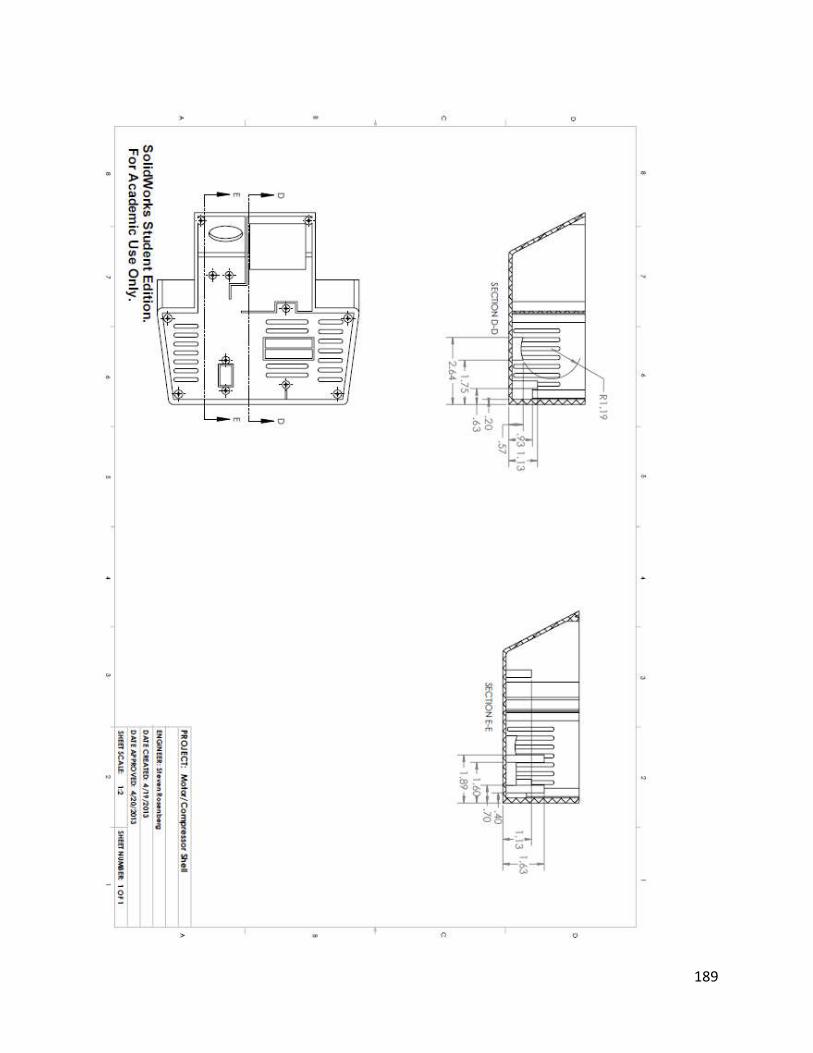
189
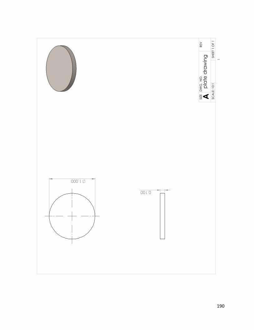
190
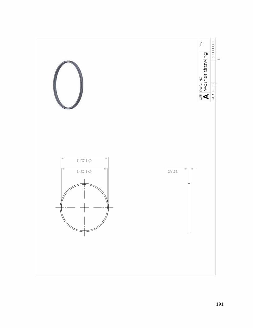
191
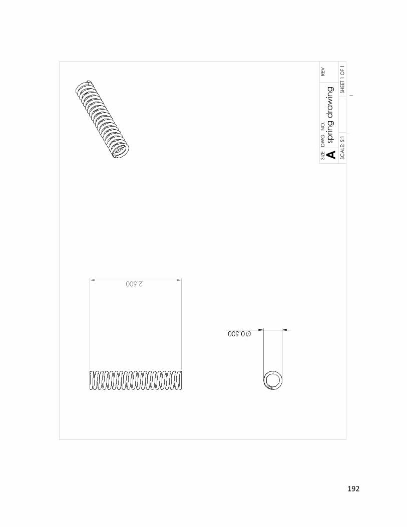
192
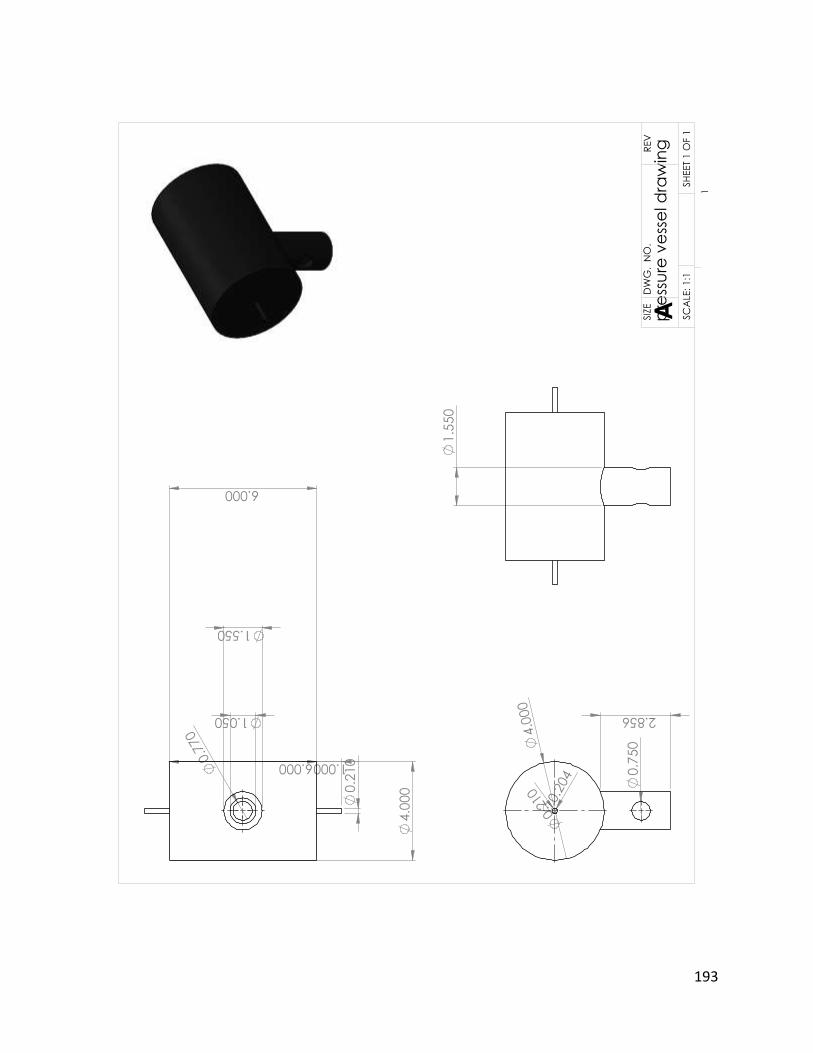
193
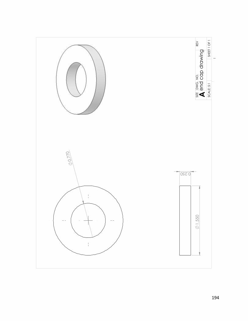
194
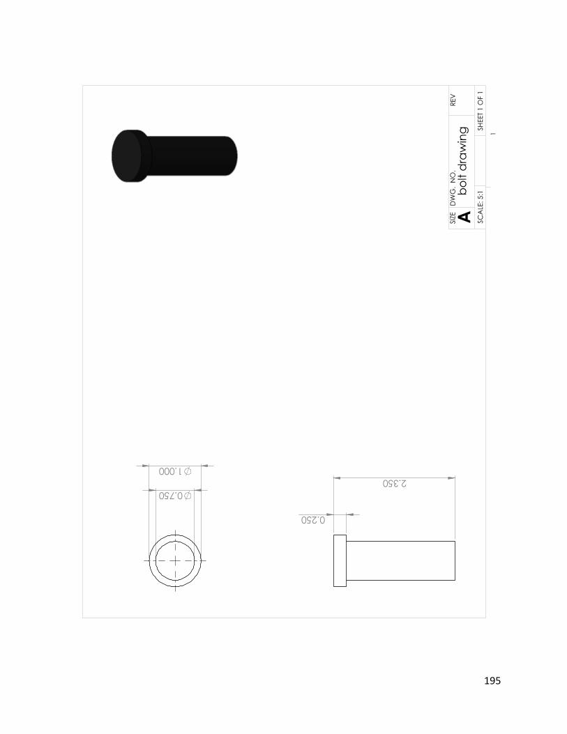
195
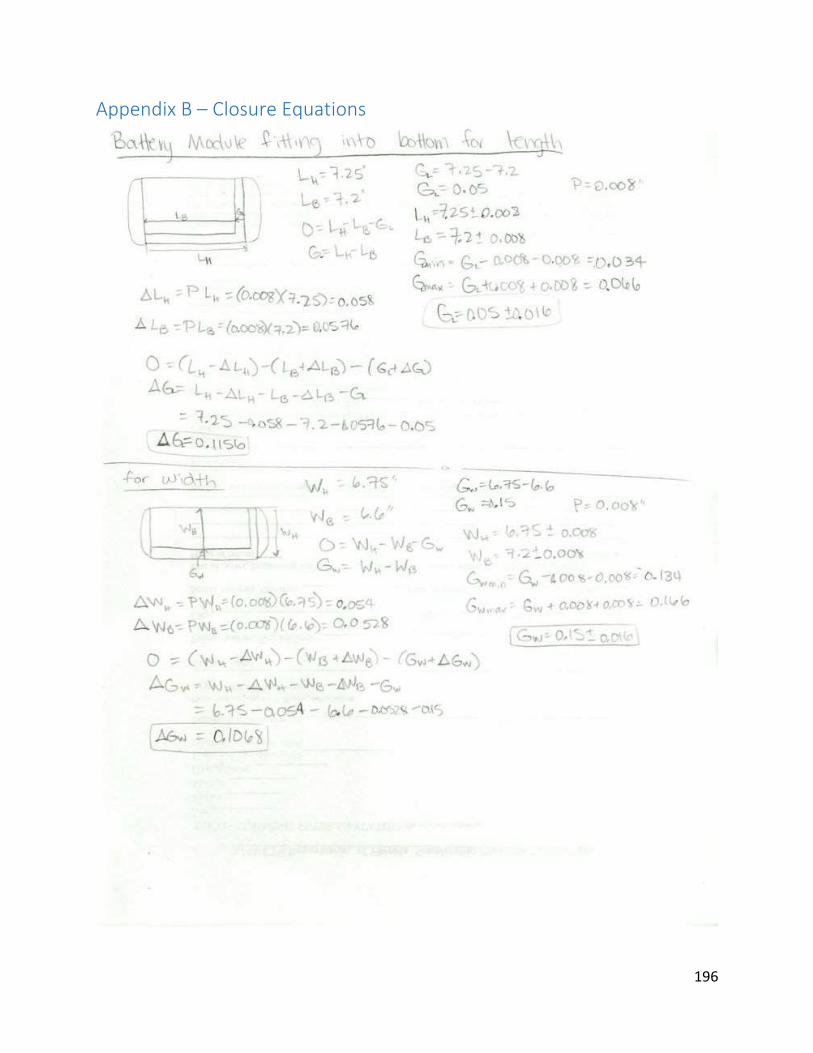
196
Appendix B – Closure Equations
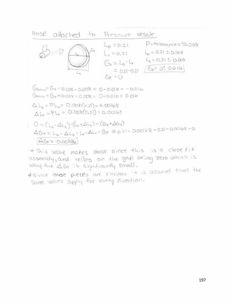
197
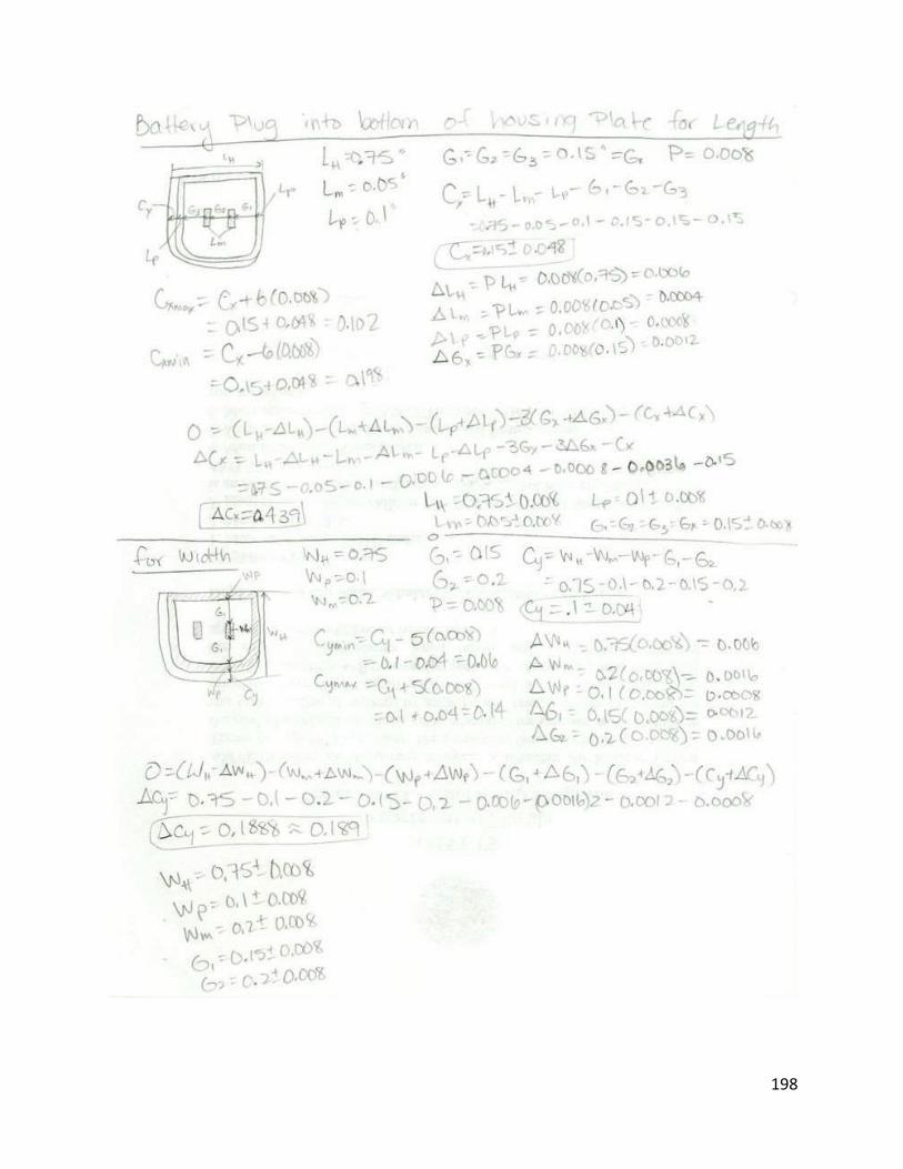
198
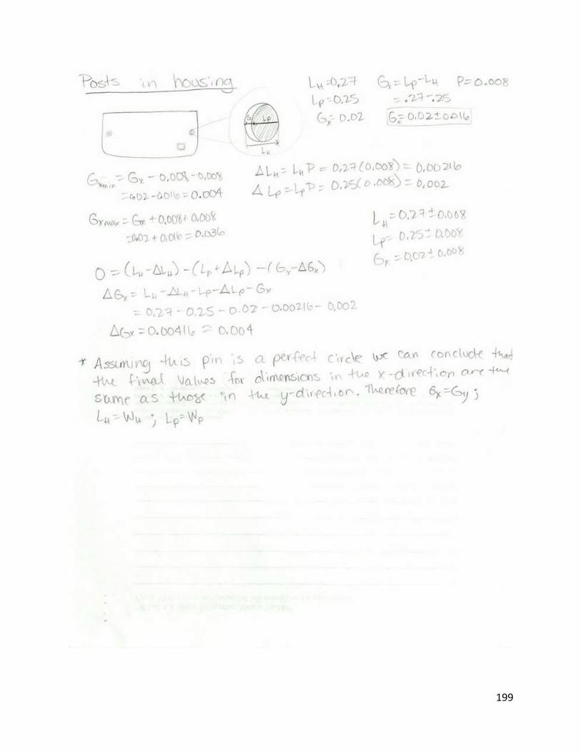
199
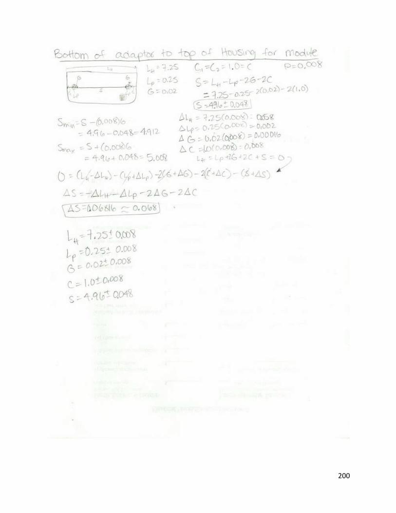
200

201

202

203

204
Appendix C - References http://www.baccusglobal.com/stanley/manuals/JUMPERS/J509%20MANUAL.pdf
https://www.circuitlab.com/editor/
http://en.wikipedia.org/wiki/Diode
http://en.wikipedia.org/wiki/Zener_diode
http://en.wikipedia.org/wiki/Electrical_impedance
http://www.ehow.co.uk/list_7377667_car-specifications-cold-cranking-amps.html
http://www.optimabatteries.com/us/en/shop/yellowtop/optima-batteries-d27f-yellowtop-starting-and-
deep-cycle-battery?gclid=CLnPv9G_-rUCFQUHnQodDzEAvQ
http://www.usb.org/developers/devclass_docs
“Stanley 500 AMP Battery Jump-Starter With Compressor Instruction Manual”. Intertek. Baccus Global
LLC. 2011.
“Shigley’s Mechanical Engineering Design”. R.G. Budynas and J.K. Nisbett. 9th Edition. McGraw-Hill. 2011
http://www.wageindicator.org/main/minimum-wages/china-custom
http://www.plasticsinfomart.com/abs-price-chart/
http://www.omnexus.com/tc/polymerselector/polymerprofiles.aspx?id=256&us=0&tab=3
http://www.steinwall.com/PDF/AA-PSU.pdf
http://www.chemicool.com/elements/copper.html
http://www.mcmaster.com/#machine-screw-fasteners/=lz8r6g
http://www.mcmaster.com/#machine-screw-
fasteners/=lz8rkohttp://www.mcmaster.com/#machine-screw-fasteners/=lz8rxs
http://www.mcmaster.com/#machine-screw-fasteners/=lz8s2b
http://www.mcmaster.com/#machine-screw-fasteners/=lz8sau

205
http://www.mcmaster.com/#machine-screw-fasteners/=lz8tr9
http://www.mcmaster.com/#machine-screw-fasteners/=lz8u4a
http://www.mcmaster.com/#machine-screw-fasteners/=lz8tya
http://www.mcmaster.com/#machine-screw-fasteners/=lz8u92
http://www.mcmaster.com/#machine-screw-fasteners/=lz8ugi
http://www.alibaba.com/product-gs/297286809/Brush_12V_DC_Motor_60ZY_.html
http://www.alibaba.com/product-gs/570199131/80ZYT03A_1_25Nm_350W_dc_electric.html
http://www.engineeringtoolbox.com/specific-heat-metals-d_152.html
http://www.engineeringtoolbox.com/overall-heat-transfer-coefficients-d_284.html
http://www.engineeringtoolbox.com/radiation-constants-d_150.html
http://www.peacesoftware.de/einigewerte/luft_e.html
http://materials.iisc.ernet.in/~ramu/Fatigue.pdf
http://www.mcmaster.com/#compression-springs/=mdqbjt
http://www.mcmaster.com/#o-rings/=mdqc34
http://www.eng-tips.com/viewthread.cfm?qid=72171
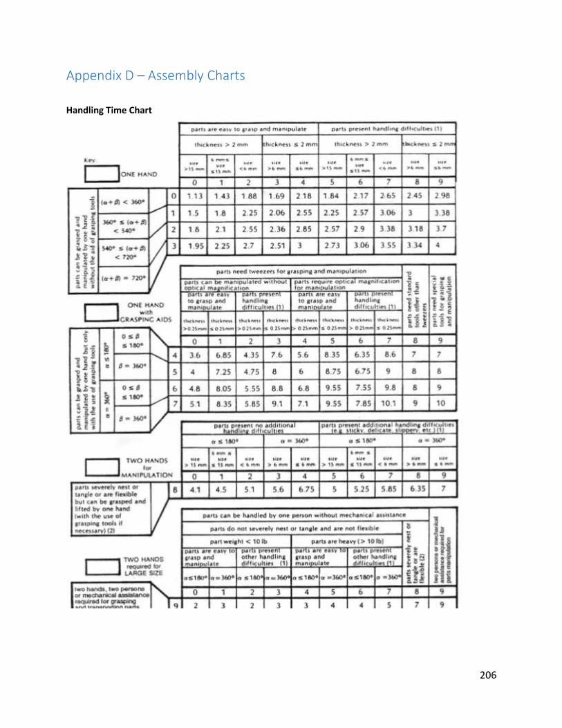
206
Appendix D – Assembly Charts
Handling Time Chart

207
Manual Insertion Time Chart
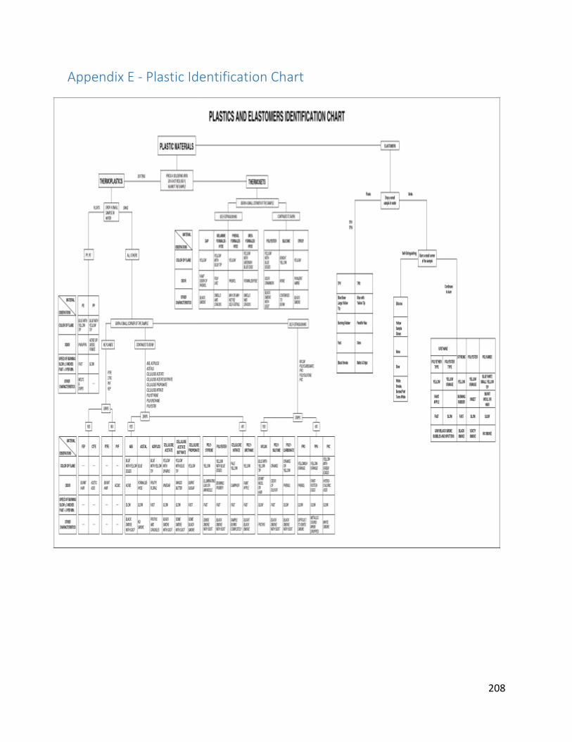
208
Appendix E - Plastic Identification Chart


![Mechanical Engineering Design Shigley 7th Edition Solutions[1]](https://img.pdfslide.tips/doc/110x75/54688b03af79592a298b45f3/mechanical-engineering-design-shigley-7th-edition-solutions1.jpg)