Embed Size (px)
Citation preview
EUROPEAN STANDARD
NORME EUROPÉENNE
EUROPÄISCHE NORM
EN 1991-1-1
April 2002
ICS 91.010.30 Supersedes ENV 1991-2-1:1995
English version
Eurocode 1: Actions on structures - Part 1-1: General actions -Densities, self-weight, imposed loads for buildings
Eurocode 1: Actions sur les structures - Partie 1-1: Actionsgénérales - Poids volumiques, poids propres, charges
d'exploitation bâtiments
Eurocode 1: Einwirkungen auf Tragwerke - Teil 1-1:Wichten, Eigengewicht und Nutzlasten im Hochbau
This European Standard was approved by CEN on 30 November 2001.
CEN members are bound to comply with the CEN/CENELEC Internal Regulations which stipulate the conditions for giving this EuropeanStandard the status of a national standard without any alteration. Up-to-date lists and bibliographical references concerning such nationalstandards may be obtained on application to the Management Centre or to any CEN member.
This European Standard exists in three official versions (English, French, German). A version in any other language made by translationunder the responsibility of a CEN member into its own language and notified to the Management Centre has the same status as the officialversions.
CEN members are the national standards bodies of Austria, Belgium, Czech Republic, Denmark, Finland, France, Germany, Greece,Iceland, Ireland, Italy, Luxembourg, Malta, Netherlands, Norway, Portugal, Spain, Sweden, Switzerland and United Kingdom.
EUROPEAN COMMITTEE FOR STANDARDIZATIONC OM ITÉ EUR OP ÉEN DE NOR M ALIS AT IONEUROPÄISCHES KOMITEE FÜR NORMUNG
Management Centre: rue de Stassart, 36 B-1050 Brussels
© 2002 CEN All rights of exploitation in any form and by any means reservedworldwide for CEN national Members.
Ref. No. EN 1991-1-1:2002 E
EN 1991-1-1:2002 (E)
2
CONTENTS
Page
FOREWORD.............................................................................................................................................. 4
BACKGROUND OF THE EUROCODE PROGRAMME....................................................................................... 4STATUS AND FIELD OF APPLICATION OF EUROCODES................................................................................. 5NATIONAL STANDARDS IMPLEMENTING EUROCODES................................................................................ 6LINKS BETWEEN EUROCODES AND HARMONISED TECHNICAL SPECIFICATIONS (ENS AND ETAS) FOR
PRODUCTS................................................................................................................................................. 6ADDITIONAL INFORMATION SPECIFIC FOR EN 1991-1-1 ............................................................................ 6NATIONAL ANNEX FOR EN 1991-1-1 ........................................................................................................ 7
SECTION 1 GENERAL ............................................................................................................................ 8
1.1 SCOPE................................................................................................................................................. 81.2 NORMATIVE REFERENCES................................................................................................................... 91.3 DISTINCTION BETWEEN PRINCIPLES AND APPLICATION RULES............................................................ 91.4 TERMS AND DEFINITIONS................................................................................................................... 101.5 SYMBOLS .......................................................................................................................................... 11
SECTION 2 CLASSIFICATION OF ACTIONS ................................................................................ 12
2.1 SELF-WEIGHT .................................................................................................................................... 122.2 IMPOSED LOADS................................................................................................................................ 12
SECTION 3 DESIGN SITUATIONS .................................................................................................... 14
3.1 GENERAL.......................................................................................................................................... 143.2 PERMANENT LOADS.......................................................................................................................... 143.3 IMPOSED LOADS................................................................................................................................ 14
3.3.1 General...................................................................................................................................... 143.3.2 Additional provisions for buildings........................................................................................... 15
SECTION 4 DENSITIES OF CONSTRUCTION AND STORED MATERIALS ........................... 16
4.1 GENERAL.......................................................................................................................................... 16
SECTION 5 SELF-WEIGHT OF CONSTRUCTION WORKS........................................................ 17
5.1 REPRESENTATION OF ACTIONS.......................................................................................................... 175.2 CHARACTERISTIC VALUES OF SELF-WEIGHT ...................................................................................... 17
5.2.1 General...................................................................................................................................... 175.2.2 Additional provisions for buildings........................................................................................... 175.2.3 Additional provisions specific for bridges................................................................................. 18
SECTION 6 IMPOSED LOADS ON BUILDINGS ........................................................................... 19
6.1 REPRESENTATION OF ACTIONS.......................................................................................................... 196.2 LOAD ARRANGEMENTS...................................................................................................................... 19
6.2.1 Floors, beams and roofs............................................................................................................ 196.2.2 Columns and walls .................................................................................................................... 19
6.3 CHARACTERISTIC VALUES OF IMPOSED LOADS................................................................................. 206.3.1 Residential, social, commercial and administration areas ....................................................... 20
6.3.1.1 Categories............................................................................................................................................206.3.1.2 Values of actions .................................................................................................................................21
6.3.2 Areas for storage and industrial activities ................................................................................ 246.3.2.1 Categories............................................................................................................................................246.3.2.2 Values for Actions...............................................................................................................................246.3.2.3 Actions induced by forklifts ................................................................................................................256.3.2.4 Actions induced by transport vehicles.................................................................................................26

EN 1991-1-1:2002 (E)
3
6.3.2.5 Actions induced by special devices for maintenance...........................................................................276.3.3 Garages and vehicle traffic areas (excluding bridges) ............................................................. 27
6.3.3.1 Categories............................................................................................................................................276.3.3.2 Values of actions .................................................................................................................................27
6.3.4 Roofs ......................................................................................................................................... 286.3.4.1 Categories............................................................................................................................................286.3.4.2 Values of actions .................................................................................................................................29
6.4 HORIZONTAL LOADS ON PARAPETS AND PARTITION WALLS ACTING AS BARRIERS.............................. 30LOADED AREAS....................................................................................................................................... 31
ANNEX A (INFORMATIVE) TABLES FOR NOMINAL DENSITY OF CONSTRUCTIONMATERIALS, AND NOMINAL DENSITY AND ANGLES OF REPOSE FOR STOREDMATERIALS............................................................................................................................................ 32
ANNEX B (INFORMATIVE) VEHICLE BARRIERS AND PARAPETS FOR CAR PARKS ......... 43
EN 1991-1-1:2002 (E)
4
Foreword
This document (EN 1991-1-1:2002) has been prepared by Technical CommitteeCEN/TC 250 "Structural Eurocodes", the secretariat of which is held by BSI.
This European Standard shall be given the status of a national standard, either bypublication of an identical text or by endorsement, at the latest by October 2002, andconflicting national standards shall be withdrawn at the latest by March 2010.
CEN/TC 250 is responsible for all Structural Eurocodes.
This document supersedes ENV 1991-2-1:1995.
The annexes A and B are informative.
According to the CEN/CENELEC Internal Regulations, the national standardsorganizations of the following countries are bound to implement this EuropeanStandard: Austria, Belgium, Czech Republic, Denmark, Finland, France, Germany,Greece, Iceland, Ireland, Italy, Luxembourg, Malta, Netherlands, Norway, Portugal,Spain, Sweden, Switzerland and the United Kingdom.
Background of the Eurocode programme
In 1975, the Commission of the European Community decided on an action programmein the field of construction, based on article 95 of the Treaty. The objective of theprogramme was the elimination of technical obstacles to trade and the harmonisation oftechnical specifications.
Within this action programme, the Commission took the initiative to establish a set ofharmonised technical rules for the design of construction works which, in a first stage,would serve as an alternative to the national rules in force in the Member States and,ultimately, would replace them.
For fifteen years, the Commission, with the help of a Steering Committee withRepresentatives of Member States, conducted the development of the Eurocodesprogramme, which led to the first generation of European codes in the 1980s.
In 1989, the Commission and the Member States of the EU and EFTA decided, on thebasis of an agreement1 between the Commission and CEN, to transfer the preparationand the publication of the Eurocodes to CEN through a series of Mandates, in order toprovide them with a future status of European Standard (EN). This links de facto theEurocodes with the provisions of all the Council’s Directives and/or Commission’sDecisions dealing with European standards (e.g. the Council Directive 89/106/EEC on
1 Agreement between the Commission of the European Communities and the European Committee for Standardisation (CEN)
concerning the work on EUROCODES for the design of building and civil engineering works (BC/CEN/03/89).

EN 1991-1-1:2002 (E)
5
construction products - CPD - and Council Directives 93/37/EEC, 92/50/EEC and89/440/EEC on public works and services and equivalent EFTA Directives initiated inpursuit of setting up the internal market).
The Structural Eurocode programme comprises the following standards generallyconsisting of a number of Parts:
EN 1990 Eurocode : Basis of Structural DesignEN 1991 Eurocode 1: Actions on structuresEN 1992 Eurocode 2: Design of concrete structuresEN 1993 Eurocode 3: Design of steel structuresEN 1994 Eurocode 4: Design of composite steel and concrete structuresEN 1995 Eurocode 5: Design of timber structuresEN 1996 Eurocode 6: Design of masonry structuresEN 1997 Eurocode 7: Geotechnical designEN 1998 Eurocode 8: Design of structures for earthquake resistanceEN 1999 Eurocode 9: Design of aluminium structures
Eurocode standards recognise the responsibility of regulatory authorities in eachMember State and have safeguarded their right to determine values related to regulatorysafety matters at national level where these continue to vary from State to State.
Status and field of application of Eurocodes
The Member States of the EU and EFTA recognise that Eurocodes serve as referencedocuments for the following purposes:
– as a means to prove compliance of building and civil engineering works with theessential requirements of Council Directive 89/106/EEC, particularly EssentialRequirement N°1 – Mechanical resistance and stability – and Essential RequirementN°2 – Safety in case of fire ;
– as a basis for specifying contracts for construction works and related engineeringservices ;
– as a framework for drawing up harmonised technical specifications for constructionproducts (ENs and ETAs)
The Eurocodes, as far as they concern the construction works themselves, have a directrelationship with the Interpretative Documents2 referred to in Article 12 of the CPD,although they are of a different nature from harmonised product standards3. Therefore,technical aspects arising from the Eurocodes work need to be adequately considered by 2 According to Art. 3.3 of the CPD, the essential requirements (ERs) shall be given concrete form in interpretative documents for
the creation of the necessary links between the essential requirements and the mandates for harmonised ENs and ETAGs/ETAs.3 According to Art. 12 of the CPD the interpretative documents shall :a) give concrete form to the essential requirements by harmonising the terminology and the technical bases and indicating classes or levels
for each requirement where necessary ;b) indicate methods of correlating these classes or levels of requirement with the technical specifications, e.g. methods of calculation and
of proof, technical rules for project design, etc. ;c) serve as a reference for the establishment of harmonised standards and guidelines for European technical approvals.The Eurocodes, de facto, play a similar role in the field of the ER 1 and a part of ER 2.

EN 1991-1-1:2002 (E)
6
CEN Technical Committees and/or EOTA Working Groups working on productstandards with a view to achieving full compatibility of these technical specificationswith the Eurocodes.
The Eurocode standards provide common structural design rules for everyday use forthe design of whole structures and component products of both a traditional and aninnovative nature. Unusual forms of construction or design conditions are notspecifically covered and additional expert consideration will be required by the designerin such cases.
National Standards implementing Eurocodes
The National Standards implementing Eurocodes will comprise the full text of theEurocode (including any annexes), as published by CEN, which may be preceded by aNational title page and National foreword, and may be followed by a National annex.
The National annex may only contain information on those parameters which are leftopen in the Eurocode for national choice, known as Nationally Determined Parameters,to be used for the design of buildings and civil engineering works to be constructed inthe country concerned, i.e. :– values and/or classes where alternatives are given in the Eurocode,– values to be used where a symbol only is given in the Eurocode,– country specific data (geographical, climatic, etc.), e.g. snow map,– the procedure to be used where alternative procedures are given in the Eurocode, . It may also contain– decisions on the application of informative annexes,– references to non-contradictory complementary information to assist the user toapply the Eurocode.
Links between Eurocodes and harmonised technical specifications (ENs andETAs) for products
There is a need for consistency between the harmonised technical specifications forconstruction products and the technical rules for works4. Furthermore, all theinformation accompanying the CE Marking of the construction products which refer toEurocodes should clearly mention which Nationally Determined Parameters have beentaken into account.
Additional information specific for EN 1991-1-1
EN 1991-1-1 gives design guidance and actions for the structural design of buildingsand civil engineering works, including the following aspects:– densities of construction materials and stored materials ;– self-weight of construction elements, and– imposed loads for buildings.
4 see Art.3.3 and Art.12 of the CPD, as well as clauses 4.2, 4.3.1, 4.3.2 and 5.2 of ID 1.

EN 1991-1-1:2002 (E)
7
EN 1991-1-1 is intended for clients, designers, contractors and public authorities.
EN 1991-1-1 is intended to be used with EN 1990, the other Parts of EN 1991 and EN1992 to EN 1999 for the design of structures.
National annex for EN 1991-1-1
This standard gives alternative procedures, values and recommendations for classes withnotes indicating where National choices have to be made, therefore the NationalStandard implementing EN 1991-1-1 should have a National Annex containing allNationally Determined Parameters to be used for the design of buildings and civilengineering works to be constructed in the relevant country.
National choice is allowed in EN 1991-1-1 through:
– 2.2(3),– 5.2.3(1) to 5.2.3(5),– 6.3.1.1 (Table 6.1),– 6.3.1.2(1)P (Table 6.2),– 6.3.1.2(10) & (11),– 6.3.2.2 (1)P (Table 6.4),– 6.3.2.2 (3),– 6.3.3.2(1) (Table 6.8),– 6.3.4.2 (Table 6.10) and– 6.4 (1)(P) (Table 6.12)
EN 1991-1-1:2002 (E)
8
Section 1 General
1.1 Scope
(1) EN 1991-1-1 gives design guidance and actions for the structural design of buildingsand civil engineering works including some geotechnical aspects for the followingsubjects:
- Densities of construction materials and stored materials;
- Self-weight of construction works;
- Imposed loads for buildings.
(2) Section 4 and Annex A give nominal values for densities of specific buildingmaterials, additional materials for bridges and stored materials. In addition for specificmaterials the angle of repose is provided.
(3) Section 5 provides methods for the assessment of the characteristic values of self-weight of construction works.
(4) Section 6 gives characteristic values of imposed loads for floors and roofs accordingto category of use in the following areas in buildings:- residential, social, commercial and administration areas;- garage and vehicle traffic areas;- areas for storage and industrial activities;- roofs;- helicopter landing areas. (5) The loads on traffic areas given in Section 6 refer to vehicles up to a gross vehicleweight of 160 kN. The design for traffic areas for heavy vehicles of more than 160 kNgross weight needs to be agreed with the relevant authority. Further information may beobtained from EN 1991-2. (6) For barriers or walls having the function of barriers, horizontal forces are given inSection 6. Annex B gives additional guidance for vehicle barriers in car parks. NOTE Forces due to vehicle impact are specified in EN 1991-1-7 and EN 1991-2. (7) For the design situations and effects of actions in silos and tanks caused by water orother materials see EN 1991-3.

EN 1991-1-1:2002 (E)
9
1.2 Normative References This European Standard incorporates by dated or undated reference provisions from otherpublications. These normative references are cited at the appropriate places in the text andthe publications are listed hereafter. For dated references, subsequent amendments to, orrevisions of, any of these publications apply to this European Standard only whenincorporated in it by amendment or revision. For undated references the latest edition ofthe publication referred to applies (including amendments). NOTE 1 The Eurocodes were published as European Prestandards. The following European Standardswhich are published or in preparation are cited in normative clauses : EN 1990 Eurocode : Basis of Structural Design EN 1991-1-7 Eurocode 1: Actions on structures: Part 1-7: Accidental actions from
impact and explosions EN 1991-2 Eurocode 1: Actions on structures: Part 2:Traffic loads on bridges EN 1991-3 Eurocode 1: Actions on structures: Part 3: Actions induced by cranes
and machinery EN 1991-4 Eurocode 1: Actions on structures: Part 4: Actions in silos and tanks NOTE 2 The Eurocodes were published as European Prestandards. The following European Standardswhich are published or in preparation are cited in NOTES to normative clauses : EN 1991-1-3 Eurocode 1: Actions on structures: Part 1-3: Snow loads EN 1991-1-4 Eurocode 1: Actions on structures: Part 1-4: Wind actions EN 1991-1-6 Eurocode 1:Actions on structures: Part 1-6: Actions during execution
1.3 Distinction between Principles and Application Rules (1) Depending on the character of the individual clauses, distinction is made in this Partbetween Principles and Application Rules. (2) The Principles comprise: - general statements and definitions for which there is no alternative, as well as- requirements and analytical models for which no alternative is permitted unless
specifically stated.
(3) The Principles are identified by the letter P following the paragraph number.
(4) The Application Rules are generally recognised rules which comply with thePrinciples and satisfy their requirements.
(5) It is permissible to use alternative design rules different from the Application Rulesgiven in EN 1991-1-1 for works, provided that it is shown that the alternative rulesaccord with the relevant Principles and are at least equivalent with regard to thestructural safety, serviceability and durability which would be expected when using theEurocodes.
NOTE If an alternative design rule is substituted for an Application Rule, the resulting design cannot beclaimed to be wholly in accordance with EN 1991-1-1 although the design will remain in accordance with

EN 1991-1-1:2002 (E)
10
the Principles of EN 1991-1-1. When EN 1991-1-1 is used in respect of a property listed in an Annex Z ofa product standard or an ETAG, the use of an alternative design rule may not be acceptable for CEmarking.
(6) In this Part the Application Rules are identified by a number in brackets, e.g. as thisclause.
1.4 Terms and definitions
For the purposes of this European Standard, the terms and definitions given in ISO2394, ISO 3898, ISO 8930 and the following apply. Additionally for the purposes of thisstandard a basic list of terms and definitions is provided in EN 1990, 1.5.
1.4.1bulk weight densitythe bulk weight density is the overall weight per unit volume of a material, including anormal distribution of micro-voids, voids and pores
NOTE: In everyday usage this term is frequently abbreviated to “density” (which is strictly mass per unitvolume).
1.4.2angle of reposethe angle of repose is the angle which the natural slope of the sides of a heaped pile ofloose material makes to the horizontal
1.4.3gross weight of vehiclethe gross weight of a vehicle includes the self-weight of the vehicle together with themaximum weight of the goods it is permitted to carry
1.4.4structural elementsstructural elements comprise the primary structural frame and supporting structures. Forbridges, structural elements comprise girders, structural slabs and elements providingsupport such as cable stays
1.4.5non structural elementsnon structural elements are those that include completion and finishing elementsconnected with the structure, including road surfacing and non-structural parapets. Theyalso include services and machinery fixed permanently to, or within, the structure

EN 1991-1-1:2002 (E)
11
1.4.6partitionsnon load bearing walls
1.4.7movable partitionsmovable partitions are those which can be moved on the floor, be added or removed orre-built at another place
1.5 Symbols
(1) For the purposes of this European standard, the following symbols apply.
NOTE The notation used is based on ISO 3898: 1997.
(2) A basic list of symbols is provided in EN 1990 clause 1.6 and the additionalnotations below are specific to this part of EN 1991.
Latin upper case letters
A loaded areaA0 basic areaQk characteristic value of a variable concentrated load
Latin lower case letters
gk weight per unit area, or weight per unit lengthn number of storeysqk characteristic value of a uniformly distributed load, or line load
Lower case Greek letters
A reduction factorn reduction factor bulk weight density dynamic magnification factor0 factor for combination value of a variable action, see table A.1.1 of EN 1990 angle of repose (degrees)
EN 1991-1-1:2002 (E)
12
Section 2 Classification of actions
2.1 Self-weight
(1) The self-weight of construction works should be classified as a permanent fixedaction, see EN 1990, 1.5.3 and 4.1.1.
(2) Where this self-weight can vary in time, it should be taken into account by the upperand lower characteristic values (see EN 1990, 4.1.2). However, in some cases where it isfree (e.g. for movable partitions, see 6.3.1.2(8)), it should be treated as an additionalimposed load.
NOTE This applies in particular when the "permanent" actions may be favourable.
(3)P The loads due to ballast shall be considered as permanent actions and possibleredistributions of ballast shall be taken into account in the design, see 5.2.2 (1) and (2).
(4)P The earth loads on roofs and terraces shall be considered as permanent actions.
(5) With regard to 2.1(3)P and 2.1(4)P, the design should consider variations inmoisture content and variation in depth, that may be caused by uncontrolledaccumulation during the design life of the structure.
NOTE For detailed information on earth pressures see EN 1997.
2.2 Imposed loads
(1)P Imposed loads shall be classified as variable free actions, unless otherwisespecified in this standard, see EN 1990, 1.5.3 and 4.1.1.
NOTE For imposed loads on bridges see EN 1991-2.
(2) When considering the accidental design situation where impact from vehicles oraccidental loads from machines may be relevant, these loads should be taken from EN1991-1-7.
(3) Imposed loads should be taken into account as quasi-static actions (see EN 1990,1.5.3.13). The load models may include dynamic effects if there is no risk of resonanceor other significant dynamic response of the structure, see EN 1992 to EN 1999. Ifresonance effects from syncronised rythmical movement of people or dancing orjumping may be expected, the load model should be determined for special dynamicanalysis.
NOTE The procedure to be used may be given in the National annex.

EN 1991-1-1:2002 (E)
13
(4) When considering forklifts and helicopters, the additional loadings due to massesand inertial forces caused by fluctuating effects should be considered. These effects aretaken into account by a dynamic magnification factor which is applied to the staticload values, as shown in expression (6.3).
(5)P Actions which cause significant acceleration of the structure or structural membersshall be classified as dynamic actions and shall be considered using a dynamic analysis.

EN 1991-1-1:2002 (E)
14
Section 3 Design situations
3.1 General
(1)P The relevant permanent and imposed loads shall be determined for each designsituation identified in accordance with EN 1990, 3.2.
3.2 Permanent loads
(1) The total self-weight of structural and non-structural members should be taken intoaccount in combinations of actions as a single action.
NOTE See EN 1990 Table A1.2 (B) Note 3.
(2) For areas where it is intended to remove or add structural or non-structural elements,the critical load cases should be taken into account in the design.
(3) The self-weight of new coatings and/or distribution conduits that are intended to beadded after execution should be taken into account in design situations (see 5.2).
(4)P The water level shall be taken into account for the relevant design situations.
NOTE See EN 1997.
(5) The source and moisture content of bulk materials should be considered in designsituations of buildings used for storage purposes.
NOTE The values for the densities provided in Annex A are for materials in the dry state.
3.3 Imposed loads
3.3.1 General
(1)P For areas which are intended to be subjected to different categories of loadings thedesign shall consider the most critical load case.
(2)P In design situations when imposed loads act simultaneously with other variableactions (e.g actions induced by wind, snow, cranes or machinery), the total imposedloads considered in the load case shall be considered as a single action.
(3) Where the number of load variations or the effects of vibrations may cause fatigue, afatigue load model should be established.
(4) For structures susceptible to vibrations, dynamic models of imposed loads should beconsidered where relevant. The design procedure is given in EN 1990 clause 5.1.3.

EN 1991-1-1:2002 (E)
15
3.3.2 Additional provisions for buildings
(1) On roofs, imposed loads, and snow loads or wind actions should not be appliedtogether simultaneously.
(2)P When the imposed load is considered as an accompanying action, in accordancewith EN 1990, only one of the two factors (EN 1990, Table A1.1) and n (6.3.1.2(11)) shall be applied.
(3) For dynamic loads caused by machinery see EN 1991-3.
(4) The imposed loads to be considered for serviceability limit state verifications shouldbe specified in accordance with the service conditions and the requirements concerningthe performance of the structure.
EN 1991-1-1:2002 (E)
16
Section 4 Densities of construction and stored materials
4.1 General
(1) Characteristic values of densities of construction and stored materials should bespecified. Mean values should be used as characteristic values. See however 4.1(2) and4.1(3).
NOTE Annex A gives mean values for densities and angles of repose for stored materials. When a rangeis given it is assumed that the mean value will be highly dependent on the source of the material and maybe selected considering each individual project.
(2) For materials (e.g. new and innovative materials) which are not covered by theTables in Annex A, the characteristic value of the density should be determined inaccordance with EN 1990 clause 4.1.2 and agreed for each individual project.
(3) Where materials are used with a significant scatter of densities e.g. due to theirsource, water content etc, the characteristic value of these densities should be assessedin accordance with EN 1990 clause 4.1.2.
(4) If a reliable direct assessment of the densities is carried out, then these values may beused.
NOTE EN 1990 Annex D may be used.

EN 1991-1-1:2002 (E)
17
Section 5 Self-weight of construction works
5.1 Representation of actions
(1) The self-weight of the construction works should in most cases, be represented by asingle characteristic value and be calculated on the basis of the nominal dimensions andthe characteristic values of the densities.
(2) The self weight of the construction works includes the structure and non-structuralelements including fixed services as well as the weight of earth and ballast.
(3) Non-structural elements include:- roofing ;- surfacing and coverings ;- partitions and linings ;- hand rails, safety barriers, parapets and kerbs ;- wall cladding ;- suspended ceilings- thermal insulation ;- bridge furniture;- fixed services (see 5.1.(4)).
NOTE For information on fixed machinery see EN 1991-3. For other industrial equipment (e.g. safes) themanufacturer should be consulted.
(4) Fixed services include :- equipments for lifts and moving stairways ;- heating, ventilating and air conditioning equipment ;- electrical equipment ;- pipes without their contents ;- cable trunking and conduits.
(5)P Loads due to movable partitions shall be treated as imposed loads, see 5.2.2(2)Pand 6.3.1.2(8).
5.2 Characteristic values of self-weight
5.2.1 General
(1)P The determination of the characteristic values of self-weight, and of the dimensionsand densities shall be in accordance with EN 1990, 4.1.2.
(2) Nominal dimensions should be those as shown on the drawings.
5.2.2 Additional provisions for buildings
(1) For manufactured elements such as flooring systems, facades and ceilings, lifts andequipment for buildings, data may be provided by the manufacturer.
EN 1991-1-1:2002 (E)
18
(2)P For determining the effect of the self-weight due to movable partitions, anequivalent uniformly distributed load shall be used and added to the imposed load, see6.3.1.2 (8).
5.2.3 Additional provisions specific for bridges
(1) The upper and lower characteristic values of densities for non structural parts, suchas ballast on railway bridges, or fill above buried structures such as culverts, should betaken into account if the material is expected to consolidate, become saturated orotherwise change its properties, during use.
NOTE Suitable values may be given in the National annex.
(2) The nominal depth of ballast on railway bridges should be specified. To determinethe upper and lower characteristic values of the depth of ballast on railway bridges adeviation from the nominal depth of 30 % should be taken into account.
NOTE A suitable value may be given in the National annex
(3) To determine the upper and lower characteristic values of self-weight ofwaterproofing, surfacing and other coatings for bridges, where the variability of theirthickness may be high, a deviation of the total thickness from the nominal or otherspecified values should be taken into account. Unless otherwise specified, this deviationshould be taken equal to ± 20 % if a post-execution coating is included in the nominalvalue, and to + 40 % and – 20 % if such a coating is not included.
NOTE Suitable specifications may be given in the National annex.
(4) For the self-weight of cables, pipes and service ducts, the upper and lowercharacteristic values should be taken into account. Unless otherwise specified, adeviation from the mean value of the self-weight of ± 20 % should be taken intoaccount.
NOTE Suitable specifications may be given in the National annex. See also EN 1990, 4.1.2(4)
(5) For the self-weight of other non structural elements such as :- hand rails, safety barriers, parapets, kerbs and other bridge funiture,- joints/fasteners,- void formers, the characteristic values should be taken equal to the nominal values unless otherwisespecified. NOTE Suitable specifications may be given in the National annex. An allowance for voids filling withwater may be made depending on the project.
EN 1991-1-1:2002 (E)
19
Section 6 Imposed loads on buildings 6.1 Representation of actions (1) Imposed loads on buildings are those arising from occupancy. Values given in thisSection, include:- normal use by persons;- furniture and moveable objects (e.g. moveable partitions, storage, the contents of
containers);- vehicles;- anticipating rare events, such as concentrations of persons or of furniture, or the
moving or stacking of objects which may occur during reorganization orredecoration.
(2) The imposed loads specified in this part are modelled by uniformly distributed loads,line loads or concentrated loads or combinations of these loads.
(3) For the determination of the imposed loads, floor and roof areas in buildings shouldbe sub-divided into categories according to their use.
(4) Heavy equipment (e.g. in communal kitchens, radiology rooms, boiler rooms etc) arenot included in the loads given in this Section. Loads for heavy equipment should beagreed between the client and/or the relevant Authority.
6.2 Load arrangements
6.2.1 Floors, beams and roofs
(1)P For the design of a floor structure within one storey or a roof, the imposed loadshall be taken into account as a free action applied at the most unfavourable part of theinfluence area of the action effects considered.
(2) Where the loads on other storeys are relevant, they may be assumed to be distributeduniformly (fixed actions).
(3)P To ensure a minimum local resistance of the floor structure a separate verificationshall be performed with a concentrated load that, unless stated otherwise, shall not becombined with the uniformly distributed loads or other variable actions.
(4) Imposed loads from a single category may be reduced according to the areassupported by the appropriate member, by a reduction factor A according to 6.3.1.2(10).
6.2.2 Columns and walls
(1) For the design of columns or walls, loaded from several storeys, the total imposedloads on the floor of each storey should be assumed to be distributed uniformly.

EN 1991-1-1:2002 (E)
20
(2) Where imposed loads from several storeys act on columns and walls, the totalimposed loads may be reduced by a factor n according to 6.3.1.2(11) and 3.3.1(2)P.
6.3 Characteristic values of Imposed Loads
6.3.1 Residential, social, commercial and administration areas
6.3.1.1 Categories
(1)P Areas in residential, social, commercial and administration buildings shall bedivided into categories according to their specific uses shown in Table 6.1.
(2)P Independent of this classification of areas, dynamic effects shall be consideredwhere it is anticipated that the occupancy will cause significant dynamic effects (see2.2(3) and (5)P).

EN 1991-1-1:2002 (E)
21
Table 6.1 - Categories of use
Category Specific Use Example
A Areas for domestic andresidential activities
Rooms in residential buildings and houses;bedrooms and wards in hospitals;bedrooms in hotels and hostels kitchens andtoilets.
B Office areas
C Areas where people maycongregate (with theexception of areas definedunder category A, B, andD1))
C1: Areas with tables, etc.e.g. areas in schools, cafés, restaurants, dininghalls, reading rooms, receptions.
C2: Areas with fixed seats,e.g. areas in churches, theatres or cinemas,conference rooms, lecture halls, assemblyhalls, waiting rooms, railway waiting rooms.
C3: Areas without obstacles for movingpeople, e.g. areas in museums, exhibitionrooms, etc. and access areas in public andadministration buildings, hotels, hospitals,railway station forecourts.
C4: Areas with possible physical activities,e.g. dance halls, gymnastic rooms, stages.
C5: Areas susceptible to large crowds, e.g. inbuildings for public events like concert halls,sports halls including stands, terraces andaccess areas and railway platforms.
D Shopping areas D1: Areas in general retail shops
D2: Areas in department stores1) Attention is drawn to 6.3.1.1(2), in particular for C4 and C5. See EN 1990 when dynamic effects need to beconsidered. For Category E, see Table 6.3NOTE 1 Depending on their anticipated uses, areas likely to be categorised as C2, C3, C4 may be categorisedas C5 by decision of the client and/or National annex.
NOTE 2 The National annex may provide sub categories to A, B, C1 to C5, D1 and D2
NOTE 3 See 6.3.2 for storage or industrial activity
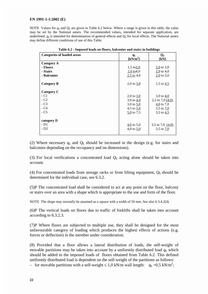
6.3.1.2 Values of actions
(1)P The categories of loaded areas, as specified in Table 6.1, shall be designed by usingcharacteristic values qk (uniformly distributed load) and Qk (concentrated load).
EN 1991-1-1:2002 (E)
22
NOTE Values for qk and Qk are given in Table 6.2 below. Where a range is given in this table, the valuemay be set by the National annex. The recommended values, intended for separate application, areunderlined. qk is intended for determination of general effects and Qk for local effects. The National annexmay define different conditions of use of this Table.
Table 6.2 - Imposed loads on floors, balconies and stairs in buildings
Categories of loaded areas qk
[kN/m2]Qk
[kN]Category A- Floors- Stairs- Balconies
Category B
Category C- C1- C2- C3- C4- C5
category D- D1- D2
1,5 to2,02,0 to4,02,5 to 4,0
2,0 to 3,0
2,0 to 3,03,0 to 4,03,0 to 5,04,5 to 5,05,0 to 7,5
4,0 to 5,04,0 to 5,0
2,0 to 3,02,0 to 4,02,0 to 3,0
1,5 to 4,5
3,0 to 4,02,5 to 7,0 (4,0)
4,0 to 7,03,5 to 7,03,5 to 4,5
3,5 to 7,0 (4,0)3,5 to 7,0
(2) Where necessary qk and Qk should be increased in the design (e.g. for stairs andbalconies depending on the occupancy and on dimensions).
(3) For local verifications a concentrated load Qk acting alone should be taken intoaccount.
(4) For concentrated loads from storage racks or from lifting equipment, Qk should bedetermined for the individual case, see 6.3.2.
(5)P The concentrated load shall be considered to act at any point on the floor, balconyor stairs over an area with a shape which is appropriate to the use and form of the floor.
NOTE The shape may normally be assumed as a square with a width of 50 mm. See also 6.3.4.2(4)
(6)P The vertical loads on floors due to traffic of forklifts shall be taken into accountaccording to 6.3.2.3.
(7)P Where floors are subjected to multiple use, they shall be designed for the mostunfavourable category of loading which produces the highest effects of actions (e.g.forces or deflection) in the member under consideration.
(8) Provided that a floor allows a lateral distribution of loads, the self-weight ofmovable partitions may be taken into account by a uniformly distributed load qk whichshould be added to the imposed loads of floors obtained from Table 6.2. This defineduniformly distributed load is dependent on the self-weight of the partitions as follows:– for movable partitions with a self-weight 1,0 kN/m wall length: qk =0,5 kN/m2;
EN 1991-1-1:2002 (E)
23
– for movable partitions with a self-weight 2,0 kN/m wall length: qk =0,8 kN/m2;– for movable partitions with a self-weight 3,0 kN/m wall length: qk =1,2 kN/m2.
(9) Heavier partitions should be considered in the design taking account of:– the locations and directions of the partitions;– the structural form of the floors.
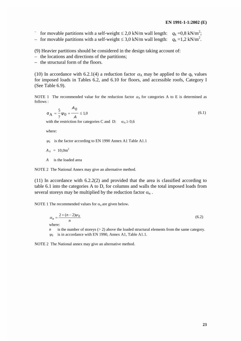
(10) In accordance with 6.2.1(4) a reduction factor A may be applied to the qk valuesfor imposed loads in Tables 6.2, and 6.10 for floors, and accessible roofs, Category I(See Table 6.9).
NOTE 1 The recommended value for the reduction factor A for categories A to E is determined asfollows :
0,10
07
5A
A
A (6.1)
with the restriction for categories C and D: A 0,6
where:
0 is the factor according to EN 1990 Annex A1 Table A1.1
A 0 = 10,0m2
A is the loaded area
NOTE 2 The National Annex may give an alternative method.
(11) In accordance with 6.2.2(2) and provided that the area is classified according totable 6.1 into the categories A to D, for columns and walls the total imposed loads fromseveral storeys may be multiplied by the reduction factor n .
NOTE 1 The recommended values for n are given below.
n
nn
0)2(2
(6.2)
where:n is the number of storeys (> 2) above the loaded structural elements from the same category.0 is in accordance with EN 1990, Annex A1, Table A1.1.
NOTE 2 The National annex may give an alternative method.
EN 1991-1-1:2002 (E)
24
6.3.2 Areas for storage and industrial activities
6.3.2.1 Categories
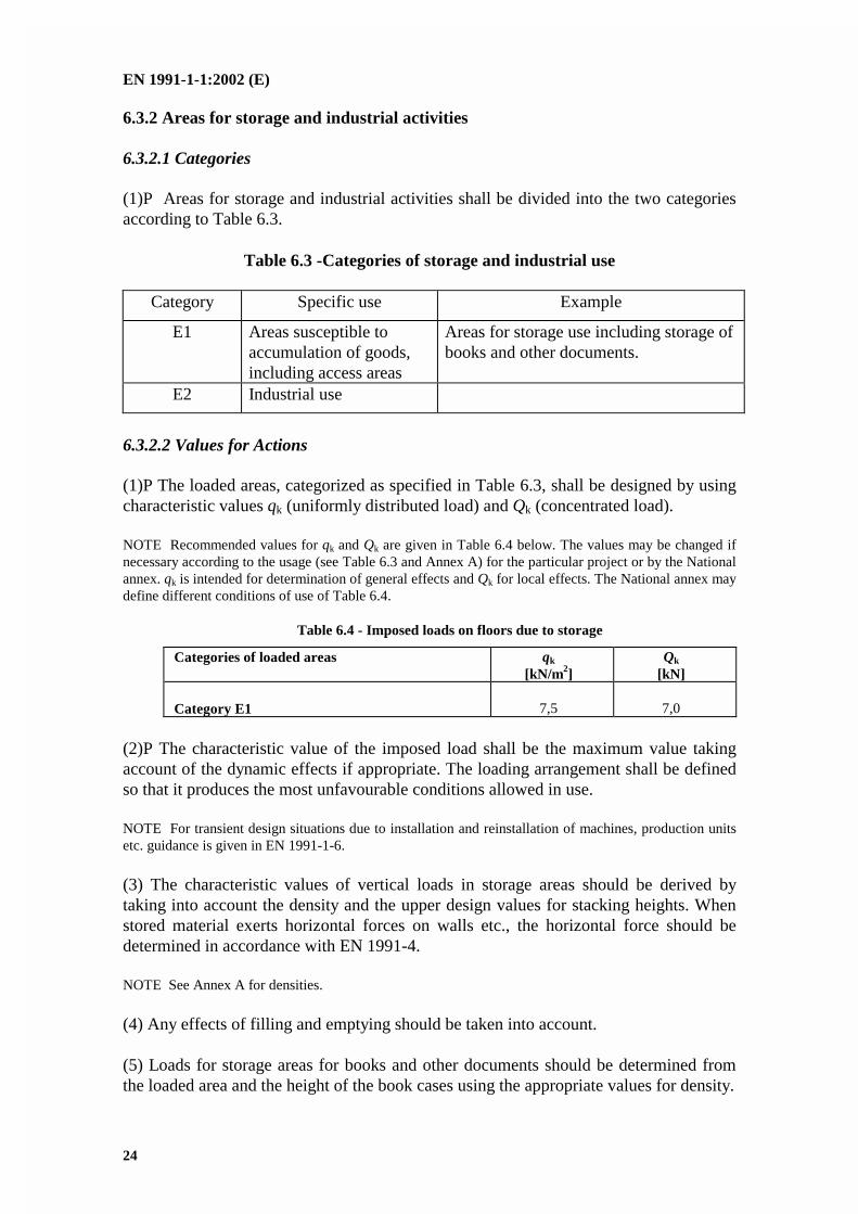
(1)P Areas for storage and industrial activities shall be divided into the two categoriesaccording to Table 6.3.
Table 6.3 -Categories of storage and industrial use
Category Specific use Example
E1 Areas susceptible toaccumulation of goods,including access areas
Areas for storage use including storage ofbooks and other documents.
E2 Industrial use
6.3.2.2 Values for Actions
(1)P The loaded areas, categorized as specified in Table 6.3, shall be designed by usingcharacteristic values qk (uniformly distributed load) and Qk (concentrated load).
NOTE Recommended values for qk and Qk are given in Table 6.4 below. The values may be changed ifnecessary according to the usage (see Table 6.3 and Annex A) for the particular project or by the Nationalannex. qk is intended for determination of general effects and Qk for local effects. The National annex maydefine different conditions of use of Table 6.4.
Table 6.4 - Imposed loads on floors due to storage
Categories of loaded areas qk
[kN/m2]Qk
[kN]
Category E1 7,5 7,0
(2)P The characteristic value of the imposed load shall be the maximum value takingaccount of the dynamic effects if appropriate. The loading arrangement shall be definedso that it produces the most unfavourable conditions allowed in use.
NOTE For transient design situations due to installation and reinstallation of machines, production unitsetc. guidance is given in EN 1991-1-6.
(3) The characteristic values of vertical loads in storage areas should be derived bytaking into account the density and the upper design values for stacking heights. Whenstored material exerts horizontal forces on walls etc., the horizontal force should bedetermined in accordance with EN 1991-4.
NOTE See Annex A for densities.
(4) Any effects of filling and emptying should be taken into account.
(5) Loads for storage areas for books and other documents should be determined fromthe loaded area and the height of the book cases using the appropriate values for density.
EN 1991-1-1:2002 (E)
25
(6) Loads in industrial areas should be assessed considering the intended use and theequipment which is to be installed. Where equipment such as cranes, movingmachinery etc, are to be installed the effects on the structure should be determined inaccordance with EN 1991-3.
(7) Actions due to forklifts and transport vehicles should be considered as concentratedloads acting together with the appropriate imposed distributed loads given in Tables 6.2,6.4. and 6.8.
6.3.2.3 Actions induced by forklifts
(1) Forklifts should be classified in 6 classes FL 1 to FL 6 depending on net weight,dimensions and hoisting loads, see Table 6.5.
Table 6.5 - Dimensions of forklift according to classes FL
Class ofForklift
Netweight[kN]
Hoistingload[kN]
Width ofaxlea [m]
Overallwidthb [m]
Overalllengthl [m]
FL 1FL 2FL 3FL 4FL 5FL 6
2131446090110
101525406080
0,850,951,001,201,501,80
1,001,101,201,401,902,30
2,603,003,304,004,605,10
(2) The static vertical axle load Qk of a forklift depends on the forklift classes FL1 toFL6 and should be obtained from Table 6.6.
Table 6.6 - Axle loads of forklifts
Class of forklifts Axle load Qk
[kN]FL 1FL 2FL 3FL 4FL 5FL 6
26406390140170
(3) The static vertical axle load Qk should be increased by the dynamic factor usingexpression (6.3).
Qk,dyn = Qk (6.3)
whre:Qk,dyn is the dynamic characteristic value of the action;
EN 1991-1-1:2002 (E)
26
is the dynamic magnification factor;Qk is the static characteristic value of the action.
(4) The dynamic factor for forklifts takes into account the inertial effects caused byacceleration and deceleration of the hoisting load and should be taken as: = 1,40 for pneumatic tyres, = 2,00 for solid tyres.
(5) For forklifts having a net weight greater than 110 kN the loads should be defined bya more accurate analysis.
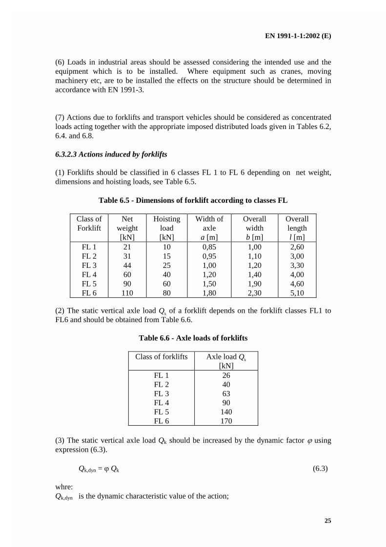
(6) The vertical axle load Qk and Qk,dyn of a forklift should be arranged according toFigure 6.1.
Figure 6.1 - Dimensions of forklifts
(7) Horizontal loads due to acceleration or deceleration of forklifts may be taken as30 % of the vertical axle loads Qk.
NOTE Dynamic factors need not be applied.
6.3.2.4 Actions induced by transport vehicles
(1) The actions from transport vehicles that move on floors freely or guided by railsshould be determined by a pattern of wheel loads.
(2) The static values of the vertical wheel loads should be given in terms of permanentweights and pay loads. Their spectra should be used to define combination factors andfatigue loads.
(3) The vertical and horizontal wheel loads should be determined for the specific case.
(4) The load arrangement including the dimensions relevant for the design should bedetermined for the specific case.

EN 1991-1-1:2002 (E)
27
NOTE Appropriate load models from EN 1991-2 may be used where relevant.
6.3.2.5 Actions induced by special devices for maintenance
(1) Special devices for maintenance should be modelled as loads from transportationvehicles, see 6.3.2.4.
(2) The load arrangements including the dimensions relevant for the design should bedetermined for the specific case.
6.3.3 Garages and vehicle traffic areas (excluding bridges)
6.3.3.1 Categories
(1)P Traffic and parking areas in buildings shall be divided into two categoriesaccording to their accessibility for vehicles as shown in Table 6.7.
Table 6.7 - Traffic and parking areas in buildings
Categories of traffic areas Specific Use Examples
F Traffic and parking areas forlight vehicles ( 30 kN grossvehicle weight and 8 seatsnot including driver)
garages;parking areas, parking halls
G Traffic and parking areas formedium vehicles (>30 kN, 160 kN gross vehicle weight,on 2 axles)
access routes; deliveryzones; zones accessible tofire engines ( 160 kN grossvehicle weight)
NOTE 1 Access to areas designed to category F should be limited by physical means built into the structure.
NOTE 2 Areas designed to categories F and G should be posted with the appropriate warning signs.
6.3.3.2 Values of actions
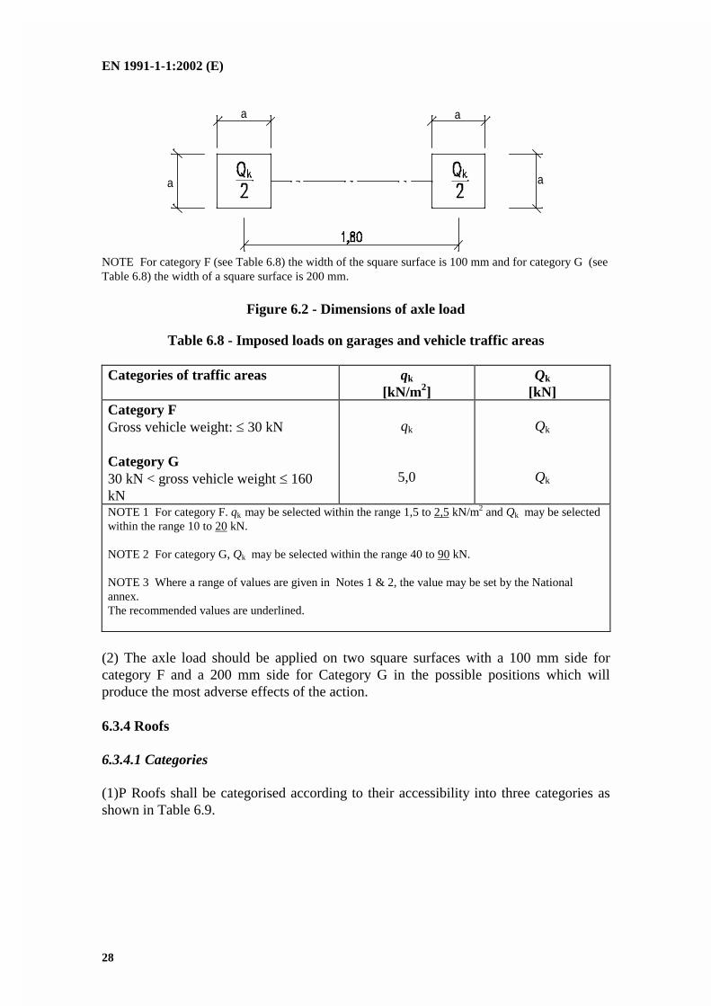
(1) The load model which should be used is a single axle with a load Qk withdimensions according to Figure 6.2 and a uniformly distributed load qk. Thecharacteristic values for qk and Qk are given in Table 6.8.
NOTE qk is intended for determination of general effects and Qk for local effects. The National annexmay define different conditions of use of this Table.
EN 1991-1-1:2002 (E)
28
a
a
a
a
NOTE For category F (see Table 6.8) the width of the square surface is 100 mm and for category G (seeTable 6.8) the width of a square surface is 200 mm.
Figure 6.2 - Dimensions of axle load
Table 6.8 - Imposed loads on garages and vehicle traffic areas
Categories of traffic areas qk
[kN/m2]Qk
[kN]Category FGross vehicle weight: 30 kN
Category G30 kN < gross vehicle weight 160kN
qk
5,0
Qk
Qk
NOTE 1 For category F. qk may be selected within the range 1,5 to 2,5 kN/m2 and Qk may be selectedwithin the range 10 to 20 kN.
NOTE 2 For category G, Qk may be selected within the range 40 to 90 kN.
NOTE 3 Where a range of values are given in Notes 1 & 2, the value may be set by the Nationalannex.The recommended values are underlined.
(2) The axle load should be applied on two square surfaces with a 100 mm side forcategory F and a 200 mm side for Category G in the possible positions which willproduce the most adverse effects of the action.
6.3.4 Roofs
6.3.4.1 Categories
(1)P Roofs shall be categorised according to their accessibility into three categories asshown in Table 6.9.
EN 1991-1-1:2002 (E)
29
Table 6.9 - Categorization of roofs
Categories ofloaded area
Specific Use
H Roofs not accessible except for normal maintenance andrepair.
I Roofs accessible with occupancy according to categories A toD
K Roofs accessible for special services, such as helicopterlanding areas
(2) Imposed loads for roofs of category H should be those given in Table 6.10. Imposedloads for roofs of category I are given in Tables 6.2, 6.4 and 6.8 according to the specificuse.
(3) The loads for roofs of category K which provide areas for helicopter landing areasshould be for the helicopter classes HC, see Table 6.11.
6.3.4.2 Values of actions
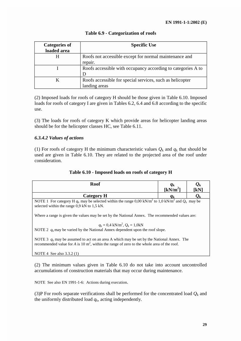
(1) For roofs of category H the minimum characteristic values Qk and qk that should beused are given in Table 6.10. They are related to the projected area of the roof underconsideration.
Table 6.10 - Imposed loads on roofs of category H
Roof qk
[kN/m2]Qk
[kN]Category H qk Qk
NOTE 1 For category H qk may be selected within the range 0,00 kN/m2 to 1,0 kN/m2 and Qk may beselected within the range 0,9 kN to 1,5 kN.
Where a range is given the values may be set by the National Annex. The recommended values are:
qk = 0,4 kN/m2, Qk = 1,0kNNOTE 2 qk may be varied by the National Annex dependent upon the roof slope.
NOTE 3 qk may be assumed to act on an area A which may be set by the National Annex. Therecommended value for A is 10 m2, within the range of zero to the whole area of the roof.
NOTE 4 See also 3.3.2 (1)
(2) The minimum values given in Table 6.10 do not take into account uncontrolledaccumulations of construction materials that may occur during maintenance.
NOTE See also EN 1991-1-6: Actions during execution.
(3)P For roofs separate verifications shall be performed for the concentrated load Qk andthe uniformly distributed load qk, acting independently.
EN 1991-1-1:2002 (E)
30
(4) Roofs, other than those with roof sheeting, should be designed to resist 1,5 kN on anarea based on a 50 mm sided square. Roof elements with a profiled or discontinuouslylaid surface, should be designed so that the concentrated load Qk acts over the effectivearea provided by load spreading arrangements.
(5) For roofs of category K the actions from helicopters on landing areas should bedetermined in accordance with Table 6.11, and using the dynamic factors given in6.3.4.2 (6) and expression 6.3
Table 6.11 - Imposed loads on roofs of category K for helicopters
Class ofHelicopter
Take-off load Qof helicopter
Take-off load Qk Dimension ofthe loaded area
(m x m)HC1HC2
Q 20 kN 20 kN< Q 60 kN
Qk = 20 kNQk = 60 kN
0,2 x 0,20,3 x 0,3
(6) The dynamic factor to be applied to the take off load Qk to take account of impacteffects may be taken as = 1,40.
(7) Access ladders and walkways should be assumed to be loaded according to Table6.10 for a roof slope < 20°. For walkways which are part of a designated escape route,qk should be according to Table 6.2. For walkways for service a minimum characteristicvalue Qk of 1,5 kN should be taken.
(8) The following loads should be used for the design of frames and coverings of accesshatches (other than glazing), the supports of ceilings and similar structures :a) without access: no imposed load;b) with access: 0,25 kN/m2 distributed over the whole area or the area supported,
and the concentrated load of 0,9 kN so placed so as to produce maximumstresses in the affected member.
6.4 Horizontal loads on parapets and partition walls acting as barriers
(1) The characteristic values of the line load qk acting at the height of the partition wallor parapets but not higher than 1,20 m should be taken from Table 6.12.
EN 1991-1-1:2002 (E)
31
Table 6.12 - Horizontal loads on partition walls and parapets
Loaded areas qk
[kN/m]Category A
Category B and C1
Categories C2 –to C4 and D
Category C5
Category E
Category F
Category G
qk
qk
qk
qk
qk
See Annex B
See Annex B
NOTE 1 For categories A, B and C1, qk may be selected within the range 0,2 to 1,0(0,5).NOTE 2 For categories C2 to C4 and D qk may be selected within the range 0,8kN/m –to 1,0 kN/m.NOTE 3 For category C5 qk may be selected within the range 3,0 kN/m to 5,0kN/m.NOTE 4 For category E qk may be selected within the range 0,8 kN/m to 2,0kN/m. For areas of category E the horizontal loads depend on the occupancy.Therefore the value of qk is defined as a minimum value and should be checked for thespecific occupancy.NOTE 5 Where a range of values is given in Notes 1, 2, 3 and 4, the value may be setby the National Annex. The recommended value is underlined.NOTE 6 The National Annex may prescribe additional point loads Qk and/or hard orsoft body impact specifications for analytical or experimental verification.
(2) For areas susceptible to significant overcrowding associated with public events e.g.for sports stadia, stands, stages, assembly halls or conference rooms, the line loadshould be taken according to category C5.
EN 1991-1-1:2002 (E)
32
Annex A(informative)
Tables for nominal density of construction materials, and nominaldensity and angles of repose for stored materials
Table A.1 - Construction materials-concrete and mortar
Materials Density
[kN/m3]concrete (see EN 206)lightweightdensity class LC 1,0density class LC 1,2density class LC 1,4density class LC 1,6density class LC 1,8density class LC 2,0normal weightheavy weight
mortarcement mortargypsum mortarlime-cement mortarlime mortar
9,0 to 10,0 1)2)
10,0 to 12,0 1)2)
12,0 to 14,0 1)2)
14,0 to 16,0 1)2)
16,0 to 18,0 1)2)
18,0 to 20,0 1)2)
24,01)2)
>1)2)
19,0 to 23,012,0 to 18,018,0 to 20,012,0 to 18,0
1) Increase by 1kN/m3 for normal percentage of reinforcing and pre-stressing steel2)
Increase by 1kN/m3 for unhardened concreteNOTE See Section 4
EN 1991-1-1:2002 (E)
33
Table A.2 - Construction materials-masonry
Materials Density
[kN/m3]masonry unitsclay masonry unitscalcium silicate masonry units
aggregate concrete masonry units
autoclaved aerated masonry units
manufactured stone masonry units
glass blocks, hollow
terra cotta
natural stones, see prEN 771-6 granite, syenite, porphyry basalt, diorite, gabbro tachylyte basaltic lava gray wacke, sandstone dense limestone other limestone volcanic tuff gneiss slate
see prEN 771-1see prEN 771-2
see prEN 771-3
see prEN 771-4
see prEN 771-5
see prEN 1051
21,0
27,0 to 30,027,0 to 31,0
26,024,0
21,0 to 27,020,0 to 29,0
20,020,030,028,0
NOTE See Section 4.
EN 1991-1-1:2002 (E)
34
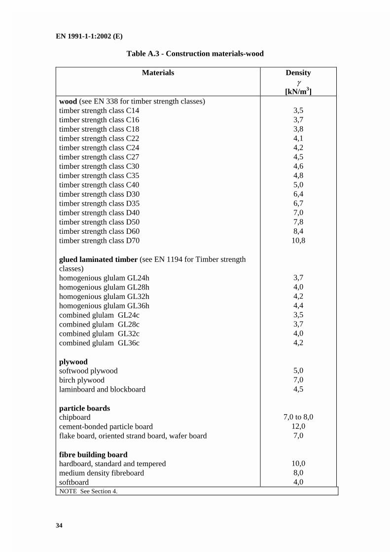
Table A.3 - Construction materials-wood
Materials Density
[kN/m3]wood (see EN 338 for timber strength classes)timber strength class C14timber strength class C16timber strength class C18timber strength class C22timber strength class C24timber strength class C27timber strength class C30timber strength class C35timber strength class C40timber strength class D30timber strength class D35timber strength class D40timber strength class D50timber strength class D60timber strength class D70
glued laminated timber (see EN 1194 for Timber strengthclasses)homogenious glulam GL24hhomogenious glulam GL28hhomogenious glulam GL32hhomogenious glulam GL36hcombined glulam GL24ccombined glulam GL28ccombined glulam GL32ccombined glulam GL36c
plywoodsoftwood plywoodbirch plywoodlaminboard and blockboard
particle boardschipboardcement-bonded particle boardflake board, oriented strand board, wafer board
fibre building boardhardboard, standard and temperedmedium density fibreboardsoftboard
3,53,73,84,14,24,54,64,85,06,46,77,07,88,410,8
3,74,04,24,43,53,74,04,2
5,07,04,5
7,0 to 8,012,07,0
10,08,04,0
NOTE See Section 4.

EN 1991-1-1:2002 (E)
35
Table A.4 - Construction materials-metals
Materials Density
[kN/m3]metalsaluminiumbrassbronzecopperiron, castiron, wroughtleadsteelzinc
27,083,0 to 85,083,0 to 85,087,0 to 89,071,0 to 72,5
76,0112,0 to 114,077,0 to 78,571,0 to 72,0
Table A.5 - Construction materials- other materials
Materials Density
[kN/m3]other materials
glass, brokenglass, in sheetsplasticsacrylic sheetpolystyrene, expanded, granulesfoam glassslate
22,025,0
12,00,31,428,0

EN 1991-1-1:2002 (E)
36
Table A.6 - Bridge materials
Materials Density
[kN/m3]pavement of road bridgesgussasphalt and asphaltic concretemastic asphalthot rolled asphalt
infills for bridgessand (dry)ballast, gravel (loose)hardcorecrushed slagpacked stone rubblepuddle clay
pavement of rail bridgesconcrete protective layernormal ballast (e.g. granite, gneiss, etc.)basaltic ballast
24,0 to 25,018,0 to 22,0
23,0
15,0 to 16,01)
15,0 to 16,01)
18,5 to 19,513,5 to 14,51)
20,5 to 21,518,5 to 19,5
25,020,026
Weight per unit bedlength 2) 3)
gk
[kN/m]structures with ballasted bed2 rails UIC 60prestressed concrete sleeper with track fasteningsconcrete sleepers with metal angle bracestimber sleepers with track fastenings
1,24,8-
1,9
structures without ballasted bed2 rails UIC 60 with track fastenings2 rails UIC 60 with track fastenings, bridge beam and guard rails
1,7
4,91) Given in other tables as stored materials2) Excludes an allowance for ballast3) Assumes a spacing of 600mm
NOTE 1 The values for track are also applicable outside railway bridges.NOTE 2 See Section 4.
EN 1991-1-1:2002 (E)
37
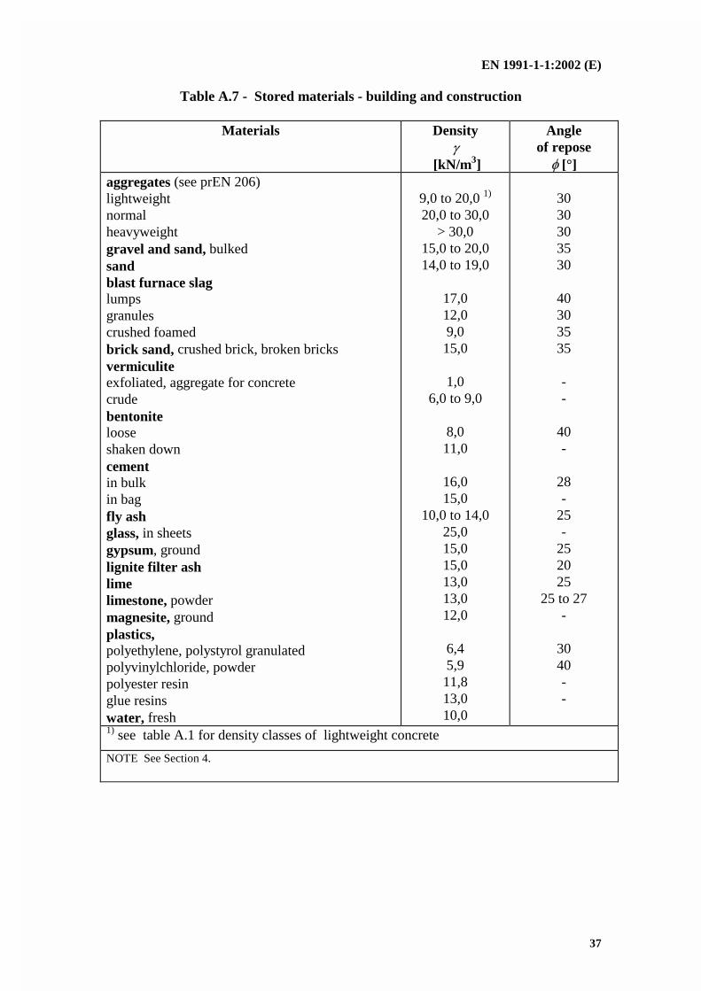
Table A.7 - Stored materials - building and construction
Materials Density
[kN/m3]
Angleof repose
[°]aggregates (see prEN 206)lightweightnormalheavyweightgravel and sand, bulkedsandblast furnace slaglumpsgranulescrushed foamedbrick sand, crushed brick, broken bricksvermiculiteexfoliated, aggregate for concretecrudebentonitelooseshaken downcementin bulkin bagfly ashglass, in sheetsgypsum, groundlignite filter ashlimelimestone, powdermagnesite, groundplastics,polyethylene, polystyrol granulatedpolyvinylchloride, powderpolyester resinglue resinswater, fresh
9,0 to 20,0 1)
20,0 to 30,0> 30,0
15,0 to 20,014,0 to 19,0
17,012,09,015,0
1,06,0 to 9,0
8,011,0
16,015,0
10,0 to 14,025,015,015,013,013,012,0
6,45,911,813,010,0
3030303530
40303535
--
40-
28-
25-
252025
25 to 27-
3040--
1) see table A.1 for density classes of lightweight concrete
NOTE See Section 4.
EN 1991-1-1:2002 (E)
38
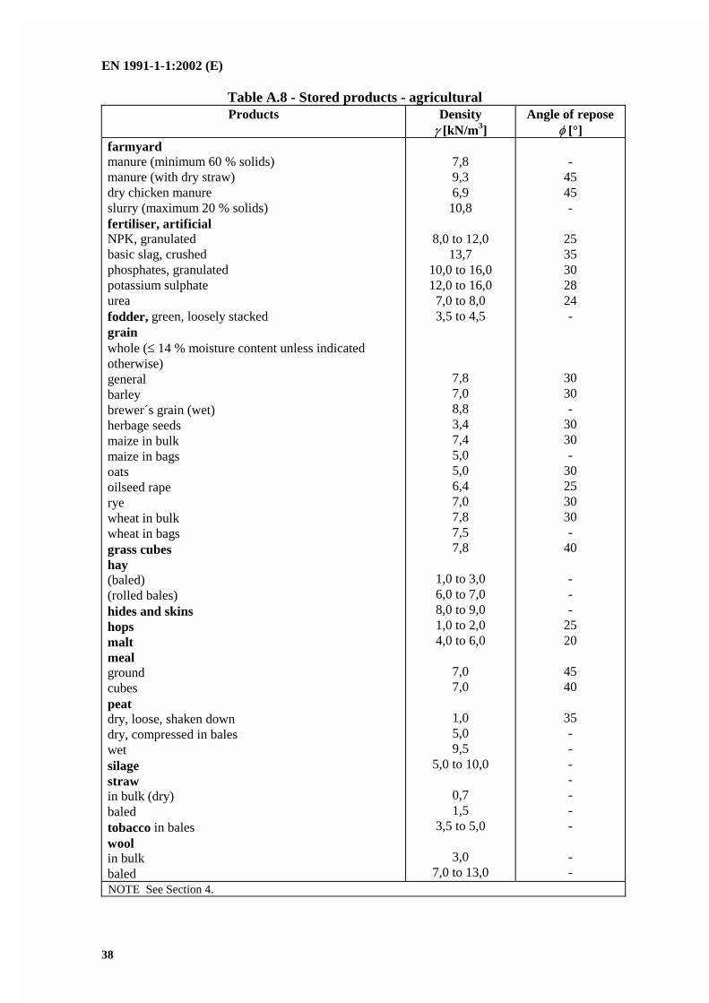
Table A.8 - Stored products - agriculturalProducts Density
[kN/m3]Angle of repose
[°]farmyardmanure (minimum 60 % solids)manure (with dry straw)dry chicken manureslurry (maximum 20 % solids)fertiliser, artificialNPK, granulatedbasic slag, crushedphosphates, granulatedpotassium sulphateureafodder, green, loosely stackedgrainwhole ( 14 % moisture content unless indicatedotherwise)generalbarleybrewer´s grain (wet)herbage seedsmaize in bulkmaize in bagsoatsoilseed raperyewheat in bulkwheat in bagsgrass cubeshay(baled)(rolled bales)hides and skinshopsmaltmealgroundcubespeatdry, loose, shaken downdry, compressed in baleswetsilagestrawin bulk (dry)baledtobacco in baleswoolin bulkbaled
7,89,36,910,8
8,0 to 12,013,7
10,0 to 16,012,0 to 16,07,0 to 8,03,5 to 4,5
7,87,08,83,47,45,05,06,47,07,87,57,8
1,0 to 3,06,0 to 7,08,0 to 9,01,0 to 2,04,0 to 6,0
7,07,0
1,05,09,5
5,0 to 10,0
0,71,5
3,5 to 5,0
3,07,0 to 13,0
-4545-
2535302824-
3030-
3030-
30253030-
40
---
2520
4540
35-------
--
NOTE See Section 4.
EN 1991-1-1:2002 (E)
39
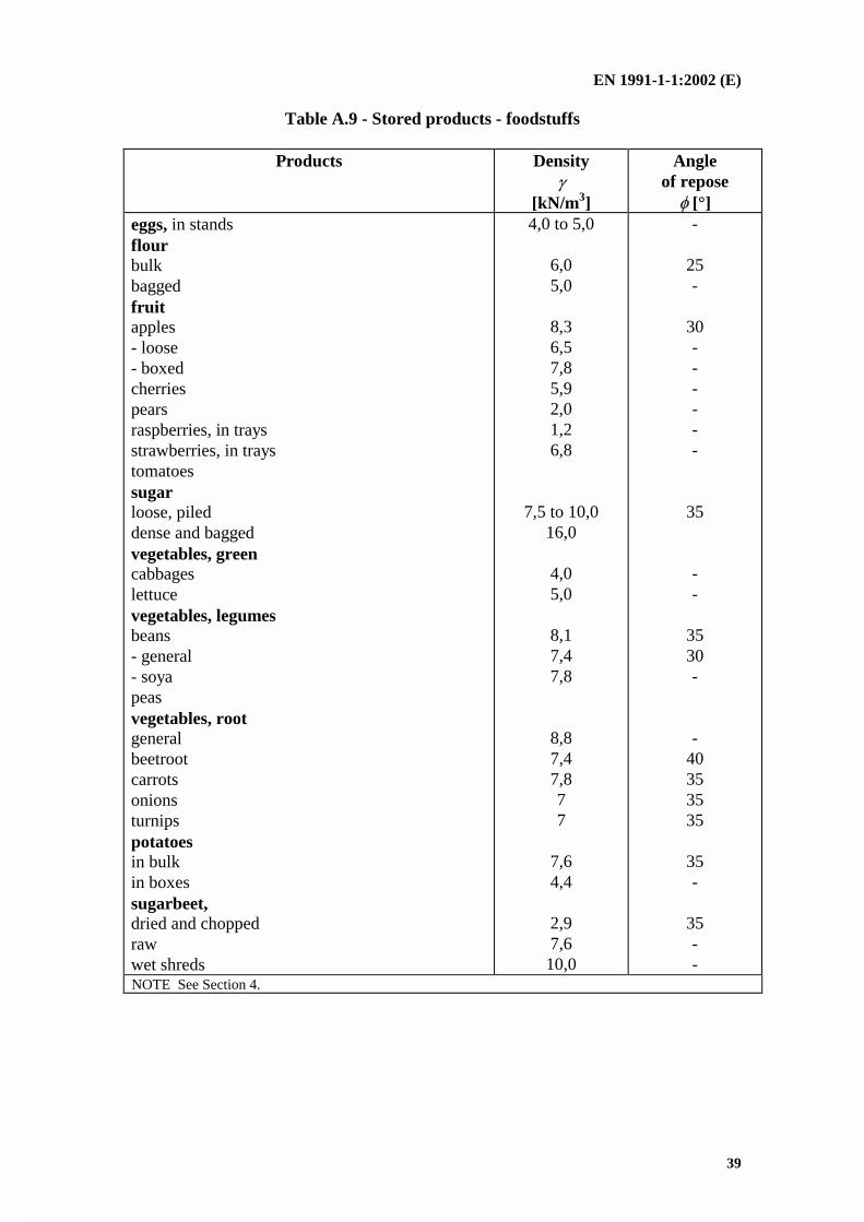
Table A.9 - Stored products - foodstuffs
Products Density
[kN/m3]
Angleof repose
[°]eggs, in standsflourbulkbaggedfruitapples- loose- boxedcherriespearsraspberries, in traysstrawberries, in traystomatoessugarloose, pileddense and baggedvegetables, greencabbageslettucevegetables, legumesbeans- general- soyapeasvegetables, rootgeneralbeetrootcarrotsonionsturnipspotatoesin bulkin boxessugarbeet,dried and choppedrawwet shreds
4,0 to 5,0
6,05,0
8,36,57,85,92,01,26,8
7,5 to 10,016,0
4,05,0
8,17,47,8
8,87,47,877
7,64,4
2,97,610,0
-
25-
30------
35
--
3530-
-40353535
35-
35--
NOTE See Section 4.
EN 1991-1-1:2002 (E)
40
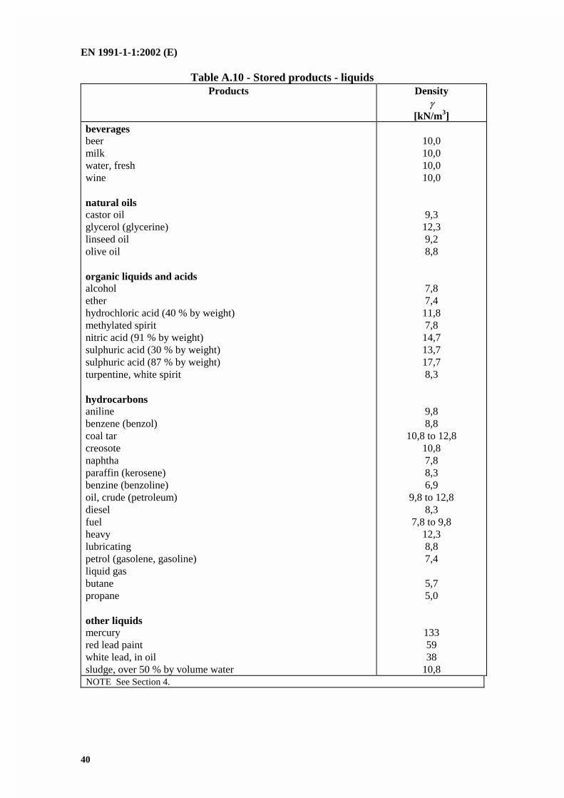
Table A.10 - Stored products - liquidsProducts Density
[kN/m 3]beveragesbeermilkwater, freshwine
natural oilscastor oilglycerol (glycerine)linseed oilolive oil
organic liquids and acidsalcoholetherhydrochloric acid (40 % by weight)methylated spiritnitric acid (91 % by weight)sulphuric acid (30 % by weight)sulphuric acid (87 % by weight)turpentine, white spirit
hydrocarbonsanilinebenzene (benzol)coal tarcreosotenaphthaparaffin (kerosene)benzine (benzoline)oil, crude (petroleum)dieselfuelheavylubricatingpetrol (gasolene, gasoline)liquid gasbutanepropane
other liquidsmercuryred lead paintwhite lead, in oilsludge, over 50 % by volume water
10,010,010,010,0
9,312,39,28,8
7,87,411,87,814,713,717,78,3
9,88,8
10,8 to 12,810,87,88,36,9
9,8 to 12,88,3
7,8 to 9,812,38,87,4
5,75,0
1335938
10,8NOTE See Section 4.
EN 1991-1-1:2002 (E)
41
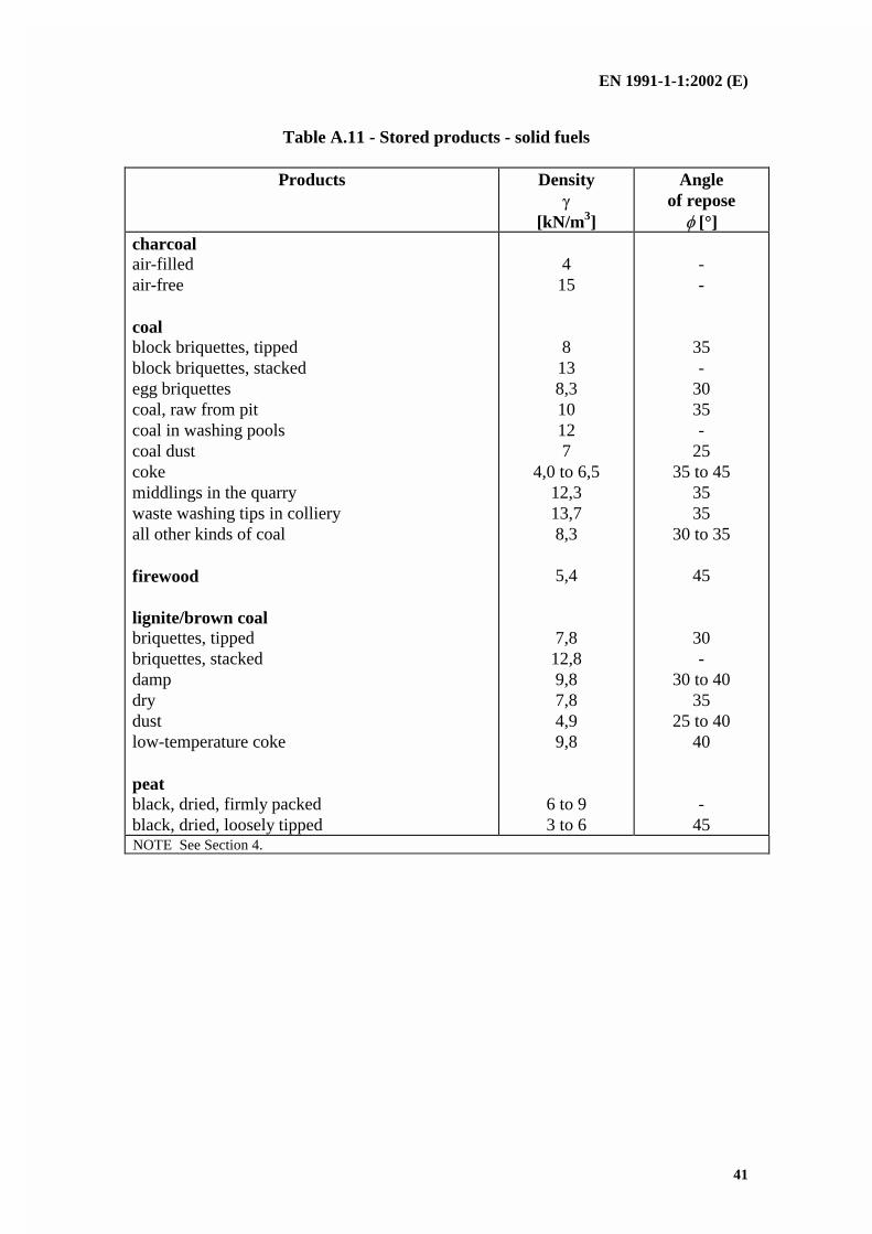
Table A.11 - Stored products - solid fuels
Products Density
[kN/m3]
Angleof repose
[°]charcoalair-filledair-free
coalblock briquettes, tippedblock briquettes, stackedegg briquettescoal, raw from pitcoal in washing poolscoal dustcokemiddlings in the quarrywaste washing tips in collieryall other kinds of coal
firewood
lignite/brown coalbriquettes, tippedbriquettes, stackeddampdrydustlow-temperature coke
peatblack, dried, firmly packedblack, dried, loosely tipped
415
8138,310127
4,0 to 6,512,313,78,3
5,4
7,812,89,87,84,99,8
6 to 93 to 6
--
35-
3035-
2535 to 45
3535
30 to 35
45
30-
30 to 4035
25 to 4040
-45
NOTE See Section 4.
EN 1991-1-1:2002 (E)
42
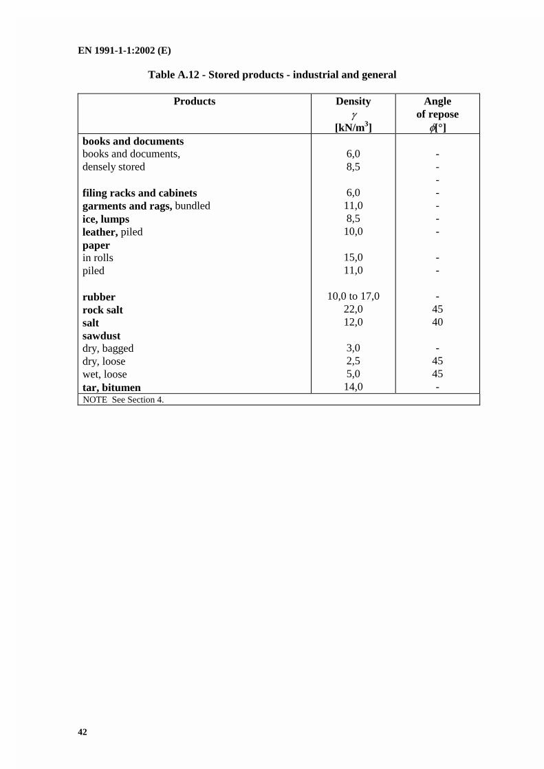
Table A.12 - Stored products - industrial and general
Products Density
[kN/m3]
Angleof repose
[°]books and documentsbooks and documents,densely stored
filing racks and cabinetsgarments and rags, bundledice, lumpsleather, piledpaperin rollspiled
rubberrock saltsaltsawdustdry, baggeddry, loosewet, loosetar, bitumen
6,08,5
6,011,08,510,0
15,011,0
10,0 to 17,022,012,0
3,02,55,014,0
-------
--
-4540
-4545-
NOTE See Section 4.
EN 1991-1-1:2002 (E)
43
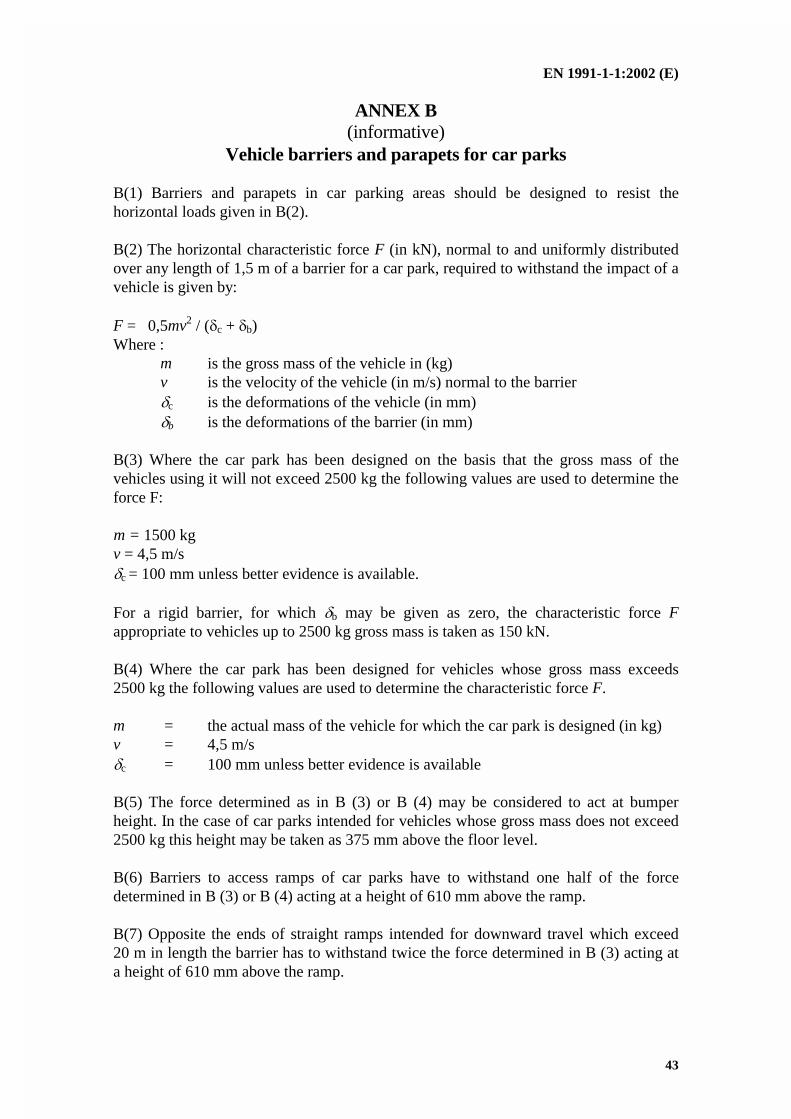
ANNEX B(informative)
Vehicle barriers and parapets for car parks
B(1) Barriers and parapets in car parking areas should be designed to resist thehorizontal loads given in B(2).
B(2) The horizontal characteristic force F (in kN), normal to and uniformly distributedover any length of 1,5 m of a barrier for a car park, required to withstand the impact of avehicle is given by:
F = 0,5mv2 / (c + b)Where :
m is the gross mass of the vehicle in (kg)v is the velocity of the vehicle (in m/s) normal to the barrierc is the deformations of the vehicle (in mm)b is the deformations of the barrier (in mm)
B(3) Where the car park has been designed on the basis that the gross mass of thevehicles using it will not exceed 2500 kg the following values are used to determine theforce F:
m = 1500 kgv = 4,5 m/sc = 100 mm unless better evidence is available.
For a rigid barrier, for which b may be given as zero, the characteristic force Fappropriate to vehicles up to 2500 kg gross mass is taken as 150 kN.
B(4) Where the car park has been designed for vehicles whose gross mass exceeds2500 kg the following values are used to determine the characteristic force F.
m = the actual mass of the vehicle for which the car park is designed (in kg)v = 4,5 m/sc = 100 mm unless better evidence is available
B(5) The force determined as in B (3) or B (4) may be considered to act at bumperheight. In the case of car parks intended for vehicles whose gross mass does not exceed2500 kg this height may be taken as 375 mm above the floor level.
B(6) Barriers to access ramps of car parks have to withstand one half of the forcedetermined in B (3) or B (4) acting at a height of 610 mm above the ramp.
B(7) Opposite the ends of straight ramps intended for downward travel which exceed20 m in length the barrier has to withstand twice the force determined in B (3) acting ata height of 610 mm above the ramp.

EN 1991-1-1:2002 (E)
44
Bibliography
ISO 2394 General principles on reliability for structures
ISO 3898 Basis of design of structures - Notations. General symbols
ISO 8930 General principles on reliability for structures. List of equivalent terms
EUROPEAN STANDARD
NORME EUROPÉENNE
EUROPÄISCHE NORM
EN 1991-1-2
November 2002
ICS 13.220.50; 91.010.30 Supersedes ENV 1991-2-2:1995
English version
Eurocode 1: Actions on structures - Part 1-2: General actions -Actions on structures exposed to fire
Eurocode 1: Actions sur les structures au feu - Partie 1-2:Actions générales - Actions sur les structures exposées
Eurocode 1 - Einwirkungen auf Tragwerke - Teil 1-2:Allgemeine Einwirkungen - Brandeinwirkungen auf
Tragwerke
This European Standard was approved by CEN on 1 September 2002.
CEN members are bound to comply with the CEN/CENELEC Internal Regulations which stipulate the conditions for giving this EuropeanStandard the status of a national standard without any alteration. Up-to-date lists and bibliographical references concerning such nationalstandards may be obtained on application to the Management Centre or to any CEN member.
This European Standard exists in three official versions (English, French, German). A version in any other language made by translationunder the responsibility of a CEN member into its own language and notified to the Management Centre has the same status as the officialversions.
CEN members are the national standards bodies of Austria, Belgium, Czech Republic, Denmark, Finland, France, Germany, Greece,Iceland, Ireland, Italy, Luxembourg, Malta, Netherlands, Norway, Portugal, Spain, Sweden, Switzerland and United Kingdom.
EUROPEAN COMMITTEE FOR STANDARDIZATIONC OM ITÉ EUR OP ÉEN DE NOR M ALIS AT IONEUROPÄISCHES KOMITEE FÜR NORMUNG
Management Centre: rue de Stassart, 36 B-1050 Brussels
© 2002 CEN All rights of exploitation in any form and by any means reservedworldwide for CEN national Members.
Ref. No. EN 1991-1-2:2002 E
EN 1991-1-2:2002 (E)
2
Contents page
Foreword ....................................................................................................................... .....4
Section 1 General .............................................................................................................10
1.1 Scope .......................................................................................................................................... 101.2 Normative references.................................................................................................................. 101.3 Assumptions................................................................................................................................ 111.4 Distinction between Principles and Application Rules ................................................................. 111.5 Terms and definitions.................................................................................................................. 11
1.5.1 Common terms used in Eurocode Fire parts ................................................................. 111.5.2 Special terms relating to design in general..................................................................... 131.5.3 Terms relating to thermal actions ................................................................................... 131.5.4 Terms relating to heat transfer analysis ......................................................................... 15
1.6 Symbols....................................................................................................................................... 15
Section 2 Structural Fire design procedure....................................................................21
2.1 General........................................................................................................................................ 212.2 Design fire scenario..................................................................................................................... 212.3 Design fire ................................................................................................................................... 212.4 Temperature Analysis ................................................................................................................. 212.5 Mechanical Analysis .................................................................................................................... 22
Section 3 Thermal actions for temperature analysis .....................................................23
3.1 General rules............................................................................................................................... 233.2 Nominal temperature-time curves ............................................................................................... 24
3.2.1 Standard temperature-time curve................................................................................... 243.2.2 External fire curve........................................................................................................... 243.2.3 Hydrocarbon curve ......................................................................................................... 25
3.3 Natural fire models ...................................................................................................................... 253.3.1 Simplified fire models ..................................................................................................... 25
3.3.1.1 General ........................................................................................................... 253.3.1.2 Compartment fires .......................................................................................... 253.3.1.3 Localised fires ................................................................................................. 26
3.3.2 Advanced fire models ..................................................................................................... 26
Section 4 Mechanical actions for structural analysis ....................................................27
4.1 General........................................................................................................................................ 274.2 Simultaneity of actions................................................................................................................. 27
4.2.1 Actions from normal temperature design ....................................................................... 274.2.2 Additional actions............................................................................................................ 28
4.3 Combination rules for actions...................................................................................................... 284.3.1 General rule.................................................................................................................... 284.3.2 Simplified rules ............................................................................................................... 284.3.3 Load level ....................................................................................................................... 29
Annex A (informative) Parametric temperature-time curves..............................................30
Annex B (informative) Thermal actions for external members - Simplified calculationmethod ......................................................................................................................... .33
B.1 Scope .......................................................................................................................................... 33B.2 Conditions of use......................................................................................................................... 33
EN 1991-1-2:2002 (E)
3
B.3 Effects of wind ............................................................................................................................. 34B.3.1 Mode of ventilation.......................................................................................................... 34B.3.2 Flame deflection by wind ................................................................................................ 34
B.4 Characteristics of fire and flames................................................................................................ 35B.4.1 No forced draught........................................................................................................... 35B.4.2 Forced draught ............................................................................................................... 37
B.5 Overall configuration factors........................................................................................................ 39
Annex C (informative) Localised fires..................................................................................41
Annex D (informative) Advanced fire models......................................................................44
D.1 One-zone models ........................................................................................................................ 44D.2 Two-zone models ........................................................................................................................ 45D.3 Computational fluid dynamic models........................................................................................... 45
Annex E (informative) Fire load densities ...........................................................................46
E.1 General........................................................................................................................................ 46E.2 Determination of fire load densities ............................................................................................. 47
E.2.1 General........................................................................................................................... 47E.2.2 Definitions....................................................................................................................... 47E.2.3 Protected fire loads......................................................................................................... 48E.2.4 Net calorific values ......................................................................................................... 48E.2.5 Fire load classification of occupancies ........................................................................... 50E.2.6 Individual assessment of fire load densities ................................................................... 50
E.3 Combustion behaviour ................................................................................................................ 50E.4 Rate of heat release Q ................................................................................................................ 51
Annex F (informative) Equivalent time of fire exposure .....................................................53
Annex G (informative) Configuration factor ........................................................................55
G.1 General........................................................................................................................................ 55G.2 Shadow effects............................................................................................................................ 56G.3 External members ....................................................................................................................... 56
Bibliography ................................................................................................................... .......59

EN 1991-1-2:2002 (E)
4
Foreword
This document (EN 1991-1-2:2002) has been prepared by Technical Committee CEN/TC 250 "StructuralEurocodes", the secretariat of which is held by BSI.
CEN/TC250/SC1 is responsible for Eurocode 1.
This European Standard shall be given the status of a national standard, either by publication of anidentical text or by endorsement, at the latest by May 2003, and conflicting national standards shall bewithdrawn at the latest by December 2009.
This document supersedes ENV 1991-2-2:1995.
Annexes A, B, C, D, E, F and G are informative.
According to the CEN/CENELEC Internal Regulations, the national standards organizations of thefollowing countries are bound to implement this European Standard: Austria, Belgium, Czech Republic,Denmark, Finland, France, Germany, Greece, Iceland, Ireland, Italy, Luxembourg, Malta, Netherlands,Norway, Portugal, Spain, Sweden, Switzerland and the United Kingdom.
Background of the Eurocode programme
In 1975, the Commission of the European Community decided on an action programme in the field ofconstruction, based on article 95 of the Treaty. The objective of the programme was the elimination oftechnical obstacles to trade and the harmonisation of technical specifications.
Within this action programme, the Commission took the initiative to establish a set of harmonisedtechnical rules for the design of construction works which, in a first stage, would serve as an alternative tothe national rules in force in the Member States and, ultimately, would replace them.
For fifteen years, the Commission, with the help of a Steering Committee with Representatives of MemberStates, conducted the development of the Eurocodes programme, which led to the first generation ofEuropean codes in the 1980’s.
In 1989, the Commission and the Member States of the EU and EFTA decided, on the basis of anagreement1 between the Commission and CEN, to transfer the preparation and the publication of theEurocodes to CEN through a series of Mandates, in order to provide them with a future status ofEuropean Standard (EN). This links de facto the Eurocodes with the provisions of all the Council’sDirectives and/or Commission’s Decisions dealing with European Standards (e.g. the Council Directive89/106/EEC on construction products - CPD - and Council Directives 93/37/EEC, 92/50/EEC and89/440/EEC on public works and services and equivalent EFTA Directives initiated in pursuit of setting upthe internal market).
The Structural Eurocode programme comprises the following standards generally consisting of a numberof Parts:
EN 1990, Eurocode: Basis of structural design.
EN 1991, Eurocode 1: Actions on structures.
prEN 1992, Eurocode 2: Design of concrete structures.
prEN 1993, Eurocode 3: Design of steel structures.
1
Agreement between the Commission of the European Communities and the European Committee for Standardisation (CEN)concerning the work on EUROCODES for the design of building and civil engineering works (BC/CEN/03/89).

EN 1991-1-2:2002 (E)
5
prEN 1994, Eurocode 4: Design of composite steel and concrete structures.
prEN 1995, Eurocode 5: Design of timber structures.
prEN 1996, Eurocode 6: Design of masonry structures.
prEN 1997, Eurocode 7: Geotechnical design.
prEN 1998, Eurocode 8: Design of structures for earthquake resistance.
prEN 1999, Eurocode 9: Design of aluminium structures.
Eurocode standards recognise the responsibility of regulatory authorities in each Member State and havesafeguarded their right to determine values related to regulatory safety matters at national level wherethese continue to vary from State to State.
Status and field of application of Eurocodes
The Member States of the EU and EFTA recognise that EUROCODES serve as reference documents forthe following purposes:
– as a means to prove compliance of building and civil engineering works with the essentialrequirements of Council Directive 89/106/EEC, particularly Essential Requirement N°1 - Mechanicalresistance and stability - and Essential Requirement N°2 - Safety in case of fire;
– as a basis for specifying contracts for construction works and related engineering services;
– as a framework for drawing up harmonised technical specifications for construction products (ENsand ETAs).
The Eurocodes, as far as they concern the construction works themselves, have a direct relationship withthe Interpretative Documents2 referred to in Article 12 of the CPD, although they are of a different naturefrom harmonised product standards3. Therefore, technical aspects arising from the Eurocodes work needto be adequately considered by CEN Technical Committees and/or EOTA Working Groups working onproduct standards with a view to achieving full compatibility of these technical specifications with theEurocodes.
The Eurocode standards provide common structural design rules for everyday use for the design of wholestructures and component products of both a traditional and an innovative nature. Unusual forms ofconstruction or design conditions are not specifically covered and additional expert consideration will berequired by the designer in such cases.
2
According to Art. 3.3 of the CPD, the essential requirements (ERs) shall be given concrete form in interpretative documents forthe creation of the necessary links between the essential requirements and the mandates for harmonised ENs and ETAGs/ETAs.
3According to Art. 12 of the CPD the interpretative documents shall:
a) give concrete form to the essential requirements by harmonising the terminology and the technical bases and indicatingclasses or levels for each requirement where necessary;
b) indicate methods of correlating these classes or levels of requirement with the technical specifications, e.g. methods ofcalculation and of proof, technical rules for project design, etc.;
c) serve as a reference for the establishment of harmonised standards and guidelines for European technical approvals.The Eurocodes, de facto, play a similar role in the field of the ER 1 and a part of ER 2.

EN 1991-1-2:2002 (E)
6
National standards implementing Eurocodes
The national standards implementing Eurocodes will comprise the full text of the Eurocode (including anyannexes), as published by CEN, which may be preceded by a national title page and national foreword,and may be followed by a national annex.
The national annex may only contain information on those parameters which are left open in the Eurocodefor national choice, known as Nationally Determined Parameters, to be used for the design of buildingsand civil engineering works to be constructed in the country concerned, i.e.:
– values and/or classes where alternatives are given in the Eurocode;
– values to be used where a symbol only is given in the Eurocode;
– country specific data (geographical, climatic, etc), e.g. snow map;
– the procedure to be used where alternative procedures are given in the Eurocode.
It may also contain:
– decisions on the application of informative annexes and
– references to non-contradictory complementary information to assist the user to apply the Eurocode.
Links between Eurocodes and harmonised technical specifications (ENs and ETAs) forproducts
There is a need for consistency between the harmonised technical specifications for construction productsand the technical rules for works4. Furthermore, all the information accompanying the CE Marking of theconstruction products which refer to Eurocodes shall clearly mention which Nationally DeterminedParameters have been taken into account.
Additional information specific to EN 1991-1-2
EN 1991-1-2 describes the thermal and mechanical actions for the structural design of buildings exposedto fire, including the following aspects:
Safety requirements
EN 1991-1-2 is intended for clients (e.g. for the formulation of their specific requirements), designers,contractors and relevant authorities.
The general objectives of fire protection are to limit risks with respect to the individual and society,neighbouring property, and where required, environment or directly exposed property, in the case of fire.
Construction Products Directive 89/106/EEC gives the following essential requirement for the limitation offire risks:
4
See Art.3.3 and Art.12 of the CPD, as well as 4.2, 4.3.1, 4.3.2 and 5.2 of ID N°1.

EN 1991-1-2:2002 (E)
7
"The construction works must be designed and built in such a way, that in the event of an outbreak of fire
– the load bearing resistance of the construction can be assumed for a specified period of time,
– the generation and spread of fire and smoke within the works are limited,
– the spread of fire to neighbouring construction works is limited,
– the occupants can leave the works or can be rescued by other means,
– the safety of rescue teams is taken into consideration".
According to the Interpretative Document N°2 "Safety in Case of Fire5" the essential requirement may beobserved by following various possibilities for fire safety strategies prevailing in the Member States likeconventional fire scenarios (nominal fires) or "natural" (parametric) fire scenarios, including passive and/oractive fire protection measures.
The fire parts of Structural Eurocodes deal with specific aspects of passive fire protection in terms ofdesigning structures and parts thereof for adequate load bearing resistance and for limiting fire spread asrelevant.
Required functions and levels of performance can be specified either in terms of nominal (standard) fireresistance rating, generally given in national fire regulations or, where allowed by national fire regulations,by referring to fire safety engineering for assessing passive and active measures.
Supplementary requirements concerning, for example:
– the possible installation and maintenance of sprinkler systems;
– conditions on occupancy of building or fire compartment;
– the use of approved insulation and coating materials, including their maintenance
are not given in this document, because they are subject to specification by the competent authority.
Numerical values for partial factors and other reliability elements are given as recommended values thatprovide an acceptable level of reliability. They have been selected assuming that an appropriate level ofworkmanship and of quality management applies.
Design procedures
A full analytical procedure for structural fire design would take into account the behaviour of the structuralsystem at elevated temperatures, the potential heat exposure and the beneficial effects of active andpassive fire protection systems, together with the uncertainties associated with these three features andthe importance of the structure (consequences of failure).
5
See 2.2, 3.2(4) and 4.2.3.3 of ID N°2.

EN 1991-1-2:2002 (E)
8
At the present time it is possible to undertake a procedure for determining adequate performance whichincorporates some, if not all, of these parameters and to demonstrate that the structure, or itscomponents, will give adequate performance in a real building fire. However where the procedure is basedon a nominal (standard) fire, the classification system, which calls for specific periods of fire resistance,takes into account (though not explicitely) the features and uncertainties described above.
Application of this Part 1-2 is illustrated below. The prescriptive approach and the performance-basedapproach are identified. The prescriptive approach uses nominal fires to generate thermal actions. Theperformance-based approach, using fire safety engineering, refers to thermal actions based on physicaland chemical parameters.
Prescriptive Rules(Thermal Actions given by Nominal Fire)
TabulatedData
Performance-Based Code(Physically based Thermal Actions)
Selection of Simple orAdvanced Fire Development
Models
Analysis ofa Member
Determination ofMechanical Actions
and Boundaryconditions
Selection ofMechanical
Actions
Analysis of Partof the Structure
Analysis ofEntire Structure
Simple CalculationModels
Simple CalculationModels
(if available)
AdvancedCalculation
Models
Design Procedures
AdvancedCalculation
Models
AdvancedCalculation
Models
Determination ofMechanical Actions
and Boundaryconditions
Analysis ofa Member
Analysis of Partof the Structure
Analysis ofEntire Structure
Determination ofMechanical Actions
and Boundaryconditions
Determination ofMechanical Actions
and Boundaryconditions
Selection ofMechanical
Actions
Simple CalculationModels
(if available)
AdvancedCalculation
Models
AdvancedCalculation
Models
AdvancedCalculation
Models
Figure 1 — Alternative design procedures
Design aids
It is expected, that design aids based on the calculation models given in EN 1991-1-2 will be prepared byinterested external organizations.
The main text of EN 1991-1-2 includes most of the principal concepts and rules necessary for describingthermal and mechanical actions on structures.

EN 1991-1-2:2002 (E)
9
National annex for EN 1991-1-2
This standard gives alternative procedures, values and recommendations for classes with notes indicatingwhere national choices have to be made. Therefore the national standard implementing EN 1991-1-2should have a national annex containing all Nationally Determined Parameters to be used for the designof buildings and civil engineering works to be constructed in the relevant country.
National choice is allowed in EN 1991-1-2 through:
– 2.4(4)
– 3.1(10)
– 3.3.1.1(1)
– 3.3.1.2(1)
– 3.3.1.2(2)
– 3.3.1.3(1)
– 3.3.2(1)
– 3.3.2(2)
– 4.2.2(2)
– 4.3.1(2)
EN 1991-1-2:2002 (E)
10
Section 1 General
1.1 Scope
(1) The methods given in this Part 1-2 of EN 1991 are applicable to buildings, with a fire load related to thebuilding and its occupancy.
(2) This Part 1-2 of EN 1991 deals with thermal and mechanical actions on structures exposed to fire. It isintended to be used in conjunction with the fire design Parts of prEN 1992 to prEN 1996 and prEN 1999which give rules for designing structures for fire resistance.
(3) This Part 1-2 of EN 1991 contains thermal actions related to nominal and physically based thermalactions. More data and models for physically based thermal actions are given in annexes.
(4) This Part 1-2 of EN 1991 gives general principles and application rules in connection to thermal andmechanical actions to be used in conjunction with EN 1990, EN 1991-1-1, EN 1991-1-3 and EN 1991-1-4.
(5) The assessment of the damage of a structure after a fire, is not covered by the present document.
1.2 Normative references
(1)P This European Standard incorporates by dated or undated reference, provisions from otherpublications. These normative references are cited at the appropriate places in the text, and thepublications are listed hereafter. For dated references, subsequent amendments to or revisions of any ofthese publications apply to this European Standard only when incorporated in it by amendment or revision.For undated references the latest edition of the publication referred to applies (including amendments).
NOTE The following European Standards which are published or in preparation are cited in normative clauses:
prEN 13501-2, Fire classification of construction products and building elements - Part 2: Classification using datafrom fire resistance tests, excluding ventilation services.
EN 1990:2002, Eurocode: Basis of structural design.
EN 1991, Eurocode 1: Actions on structures - Part 1-1: General actions - Densities, self-weight andimposed loads.
prEN 1991, Eurocode 1: Actions on structures - Part 1-3: General actions - Snow loads.
prEN 1991, Eurocode 1: Actions on structures - Part 1-4: General actions - Wind loads.
prEN 1992, Eurocode 2: Design of concrete structures.
prEN 1993, Eurocode 3: Design of steel structures.
prEN 1994, Eurocode 4: Design of composite steel and concrete structures.
prEN 1995, Eurocode 5: Design of timber structures.
prEN 1996, Eurocode 6: Design of masonry structures.
prEN 1999, Eurocode 9: Design of aluminium structures.

EN 1991-1-2:2002 (E)
11
1.3 Assumptions
(1)P In addition to the general assumptions of EN 1990 the following assumptions apply:
– any active and passive fire protection systems taken into account in the design will be adequatelymaintained;
– the choice of the relevant design fire scenario is made by appropriate qualified and experiencedpersonnel, or is given by the relevant national regulation.
1.4 Distinction between Principles and Application Rules
(1) The rules given in EN 1990:2002, 1.4 apply.
1.5 Terms and definitions
(1)P For the purposes of this European Standard, the terms and definitions given in EN 1990:2002, 1.5and the following apply.
1.5.1 Common terms used in Eurocode Fire parts
1.5.1.1equivalent time of fire exposuretime of exposure to the standard temperature-time curve supposed to have the same heating effect as areal fire in the compartment
1.5.1.2external memberstructural member located outside the building that may be exposed to fire through openings in thebuilding enclosure
1.5.1.3fire compartmentspace within a building, extending over one or several floors, which is enclosed by separating elementssuch that fire spread beyond the compartment is prevented during the relevant fire exposure
1.5.1.4fire resistanceability of a structure, a part of a structure or a member to fulfil its required functions (load bearing functionand/or fire separating function) for a specified load level, for a specified fire exposure and for a specifiedperiod of time
1.5.1.5fully developed firestate of full involvement of all combustible surfaces in a fire within a specified space
1.5.1.6global structural analysis (for fire)structural analysis of the entire structure, when either the entire structure, or only a part of it, are exposedto fire. Indirect fire actions are considered throughout the structure

EN 1991-1-2:2002 (E)
12
1.5.1.7indirect fire actionsinternal forces and moments caused by thermal expansion
1.5.1.8integrity (E)ability of a separating element of building construction, when exposed to fire on one side, to prevent thepassage through it of flames and hot gases and to prevent the occurrence of flames on the unexposedside
1.5.1.9insulation (I)ability of a separating element of building construction when exposed to fire on one side, to restrict thetemperature rise of the unexposed face below specified levels
1.5.1.10load bearing function (R)ability of a structure or a member to sustain specified actions during the relevant fire, according to definedcriteria
1.5.1.11memberbasic part of a structure (such as beam, column, but also assembly such as stud wall, truss,...) consideredas isolated with appropriate boundary and support conditions
1.5.1.12member analysis (for fire)thermal and mechanical analysis of a structural member exposed to fire in which the member is assumedas isolated, with appropriate support and boundary conditions. Indirect fire actions are not considered,except those resulting from thermal gradients
1.5.1.13normal temperature designultimate limit state design for ambient temperatures according to Part 1-1 of prEN 1992 to prEN 1996 orprEN 1999
1.5.1.14separating functionability of a separating element to prevent fire spread (e.g. by passage of flames or hot gases - cf integrity)or ignition beyond the exposed surface (cf insulation) during the relevant fire
1.5.1.15separating elementload bearing or non-load bearing element (e.g. wall) forming part of the enclosure of a fire compartment
1.5.1.16standard fire resistanceability of a structure or part of it (usually only members) to fulfil required functions (load-bearing functionand/or separating function), for the exposure to heating according to the standard temperature-time curvefor a specified load combination and for a stated period of time
EN 1991-1-2:2002 (E)
13
1.5.1.17structural membersload-bearing members of a structure including bracings
1.5.1.18temperature analysisprocedure of determining the temperature development in members on the basis of the thermal actions(net heat flux) and the thermal material properties of the members and of protective surfaces, whererelevant
1.5.1.19thermal actionsactions on the structure described by the net heat flux to the members
1.5.2 Special terms relating to design in general
1.5.2.1advanced fire modeldesign fire based on mass conservation and energy conservation aspects
1.5.2.2computational fluid dynamic modelfire model able to solve numerically the partial differential equations giving, in all points of thecompartment, the thermo-dynamical and aero-dynamical variables
1.5.2.3fire wallseparating element that is a wall separating two spaces (e.g. two buildings) that is designed for fireresistance and structural stability, and may include resistance to horizontal loading such that, in case offire and failure of the structure on one side of the wall, fire spread beyond the wall is avoided
1.5.2.4one-zone modelfire model where homogeneous temperatures of the gas are assumed in the compartment
1.5.2.5simple fire modeldesign fire based on a limited application field of specific physical parameters
1.5.2.6two-zone modelfire model where different zones are defined in a compartment: the upper layer, the lower layer, the fireand its plume, the external gas and walls. In the upper layer, uniform temperature of the gas is assumed
1.5.3 Terms relating to thermal actions
1.5.3.1combustion factorcombustion factor represents the efficiency of combustion, varying between 1 for complete combustion to0 for combustion fully inhibited
1.5.3.2design firespecified fire development assumed for design purposes

EN 1991-1-2:2002 (E)
14
1.5.3.3design fire load densityfire load density considered for determining thermal actions in fire design; its value makes allowance foruncertainties
1.5.3.4design fire scenariospecific fire scenario on which an analysis will be conducted
1.5.3.5external fire curvenominal temperature-time curve intended for the outside of separating external walls which can beexposed to fire from different parts of the facade, i.e. directly from the inside of the respective firecompartment or from a compartment situated below or adjacent to the respective external wall
1.5.3.6fire activation riskparameter taking into account the probability of ignition, function of the compartment area and theoccupancy
1.5.3.7fire load densityfire load per unit area related to the floor area qf, or related to the surface area of the total enclosure,including openings, qt
1.5.3.8fire loadsum of thermal energies which are released by combustion of all combustible materials in a space(building contents and construction elements)
1.5.3.9fire scenarioqualitative description of the course of a fire with time identifying key events that characterise the fire anddifferentiate it from other possible fires. It typically defines the ignition and fire growth process, the fullydeveloped stage, decay stage together with the building environment and systems that will impact on thecourse of the fire
1.5.3.10flash-oversimultaneous ignition of all the fire loads in a compartment
1.5.3.11hydrocarbon fire curvenominal temperature-time curve for representing effects of an hydrocarbon type fire
1.5.3.12localised firefire involving only a limited area of the fire load in the compartment
1.5.3.13opening factorfactor representing the amount of ventilation depending on the area of openings in the compartment walls,on the height of these openings and on the total area of the enclosure surfaces

EN 1991-1-2:2002 (E)
15
1.5.3.14rate of heat releaseheat (energy) released by a combustible product as a function of time
1.5.3.15standard temperature-time curvenominal curve defined in prEN 13501-2 for representing a model of a fully developed fire in acompartment
1.5.3.16temperature-time curvesgas temperature in the environment of member surfaces as a function of time. They may be:
– nominal : conventional curves, adopted for classification or verification of fire resistance, e.g. thestandard temperature-time curve, external fire curve, hydrocarbon fire curve;
– parametric : determined on the basis of fire models and the specific physical parameters defining theconditions in the fire compartment
1.5.4 Terms relating to heat transfer analysis
1.5.4.1configuration factorconfiguration factor for radiative heat transfer from surface A to surface B is defined as the fraction ofdiffusely radiated energy leaving surface A that is incident on surface B
1.5.4.2convective heat transfer coefficientconvective heat flux to the member related to the difference between the bulk temperature of gasbordering the relevant surface of the member and the temperature of that surface
1.5.4.3emissivityequal to absorptivity of a surface, i.e. the ratio between the radiative heat absorbed by a given surface andthat of a black body surface
1.5.4.4net heat fluxenergy, per unit time and surface area, definitely absorbed by members
1.6 Symbols
(1)P For the purpose of this Part 1-2, the following symbols apply.
Latin upper case letters
A area of the fire compartment
Aind,d design value of indirect action due to fire
Af floor area of the fire compartment
Afi fire area
Ah area of horizontal openings in roof of compartment
EN 1991-1-2:2002 (E)
16
Ah,v total area of openings in enclosure (Ah,v = Ah + Av )
Aj area of enclosure surface j, openings not included
At total area of enclosure (walls, ceiling and floor, including openings)
Av total area of vertical openings on all walls ( ∑=i
i,vv AA )
Av,i area of window "i"
Ci protection coefficient of member face i
D depth of the fire compartment, diameter of the fire
Ed design value of the relevant effects of actions from the fundamental combinationaccording to EN 1990
Efi,d constant design value of the relevant effects of actions in the fire situation
Efi,d,t design value of the relevant effects of actions in the fire situation at time t
Eg internal energy of gas
H distance between the fire source and the ceiling
Hu net calorific value including moisture
Hu0 net calorific value of dry material
Hui net calorific value of material i
Lc length of the core
Lf flame length along axis
LH horizontal projection of the flame (from the facade)
Lh horizontal flame length
LL flame height (from the upper part of the window)
Lx axis length from window to the point where the calculation is made
Mk,i amount of combustible material i
O opening factor of the fire compartment ( )teqv / AhAO =
Olim reduced opening factor in case of fuel controlled fire
Pint the internal pressure
Q rate of heat release of the fire
Qc convective part of the rate of heat release Q
Qfi,k characteristic fire load
EN 1991-1-2:2002 (E)
17
Qfi,k,i characteristic fire load of material i
*DQ heat release coefficient related to the diameter D of the local fire
*HQ heat release coefficient related to the height H of the compartment
Qk,1 characteristic leading variable action
Qmax maximum rate of heat release
Qin rate of heat release entering through openings by gas flow
Qout rate of heat release lost through openings by gas flow
Qrad rate of heat release lost by radiation through openings
Qwall rate of heat release lost by radiation and convection to the surfaces of thecompartment
R ideal gas constant (= 287 [J/kgK])
Rd design value of the resistance of the member at normal temperature
Rfi,d,t design value of the resistance of the member in the fire situation at time t
RHRf maximum rate of heat release per square meter
T the temperature [K]
Tamb the ambiant temperature [K]
T0 initial temperature (= 293 [K])
Tf temperature of the fire compartment [K]
Tg gas temperature [K]
Tw flame temperature at the window [K]
Tz flame temperature along the flame axis [K]
W width of wall containing window(s) (W1 and W2)
W1 width of the wall 1, assumed to contain the greatest window area
W2 width of the wall of the fire compartment, perpendicular to wall W1
Wa horizontal projection of an awning or balcony
Wc width of the core
Latin lower case letters
b thermal absorptivity for the total enclosure (b = )( )
EN 1991-1-2:2002 (E)
18
bi thermal absorptivity of layer i of one enclosure surface
bj thermal absorptivity of one enclosure surface j
c specific heat
deq geometrical characteristic of an external structural element (diameter or side)
df flame thickness
di cross-sectional dimension of member face i
g the gravitational acceleration
heq weighted average of window heights on all walls
= ∑ v
iii,veq /)( AhAh
hi height of window i
h heat flux to unit surface area
h net net heat flux to unit surface area
h net,c net heat flux to unit surface area due to convection
h net,r net heat flux to unit surface area due to radiation
h tot total heat flux to unit surface area
h i heat flux to unit surface area due to fire i
k correction factor
kb conversion factor
kc correction factor
m mass, combustion factor
m mass rate
inm rate of gas mass coming in through the openings
outm rate of gas mass going out through the openings
fim rate of pyrolysis products generated
qf fire load per unit area related to the floor area Af
qf,d design fire load density related to the floor area Af
qf,k characteristic fire load density related to the surface area Af
qt fire load per unit area related to the surface area At
EN 1991-1-2:2002 (E)
19
qt,d design fire load density related to the surface area At
qt,k characteristic fire load density related to the surface area At
r horizontal distance between the vertical axis of the fire and the point along the ceilingwhere the thermal flux is calculated
si thickness of layer i
slim limit thickness
t time
te,d equivalent time of fire exposure
tfi,d design fire resistance (property of the member or structure)
tfi,requ required fire resistance time
tlim time for maximum gas temperature in case of fuel controlled fire
tmax time for maximum gas temperature
tα fire growth rate coefficient
u wind speed, moisture content
wi width of window "i"
wt sum of window widths on all walls (wt = Σwi); ventilation factor referred to At
wf width of the flame; ventilation factor
y coefficient parameter
z height
z0 virtual origin of the height z
z' vertical position of the virtual heat source
Greek upper case letters
Φ configuration factor
Φ f overall configuration factor of a member for radiative heat transfer from an opening
Φ f ,i configuration factor of member face i for a given opening
Φz overall configuration factor of a member for radiative heat transfer from a flame
Φz,i configuration factor of member face i for a given flame
Γ time factor function of the opening factor O and the thermal absorptivity b
Γlim time factor function of the opening factor Olim and the thermal absorptivity b

EN 1991-1-2:2002 (E)
20
Θ temperature [°C]; Θ [°C] = T [K] - 273
Θcr,d design value of the critical material temperature [°C]
Θd design value of material temperature [°C]
Θg gas temperature in the fire compartment, or near the member [°C]
Θm temperature of the member surface [°C]
Θmax maximum temperature [°C]
Θr effective radiation temperature of the fire environment [°C]
Ω (Af ⋅ qf,d) / (Av ⋅ At)1/2
Ψi protected fire load factor
Greek lower case letters
αc coefficient of heat transfer by convection
αh area of horizontal openings related to the floor area
αv area of vertical openings related to the floor area
δni factor accounting for the existence of a specific fire fighting measure i
δq1 factor taking into account the fire activation risk due to the size of the compartment
δq2 factor taking into account the fire activation risk due to the type of occupancy
εm surface emissivity of the member
ε f emissivity of flames, of the fire
ηfi reduction factor
ηfi,t load level for fire design
λ thermal conductivity
ρ density
ρg internal gas density
Stephan Boltzmann constant (= 5,67 ⋅ 10-8 [W/m2K4])
τF free burning fire duration (assumed to be 1 200 [s])
ψ0 combination factor for the characteristic value of a variable action
ψ1 combination factor for the frequent value of a variable action
ψ2 combination factor for the quasi-permanent value of a variable action
EN 1991-1-2:2002 (E)
21
Section 2 Structural Fire design procedure
2.1 General
(1) A structural fire design analysis should take into account the following steps as relevant:
– selection of the relevant design fire scenarios;
– determination of the corresponding design fires;
– calculation of temperature evolution within the structural members;
– calculation of the mechanical behaviour of the structure exposed to fire.
NOTE Mechanical behaviour of a structure is depending on thermal actions and their thermal effect on materialproperties and indirect mechanical actions, as well as on the direct effect of mechanical actions.
(2) Structural fire design involves applying actions for temperature analysis and actions for mechanicalanalysis according to this Part and other Parts of EN 1991.
(3)P Actions on structures from fire exposure are classified as accidental actions, see EN 1990:2002,6.4.3.3(4).
2.2 Design fire scenario
(1) To identify the accidental design situation, the relevant design fire scenarios and the associated designfires should be determined on the basis of a fire risk assessment.
(2) For structures where particular risks of fire arise as a consequence of other accidental actions, this riskshould be considered when determining the overall safety concept.
(3) Time- and load-dependent structural behaviour prior to the accidental situation needs not beconsidered, unless (2) applies.
2.3 Design fire
(1) For each design fire scenario, a design fire, in a fire compartment, should be estimated according tosection 3 of this Part.
(2) The design fire should be applied only to one fire compartment of the building at a time, unlessotherwise specified in the design fire scenario.
(3) For structures, where the national authorities specify structural fire resistance requirements, it may beassumed that the relevant design fire is given by the standard fire, unless specified otherwise.
2.4 Temperature Analysis
(1)P When performing temperature analysis of a member, the position of the design fire in relation to themember shall be taken into account.
(2) For external members, fire exposure through openings in facades and roofs should be considered.
(3) For separating external walls fire exposure from inside (from the respective fire compartment) andalternatively from outside (from other fire compartments) should be considered when required.
EN 1991-1-2:2002 (E)
22
(4) Depending on the design fire chosen in section 3, the following procedures should be used:
– with a nominal temperature-time curve, the temperature analysis of the structural members is madefor a specified period of time, without any cooling phase;
NOTE 1 The specified period of time may be given in the national regulations or obtained from annex F following thespecifications of the national annex.
– with a fire model, the temperature analysis of the structural members is made for the full duration ofthe fire, including the cooling phase.
NOTE 2 Limited periods of fire resistance may be set in the national annex.
2.5 Mechanical Analysis
(1)P The mechanical analysis shall be performed for the same duration as used in the temperatureanalysis.
(2) Verification of fire resistance should be in the time domain:
tfi,d ≥ tfi,requ (2.1)
or in the strength domain:
Rfi,d,t ≥ Efi,d,t (2.2)
or in the temperature domain:
Θd ≤ Θcr,d (2.3)
where
tfi,d is the design value of the fire resistance
tfi,requ is the required fire resistance time
Rfi,d,t is the design value of the resistance of the member in the fire situation at time t
Efi,d,t is the design value of the relevant effects of actions in the fire situation at time t
Θd is the design value of material temperature
Θcr,d is the design value of the critical material temperature
EN 1991-1-2:2002 (E)
23
Section 3 Thermal actions for temperature analysis
3.1 General rules
(1)P Thermal actions are given by the net heat flux h net [W/m2] to the surface of the member.
(2) On the fire exposed surfaces the net heat flux h net should be determined by considering heat transferby convection and radiation as
h net = h net,c + h net,r [W/m2] (3.1)
where
h net,c is given by e.q. (3.2)
h net,r is given by e.q. (3.3)
(3) The net convective heat flux component should be determined by:
h net,c = αc ⋅ (Θg - Θm) [W/m2] (3.2)
where
αc is the coefficient of heat transfer by convection [W/m2K]
Θg is the gas temperature in the vicinity of the fire exposed member [°C]
Θm is the surface temperature of the member [°C]
(4) For the coefficient of heat transfer by convection αc relevant for nominal temperature-time curves, see3.2.
(5) On the unexposed side of separating members, the net heat flux h net should be determined by usingequation (3.1), with αc = 4 [W/m2K]. The coefficient of heat transfer by convection should be taken asαc = 9 [W/m2K], when assuming it contains the effects of heat transfer by radiation.
(6) The net radiative heat flux component per unit surface area is determined by:
h net,r = Φ ⋅ εm ⋅ ε f ⋅ ⋅ [(Θr + 273)4 – (Θm + 273)4] [W/m2] (3.3)
where
Φ is the configuration factor
εm is the surface emissivity of the member
ε f is the emissivity of the fire
is the Stephan Boltzmann constant (= 5,67 ⋅ 10-8 W/m2K4)
Θr is the effective radiation temperature of the fire environment [°C]
Θm is the surface temperature of the member [°C]
NOTE 1 Unless given in the material related fire design Parts of prEN 1992 to prEN 1996 and prEN 1999, ε m =0,8 may be used.
EN 1991-1-2:2002 (E)
24
NOTE 2 The emissivity of the fire is taken in general as ε f = 1,0.
(7) Where this Part or the fire design Parts of prEN 1992 to prEN 1996 and prEN 1999 give no specificdata, the configuration factor should be taken as Φ = 1,0. A lower value may be chosen to take account ofso called position and shadow effects.
NOTE For the calculation of the configuration factor Φ a method is given in annex G.
(8) In case of fully fire engulfed members, the radiation temperature Θr may be represented by the gastemperature Θg around that member.
(9) The surface temperature Θm results from the temperature analysis of the member according to the firedesign Parts 1-2 of prEN 1992 to prEN 1996 and prEN 1999, as relevant.
(10) Gas temperatures Θg may be adopted as nominal temperature-time curves according to 3.2, oradopted according to the fire models given in 3.3.
NOTE The use of the nominal temperature-time curves according to 3.2 or, as an alternative, the use of thenatural fire models according to 3.3 may be specified in the national annex.
3.2 Nominal temperature-time curves
3.2.1 Standard temperature-time curve
(1) The standard temperature-time curve is given by:
Θg = 20 + 345 log10 (8 t + 1) [°C] (3.4)
where
Θg is the gas temperature in the fire compartment [°C]
t is the time [min]
(2) The coefficient of heat transfer by convection is:
αc = 25 W/m2K
3.2.2 External fire curve
(1) The external fire curve is given by:
Θg = 660 ( 1 - 0,687 e-0,32 t - 0,313 e-3,8 t ) + 20 [°C] (3.5)
where
Θg is the gas temperature near the member [°C]
t is the time [min]
EN 1991-1-2:2002 (E)
25
(2) The coefficient of heat transfer by convection is:
αc = 25 W/m2K
3.2.3 Hydrocarbon curve
(1) The hydrocarbon temperature-time curve is given by:
Θg = 1 080 ( 1 - 0,325 e-0,167 t - 0,675 e-2,5 t ) + 20 [°C] (3.6)
where
Θg is the gas temperature in the fire compartment [°C]
t is the time [min]
(2) The coefficient of heat transfer by convection is: (3.7)
αc = 50 W/m2K
3.3 Natural fire models
3.3.1 Simplified fire models
3.3.1.1 General
(1) Simple fire models are based on specific physical parameters with a limited field of application.
NOTE For the calculation of the design fire load density qf,d a method is given in annex E.
(2) A uniform temperature distribution as a function of time is assumed for compartment fires. A non-uniform temperature distribution as a function of time is assumed in case of localised fires.
(3) When simple fire models are used, the coefficient of heat transfer by convection should be taken asαc = 35 [W/m2K].
3.3.1.2 Compartment fires
(1) Gas temperatures should be determined on the basis of physical parameters considering at least thefire load density and the ventilation conditions.
NOTE 1 The national annex may specify the procedure for calculating the heating conditions.
NOTE 2 For internal members of fire compartments, a method for the calculation of the gas temperature in thecompartment is given in annex A.
(2) For external members, the radiative heat flux component should be calculated as the sum of thecontributions of the fire compartment and of the flames emerging from the openings.
NOTE For external members exposed to fire through openings in the facade, a method for the calculation of theheating conditions is given in annex B.
EN 1991-1-2:2002 (E)
26
3.3.1.3 Localised fires
(1) Where flash-over is unlikely to occur, thermal actions of a localised fire should be taken into account.
NOTE The national annex may specify the procedure for calculating the heating conditions. A method for thecalculation of thermal actions from localised fires is given in annex C.
3.3.2 Advanced fire models
(1) Advanced fire models should take into account the following:
– gas properties;
– mass exchange;
– energy exchange.
NOTE 1 Available calculation methods normally include iterative procedures.
NOTE 2 For the calculation of the design fire load density qf,d a method is given in annex E.
NOTE 3 For the calculation of the rate of heat release Q a method is given in annex E.
(2) One of the following models should be used:
– one-zone models assuming a uniform, time dependent temperature distribution in the compartment;
– two-zone models assuming an upper layer with time dependent thickness and with time dependentuniform temperature, as well as a lower layer with a time dependent uniform and lower temperature;
– Computational Fluid Dynamic models giving the temperature evolution in the compartment in acompletely time dependent and space dependent manner.
NOTE The national annex may specify the procedure for calculating the heating conditions.A method for the calculation of thermal actions in case of one-zone, two-zone or computational fluid dynamic modelsis given in annex D.
(3) The coefficient of heat transfer by convection should be taken as αc = 35 [W/m2K], unless moredetailed information is available.
(4) In order to calculate more accurately the temperature distribution along a member, in case of alocalised fire, a combination of results obtained with a two-zone model and a localised fire approach maybe considered.
NOTE The temperature field in the member may be obtained by considering the maximum effect at each locationgiven by the two fire models.
EN 1991-1-2:2002 (E)
27
Section 4 Mechanical actions for structural analysis
4.1 General
(1)P Imposed and constrained expansions and deformations caused by temperature changes due to fireexposure result in effects of actions, e.g. forces and moments, which shall be considered with theexception of those cases where they:
– may be recognized a priori to be either negligible or favourable;
– are accounted for by conservatively chosen support models and boundary conditions, and/or implicitlyconsidered by conservatively specified fire safety requirements.
(2) For an assessment of indirect actions the following should be considered:
– constrained thermal expansion of the members themselves, e.g. columns in multi-storey framestructures with stiff walls;
– differing thermal expansion within statically indeterminate members, e.g. continuous floor slabs;
– thermal gradients within cross-sections giving internal stresses;
– thermal expansion of adjacent members, e.g. displacement of a column head due to the expandingfloor slab, or expansion of suspended cables;
– thermal expansion of members affecting other members outside the fire compartment.
(3) Design values of indirect actions due to fire Aind,d should be determined on the basis of the designvalues of the thermal and mechanical material properties given in the fire design Parts of prEN 1992 toprEN 1996 and prEN 1999 and the relevant fire exposure.
(4) Indirect actions from adjacent members need not be considered when fire safety requirements refer tomembers under standard fire conditions.
4.2 Simultaneity of actions
4.2.1 Actions from normal temperature design
(1)P Actions shall be considered as for normal temperature design, if they are likely to act in the firesituation.
(2) Representative values of variable actions, accounting for the accidental design situation of fireexposure, should be introduced in accordance with EN 1990.
(3) Decrease of imposed loads due to combustion should not be taken into account.
(4) Cases where snow loads need not be considered, due to the melting of snow, should be assessedindividually.
(5) Actions resulting from industrial operations need not be taken into account.
EN 1991-1-2:2002 (E)
28
4.2.2 Additional actions
(1) Simultaneous occurrence with other independent accidental actions needs not be considered.
(2) Depending on the accidental design situations to be considered, additional actions induced by the firemay need to be applied during fire exposure, e.g. impact due to collapse of a structural member or heavymachinery.
NOTE The choice of additional actions may be specified in the national annex.
(3) Fire walls may be required to resist a horizontal impact load according to EN 1363-2.
4.3 Combination rules for actions
4.3.1 General rule
(1)P For obtaining the relevant effects of actions Efi,d,t during fire exposure, the mechanical actions shallbe combined in accordance with EN 1990 “Basis of structural design” for accidental design situations.
(2) The representative value of the variable action Q1 may be considered as the quasi-permanent valueψ2,1 Q1 , or as an alternative the frequent value ψ1,1 Q1 .
NOTE The use of the quasi-permanent value ψ2,1 Q1 or the frequent value ψ1,1 Q1 may be specified in the nationalannex. The use of ψ2,1 Q1 is recommended.
4.3.2 Simplified rules
(1) Where indirect fire actions need not be explicitly considered, effects of actions may be determined byanalysing the structure for combined actions according to 4.3.1 for t = 0 only. These effects of actions Efi,d
may be applied as constant throughout fire exposure.
NOTE This clause applies, for example, to effects of actions at boundaries and supports, where an analysis ofparts of the structure is performed in accordance with the fire design Parts of prEN 1992 to prEN 1996 andprEN 1999.
(2) As a further simplification to (1), effects of actions may be deduced from those determined in normaltemperature design:
Efi,d,t = Efi,d = ηfi ⋅ Ed (4.1)
where
Ed is the design value of the relevant effects of actions from the fundamental combination according toEN 1990;
Efi,d is the corresponding constant design value in the fire situation;
ηfi is a reduction factor defined in the fire design Parts of prEN 1992 to prEN 1996 and prEN 1999.

EN 1991-1-2:2002 (E)
29
4.3.3 Load level
(1) Where tabulated data are specified for a reference load level, this load level corresponds to:
Efi,d,t = ηfi,t ⋅ Rd (4.2)
where
Rd is the design value of the resistance of the member at normal temperature, determined according toprEN 1992 to prEN 1996 and prEN 1999;
ηfi,t is the load level for fire design.
EN 1991-1-2:2002 (E)
30
Annex A(informative)
Parametric temperature-time curves
(1) The following temperature-time curves are valid for fire compartments up to 500 m2 of floor area,without openings in the roof and for a maximum compartment height of 4 m. It is assumed that the fireload of the compartment is completely burnt out.
(2) If fire load densities are specified without specific consideration to the combustion behaviour (seeannex E), then this approach should be limited to fire compartments with mainly cellulosic type fire loads.
(3) The temperature-time curves in the heating phase are given by:
Θg = 20 + 1 325 ( ∗−∗−∗− −−− ttt 197,12,0 e472,0e204,0e324,01 ) (A.1)
where
Θg is the gas temperature in the fire compartment [°C]
∗t = t ⋅ Γ [h] (A.2a)
with
t time [h]
Γ = [O/b]2 / (0,04/1 160)2 [-]
b = )(
with the following limits: 100 ≤ b ≤ 2 200 [J/m2s1/2K]
ρ density of boundary of enclosure [kg/m3]
c specific heat of boundary of enclosure [J/kgK]
λ thermal conductivity of boundary of enclosure [W/mK]
O opening factor: Av eqh /At [m1/2]
with the following limits: 0,02 ≤ O ≤ 0,20
Av total area of vertical openings on all walls [m2]
heq weighted average of window heights on all walls [m]
At total area of enclosure (walls, ceiling and floor, including openings) [m2]
NOTE In case of Γ = 1, equation (A.1) approximates the standard temperature-time curve.
(4) For the calculation of the b factor, the density ρ, the specific heat c and the thermal conductivity λ ofthe boundary may be taken at ambient temperature.
EN 1991-1-2:2002 (E)
31
(5) To account for an enclosure surface with different layers of material, b = )( should be introduced
as:
– If b1 < b2 , b = b1 (A.3)
– If b1 > b2, a limit thickness slim is calculated for the exposed material according to:
11
1maxlim
6003c
ts = with tmax given by eq. A.7 . [m] (A.4)
If s1 > slim then b = b1 (A.4a)
If s1 < slim then 2lim
11
lim
1 1 bs
sb
s
sb
−+= (A.4b)
where
the indice 1 represents the layer directly exposed to the fire, the indice 2 the next layer…
si is the thickness of layer i
bi = )( iii c
ρ i is the density of the layer i
ci is the specific heat of the layer i
λ i is the thermal conductivity of the layer i
(6) To account for different b factors in walls, ceiling and floor, b = )( should be introduced as:
b = (Σ(bj Aj)) / (At - Av) (A.5)
where
Aj is the area of enclosure surface j, openings not included
bj is the thermal property of enclosure surface j according to equations (A.3) and (A.4)
(7) The maximum temperature Θ max in the heating phase happens for ∗t = ∗maxt
∗maxt = tmax ⋅ Γ [h] (A.6)
with tmax = max [(0,2 ⋅ 10-3 ⋅ qt,d / O) ; tlim ] [h] (A.7)
where
qt,d is the design value of the fire load density related to the total surface area At of the enclosurewhereby qt,d = qf,d ⋅ Af / At [MJ/m2]. The following limits should be observed: 50 ≤ qt,d ≤ 1 000 [MJ/m2].
qf,d is the design value of the fire load density related to the surface area Af of the floor [MJ/m2] takenfrom annex E.
tlim is given by (10) in [h].
NOTE The time tmax corresponding to the maximum temperature is given by tlim in case the fire is fuelcontrolled. If tlim is given by (0,2 ⋅ 10-3 ⋅ qt,d / O), the fire is ventilation controlled.
EN 1991-1-2:2002 (E)
32
(8) When tmax = tlim , ∗t used in equation (A.1) is replaced by:
∗t = t ⋅ Γlim [h] (A.2b)
with Γlim = [Olim /b]2 / (0,04/1 160)2 (A.8)
where Olim = 0,1 ⋅ 10-3 ⋅ qt,d / tlim (A.9)
(9) If (O > 0,04 and qt,d < 75 and b < 1 160), Γlim in (A.8) has to be multiplied by k given by:
−
−
−+=
1601
1601
75
75
04,004,0
1 d,t bqOk (A.10)
(10) In case of slow fire growth rate, tlim = 25 min; in case of medium fire growth rate, tlim = 20 min and incase of fast fire growth rate, tlim = 15 min.
NOTE For advice on fire growth rate, see Table E.5 in annex E.
(11) The temperature-time curves in the cooling phase are given by:
Θg = Θ max – 625 ( ∗t - ∗maxt ⋅ x) for ∗
maxt ≤ 0,5 (A.11a)
Θg = Θ max – 250 ( 3 - ∗maxt ) ( ∗t - ∗
maxt ⋅ x ) for 0,5 < ∗maxt < 2 (A.11b)
Θg = Θ max – 250 ( ∗t - ∗maxt ⋅ x ) for ∗
maxt ≥ 2 (A.11c)
where ∗t is given by (A.2a)
∗maxt = (0,2 ⋅ 10-3 ⋅ qt,d / O)⋅ Γ (A.12)
x = 1,0 if tmax > tlim , or x = tlim ⋅ Γ / ∗maxt if tmax = tlim
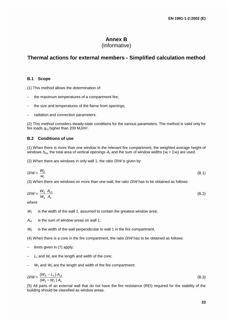
EN 1991-1-2:2002 (E)
33
Annex B(informative)
Thermal actions for external members - Simplified calculation method
B.1 Scope
(1) This method allows the determination of:
– the maximum temperatures of a compartment fire;
– the size and temperatures of the flame from openings;
– radiation and convection parameters.
(2) This method considers steady-state conditions for the various parameters. The method is valid only forfire loads qf,d higher than 200 MJ/m².
B.2 Conditions of use
(1) When there is more than one window in the relevant fire compartment, the weighted average height ofwindows heq, the total area of vertical openings Av and the sum of window widths (wt = Σwi) are used.
(2) When there are windows in only wall 1, the ratio D/W is given by:
D/W = t
2
wW
(B.1)
(3) When there are windows on more than one wall, the ratio D/W has to be obtained as follows:
D/W = v
1v
1
2
A
A
W
W(B.2)
where
W1 is the width of the wall 1, assumed to contain the greatest window area;
Av1 is the sum of window areas on wall 1;
W2 is the width of the wall perpendicular to wall 1 in the fire compartment.
(4) When there is a core in the fire compartment, the ratio D/W has to be obtained as follows:
– limits given in (7) apply;
– Lc and Wc are the length and width of the core;
– W1 and W2 are the length and width of the fire compartment:
D/W = vc1
1vc2
)(
)(
AWW
ALW
−−
(B.3)
(5) All parts of an external wall that do not have the fire resistance (REI) required for the stability of thebuilding should be classified as window areas.
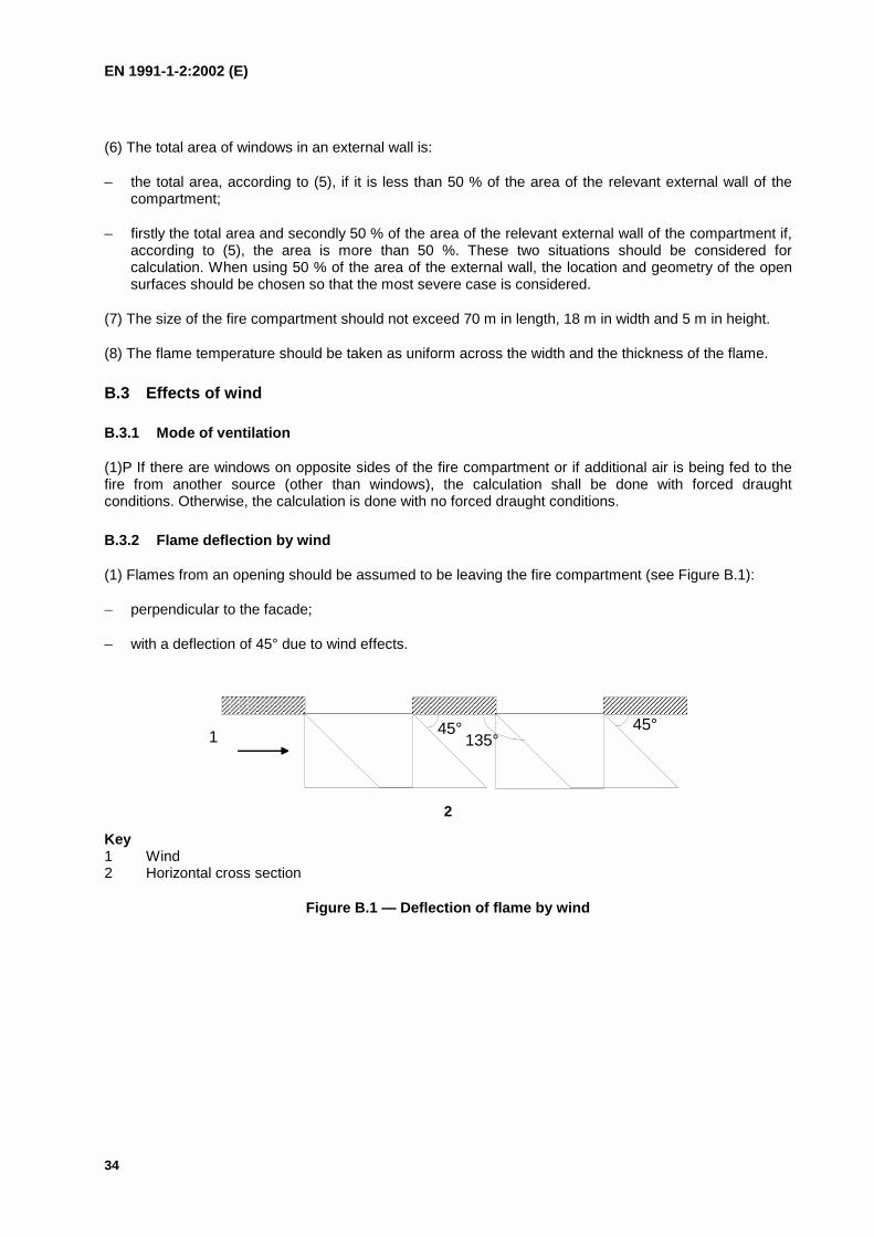
EN 1991-1-2:2002 (E)
34
(6) The total area of windows in an external wall is:
– the total area, according to (5), if it is less than 50 % of the area of the relevant external wall of thecompartment;
– firstly the total area and secondly 50 % of the area of the relevant external wall of the compartment if,according to (5), the area is more than 50 %. These two situations should be considered forcalculation. When using 50 % of the area of the external wall, the location and geometry of the opensurfaces should be chosen so that the most severe case is considered.
(7) The size of the fire compartment should not exceed 70 m in length, 18 m in width and 5 m in height.
(8) The flame temperature should be taken as uniform across the width and the thickness of the flame.
B.3 Effects of wind
B.3.1 Mode of ventilation
(1)P If there are windows on opposite sides of the fire compartment or if additional air is being fed to thefire from another source (other than windows), the calculation shall be done with forced draughtconditions. Otherwise, the calculation is done with no forced draught conditions.
B.3.2 Flame deflection by wind
(1) Flames from an opening should be assumed to be leaving the fire compartment (see Figure B.1):
– perpendicular to the facade;
– with a deflection of 45° due to wind effects.
1 45°135°
45°
2
Key1 Wind2 Horizontal cross section
Figure B.1 — Deflection of flame by wind
EN 1991-1-2:2002 (E)
35
B.4 Characteristics of fire and flames
B.4.1 No forced draught
(1) The rate of burning or the rate of heat release is given by:
−⋅=
−2/1
eqv
036,0
Fd,ff /)e1(15,3;/)(min
WD
hAqAQ Oτ [MW] (B.4)
(2) The temperature of the fire compartment is given by:
000286,02
11,0
f )e1()e1(0006 TOT O +−−= −−
(B.5)
(3) The flame height (see Figure B.2) is given by:
−
= 1
)(37,2;0max
3/2
2/1eqgv
eqLghA
QhL (B.6)
NOTE With ρg = 0,45 kg/m3 and g = 9,81 m/s2 , this equation may be simplified to:
eq
3/2
tL 9,1 h
wQ
L −
= (B.7)
wt
2 h / 3
Lh
L
L
eq
L
H
eq
1
2 h / 3eq
2 h / 3eq
2 h / 3eq
L L
heqL1
L H
horizontal cross section vertical cross section vertical cross section
⇒=3eq
L
hL
29eq
2eq2
H1
hhLL ≅+=
2eq
1
hL ≅
Lf = LL + L1 1
2eq
H2Lf 3
Lh
LLL +
−+=
heq<1,25wt wall above no wall above or heq>1,25wt
Figure B.2 — Flame dimensions, no through draught
EN 1991-1-2:2002 (E)
36
(4) The flame width is the window width (see Figure B.2).
(5) The flame depth is 2/3 of the window height: 2/3 heq (see Figure B.2).
(6) The horizontal projection of flames:
– in case of a wall existing above the window, is given by:
LH = heq/3 if heq ≤ 1,25 wt (B.8)
LH = 0,3 heq (heq / wt)0,54 if heq > 1,25 wt and distance to any other window > 4 wt (B.9)
LH = 0,454 heq (heq /2wt)0,54 in other cases (B.10)
– in case of a wall not existing above the window, is given by:
LH = 0,6 heq (LL/ heq)1/3 (B.11)
(7) The flame length along axis is given by:
when LL > 0
Lf = LL + heq /2 if wall exist above window or if heq ≤ 1,25 wt (B.12)
Lf = (LL 2 + (LH - heq /3 )2 )1/2 + heq /2 if no wall exist above window or if heq > 1,25 wt (B.13)
when LL = 0 , then Lf = 0
(8) The flame temperature at the window is given by:
Tw = 520 / ( 1 - 0,4725 (Lf ⋅ wt /Q)) + T0 [K] (B.14)
with Lf ⋅ wt /Q < 1
(9) The emissivity of flames at the window may be taken as ε f = 1,0
(10) The flame temperature along the axis is given by:
Tz = (Tw - T0) (1 - 0,4725 (Lx ⋅ wt / Q)) + T0 [K] (B.15)
with
Lx ⋅ wt /Q < 1
Lx is the axis length from the window to the point where the calculation is made
(11) The emissivity of flames may be taken as:
ε f = 1 - f3,0e d− (B.16)
where df is the flame thickness [m]
(12) The convective heat transfer coefficient is given by:
αc = 4,67 (1/deq)0,4 (Q/Av)
0,6 (B.17)
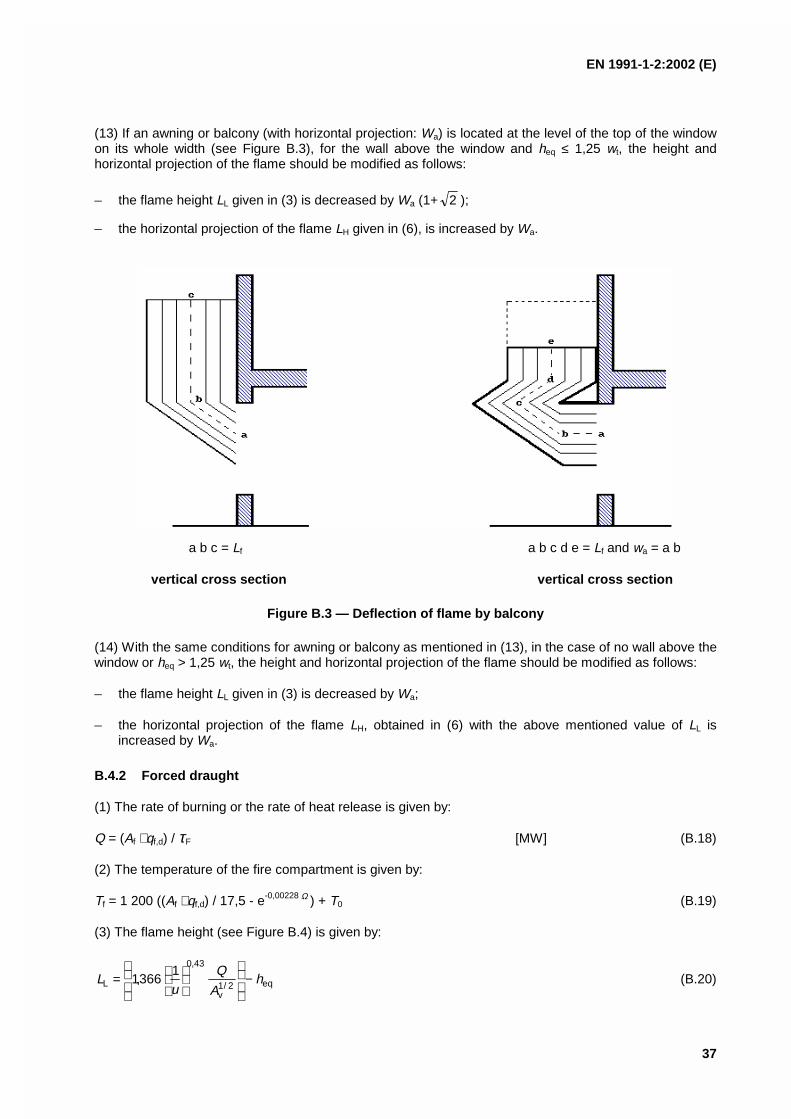
EN 1991-1-2:2002 (E)
37
(13) If an awning or balcony (with horizontal projection: Wa) is located at the level of the top of the windowon its whole width (see Figure B.3), for the wall above the window and heq ≤ 1,25 wt, the height andhorizontal projection of the flame should be modified as follows:
– the flame height LL given in (3) is decreased by Wa (1+ 2 );
– the horizontal projection of the flame LH given in (6), is increased by Wa.
a b c = Lf a b c d e = Lf and wa = a b
vertical cross section vertical cross section
Figure B.3 — Deflection of flame by balcony
(14) With the same conditions for awning or balcony as mentioned in (13), in the case of no wall above thewindow or heq > 1,25 wt, the height and horizontal projection of the flame should be modified as follows:
– the flame height LL given in (3) is decreased by Wa;
– the horizontal projection of the flame LH, obtained in (6) with the above mentioned value of LL isincreased by Wa.
B.4.2 Forced draught
(1) The rate of burning or the rate of heat release is given by:
Q = (Af ⋅ qf,d) / τF [MW] (B.18)
(2) The temperature of the fire compartment is given by:
Tf = 1 200 ((Af ⋅ qf,d) / 17,5 - e-0,00228 Ω ) + T0 (B.19)
(3) The flame height (see Figure B.4) is given by:
eq2/1v
43,0
L1
366,1 hA
Qu
L −
= (B.20)
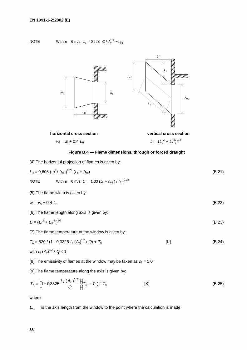
EN 1991-1-2:2002 (E)
38
NOTE With u = 6 m/s, eq2/1
vL /628,0 hAQL −≈
wtw
LH
f
L
L
L
h
f
eq
H
eq
h
L
horizontal cross section vertical cross section
wf = wt + 0,4 LH Lf = (LL2 + LH
2) 1/2
Figure B.4 — Flame dimensions, through or forced draught
(4) The horizontal projection of flames is given by:
LH = 0,605 ( u2 / heq )0,22 (LL + heq) (B.21)
NOTE With u = 6 m/s, LH = 1,33 (LL + heq ) / heq 0,22
(5) The flame width is given by:
wf = wt + 0,4 LH (B.22)
(6) The flame length along axis is given by:
Lf = (LL2 + LH
2 )1/2 (B.23)
(7) The flame temperature at the window is given by:
Tw = 520 / (1 - 0,3325 Lf (Av)1/2 / Q) + T0 [K] (B.24)
with Lf (Av)1/2 / Q < 1
(8) The emissivity of flames at the window may be taken as ε f = 1,0
(9) The flame temperature along the axis is given by:
00w
2/1vx
z )()(
3325,01 TTTQ
ALT +−
−= [K] (B.25)
where
Lx is the axis length from the window to the point where the calculation is made
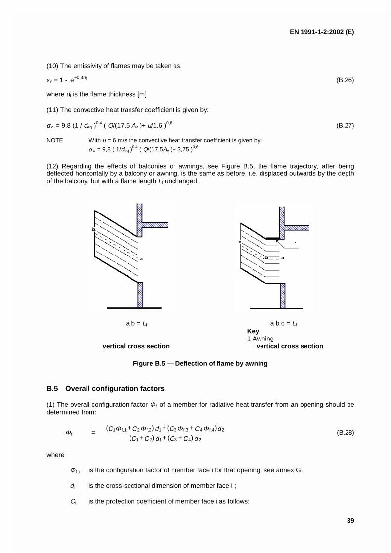
EN 1991-1-2:2002 (E)
39
(10) The emissivity of flames may be taken as:
ε f = 1 - f3,0e d− (B.26)
where df is the flame thickness [m]
(11) The convective heat transfer coefficient is given by:
αc = 9,8 (1 / deq )0,4 ( Q/(17,5 Av )+ u/1,6 )0,6 (B.27)
NOTE With u = 6 m/s the convective heat transfer coefficient is given by:
α c = 9,8 ( 1/deq )0,4 ( Q/(17,5Av )+ 3,75 )0,6
(12) Regarding the effects of balconies or awnings, see Figure B.5, the flame trajectory, after beingdeflected horizontally by a balcony or awning, is the same as before, i.e. displaced outwards by the depthof the balcony, but with a flame length Lf unchanged.
a b = Lf a b c = Lf
Key1 Awning
vertical cross section vertical cross section
Figure B.5 — Deflection of flame by awning
B.5 Overall configuration factors
(1) The overall configuration factor Φ f of a member for radiative heat transfer from an opening should bedetermined from:
Φ f =dCCdCC
dCCdCC
243121
2f,44f,331f,22f,11
) + ( + ) + (
) + ( + ) + ((B.28)
where
Φ f ,i is the configuration factor of member face i for that opening, see annex G;
di is the cross-sectional dimension of member face i ;
Ci is the protection coefficient of member face i as follows:

EN 1991-1-2:2002 (E)
40
- for a protected face: Ci = 0
- for an unprotected face: Ci = 1
(2) The configuration factor Φ f ,i for a member face from which the opening is not visible should be takenas zero.
(3) The overall configuration factor Φz of a member for radiative heat transfer from a flame should bedetermined from:
Φz =dCCdCC
dCCdCC
243121
2z,44z,331z,22z,11
) + ( + ) + (
) + ( + ) + ((B.29)
where
Φz,i is the configuration factor of member face i for that flame, see annex G.
(4) The configuration factors Φz,i of individual member faces for radiative heat transfer from flames may bebased on equivalent rectangular flame dimensions. The dimensions and locations of equivalent rectanglesrepresenting the front and sides of a flame for this purpose should be determined as given in annex G.For all other purposes, the flame dimensions given in B.4 of this annex should be used.
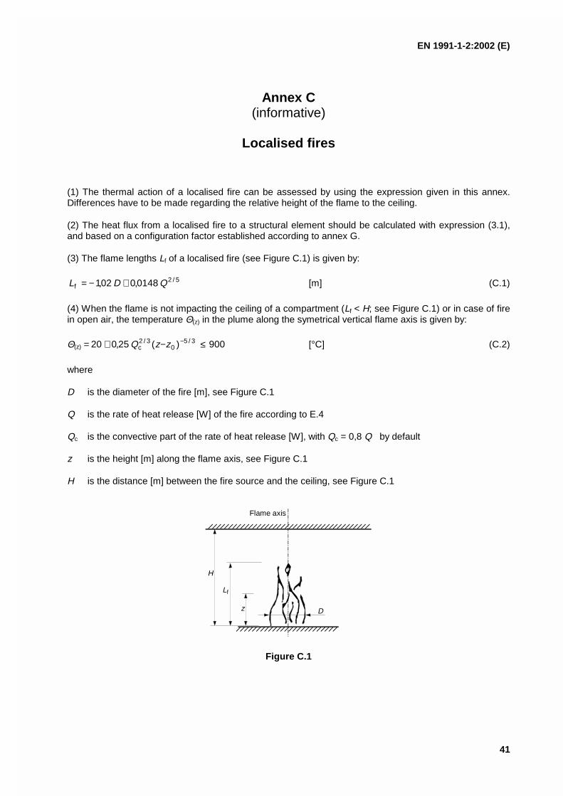
EN 1991-1-2:2002 (E)
41
Annex C(informative)
Localised fires
(1) The thermal action of a localised fire can be assessed by using the expression given in this annex.Differences have to be made regarding the relative height of the flame to the ceiling.
(2) The heat flux from a localised fire to a structural element should be calculated with expression (3.1),and based on a configuration factor established according to annex G.
(3) The flame lengths Lf of a localised fire (see Figure C.1) is given by:
5/2f 0148,002,1 QDL +−= [m] (C.1)
(4) When the flame is not impacting the ceiling of a compartment (Lf < H; see Figure C.1) or in case of firein open air, the temperature Θ(z) in the plume along the symetrical vertical flame axis is given by:
Θ(z) 900)(25,020 3/50
3/2c ≤−+= −zzQ [°C] (C.2)
where
D is the diameter of the fire [m], see Figure C.1
Q is the rate of heat release [W] of the fire according to E.4
Qc is the convective part of the rate of heat release [W], with Qc = 0,8 Q by default
z is the height [m] along the flame axis, see Figure C.1
H is the distance [m] between the fire source and the ceiling, see Figure C.1
Flame axis
L
z D
f
H
Figure C.1
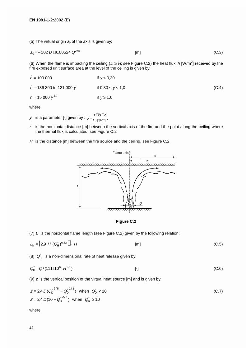
EN 1991-1-2:2002 (E)
42
(5) The virtual origin z0 of the axis is given by:
5/20 00524,002,1 QDz +−= [m] (C.3)
(6) When the flame is impacting the ceiling (Lf ≥ H; see Figure C.2) the heat flux h [W/m2] received by thefire exposed unit surface area at the level of the ceiling is given by:
h = 100 000 if y ≤ 0,30
h = 136 300 to 121 000 y if 0,30 < y < 1,0 (C.4)
h = 15 000 y-3,7 if y ≥ 1,0
where
y is a parameter [-] given by : '
'
h zHLzHr
y++
++=
r is the horizontal distance [m] between the vertical axis of the fire and the point along the ceiling wherethe thermal flux is calculated, see Figure C.2
H is the distance [m] between the fire source and the ceiling, see Figure C.2
Flame axis
Lh
r
H
D
Figure C.2
(7) Lh is the horizontal flame length (see Figure C.2) given by the following relation:
( ) HQHL −= 33,0*Hh )(9,2 [m] (C.5)
(8) *HQ is a non-dimensional rate of heat release given by:
)1011,1(/ 5,26*
H HQQ ⋅⋅= [-] (C.6) (9) z' is the vertical position of the virtual heat source [m] and is given by:
0,1when)(4,2' *D
3/2*D
5/2*D <−= QQQDz (C.7)
0,1when)0,1(4,2' *D
5/2*D ≥−= QQDz
where
EN 1991-1-2:2002 (E)
43
)1011,1(/ 5,26*D DQQ ⋅⋅= [-] (C.8)
(10) The net heat flux h net received by the fire exposed unit surface area at the level of the ceiling, is givenby : h net = h - αc ⋅ (Θm - 20) - Φ ⋅ εm ⋅ ε f ⋅ σ ⋅ [ (Θm + 273)4 - (293)4 ] (C.9) where the various coefficients depend on expressions (3.2), (3.3) and (C.4).
(11) The rules given in (3) to (10) inclusive are valid if the following conditions are met:
− the diameter of the fire is limited by D ≤ 10 m;
− the rate of heat release of the fire is limited by Q ≤ 50 MW.
(12) In case of several separate localised fires, expression (C.4) may be used in order to get the differentindividual heat fluxes h 1, h 2 . . . received by the fire exposed unit surface area at the level of the ceiling.The total heat flux may be taken as: h tot = h 1 + h 2...≤ 100 000 [W/m²] (C.10)
EN 1991-1-2:2002 (E)
44
Annex D(informative)
Advanced fire models
D.1 One-zone models
(1) A one-zone model should apply for post-flashover conditions. Homogeneous temperature, density,internal energy and pressure of the gas are assumed in the compartment.
(2) The temperature should be calculated considering:
– the resolution of mass conservation and energy conservation equations;
– the exchange of mass between the internal gas, the external gas (through openings) and the fire(pyrolysis rate);
– the exchange of energy between the fire, internal gas, walls and openings.
(3) The ideal gas law considered is:
Pint = ρg R Tg [N/m²] (D.1)
(4) The mass balance of the compartment gases is written as
fioutindd
mmmtm
+−= [kg/s] (D.2)
where
dtdm
is the rate of change of gas mass in the fire compartment
outm is the rate of gas mass going out through the openings
inm is the rate of gas mass coming in through the openings
fim is the rate of pyrolysis products generated
(5) The rate of change of gas mass and the rate of pyrolysis may be neglected. Thus
outin mm = (D.3)
These mass flows may be calculated based on static pressure due to density differences between air atambient and high temperatures, respectively.
(6) The energy balance of the gases in the fire compartment may be taken as:
radwallinoutg
dt
dQQQQQ
E−−+−= [W] (D.4)
where
EN 1991-1-2:2002 (E)
45
Eg is the internal energy of gas [J]
Q is the rate of heat release of the fire [W]
outQ = fout Tcm
inQ = ambin Tcm
wallQ = (At - Ah,v) h net , is the loss of energy to the enclosure surfaces
radQ = 4fv,h TA , is the loss of energy by radiation through the openings
with:
c is the specific heat [J/kgK]
h net is given by expression (3.1)
m is the gas mass rate [kg/s]
T is the temperature [K]
D.2 Two-zone models
(1) A two-zone model is based on the assumption of accumulation of combustion products in a layerbeneath the ceiling, with a horizontal interface. Different zones are defined: the upper layer, the lowerlayer, the fire and its plume, the external gas and walls.
(2) In the upper layer, uniform characteristics of the gas may be assumed.
(3) The exchanges of mass, energy and chemical substance may be calculated between these differentzones.
(4) In a given fire compartment with a uniformly distributed fire load, a two-zone fire model may developinto a one-zone fire in one of the following situations:
– if the gas temperature of the upper layer gets higher than 500 °C,
– if the upper layer is growing so to cover 80% of the compartment height.
D.3 Computational fluid dynamic models
(1) A computational fluid dynamic model may be used to solve numerically the partial differential equationsgiving, in all points of the compartment, the thermo-dynamic and aero-dynamic variables.
NOTE Computational fluid dynamic models, or CFD, analyse systems involving fluid flow, heat transfer andassociated phenomena by solving the fundamental equations of the fluid flow. These equations represent themathematical statements of the conservation laws of physics:
– the mass of a fluid is conserved;
– the rate of change of momentum equals the sum of the forces on a fluid particle (Newton’s second law);
– the rate of change of energy is equal to the sum of the rate of heat increase and the rate of work done ona fluid particle (first law of thermodynamics).
EN 1991-1-2:2002 (E)
46
Annex E(informative)
Fire load densities
E.1 General
(1) The fire load density used in calculations should be a design value, either based on measurements orin special cases based on fire resistance requirements given in national regulations.
(2) The design value may be determined:
– from a national fire load classification of occupancies; and/or
– specific for an individual project by performing a fire load survey.
(3) The design value of the fire load qf,d is defined as:
qf,d = qf,k ⋅ m ⋅ δq 1 ⋅ δq 2 ⋅ δn [MJ/m²] (E.1)
where
m is the combustion factor (see E.3)
δq 1 is a factor taking into account the fire activation risk due to the size of thecompartment (see Table E.1)
δq 2 is a factor taking into account the fire activation risk due to the type ofoccupancy (see Table E.1)
∏=
=10
1inin δδ
is a factor taking into account the different active fire fighting measures i(sprinkler, detection, automatic alarm transmission, firemen …). These activemeasures are generally imposed for life safety reason (see Table E.2 andclauses (4) and (5)).
qf,k is the characteristic fire load density per unit floor area [MJ/m²](see f.i. Table E.4)
Table E.1 — Factors δδq 1 , δδq 2
1,90
2,00
2,13
Compartmentfloor area A [m²]f
1,50
1,1025
250
2 500
5 000
10 000
Danger ofFire Activation
δδ q1
0,78
1,00
1,22
1,44
1,66
Examplesof
Occupancies
artgallery, museum,swimming pool
offices,residence, hotel,paper industry
manufactory for machinery& engines
chemical laboratory,painting workshop
manufactory of fireworksor paints
Danger ofFire Activation
δδ q2
EN 1991-1-2:2002 (E)
47
Table E.2 — Factors δδn i
AutomaticWater
ExtinguishingSystem
IndependentWater
Supplies
Automatic fireDetection& Alarm
byHeat
bySmoke
AutomaticAlarm
Transmissionto
Fire Brigade
Function of Active Fire Fighting Measuresδ ni
0 1 2
Automatic Fire Suppression Automatic Fire Detection
δ n1 δn2 δ n3 δn4 δn5
0,61 0,87 or 0,73 0,871,0 0,87 0,7
WorkFire
Brigade
Off SiteFire
Brigade
SafeAccessRoutes
FireFightingDevices
SmokeExhaustSystem
δn10
Manual Fire Suppression
δ n6 δn7 δn8 δn9
0,61 or 0,78 0,9 or 1or 1,5 1,0 or 1,5 1,0 or 1,5
(4) For the normal fire fighting measures, which should almost always be present, such as the safeaccess routes, fire fighting devices, and smoke exhaust systems in staircases, the δn i values of Table E.2should be taken as 1,0. However, if these fire fighting measures have not been foreseen, thecorresponding δn i value should be taken as 1,5.
(5) If staircases are put under overpressure in case of fire alarm, the factor δn8 of Table E.2 may be takenas 0,9.
(6) The preceding approach is based on the assumption that the requirements in the relevant EuropeanStandards on sprinklers, detection, alarm, smoke exhaust systems are met, see also 1.3. However localcircumstances may influence the numbers given in Table E.2. Reference is made to the BackgroundDocument CEN/TC250/SC1/N300A.
E.2 Determination of fire load densities
E.2.1 General
(1) The fire load should consist of all combustible building contents and the relevant combustible parts ofthe construction, including linings and finishings. Combustible parts of the combustion which do not charduring the fire need not to be taken into account.
(2) The following clauses apply for the determination of fire load densities:
– from a fire load classification of occupancies (see E.2.5); and/or
– specific for an individual project (see E.2.6).
(3) Where fire load densities are determined from a fire load classification of occupancies, fire loads aredistinguished as:
– fire loads from the occupancy, given by the classification;
– fire loads from the building (construction elements, linings and finishings) which are generally notincluded in the classification and are then determined according to the following clauses, as relevant.
E.2.2 Definitions
(1) The characteristic fire load is defined as:
Qfi,k = Σ Mk,i ⋅ Hui ⋅ Ψi = Σ Qfi,k,i [MJ] (E.2)
where
EN 1991-1-2:2002 (E)
48
Mk,i is the amount of combustible material [kg], according to (3) and (4)
Hui is the net calorific value [MJ/kg], see (E.2.4)
[Ψi] is the optional factor for assessing protected fire loads, see (E.2.3)
(2) The characteristic fire load density qf,k per unit area is defined as:
qf,k = Qfi,k /A [MJ/m2] (E.3)
where
A is the floor area (Af) of the fire compartment or reference space, or inner surface area (At) of the firecompartment, giving qf,k or qt,k
(3) Permanent fire loads, which are not expected to vary during the service life of a structure, should beintroduced by their expected values resulting from the survey.
(4) Variable fire loads, which may vary during the service life of a structure, should be represented byvalues, which are expected not to be exceeded during 80 % of time.
E.2.3 Protected fire loads
(1) Fire loads in containments which are designed to survive fire exposure need not be considered.
(2) Fire loads in non-combustible containments with no specific fire design, but which remain intact duringfire exposure, may be considered as follows:
The largest fire load, but at least 10 % of the protected fire loads, is associated with Ψi = 1,0.
If this fire load plus the unprotected fire loads are not sufficient to heat the remaining protected fire loadsbeyond ignition temperature, then the remaining protected fire loads may be associated with Ψi = 0,0.
Otherwise, Ψi values need to be assessed individually.
E.2.4 Net calorific values
(1) Net calorific values should be determined according to EN ISO 1716:2002.
(2) The moisture content of materials may be taken into account as follows:
Hu = Hu0 (1 - 0,01 u) - 0,025 u [MJ/kg] (E.4)
where
u is the moisture content expressed as percentage of dry weight
Hu0 is the net calorific value of dry materials
(3) Net calorific values of some solids, liquids and gases are given in Table E.3.

EN 1991-1-2:2002 (E)
49
Table E.3 — Net calorific values Hu [MJ/kg] of combustible materials for calculation of fire loads
SolidsWood 17,5Other cellulosic materials
• Clothes• Cork• Cotton• Paper, cardboard• Silk• Straw• Wool
20
Carbon• Anthracit• Charcoal• Coal
30
ChemicalsParaffin series
• Methane• Ethane• Propane• Butane
50
Olefin series• Ethylene• Propylen• Butene
45
Aromatic series• Benzene• Toluene
40
Alcohols• Methanol• Ethanol• Ethyl alcohol
30
Fuels• Gasoline, petroleum• Diesel
45
Pure hydrocarbons plastics• Polyethylene• Polystyrene• Polypropylene
40
Other productsABS (plastic) 35
Polyester (plastic) 30
Polyisocyanerat and polyurethane (plastics) 25
Polyvinylchloride, PVC (plastic) 20
Bitumen, asphalt 40
Leather 20
Linoleum 20
Rubber tyre 30
NOTE The values given in this table are not applicable for calculatingenergy content of fuels.
EN 1991-1-2:2002 (E)
50
E.2.5 Fire load classification of occupancies
(1) The fire load densities should be classified according to occupancy, be related to the floor area, and beused as characteristic fire load densities qf,k [MJ/m²], as given in Table E.4.
Table E.4 — Fire load densities qf,k [MJ/m²] for different occupancies
Occupancy Average 80% Fractile
Dwelling 780 948
Hospital (room) 230 280
Hotel (room) 310 377
Library 1 500 1 824
Office 420 511
Classroom of a school 285 347
Shopping centre 600 730
Theatre (cinema) 300 365
Transport (public space) 100 122
NOTE Gumbel distribution is assumed for the 80 % fractile.
(2) The values of the fire load density qf,k given in Table E.4 are valid in case of a factor δq 2 equal to 1,0(see Table E.1).
(3) The fire loads in Table E.4 are valid for ordinary compartments in connection with the here givenoccupancies. Special rooms are considered according to E.2.2.
(4) Fire loads from the building (construction elements, linings and finishings) should be determinedaccording to E.2.2. These should be added to the fire load densities of (1) if relevant.
E.2.6 Individual assessment of fire load densities
(1) In the absence of occupancy classes, fire load densities may be specifically determined for anindividual project by performing a survey of fire loads from the occupancy.
(2) The fire loads and their local arrangement should be estimated considering the intended use,furnishing and installations, variations with time, unfavourable trends and possible modifications ofoccupancy.
(3) Where available, a survey should be performed in a comparable existing project, such that onlypossible differences between the intended and existing project need to be specified by the client.
E.3 Combustion behaviour
(1) The combustion behaviour should be considered in function of the occupancy and of the type of fireload.
(2) For mainly cellulosic materials, the combustion factor may be assumed as m = 0,8.
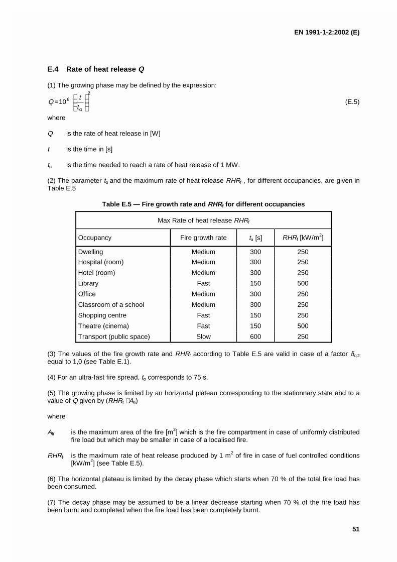
EN 1991-1-2:2002 (E)
51
E.4 Rate of heat release Q
(1) The growing phase may be defined by the expression:2
610
=
αtt
Q (E.5)
where
Q is the rate of heat release in [W]
t is the time in [s]
tα is the time needed to reach a rate of heat release of 1 MW.
(2) The parameter tα and the maximum rate of heat release RHRf , for different occupancies, are given inTable E.5
Table E.5 — Fire growth rate and RHRf for different occupancies
Max Rate of heat release RHRf
Occupancy Fire growth rate tα [s] RHRf [kW/m2]
Dwelling Medium 300 250
Hospital (room) Medium 300 250
Hotel (room) Medium 300 250
Library Fast 150 500
Office Medium 300 250
Classroom of a school Medium 300 250
Shopping centre Fast 150 250
Theatre (cinema) Fast 150 500
Transport (public space) Slow 600 250
(3) The values of the fire growth rate and RHRf according to Table E.5 are valid in case of a factor δq 2
equal to 1,0 (see Table E.1).
(4) For an ultra-fast fire spread, tα corresponds to 75 s.
(5) The growing phase is limited by an horizontal plateau corresponding to the stationnary state and to avalue of Q given by (RHRf ⋅ Afi)
where
Afi is the maximum area of the fire [m2] which is the fire compartment in case of uniformly distributedfire load but which may be smaller in case of a localised fire.
RHRf is the maximum rate of heat release produced by 1 m2 of fire in case of fuel controlled conditions[kW/m2] (see Table E.5).
(6) The horizontal plateau is limited by the decay phase which starts when 70 % of the total fire load hasbeen consumed.
(7) The decay phase may be assumed to be a linear decrease starting when 70 % of the fire load hasbeen burnt and completed when the fire load has been completely burnt.
EN 1991-1-2:2002 (E)
52
(8) If the fire is ventilation controlled, this plateau level has to be reduced following the available oxygencontent, either automatically in case of the use of a computer program based on one zone model or by thesimplified expression:
eqvumax 10,0 hAHmQ ⋅⋅⋅⋅= [MW] (E.6)
where
Av is the opening area [m2]
heq is the mean height of the openings [m]
Hu is the net calorific value of wood with Hu = 17,5 MJ/kg
m is the combustion factor with m = 0,8
(9) When the maximum level of the rate of heat release is reduced in case of ventilation controlledcondition, the curve of the rate of heat release has to be extended to correspond to the available energygiven by the fire load. If the curve is not extended, it is then assumed that there is external burning, whichinduces a lower gas temperature in the compartment.
EN 1991-1-2:2002 (E)
53
Annex F(informative)
Equivalent time of fire exposure
(1) The following approach may be used where the design of members is based on tabulated data orother simplified rules, related to the standard fire exposure.
NOTE The method given in this annex is material dependent. It is not applicable to composite steel and concreteor timber constructions.
(2) If fire load densities are specified without specific consideration of the combustion behaviour (seeannex E), then this approach should be limited to fire compartments with mainly cellulosic type fire loads.
(3) The equivalent time of standard fire exposure is defined by:
te,d = (qf,d ⋅ kb ⋅ wf ) kc or
te,d = (qt,d ⋅ kb ⋅ wt ) kc [min] (F.1)
where
qf,d is the design fire load density according to annex E, whereby qt,d = qf,d ⋅ Af / At
kb is the conversion factor according to (4)
wf is the ventilation factor according to (5), whereby wt = wf ⋅ At / Af
kc is the correction factor function of the material composing structural cross-sections and defined inTable F.1.
Table F.1 — Correction factor kc in order to cover various materials.(O is the opening factor defined in annex A)
Cross-section material Correction factor kc
Reinforced concrete 1,0
Protected steel 1,0
Not protected steel 13,7 ⋅ O
(4) Where no detailed assessment of the thermal properties of the enclosure is made, the conversionfactor kb may be taken as:
kb = 0,07 [min ⋅ m2/MJ] when qd is given in [MJ/m2] (F.2)
otherwise kb may be related to the thermal property b = )( of the enclosure according to Table F.2.
For determining b for multiple layers of material or different materials in walls, floor, ceiling, see annex A(5) and (6).
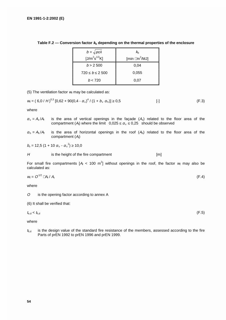
EN 1991-1-2:2002 (E)
54
Table F.2 — Conversion factor kb depending on the thermal properties of the enclosure
b = kb
[J/m2s1/2K] [min ⋅ m2/MJ]
b > 2 500 0,04
720 ≤ b ≤ 2 500 0,055
b < 720 0,07
(5) The ventilation factor wf may be calculated as:
wf = ( 6,0 / H )0,3 [0,62 + 90(0,4 - αv)4 / (1 + bv αh)] ≥ 0,5 [-] (F.3)
where
αv = Av /Af is the area of vertical openings in the façade (Av) related to the floor area of thecompartment (Af) where the limit 0,025 ≤ αv ≤ 0,25 should be observed
αh = Ah /Af is the area of horizontal openings in the roof (Ah) related to the floor area of thecompartment (Af)
bv = 12,5 (1 + 10 αv - αv2) ≥ 10,0
H is the height of the fire compartment [m]
For small fire compartments [Af < 100 m2] without openings in the roof, the factor wf may also becalculated as:
wf = O-1/2 ⋅ Af / At (F.4)
where
O is the opening factor according to annex A
(6) It shall be verified that:
te,d < tfi,d (F.5)
where
tfi,d is the design value of the standard fire resistance of the members, assessed according to the fireParts of prEN 1992 to prEN 1996 and prEN 1999.
EN 1991-1-2:2002 (E)
55
Annex G(informative)
Configuration factor
G.1 General
(1) The configuration factor Φ is defined in 1.5.4.1, which in a mathematical form is given by:
2221
212d1d dA
S
coscosdF
−− =
(G.1)
The configuration factor measures the fraction of the total radiative heat leaving a given radiating surfacethat arrives at a given receiving surface. Its value depends on the size of the radiating surface, on thedistance from the radiating surface to the receiving surface and on their relative orientation (seeFigure G.1).
dA1
θ1
dA1
θ2
dA2
S1-2
Figure G.1 — Radiative heat transfer between two infinitesimal surface areas
(2) In cases where the radiator has uniform temperature and emissivity, the definition can be simplified to :“the solid angle within which the radiating environment can be seen from a particular infinitesimal surfacearea, divided by 2π.”
(3) The radiative heat transfer to an infinitesimal area of a convex member surface is determined by theposition and the size of the fire only (position effect).
(4) The radiative heat transfer to an infinitesimal area of a concave member surface is determined by theposition and the size of the fire (position effect) as well as by the radiation from other parts of the member(shadow effects).
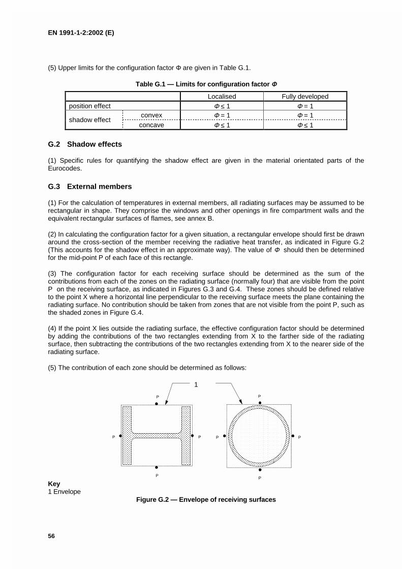
EN 1991-1-2:2002 (E)
56
(5) Upper limits for the configuration factor Φ are given in Table G.1.
Table G.1 — Limits for configuration factor ΦΦ
Localised Fully developedposition effect Φ ≤ 1 Φ = 1
convex Φ = 1 Φ = 1shadow effect
concave Φ ≤ 1 Φ ≤ 1
G.2 Shadow effects
(1) Specific rules for quantifying the shadow effect are given in the material orientated parts of theEurocodes.
G.3 External members
(1) For the calculation of temperatures in external members, all radiating surfaces may be assumed to berectangular in shape. They comprise the windows and other openings in fire compartment walls and theequivalent rectangular surfaces of flames, see annex B.
(2) In calculating the configuration factor for a given situation, a rectangular envelope should first be drawnaround the cross-section of the member receiving the radiative heat transfer, as indicated in Figure G.2(This accounts for the shadow effect in an approximate way). The value of Φ should then be determinedfor the mid-point P of each face of this rectangle.
(3) The configuration factor for each receiving surface should be determined as the sum of thecontributions from each of the zones on the radiating surface (normally four) that are visible from the pointP on the receiving surface, as indicated in Figures G.3 and G.4. These zones should be defined relativeto the point X where a horizontal line perpendicular to the receiving surface meets the plane containing theradiating surface. No contribution should be taken from zones that are not visible from the point P, such asthe shaded zones in Figure G.4.
(4) If the point X lies outside the radiating surface, the effective configuration factor should be determinedby adding the contributions of the two rectangles extending from X to the farther side of the radiatingsurface, then subtracting the contributions of the two rectangles extending from X to the nearer side of theradiating surface.
(5) The contribution of each zone should be determined as follows:
P
P
P
P
P
P
P
P
1
Key1 Envelope
Figure G.2 — Envelope of receiving surfaces
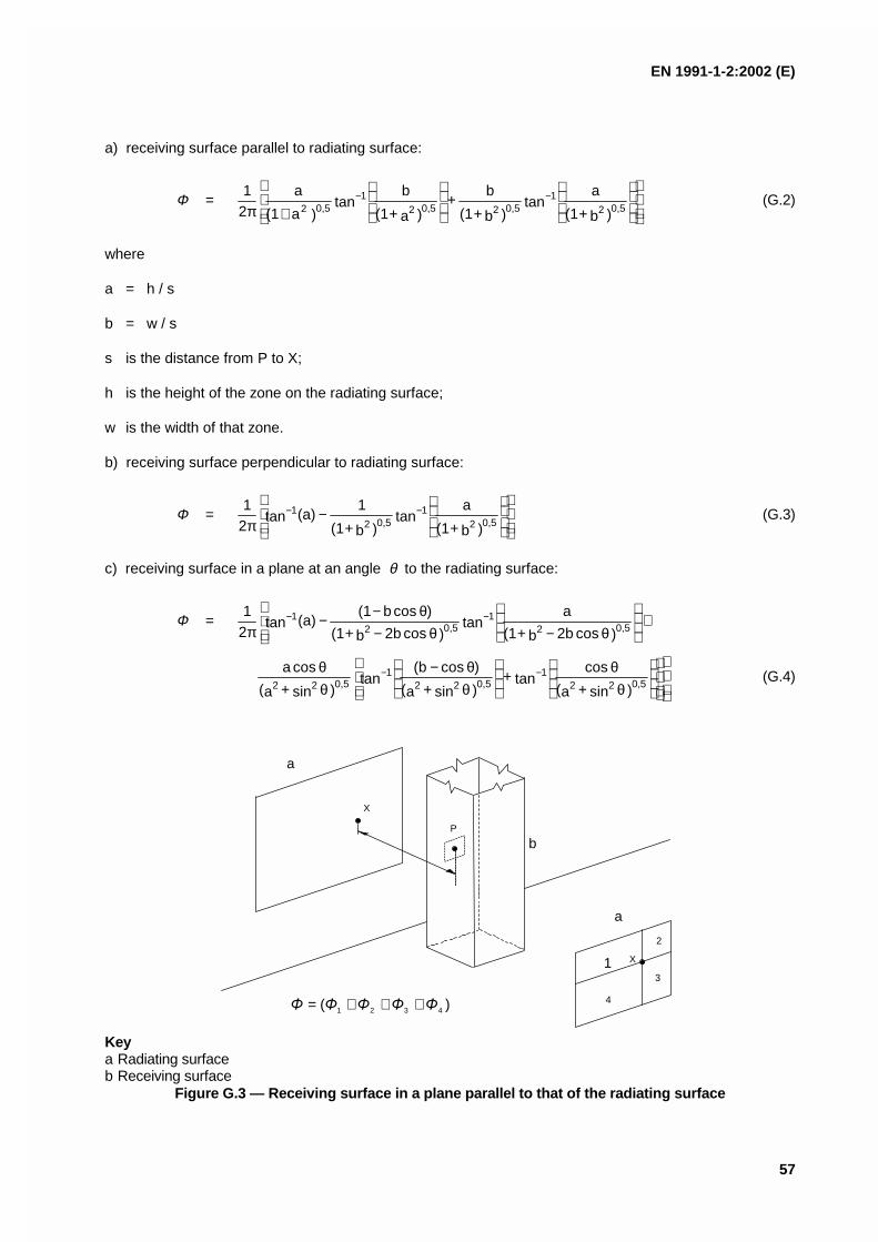
EN 1991-1-2:2002 (E)
57
a) receiving surface parallel to radiating surface:
Φ =
+π−−
)b + (1
atan
)b + (1
b +
)a + (1
btan
)a (1
a21
0,521
0,520,521
0,52(G.2)
where
a = h / s
b = w / s
s is the distance from P to X;
h is the height of the zone on the radiating surface;
w is the width of that zone.
b) receiving surface perpendicular to radiating surface:
Φ =
−
π−−
)b + (1
atan
)b + (1
1 (a)tan
21
0,521
0,521 (G.3)
c) receiving surface in a plane at an angle θ to the radiating surface:
Φ =
+
θ−θ−θ−−
π−−
)cos2b b + (1
atan
)cos2b b + (1
)cosb (1 (a)tan
21
0,521
0,521
θθ
θθ−
θθ −−
)sin + a(
costan +
)sin + a(
)cos (btan
)sin + a(
cosa
0,5221
0,5221
0,522(G.4)
X
P
X1
4
a
a
b
2
3
Keya Radiating surfaceb Receiving surface
Figure G.3 — Receiving surface in a plane parallel to that of the radiating surface
)( 4321 +++=
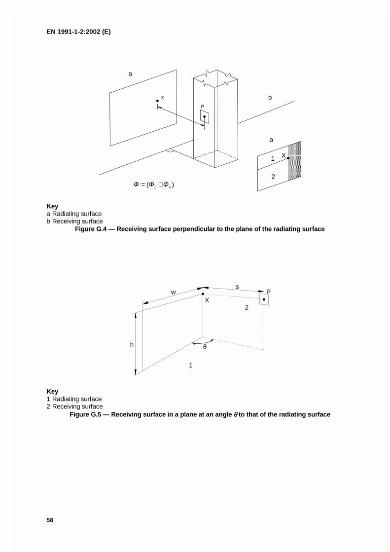
EN 1991-1-2:2002 (E)
58
X
P
X1
2
a
a
b
Keya Radiating surfaceb Receiving surface
Figure G.4 — Receiving surface perpendicular to the plane of the radiating surface
X
h
ws
θ
P
1
2
Key1 Radiating surface2 Receiving surface
Figure G.5 — Receiving surface in a plane at an angle θθ to that of the radiating surface
)( 21 +=

EN 1991-1-2:2002 (E)
59
Bibliography
EN ISO 1716:2002, Reaction to fire tests for building products - Determination of the heat of combustion(ISO 1716:2002).
EN 1363-2, Fire resistance tests - Part 2: Alternative and additional procedures.

EUROPEAN STANDARD
NORME EUROPÉENNE
EUROPÄISCHE NORM
EN 1991-1-3
July 2003
ICS 91.010.30 Supersedes ENV 1991-2-3:1995
English version
Eurocode 1 - Actions on structures - Part 1-3: General actions -Snow loads
Eurocode 1 - Actions sur les structures - Partie 1-3: Actionsgénérales - Charges de neige
Eurocode 1 - Einwirkungen auf Tragwerke - Teil 1-3:Allgemeine Einwirkungen-Schneelasten
This European Standard was approved by CEN on 9 October 2002.
CEN members are bound to comply with the CEN/CENELEC Internal Regulations which stipulate the conditions for giving this EuropeanStandard the status of a national standard without any alteration. Up-to-date lists and bibliographical references concerning such nationalstandards may be obtained on application to the Management Centre or to any CEN member.
This European Standard exists in three official versions (English, French, German). A version in any other language made by translationunder the responsibility of a CEN member into its own language and notified to the Management Centre has the same status as the officialversions.
CEN members are the national standards bodies of Austria, Belgium, Czech Republic, Denmark, Finland, France, Germany, Greece,Hungary, Iceland, Ireland, Italy, Luxembourg, Malta, Netherlands, Norway, Portugal, Slovakia, Spain, Sweden, Switzerland and UnitedKingdom.
EUROPEAN COMMITTEE FOR STANDARDIZATIONC OM ITÉ EUR OP ÉEN DE NOR M ALIS AT IONEUROPÄISCHES KOMITEE FÜR NORMUNG
Management Centre: rue de Stassart, 36 B-1050 Brussels
© 2003 CEN All rights of exploitation in any form and by any means reservedworldwide for CEN national Members.
Ref. No. EN 1991-1-3:2003 E
EN 1991-1-3:2003 (E)
2
CONTENTS Page
Foreword 4
1. Section 1 General 8
1.1. Scope 8
1.2. Normative references 9
1.3. Assumptions 9
1.4. Distinction between Principles and Application Rules 9
1.5. Design assisted by testing 9
1.6. Terms and Definitions 10
1.7. Symbols 11
2. Section 2 Classification of actions 13
3. Section 3 Design situations 14
3.1. General 14
3.2. Normal conditions 14
3.3. Exceptional conditions 14
4. Section 4 Snow load on the ground 16
4.1. Characteristic values 16
4.2. Other representative values 16
4.3. Treatment of exceptional snow loads on the ground 17
5. Section 5 Snow load on roofs 17
5.1. Nature of the load 17
5.2. Load arrangements 18
5.3. Roof shape coefficients 205.3.1. General 205.3.2. Monopitch roofs 215.3.3. Pitched roofs 225.3.4. Multi-span roofs 235.3.5. Cylindrical roofs 245.3.6. Roof abutting and close to taller construction works25
6. Section 6 Local effects 28
6.1. General 28
6.2. Drifting at projections and obstructions 28
6.3. Snow overhanging the edge of a roof 29
6.4. Snow loads on snowguards and other obstacles 30
EN 1991-1-3:2003 (E)
3
ANNEX A 31
Design situations and load arrangements to be used for differentlocations 31
ANNEX B 33
Snow load shape coefficients for exceptional snow drifts 33
ANNEX C 38
European Ground Snow Load Maps 38
ANNEX D 53
Adjustment of the ground snow load according to return period 53
ANNEX E 55
Bulk weight density of snow 55
Bibliography 56

EN 1991-1-3:2003 (E)
4
Foreword
This document (EN 1991-1-3:2003) has been prepared by TechnicalCommittee CEN/TC250 “Structural Eurocodes”, the Secretariat of which is heldby BSI.
This European Standard shall be given the status of a National Standard,either by publication of an identical text or by endorsement, at the latest byJanuary 2004, and conflicting National Standards shall will be withdrawn atlatest by January 2004.
This document supersedes ENV 1991-2-3:1995.
CEN/TC250 is responsible for all Structural Eurocodes.
Annexes A and B are normative. Annexes C, D and E are informative.
According to the CEN-CENELEC Internal Regulations, the National StandardOrganisations of the following countries are bound to implement this EuropeanStandard: Austria, Belgium, Czech Republic, Denmark, Finland, France,Germany, Greece, Hungary, Iceland, Ireland, Italy, Luxembourg, Malta,Netherlands, Norway, Portugal, Slovakia, Spain, Sweden, Switzerland and theUnited Kingdom.
Background of the Eurocode programme
In 1975, the Commission of the European Community decided on an actionprogramme in the field of construction, based on article 95 of the Treaty. Theobjective of the programme was the elimination of technical obstacles to tradeand the harmonisation of technical specifications.
Within this action programme, the Commission took the initiative to establish aset of harmonised technical rules for the design of construction works which, ina first stage, would serve as an alternative to the national rules in force in theMember States and, ultimately, would replace them.
For fifteen years, the Commission, with the help of a Steering Committee withRepresentatives of Member States, conducted the development of theEurocodes programme, which led to the first generation of European codes inthe 1980’s.
In 1989, the Commission and the Member States of the EU and EFTA decided,on the basis of an agreement1 between the Commission and CEN, to transferthe preparation and the publication of the Eurocodes to the CEN through aseries of Mandates, in order to provide them with a future status of EuropeanStandard (EN). This links de facto the Eurocodes with the provisions of all theCouncil’s Directives and/or Commission’s Decisions dealing with European
1 Agreement between the Commission of the European Communities and the European Committee for Standardisation
(CEN) concerning the work on EUROCODES for the design of building and civil engineering works (BC/CEN/03/89).

EN 1991-1-3:2003 (E)
5
standards (e.g. the Council Directive 89/106/EEC on construction products andCouncil Directives 93/37/EEC, 92/50/EEC and 89/440/EEC on public worksand services and equivalent EFTA Directives initiated in pursuit of setting upthe internal market).
The Structural Eurocode programme comprises the following standardsgenerally consisting of a number of Parts:
EN 1990 Eurocode: Basis of Structural DesignEN 1991 Eurocode 1: Actions on structuresEN 1992 Eurocode 2: Design of concrete structuresEN 1993 Eurocode 3: Design of steel structuresEN 1994 Eurocode 4: Design of composite steel and concrete
structuresEN 1995 Eurocode 5: Design of timber structuresEN 1996 Eurocode 6: Design of masonry structuresEN 1997 Eurocode 7: Geotechnical designEN 1998 Eurocode 8: Design of structures for earthquake resistanceEN 1999 Eurocode 9: Design of aluminium structures
Eurocode standards recognise the responsibility of regulatory authorities ineach Member State and have safeguarded their right to determine valuesrelated to regulatory safety matters at national level where these continue tovary from State to State.
Status and field of application of Eurocodes
The Member States of the EU and EFTA recognise that EUROCODES serveas reference documents for the following purposes :– as a means to prove compliance of building and civil engineering works withthe essential requirements of Council Directive 89/106/EEC, particularlyEssential Requirement N°1 – Mechanical resistance and stability – andEssential Requirement N°2 – Safety in case of fire ;
– as a basis for specifying contracts for construction works and relatedengineering services ;
– as a framework for drawing up harmonised technical specifications forconstruction products (ENs and ETAs)
The Eurocodes, as far as they concern the construction works themselves,have a direct relationship with the Interpretative Documents2 referred to inArticle 12 of the CPD, although they are of a different nature from harmonisedproduct standards3. Therefore, technical aspects arising from the Eurocodes 2 According to Art. 3.3 of the CPD, the essential requirements (ERs) shall be given concrete form in interpretative documents for
the creation of the necessary links between the essential requirements and the mandates for hENs and ETAGs/ETAs.3 According to Art. 12 of the CPD the interpretative documents shall :a) give concrete form to the essential requirements by harmonising the terminology and the technical bases and indicating classes or levels
for each requirement where necessary ;b) indicate methods of correlating these classes or levels of requirement with the technical specifications, e.g. methods of calculation and of
proof, technical rules for project design, etc. ;c) serve as a reference for the establishment of harmonised standards and guidelines for European technical approvals.The Eurocodes, de facto, play a similar role in the field of the ER 1 and a part of ER 2.

EN 1991-1-3:2003 (E)
6
work need to be adequately considered by CEN Technical Committees and/orEOTA Working Groups working on product standards with a view to achievinga full compatibility of these technical specifications with the Eurocodes.
The Eurocode standards provide common structural design rules for everydayuse for the design of whole structures and component products of both atraditional and an innovative nature. Unusual forms of construction or designconditions are not specifically covered and additional expert consideration willbe required by the designer in such cases.
National Standards implementing Eurocodes
The National Standards implementing Eurocodes will comprise the full text ofthe Eurocode (including any annexes), as published by CEN, which may bepreceded by a National title page and National foreword, and may be followedby a National Annex.
The National Annex may only contain information on those parameters whichare left open in the Eurocode for national choice, known as NationallyDetermined Parameters, to be used for the design of buildings and civilengineering works to be constructed in the country concerned, i.e. :
– values for partial factors and/or classes where alternatives are given in theEurocode,
– values to be used where a symbol only is given in the Eurocode,
– country specific data (geographical, climatic etc.), e.g. snow map,
– the procedure to be used where alternative procedures are given in theEurocode.
It may also contain
– decisions on the application of informative annexes,
– references to non-contradictory complementary information to assist the userto apply the Eurocode.
Links between Eurocodes and harmonised technical specifications (ENsand ETAs) for products
There is a need for consistency between the harmonised technicalspecifications for construction products and the technical rules for works4.Furthermore, all the information accompanying the CE Marking of theconstruction products which refer to Eurocodes should clearly mention whichNationally Determined Parameters have been taken into account.
Introduction - Additional information specific for EN 1991-1-3EN 1991 1-3 gives design guidance and actions from snow for the structuraldesign of buildings and civil engineering works.
4 see Art.3.3 and Art.12 of the CPD, as well as clauses 4.2, 4.3.1, 4.3.2 and 5.2 of ID 1.

EN 1991-1-3:2003 (E)
7
EN 1991 1-3 is intended for clients, designers, contractors and publicauthorities.
EN 1991 1-3 is intended to be used with EN 1990:2002, the other Parts of EN1991 and EN 1992- EN 1999 for the design of structures.
National Annex for EN1991-1-3This standard gives alternative procedures, values and recommendations forclasses with notes indicating where national choices may have to be made.Therefore the National Standard implementing EN 1991-1-3 should have aNational Annex containing nationally determined parameters to be used for thedesign of buildings and civil engineering works to be constructed in therelevant country.
National choice is allowed in EN 1991-1-3 through clauses:1.1(2), 1.1(4)2(3), 2(4)3.3(1), 3.3(3),4.1(1), 4.2(1), 4.3(1)5.2(1), 5.2(4), 5.2(5), 5.2(6), 5.2(7), 5.3.3(4), 5.3.4(3), 5.3.5(1), 5.3.5(3),5.3.6(1), 5.3.6(3)6.2(2), 6.3(1), 6.3(2)A(1) (through Table A1)

EN 1991-1-3:2003 (E)
8
1. Section 1 General
1.1. Scope
(1) EN 1991-1-3 gives guidance to determine the values of loads due to snowto be used for the structural design of buildings and civil engineering works.
(2) This Part does not apply for sites at altitudes above 1 500 m, unlessotherwise specified.
NOTE 1: Advice for the treatment of snow loads for altitudes above 1 500 m may be found inthe National Annex.
(3) Annex A gives information on design situations and load arrangements tobe used for different locations.
NOTE: These different locations may be identified by the National Annex.
(4) Annex B gives shape coefficients to be used for the treatment ofexceptional snow drifts.
NOTE: The use of Annex B is allowed through the National Annex.
(5) Annex C gives characteristic values of snow load on the ground based onthe results of work carried out under a contract specific to this Eurocode, toDGIII / D3 of the European Commission.The objectives of this Annex are:– to give information to National Competent Authorities to help them to redraft
and update their national maps;– to help to ensure that the established harmonised procedures used to
produce the maps in this Annex are used in the member states for treatingtheir basic snow data.
(6) Annex D gives guidance for adjusting the ground snow loads according tothe return period.
(7) Annex E gives information on the bulk weight density of snow.
(8) This Part does not give guidance on specialist aspects of snow loading, forexample:– impact snow loads resulting from snow sliding off or falling from a higher
roof;– the additional wind loads which could result from changes in shape or size
of the construction works due to the presence of snow or the accretion ofice;
– loads in areas where snow is present all year round;– ice loading;– lateral loading due to snow (e.g. lateral loads exerted by drifts);– snow loads on bridges.

EN 1991-1-3:2003 (E)
9
1.2. Normative references
This European Standard incorporates by dated or undated referencesprovisions from other publications. These normative references are cited at theappropriate place in the text, and publications are listed hereafter.For dated references, subsequent amendments to, or revisions of any of thesepublications apply to this European Standard only when incorporated in it byamendment or revision. For undated references, the latest edition of thepublication referred to applies (including amendments).
EN 1990:2002 Eurocode: Basis of structural design
EN 1991-1-1:2002 Eurocode 1: Actions on structures Part 1-1: Generalactions: Densities self weight and imposed loads forbuildings
NOTE: The following European Standards, which are published or in preparation, are cited innormative clauses
EN 1991-2 Eurocode 1: Actions on structuresPart 2: Traffic loads on bridges
1.3. Assumptions
The statements and assumptions given in EN 1990:2002, 1.3 apply to EN1991-1-3.
1.4. Distinction between Principles and Application Rules
The rules given in EN 1990:2002, 1.4 apply to EN 1991-1-3.
1.5. Design assisted by testing
In some circumstances tests and proven and/or properly validated numericalmethods may be used to obtain snow loads on the construction works.
NOTE: The circumstances are those agreed for an individual project, with the client and therelevant Authority.
EN 1991-1-3:2003 (E)
10
1.6. Terms and Definitions
For the purposes of this European standard, a basic list of terms definitionsgiven in EN 1990:2002, 1.5 apply together with the following.
1.6.1characteristic value of snow load on the groundsnow load on the ground based on an annual probability of exceedence of0,02, excluding exceptional snow loads.
1.6.2altitude of the siteheight above mean sea level of the site where the structure is to be located, oris already located for an existing structure.
1.6.3exceptional snow load on the groundload of the snow layer on the ground resulting from a snow fall which has anexceptionally infrequent likelihood of occurring.
NOTE: See notes to 2(3) and 4.3(1).
1.6.4characteristic value of snow load on the roofproduct of the characteristic snow load on the ground and appropriatecoefficients.
NOTE: These coefficients are chosen so that the probability of the calculated snow load on theroof does not exceed the probability of the characteristic value of the snow load on the ground.
1.6.5undrifted snow load on the roofload arrangement which describes the uniformly distributed snow load on theroof, affected only by the shape of the roof, before any redistribution of snowdue to other climatic actions.
1.6.6drifted snow load on the roofload arrangement which describes the snow load distribution resulting fromsnow having been moved from one location to another location on a roof, e.g.by the action of the wind.
1.6.7roof snow load shape coefficientratio of the snow load on the roof to the undrifted snow load on the ground,without the influence of exposure and thermal effects.
EN 1991-1-3:2003 (E)
11
1.6.8thermal coefficientcoefficient defining the reduction of snow load on roofs as a function of theheat flux through the roof, causing snow melting.
1.6.9exposure coefficientcoefficient defining the reduction or increase of load on a roof of an unheatedbuilding, as a fraction of the characteristic snow load on the ground.
1.6.10load due to exceptional snow driftload arrangement which describes the load of the snow layer on the roofresulting from a snow deposition pattern which has an exceptionally infrequentlikelihood of occurring.
1.7. Symbols
(1) For the purpose of this European standard, the following symbols apply.
NOTE: The notation used is based on ISO 3898
(2) A basic list of notations is given in EN 1990:2002 1.6, and the additionalnotations below are specific to this Part.
Latin upper case letters
Ce Exposure coefficient
Ct Thermal coefficient
Cesl Coefficient for exceptional snow loads
A Site altitude above sea level [m]
Se Snow load per metre length due to overhang [kN/m]
Fs Force per metre length exerted by a sliding mass of snow [kN/m]
Latin lower case letters
b Width of construction work [m]
d Depth of the snow layer [m]
h Height of construction work [m]
k Coefficient to take account of the irregular shape of snow (see also 6.3)
ls Length of snow drift or snow loaded area [m]

EN 1991-1-3:2003 (E)
12
s Snow load on the roof [kN/m2]
sk Characteristic value of snow on the ground at the relevant site [kN/m2]
sAd Design value of exceptional snow load on the ground [kN/m2]
Greek Lower case letters
Pitch of roof, measured from horizontal [o]
Angle between the horizontal and the tangent to the curve for acylindrical roof [o]
Weight density of snow [kN/m3]
snow load shape coefficient
0 Factor for combination value of a variable action
1 Factor for frequent value of a variable action
2 Factor for quasi-permanent value of a variable action
NOTE: For the purpose of this standard the units specified in the above list apply.
EN 1991-1-3:2003 (E)
13
2. Section 2 Classification of actions
(1)P Snow loads shall be classified as variable, fixed actions (see also 5.2),unless otherwise specified in this standard, see EN 1990:2002, 4.1.1 (1)P and4.1.1 (4).
(2) Snow loads covered in this standard should be classified as static actions,see EN 1990:2002, 4.1.1 (4).
(3) In accordance with EN 1990:2002, 4.1.1 (2), for the particular conditiondefined in 1.6.3, exceptional snow loads may be treated as accidental actionsdepending on geographical locations.
NOTE: The National Annex may give the conditions of use (which may include geographicallocations) of this clause.
(4) In accordance with EN 1990:2002, 4.1.1 (2), for the particular conditiondefined in 1.6.10, loads due to exceptional snow drifts may be treated asaccidental actions, depending on geographical locations.
NOTE: The National Annex may give the conditions of use (which may include geographicallocations) of this clause.
EN 1991-1-3:2003 (E)
14
3. Section 3 Design situations
3.1. General
(1)P The relevant snow loads shall be determined for each design situationidentified, in accordance with EN 1990:2002, 3.5.
(2) For local effects described in Section 6 the persistent/transient designsituation should be used.
3.2. Normal conditions
(1) For locations where exceptional snow falls (see 2(3)) and exceptional snowdrifts (see 2(4)) are unlikely to occur, the transient/persistent design situationshould be used for both the undrifted and the drifted snow load arrangementsdetermined using 5.2(3)P a) and 5.3.
NOTE: See Annex A case A.
3.3. Exceptional conditions(1) For locations where exceptional snow falls (see 2(3)) may occur but notexceptional snow drifts (see 2(4)) the following applies:a) the transient/persistent design situation should be used for both the
undrifted and the drifted snow load arrangements determined using5.2(3)P a) and 5.3, and
b) the accidental design situation should be used for both the undrifted andthe drifted snow load arrangements determined using 4.3, 5.2(3)P (b) and5.3.
NOTE 1: See Annex A case B1.
NOTE 2: The National Annex may define which design situation applies for a particular localeffect described in Section 6.
(2) For locations where exceptional snow falls (see 2(3)) are unlikely to occurbut exceptional snow drifts (see 2(4)) may occur the following applies:a) the transient/persistent design situation should be used for both the
undrifted and the drifted snow load arrangements determined using5.2(3)P a) and 5.3, and
b) the accidental design situation should be used for snow load casesdetermined using 5.2(3)P c) and Annex B.
NOTE: See Annex A case B2.
(3) For locations where both exceptional snow falls (see 2(3)) and exceptionalsnow drifts (see 2(4)) may occur the following applies:

EN 1991-1-3:2003 (E)
15
a) the transient/persistent design situation should be used for both theundrifted and the drifted snow load arrangements determined using5.2(3)P a) and 5.3, and
b) the accidental design situation should be used for both the undrifted andthe drifted snow load arrangements determined using 4.3, 5.2(3)P(b) and5.3.
c) the accidental design situation should be used for the snow load casesdetermined using 5.2(3)P c) and Annex B.
NOTE 1: See Annex A case B3.
NOTE 2: The National Annex may define which design situation to apply for a particular localeffect described in Section 6.
EN 1991-1-3:2003 (E)
16
4. Section 4 Snow load on the ground
4.1. Characteristic values
(1) The characteristic value of snow load on the ground (sk) should bedetermined in accordance with EN 1990:2002, 4.1.2 (7)P and the definition forcharacteristic snow load on the ground given in 1.6.1.
NOTE 1: The National Annex specifies the characteristic values to be used. To cover unusuallocal conditions the National Annex may additionally allow the client and the relevant authorityto agree upon a different characteristic value from that specified for an individual project.
NOTE 2: Annex C gives the European ground snow load map, resulting from studiescommissioned by DGIII/D-3. The National Annex may make reference to this map in order toeliminate, or to reduce, inconsistencies occurring at borderlines between countries.
(2) In special cases where more refined data is needed, the characteristicvalue of snow load on the ground (sk) may be refined using an appropriatestatistical analysis of long records taken in a well sheltered area near the site.
NOTE 1: The National Annex may give further complementary guidance.
NOTE 2: As there is usually considerable variability in the number of recorded maximum wintervalues, record periods of less than 20 years will not generally be suitable.
(3) Where in particular locations, snow load records show individual,exceptional values which cannot be treated by the usual statistical methods,the characteristic values should be determined without taking into accountthese exceptional values. The exceptional values may be considered outsidethe usual statistical methods in accordance with 4.3.
4.2. Other representative values
(1) According to EN1990:2002, 4.1.3 the other representative values for snowload on the roof are as follows:– Combination value 0 s– Frequent value 1 s– Quasi-permanent value 2 s
NOTE: The values of may be set by the National Annex of EN 1990:2002.The recommendedvalues of the coefficients 0, 1 and 2 for buildings are dependent upon the location of thesite being considered and should be taken from EN 1990:2002, Table A1.1 or Table 4.1 below,in which the information relating to snow loads is identical.
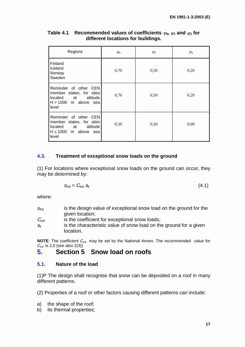
EN 1991-1-3:2003 (E)
17
Table 4.1 Recommended values of coefficients 0, 1 and 2 fordifferent locations for buildings.
Regions 0 1 2
FinlandIcelandNorwaySweden
0,70 0,50 0,20
Reminder of other CENmember states, for siteslocated at altitudeH > 1000 m above sealevel
0,70 0,50 0,20
Reminder of other CENmember states, for siteslocated at altitudeH 1000 m above sealevel
0,50 0,20 0,00
4.3. Treatment of exceptional snow loads on the ground
(1) For locations where exceptional snow loads on the ground can occur, theymay be determined by:
sAd = Cesl sk (4.1)
where:
sAd is the design value of exceptional snow load on the ground for thegiven location;
Cesl is the coefficient for exceptional snow loads;sk is the characteristic value of snow load on the ground for a given
location.
NOTE: The coefficient Cesl may be set by the National Annex. The recommended value forCesl is 2,0 (see also 2(3))
5. Section 5 Snow load on roofs
5.1. Nature of the load
(1)P The design shall recognise that snow can be deposited on a roof in manydifferent patterns.
(2) Properties of a roof or other factors causing different patterns can include:
a) the shape of the roof;b) its thermal properties;

EN 1991-1-3:2003 (E)
18
c) the roughness of its surface;d) the amount of heat generated under the roof;e) the proximity of nearby buildings;f) the surrounding terrain;g) the local meteorological climate, in particular its windiness, temperature
variations, and likelihood of precipitation (either as rain or as snow).
5.2. Load arrangements
(1)P The following two primary load arrangements shall be taken into account:
– undrifted snow load on roofs (see 1.6.5);– drifted snow load on roofs (see 1.6.6).
(2) The load arrangements should be determined using 5.3; and Annex B,where specified in accordance with 3.3.
NOTE: The National Annex may specify the use of Annex B for the roof shapes described in5.3.4, 5.3.6 and 6.2, and will normally apply to specific locations where all the snow usuallymelts and clears between the individual weather systems and where moderate to high windspeeds occur during the individual weather system.
(3)P Snow loads on roofs shall be determined as follows:
a) for the persistent / transient design situations
s = i Ce Ct sk (5.1)
b) for the accidental design situations where exceptional snow load is theaccidental action (except for the cases covered in 5.2 (3) P c)
s = i Ce Ct sAd (5.2)
Note : See 2(3).
c) for the accidental design situations where exceptional snow drift is theaccidental action and where Annex B applies
s = i sk (5.3)
NOTE: See 2(4).
where:
i is the snow load shape coefficient (see Section 5.3 and Annex B)
sk is the characteristic value of snow load on the ground
sAd is the design value of exceptional snow load on the ground for agiven location (see 4.3)

EN 1991-1-3:2003 (E)
19
Ce is the exposure coefficient
Ct is the thermal coefficient
(4) The load should be assumed to act vertically and refer to a horizontalprojection of the roof area.
(5) When artificial removal or redistribution of snow on a roof is anticipated theroof should be designed for suitable load arrangements.
NOTE 1: Load arrangements according to this Section have been derived for naturaldeposition patterns only.
NOTE 2: Further guidance may be given in the National Annex.
(6) In regions with possible rainfalls on the snow and consecutive melting andfreezing, snow loads on roofs should be increased, especially in cases wheresnow and ice can block the drainage system of the roof.
NOTE: Further complementary guidance may be given in the National Annex.
(7) The exposure coefficient Ce should be used for determining the snow loadon the roof. The choice for Ce should consider the future development aroundthe site. Ce should be taken as 1,0 unless otherwise specified for differenttopographies.
NOTE: The National Annex may give the values of Ce for different topographies. Therecommended values are given in Table 5.1 below.
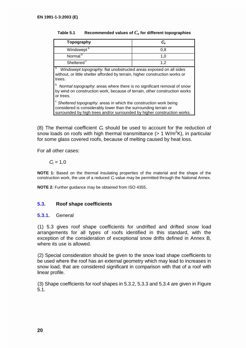
EN 1991-1-3:2003 (E)
20
Table 5.1 Recommended values of Ce for different topographies
Topography Ce
Windswept a 0,8
Normal b 1,0
Sheltered c 1,2a Windswept topography: flat unobstructed areas exposed on all sideswithout, or little shelter afforded by terrain, higher construction works ortrees.b Normal topography: areas where there is no significant removal of snowby wind on construction work, because of terrain, other construction worksor trees.c Sheltered topography: areas in which the construction work beingconsidered is considerably lower than the surrounding terrain orsurrounded by high trees and/or surrounded by higher construction works.
(8) The thermal coefficient Ct should be used to account for the reduction ofsnow loads on roofs with high thermal transmittance (> 1 W/m2K), in particularfor some glass covered roofs, because of melting caused by heat loss.
For all other cases:
Ct = 1,0
NOTE 1: Based on the thermal insulating properties of the material and the shape of theconstruction work, the use of a reduced Ct value may be permitted through the National Annex.
NOTE 2: Further guidance may be obtained from ISO 4355.
5.3. Roof shape coefficients
5.3.1. General
(1) 5.3 gives roof shape coefficients for undrifted and drifted snow loadarrangements for all types of roofs identified in this standard, with theexception of the consideration of exceptional snow drifts defined in Annex B,where its use is allowed.
(2) Special consideration should be given to the snow load shape coefficients tobe used where the roof has an external geometry which may lead to increases insnow load, that are considered significant in comparison with that of a roof withlinear profile.
(3) Shape coefficients for roof shapes in 5.3.2, 5.3.3 and 5.3.4 are given in Figure5.1.
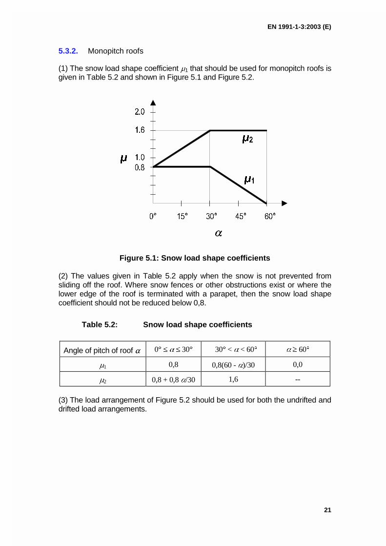
EN 1991-1-3:2003 (E)
21
5.3.2. Monopitch roofs
(1) The snow load shape coefficient 1 that should be used for monopitch roofs isgiven in Table 5.2 and shown in Figure 5.1 and Figure 5.2.
Figure 5.1: Snow load shape coefficients
(2) The values given in Table 5.2 apply when the snow is not prevented fromsliding off the roof. Where snow fences or other obstructions exist or where thelower edge of the roof is terminated with a parapet, then the snow load shapecoefficient should not be reduced below 0,8.
Table 5.2: Snow load shape coefficients
Angle of pitch of roof 0 30 30 < < 60 60
1 0,8 0,8(60 - )/30 0,0
2 0,8 + 0,8 /30 1,6 --
(3) The load arrangement of Figure 5.2 should be used for both the undrifted anddrifted load arrangements.
EN 1991-1-3:2003 (E)
22
Figure 5.2: Snow load shape coefficient - monopitch roof
5.3.3. Pitched roofs
(1) The snow load shape coefficients that should be used for pitched roofs aregiven in Figure 5.3, where 1 is given in Table 5.2 and shown in Figure 5.1.
(2) The values given in Table 5.2 apply when snow is not prevented fromsliding off the roof. Where snow fences or other obstructions exist or where thelower edge of the roof is terminated with a parapet, then the snow load shapecoefficient should not be reduced below 0,8.
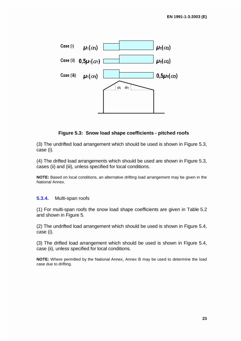
EN 1991-1-3:2003 (E)
23
Figure 5.3: Snow load shape coefficients - pitched roofs
(3) The undrifted load arrangement which should be used is shown in Figure 5.3,case (i).
(4) The drifted load arrangements which should be used are shown in Figure 5.3,cases (ii) and (iii), unless specified for local conditions.
NOTE: Based on local conditions, an alternative drifting load arrangement may be given in theNational Annex.
5.3.4. Multi-span roofs
(1) For multi-span roofs the snow load shape coefficients are given in Table 5.2and shown in Figure 5.
(2) The undrifted load arrangement which should be used is shown in Figure 5.4,case (i).
(3) The drifted load arrangement which should be used is shown in Figure 5.4,case (ii), unless specified for local conditions.
NOTE: Where permitted by the National Annex, Annex B may be used to determine the loadcase due to drifting.
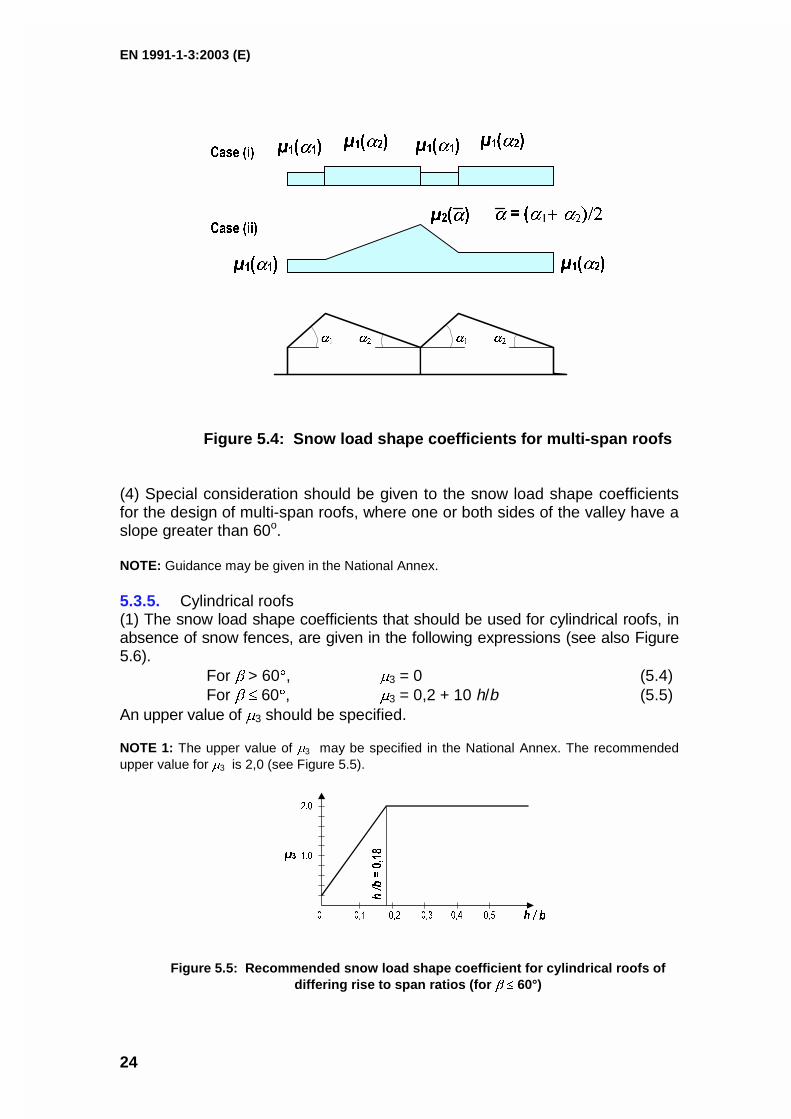
EN 1991-1-3:2003 (E)
24
Figure 5.4: Snow load shape coefficients for multi-span roofs
(4) Special consideration should be given to the snow load shape coefficientsfor the design of multi-span roofs, where one or both sides of the valley have aslope greater than 60o.
NOTE: Guidance may be given in the National Annex.
5.3.5. Cylindrical roofs(1) The snow load shape coefficients that should be used for cylindrical roofs, inabsence of snow fences, are given in the following expressions (see also Figure5.6).
For > 60, 3 = 0 (5.4)For 60, 3 = 0,2 + 10 h/b (5.5)
An upper value of 3 should be specified.
NOTE 1: The upper value of 3 may be specified in the National Annex. The recommendedupper value for 3 is 2,0 (see Figure 5.5).
Figure 5.5: Recommended snow load shape coefficient for cylindrical roofs ofdiffering rise to span ratios (for 60°)
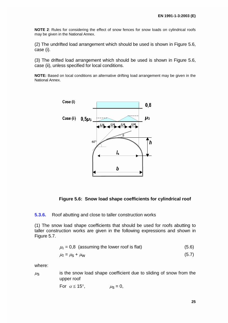
EN 1991-1-3:2003 (E)
25
NOTE 2: Rules for considering the effect of snow fences for snow loads on cylindrical roofsmay be given in the National Annex.
(2) The undrifted load arrangement which should be used is shown in Figure 5.6,case (i).
(3) The drifted load arrangement which should be used is shown in Figure 5.6,case (ii), unless specified for local conditions.
NOTE: Based on local conditions an alternative drifting load arrangement may be given in theNational Annex.
ls/4
ls/4 ls/4 ls/4
Figure 5.6: Snow load shape coefficients for cylindrical roof
5.3.6. Roof abutting and close to taller construction works
(1) The snow load shape coefficients that should be used for roofs abutting totaller construction works are given in the following expressions and shown inFigure 5.7.
1 = 0,8 (assuming the lower roof is flat) (5.6)
2 = s + w (5.7)
where:
s is the snow load shape coefficient due to sliding of snow from theupper roof
For 15, s = 0,
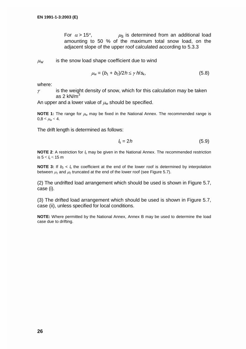
EN 1991-1-3:2003 (E)
26
For > 15, s is determined from an additional loadamounting to 50 % of the maximum total snow load, on theadjacent slope of the upper roof calculated according to 5.3.3
w is the snow load shape coefficient due to wind
w = (b1 + b2)/2h h/sk, (5.8)
where: is the weight density of snow, which for this calculation may be taken
as 2 kN/m3
An upper and a lower value of w should be specified.
NOTE 1: The range for w may be fixed in the National Annex. The recommended range is0,8 w 4.
The drift length is determined as follows:
ls = 2h (5.9)
NOTE 2: A restriction for ls may be given in the National Annex. The recommended restrictionis 5 ls 15 m
NOTE 3: If b2 < ls the coefficient at the end of the lower roof is determined by interpolationbetween 1 and 2 truncated at the end of the lower roof (see Figure 5.7).
(2) The undrifted load arrangement which should be used is shown in Figure 5.7,case (i).
(3) The drifted load arrangement which should be used is shown in Figure 5.7,case (ii), unless specified for local conditions.
NOTE: Where permitted by the National Annex, Annex B may be used to determine the loadcase due to drifting.
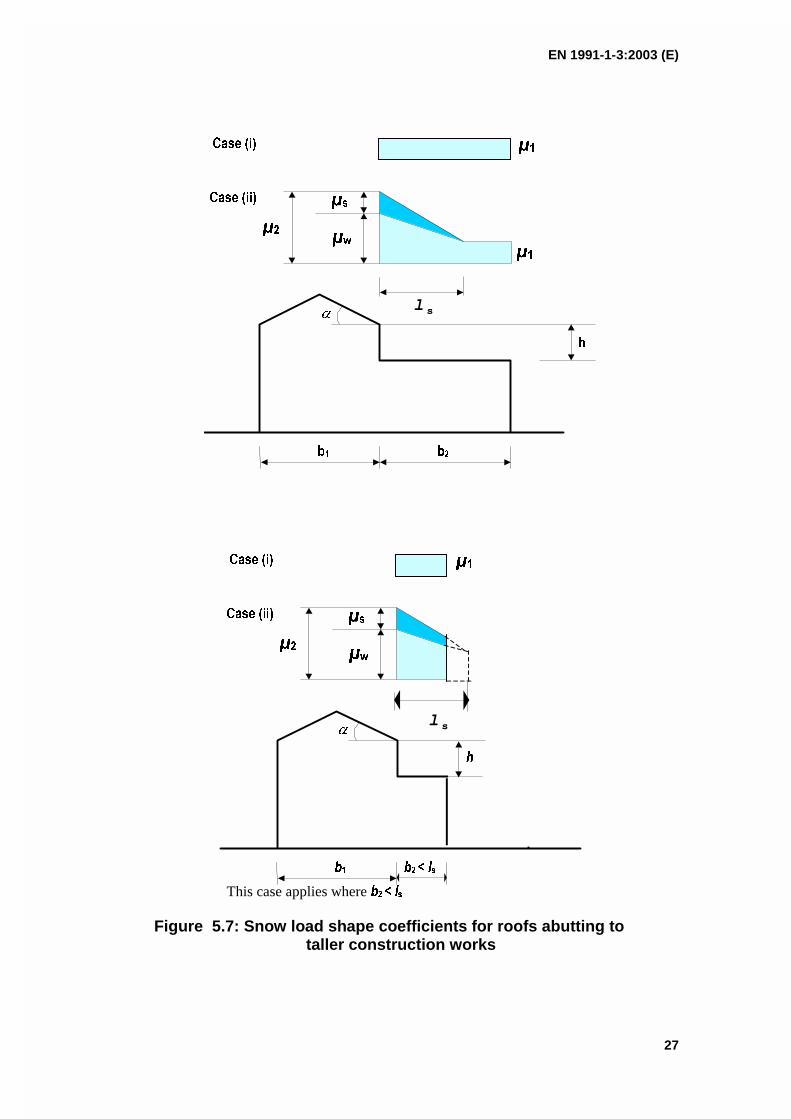
EN 1991-1-3:2003 (E)
27
l s
l s
This case applies where
Figure 5.7: Snow load shape coefficients for roofs abutting totaller construction works
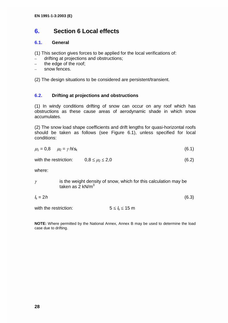
EN 1991-1-3:2003 (E)
28
6. Section 6 Local effects
6.1. General
(1) This section gives forces to be applied for the local verifications of:– drifting at projections and obstructions;– the edge of the roof;– snow fences.
(2) The design situations to be considered are persistent/transient.
6.2. Drifting at projections and obstructions
(1) In windy conditions drifting of snow can occur on any roof which hasobstructions as these cause areas of aerodynamic shade in which snowaccumulates.
(2) The snow load shape coefficients and drift lengths for quasi-horizontal roofsshould be taken as follows (see Figure 6.1), unless specified for localconditions:
1 = 0,8 2 = h/sk (6.1)
with the restriction: 0,8 2 2,0 (6.2)
where:
is the weight density of snow, which for this calculation may betaken as 2 kN/m3
ls = 2h (6.3)
with the restriction: 5 ls 15 m
NOTE: Where permitted by the National Annex, Annex B may be used to determine the loadcase due to drifting.
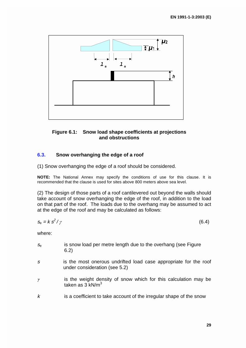
EN 1991-1-3:2003 (E)
29
Figure 6.1: Snow load shape coefficients at projectionsand obstructions
6.3. Snow overhanging the edge of a roof
(1) Snow overhanging the edge of a roof should be considered.
NOTE: The National Annex may specify the conditions of use for this clause. It isrecommended that the clause is used for sites above 800 meters above sea level.
(2) The design of those parts of a roof cantilevered out beyond the walls shouldtake account of snow overhanging the edge of the roof, in addition to the loadon that part of the roof. The loads due to the overhang may be assumed to actat the edge of the roof and may be calculated as follows:
se = k s2 / (6.4)
where:
se is snow load per metre length due to the overhang (see Figure 6.2)
s is the most onerous undrifted load case appropriate for the roofunder consideration (see 5.2)
is the weight density of snow which for this calculation may betaken as 3 kN/m3
k is a coefficient to take account of the irregular shape of the snow
l s
l s
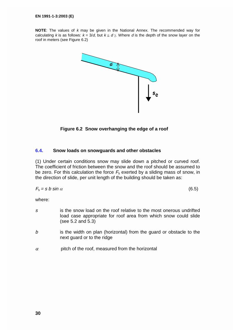
EN 1991-1-3:2003 (E)
30
NOTE: The values of k may be given in the National Annex. The recommended way forcalculating k is as follows: k = 3/d, but k d . Where d is the depth of the snow layer on theroof in meters (see Figure 6.2)
d
Figure 6.2 Snow overhanging the edge of a roof
6.4. Snow loads on snowguards and other obstacles
(1) Under certain conditions snow may slide down a pitched or curved roof.The coefficient of friction between the snow and the roof should be assumed tobe zero. For this calculation the force Fs exerted by a sliding mass of snow, inthe direction of slide, per unit length of the building should be taken as:
Fs = s b sin (6.5)
where:
s is the snow load on the roof relative to the most onerous undriftedload case appropriate for roof area from which snow could slide(see 5.2 and 5.3)
b is the width on plan (horizontal) from the guard or obstacle to thenext guard or to the ridge
pitch of the roof, measured from the horizontal

EN 1991-1-3:2003 (E)
31
ANNEX A(normative)
Design situations and load arrangements to be usedfor different locations
(1) Table A.1 summarises four cases A, B1, B2 and B3 (see 3.2, 3.3(1), 3.3(2)and 3.3(3) respectively) identifying the design situations and loadarrangements to be used for each individual case.

EN 1991-1-3:2003 (E)
32
Table A.1 Design Situations and load arrangements to be used for different locations
Normal Exceptional conditionsCase A Case B1 Case B2 Case B3No exceptional fallsNo exceptional drift
Exceptional fallsNo exceptional drift
No exceptional fallsExceptional drift
Exceptional fallsExceptional drift
3.2(1) 3.3(1) 3.3(2) 3.3(3)
Persistent/transient designsituation
[1] undrifted i CeCt sk
[2] drifted i CeCt sk
Persistent/transient designsituation
[1] undrifted i CeCt sk
[2] drifted i CeCt sk
Accidental design situation(where snow is the accidentalaction)
[3] undrifted i CeCt Cesl sk
[4] drifted i CeCt Cesl sk
Persistent/transient designsituation
[1] undrifted i CeCt sk
[2] drifted i CeCt sk (except forroof shapes in AnnexB)
Accidental design situation(where snow is the accidentalaction)
[3] drifted i sk (for roof shapesin AnnexB)
Persistent/transient designsituation
[1] undrifted i CeCt sk
[2] drifted i CeCt sk (except forroof shapes in AnnexB)
Accidental design situation(where snow is the accidentalaction)
[3] undrifted i CeCt Cesl sk
[4] drifted i sk (for roof shapesin AnnexB)
NOTE 1: Exceptional conditions are defined according to the National Annex.
NOTE 2: For cases B1 and B3 the National Annex may define design situations which apply for the particular local effects described in section 6.
EN 1991-1-3:2003 (E)
33
ANNEX B(normative)
Snow load shape coefficients for exceptional snowdrifts
B1 Scope
(1) This annex gives snow shape coefficients to determine load arrangementsdue to exceptional snow drifts for the following types of roofs.a) Multi-span roofs;b) Roofs abutting and close to taller construction works;c) Roofs where drifting occurs at projections, obstructions and parapets.d) For all other load arrangements Section 5 and Section 6 should be used
as appropriate.
(2) When considering load cases using snow load shape coefficients obtainedfrom this Annex it should be assumed that they are exceptional snow driftloads and that there is no snow elsewhere on the roof.
(3) In some circumstances more than one drift load case may be applicable forthe same location on a roof in which case they should be treated asalternatives.
B2 Multi-span roofs
(1) The snow load shape coefficient for an exceptional snow drift that shouldbe used for valleys of multi-span roofs is given in Figure B1 and B2(2).
Figure B1: Shape coefficient and drift lengths for exceptional snow drifts– valleys of multi-span roofs
h
b2b1
b3
ls2ls1
1
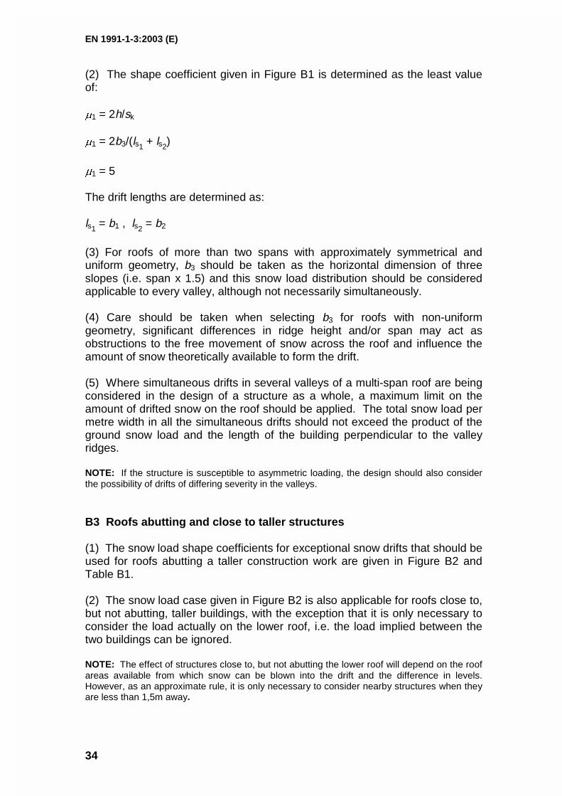
EN 1991-1-3:2003 (E)
34
(2) The shape coefficient given in Figure B1 is determined as the least valueof:
1 = 2h/sk
1 = 2b3/(ls1 + ls2)
1 = 5
The drift lengths are determined as:
ls1 = b1 , ls2 = b2
(3) For roofs of more than two spans with approximately symmetrical anduniform geometry, b3 should be taken as the horizontal dimension of threeslopes (i.e. span x 1.5) and this snow load distribution should be consideredapplicable to every valley, although not necessarily simultaneously.
(4) Care should be taken when selecting b3 for roofs with non-uniformgeometry, significant differences in ridge height and/or span may act asobstructions to the free movement of snow across the roof and influence theamount of snow theoretically available to form the drift.
(5) Where simultaneous drifts in several valleys of a multi-span roof are beingconsidered in the design of a structure as a whole, a maximum limit on theamount of drifted snow on the roof should be applied. The total snow load permetre width in all the simultaneous drifts should not exceed the product of theground snow load and the length of the building perpendicular to the valleyridges.
NOTE: If the structure is susceptible to asymmetric loading, the design should also considerthe possibility of drifts of differing severity in the valleys.
B3 Roofs abutting and close to taller structures
(1) The snow load shape coefficients for exceptional snow drifts that should beused for roofs abutting a taller construction work are given in Figure B2 andTable B1.
(2) The snow load case given in Figure B2 is also applicable for roofs close to,but not abutting, taller buildings, with the exception that it is only necessary toconsider the load actually on the lower roof, i.e. the load implied between thetwo buildings can be ignored.
NOTE: The effect of structures close to, but not abutting the lower roof will depend on the roofareas available from which snow can be blown into the drift and the difference in levels.However, as an approximate rule, it is only necessary to consider nearby structures when theyare less than 1,5m away.
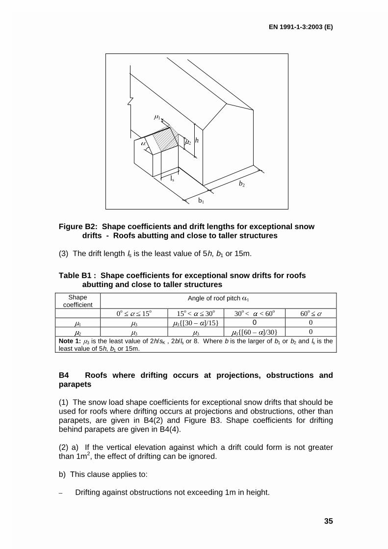
EN 1991-1-3:2003 (E)
35
Figure B2: Shape coefficients and drift lengths for exceptional snowdrifts - Roofs abutting and close to taller structures
(3) The drift length ls is the least value of 5h, b1 or 15m.
Table B1 : Shape coefficients for exceptional snow drifts for roofsabutting and close to taller structures
Shapecoefficient
Angle of roof pitch 1
0o 15o 15o < 30o 30o < < 60o 60o
1 3 3[30 – ]/15 0 02 3 3 3[60 – ]/30 0
Note 1: 3 is the least value of 2h/sK , 2b/ls or 8. Where b is the larger of b1 or b2 and ls is theleast value of 5h, b1 or 15m.
B4 Roofs where drifting occurs at projections, obstructions andparapets
(1) The snow load shape coefficients for exceptional snow drifts that should beused for roofs where drifting occurs at projections and obstructions, other thanparapets, are given in B4(2) and Figure B3. Shape coefficients for driftingbehind parapets are given in B4(4).
(2) a) If the vertical elevation against which a drift could form is not greaterthan 1m2, the effect of drifting can be ignored.
b) This clause applies to:
– Drifting against obstructions not exceeding 1m in height.
ls
1
2h
b1
b2
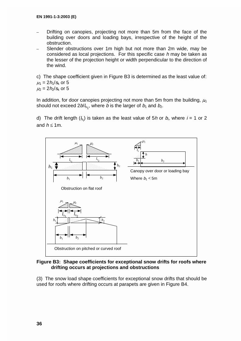
EN 1991-1-3:2003 (E)
36
– Drifting on canopies, projecting not more than 5m from the face of thebuilding over doors and loading bays, irrespective of the height of theobstruction.
– Slender obstructions over 1m high but not more than 2m wide, may beconsidered as local projections. For this specific case h may be taken asthe lesser of the projection height or width perpendicular to the direction ofthe wind.
c) The shape coefficient given in Figure B3 is determined as the least value of:1 = 2h1/sk or 52 = 2h2/sk or 5
In addition, for door canopies projecting not more than 5m from the building, 1
should not exceed 2b/ls1, where b is the larger of b1 and b2.
d) The drift length (lsi) is taken as the least value of 5h or bi, where i = 1 or 2
and h 1m.
Figure B3: Shape coefficients for exceptional snow drifts for roofs wheredrifting occurs at projections and obstructions
(3) The snow load shape coefficients for exceptional snow drifts that should beused for roofs where drifting occurs at parapets are given in Figure B4.
h1
Obstruction on flat roof
2
ls2ls1
1
h2
b2b1
b1 b2
h2h1
ls1 ls2
1 2
Obstruction on pitched or curved roof
b1 b2
lsh
1
Canopy over door or loading bay
Where b1 5m
EN 1991-1-3:2003 (E)
37
Figure B4 : Shape coefficients for exceptional snow drifts - roofs wheredrifting occurs at parapets
(4) The shape coefficient given in Figure B4 is determined as the least valueof:
1 = 2h/sk ,
1 = 2b/ls where b is the larger of b1 or b2
1 = 8
The drift length ls should be taken as the least value of 5h, b1 or 15m.
(5) For drifting in a valley behind a parapet at a gable end the snow load at theface of the parapet should be assumed to decrease linearly from its maximumvalue in the valley to zero at the adjacent ridges, providing the parapet doesnot project more than 300mm above the ridge.
h
b1
ls
1
Snow behind parapet;flat roof
h
lsSnow in valley behindparapet at gable end
b1
1
Ridge line
Gutter line
b2
1
b1
lsSnow behind parapet at eaves;
pitched or curved roof
NOTE: b2 shouldbe used in thecalculation of shapecoefficient
h
EN 1991-1-3:2003 (E)
38
ANNEX C(informative)
European Ground Snow Load Maps
(1) This Annex presents the European snow maps which are the result ofscientific work carried out under contract to DGIII/D-35 of the EuropeanCommission, by a specifically formed research Group.
NOTE: The snow maps supplied by CEN members who were not directly part of the ResearchGroup have been included in this Annex in clauses C(5) Czech Republic, C(6) Iceland andC(7) Poland.
(2) The objectives of this Annex, defined in 1.1(5), are:– to help National Competent Authorities to redraft their national maps;– to establish harmonised procedures to produce the maps.
This will eliminate or reduce the inconsistencies of snow load values in CENmember states and at borderlines between countries.
(3) The European snow map developed by the Research Group are dividedinto 9 different homogeneous climatic regions, as shown in Figures C.1 toC.10.
(4) In each climatic region a given load-altitude correlation formula applies andthis is given in Table C.1.Different zones are defined for each climatic region. Each zone is given a Zonenumber Z, which is used in the load altitude correction formula.Among the research Group members only for Norway the map gives directlysnow load on the ground at different locations.The characteristic values of ground snow loads given are referred to meanrecurrence interval (MRI) equal to 50 years.
(5) Figure C.11 shows the map supplied by the Czech National Authority.
(6) Figure C.12 shows the map supplied by the Icelandic National Authority.
5 Results are included in the following documents, both of them are available at the
Commission of the European Communities DG III - D-3 Industry, Rue de la Loi, 200 B -1049 Brussels, or at the Università degli Studi di Pisa Dipartimento di Ingegneria Strutturale,Via Diotisalvi, 2, 56100 Pisa (IT).1. Phase 1 Final Report to the European Commission, Scientific Support Activity in theField of Structural Stability of Civil Engineering Works: Snow Loads, Department ofStructural Engineering, University of Pisa, March 1998.2. Phase 2 Final Report to the European Commission, Scientific Support Activity in theField of Structural Stability of Civil Engineering Works: Snow Loads, Department ofStructural Engineering, University of Pisa, September 1999.
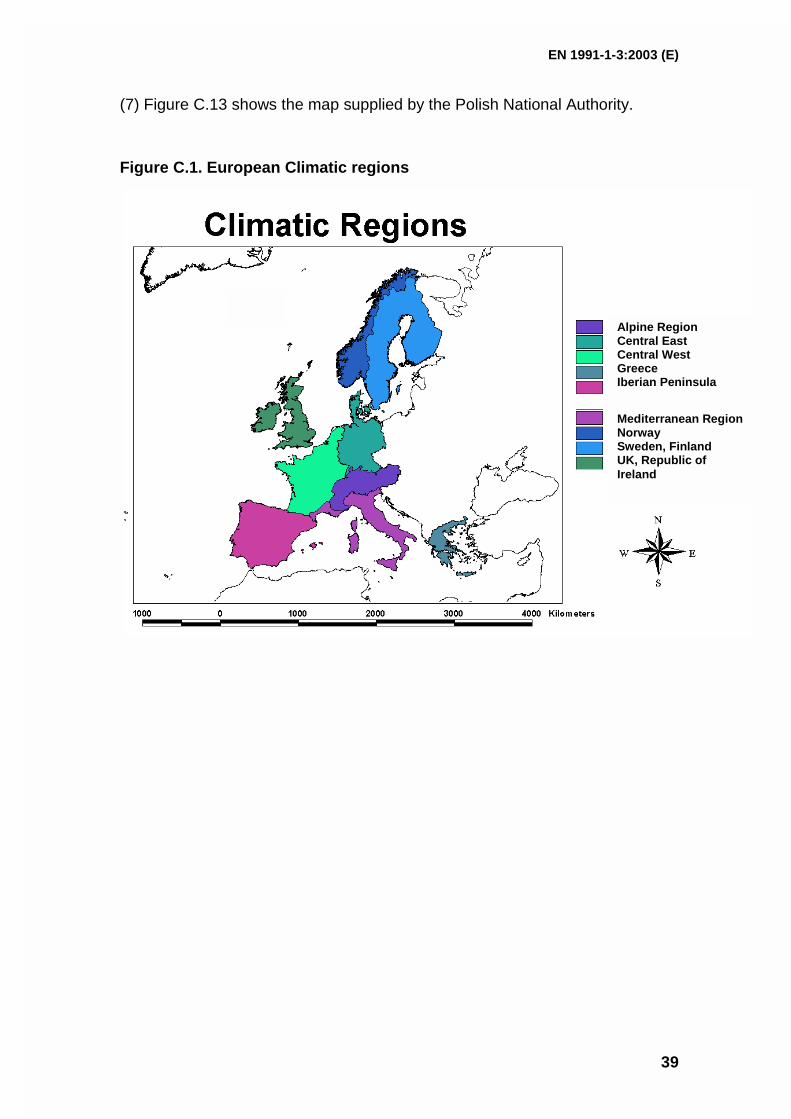
EN 1991-1-3:2003 (E)
39
(7) Figure C.13 shows the map supplied by the Polish National Authority.
Figure C.1. European Climatic regions
Alpine RegionCentral EastCentral WestGreeceIberian Peninsula
Mediterranean RegionNorwaySweden, FinlandUK, Republic ofIreland
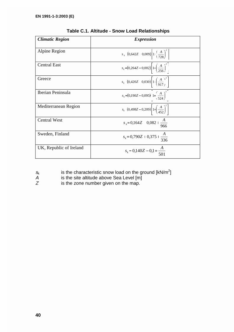
EN 1991-1-3:2003 (E)
40
Table C.1. Altitude - Snow Load Relationships
Climatic Region Expression
Alpine Region
2
7281009,0642,0
AZsk
Central East
2
2561002,0264,0
AZsk
Greece
2
9171030,0420,0
AZsk
Iberian Peninsula
2
5241095,0190,0
AZsk
Mediterranean Region
2
4521209,0498,0
AZsk
Central West966
082,0164,0A
Zsk
Sweden, Finland336
375,0790,0A
Zsk
UK, Republic of Ireland501
1,0140,0A
Zsk
sk is the characteristic snow load on the ground [kN/m2]A is the site altitude above Sea Level [m]Z is the zone number given on the map.
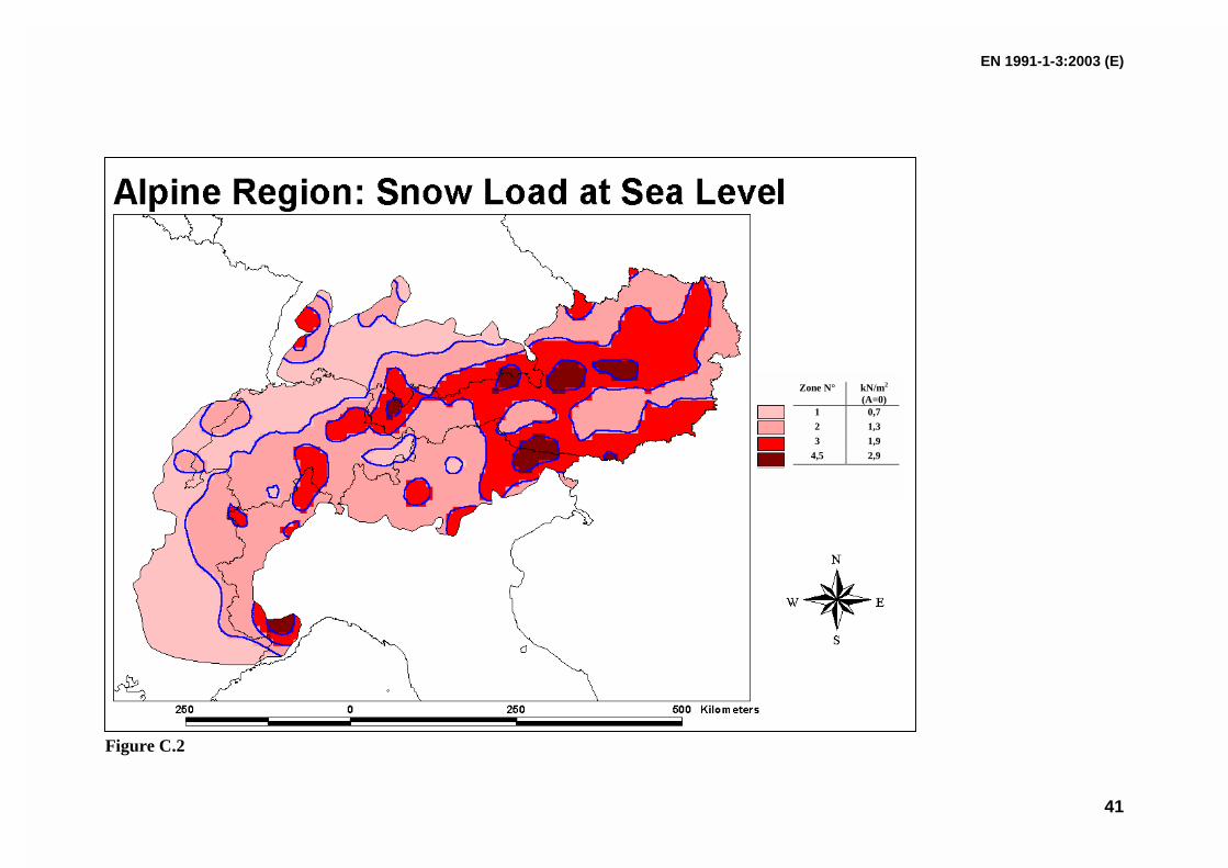
EN 1991-1-3:2003 (E)
41
Figure C.2
Zone N° kN/m2
(A=0)1 0,72 1,33 1,9
4,5 2,9
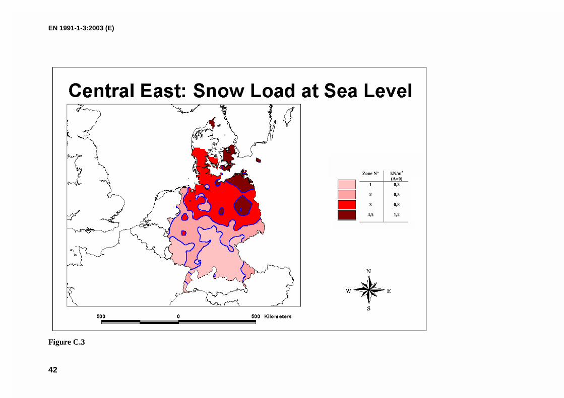
EN 1991-1-3:2003 (E)
42
Figure C.3
Zone N° kN/m2
(A=0)1 0,3
2 0,5
3 0,8
4,5 1,2
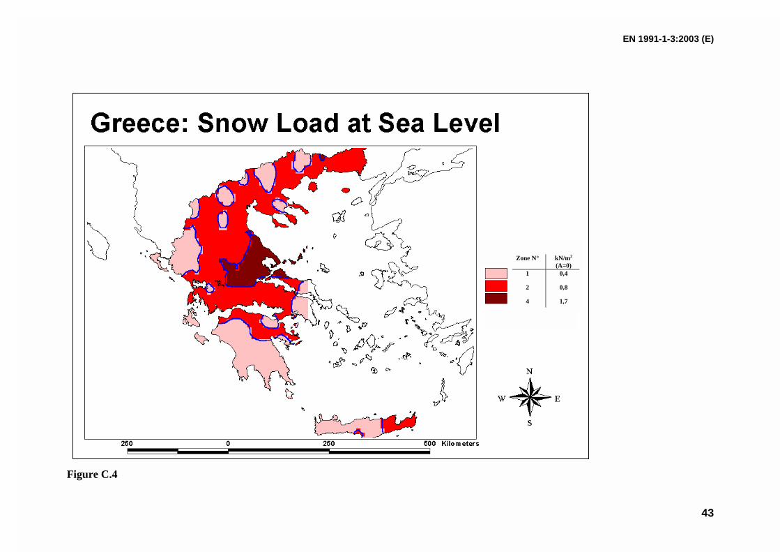
EN 1991-1-3:2003 (E)
43
Figure C.4
Zone N° kN/m2
(A=0)1 0,4
2 0,8
4 1,7
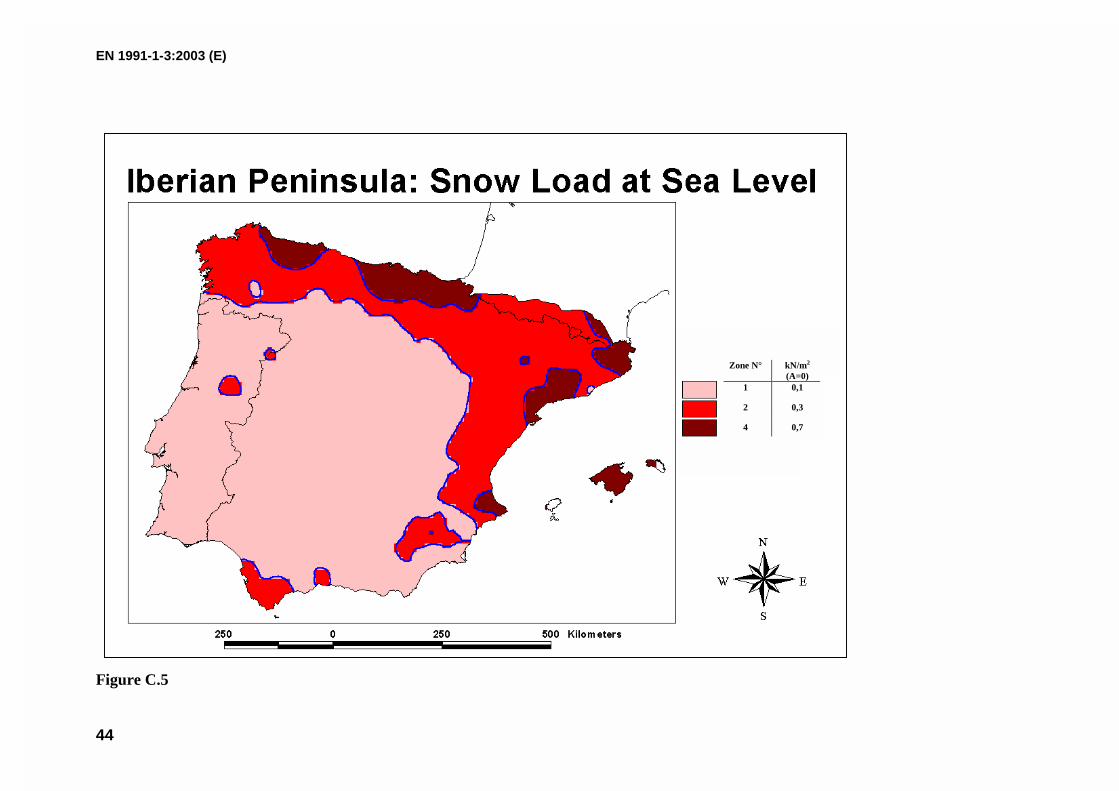
EN 1991-1-3:2003 (E)
44
Figure C.5
Zone N° kN/m2
(A=0)1 0,1
2 0,3
4 0,7
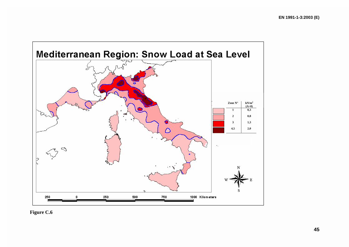
EN 1991-1-3:2003 (E)
45
Figure C.6
Zone N° kN/m2
(A=0)1 0,3
2 0,8
3 1,3
4,5 2,0
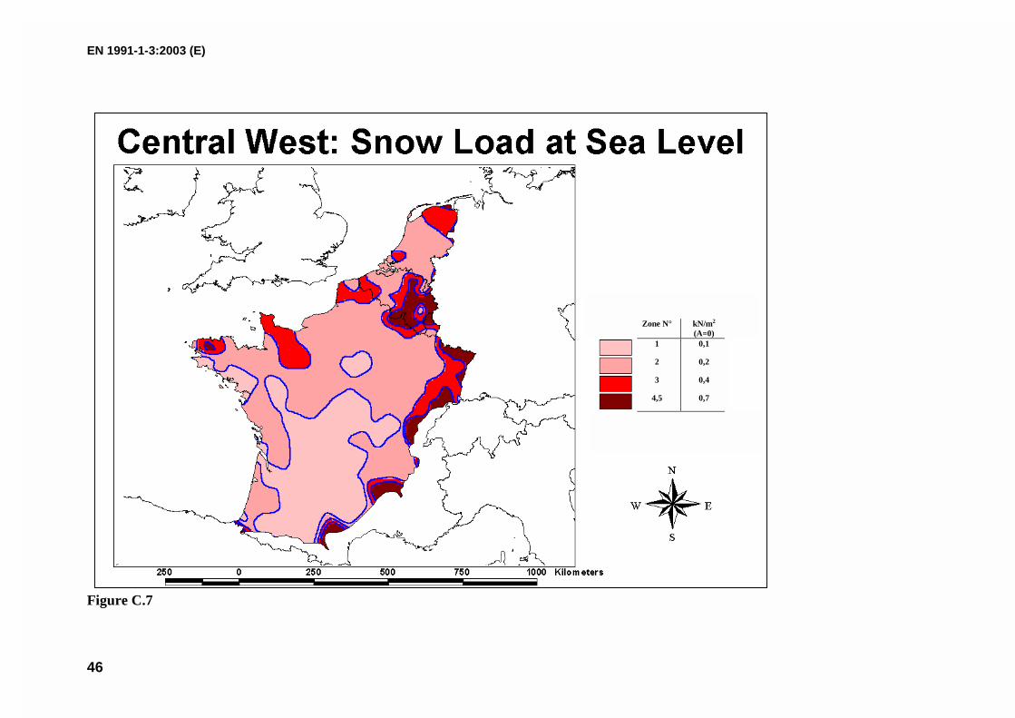
EN 1991-1-3:2003 (E)
46
Figure C.7
Zone N° kN/m2
(A=0)1 0,1
2 0,2
3 0,4
4,5 0,7
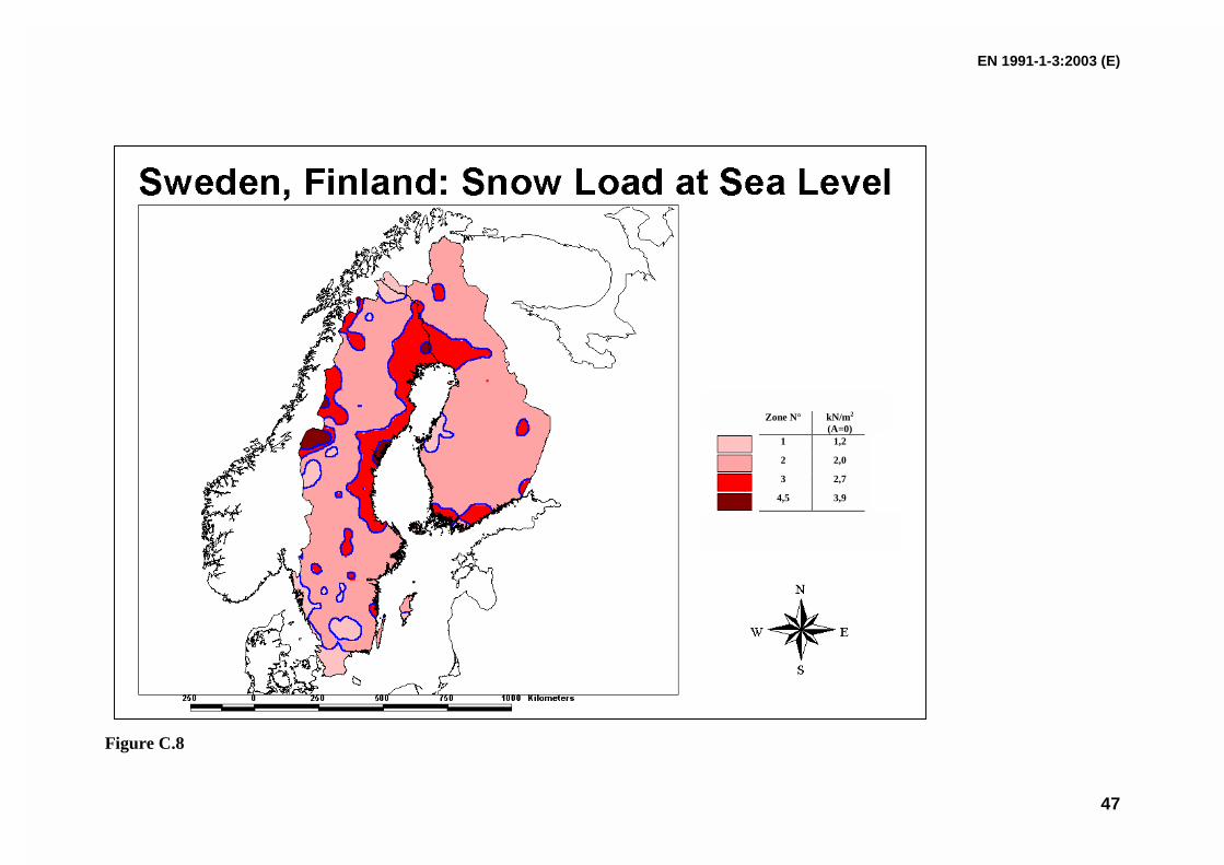
EN 1991-1-3:2003 (E)
47
Figure C.8
Zone N° kN/m2
(A=0)1 1,2
2 2,0
3 2,7
4,5 3,9
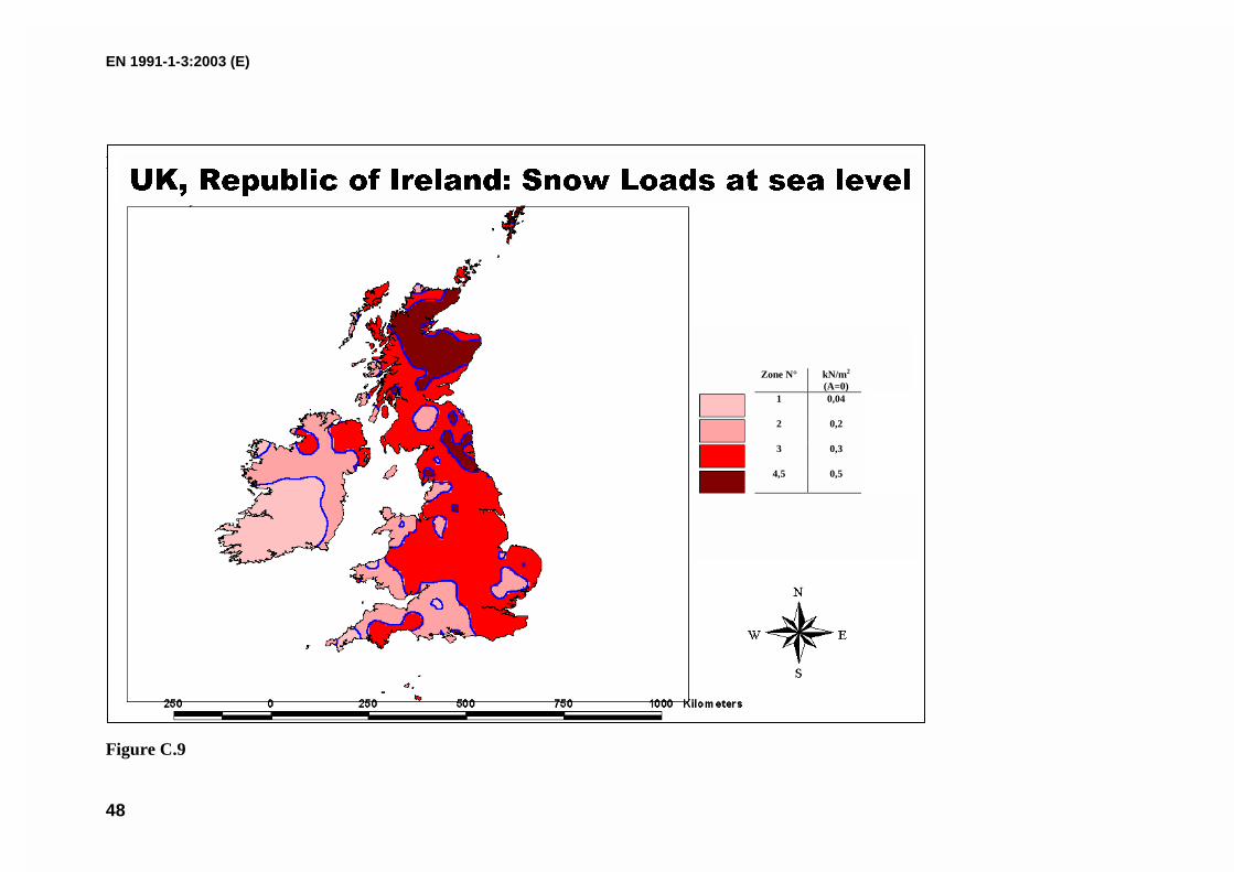
EN 1991-1-3:2003 (E)
48
Figure C.9
Figure C.9
Zone N° kN/m2
(A=0)1 0,04
2 0,2
3 0,3
4,5 0,5
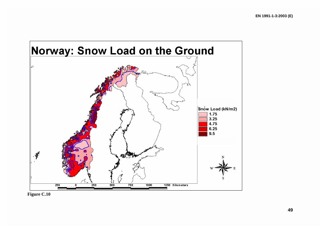
EN 1991-1-3:2003 (E)
49
Figure C.10

EN 1991-1-3:2003 (E)
50
Czech Republic: Snow Load on the ground
Figure C.11

EN 1991-1-3:2003 (E)
51
Snow Map of Iceland
Figure C.12

EN 1991-1-3:2003 (E)
52
Snow Map of Poland
Zone sk, kN/m2
1 0,007A – 1,4; sk 0,702 0,93 0,006A – 0,6; sk 1,24 1,65 0,93exp(0,00134A); sk 2,0
NOTE: A = Site altitude above sea level (m)
Figure C.13
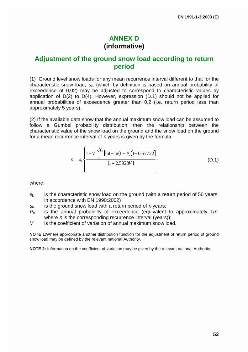
EN 1991-1-3:2003 (E)
53
ANNEX D(informative)
Adjustment of the ground snow load according to returnperiod
(1) Ground level snow loads for any mean recurrence interval different to that for thecharacteristic snow load, sk, (which by definition is based on annual probability ofexceedence of 0,02) may be adjusted to correspond to characteristic values byapplication of D(2) to D(4). However, expression (D.1) should not be applied forannual probabilities of exceedence greater than 0,2 (i.e. return period less thanapproximately 5 years).
(2) If the available data show that the annual maximum snow load can be assumed tofollow a Gumbel probability distribution, then the relationship between thecharacteristic value of the snow load on the ground and the snow load on the groundfor a mean recurrence interval of n years is given by the formula:
(D.1)
where:
sk is the characteristic snow load on the ground (with a return period of 50 years,in accordance with EN 1990:2002)
sn is the ground snow load with a return period of n years;Pn is the annual probability of exceedence (equivalent to approximately 1/n,
where n is the corresponding recurrence interval (years));V is the coefficient of variation of annual maximum snow load.
NOTE 1:Where appropriate another distribution function for the adjustment of return period of groundsnow load may be defined by the relevant national Authority.
NOTE 2: Information on the coefficient of variation may be given by the relevant national Authority.
V
PVss
n
kn 5923,21
57722,01lnln6
1
EN 1991-1-3:2003 (E)
54
(3) Expression (D.1) is shown graphically in Figure D.1.
0,8
0,85
0,9
0,95
1
1,05
1,1
1,15
20 30 40 50 60 70 80 90 100
Return period in years
s n/s k
V =0.6
V =0.2
Figure D.1 Adjustment of the ground snow load according to return period
(4) Where permitted by the relevant national Authority expression (D.1) may also beadapted to calculate snow loads on the ground for other probabilities of exceedence.For example for:
a) structures where a higher risk of exceedence is deemed acceptableb) structures where greater than normal safety is required

EN 1991-1-3:2003 (E)
55
ANNEX E(informative)
Bulk weight density of snow
(1) The bulk weight density of snow varies. In general it increases with the duration of thesnow cover and depends on the site location, climate and altitude.
(2) Except where specified in Sections 1 to 6 indicative values for the mean bulk weightdensity of snow on the ground given in Table E.1 may be used.
Table E.1: Mean bulk weight density of snow
Type of snow Bulk weight density [kN/m3]
Fresh 1,0
Settled (several hours or days after its fall) 2,0
Old (several weeks or months after its fall) 2,5 - 3,5
Wet 4,0

EN 1991-1-3:2003 (E)
56
Bibliography
ISO 4355 Bases for design of structures – Determination of snowloads on roofs
ISO 3898 Bases for design of structures - Notations – General symbols

EUROPEAN STANDARD
NORME EUROPÉENNE
EUROPÄISCHE NORM
FINAL DRAFTprEN 1991-1-4
January 2004
ICS 91.010.30 Will supersede ENV 1991-2-4:1995
English version
Eurocode 1: Actions on structures - General actions - Part 1-4:Wind actions
Eurocode 1 - Actions sur les structures - Partie 1-4 :Actions générales - Actions du vent
Eurocode 1: Einwirkungen auf Tragwerke - Teil 1-4:Allgemeine Einwirkungen - Windlasten
This draft European Standard is submitted to CEN members for formal vote. It has been drawn up by the Technical Committee CEN/TC250.
If this draft becomes a European Standard, CEN members are bound to comply with the CEN/CENELEC Internal Regulations whichstipulate the conditions for giving this European Standard the status of a national standard without any alteration.
This draft European Standard was established by CEN in three official versions (English, French, German). A version in any otherlanguage made by translation under the responsibility of a CEN member into its own language and notified to the Management Centre hasthe same status as the official versions.
CEN members are the national standards bodies of Austria, Belgium, Cyprus, Czech Republic, Denmark, Estonia, Finland, France,Germany, Greece, Hungary, Iceland, Ireland, Italy, Latvia, Lithuania, Luxembourg, Malta, Netherlands, Norway, Poland, Portugal, Slovakia,Slovenia, Spain, Sweden, Switzerland and United Kingdom.
Warning : This document is not a European Standard. It is distributed for review and comments. It is subject to change without notice andshall not be referred to as a European Standard.
EUROPEAN COMMITTEE FOR STANDARDIZATIONC OM ITÉ EUR OP ÉEN DE NOR M ALIS AT IONEUROPÄISCHES KOMITEE FÜR NORMUNG
Management Centre: rue de Stassart, 36 B-1050 Brussels
© 2004 CEN All rights of exploitation in any form and by any means reservedworldwide for CEN national Members.
Ref. No. prEN 1991-1-4:2004: E

Page 2 prEN 1991-1-4:2004
Contents Page
Foreword......................................................................................................................................................................5 Section 1 General ....................................................................................................................................................9 1.1 Scope ..............................................................................................................................................................9 1.2 Normative references ..................................................................................................................................10 1.3 Assumptions ................................................................................................................................................10 1.4 Distinction between Principles and Application Rules............................................................................10 1.5 Design assisted by testing and measurements .......................................................................................10 1.6 Definitions ....................................................................................................................................................10 1.7 Symbols ........................................................................................................................................................11 Section 2 Design situations .................................................................................................................................16 Section 3 Modelling of wind actions ...................................................................................................................16 3.1 Nature............................................................................................................................................................16 3.2 Representations of wind actions ...............................................................................................................16 3.3 Classification of wind actions ....................................................................................................................16 3.4 Characteristic values...................................................................................................................................16 3.5 Models...........................................................................................................................................................17 Section 4 Wind velocity and velocity pressure ..................................................................................................18 4.1 Basis for calculation....................................................................................................................................18 4.2 Basic values .................................................................................................................................................18 4.3 Mean wind.....................................................................................................................................................19 4.3.1 Variation with height....................................................................................................................................19 4.3.2 Terrain roughness .......................................................................................................................................19 4.3.3 Terrain orography ........................................................................................................................................21 4.3.4 Large and considerably higher neighbouring structures........................................................................21 4.3.5 Closely spaced buildings and obstacles...................................................................................................22 4.4 Wind turbulence...........................................................................................................................................22 4.5 Peak velocity pressure ................................................................................................................................22 Section 5 Wind actions .........................................................................................................................................24 5.1 General..........................................................................................................................................................24 5.2 Wind pressure on surfaces.........................................................................................................................24 5.3 Wind forces ..................................................................................................................................................25 Section 6 Structural factor cscd ...........................................................................................................................28 6.1 General..........................................................................................................................................................28 6.2 Determination of cscd ..................................................................................................................................28 6.3 Detailed procedure ......................................................................................................................................28 6.3.1 Structural factor cscd ...................................................................................................................................28 6.3.2 Serviceability assessments ........................................................................................................................30 6.3.3 Wake buffeting .............................................................................................................................................30 Section 7 Pressure and force coefficients..........................................................................................................31 7.1 General..........................................................................................................................................................31 7.1.1 Choice of aerodynamic coefficient ............................................................................................................31 7.1.2 Asymmetric and counteracting pressures and forces ............................................................................32 7.1.3 Effects of ice and snow...............................................................................................................................32 7.2 Pressure coefficients for buildings............................................................................................................33 7.2.1 General..........................................................................................................................................................33 7.2.2 Vertical walls of rectangular plan buildings..............................................................................................34 7.2.3 Flat roofs.......................................................................................................................................................37 7.2.4 Monopitch roofs...........................................................................................................................................40 7.2.5 Duopitch roofs .............................................................................................................................................43 7.2.6 Hipped roofs.................................................................................................................................................47 7.2.7 Multispan roofs ............................................................................................................................................48
Page 3 prEN 1991-1-4:2004
7.2.8 Vaulted roofs and domes............................................................................................................................50 7.2.9 Internal pressure..........................................................................................................................................51 7.2.10 Pressure on walls or roofs with more than one skin ...............................................................................54 7.3 Canopy roofs................................................................................................................................................55 7.4 Free-standing walls, parapets, fences and signboards...........................................................................62 7.4.1 Free-standing walls and parapets..............................................................................................................62 7.4.2 Shelter factors for walls, fences and parapets .........................................................................................64 7.4.3 Signboards ...................................................................................................................................................64 7.5 Friction coefficients.....................................................................................................................................65 7.6 Structural elements with rectangular sections.........................................................................................67 7.7 Structural elements with sharp edged section.........................................................................................68 7.8 Structural elements with regular polygonal section ................................................................................69 7.9 Circular cylinders ........................................................................................................................................71 7.9.1 External pressure coefficients ...................................................................................................................71 7.9.2 Force coefficients ........................................................................................................................................74 7.9.3 Force coefficients for vertical cylinders in a row arrangement ..............................................................76 7.10 Spheres.........................................................................................................................................................77 7.11 Lattice structures and scaffoldings...........................................................................................................78 7.12 Flags..............................................................................................................................................................81 7.13 Effective slenderness λ and end-effect factor ψ.......................................................................................83 Section 8 Wind actions on bridges .....................................................................................................................85 8.1 General..........................................................................................................................................................85 8.2 Choice of the response calculation procedure ........................................................................................88 8.3 Force coefficients ........................................................................................................................................88 8.3.1 Force coefficients in x-direction (general method) ..................................................................................88 8.3.2 Force in x-direction – Simplified Method ..................................................................................................91 8.3.3 Wind forces on bridge decks in z-direction ..............................................................................................91 8.3.4 Wind forces on bridge decks in y-direction..............................................................................................93 8.4 Bridge piers ..................................................................................................................................................93 8.4.1 Wind directions and design situations......................................................................................................93 8.4.2 Wind effects on piers ..................................................................................................................................93 Annex A (informative) Terrain effects....................................................................................................................94 A.1 Illustrations of the upper roughness of each terrain category ...............................................................94 A.2 Transition between roughness categories 0, I, II, III and IV ....................................................................95 A.3 Numerical calculation of orography coefficients .....................................................................................97 A.4 Neighbouring structures...........................................................................................................................102 A.5 Displacement height..................................................................................................................................103 Annex B (informative) Procedure 1 for determining the structural factor cscd ..............................................104 B.1 Wind turbulence.........................................................................................................................................104 B.2 Structural factor cscd................................................................................................................................105 B.3 Number of loads for dynamic response..................................................................................................107 B.4 Service displacement and accelerations for serviceability assessments...........................................108 Annex C (informative) Procedure 2 for determining the structural factor cscd ..............................................110 C.1 Wind turbulence.........................................................................................................................................110 C.2 Structural factor .........................................................................................................................................110 C.3 Number of loads for dynamic response..................................................................................................111 C.4 Service displacement and accelerations for serviceability assessments...........................................111 Annex D (informative) cscd values for different types of structures ...............................................................113 Annex E (informative) Vortex shedding and aeroelastic instabilities ..............................................................116 E.1 Vortex shedding.........................................................................................................................................116 E.1.1 General........................................................................................................................................................116 E.1.2 Criteria for vortex shedding......................................................................................................................116 E.1.3 Basic parameters for the classification of vortex shedding .................................................................117 E.1.4 Vortex shedding action .............................................................................................................................120 E.1.5 Calculation of the cross wind amplitude.................................................................................................120 E.1.6 Measures against vortex induced vibrations..........................................................................................130 E.2 Galloping ....................................................................................................................................................131 E.2.1 General........................................................................................................................................................131 E.2.2 Onset wind velocity ...................................................................................................................................131

Page 4 prEN 1991-1-4:2004
E.2.3 Classical galloping of coupled cylinders ................................................................................................133 E.3 Interference galloping of two or more free standing cylinders.............................................................135 E.4 Divergence and Flutter ..............................................................................................................................136 E.4.1 General........................................................................................................................................................136 E.4.2 Criteria for plate-like structures ...............................................................................................................136 E.4.3 Divergency velocity ...................................................................................................................................136 Annex F (informative) Dynamic characteristics of structures ..........................................................................138 F.1 General........................................................................................................................................................138 F.2 Fundamental frequency ............................................................................................................................138 F.3 Fundamental mode shape.........................................................................................................................143 F.4 Equivalent mass.........................................................................................................................................145 F.5 Logarithmic decrement of damping.........................................................................................................145

Page 5 prEN 1991-1-4:2004
Foreword
This European Standard has been prepared by Technical Committee CEN/TC250 "Structural Eurocodes", the Secretariat for which is held by BSI.
This document is currently submitted to the formal vote.
This European Standard supersedes ENV 1991-2-4: 1995.
The Annexes A, B, C, D, E and F are informative.
Background of the Eurocode programme
In 1975, the Commission of the European Community decided on an action programme in the field of construction, based on article 95 of the Treaty. The objective of the programme was the elimination of technical obstacles to trade and the harmonisation of technical specifications.
Within this action programme, the Commission took the initiative to establish a set of harmonised technical rules for the design of construction works which, in a first stage, would serve as an alternative to the national rules in force in the Member States and, ultimately, would replace them.
For fifteen years, the Commission, with the help of a Steering Committee with Representatives of Member States, conducted the development of the Eurocodes programme, which led to the first generation of European codes in the 1980s.
In 1989, the Commission and the Member States of the EU and EFTA decided, on the basis of an agreement1 between the Commission and CEN, to transfer the preparation and the publication of the Eurocodes to the CEN through a series of Mandates, in order to provide them with a future status of European Standard (EN). This links de facto the Eurocodes with the provisions of all the Council’s Directives and/or Commission’s Decisions dealing with European standards (e.g. the Council Directive 89/106/EEC on construction products - CPD - and Council Directives 93/37/EEC, 92/50/EEC and 89/440/EEC on public works and services and equivalent EFTA Directives initiated in pursuit of setting up the internal market).
1 Agreement between the Commission of the European Communities and the European Committee for Standardisation (CEN) concerning the work on EUROCODES for the design of building and civil engineering works (BC/CEN/03/89).

Page 6 prEN 1991-1-4:2004
The Structural Eurocode programme comprises the following standards generally consisting of a number of Parts :
EN 1990 Eurocode : Basis of Structural Design
EN 1991 Eurocode 1: Actions on structures
EN 1992 Eurocode 2: Design of concrete structures
EN 1993 Eurocode 3: Design of steel structures
EN 1994 Eurocode 4: Design of composite steel and concrete structures
EN 1995 Eurocode 5: Design of timber structures
EN 1996 Eurocode 6: Design of masonry structures
EN 1997 Eurocode 7: Geotechnical design
EN 1998 Eurocode 8: Design of structures for earthquake resistance
EN 1999 Eurocode 9: Design of aluminium structures
Eurocode standards recognise the responsibility of regulatory authorities in each Member State and have safeguarded their right to determine values related to regulatory safety matters at national level where these continue to vary from State to State.
Status and field of application of Eurocodes
The Member States of the EU and EFTA recognise that Eurocodes serve as reference documents for the following purposes :
– as a means to prove compliance of building and civil engineering works with the essential requirements of Council Directive 89/106/EEC, particularly Essential Requirement N°1 – Mechanical resistance and stability – and Essential Requirement N°2 –Safety in case of fire ;
– as a basis for specifying contracts for construction works and related engineering services ;
– as a framework for drawing up harmonised technical specifications for construction products (ENs and ETAs)
The Eurocodes, as far as they concern the construction works themselves, have a direct relationship with the Interpretative Documents2 referred to in Article 12 of the CPD, although they are of a different nature from harmonised product standards3. Therefore, technical aspects arising from the Eurocodes work need to be adequately considered by CEN Technical Committees and/or EOTA Working Groups working on product standards with a view to achieving full compatibility of these technical specifications with the Eurocodes.
The Eurocode standards provide common structural design rules for everyday use for the design of whole structures and component products of both a traditional and an innovative nature. Unusual forms of construction or
2 According to Art. 3.3 of the CPD, the essential requirements (ERs) shall be given concrete form in interpretative documents for the creation of the necessary links between the essential requirements and the mandates for harmonised ENs and ETAGs/ETAs.
3 According to Art. 12 of the CPD the interpretative documents shall :
a) give concrete form to the essential requirements by harmonising the terminology and the technical bases and indicating classes or levels for eachrequirement where necessary ;
b) indicate methods of correlating these classes or levels of requirement with the technical specifications, e.g. methods of calculation and of prooftechnical rules for project design, etc. ;
c) serve as a reference for the establishment of harmonised standards and guidelines for European technical approvals.
The Eurocodes, de facto, play a similar role in the field of the ER 1 and a part of ER 2.

Page 7 prEN 1991-1-4:2004
design conditions are not specifically covered and additional expert consideration will be required by the designer in such cases.
National Standards implementing Eurocodes
The National Standards implementing Eurocodes will comprise the full text of the Eurocode (including any annexes), as published by CEN, which may be preceded by a National title page and National foreword, and may be followed by a National annex.
The National annex may only contain information on those parameters which are left open in the Eurocode for national choice, known as Nationally Determined Parameters, to be used for the design of buildings and civil engineering works to be constructed in the country concerned, i.e. :
– values and/or classes where alternatives are given in the Eurocode,
– values to be used where a symbol only is given in the Eurocode,
– country specific data (geographical, climatic, etc.), e.g. wind map,
– the procedure to be used where alternative procedures are given in the Eurocode.
It may also contain
– decisions on the use of informative annexes, and
– references to non-contradictory complementary information to assist the user to apply the Eurocode.
Links between Eurocodes and harmonised technical specifications (ENs and ETAs) for products
There is a need for consistency between the harmonised technical specifications for construction products and the technical rules for works4. Furthermore, all the information accompanying the CE Marking of the construction products which refer to Eurocodes should clearly mention which Nationally Determined Parameters have been taken into account.
Additional information specific for EN 1991-1-4
EN 1991-1-4 gives design guidance and actions for the structural design of buildings and civil engineering works for wind.
EN 1991-1-4 is intended for the use by clients, designers, contractors and relevant authorities.
EN 1991-1-4 is intended to be used with EN 1990, the other Parts of EN 1991 and EN 1992-1999 for the design of structures.
National annex for EN 1991-1- 4
This standard gives alternative procedures, values and recommendations for classes with notes indicating where National choice may be made. Therefore the National Standard implementing EN 1991-1-4 should have a National Annex containing Nationally Determined Parameters to be used for the design of buildings and civil engineering works to be constructed in the relevant country.
National choice is allowed for EN 1991-1-4 through clauses:
1.1 (12)
4 see Art.3.3 and Art.12 of the CPD, as well as clauses 4.2, 4.3.1, 4.3.2 and 5.2 of ID 1.

Page 8 prEN 1991-1-4:2004
4.1 (1) 4.2 (1)P Note 2 4.2 (2)P Notes 1, 2, 3 and 5 4.3.1 (1) Notes 1 and 2 4.3.2 (1) 4.3.2 (2) 4.3.3 (1) 4.3.4 (1) 4.3.5 (1) 4.4 (1) Note 2 4.5 (1) Notes 1 and 2
5.3 (5)
6.1 (1) 6.3.1 (1) Note 3 6.3.2 (1)
7.1.2 (2) 7.1.3 (1) 7.2.1 (1) Note 2 7.2.2 (1) 7.2.2 (2) Note 1 7.2.8 (1) 7.2.9 (2) 7.2.10 (3) Notes 1 and 2 7.4.1 (1) 7.6 (1) Note 1 7.7 (1) Note 1 7.8 (1) 7.10 (1) Note 1 7.11 (1) Note 2 7.13 (1) 7.13 (2)
8.1 (1) Notes 1 and 2 8.1 (4) 8.1 (5) 8.2 (1) Note 1 8.3 (1) 8.3.1 (2) 8.3.2 (1) 8.3.3 (1) Note 1 8.3.4 (1) 8.4.2 (1) Notes 1 and 2
A.2 (1)
E.1.3.3 (1) E.1.5.1 (1) Notes 1 and 2 E.1.5.1 (3) E.1.5.2.6 (1) Note 1 E.1.5.3 (2) Note 1 E.1.5.3 (4) E.1.5.3 (6) E.3 (2)

Page 9 prEN 1991-1-4:2004
1 General
1.1 Scope
(1) EN 1991-1-4 gives guidance on the determination of natural wind actions for the structural design of building and civil engineering works for each of the loaded areas under consideration. This includes the whole structure or parts of the structure or elements attached to the structure, e. g. components, cladding units and their fixings, safety and noise barriers.
(2) This Part is applicable to:
– Buildings and civil engineering works with heights up to 200 m. See also (11) and (12).
– Bridges having no span greater than 200 m, provided that they satisfy the criteria for dynamic response, see (12) and 8.2.
(3) This part is intended to predict characteristic wind actions on land-based structures, their components and appendages.
(4) Certain aspects necessary to determine wind actions on a structure are dependent on the location and on the availability and quality of meteorological data, the type of terrain, etc. These need to be provided in the National Annex and Annex A, through National choice by notes in the text as indicated. Default values and methods are given in the main text, where the National Annex does not provide information.
(5) Annex A gives illustrations of the terrain categories and provides rules for the effects of orography including displacement height, roughness change, influence of landscape and influence of neighbouring structures.
(6) Annex B and C give alternative procedures for calculating the structural factor cscd.
(7) Annex D gives cscd factors for different types of structures.
(8) Annex E gives rules for vortex induced response and some guidance on other aeroelastic effects.
(9) Annex F gives dynamic characteristics of structures with linear behaviour
(10) This part does not give guidance on local thermal effects on the characteristic wind, e.g. strong arctic thermal surface inversion or funnelling or tornadoes.
(11) Guyed masts and lattice towers are treated in EN 1993-7-1 and lighting columns in EN 40
(12) This part does not give guidance on the following aspects:
– torsional vibrations, e.g. tall buildings with a central core
– bridge deck vibrations from transverse wind turbulence
– cable supported bridges
– vibrations where more than the fundamental mode needs to be considered
NOTE The National Annex may provide guidance on these aspects as non contradictory complementary information.

Page 10 prEN 1991-1-4:2004
1.2 Normative references
The following normative documents contain provisions which, through references in this text, constitute provisions of this European standard. For dated references, subsequent amendments to, or revisions of any of these publications do not apply. However, parties to agreements based on this European standard are encouraged to investigate the possibility of applying the most recent editions of the normative documents indicated below. For undated references the latest edition of the normative document referred to applies.
EN 1990 Eurocode: Basis of structural design
EN 1991-1-3 Eurocode 1: Actions on structures: Part 1-3: Snow loads
EN 1991-1-6 Eurocode 1: Actions on structures: Part 1-6: Actions during execution
EN 1991-2 Eurocode 1: Actions on structures: Part 2: Traffic loads on bridges
1.3 Assumptions
(1)P The general assumptions given in EN 1990, 1.3 apply.
1.4 Distinction between Principles and Application Rules
(1)P The rules in EN 1990, 1.4 apply.
1.5 Design assisted by testing and measurements
(1) With the approval of the appropriate Authority, wind tunnel tests and proven and/or properly validated numerical methods may be used to obtain load and response information, using appropriate models of the structure and of the natural wind.
(2) With the approval of the appropriate Authority, load and response information and terrain parameters may be obtained by appropriate full scale data.
1.6 Definitions
For the purposes of this European Standard, the definitions given in ISO 2394, ISO 3898 and ISO 8930 and the following apply. Additionally for the purposes of this Standard a basic list of definitions is provided in EN 1990,1.5.
1.6.1 fundamental basic wind velocity the 10 minute mean wind velocity with an annual risk of being exceeded of 0, 02, irrespective of wind direction, at a height of 10 m above flat open country terrain and accounting for altitude effects (if required)
1.6.2 basic wind velocity the fundamental basic wind velocity modified to account for the direction of the wind being considered and the season (if required)
1.6.3 mean wind velocity the basic wind velocity modified to account for the effect of terrain roughness and orography

Page 11 prEN 1991-1-4:2004
1.6.4 pressure coefficient external pressure coefficients give the effect of the wind on the external surfaces of buildings; internal pressure coefficients give the effect of the wind on the internal surfaces of buildings.
The external pressure coefficients are divided into overall coefficients and local coefficients. Local coefficients give the pressure coefficients for loaded areas of 1 m2 or less e.g. for the design of small elements and fixings; overall coefficients give the pressure coefficients for loaded areas larger than 10 m2.
Net pressure coefficients give the resulting effect of the wind on a structure, structural element or component per unit area.
1.6.5 force coefficient force coefficients give the overall effect of the wind on a structure, structural element or component as a whole, including friction, if not specifically excluded
1.6.6 background response factor the background factor allowing for the lack of full correlation of the pressure on the structure surface
1.6.7 resonance response factor the resonance response factor allowing for turbulence in resonance with the vibration mode
1.7 Symbols
(1) For the purposes of this European standard, the following symbols apply
NOTE The notation used is based on ISO 3898:1999. In this Part the symbol dot in expressions indicates the multiplication sign. This notation has been employed to avoid confusion with functional expressions.
(2) A basic list of notations is provided in EN 1990, 1.6 and the additional notations below are specific to EN 1991-1-4.
Latin upper case letters
A area
Afr area swept by the wind
Aref reference area
B2 background response part
C wind load factor for bridges
E Young’s modulus
Ffr resultant friction force
Fj vortex exciting force at point j of the structure
Fw resultant wind force
H height of a topographic feature
Iv turbulence intensity
K mode shape factor; shape parameter
Kiv interference factor for vortex shedding
Krd reduction factor for parapets
Kw correlation length factor

Page 12 prEN 1991-1-4:2004
Kx non dimensional coefficient
L length of the span of a bridge deck; turbulent length scale
Ld actual length of a downwind slope
Le effective length of an upwind slope
Lj correlation length
Lu actual length of an upwind slope
N number of cycles caused by vortex shedding
Ng number of loads for gust response
R2 resonant response part
Re Reynolds number
Rh, Rb aerodynamic admittance
S wind action
Sc Scruton number
SL non dimensional power spectral density function
St Strouhal number
Ws weight of the structural parts contributing to the stiffness of a chimney
Wt total weight of a chimney
Latin lower case letters
aG factor of galloping instability
aIG combined stability parameter for interference galloping
b width of the structure
calt altitude factor
cd dynamic factor
cdir directional factor
cf force coefficient
cf,o force coefficient of structures or structural elements without free-end flow
cf,l lift force coefficient
cfr friction coefficient
clat aerodynamic exciting coefficient
cM moment coefficient
cp pressure coefficient
cprob probability factor
cr roughness factor
co orography factor
cs size factor
cseason seasonal factor
d depth of the structure

Page 13 prEN 1991-1-4:2004
e eccentricity of a force or edge distance
fL non dimensional frequency
h height of the structure
hdis displacement height
k equivalent roughness
kp peak factor
kr terrain factor
kΘ torsional stiffness
l length of a horizontal structure
m mass per unit length
m1 equivalent mass per unit length
ni natural frequency of the structure of the mode i
n1,x fundamental frequency of along wind vibration
n1,y fundamental frequency of cross-wind vibration
n0 ovalling frequency
p annual probability of exceedence
qb reference mean (basic) velocity pressure
qp peak velocity pressure
r radius
s factor; coordinate
t averaging time of the reference wind speed, plate thickness
vCG onset wind velocity for galloping
vCIG critical wind velocity for interference galloping
vcrit critical wind velocity of vortex shedding
vdiv divergence wind velocity
vm mean wind velocity
vb,0 fundamental value of the basic wind velocity
vb basic wind velocity
w wind pressure
x horizontal distance of the site from the top of a crest
x-direction horizontal direction, perpendicular to the span
y-direction horizontal direction along the span
ymax maximum cross-wind amplitude at critical wind speed
z height above ground
zave average height
z-direction vertical direction
z0 roughness length
ze, zi reference height for external wind action, internal pressure
zg distance from the ground to the considered component
zmax maximum height

Page 14 prEN 1991-1-4:2004
zmin minimum height
Greek upper case letters
Φ upwind slope
Φ1,x fundamental alongwind modal shape
θ torsional angle
Greek lower case letters
αG galloping instability parameter
αIG combined stability parameter of interference galloping
δ logarithmic decrement of damping
δa aerodynamic logarithmic decrement of damping
δd logarithmic decrement of damping due to special devices
δs structural logarithmic decrement of damping
ε coefficient
ε0 bandwidth factor
ε1 frequency factor
η variable
ϕ solidity ratio, blockage of canopy
λ slenderness ratio
µ opening ratio, permeability of a skin
ν up-crossing frequency, Poisson ratio, kinematic viscosity
ρ air density
σv standard deviation of the turbulence
σa,x standard deviation of alongwind acceleration
ψmc reduction factor for multibay canopies
ψr reduction factor of force coefficient for square sections with rounded corners
ψλ reduction factor of force coefficient for structural elements with end-effects
ψλα end-effect factor for circular cylinders
ψs shelter factor for walls and fences
ψsc reduction factor of force coefficient for scaffoldings effected by solid building face
ζ exponent of mode shape
Indices
crit critical
e external, exposure

Page 15 prEN 1991-1-4:2004
fr friction
i internal, mode number
j current number of incremental area or point of a structure
m mean
p peak, parapet
ref reference
v wind velocity
x alongwind direction
y cross-wind direction
z vertical direction
Page 16 prEN 1991-1-4:2004
2 Design situations
(1)P The relevant wind actions shall be determined for each design situation identified in accordance with EN 1990, 3.2.
(2) In accordance with EN 1990, 3.2 (3)P other actions (such as snow, traffic or ice) which will modify the effects due to wind should be taken into account.
NOTE See also EN 1991-1-3, EN 1991-2 and ISO FDIS12494
(3) In accordance with EN 1990, 3.2 (3)P, the changes to the structure during stages of execution (such as different stages of the form of the structure, dynamic characteristics, etc.), which may modify the effects due to wind, should be taken into account.
NOTE See also EN 1991-1-6
(4) Where in design windows and doors are assumed to be shut under storm conditions, the effect of these being open should be treated as an accidental design situation.
NOTE See also EN 1990, 3.2 (2) (P)
(5) Fatigue due to the effects of wind actions should be considered for susceptible structures.
NOTE The number of load cycles may be obtained from Annex B, C and E.
3 Modelling of wind actions
3.1 Nature
(1) Wind actions fluctuate with time and act directly as pressures on the external surfaces of enclosed structures and, because of porosity of the external surface, also act indirectly on the internal surfaces. They may also act directly on the internal surface of open structures. Pressures act on areas of the surface resulting in forces normal to the surface of the structure or of individual cladding components. Additionally, when large areas of structures are swept by the wind, friction forces acting tangentially to the surface may be significant.
3.2 Representations of wind actions
(1) The wind action is represented by a simplified set of pressures or forces whose effects are equivalent to the extreme effects of the turbulent wind.
3.3 Classification of wind actions
(1) Unless otherwise specified, wind actions should be classified as variable fixed actions, see EN 1990, 4.1.1.
3.4 Characteristic values
(1) The wind actions calculated using EN 1991-1-4 are characteristic values (See EN 1990, 4.1.2). They are determined from the basic values of wind velocity or the velocity pressure. In accordance with EN 1990 4.1.2 (7)P the basic values are characteristic values having annual probabilities of exceedence of 0,02, which is equivalent to a mean return period of 50 years.
NOTE All coefficients or models, to derive wind actions from basic values, are chosen so that the probability of the calculated wind actions does not exceed the probability of these basic values.

Page 17 prEN 1991-1-4:2004
3.5 Models
(1) The effect of the wind on the structure (i.e. the response of the structure), depends on the size, shape and dynamic properties of the structure. This Part covers dynamic response due to along-wind turbulence in resonance with the along-wind vibrations of a fundamental flexural mode shape with constant sign.
The response of structures should be calculated according to Section 5 from the peak velocity pressure, qp, at the reference height in the undisturbed wind field, the force and pressure coefficients and the structural factor cscd (see Section 6). qp depends on the wind climate, the terrain roughness and orography, and the reference height. qp is equal to the mean velocity pressure plus a contribution from short-term pressure fluctuations.
(2) Aeroelastic response should be considered for flexible structures such as cables, masts, chimneys and bridges.
NOTE Simplified guidance on aeroelastic response is given in Annex E.
Page 18 prEN 1991-1-4:2004
4 Wind velocity and velocity pressure
4.1 Basis for calculation
(1) The wind velocity and the velocity pressure are composed of a mean and a fluctuating component.
The mean wind velocity vm should be determined from the basic wind velocity vb which depends on the wind climate as described in 4.2, and the height variation of the wind determined from the terrain roughness and orography as described in 4.3. The peak velocity pressure is determined in 4.5.
The fluctuating component of the wind is represented by the turbulence intensity defined in 4.4.
NOTE The National Annex may provide National climatic information from which the mean wind velocity vm, the peak velocity pressure qp and additional values may be directly obtained for the terrain categories considered.
4.2 Basic values
(1)P The fundamental value of the basic wind velocity, vb,0, is the characteristic 10 minutes mean wind velocity, irrespective of wind direction and time of year, at 10 m above ground level in open country terrain with low vegetation such as grass and isolated obstacles with separations of at least 20 obstacle heights.
NOTE 1 This terrain corresponds to terrain category II in Table 4.1.
NOTE 2 The value of the basic wind velocity, vb,0, may be given in the National Annex.
(2)P The basic wind velocity shall be calculated from Expression (4.1).
b,0seasondirb vccv ⋅⋅= (4.1)
where:
vb is the basic wind velocity, defined as a function of wind direction and time of year at 10 m above ground of terrain category II
vb,0 is the fundamental value of the basic wind velocity, see (1)P
cdir is the directional factor, see Note 2.
cseason is the season factor, see Note 3.
NOTE 1 Where the influence of altitude on the basic wind velocity vb is not included in the specified fundamental value vb,0 the National Annex may give a procedure to take it into account.
NOTE 2 The value of the directional factor, cdir, for various wind directions may be found in the National Annex. The recommended value is 1,0.
NOTE 3 The value of the season factor, cseason, may be given in the National Annex. The recommended value is 1,0.
NOTE 4 The 10 minutes mean wind velocity having the probability p for an annual exceedence is determined by multiplying the basic wind velocity vb in 4.2 (2)P by the probability factor, cprob given by Expression (4.2). See also EN 1991-1-6.
Page 19 prEN 1991-1-4:2004
n
KpKc
−⋅−
−−⋅−=
))98,0ln(ln(1))1ln(ln(1
prob (4.2)
where:
K is the shape parameter depending on the coefficient of variation of the extreme-value distribution.
n is the exponent.
NOTE 5 The values for K and n may be given in the National Annex. The recommended values are 0,2 for K and 0,5 for n.
(3) For temporary structures and for all structures in the execution phase, the seasonal factor cseason may be used. For transportable structures, which may be used at any time in the year, cseason should be taken equal to 1,0.
NOTE See also EN 1991-1-6.
4.3 Mean wind
4.3.1 Variation with height
(1) The mean wind velocity vm(z) at a height z above the terrain depends on the terrain roughness and orography and on the basic wind velocity, vb, and should be determined using Expression (4.3)
bvzczczv ⋅⋅= )()()( orm (4.3)
where:
cr(z) is the roughness factor, given in 4.3.2
co(z) is the orography factor, taken as 1,0 unless otherwise specified in 4.3.3
NOTE 1 Information on cO may be given in the National Annex. If the orography is accounted for in the basic wind velocity, the recommended value is 1,0.
NOTE 2 Design charts or tables for vm(z) may be given in the National Annex.
The influence of neighbouring structures on the wind velocity should be considered (see 4.3.4).
4.3.2 Terrain roughness
(1) The roughness factor, cr(z), accounts for the variability of the mean wind velocity at the site of the structure due to:
– the height above ground level
– the ground roughness of the terrain upwind of the structure in the wind direction considered
NOTE The procedure for determining cr(z) may be given in the National Annex.The recommended procedure for the determination of the roughness factor at height z is given by Expression (4.4) and is based on a logarithmic velocity profile.

Page 20 prEN 1991-1-4:2004
minfor)min(r)(r
maxminfor0
lnr)(r
zzzczc
zzzzz
kzc
≤=
≤≤⋅=
(4.4)
where:
z0 is the roughness length
kr terrain factor depending on the roughness length z0 calculated using
07,0
II0,
019,0r
⋅=
z
zk (4.5)
where:
z0,II = 0,05 m (terrain category II, Table 4.1)
zmin is the minimum height defined in Table 4.1
zmax is to be taken as 200 m, unless otherwise specified in the National Annex
z0, zmin depend on the terrain category. Recommended values are given in Table 4.1 depending on five representative terrain categories.
Expression (4.4) is valid when the upstream distance with uniform terrain roughness is long enough to stabilise the profile sufficiently. See (2).
Table 4.1 — Terrain categories and terrain parameters
Terrain category z0
m
zmin
m
0 Sea or coastal area exposed to the open sea 0,003 1
I Lakes or flat and horizontal area with negligible vegetation and without obstacles 0,01 1
II Area with low vegetation such as grass and isolated obstacles (trees, buildings) with separations of at least 20 obstacle heights 0,05 2
III Area with regular cover of vegetation or buildings or with isolated obstacles with separations of maximum 20 obstacle heights (such as villages, suburban terrain, permanent forest)
0,3 5
IV Area in which at least 15 % of the surface is covered with buildings and their average height exceeds 15 m 1,0 10
The terrain categories are illustrated in Annex A.1.
(2) The terrain roughness to be used for a given wind direction depends on the ground roughness and the distance with uniform terrain roughness in an angular sector around the wind direction. Small areas (less than 10% of the area under consideration) with deviating roughness may be ignored. See Figure 4.1.
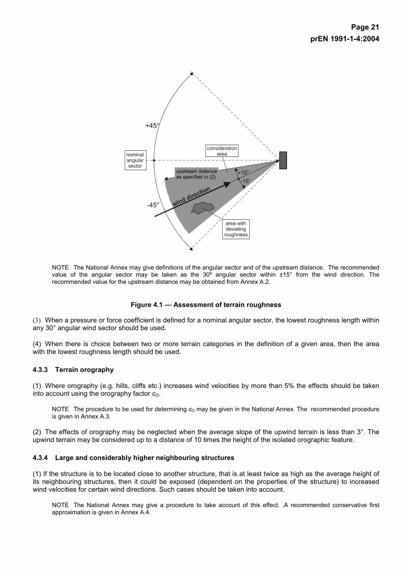
Page 21 prEN 1991-1-4:2004
NOTE The National Annex may give definitions of the angular sector and of the upstream distance. The recommended value of the angular sector may be taken as the 30º angular sector within ±15° from the wind direction. The recommended value for the upstream distance may be obtained from Annex A.2.
Figure 4.1 — Assessment of terrain roughness
(3) When a pressure or force coefficient is defined for a nominal angular sector, the lowest roughness length within any 30° angular wind sector should be used.
(4) When there is choice between two or more terrain categories in the definition of a given area, then the area with the lowest roughness length should be used.
4.3.3 Terrain orography
(1) Where orography (e.g. hills, cliffs etc.) increases wind velocities by more than 5% the effects should be taken into account using the orography factor cO.
NOTE The procedure to be used for determining cO may be given in the National Annex. The recommended procedure is given in Annex A.3.
(2) The effects of orography may be neglected when the average slope of the upwind terrain is less than 3°. The upwind terrain may be considered up to a distance of 10 times the height of the isolated orographic feature.
4.3.4 Large and considerably higher neighbouring structures
(1) If the structure is to be located close to another structure, that is at least twice as high as the average height of its neighbouring structures, then it could be exposed (dependent on the properties of the structure) to increased wind velocities for certain wind directions. Such cases should be taken into account.
NOTE The National Annex may give a procedure to take account of this effect. .A recommended conservative first approximation is given in Annex A.4.
Page 22 prEN 1991-1-4:2004
4.3.5 Closely spaced buildings and obstacles
(1) The effect of closely spaced buildings and other obstacles may be taken into account.
NOTE The National Annex may give a procedure. A recommended first approximation is given in Annex A.5. In rough terrain closely spaced buildings modify the mean wind flow near the ground, as if the ground level was raised to a height called displacement height hdis.
4.4 Wind turbulence
(1) The turbulence intensity Iv(z) at height z is defined as the standard deviation of the turbulence divided by the mean wind velocity.
NOTE 1 The turbulent component of wind velocity has a mean value of 0 and a standard deviation σv. The standard deviation of the turbulence σv may be determined using Expression (4.6).
Ibrv kvk ⋅⋅=σ (4.6)
For the terrain factor kr see Expression (4.5), for the basic wind velocity vb see Expression (4.1) and for turbulence factor kI see Note 2.
NOTE 2 The recommended rules for the determination of Iv(z) are given in Expression (4.7)
minminvv
maxmin0o
I
m
vv
for)()(
for)/ln()()(
)(
zzzIzI
zzzzzzc
kzv
zI
<=
≤≤⋅
==σ
(4.7)
where:
kI is the turbulence factor. The value of kI may be given in the National Annex. The recommended value is kI = 1,0.
co is the orography factor as described in 4.3.3
z0 is the roughness length, given in Table 4.1
4.5 Peak velocity pressure
(1) The peak velocity pressure qp(z) at height z, which includes mean and short-term velocity fluctuations, should be determined.
NOTE 1 The National Annex may give rules for the determination of qp(z). The recommended rule is given in Expression (4.8).
[ ] be2mvp )()(
21)(71)( qzczvzIzq ⋅=⋅⋅⋅⋅+= ρ (4.8)
where:
ρ is the air density, which depends on the altitude, temperature and barometric pressure to be expected in the region during wind storms
ce(z) is the exposure factor given in Expression (4.9)
b
pe
)()(
qzq
zc = (4.9)
qb is the basic velocity pressure given in Expression (4.10)
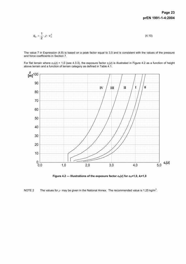
Page 23 prEN 1991-1-4:2004
2bb 2
1 vq ⋅⋅= ρ (4.10)
The value 7 in Expression (4.8) is based on a peak factor equal to 3,5 and is consistent with the values of the pressure and force coefficients in Section 7.
For flat terrain where cO(z) = 1,0 (see 4.3.3), the exposure factor ce(z) is illustrated in Figure 4.2 as a function of height above terrain and a function of terrain category as defined in Table 4.1.
Figure 4.2 — Illustrations of the exposure factor ce(z) for cO=1,0, kI=1,0
NOTE 2 The values for ρ may be given in the National Annex. The recommended value is 1,25 kg/m3.

Page 24 prEN 1991-1-4:2004
5 Wind actions
5.1 General
(1)P Wind actions on structures and structural elements shall be determined taking account of both external and internal wind pressures.
NOTE A summary of calculation procedures for the determination of wind actions is given in Table 5.1.
Table 5.1 —Calculation procedures for the determination of wind actions
Parameter Subject Reference
peak velocity pressure qp
basic wind velocity vb 4.2 (2)P
reference height ze Section 7
terrain category Table 4.1
characteristic peak velocity pressure qp 4.5 (1)
turbulence intensity Iv 4.4
mean wind velocity vm 4.3.1
orography coefficient co(z) 4.3.3
roughness coefficient cr(z) 4.3.2
Wind pressures, e.g. for cladding, fixings and structural parts
internal pressure coefficient cpi Section 7
external pressure coefficient cpe Section 7
external wind pressure: we=qp cpe 5.2 (1)
internal wind pressure: wi=qp cpi 5.2 (2)
Wind forces on structures, e.g. for overall wind effects
structural factor: cscd 6
wind force Fw calculated from force coefficients 5.3 (2)
wind force Fw calculated from pressure coefficients 5.3 (3)
5.2 Wind pressure on surfaces
(1) The wind pressure acting on the external surfaces, we , should be obtained from Expression (5.1).
peepe )( czqw ⋅= (5.1)
where:
qp(ze) is the peak velocity pressure
ze is the reference height for the external pressure given in Section 7
cpe is the pressure coefficient for the external pressure, see Section 7.
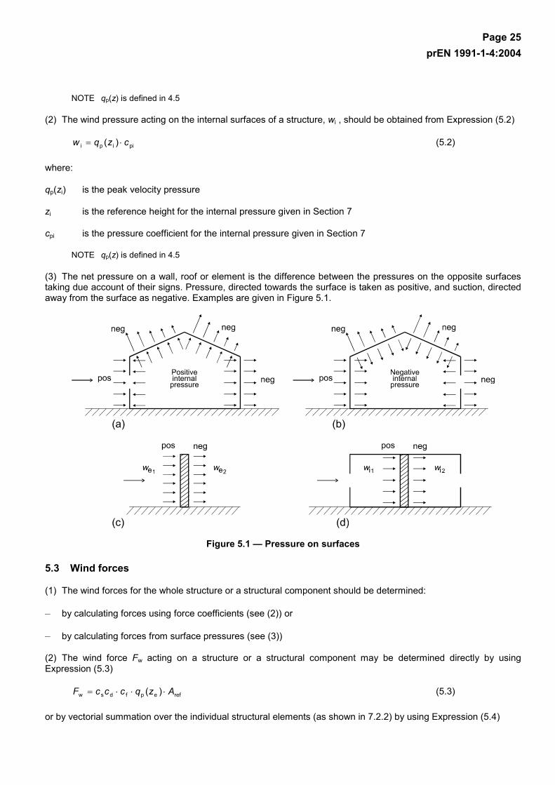
Page 25 prEN 1991-1-4:2004
NOTE qp(z) is defined in 4.5
(2) The wind pressure acting on the internal surfaces of a structure, wi , should be obtained from Expression (5.2)
piipi )( czqw ⋅= (5.2)
where:
qp(zi) is the peak velocity pressure
zi is the reference height for the internal pressure given in Section 7
cpi is the pressure coefficient for the internal pressure given in Section 7
NOTE qp(z) is defined in 4.5
(3) The net pressure on a wall, roof or element is the difference between the pressures on the opposite surfaces taking due account of their signs. Pressure, directed towards the surface is taken as positive, and suction, directed away from the surface as negative. Examples are given in Figure 5.1.
Figure 5.1 — Pressure on surfaces
5.3 Wind forces
(1) The wind forces for the whole structure or a structural component should be determined:
– by calculating forces using force coefficients (see (2)) or
– by calculating forces from surface pressures (see (3))
(2) The wind force Fw acting on a structure or a structural component may be determined directly by using Expression (5.3)
refepfdsw )( AzqcccF ⋅⋅⋅= (5.3)
or by vectorial summation over the individual structural elements (as shown in 7.2.2) by using Expression (5.4)

Page 26 prEN 1991-1-4:2004
∑ ⋅⋅⋅=elements
refepfdsw )( AzqcccF (5.4)
where:
cscd is the structural factor as defined in Section 6
cf is the force coefficient for the structure or structural element, given in Section 7 or Section 8
qp(ze) is the peak velocity pressure (defined in 4.5) at reference height ze (defined in Section 7 or Section 8)
Aref is the reference area of the structure or structural element, given in Section 7 or Section 8
NOTE Section 7 gives cf values for structures or structural elements such as prisms, cylinders, roofs, signboards, plates and lattice structures etc. These values include friction effects. Section 8 gives cf values for bridges.
(3) The wind force, Fw acting on a structure or a structural element may be determined by vectorial summation of the forces Fw,e, Fw,i and Ffr calculated from the external and internal pressures using Expressions (5.5) and (5.6) and the frictional forces resulting from the friction of the wind parallel to the external surfaces, calculated using Expression (5.7).
external forces:
∑ ⋅⋅=surfaces
refedsw,e AwccF (5.5)
internal forces:
∑ ⋅=surfaces
refiiw, AwF (5.6)
friction forces:
frepfrfr )( AzqcF ⋅⋅= (5.7)
where:
cscd is the structural factor as defined in Section 6
we is the external pressure on the individual surface at height ze, given in Expression (5.1)
wi is the internal pressure on the individual surface at height zi, given in Expression (5.2)
Aref is the reference area of the individual surface
cfr is the friction coefficient derived from 7.5
Afr is the area of external surface parallel to the wind, given in 7.5.
NOTE 1 For elements (e.g. walls, roofs), the wind force becomes equal to the difference between the external and internal resulting forces.
NOTE 2 Friction forces Ffr act in the direction of the wind components parallel to external surfaces.
(4) The effects of wind friction on the surface can be disregarded when the total area of all surfaces parallel with (or at a small angle to) the wind is equal to or less than 4 times the total area of all external surfaces perpendicular to the wind (windward and leeward).

Page 27 prEN 1991-1-4:2004
(5) In the summation of the wind forces acting on building structures, the lack of correlation of wind pressures between the windward and leeward sides may be taken into account.
NOTE The National Annex may determine whether this lack of correlation may be applied generally or be restricted to walls as applied in 7.2.2 (3). It is recommended to consider the lack of correlation only for walls (see 7.2.2 (3)).
Page 28 prEN 1991-1-4:2004
6 Structural factor cscd
6.1 General
(1) The structural factor cscd should take into account the effect on wind actions from the non-simultaneous occurrence of peak wind pressures on the surface together with the effect of the vibrations of the structure due to turbulence.
NOTE The structural factor cscd may be separated into a size factor cs and a dynamic factor cd, based on 6.3. Information on whether the structural factor cscd should be separated or not may be given in the National Annex.
6.2 Determination of cscd
(1) cscd should be determined as follows:
a) For buildings with a height less than 15 m the value of cscd may be taken as 1.
b) For facade and roof elements having a natural frequency greater than 5 Hz, the value of cscd may be taken as 1.
c) For framed buildings which have structural walls and which are less than 100 m high and whose height is less than 4 times the in-wind depth, the value of cscd may be taken as 1.
d) For chimneys with circular cross-sections whose height is less than 60 m and 6,5 times the diameter, the value of cscd may be taken as 1.
e) Alternatively, for cases a), b), c) and d) above, values of cscd may be derived from 6.3.1.
f) For civil engineering works (other than bridges, which are considered in Section 8), andchimneys and buildings outside the limitations given in c) and d) above, cscd should be derived either from 6.3 or taken from Annex D.
NOTE 1 Natural frequencies of facade and roof elements may be calculated using Annex F (glazing spans smaller than 3 m usually lead to natural frequencies greater than 5 Hz)
NOTE 2 The figures in Annex D give values of cscd for various types of structures. The figures give envelopes of safe values calculated from models complying with the requirements in 6.3.1.
6.3 Detailed procedure
6.3.1 Structural factor cscd
(1) The detailed procedure for calculating the structural factor cscd is given in Expression (6.1). This procedure can only be used if the conditions given in 6.3.1 (2) apply.
)(71
)(21
ev
22evp
ds zIRBzIk
cc⋅+
+⋅⋅⋅+= (6.1)
where:
ze is the reference height, see Figure 6.1. For structures where Figure 6.1 does not apply ze may be equal to h, the height of the structure.
kp is the peak factor defined as the ratio of the maximum value of the fluctuating part of the response to its standard deviation
Iv is the turbulence intensity defined in 4.4
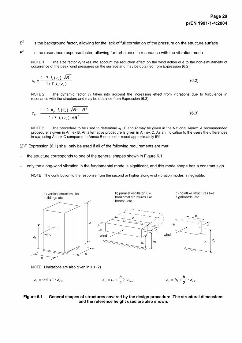
Page 29 prEN 1991-1-4:2004
B2 is the background factor, allowing for the lack of full correlation of the pressure on the structure surface
R2 is the resonance response factor, allowing for turbulence in resonance with the vibration mode
NOTE 1 The size factor cs takes into account the reduction effect on the wind action due to the non-simultaneity of occurrence of the peak wind pressures on the surface and may be obtained from Expression (6.2):
)(71
)(71
ev
2ev
s zIBzI
c⋅+
⋅⋅+= (6.2)
NOTE 2 The dynamic factor cd takes into account the increasing effect from vibrations due to turbulence in resonance with the structure and may be obtained from Expression (6.3):
2
ev
22evp
d)(71
)(21
BzI
RBzIkc
⋅⋅+
+⋅⋅⋅+= (6.3)
NOTE 3 The procedure to be used to determine kp, B and R may be given in the National Annex. A recommended procedure is given in Annex B. An alternative procedure is given in Annex C. As an indication to the users the differences in cscd using Annex C compared to Annex B does not exceed approximately 5%.
(2)P Expression (6.1) shall only be used if all of the following requirements are met:
– the structure corresponds to one of the general shapes shown in Figure 6.1,
– only the along-wind vibration in the fundamental mode is significant, and this mode shape has a constant sign.
NOTE The contribution to the response from the second or higher alongwind vibration modes is negligible.
NOTE Limitations are also given in 1.1 (2)
mine 6,0 zhz ≥⋅= min1e 2zhhz ≥+= min1e 2
zhhz ≥+=
Figure 6.1 — General shapes of structures covered by the design procedure. The structural dimensions and the reference height used are also shown.

Page 30 prEN 1991-1-4:2004
6.3.2 Serviceability assessments
(1) For serviceability assessments, the maximum along-wind displacement and the standard deviation of the characteristic along-wind acceleration of the structure at height z should be used. For the maximum along-wind displacement the equivalent static wind force defined in 5.2 should be used.
NOTE The National Annex may give a method for determining the along-wind displacement and the standard deviation of the along-wind acceleration. The recommended method is given in Annex B. An alternative method is given in Annex C.
6.3.3 Wake buffeting
(1) For slender buildings (h/d > 4) and chimneys (h/d > 6,5) in tandem or grouped arrangement, the effect of increased turbulence in the wake of nearby structures (wake buffeting) should be taken into account.
(2) Wake buffeting effects may be assumed to be negligible if at least one of the following conditions applies:
– The distance between two buildings or chimneys is larger than 25 times the cross wind dimension of the upstream building or chimney.
– The natural frequency of the downstream building or chimney is higher than 1 Hz.
NOTE If 6.3.3 (2) is not fulfilled wind tunnel tests or specialist advice is recommended.

Page 31 prEN 1991-1-4:2004
7 Pressure and force coefficients
7.1 General
(1) This section should be used to determine the appropriate aerodynamic coefficients for structures. Depending on the structure the appropriate aerodynamic coefficient will be:
– Internal and external pressure coefficients, see 7.1.1 (1),
– Net pressure coefficients, see 7.1.1 (2),
– Friction coefficients, see 7.1.1 (3),
– Force coefficients, see 7.1.1 (4).
7.1.1 Choice of aerodynamic coefficient
(1) Pressure coefficients should be determined for:
– Buildings, using 7.2 for both internal and external pressures, and for
– Circular cylinders, using 7.2.9 for the internal pressures and 7.9.1 for the external pressures
NOTE 1 External pressure coefficients give the effect of the wind on the external surfaces of buildings; internal pressure coefficients give the effect of the wind on the internal surfaces of buildings.
NOTE 2 The external pressure coefficients are divided into overall coefficients and local coefficients. Local coefficients give the pressure coefficients for loaded areas of 1 m2 . They may be used for the design of small elements and fixings. Overall coefficients give the pressure coefficients for loaded areas of 10 m2. They may be used for loaded areas larger than 10 m2.
(2) Net pressure coefficients should be determined for:
– Canopy roofs, using 7.3
– Free-standing walls, parapets and fences using 7.4
NOTE Net pressure coefficients give the resulting effect of the wind on a structure, structural element or component per unit area.
(3) Friction coefficients should be determined for walls and surfaces defined in 5.2 (3), using 7.5.
(4) Force coefficients should be determined for:
– Signboards, using 7.4.3,
– Structural elements with rectangular cross section, using 7.6,
– Structural elements with sharp edged section, using 7.7,
– Structural elements with regular polygonal section, using 7.8,
– Circular cylinders, using 7.9.2 and 7.9.3,
– Spheres, using 7.10,
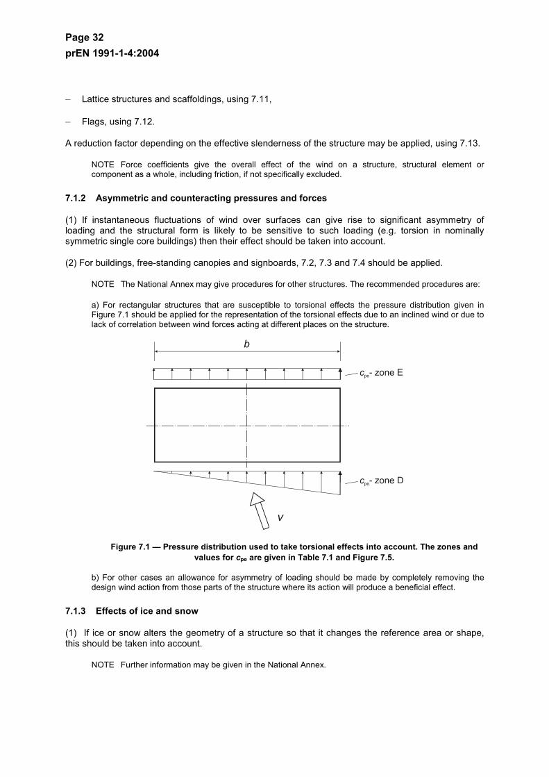
Page 32 prEN 1991-1-4:2004
– Lattice structures and scaffoldings, using 7.11,
– Flags, using 7.12.
A reduction factor depending on the effective slenderness of the structure may be applied, using 7.13.
NOTE Force coefficients give the overall effect of the wind on a structure, structural element or component as a whole, including friction, if not specifically excluded.
7.1.2 Asymmetric and counteracting pressures and forces
(1) If instantaneous fluctuations of wind over surfaces can give rise to significant asymmetry of loading and the structural form is likely to be sensitive to such loading (e.g. torsion in nominally symmetric single core buildings) then their effect should be taken into account.
(2) For buildings, free-standing canopies and signboards, 7.2, 7.3 and 7.4 should be applied.
NOTE The National Annex may give procedures for other structures. The recommended procedures are:
a) For rectangular structures that are susceptible to torsional effects the pressure distribution given in Figure 7.1 should be applied for the representation of the torsional effects due to an inclined wind or due to lack of correlation between wind forces acting at different places on the structure.
Figure 7.1 — Pressure distribution used to take torsional effects into account. The zones and values for cpe are given in Table 7.1 and Figure 7.5.
b) For other cases an allowance for asymmetry of loading should be made by completely removing the design wind action from those parts of the structure where its action will produce a beneficial effect.
7.1.3 Effects of ice and snow
(1) If ice or snow alters the geometry of a structure so that it changes the reference area or shape, this should be taken into account.
NOTE Further information may be given in the National Annex.
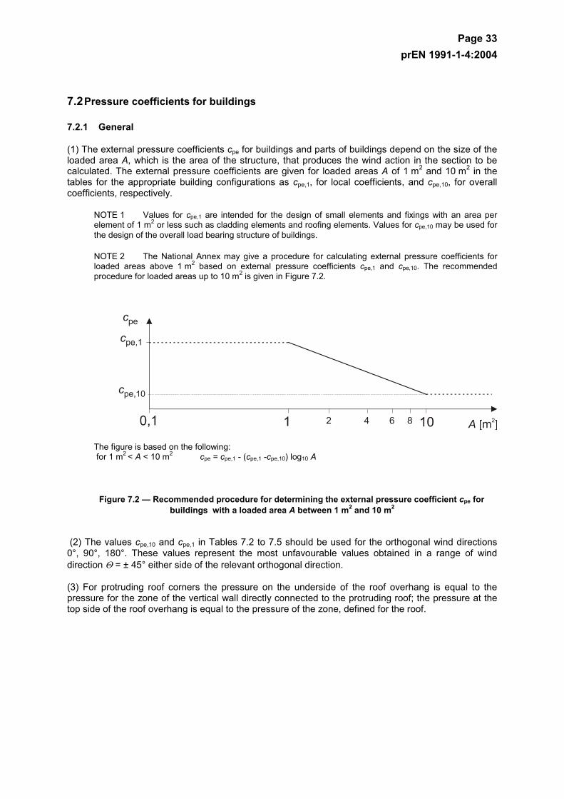
Page 33 prEN 1991-1-4:2004
7.2 Pressure coefficients for buildings
7.2.1 General
(1) The external pressure coefficients cpe for buildings and parts of buildings depend on the size of the loaded area A, which is the area of the structure, that produces the wind action in the section to be calculated. The external pressure coefficients are given for loaded areas A of 1 m2 and 10 m2 in the tables for the appropriate building configurations as cpe,1, for local coefficients, and cpe,10, for overall coefficients, respectively.
NOTE 1 Values for cpe,1 are intended for the design of small elements and fixings with an area per element of 1 m2 or less such as cladding elements and roofing elements. Values for cpe,10 may be used for the design of the overall load bearing structure of buildings.
NOTE 2 The National Annex may give a procedure for calculating external pressure coefficients for loaded areas above 1 m2 based on external pressure coefficients cpe,1 and cpe,10. The recommended procedure for loaded areas up to 10 m2 is given in Figure 7.2.
The figure is based on the following: for 1 m2 < A < 10 m2 cpe = cpe,1 - (cpe,1 -cpe,10) log10 A
Figure 7.2 — Recommended procedure for determining the external pressure coefficient cpe for buildings with a loaded area A between 1 m2 and 10 m2
(2) The values cpe,10 and cpe,1 in Tables 7.2 to 7.5 should be used for the orthogonal wind directions 0°, 90°, 180°. These values represent the most unfavourable values obtained in a range of wind direction Θ = ± 45° either side of the relevant orthogonal direction.
(3) For protruding roof corners the pressure on the underside of the roof overhang is equal to the pressure for the zone of the vertical wall directly connected to the protruding roof; the pressure at the top side of the roof overhang is equal to the pressure of the zone, defined for the roof.
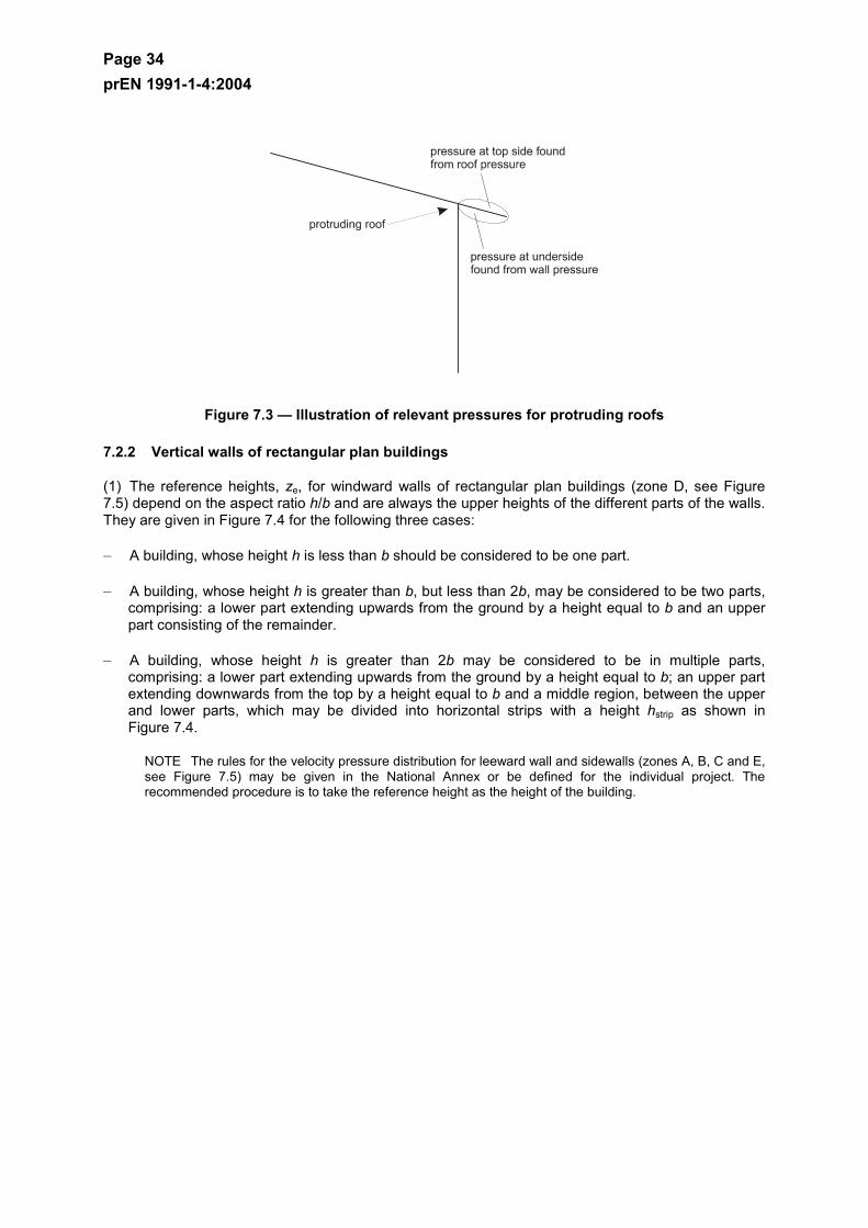
Page 34 prEN 1991-1-4:2004
Figure 7.3 — Illustration of relevant pressures for protruding roofs
7.2.2 Vertical walls of rectangular plan buildings
(1) The reference heights, ze, for windward walls of rectangular plan buildings (zone D, see Figure 7.5) depend on the aspect ratio h/b and are always the upper heights of the different parts of the walls. They are given in Figure 7.4 for the following three cases:
– A building, whose height h is less than b should be considered to be one part.
– A building, whose height h is greater than b, but less than 2b, may be considered to be two parts, comprising: a lower part extending upwards from the ground by a height equal to b and an upper part consisting of the remainder.
– A building, whose height h is greater than 2b may be considered to be in multiple parts, comprising: a lower part extending upwards from the ground by a height equal to b; an upper part extending downwards from the top by a height equal to b and a middle region, between the upper and lower parts, which may be divided into horizontal strips with a height hstrip as shown in Figure 7.4.
NOTE The rules for the velocity pressure distribution for leeward wall and sidewalls (zones A, B, C and E, see Figure 7.5) may be given in the National Annex or be defined for the individual project. The recommended procedure is to take the reference height as the height of the building.
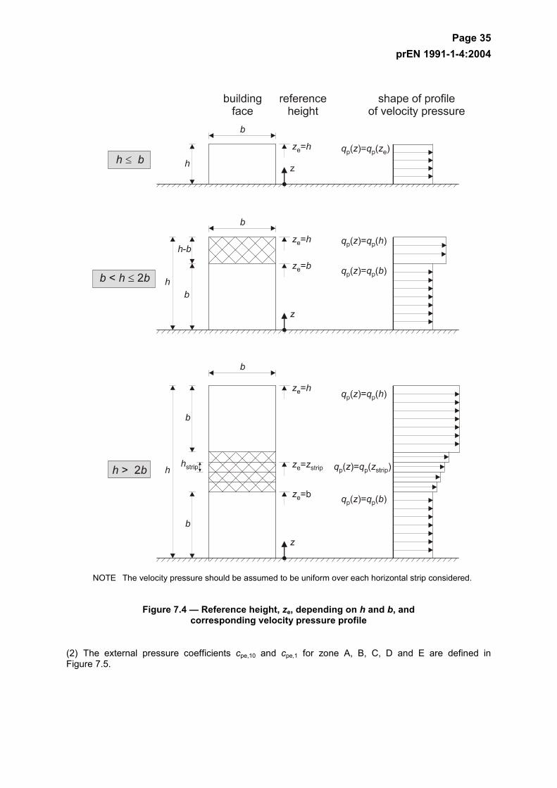
Page 35 prEN 1991-1-4:2004
NOTE The velocity pressure should be assumed to be uniform over each horizontal strip considered.
Figure 7.4 — Reference height, ze, depending on h and b, and corresponding velocity pressure profile
(2) The external pressure coefficients cpe,10 and cpe,1 for zone A, B, C, D and E are defined in Figure 7.5.
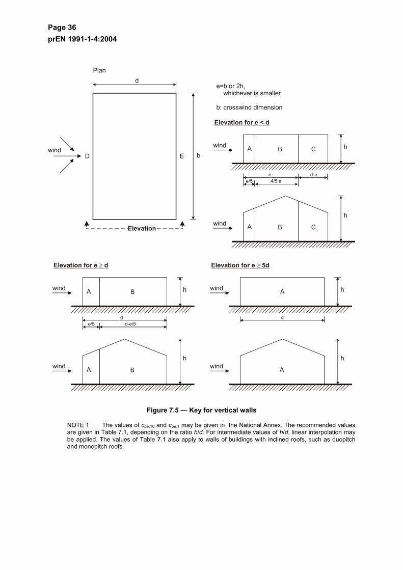
Page 36 prEN 1991-1-4:2004
Figure 7.5 — Key for vertical walls
NOTE 1 The values of cpe,10 and cpe,1 may be given in the National Annex. The recommended values are given in Table 7.1, depending on the ratio h/d. For intermediate values of h/d, linear interpolation may be applied. The values of Table 7.1 also apply to walls of buildings with inclined roofs, such as duopitch and monopitch roofs.
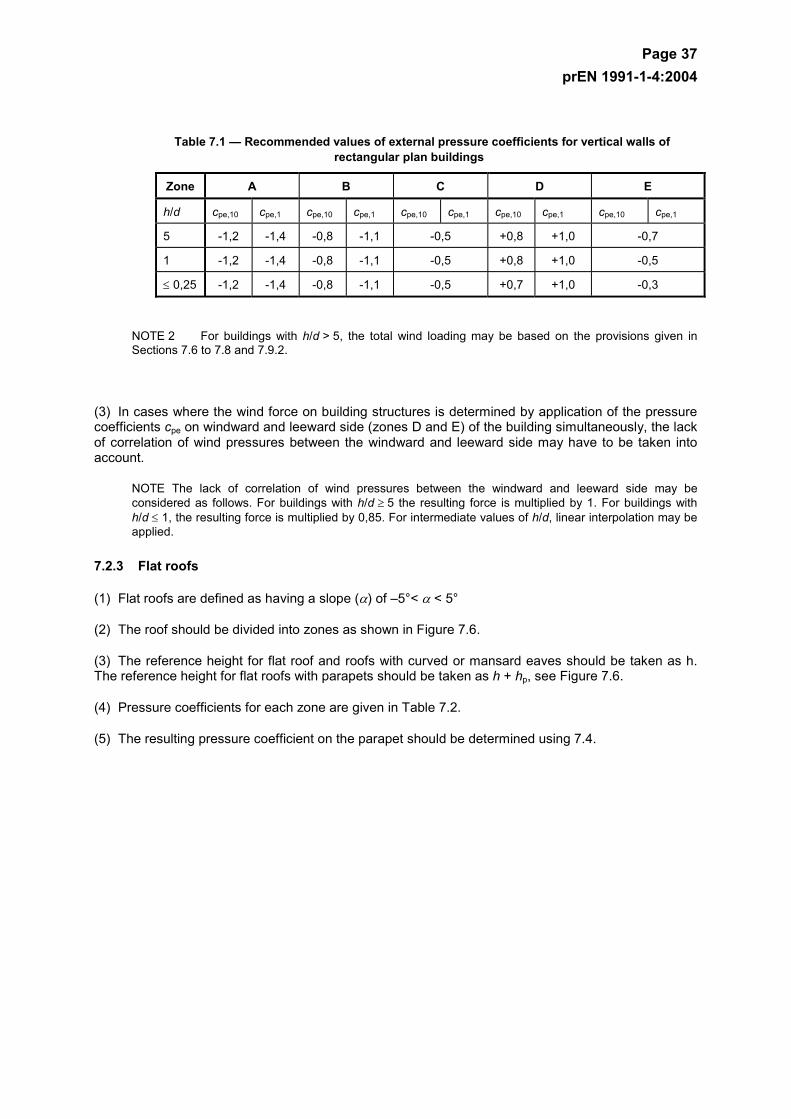
Page 37 prEN 1991-1-4:2004
Table 7.1 — Recommended values of external pressure coefficients for vertical walls of rectangular plan buildings
Zone A B C D E
h/d cpe,10 cpe,1 cpe,10 cpe,1 cpe,10 cpe,1 cpe,10 cpe,1 cpe,10 cpe,1
5 -1,2 -1,4 -0,8 -1,1 -0,5 +0,8 +1,0 -0,7
1 -1,2 -1,4 -0,8 -1,1 -0,5 +0,8 +1,0 -0,5
≤ 0,25 -1,2 -1,4 -0,8 -1,1 -0,5 +0,7 +1,0 -0,3
NOTE 2 For buildings with h/d > 5, the total wind loading may be based on the provisions given in Sections 7.6 to 7.8 and 7.9.2.
(3) In cases where the wind force on building structures is determined by application of the pressure coefficients cpe on windward and leeward side (zones D and E) of the building simultaneously, the lack of correlation of wind pressures between the windward and leeward side may have to be taken into account.
NOTE The lack of correlation of wind pressures between the windward and leeward side may be considered as follows. For buildings with h/d ≥ 5 the resulting force is multiplied by 1. For buildings with h/d ≤ 1, the resulting force is multiplied by 0,85. For intermediate values of h/d, linear interpolation may be applied.
7.2.3 Flat roofs
(1) Flat roofs are defined as having a slope (α) of –5°< α < 5°
(2) The roof should be divided into zones as shown in Figure 7.6.
(3) The reference height for flat roof and roofs with curved or mansard eaves should be taken as h. The reference height for flat roofs with parapets should be taken as h + hp, see Figure 7.6.
(4) Pressure coefficients for each zone are given in Table 7.2.
(5) The resulting pressure coefficient on the parapet should be determined using 7.4.
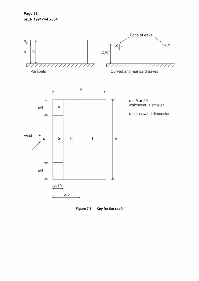
Page 38 prEN 1991-1-4:2004
Figure 7.6 — Key for flat roofs
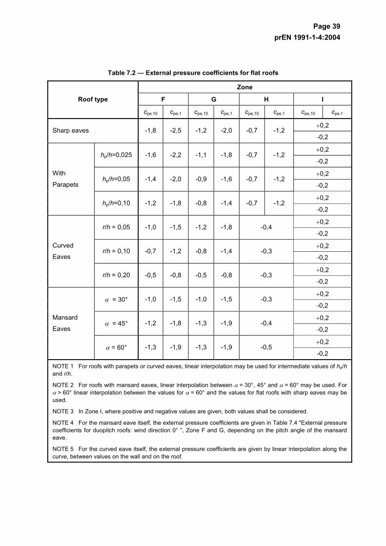
Page 39 prEN 1991-1-4:2004
Table 7.2 — External pressure coefficients for flat roofs
Zone
F G H I Roof type
cpe,10 cpe,1 cpe,10 cpe,1 cpe,10 cpe,1 cpe,10 cpe,1
+0,2 Sharp eaves -1,8 -2,5 -1,2 -2,0 -0,7 -1,2
-0,2
+0,2 hp/h=0,025 -1,6 -2,2 -1,1 -1,8 -0,7 -1,2
-0,2
+0,2 hp/h=0,05 -1,4 -2,0 -0,9 -1,6 -0,7 -1,2
-0,2
+0,2
With
Parapets
hp/h=0,10 -1,2 -1,8 -0,8 -1,4 -0,7 -1,2 -0,2
+0,2 r/h = 0,05 -1,0 -1,5 -1,2 -1,8 -0,4
-0,2
+0,2 r/h = 0,10 -0,7 -1,2 -0,8 -1,4 -0,3
-0,2
+0,2
Curved
Eaves
r/h = 0,20 -0,5 -0,8 -0,5 -0,8 -0,3 -0,2
+0,2 α = 30° -1,0 -1,5 -1,0 -1,5 -0,3
-0,2
+0,2 α = 45° -1,2 -1,8 -1,3 -1,9 -0,4
-0,2
+0,2
Mansard
Eaves
α = 60° -1,3 -1,9 -1,3 -1,9 -0,5 -0,2
NOTE 1 For roofs with parapets or curved eaves, linear interpolation may be used for intermediate values of hp/h and r/h.
NOTE 2 For roofs with mansard eaves, linear interpolation between α = 30°, 45° and α = 60° may be used. For α > 60° linear interpolation between the values for α = 60° and the values for flat roofs with sharp eaves may be used.
NOTE 3 In Zone I, where positive and negative values are given, both values shall be considered.
NOTE 4 For the mansard eave itself, the external pressure coefficients are given in Table 7.4 "External pressure coefficients for duopitch roofs: wind direction 0° ”, Zone F and G, depending on the pitch angle of the mansard eave.
NOTE 5 For the curved eave itself, the external pressure coefficients are given by linear interpolation along the curve, between values on the wall and on the roof.

Page 40 prEN 1991-1-4:2004
7.2.4 Monopitch roofs
(1) The roof, including protruding parts, should be divided into zones as shown in Figure 7.7.
(2) The reference height ze should be taken equal to h.
(3) The pressure coefficients for each zone that should be used are given in Table 7.3.
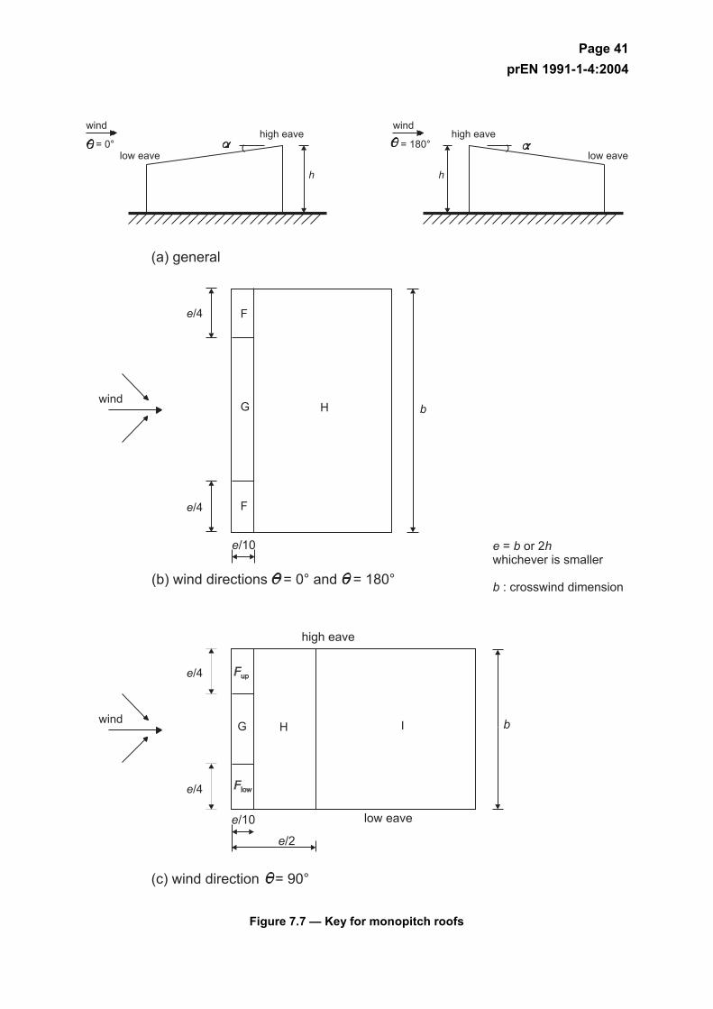
Page 41 prEN 1991-1-4:2004
Figure 7.7 — Key for monopitch roofs
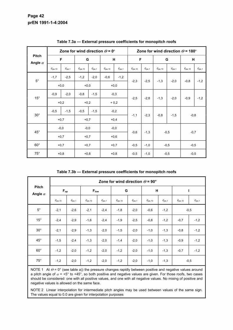
Page 42 prEN 1991-1-4:2004
Table 7.3a — External pressure coefficients for monopitch roofs
Zone for wind direction Θ = 0° Zone for wind direction Θ = 180°
F G H F G H Pitch
Angle α cpe,10 cpe,1 cpe,10 cpe,1 cpe,10 cpe,1 cpe,10 cpe,1 cpe,10 cpe,1 cpe,10 cpe,1
-1,7 -2,5 -1,2 -2,0 -0,6 -1,2 5°
+0,0 +0,0 +0,0 -2,3 -2,5 -1,3 -2,0 -0,8 -1,2
-0,9 -2,0 -0,8 -1,5 -0,3 15°
+0,2 +0,2 + 0,2 -2,5 -2,8 -1,3 -2,0 -0,9 -1,2
-0,5 -1,5 -0,5 -1,5 -0,2 30°
+0,7 +0,7 +0,4 -1,1 -2,3 -0,8 -1,5 -0,8
-0,0 -0,0 -0,0 45°
+0,7 +0,7 +0,6 -0,6 -1,3 -0,5 -0,7
60° +0,7 +0,7 +0,7 -0,5 -1,0 -0,5 -0,5
75° +0,8 +0,8 +0,8 -0,5 -1,0 -0,5 -0,5
Table 7.3b — External pressure coefficients for monopitch roofs
Zone for wind direction Θ = 90°
Fup Flow G H I Pitch
Angle α
cpe,10 cpe,1 cpe,10 cpe,1 cpe,10 cpe,1 cpe,10 cpe,1 cpe,10 cpe,1
5° -2,1 -2,6 -2,1 -2,4 -1,8 -2,0 -0,6 -1,2 -0,5
15° -2,4 -2,9 -1,6 -2,4 -1,9 -2,5 -0,8 -1,2 -0,7 -1,2
30° -2,1 -2,9 -1,3 -2,0 -1,5 -2,0 -1,0 -1,3 -0,8 -1,2
45° -1,5 -2,4 -1,3 -2,0 -1,4 -2,0 -1,0 -1,3 -0,9 -1,2
60° -1,2 -2,0 -1,2 -2,0 -1,2 -2,0 -1,0 -1,3 -0,7 -1,2
75° -1,2 -2,0 -1,2 -2,0 -1,2 -2,0 -1,0 -1,3 -0,5
NOTE 1 At Θ = 0° (see table a)) the pressure changes rapidly between positive and negative values around a pitch angle of α = +5° to +45°, so both positive and negative values are given. For those roofs, two cases should be considered: one with all positive values, and one with all negative values. No mixing of positive and negative values is allowed on the same face.
NOTE 2 Linear interpolation for intermediate pitch angles may be used between values of the same sign. The values equal to 0.0 are given for interpolation purposes

Page 43 prEN 1991-1-4:2004
7.2.5 Duopitch roofs
(1) The roof, including protruding parts, should be divided in zones as shown in Figure 7.8.
(2) The reference height ze should be taken as h.
(3) The pressure coefficients for each zone that should be used are given in Table 7.4.
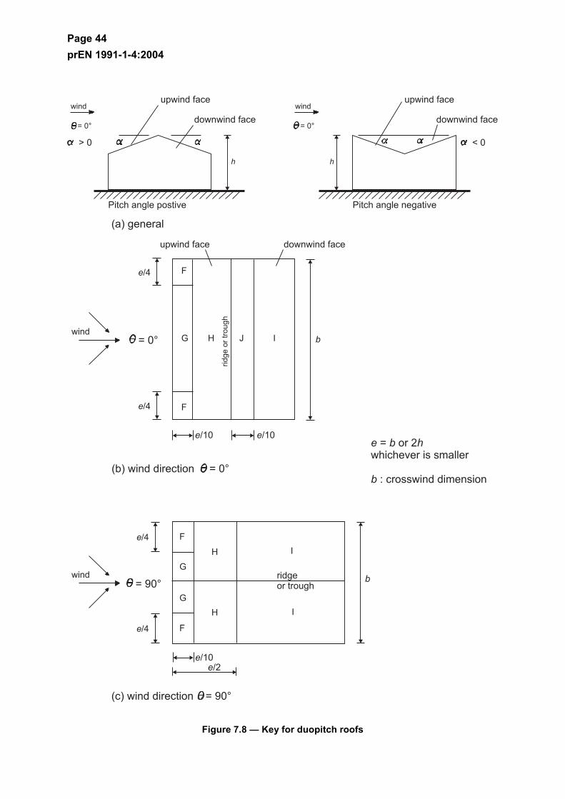
Page 44 prEN 1991-1-4:2004
Figure 7.8 — Key for duopitch roofs
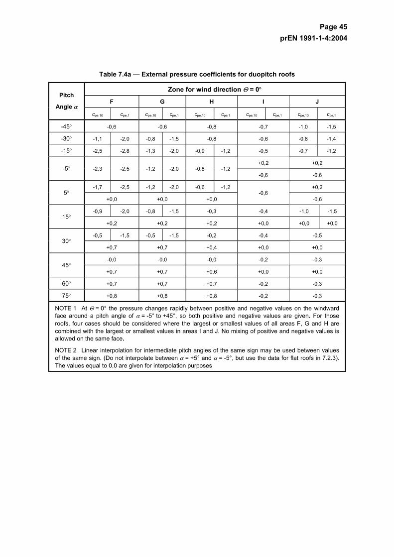
Page 45 prEN 1991-1-4:2004
Table 7.4a — External pressure coefficients for duopitch roofs
Zone for wind direction Θ = 0°
F G H I J Pitch
Angle α cpe,10 cpe,1 cpe,10 cpe,1 cpe,10 cpe,1 cpe,10 cpe,1 cpe,10 cpe,1
-45° -0,6 -0,6 -0,8 -0,7 -1,0 -1,5
-30° -1,1 -2,0 -0,8 -1,5 -0,8 -0,6 -0,8 -1,4
-15° -2,5 -2,8 -1,3 -2,0 -0,9 -1,2 -0,5 -0,7 -1,2
+0,2 +0,2 -5° -2,3 -2,5 -1,2 -2,0 -0,8 -1,2
-0,6 -0,6
-1,7 -2,5 -1,2 -2,0 -0,6 -1,2 +0,2 5°
+0,0 +0,0 +0,0 -0,6
-0,6
-0,9 -2,0 -0,8 -1,5 -0,3 -0,4 -1,0 -1,5 15°
+0,2 +0,2 +0,2 +0,0 +0,0 +0,0
-0,5 -1,5 -0,5 -1,5 -0,2 -0,4 -0,5 30°
+0,7 +0,7 +0,4 +0,0 +0,0
-0,0 -0,0 -0,0 -0,2 -0,3 45°
+0,7 +0,7 +0,6 +0,0 +0,0
60° +0,7 +0,7 +0,7 -0,2 -0,3
75° +0,8 +0,8 +0,8 -0,2 -0,3
NOTE 1 At Θ = 0° the pressure changes rapidly between positive and negative values on the windward face around a pitch angle of α = -5° to +45°, so both positive and negative values are given. For those roofs, four cases should be considered where the largest or smallest values of all areas F, G and H are combined with the largest or smallest values in areas I and J. No mixing of positive and negative values is allowed on the same face.
NOTE 2 Linear interpolation for intermediate pitch angles of the same sign may be used between values of the same sign. (Do not interpolate between α = +5° and α = -5°, but use the data for flat roofs in 7.2.3). The values equal to 0,0 are given for interpolation purposes
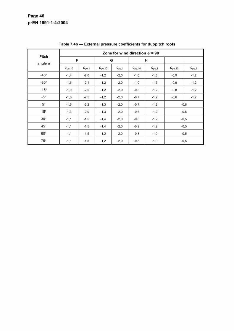
Page 46 prEN 1991-1-4:2004
Table 7.4b — External pressure coefficients for duopitch roofs
Zone for wind direction Θ = 90°
F G H I Pitch
angle α cpe,10 cpe,1 cpe,10 cpe,1 cpe,10 cpe,1 cpe,10 cpe,1
-45° -1,4 -2,0 -1,2 -2,0 -1,0 -1,3 -0,9 -1,2
-30° -1,5 -2,1 -1,2 -2,0 -1,0 -1,3 -0,9 -1,2
-15° -1,9 -2,5 -1,2 -2,0 -0,8 -1,2 -0,8 -1,2
-5° -1,8 -2,5 -1,2 -2,0 -0,7 -1,2 -0,6 -1,2
5° -1,6 -2,2 -1,3 -2,0 -0,7 -1,2 -0,6
15° -1,3 -2,0 -1,3 -2,0 -0,6 -1,2 -0,5
30° -1,1 -1,5 -1,4 -2,0 -0,8 -1,2 -0,5
45° -1,1 -1,5 -1,4 -2,0 -0,9 -1,2 -0,5
60° -1,1 -1,5 -1,2 -2,0 -0,8 -1,0 -0,5
75° -1,1 -1,5 -1,2 -2,0 -0,8 -1,0 -0,5
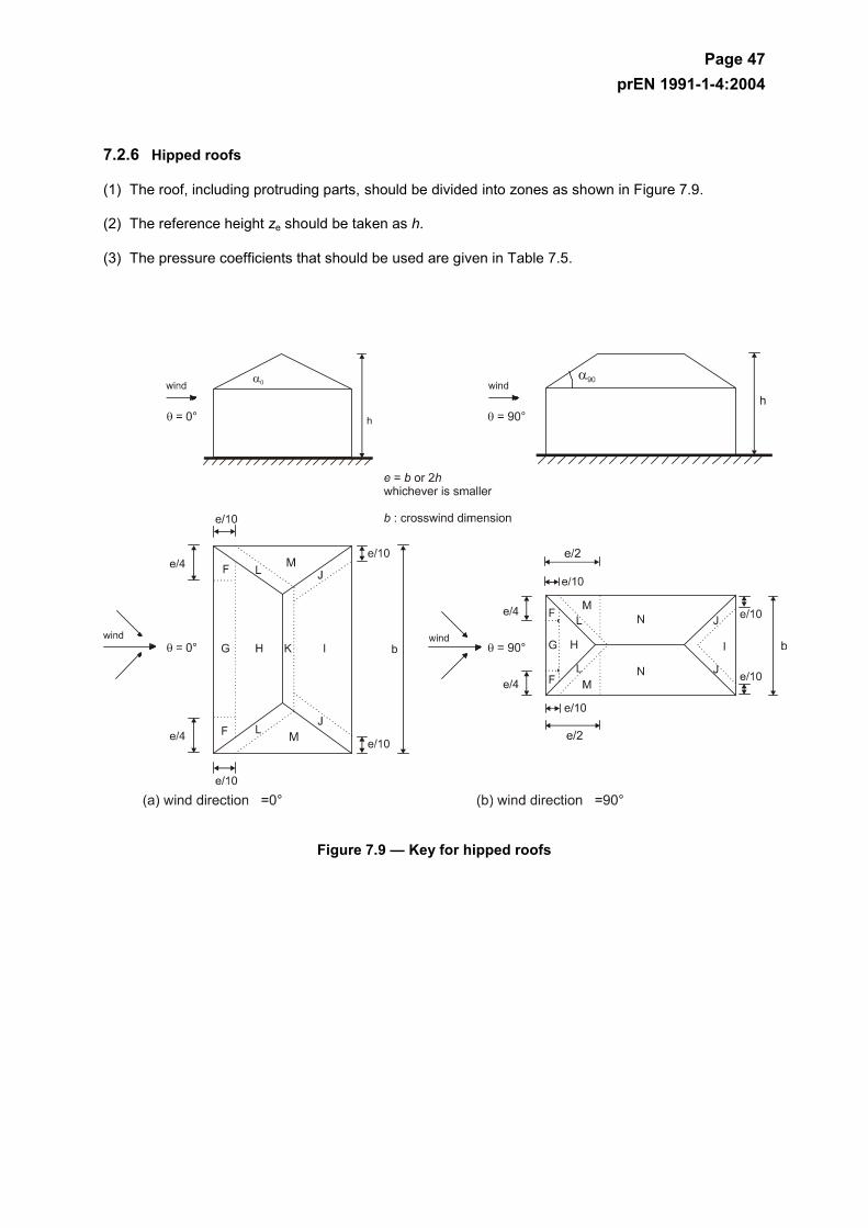
Page 47 prEN 1991-1-4:2004
7.2.6 Hipped roofs
(1) The roof, including protruding parts, should be divided into zones as shown in Figure 7.9.
(2) The reference height ze should be taken as h.
(3) The pressure coefficients that should be used are given in Table 7.5.
Figure 7.9 — Key for hipped roofs
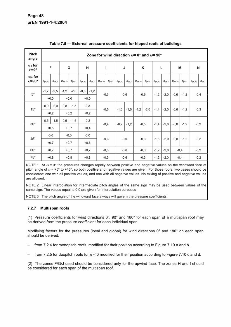
Page 48 prEN 1991-1-4:2004
Table 7.5 — External pressure coefficients for hipped roofs of buildings
Zone for wind direction Θ= 0° and Θ= 90°
F G H I J K L M N
Pitch angle
α0 for Θ=0°
α90 for Θ=90° cpe,10 cpe,1 cpe,10 cpe,1 cpe,10 cpe,1 cpe,10 cpe,1 cpe,10 cpe,1 cpe,10 cpe,1 cpe,10 cpe,1 cpe,10 cpe,1 cpe,10 cpe,1
-1,7 -2,5 -1,2 -2,0 -0,6 -1,2 5°
+0,0 +0,0 +0,0 -0,3 -0,6 -0,6 -1,2 -2,0 -0,6 -1,2 -0,4
-0,9 -2,0 -0,8 -1,5 -0,3 15°
+0,2 +0,2 +0,2 -0,5 -1,0 -1,5 -1,2 -2,0 -1,4 -2,0 -0,6 -1,2 -0,3
-0,5 -1,5 -0,5 -1,5 -0,2 30°
+0,5 +0,7 +0,4 -0,4 -0,7 -1,2 -0,5 -1,4 -2,0 -0,8 -1,2 -0,2
-0,0 -0,0 -0,0 45°
+0,7 +0,7 +0,6 -0,3 -0,6 -0,3 -1,3 -2,0 -0,8 -1,2 -0,2
60° +0,7 +0,7 +0,7 -0,3 -0,6 -0,3 -1,2 -2,0 -0,4 -0,2
75° +0,8 +0,8 +0,8 -0,3 -0,6 -0,3 -1,2 -2,0 -0,4 -0,2
NOTE 1 At Θ = 0° the pressures changes rapidly between positive and negative values on the windward face at pitch angle of α = +5° to +45°, so both positive and negative values are given. For those roofs, two cases should be considered: one with all positive values, and one with all negative values. No mixing of positive and negative values are allowed.
NOTE 2 Linear interpolation for intermediate pitch angles of the same sign may be used between values of the same sign. The values equal to 0,0 are given for interpolation purposes
NOTE 3 The pitch angle of the windward face always will govern the pressure coefficients.
7.2.7 Multispan roofs
(1) Pressure coefficients for wind directions 0°, 90° and 180° for each span of a multispan roof may be derived from the pressure coefficient for each individual span.
Modifying factors for the pressures (local and global) for wind directions 0° and 180° on each span should be derived:
– from 7.2.4 for monopitch roofs, modified for their position according to Figure 7.10 a and b.
– from 7.2.5 for duopitch roofs for α < 0 modified for their position according to Figure 7.10 c and d.
(2) The zones F/G/J used should be considered only for the upwind face. The zones H and I should be considered for each span of the multispan roof.
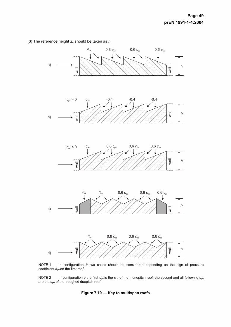
Page 49 prEN 1991-1-4:2004
(3) The reference height ze should be taken as h.
NOTE 1 In configuration b two cases should be considered depending on the sign of pressure coefficient cpe on the first roof.
NOTE 2 In configuration c the first cpe is the cpe of the monopitch roof, the second and all following cpe are the cpe of the troughed duopitch roof.
Figure 7.10 — Key to multispan roofs
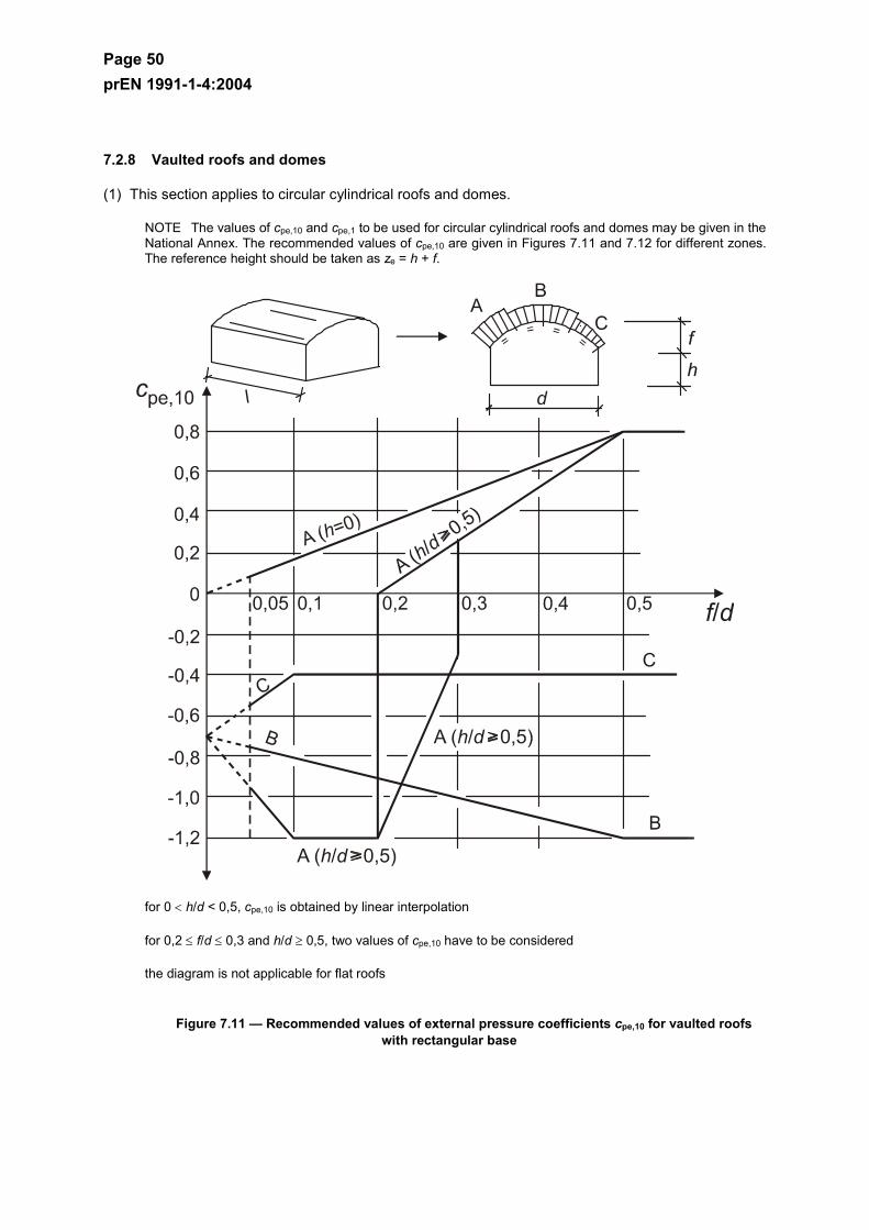
Page 50 prEN 1991-1-4:2004
7.2.8 Vaulted roofs and domes
(1) This section applies to circular cylindrical roofs and domes.
NOTE The values of cpe,10 and cpe,1 to be used for circular cylindrical roofs and domes may be given in the National Annex. The recommended values of cpe,10 are given in Figures 7.11 and 7.12 for different zones. The reference height should be taken as ze = h + f.
for 0 < h/d < 0,5, cpe,10 is obtained by linear interpolation
for 0,2 ≤ f/d ≤ 0,3 and h/d ≥ 0,5, two values of cpe,10 have to be considered
the diagram is not applicable for flat roofs
Figure 7.11 — Recommended values of external pressure coefficients cpe,10 for vaulted roofs with rectangular base
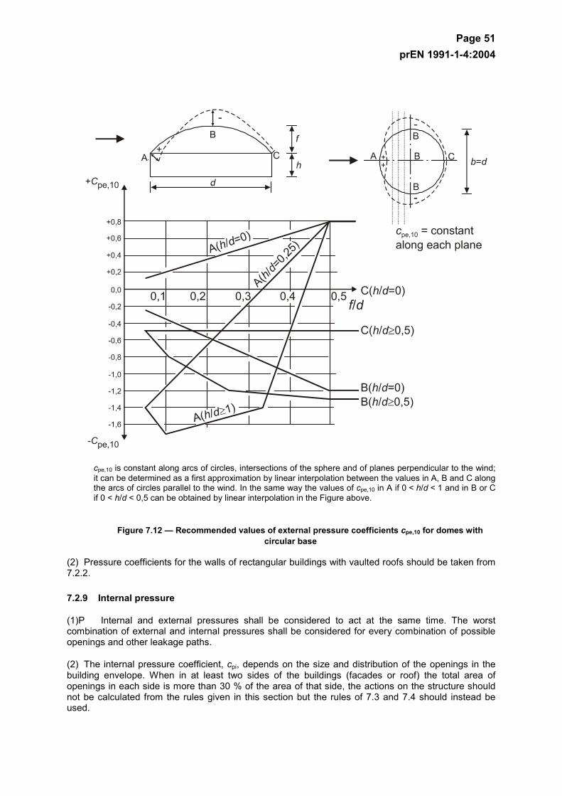
Page 51 prEN 1991-1-4:2004
cpe,10 is constant along arcs of circles, intersections of the sphere and of planes perpendicular to the wind; it can be determined as a first approximation by linear interpolation between the values in A, B and C along the arcs of circles parallel to the wind. In the same way the values of cpe,10 in A if 0 < h/d < 1 and in B or C if 0 < h/d < 0,5 can be obtained by linear interpolation in the Figure above.
Figure 7.12 — Recommended values of external pressure coefficients cpe,10 for domes with circular base
(2) Pressure coefficients for the walls of rectangular buildings with vaulted roofs should be taken from 7.2.2.
7.2.9 Internal pressure
(1)P Internal and external pressures shall be considered to act at the same time. The worst combination of external and internal pressures shall be considered for every combination of possible openings and other leakage paths.
(2) The internal pressure coefficient, cpi, depends on the size and distribution of the openings in the building envelope. When in at least two sides of the buildings (facades or roof) the total area of openings in each side is more than 30 % of the area of that side, the actions on the structure should not be calculated from the rules given in this section but the rules of 7.3 and 7.4 should instead be used.
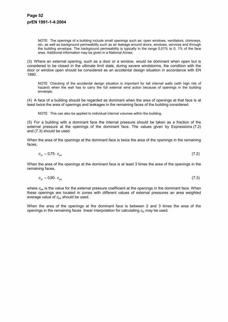
Page 52 prEN 1991-1-4:2004
NOTE The openings of a building include small openings such as: open windows, ventilators, chimneys, etc. as well as background permeability such as air leakage around doors, windows, services and through the building envelope. The background permeability is typically in the range 0,01% to 0, 1% of the face area. Additional information may be given in a National Annex.
(3) Where an external opening, such as a door or a window, would be dominant when open but is considered to be closed in the ultimate limit state, during severe windstorms, the condition with the door or window open should be considered as an accidental design situation in accordance with EN 1990.
NOTE Checking of the accidental design situation is important for tall internal walls (with high risk of hazard) when the wall has to carry the full external wind action because of openings in the building envelope.
(4) A face of a building should be regarded as dominant when the area of openings at that face is at least twice the area of openings and leakages in the remaining faces of the building considered.
NOTE This can also be applied to individual internal volumes within the building.
(5) For a building with a dominant face the internal pressure should be taken as a fraction of the external pressure at the openings of the dominant face. The values given by Expressions (7.2) and (7.3) should be used.
When the area of the openings at the dominant face is twice the area of the openings in the remaining faces,
pepi 75,0 cc ⋅= (7.2)
When the area of the openings at the dominant face is at least 3 times the area of the openings in the remaining faces,
pepi 90,0 cc ⋅= (7.3)
where cpe is the value for the external pressure coefficient at the openings in the dominant face. When these openings are located in zones with different values of external pressures an area weighted average value of cpe should be used.
When the area of the openings at the dominant face is between 2 and 3 times the area of the openings in the remaining faces linear interpolation for calculating cpi may be used.
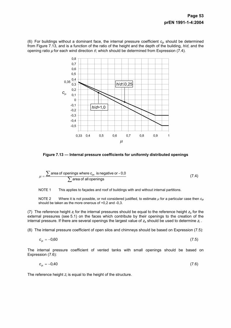
Page 53 prEN 1991-1-4:2004
(6) For buildings without a dominant face, the internal pressure coefficient cpi should be determined from Figure 7.13, and is a function of the ratio of the height and the depth of the building, h/d, and the opening ratio µ for each wind direction θ, which should be determined from Expression (7.4).
Figure 7.13 — Internal pressure coefficients for uniformly distributed openings
∑
∑=openings all of area
0,0- or negative is whereopenings of area pe cµ (7.4)
NOTE 1 This applies to façades and roof of buildings with and without internal partitions.
NOTE 2 Where it is not possible, or not considered justified, to estimate µ for a particular case then cpi should be taken as the more onerous of +0,2 and -0,3.
(7) The reference height zi for the internal pressures should be equal to the reference height ze for the external pressures (see 5.1) on the faces which contribute by their openings to the creation of the internal pressure. If there are several openings the largest value of ze should be used to determine zi .
(8) The internal pressure coefficient of open silos and chimneys should be based on Expression (7.5):
60,0pi −=c (7.5)
The internal pressure coefficient of vented tanks with small openings should be based on Expression (7.6):
40,0pi −=c (7.6)
The reference height Zi is equal to the height of the structure.
Page 54 prEN 1991-1-4:2004
7.2.10 Pressure on walls or roofs with more than one skin
(1) The wind force is to be calculated separately on each skin.
(2) The permeability µ of a skin is defined as the ratio of the total area of the opening to the total area of the skin. A skin is defined as impermeable if the value µ is less than 0,1%.
(3) If only one skin is permeable, then the wind force on the impermeable skin should be determined from the difference between the internal and the external wind pressure as described in Section 5.1. If more than one skin is permeable then the wind force on each skin depends on:
– The relative rigidity of the skins,
– The external and internal pressures,
– The distance between the skins,
– The permeability of the skins,
– The openings at the extremities of the layer between the skins.
NOTE 1 The National Annex may give values for the wind effects on external walls and roofs with more than one skin. As a first approximation it is recommended that the wind pressure on the most rigid skin may be taken as the difference between the internal and the external pressures.
NOTE 2 The National Annex may give rules for cases where the extremities of the layer between the skins are air tight (Figure 7.14(a)) and where the free distance between the skins is less than 100 mm (the thermal insulation material being included in one skin, when there is no airflow within the insulation). As a first approximation the following recommended rules may be applied:
For walls and roofs with an impermeable inside skin and a permeable outside skin with approximately uniformly distributed openings, the wind force on the outside skin may be calculated from cp,net = 2/3 · cpe for overpressure and cp,net = 1/3 · cpe for underpressure. The windforce on the inside skin may be calculated from cp,net = cpe - cpi.
For walls and roofs with an impermeable inside skin and an impermeable more rigid, outside skin, the wind force on the outside skin may be calculated from cp,net = cpe - cpi.
For walls and roofs with a permeable inside skin with approximately uniformly distributed openings and an impermeable outside skin, the wind force on the outside skin may be calculated from cp,net = cpe- cpi , and the wind force on the inside skin from cp,net = 1/3 · cpi.
For walls and roofs with an impermeable outside skin and an impermeable, more rigid inside skin, the wind force on the outside skin may be calculated from cp,net = cpe and the wind force on the inside skin from cp,net = cpe- cpi.
If entries of air put the layer of air into communication with faces of the building other than the face on which the wall is situated (Figure 7.14(b)), these rules are not applicable
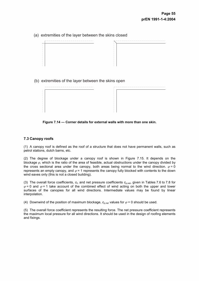
Page 55 prEN 1991-1-4:2004
Figure 7.14 — Corner details for external walls with more than one skin.
7.3 Canopy roofs
(1) A canopy roof is defined as the roof of a structure that does not have permanent walls, such as petrol stations, dutch barns, etc.
(2) The degree of blockage under a canopy roof is shown in Figure 7.15. It depends on the blockage ϕ, which is the ratio of the area of feasible, actual obstructions under the canopy divided by the cross sectional area under the canopy, both areas being normal to the wind direction. ϕ = 0 represents an empty canopy, and ϕ = 1 represents the canopy fully blocked with contents to the down wind eaves only (this is not a closed building).
(3) The overall force coefficients, cf, and net pressure coefficients cp,net, given in Tables 7.6 to 7.8 for ϕ = 0 and ϕ = 1 take account of the combined effect of wind acting on both the upper and lower surfaces of the canopies for all wind directions. Intermediate values may be found by linear interpolation.
(4) Downwind of the position of maximum blockage, cp,net values for ϕ = 0 should be used.
(5) The overall force coefficient represents the resulting force. The net pressure coefficient represents the maximum local pressure for all wind directions. It should be used in the design of roofing elements and fixings.
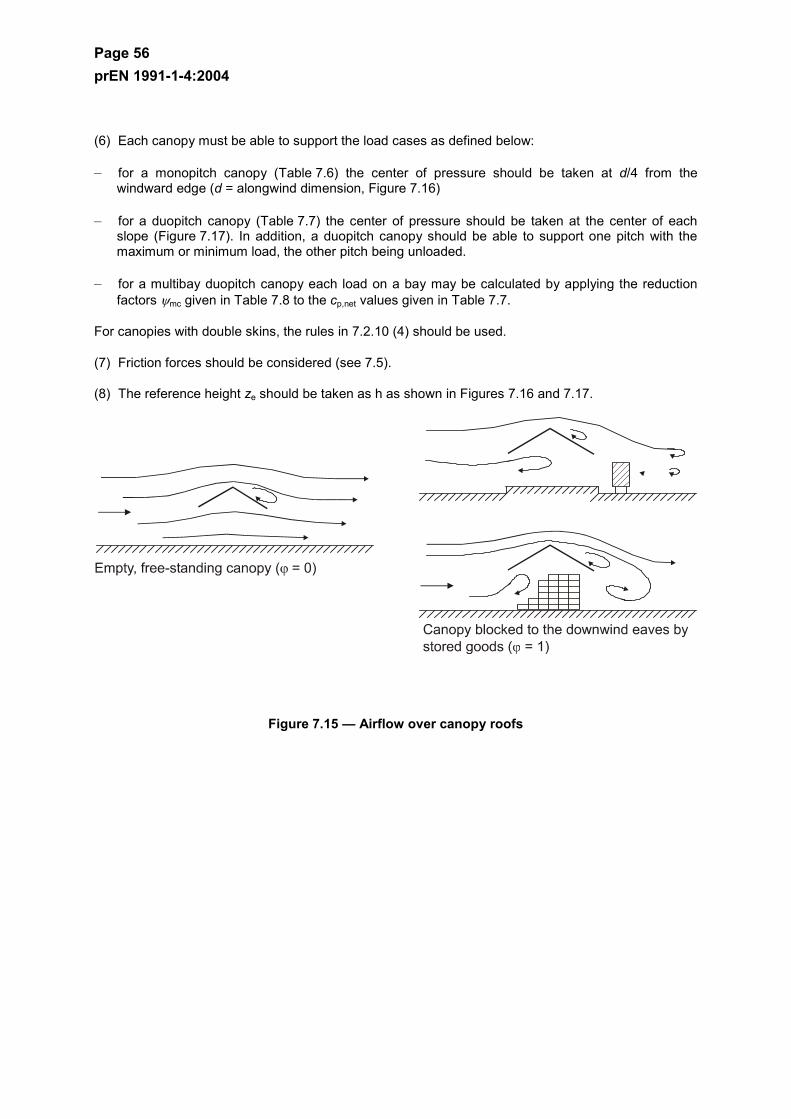
Page 56 prEN 1991-1-4:2004
(6) Each canopy must be able to support the load cases as defined below:
– for a monopitch canopy (Table 7.6) the center of pressure should be taken at d/4 from the windward edge (d = alongwind dimension, Figure 7.16)
– for a duopitch canopy (Table 7.7) the center of pressure should be taken at the center of each slope (Figure 7.17). In addition, a duopitch canopy should be able to support one pitch with the maximum or minimum load, the other pitch being unloaded.
– for a multibay duopitch canopy each load on a bay may be calculated by applying the reduction factors ψmc given in Table 7.8 to the cp,net values given in Table 7.7.
For canopies with double skins, the rules in 7.2.10 (4) should be used.
(7) Friction forces should be considered (see 7.5).
(8) The reference height ze should be taken as h as shown in Figures 7.16 and 7.17.
Figure 7.15 — Airflow over canopy roofs
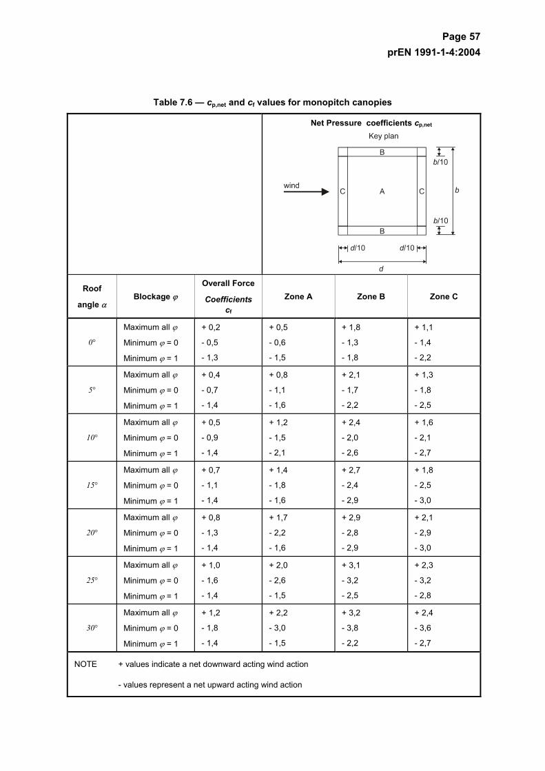
Page 57 prEN 1991-1-4:2004
Table 7.6 — cp,net and cf values for monopitch canopies
Net Pressure coefficients cp,net
Roof
angle α Blockage ϕ
Overall Force
Coefficients cf
Zone A Zone B Zone C
0°
Maximum all ϕ
Minimum ϕ = 0
Minimum ϕ = 1
+ 0,2
- 0,5
- 1,3
+ 0,5
- 0,6
- 1,5
+ 1,8
- 1,3
- 1,8
+ 1,1
- 1,4
- 2,2
5°
Maximum all ϕ
Minimum ϕ = 0
Minimum ϕ = 1
+ 0,4
- 0,7
- 1,4
+ 0,8
- 1,1
- 1,6
+ 2,1
- 1,7
- 2,2
+ 1,3
- 1,8
- 2,5
10°
Maximum all ϕ
Minimum ϕ = 0
Minimum ϕ = 1
+ 0,5
- 0,9
- 1,4
+ 1,2
- 1,5
- 2,1
+ 2,4
- 2,0
- 2,6
+ 1,6
- 2,1
- 2,7
15°
Maximum all ϕ
Minimum ϕ = 0
Minimum ϕ = 1
+ 0,7
- 1,1
- 1,4
+ 1,4
- 1,8
- 1,6
+ 2,7
- 2,4
- 2,9
+ 1,8
- 2,5
- 3,0
20°
Maximum all ϕ
Minimum ϕ = 0
Minimum ϕ = 1
+ 0,8
- 1,3
- 1,4
+ 1,7
- 2,2
- 1,6
+ 2,9
- 2,8
- 2,9
+ 2,1
- 2,9
- 3,0
25°
Maximum all ϕ
Minimum ϕ = 0
Minimum ϕ = 1
+ 1,0
- 1,6
- 1,4
+ 2,0
- 2,6
- 1,5
+ 3,1
- 3,2
- 2,5
+ 2,3
- 3,2
- 2,8
30°
Maximum all ϕ
Minimum ϕ = 0
Minimum ϕ = 1
+ 1,2
- 1,8
- 1,4
+ 2,2
- 3,0
- 1,5
+ 3,2
- 3,8
- 2,2
+ 2,4
- 3,6
- 2,7
NOTE + values indicate a net downward acting wind action
- values represent a net upward acting wind action
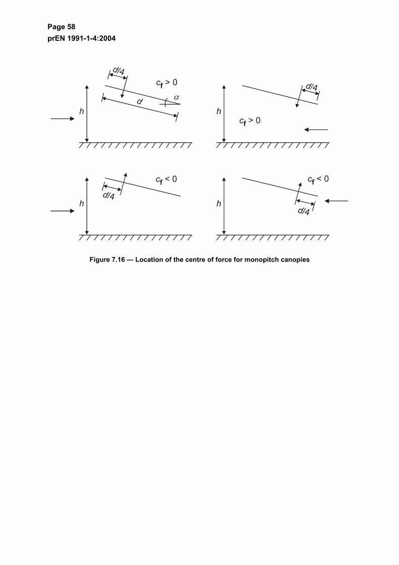
Page 58 prEN 1991-1-4:2004
Figure 7.16 — Location of the centre of force for monopitch canopies
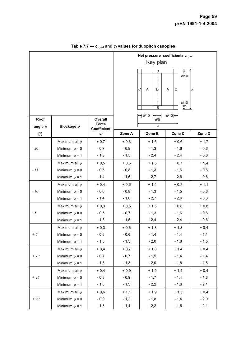
Page 59 prEN 1991-1-4:2004
Table 7.7 — cp,net and cf values for duopitch canopies
Net pressure coefficients cp,net
Roof
angle α
[°]
Blockage ϕ
Overall Force
Coefficientcf Zone A Zone B Zone C Zone D
- 20
Maximum all ϕ
Minimum ϕ = 0
Minimum ϕ = 1
+ 0,7
- 0,7
- 1,3
+ 0,8
- 0,9
- 1,5
+ 1,6
- 1,3
- 2,4
+ 0,6
- 1,6
- 2,4
+ 1,7
- 0,6
- 0,6
- 15
Maximum all ϕ
Minimum ϕ = 0
Minimum ϕ = 1
+ 0,5
- 0,6
- 1,4
+ 0,6
- 0,8
- 1,6
+ 1,5
- 1,3
- 2,7
+ 0,7
- 1,6
- 2,6
+ 1,4
- 0,6
- 0,6
- 10
Maximum all ϕ
Minimum ϕ = 0
Minimum ϕ = 1
+ 0,4
- 0,6
- 1,4
+ 0,6
- 0,8
- 1,6
+ 1,4
- 1,3
- 2,7
+ 0,8
- 1,5
- 2,6
+ 1,1
- 0,6
- 0,6
- 5
Maximum all ϕ
Minimum ϕ = 0
Minimum ϕ = 1
+ 0,3
- 0,5
- 1,3
+ 0,5
- 0,7
- 1,5
+ 1,5
- 1,3
- 2,4
+ 0,8
- 1,6
- 2,4
+ 0,8
- 0,6
- 0,6
+ 5
Maximum all ϕ
Minimum ϕ = 0
Minimum ϕ = 1
+ 0,3
- 0,6
- 1,3
+ 0,6
- 0,6
- 1,3
+ 1,8
- 1,4
- 2,0
+ 1,3
- 1,4
- 1,8
+ 0,4
- 1,1
- 1,5
+ 10
Maximum all ϕ
Minimum ϕ = 0
Minimum ϕ = 1
+ 0,4
- 0,7
- 1,3
+ 0,7
- 0,7
- 1,3
+ 1,8
- 1,5
- 2,0
+ 1,4
- 1,4
- 1,8
+ 0,4
- 1,4
- 1,8
+ 15
Maximum all ϕ
Minimum ϕ = 0
Minimum ϕ = 1
+ 0,4
- 0,8
- 1,3
+ 0,9
- 0,9
- 1,3
+ 1,9
- 1,7
- 2,2
+ 1,4
- 1,4
- 1,6
+ 0,4
- 1,8
- 2,1
+ 20
Maximum all ϕ
Minimum ϕ = 0
Minimum ϕ = 1
+ 0,6
- 0,9
- 1,3
+ 1,1
- 1,2
- 1,4
+ 1,9
- 1,8
- 2,2
+ 1,5
- 1,4
- 1,6
+ 0,4
- 2,0
- 2,1
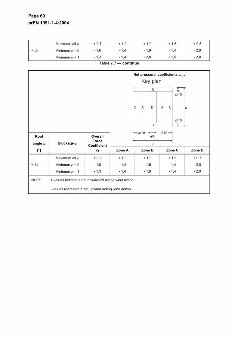
Page 60 prEN 1991-1-4:2004
+ 25
Maximum all ϕ
Minimum ϕ = 0
Minimum ϕ = 1
+ 0,7
- 1,0
- 1,3
+ 1,2
- 1,4
- 1,4
+ 1,9
- 1,9
- 2,0
+ 1,6
- 1,4
- 1,5
+ 0,5
- 2,0
- 2,0
Table 7.7 — continue
Net pressure coefficients cp,net
Roof
angle α
[°]
Blockage ϕ
Overall Force
Coefficientcf Zone A Zone B Zone C Zone D
+ 30
Maximum all ϕ
Minimum ϕ = 0
Minimum ϕ = 1
+ 0,9
- 1,0
- 1,3
+ 1,3
- 1,4
- 1,4
+ 1,9
- 1,9
- 1,8
+ 1,6
- 1,4
- 1,4
+ 0,7
- 2,0
- 2,0
NOTE + values indicate a net downward acting wind action
- values represent a net upward acting wind action
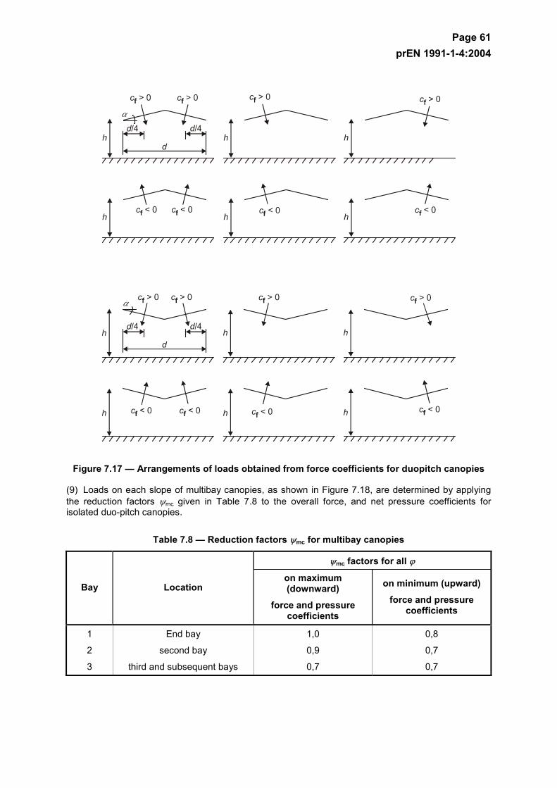
Page 61 prEN 1991-1-4:2004
Figure 7.17 — Arrangements of loads obtained from force coefficients for duopitch canopies
(9) Loads on each slope of multibay canopies, as shown in Figure 7.18, are determined by applying the reduction factors ψmc given in Table 7.8 to the overall force, and net pressure coefficients for isolated duo-pitch canopies.
Table 7.8 — Reduction factors ψmc for multibay canopies
ψmc factors for all ϕ
Bay Location on maximum (downward)
force and pressure coefficients
on minimum (upward)
force and pressure coefficients
1
2
3
End bay
second bay
third and subsequent bays
1,0
0,9
0,7
0,8
0,7
0,7
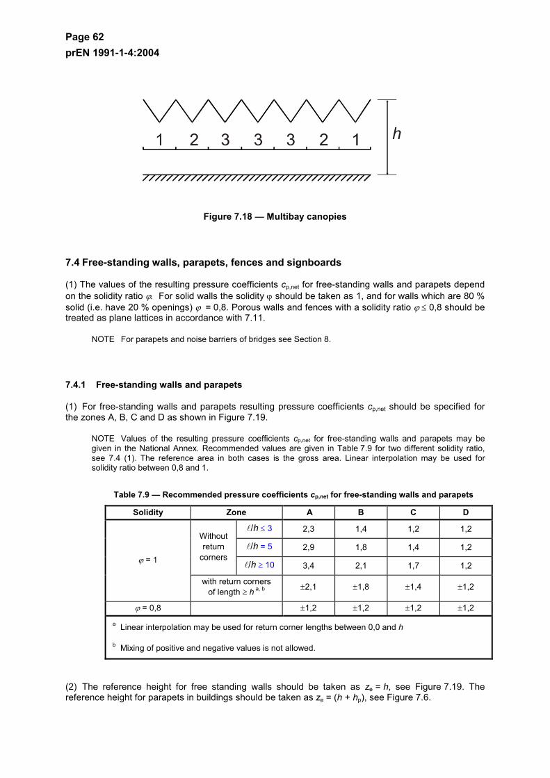
Page 62 prEN 1991-1-4:2004
Figure 7.18 — Multibay canopies
7.4 Free-standing walls, parapets, fences and signboards
(1) The values of the resulting pressure coefficients cp,net for free-standing walls and parapets depend on the solidity ratio ϕ. For solid walls the solidity ϕ should be taken as 1, and for walls which are 80 % solid (i.e. have 20 % openings) ϕ = 0,8. Porous walls and fences with a solidity ratio ϕ ≤ 0,8 should be treated as plane lattices in accordance with 7.11.
NOTE For parapets and noise barriers of bridges see Section 8.
7.4.1 Free-standing walls and parapets
(1) For free-standing walls and parapets resulting pressure coefficients cp,net should be specified for the zones A, B, C and D as shown in Figure 7.19.
NOTE Values of the resulting pressure coefficients cp,net for free-standing walls and parapets may be given in the National Annex. Recommended values are given in Table 7.9 for two different solidity ratio, see 7.4 (1). The reference area in both cases is the gross area. Linear interpolation may be used for solidity ratio between 0,8 and 1.
Table 7.9 — Recommended pressure coefficients cp,net for free-standing walls and parapets
Solidity Zone A B C D
/h ≤ 3 2,3 1,4 1,2 1,2
/h = 5 2,9 1,8 1,4 1,2 Without return
corners /h ≥ 10 3,4 2,1 1,7 1,2
ϕ = 1
with return corners of length ≥ h a, b ±2,1 ±1,8 ±1,4 ±1,2
ϕ = 0,8 ±1,2 ±1,2 ±1,2 ±1,2
a Linear interpolation may be used for return corner lengths between 0,0 and h
b Mixing of positive and negative values is not allowed.
(2) The reference height for free standing walls should be taken as ze = h, see Figure 7.19. The reference height for parapets in buildings should be taken as ze = (h + hp), see Figure 7.6.
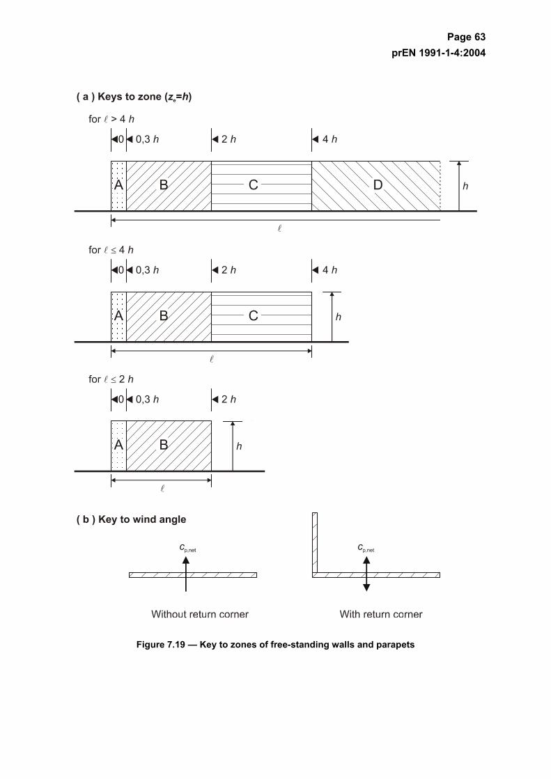
Page 63 prEN 1991-1-4:2004
Figure 7.19 — Key to zones of free-standing walls and parapets
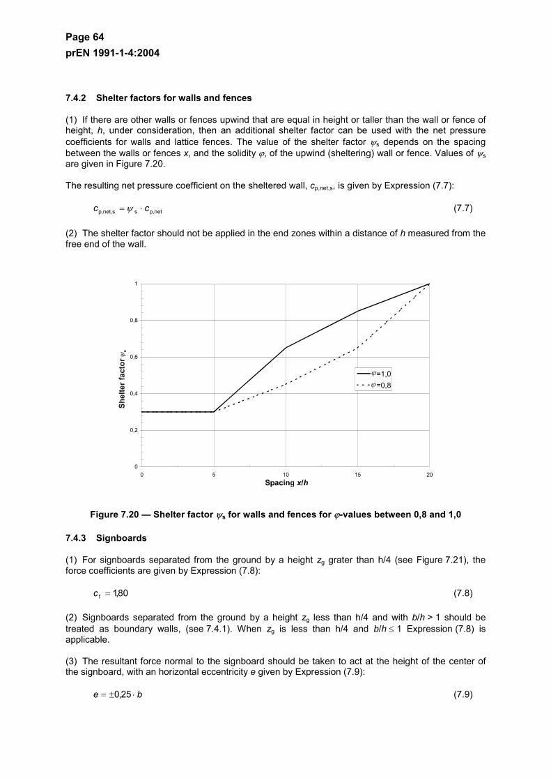
Page 64 prEN 1991-1-4:2004
7.4.2 Shelter factors for walls and fences
(1) If there are other walls or fences upwind that are equal in height or taller than the wall or fence of height, h, under consideration, then an additional shelter factor can be used with the net pressure coefficients for walls and lattice fences. The value of the shelter factor ψs depends on the spacing between the walls or fences x, and the solidity ϕ, of the upwind (sheltering) wall or fence. Values of ψs are given in Figure 7.20.
The resulting net pressure coefficient on the sheltered wall, cp,net,s, is given by Expression (7.7):
netp,snet,sp, cc ⋅= ψ (7.7)
(2) The shelter factor should not be applied in the end zones within a distance of h measured from the free end of the wall.
Figure 7.20 — Shelter factor ψs for walls and fences for ϕ-values between 0,8 and 1,0
7.4.3 Signboards
(1) For signboards separated from the ground by a height zg grater than h/4 (see Figure 7.21), the force coefficients are given by Expression (7.8):
80,1f =c (7.8)
(2) Signboards separated from the ground by a height zg less than h/4 and with b/h > 1 should be treated as boundary walls, (see 7.4.1). When zg is less than h/4 and b/h ≤ 1 Expression (7.8) is applicable.
(3) The resultant force normal to the signboard should be taken to act at the height of the center of the signboard, with an horizontal eccentricity e given by Expression (7.9):
be ⋅±= 25,0 (7.9)
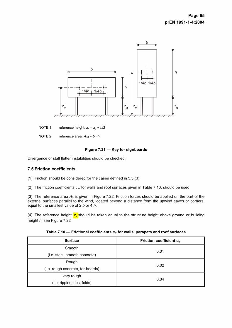
Page 65 prEN 1991-1-4:2004
NOTE 1 reference height: ze = zg + h/2
NOTE 2 reference area: Aref = b · h
Figure 7.21 — Key for signboards
Divergence or stall flutter instabilities should be checked.
7.5 Friction coefficients
(1) Friction should be considered for the cases defined in 5.3 (3).
(2) The friction coefficients cfr, for walls and roof surfaces given in Table 7.10, should be used
(3) The reference area Afr is given in Figure 7.22. Friction forces should be applied on the part of the external surfaces parallel to the wind, located beyond a distance from the upwind eaves or corners, equal to the smallest value of 2·b or 4·h.
(4) The reference height ez should be taken equal to the structure height above ground or building height h, see Figure 7.22
Table 7.10 — Frictional coefficients cfr for walls, parapets and roof surfaces
Surface Friction coefficient cfr
Smooth
(i.e. steel, smooth concrete) 0,01
Rough
(i.e. rough concrete, tar-boards) 0,02
very rough
(i.e. ripples, ribs, folds) 0,04
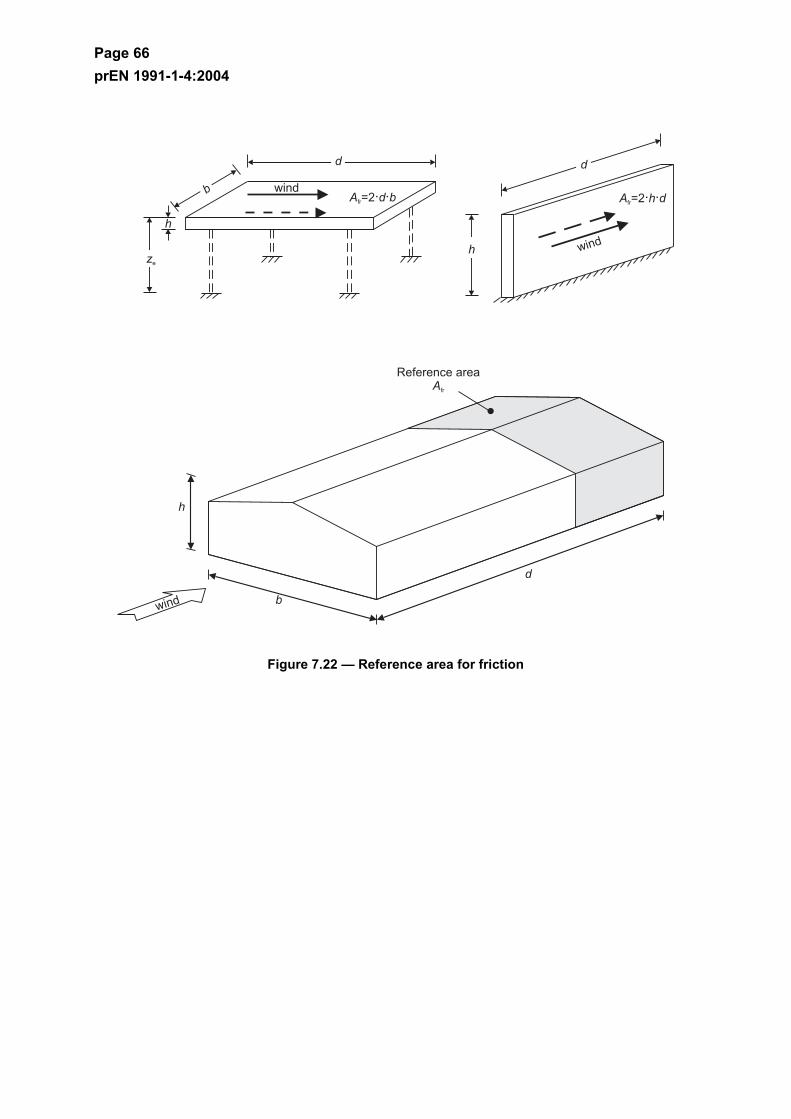
Page 66 prEN 1991-1-4:2004
Figure 7.22 — Reference area for friction
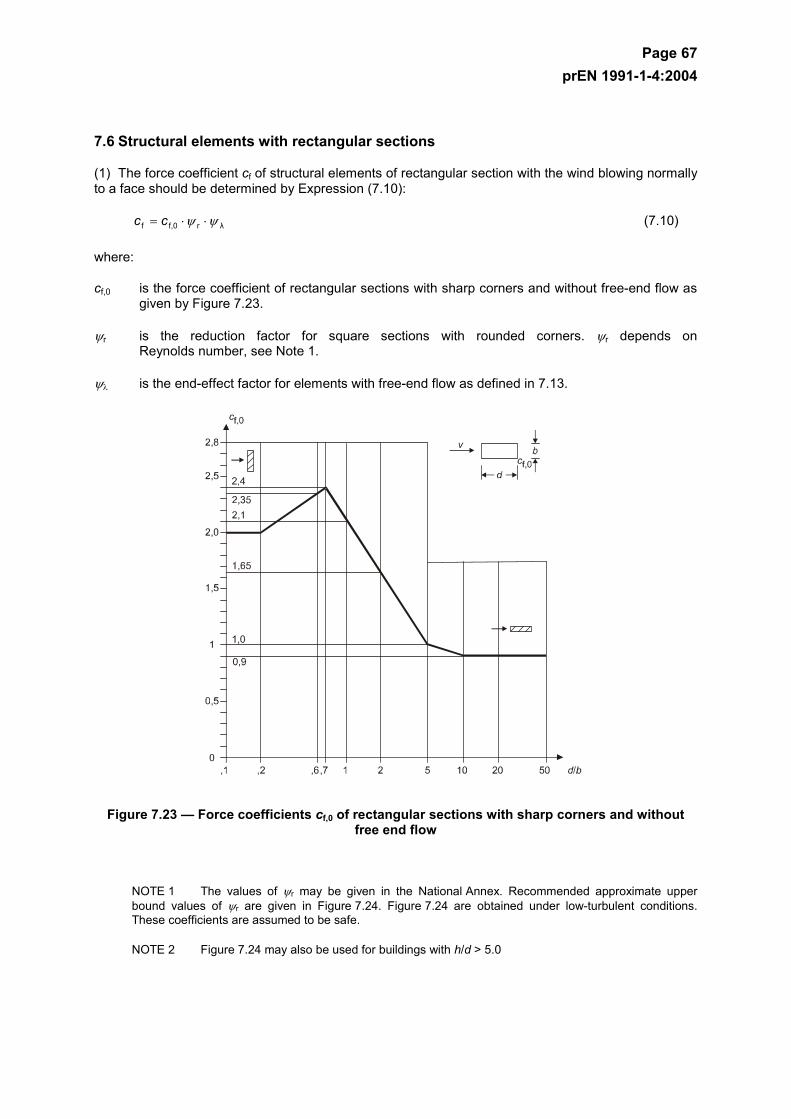
Page 67 prEN 1991-1-4:2004
7.6 Structural elements with rectangular sections
(1) The force coefficient cf of structural elements of rectangular section with the wind blowing normally to a face should be determined by Expression (7.10):
λrf,0f ψψ ⋅⋅= cc (7.10)
where:
cf,0 is the force coefficient of rectangular sections with sharp corners and without free-end flow as given by Figure 7.23.
ψr is the reduction factor for square sections with rounded corners. ψr depends on Reynolds number, see Note 1.
ψλ is the end-effect factor for elements with free-end flow as defined in 7.13.
Figure 7.23 — Force coefficients cf,0 of rectangular sections with sharp corners and without free end flow
NOTE 1 The values of ψr may be given in the National Annex. Recommended approximate upper bound values of ψr are given in Figure 7.24. Figure 7.24 are obtained under low-turbulent conditions. These coefficients are assumed to be safe.
NOTE 2 Figure 7.24 may also be used for buildings with h/d > 5.0
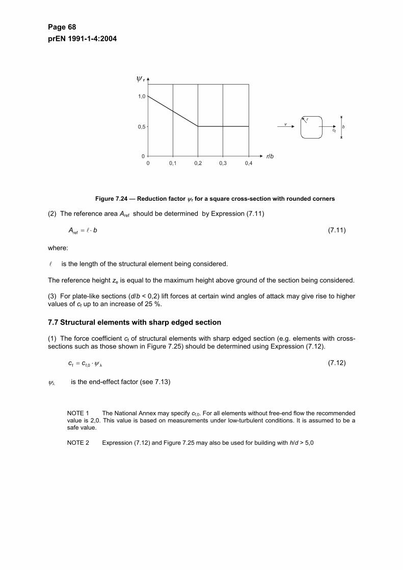
Page 68 prEN 1991-1-4:2004
Figure 7.24 — Reduction factor ψr for a square cross-section with rounded corners
(2) The reference area Aref should be determined by Expression (7.11)
bA ⋅=ref (7.11)
where:
is the length of the structural element being considered.
The reference height ze is equal to the maximum height above ground of the section being considered.
(3) For plate-like sections (d/b < 0,2) lift forces at certain wind angles of attack may give rise to higher values of cf up to an increase of 25 %.
7.7 Structural elements with sharp edged section
(1) The force coefficient cf of structural elements with sharp edged section (e.g. elements with cross- sections such as those shown in Figure 7.25) should be determined using Expression (7.12).
λf,0f ψ⋅= cc (7.12)
ψλ is the end-effect factor (see 7.13)
NOTE 1 The National Annex may specify cf,0. For all elements without free-end flow the recommended value is 2,0. This value is based on measurements under low-turbulent conditions. It is assumed to be a safe value.
NOTE 2 Expression (7.12) and Figure 7.25 may also be used for building with h/d > 5,0
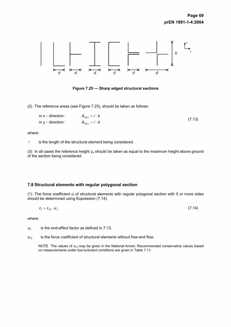
Page 69 prEN 1991-1-4:2004
Figure 7.25 — Sharp edged structural sections
(2) The reference areas (see Figure 7.25), should be taken as follows:
dAbA
⋅=−
⋅=−
yref,
xref,
:directionyin:directionxin
(7.13)
where:
is the length of the structural element being considered.
(3) In all cases the reference height ze should be taken as equal to the maximum height above ground of the section being considered.
7.8 Structural elements with regular polygonal section
(1) The force coefficient cf of structural elements with regular polygonal section with 5 or more sides should be determined using Expression (7.14).
λf,0f ψ⋅= cc (7.14)
where:
ψλ is the end-effect factor as defined in 7.13.
cf,0 is the force coefficient of structural elements without free-end flow.
NOTE The values of cf,0 may be given in the National Annex. Recommended conservative values based on measurements under low-turbulent conditions are given in Table 7.11.
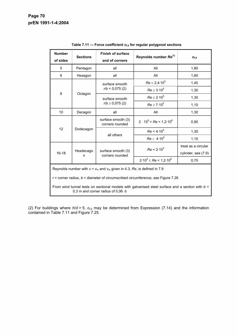
Page 70 prEN 1991-1-4:2004
Table 7.11 — Force coefficient cf,0 for regular polygonal sections
Number
of sides Sections
Finish of surface
and of corners Reynolds number Re(1) cf,0
5 Pentagon all All 1,80
6 Hexagon all All 1,60
Re ≤ 2,4⋅105 1,45 surface smooth r/b < 0,075 (2) Re ≥ 3⋅105 1,30
Re ≤ 2⋅105 1,30 8 Octagon
surface smooth r/b ≥ 0,075 (2) Re ≥ 7⋅105 1,10
10 Decagon all All 1,30
surface smooth (3) corners rounded 2 ⋅ 105 < Re < 1,2⋅106 0,90
Re < 4⋅105 1,30 12 Dodecagon
all others Re > 4⋅105 1,10
Re < 2⋅105 treat as a circular
cylinder, see (7.9) 16-18 Hexdecagon
surface smooth (3) corners rounded
2⋅105 ≤ Re < 1,2⋅106 0,70
Reynolds number with v = vm and vm given in 4.3, Re, is defined in 7.9
r = corner radius, b = diameter of circumscribed circumference, see Figure 7.26
From wind tunnel tests on sectional models with galvanised steel surface and a section with b = 0,3 m and corner radius of 0,06⋅ b
(2) For buildings where h/d > 5, cf,0 may be determined from Expression (7.14) and the information contained in Table 7.11 and Figure 7.25.
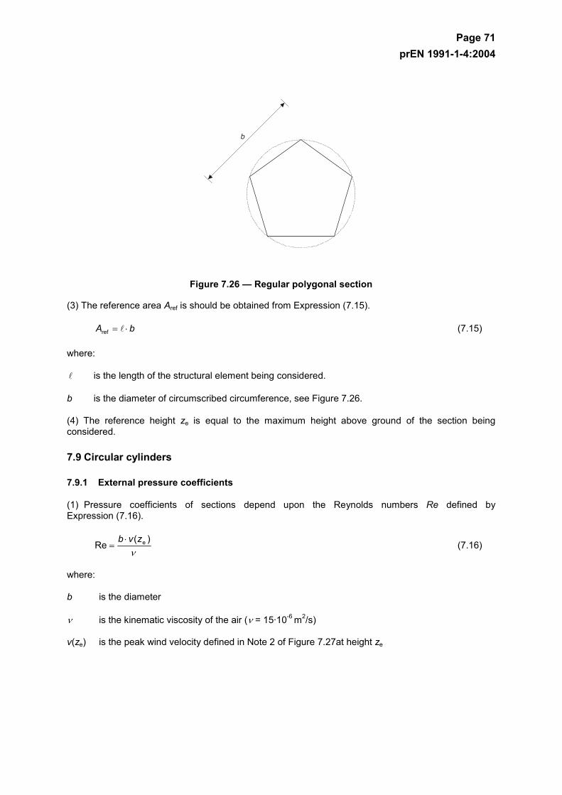
Page 71 prEN 1991-1-4:2004
Figure 7.26 — Regular polygonal section
(3) The reference area Aref is should be obtained from Expression (7.15).
bA ⋅=ref (7.15)
where:
is the length of the structural element being considered.
b is the diameter of circumscribed circumference, see Figure 7.26.
(4) The reference height ze is equal to the maximum height above ground of the section being considered.
7.9 Circular cylinders
7.9.1 External pressure coefficients
(1) Pressure coefficients of sections depend upon the Reynolds numbers Re defined by Expression (7.16).
ν
)(Re ezvb ⋅
= (7.16)
where:
b is the diameter
ν is the kinematic viscosity of the air (ν = 15·10-6 m2/s)
v(ze) is the peak wind velocity defined in Note 2 of Figure 7.27at height ze
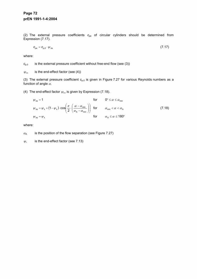
Page 72 prEN 1991-1-4:2004
(2) The external pressure coefficients cpe of circular cylinders should be determined from Expression (7.17).
λαp,0pe ψ⋅= cc (7.17)
where:
cp,0 is the external pressure coefficient without free-end flow (see (3))
ψλα is the end-effect factor (see (4))
(3) The external pressure coefficient cp,0 is given in Figure 7.27 for various Reynolds numbers as a function of angle α.
(4) The end-effect factor ψλα is given by Expression (7.18).
( )
°≤≤=
<<
−
−⋅⋅−+=
≤≤°=
180for
for2
cos1
0for1
Aλλα
AminminA
minλλλα
minλα
ααψψ
αααααααπ
ψψψ
ααψ
(7.18)
where:
αA is the position of the flow separation (see Figure 7.27)
ψλ is the end-effect factor (see 7.13)
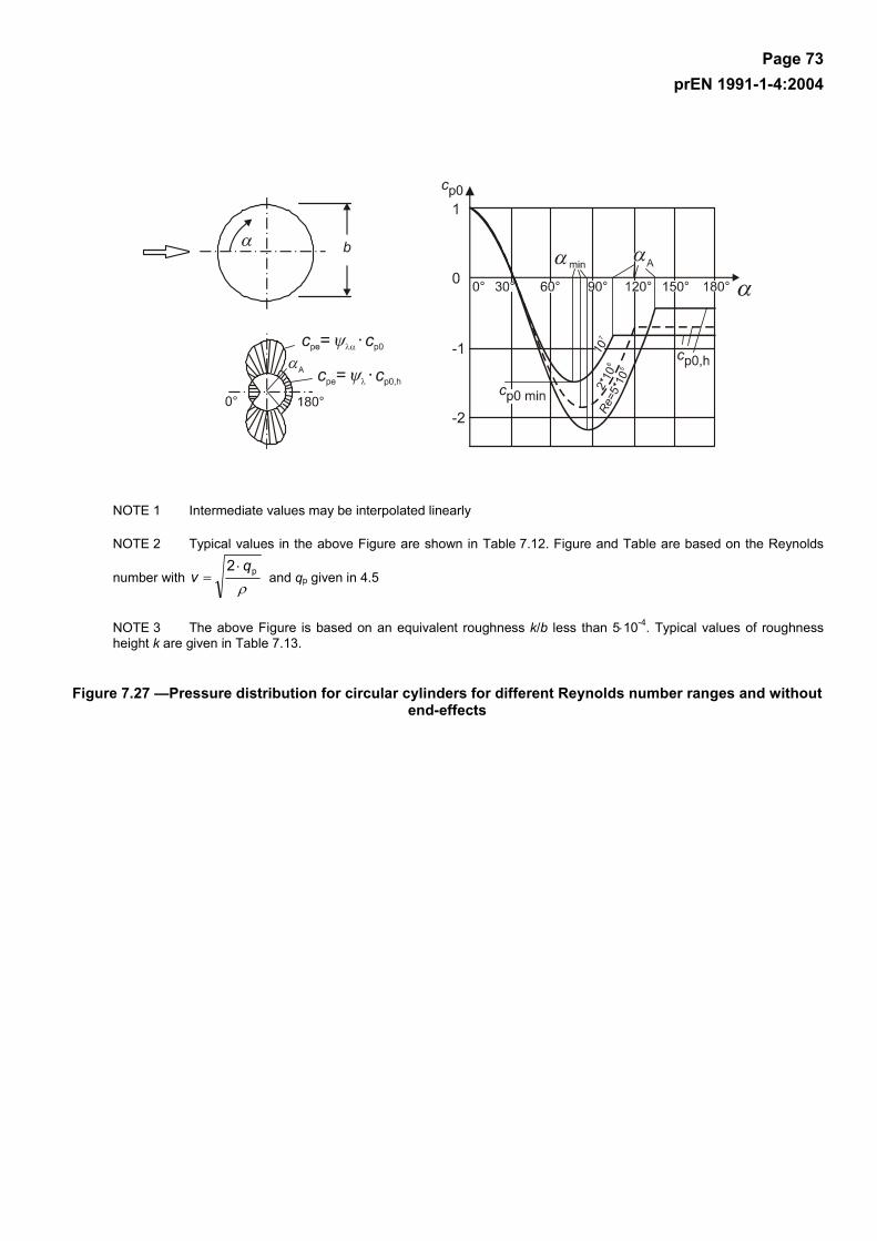
Page 73 prEN 1991-1-4:2004
NOTE 1 Intermediate values may be interpolated linearly
NOTE 2 Typical values in the above Figure are shown in Table 7.12. Figure and Table are based on the Reynolds
number with ρ
p2 qv
⋅= and qp given in 4.5
NOTE 3 The above Figure is based on an equivalent roughness k/b less than 5⋅10-4. Typical values of roughness height k are given in Table 7.13.
Figure 7.27 —Pressure distribution for circular cylinders for different Reynolds number ranges and without end-effects
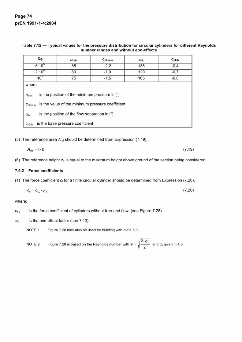
Page 74 prEN 1991-1-4:2004
Table 7.12 — Typical values for the pressure distribution for circular cylinders for different Reynolds number ranges and without end-effects
Re αmin cp0,min αA cp0,h 5·105 85 -2,2 135 -0,4 2·106 80 -1,9 120 -0,7 107 75 -1,5 105 -0,8
where:
αmin is the position of the minimum pressure in [°]
cp0,min is the value of the minimum pressure coefficient
αA is the position of the flow separation in [°]
cp0,h is the base pressure coefficient
(5) The reference area Aref should be determined from Expression (7.19):
bA ⋅=ref (7.19)
(6) The reference height ze is equal to the maximum height above ground of the section being considered.
7.9.2 Force coefficients
(1) The force coefficient cf for a finite circular cylinder should be determined from Expression (7.20).
λf,0f ψ⋅= cc (7.20)
where:
cf,0 is the force coefficient of cylinders without free-end flow (see Figure 7.28)
ψλ is the end-effect factor (see 7.13)
NOTE 1 Figure 7.28 may also be used for building with h/d > 5.0
NOTE 2 Figure 7.28 is based on the Reynolds number with ρ
p2 qv
⋅= and qp given in 4.5
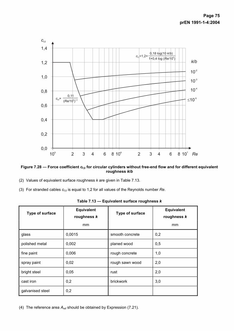
Page 75 prEN 1991-1-4:2004
Figure 7.28 — Force coefficient cf,0 for circular cylinders without free-end flow and for different equivalent roughness k/b
(2) Values of equivalent surface roughness k are given in Table 7.13.
(3) For stranded cables cf,0 is equal to 1,2 for all values of the Reynolds number Re.
Table 7.13 — Equivalent surface roughness k
Type of surface Equivalent
roughness k Type of surface
Equivalent
roughness k
mm mm
glass 0,0015 smooth concrete 0,2
polished metal 0,002 planed wood 0,5
fine paint 0,006 rough concrete 1,0
spray paint 0,02 rough sawn wood 2,0
bright steel 0,05 rust 2,0
cast iron 0,2 brickwork 3,0
galvanised steel 0,2
(4) The reference area Aref should be obtained by Expression (7.21).
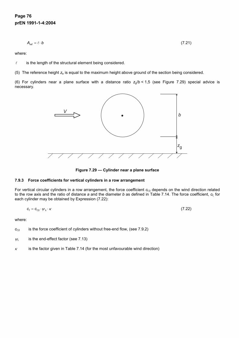
Page 76 prEN 1991-1-4:2004
bA ⋅=ref (7.21)
where:
is the length of the structural element being considered.
(5) The reference height ze is equal to the maximum height above ground of the section being considered.
(6) For cylinders near a plane surface with a distance ratio zg/b < 1,5 (see Figure 7.29) special advice is necessary.
Figure 7.29 — Cylinder near a plane surface
7.9.3 Force coefficients for vertical cylinders in a row arrangement
For vertical circular cylinders in a row arrangement, the force coefficient cf,0 depends on the wind direction related to the row axis and the ratio of distance a and the diameter b as defined in Table 7.14. The force coefficient, cf, for each cylinder may be obtained by Expression (7.22):
κψ ⋅⋅= λf,0f cc (7.22)
where:
cf,0 is the force coefficient of cylinders without free-end flow, (see 7.9.2)
ψλ is the end-effect factor (see 7.13)
κ is the factor given in Table 7.14 (for the most unfavourable wind direction)
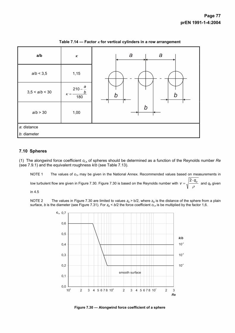
Page 77 prEN 1991-1-4:2004
Table 7.14 — Factor κ for vertical cylinders in a row arrangement
a/b κ
a/b < 3,5 1,15
3,5 < a/b < 30 180
210ba
−=κ
a/b > 30 1,00
a: distance
b: diameter
7.10 Spheres
(1) The alongwind force coefficient cf,x of spheres should be determined as a function of the Reynolds number Re (see 7.9.1) and the equivalent roughness k/b (see Table 7.13).
NOTE 1 The values of cf,x may be given in the National Annex. Recommended values based on measurements in
low turbulent flow are given in Figure 7.30. Figure 7.30 is based on the Reynolds number with ρ
p2 qv
⋅= and qp given
in 4.5
NOTE 2 The values in Figure 7.30 are limited to values zg > b/2, where zg is the distance of the sphere from a plain surface, b is the diameter (see Figure 7.31). For zg < b/2 the force coefficient cf,x is be multiplied by the factor 1,6.
Figure 7.30 — Alongwind force coefficient of a sphere
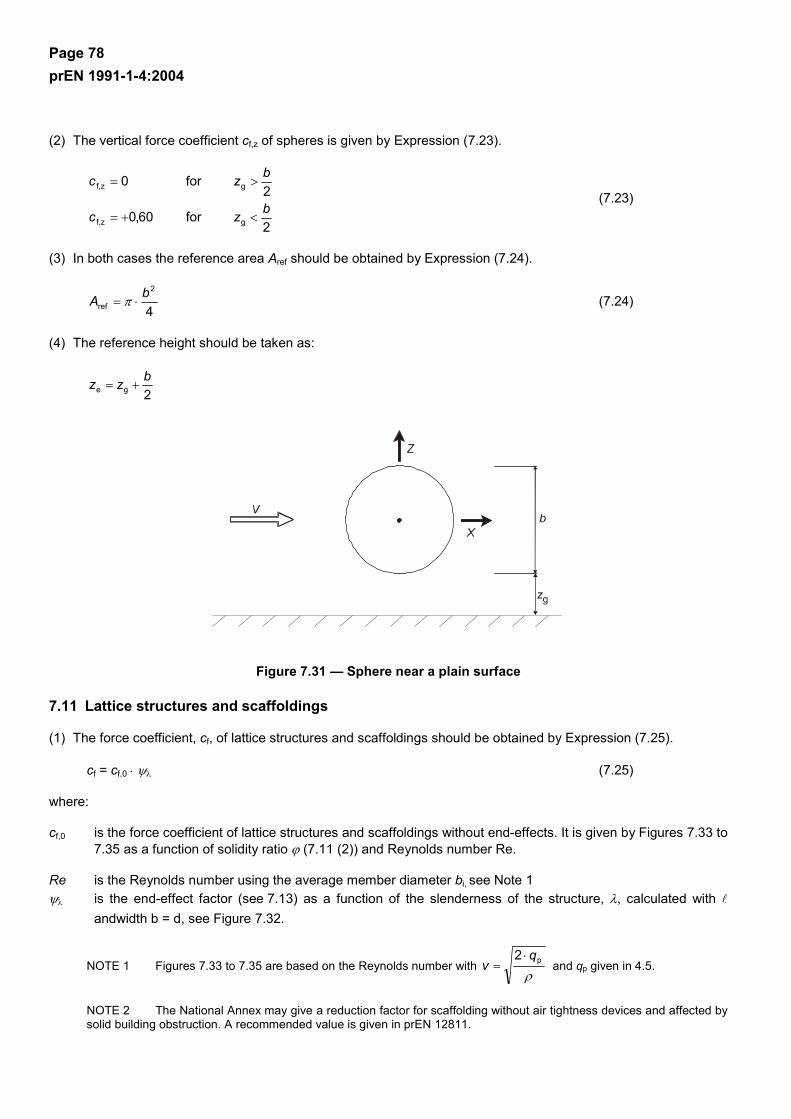
Page 78 prEN 1991-1-4:2004
(2) The vertical force coefficient cf,z of spheres is given by Expression (7.23).
2for60,0
2for0
gf,z
gf,z
bzc
bzc
<+=
>= (7.23)
(3) In both cases the reference area Aref should be obtained by Expression (7.24).
4
2
refbA ⋅= π (7.24)
(4) The reference height should be taken as:
2gebzz +=
Figure 7.31 — Sphere near a plain surface
7.11 Lattice structures and scaffoldings
(1) The force coefficient, cf, of lattice structures and scaffoldings should be obtained by Expression (7.25).
cf = cf,0 ⋅ ψλ (7.25)
where:
cf,0 is the force coefficient of lattice structures and scaffoldings without end-effects. It is given by Figures 7.33 to 7.35 as a function of solidity ratio ϕ (7.11 (2)) and Reynolds number Re.
Re is the Reynolds number using the average member diameter bi, see Note 1
ψλ is the end-effect factor (see 7.13) as a function of the slenderness of the structure, λ, calculated with andwidth b = d, see Figure 7.32.
NOTE 1 Figures 7.33 to 7.35 are based on the Reynolds number with ρ
p2 qv
⋅= and qp given in 4.5.
NOTE 2 The National Annex may give a reduction factor for scaffolding without air tightness devices and affected by solid building obstruction. A recommended value is given in prEN 12811.
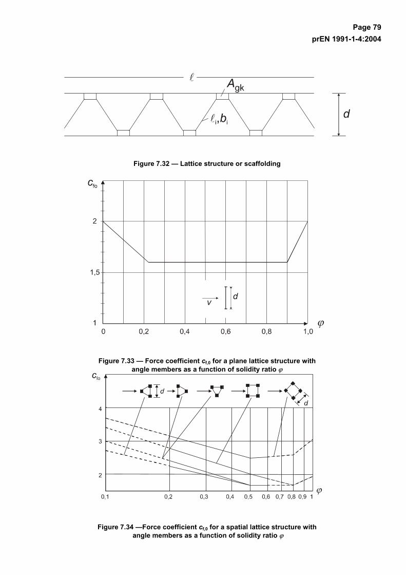
Page 79 prEN 1991-1-4:2004
Figure 7.32 — Lattice structure or scaffolding
Figure 7.33 — Force coefficient cf,0 for a plane lattice structure with angle members as a function of solidity ratio ϕ
Figure 7.34 —Force coefficient cf,0 for a spatial lattice structure with angle members as a function of solidity ratio ϕ
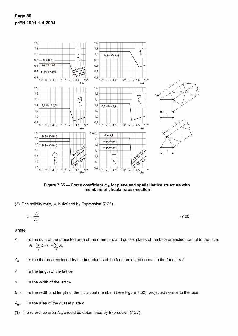
Page 80 prEN 1991-1-4:2004
Figure 7.35 — Force coefficient cf,0 for plane and spatial lattice structure with members of circular cross-section
(2) The solidity ratio, ϕ, is defined by Expression (7.26).
cA
A=ϕ (7.26)
where:
A is the sum of the projected area of the members and gusset plates of the face projected normal to the face:
∑∑ +⋅=k
gkii
i AbA
Ac is the the area enclosed by the boundaries of the face projected normal to the face = d
is the length of the lattice
d is the width of the lattice
bi, i is the width and length of the individual member i (see Figure 7.32), projected normal to the face
Agk is the area of the gusset plate k
(3) The reference area Aref should be determined by Expression (7.27)

Page 81 prEN 1991-1-4:2004
AA =ref (7.27)
(4) The reference height ze is equal to the maximum height of the element above ground.
7.12 Flags
(1) Force coefficients cf and reference areas Aref for flags are given in Table 7.15.
(2) The reference height ze is equal to the height of the flag above ground.
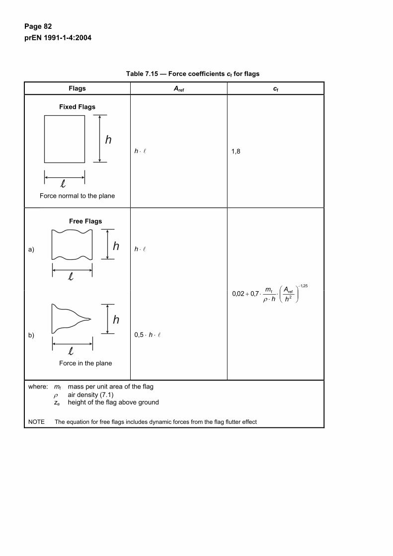
Page 82 prEN 1991-1-4:2004
Table 7.15 — Force coefficients cf for flags
Flags Aref cf
Fixed Flags
Force normal to the plane
h ⋅ 1,8
a)
Free Flags
h
h ⋅
b)
Force in the plane
0,5 ⋅ h ⋅
25,1
2reff7,002,0
−
⋅
⋅⋅+
hA
hmρ
where: mf mass per unit area of the flag ρ air density (7.1) ze height of the flag above ground
NOTE The equation for free flags includes dynamic forces from the flag flutter effect
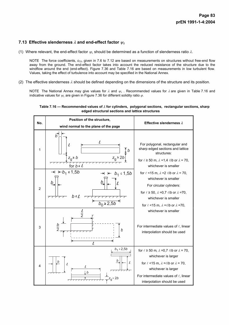
Page 83 prEN 1991-1-4:2004
7.13 Effective slenderness λ and end-effect factor ψλ
(1) Where relevant, the end-effect factor ψλ should be determined as a function of slenderness ratio λ.
NOTE The force coefficients, cf,0, given in 7.6 to 7.12 are based on measurements on structures without free-end flow away from the ground. The end-effect factor takes into account the reduced resistance of the structure due to the windflow around the end (end-effect). Figure 7.36 and Table 7.16 are based on measurements in low turbulent flow. Values, taking the effect of turbulence into account may be specified in the National Annex.
(2) The effective slenderness λ should be defined depending on the dimensions of the structure and its position.
NOTE The National Annex may give values for λ and ψλ . Recommended values for λ are given in Table 7.16 and indicative values for ψλ are given in Figure 7.36 for different solidity ratio ϕ.
Table 7.16 — Recommended values of λ for cylinders, polygonal sections, rectangular sections, sharp edged structural sections and lattice structures
No. Position of the structure,
wind normal to the plane of the page Effective slenderness λ
1
2
3
For polygonal, rectangular and sharp edged sections and lattice
structures:
for ≥ 50 m, λ =1,4 /b or λ = 70, whichever is smaller
for <15 m, λ =2 /b or λ = 70, whichever is smaller
For circular cylinders:
for ≥ 50, λ =0,7 /b or λ =70, whichever is smaller
for <15 m, λ = /b or λ =70, whichever is smaller
For intermediate values of , linear interpolation should be used
4
for ≥ 50 m, λ =0,7 /b or λ = 70, whichever is larger
for <15 m, λ = /b or λ = 70, whichever is larger
For intermediate values of , linear interpolation should be used
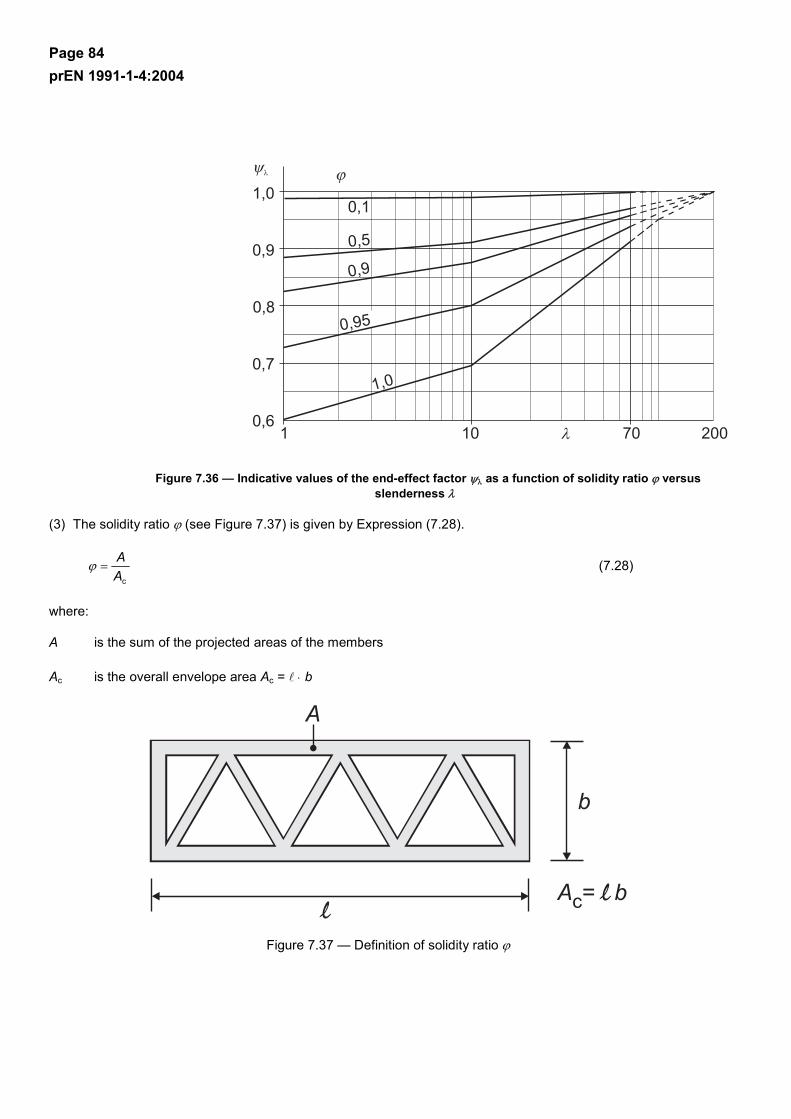
Page 84 prEN 1991-1-4:2004
Figure 7.36 — Indicative values of the end-effect factor ψλ as a function of solidity ratio ϕ versus slenderness λ
(3) The solidity ratio ϕ (see Figure 7.37) is given by Expression (7.28).
cA
A=ϕ (7.28)
where:
A is the sum of the projected areas of the members
Ac is the overall envelope area Ac = ⋅ b
Figure 7.37 — Definition of solidity ratio ϕ

Page 85 prEN 1991-1-4:2004
8 Wind actions on bridges
8.1 General
(1) This section only applies to bridges of constant depth and with cross-sections as shown in Figure 8.1 consisting of a single deck with one or more spans.
NOTE 1 Wind actions for other types of bridges (e.g. arch bridges, bridges with suspension cables or cable stayed, roofed bridges, moving bridges and bridges with multiple or significantly curved decks) may be defined in the National Annex.
NOTE 2 The angle of the wind direction to the deck axis in the vertical and horisontal planes may be defined in the National Annex.
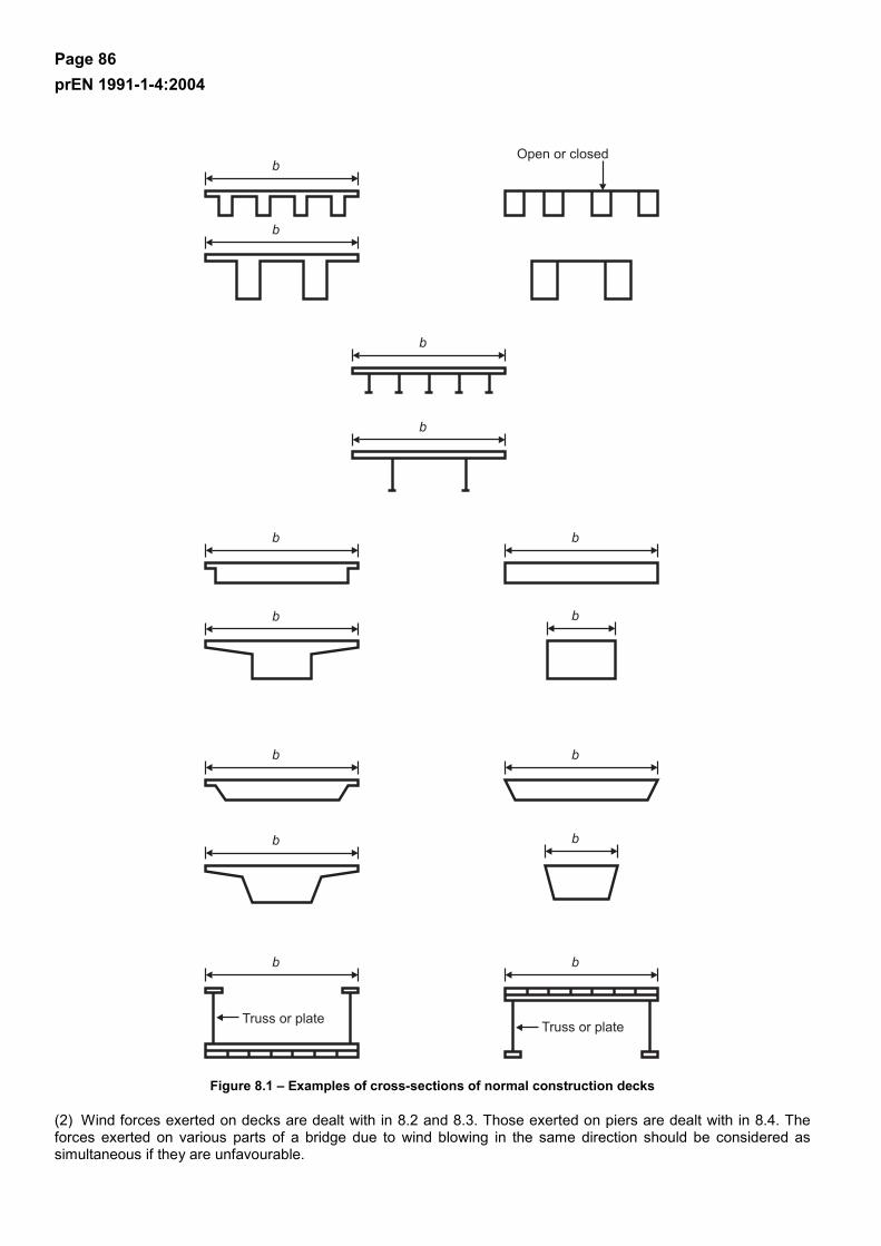
Page 86 prEN 1991-1-4:2004
Figure 8.1 – Examples of cross-sections of normal construction decks
(2) Wind forces exerted on decks are dealt with in 8.2 and 8.3. Those exerted on piers are dealt with in 8.4. The forces exerted on various parts of a bridge due to wind blowing in the same direction should be considered as simultaneous if they are unfavourable.
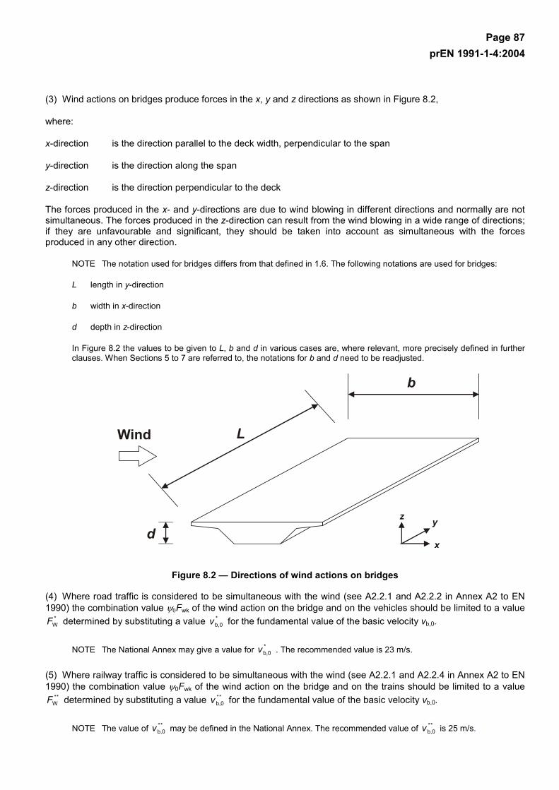
Page 87 prEN 1991-1-4:2004
(3) Wind actions on bridges produce forces in the x, y and z directions as shown in Figure 8.2,
where:
x-direction is the direction parallel to the deck width, perpendicular to the span
y-direction is the direction along the span
z-direction is the direction perpendicular to the deck
The forces produced in the x- and y-directions are due to wind blowing in different directions and normally are not simultaneous. The forces produced in the z-direction can result from the wind blowing in a wide range of directions; if they are unfavourable and significant, they should be taken into account as simultaneous with the forces produced in any other direction.
NOTE The notation used for bridges differs from that defined in 1.6. The following notations are used for bridges:
L length in y-direction
b width in x-direction
d depth in z-direction
In Figure 8.2 the values to be given to L, b and d in various cases are, where relevant, more precisely defined in further clauses. When Sections 5 to 7 are referred to, the notations for b and d need to be readjusted.
Figure 8.2 — Directions of wind actions on bridges
(4) Where road traffic is considered to be simultaneous with the wind (see A2.2.1 and A2.2.2 in Annex A2 to EN 1990) the combination value ψ0Fwk of the wind action on the bridge and on the vehicles should be limited to a value
*WF determined by substituting a value *
b,0v for the fundamental value of the basic velocity vb,0.
NOTE The National Annex may give a value for *b,0v . The recommended value is 23 m/s.
(5) Where railway traffic is considered to be simultaneous with the wind (see A2.2.1 and A2.2.4 in Annex A2 to EN 1990) the combination value ψ0Fwk of the wind action on the bridge and on the trains should be limited to a value
**WF determined by substituting a value **
b,0v for the fundamental value of the basic velocity vb,0.
NOTE The value of **b,0v may be defined in the National Annex. The recommended value of **
b,0v is 25 m/s.

Page 88 prEN 1991-1-4:2004
8.2 Choice of the response calculation procedure
(1) It should be assessed whether a dynamic response procedure is needed for bridges.
NOTE 1 The National Annex may give criteria and procedures.
NOTE 2 If a dynamic response procedure is not needed, cscd may be taken equal to 1,0.
NOTE 3 For normal road and railway bridge decks of less than 40 m span a dynamic response procedure is generally not needed. For the purpose of this categorization, normal bridges may be considered to include bridges constructed in steel, concrete, aluminium or timber, including composite construction, and whose shape of cross sections is generally covered by Figure 8.1.
8.3 Force coefficients
(1) Force coeffcients for parapets and gantries on bridges should be determined were relevant.
NOTE The National Annex may give force coefficients for parapets and gantries on bridges. It is recommended to use Section 7.4.
8.3.1 Force coefficients in x-direction (general method)
(1) Force coefficients for wind actions on bridge decks in the x-direction are given by :
fx,0xf, cc = (8.1)
where:
cfx,0 is the force coefficient without free-end flow (see 7.13).
NOTE 1 A bridge has usually no free-end flow because the flow is deviated only along two sides (over and under the bridge deck).
NOTE 2 For normal bridges cfx,0 may be taken equal to 1,3. Alternatively, cfx,0 may be taken from Figure 8.3.
NOTE 3 Where the angle of inclination of the wind exceeds 10°, the drag coefficient may be derived from special studies. This angle of inclination may be due to the slope of the terrain in the on-coming wind direction.
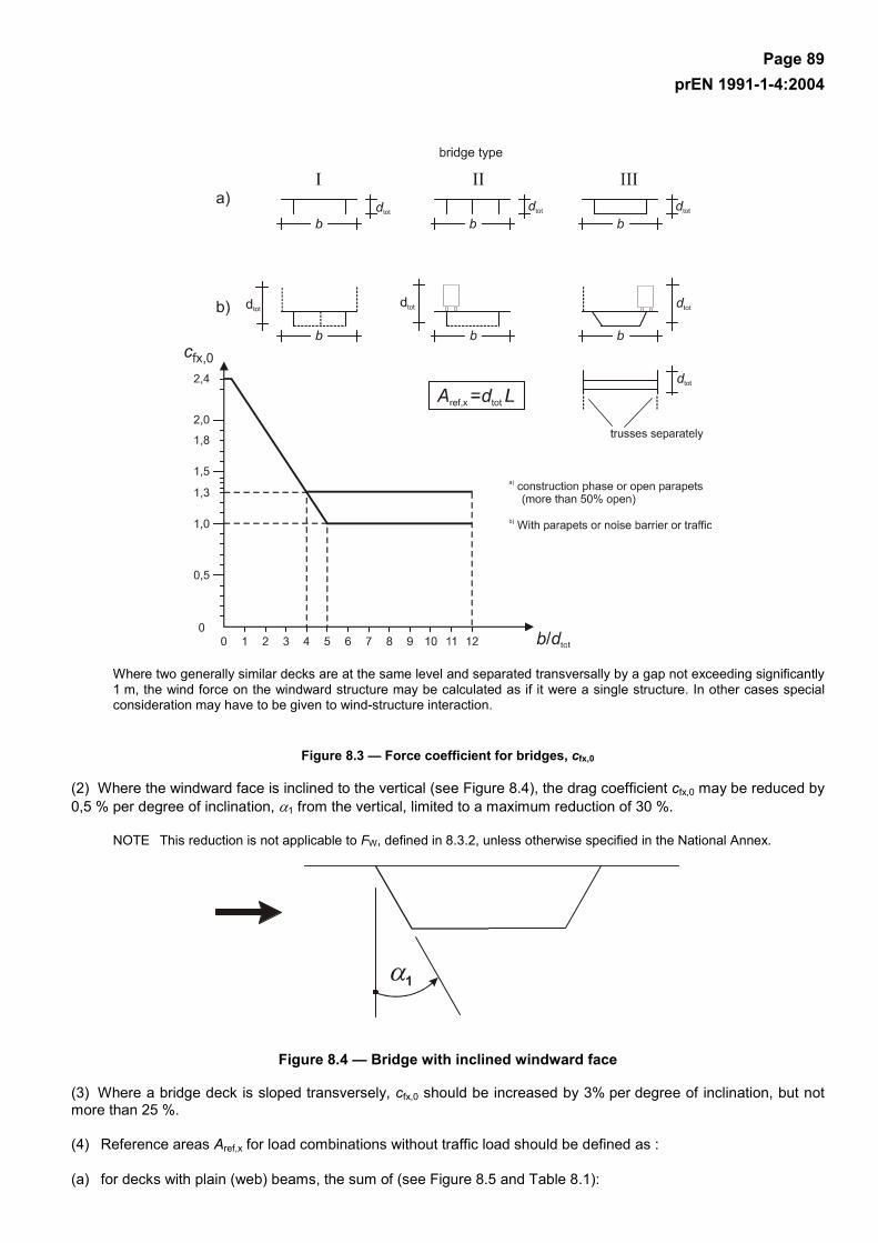
Page 89 prEN 1991-1-4:2004
Where two generally similar decks are at the same level and separated transversally by a gap not exceeding significantly 1 m, the wind force on the windward structure may be calculated as if it were a single structure. In other cases special consideration may have to be given to wind-structure interaction.
Figure 8.3 — Force coefficient for bridges, cfx,0
(2) Where the windward face is inclined to the vertical (see Figure 8.4), the drag coefficient cfx,0 may be reduced by 0,5 % per degree of inclination, α1 from the vertical, limited to a maximum reduction of 30 %.
NOTE This reduction is not applicable to FW, defined in 8.3.2, unless otherwise specified in the National Annex.
Figure 8.4 — Bridge with inclined windward face
(3) Where a bridge deck is sloped transversely, cfx,0 should be increased by 3% per degree of inclination, but not more than 25 %.
(4) Reference areas Aref,x for load combinations without traffic load should be defined as :
(a) for decks with plain (web) beams, the sum of (see Figure 8.5 and Table 8.1):
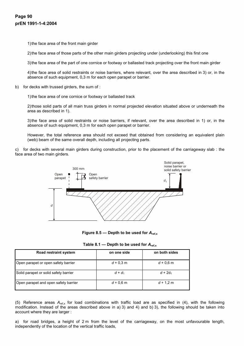
Page 90 prEN 1991-1-4:2004
1) the face area of the front main girder
2) the face area of those parts of the other main girders projecting under (underlooking) this first one
3) the face area of the part of one cornice or footway or ballasted track projecting over the front main girder
4) the face area of solid restraints or noise barriers, where relevant, over the area described in 3) or, in the absence of such equipment, 0,3 m for each open parapet or barrier.
b) for decks with trussed girders, the sum of :
1) the face area of one cornice or footway or ballasted track
2) those solid parts of all main truss girders in normal projected elevation situated above or underneath the area as described in 1).
3) the face area of solid restraints or noise barriers, if relevant, over the area described in 1) or, in the absence of such equipment, 0,3 m for each open parapet or barrier.
However, the total reference area should not exceed that obtained from considering an equivalent plain (web) beam of the same overall depth, including all projecting parts.
c) for decks with several main girders during construction, prior to the placement of the carriageway slab : the face area of two main girders.
Figure 8.5 — Depth to be used for Aref,x
Table 8.1 — Depth to be used for Aref,x
Road restraint system on one side on both sides
Open parapet or open safety barrier d + 0,3 m d + 0,6 m
Solid parapet or solid safety barrier d + d1 d + 2d1
Open parapet and open safety barrier d + 0,6 m d + 1,2 m
(5) Reference areas Aref,x for load combinations with traffic load are as specified in (4), with the following modification. Instead of the areas described above in a) 3) and 4) and b) 3), the following should be taken into account where they are larger :
a) for road bridges, a height of 2 m from the level of the carriageway, on the most unfavourable length, independently of the location of the vertical traffic loads,
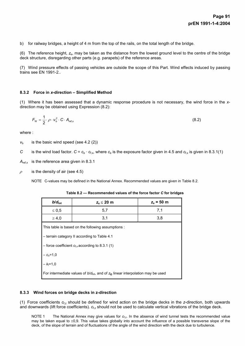
Page 91 prEN 1991-1-4:2004
b) for railway bridges, a height of 4 m from the top of the rails, on the total length of the bridge.
(6) The reference height, ze, may be taken as the distance from the lowest ground level to the centre of the bridge deck structure, disregarding other parts (e.g. parapets) of the reference areas.
(7) Wind pressure effects of passing vehicles are outside the scope of this Part. Wind effects induced by passing trains see EN 1991-2..
8.3.2 Force in x-direction – Simplified Method
(1) Where it has been assessed that a dynamic response procedure is not necessary, the wind force in the x-direction may be obtained using Expression (8.2):
xref,2bW 2
1 ACvF ⋅⋅⋅⋅= ρ (8.2)
where :
vb is the basic wind speed (see 4.2 (2))
C is the wind load factor. C = ce · cf,x, where ce is the exposure factor given in 4.5 and cf,x is given in 8.3.1(1)
Aref,x is the reference area given in 8.3.1
ρ is the density of air (see 4.5)
NOTE C-values may be defined in the National Annex. Recommended values are given in Table 8.2.
Table 8.2 — Recommended values of the force factor C for bridges
b/dtot ze ≤ 20 m ze = 50 m
≤ 0,5 5,7 7,1
≥ 4,0 3,1 3,8
This table is based on the following assumptions :
– terrain category II according to Table 4.1
– force coefficient cf,x according to 8.3.1 (1)
– co=1,0
– kI=1,0
For intermediate values of b/dtot, and of ze linear interpolation may be used
8.3.3 Wind forces on bridge decks in z-direction
(1) Force coefficients cf,z should be defined for wind action on the bridge decks in the z-direction, both upwards and downwards (lift force coefficients). cf,z should not be used to calculate vertical vibrations of the bridge deck.
NOTE 1 The National Annex may give values for cf,z. In the absence of wind tunnel tests the recommended value may be taken equal to ±0,9. This value takes globally into account the influence of a possible transverse slope of the deck, of the slope of terrain and of fluctuations of the angle of the wind direction with the deck due to turbulence.
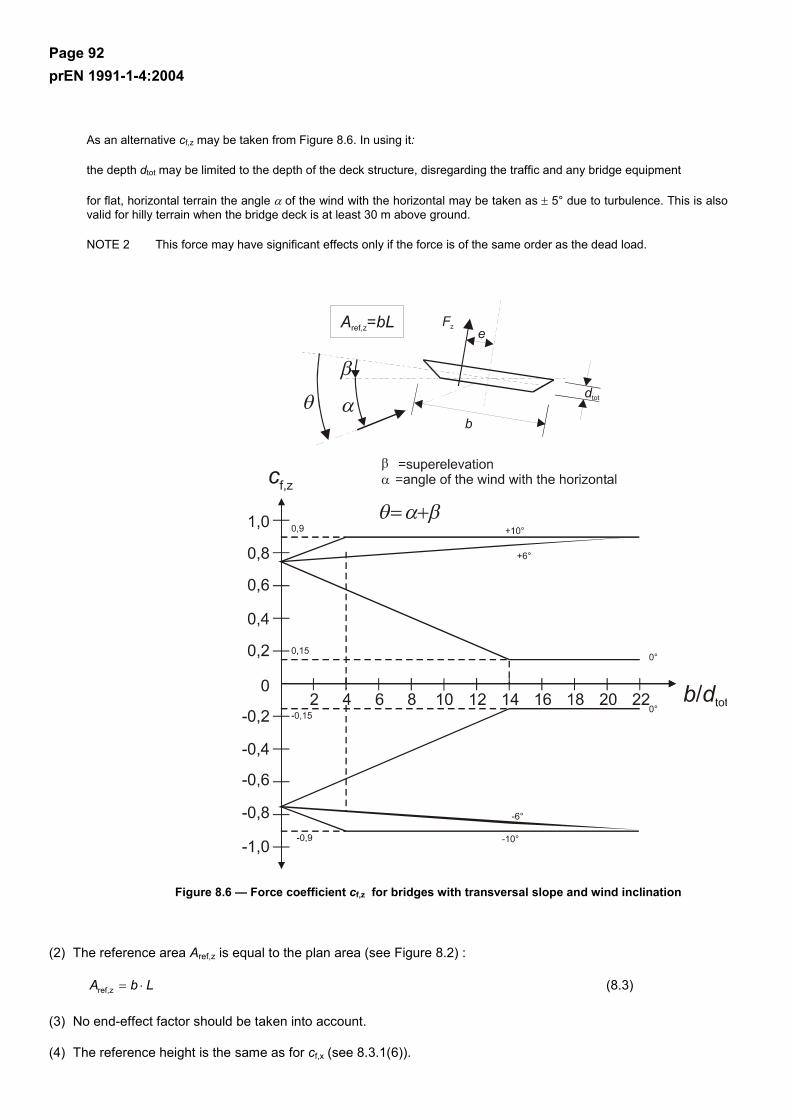
Page 92 prEN 1991-1-4:2004
As an alternative cf,z may be taken from Figure 8.6. In using it:
the depth dtot may be limited to the depth of the deck structure, disregarding the traffic and any bridge equipment
for flat, horizontal terrain the angle α of the wind with the horizontal may be taken as ± 5° due to turbulence. This is also valid for hilly terrain when the bridge deck is at least 30 m above ground.
NOTE 2 This force may have significant effects only if the force is of the same order as the dead load.
Figure 8.6 — Force coefficient cf,z for bridges with transversal slope and wind inclination
(2) The reference area Aref,z is equal to the plan area (see Figure 8.2) :
LbA ⋅=zref, (8.3)
(3) No end-effect factor should be taken into account.
(4) The reference height is the same as for cf,x (see 8.3.1(6)).

Page 93 prEN 1991-1-4:2004
(5) If not otherwise specified the eccentricity of the force in the x-direction may be set to e = b/4.
8.3.4 Wind forces on bridge decks in y-direction
(1) If necessary, the longitudinal wind forces in y-direction should be taken into account.
NOTE The National Annex may give the values. The recommended values are:
– for plated bridges, 25 % of the wind forces in x-direction,
– for truss bridges, 50 % of the wind forces in x-direction.
8.4 Bridge piers
8.4.1 Wind directions and design situations
(1) The wind actions on bridge decks and their supporting piers should be calculated by identifying the most unfavourable direction of the wind on the whole structure for the effect under consideration.
(2) Separate calculations of wind actions should be made for transient design situations during construction phases when no horizontal transmission or redistribution of wind actions by the deck is possible. If during such phases a pier may bear cantilevering deck parts or scaffoldings, a possible asymmetry of wind actions on such elements should be taken into account.
NOTE Execution transient situations are usually more critical for piers and for some types of decks subject to particular execution methods than the persistent ones. For characteristic values during transient design situations see EN 1991-1-6. For scaffoldings, see 7.11.
8.4.2 Wind effects on piers
(1) Wind effects on piers should be calculated by using the general format defined in this Eurocode. For overall loads the provisions of Clauses 7.6, 7.8 or 7.9.2 should be used.
NOTE 1 Simplified rules may be given in the National Annex.
NOTE 2 The National Annex may give procedures for the treatment of asymmetric loading. The recommended procedure is to completely remove the design wind load from those parts of the structure where its action will produce a beneficial effect (see 7.1.2 (1)).
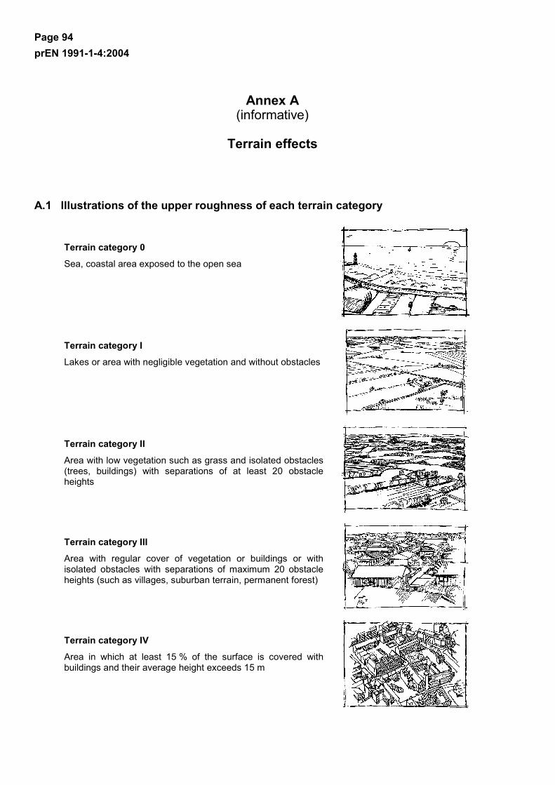
Page 94 prEN 1991-1-4:2004
Annex A (informative)
Terrain effects
A.1 Illustrations of the upper roughness of each terrain category
Terrain category 0
Sea, coastal area exposed to the open sea
Terrain category I
Lakes or area with negligible vegetation and without obstacles
Terrain category II
Area with low vegetation such as grass and isolated obstacles (trees, buildings) with separations of at least 20 obstacle heights
Terrain category III
Area with regular cover of vegetation or buildings or with isolated obstacles with separations of maximum 20 obstacle heights (such as villages, suburban terrain, permanent forest)
Terrain category IV
Area in which at least 15 % of the surface is covered with buildings and their average height exceeds 15 m

Page 95 prEN 1991-1-4:2004
A.2 Transition between roughness categories 0, I, II, III and IV
(1) The transition between different roughness categories has to be considered when calculating qp and cscd .
NOTE The procedure to be used may be given in the National Annex. Two recommended procedures, Procedure 1 and Procedure 2, are given below.
Procedure 1
If the structure is situated near a change of terrain roughness at a distance:
– less than 2 km from the smoother category 0 – less than 1 km from the smoother categories I to III the smoother terrain category in the upwind direction should be used
Small areas (less than 10 % of the area under consideration) with deviating roughness can be ignored.
Procedure 2
a) Determine the roughness categories for the upstream terrain in the angular sectors to be considered.
b) For every angular sector, determine the distance x from the building to the upstream roughness changes
c) If the distance x from the building to a terrain with lower roughness length is smaller than the values given in Table A.1, then the lower value for the roughness length should be used for the angular sector considered. If this distance x is larger than the value in Table A.2, the higher value for the roughness length should be used.
Small areas (less than 10 % of the area under consideration) with deviating roughness can be ignored.
Where no distance x is given in Table A.1 or for heights exceeding 50 m, the smaller roughness length should be used.
For intermediate values of height z, linear interpolation may be used.
A building in a certain terrain category may be calculated in a lower terrain category if it is situated within the distance limits defined in Table A.1

Page 96 prEN 1991-1-4:2004
Table A.1 — Distance x
Height z I to II I to III
5 m 0,50 km 5,00 km
7 m 1,00 km 10,00 km
10 m 2,00 km 20,00 km
15 m 5,00 km
20 m 12,00 km
30 m 20,00 km
50 m 50,00 km
Height z II to III II to IV
5 m 0,30 km 2,00 km
7 m 0,50 km 3,50 km
10 m 1,00 km 7,00 km
15 m 3,00 km 20,00 km
20 m 7,00 km
30 m 10,00 km
50 m 30,00 km
Height z III to IV
5 m 0,20 km
7 m 0,35 km
10 m 0,70 km
15 m 2,00 km
20 m 4,50 km
30 m 7,00 km
50 m 20,00 km
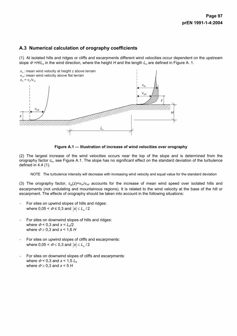
Page 97 prEN 1991-1-4:2004
A.3 Numerical calculation of orography coefficients
(1) At isolated hills and ridges or cliffs and escarpments different wind velocities occur dependent on the upstream slope Φ =H/Lu in the wind direction, where the height H and the length Lu are defined in Figure A. 1.
Figure A.1 — Illustration of increase of wind velocities over orography
(2) The largest increase of the wind velocities occurs near the top of the slope and is determined from the orography factor co, see Figure A.1. The slope has no significant effect on the standard deviation of the turbulence defined in 4.4 (1).
NOTE The turbulence intensity will decrease with increasing wind velocity and equal value for the standard deviation
(3) The orography factor, co(z)=vm/vmf accounts for the increase of mean wind speed over isolated hills and escarpments (not undulating and mountainous regions). It is related to the wind velocity at the base of the hill or escarpment. The effects of orography should be taken into account in the following situations:
– For sites on upwind slopes of hills and ridges: where 0,05 < Φ ≤ 0,3 and 2/uLx ≤
– For sites on downwind slopes of hills and ridges: where Φ < 0,3 and x < Ld/2 where Φ ≥ 0,3 and x < 1,6 H
– For sites on upwind slopes of cliffs and escarpments: where 0,05 < Φ ≤ 0,3 and 2/uLx ≤
– For sites on downwind slopes of cliffs and escarpments: where Φ < 0,3 and x < 1,5 Le where Φ ≥ 0,3 and x < 5 H
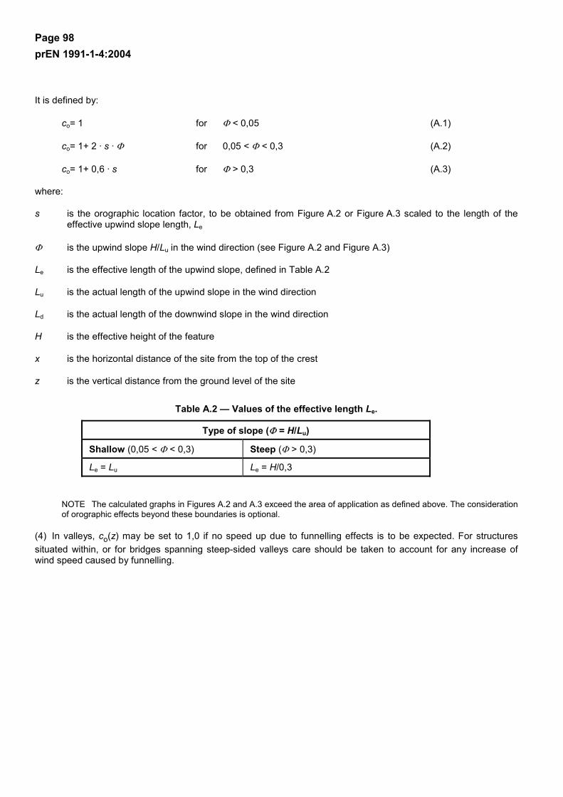
Page 98 prEN 1991-1-4:2004
It is defined by:
co= 1 for Φ < 0,05 (A.1)
co= 1+ 2 · s · Φ for 0,05 < Φ < 0,3 (A.2)
co= 1+ 0,6 · s for Φ > 0,3 (A.3)
where:
s is the orographic location factor, to be obtained from Figure A.2 or Figure A.3 scaled to the length of the effective upwind slope length, Le
Φ is the upwind slope H/Lu in the wind direction (see Figure A.2 and Figure A.3)
Le is the effective length of the upwind slope, defined in Table A.2
Lu is the actual length of the upwind slope in the wind direction
Ld is the actual length of the downwind slope in the wind direction
H is the effective height of the feature
x is the horizontal distance of the site from the top of the crest
z is the vertical distance from the ground level of the site
Table A.2 — Values of the effective length Le.
Type of slope (Φ = H/Lu)
Shallow (0,05 < Φ < 0,3) Steep (Φ > 0,3)
Le = Lu Le = H/0,3
NOTE The calculated graphs in Figures A.2 and A.3 exceed the area of application as defined above. The consideration of orographic effects beyond these boundaries is optional.
(4) In valleys, co(z) may be set to 1,0 if no speed up due to funnelling effects is to be expected. For structures situated within, or for bridges spanning steep-sided valleys care should be taken to account for any increase of wind speed caused by funnelling.
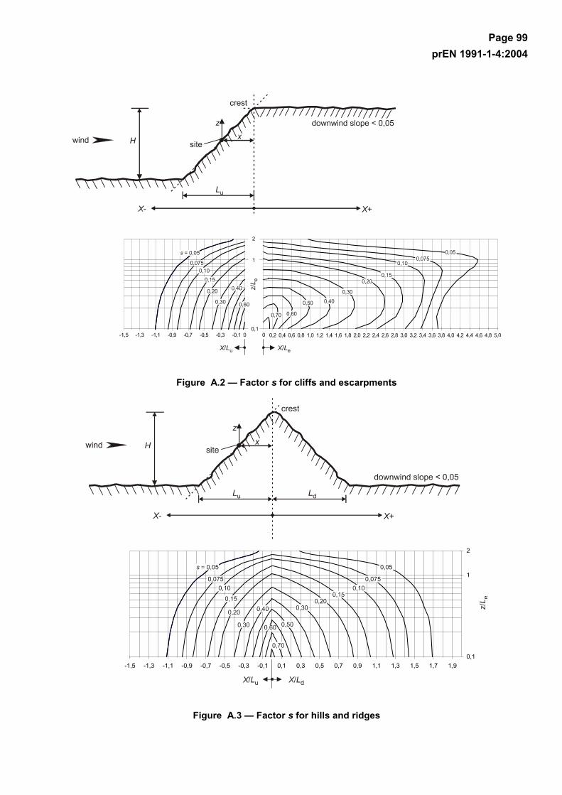
Page 99 prEN 1991-1-4:2004
Figure A.2 — Factor s for cliffs and escarpments
Figure A.3 — Factor s for hills and ridges
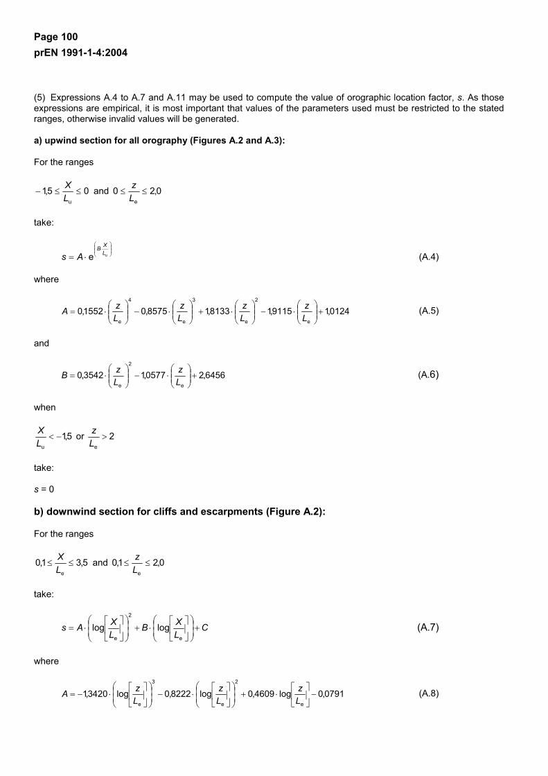
Page 100 prEN 1991-1-4:2004
(5) Expressions A.4 to A.7 and A.11 may be used to compute the value of orographic location factor, s. As those expressions are empirical, it is most important that values of the parameters used must be restricted to the stated ranges, otherwise invalid values will be generated.
a) upwind section for all orography (Figures A.2 and A.3):
For the ranges
05,1u
≤≤−LX and 0,20
e
≤≤Lz
take:
⋅
⋅= ue LXB
As (A.4)
where
0124,19115,18133,18575,01552,0e
2
e
3
e
4
e
+
⋅−
⋅+
⋅−
⋅=
Lz
Lz
Lz
LzA (A.5)
and
6456,20577,13542,0e
2
e
+
⋅−
⋅=
Lz
LzB (A.6)
when
5,1u
−<LX or 2
e
>Lz
take:
s = 0
b) downwind section for cliffs and escarpments (Figure A.2):
For the ranges
5,31,0e
≤≤LX and 0,21,0
e
≤≤Lz
take:
CLXB
LXAs +
⋅+
⋅=
e
2
e
loglog (A.7)
where
0791,0log4609,0log8222,0log3420,1e
2
e
3
e
−
⋅+
⋅−
⋅−=
Lz
Lz
LzA (A.8)

Page 101 prEN 1991-1-4:2004
1156,0log5343,0log8910,0log0196,1e
2
e
3
e
−
⋅+
⋅−
⋅−=
Lz
Lz
LzB (A.9)
and
1606,0log5738,0log4236,0log8030,0e
2
e
3
e
+
⋅−
⋅+
⋅=
Lz
Lz
LzC (A.10)
For the range
1,00e
≤≤LX ,
interpolate between values for
0e
=LX (s = A in Expression A.5) and 1,0
e
=LX .
when: 1,0e
<Lz use the values for 1,0
e
=Lz .
when: 5,3d
>Lz or 0,2
e
>Lz take the value s = 0
c) downwind section for hills and ridges (Figure A.3):
For the ranges
0,20d
≤≤LX and 0,20
e
≤≤Lz
take:
⋅
⋅= dLXB
eAs (A.11)
where:
0124,19115,18133,18575,01552,0e
2
e
3
e
4
e
+
⋅−
⋅+
⋅−
⋅=
Lz
Lz
Lz
LzA (A.12)
and
7637,10212,13056,0e
2
e
−
⋅+
⋅−=
Lz
LzB (A.13)
when
0,2d
>LX or 0,2
e
>Lz
Page 102 prEN 1991-1-4:2004
take:
s = 0
NOTE Expressions A.5 and A.12 are identical.
A.4 Neighbouring structures
(1) If a building is more than twice as high as the average height have of the neighbouring structures then, as a first approximation, the design of any of those nearby structures may be based on the peak velocity pressure at height zn (ze = zn) above ground (Expression A.14), see Figure A.4.
rx ≤ : rz ⋅=21
n
rxr ⋅<< 2 :
−⋅
⋅−−= )()
21(
21 low
n rxrhrz (A.14)
rx ⋅≥ 2 : lown hz =
in which the radius r is:
r = hhigh if hhigh ≤ 2 ⋅ dlarge
r = 2 ⋅ dlarge if hhigh > 2 ⋅ dlarge
The structural height hlow, the radius r, the distance x and the dimensions dsmall and dlarge are illustrated in Figure A.4 Increased wind velocities can be disregarded when hlow is more than half the height hhigh of the high building, i.e. zn = hlow.
Figure A.4 — Influence of a high rise building, on two different nearby structures (1 and 2)
Page 103 prEN 1991-1-4:2004
A.5 Displacement height
(1) For buildings in terrain category IV, closely spaced buildings and other obstructions causes the wind to behave as if the ground level was raised to a displacement height, hdis. hdis may be determined by Expression (A.15), see Figure A.5. The profile of peak velocity pressure over height (see Figure 4.2) may be lifted by a height hdis.
Figure A.5 — Obstruction height and upwind spacing
x ≤ 2 ⋅ have hdis is the lesser of 0,8 ⋅ have or 0,6 ⋅ h
2 ⋅ have < x < 6 ⋅ have hdis is the lesser of 1,2 ⋅ have – 0,2 ⋅ x or 0,6 ⋅ h (A.15)
x ≥ 6 ⋅ have hdis = 0
In the absence of more accurate information the obstruction height may be taken as have = 15 m for terrain category IV.
These rules are direction dependent, the values of have and x should be established for each 30° sector as described in 4.3.2.
Page 104 prEN 1991-1-4:2004
Annex B (informative)
Procedure 1 for determining the structural factor cscd
B.1 Wind turbulence
(1) The turbulent length scale L(z) represents the average gust size for natural winds. For heights z below 200 m the turbulent length scale may be calculated using Expression (B.1):
minmin
min
for)()(
fort
t)(
zzzLzL
zzzzLzL
<=
≥
⋅=
α
(B.1)
with a reference height of zt = 200 m, a reference length scale of Lt = 300 m, and with α = 0,67 + 0,05 ln(z0), where the roughness length z0 is in m. The minimum height zmin is given in Table 4.1.
(2) The wind distribution over frequencies is expressed by the non-dimensional power spectral density function SL(z,n), which should be determined using Expression (B.2):
35
L
L2v
vL 2101
86/(z,n))f,(
(z,n)f,(z,n)Sn(z,n)S
⋅+
⋅=
⋅=
σ (B.2)
where Sv(z,n) is the one-sided variance spectrum, and
)()(),(
mL zv
zLnnzf ⋅= is a non-dimensional frequency determined by the frequency n = n1,x, the natural
frequency of the structure in Hz, by the mean velocity vm(z) and the turbulence length scale L(z) defined in (B. 1). The power spectral density function is illustrated in Figure B.1.
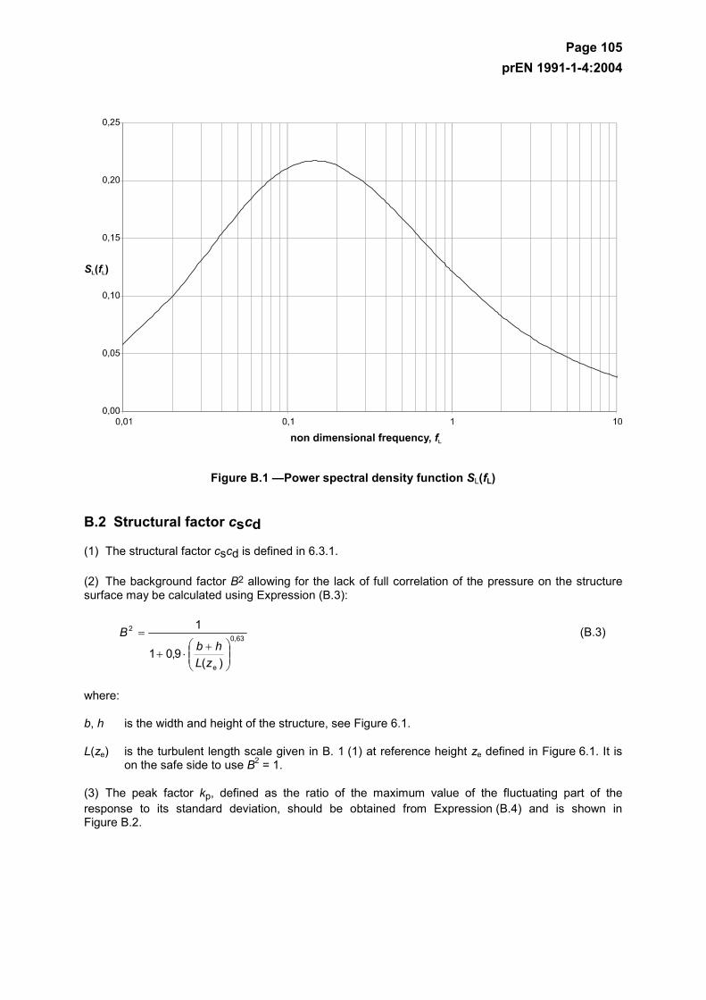
Page 105 prEN 1991-1-4:2004
Figure B.1 —Power spectral density function SL(fL)
B.2 Structural factor cscd
(1) The structural factor cscd is defined in 6.3.1.
(2) The background factor B2 allowing for the lack of full correlation of the pressure on the structure surface may be calculated using Expression (B.3):
63,0
e
2
)(9,01
1
+⋅+
=
zLhb
B (B.3)
where:
b, h is the width and height of the structure, see Figure 6.1.
L(ze) is the turbulent length scale given in B. 1 (1) at reference height ze defined in Figure 6.1. It is on the safe side to use B2 = 1.
(3) The peak factor kp, defined as the ratio of the maximum value of the fluctuating part of the response to its standard deviation, should be obtained from Expression (B.4) and is shown in Figure B.2.
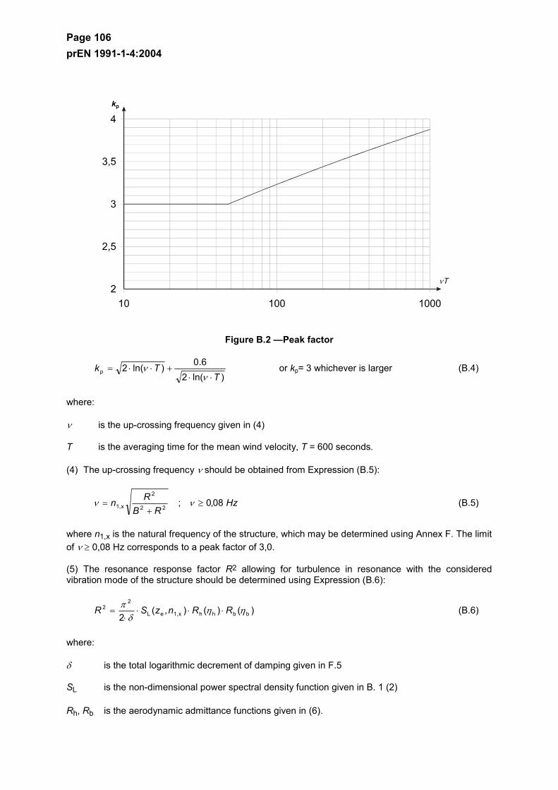
Page 106 prEN 1991-1-4:2004
Figure B.2 —Peak factor
)ln(2
6.0)ln(2pT
Tk⋅⋅
+⋅⋅=ν
ν or kp= 3 whichever is larger (B.4)
where:
ν is the up-crossing frequency given in (4)
T is the averaging time for the mean wind velocity, T = 600 seconds.
(4) The up-crossing frequency ν should be obtained from Expression (B.5):
HzRB
Rn 08,0;22
2
x1, ≥+
= νν (B.5)
where n1,x is the natural frequency of the structure, which may be determined using Annex F. The limit of ν ≥ 0,08 Hz corresponds to a peak factor of 3,0.
(5) The resonance response factor R2 allowing for turbulence in resonance with the considered vibration mode of the structure should be determined using Expression (B.6):
)()(),(2 bbhhx1,eL
22 ηη
δπ RRnzSR ⋅⋅⋅⋅
= (B.6)
where:
δ is the total logarithmic decrement of damping given in F.5
SL is the non-dimensional power spectral density function given in B. 1 (2)
Rh, Rb is the aerodynamic admittance functions given in (6).
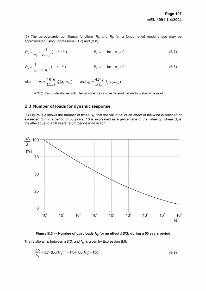
Page 107 prEN 1991-1-4:2004
(6) The aerodynamic admittance functions Rh and Rb for a fundamental mode shape may be approximated using Expressions (B.7) and (B.8):
)1(2
11h2
2hh
hη
ηη⋅−−
⋅−= eR ; 0for1 hh == ηR (B.7)
)1(2
11b2
2bb
bη
ηη⋅−−
⋅−= eR ; 0for1 bb == ηR (B.8)
with: ),()(
6,4x1,eL
eh nzf
zLh
⋅⋅
=η and ),()(
6,4x1,eL
eb nzf
zLb
⋅⋅
=η
NOTE For mode shapes with internal node points more detailed calculations should be used.
B.3 Number of loads for dynamic response
(1) Figure B.3 shows the number of times Ng, that the value ∆S of an effect of the wind is reached or exceeded during a period of 50 years. ∆S is expressed as a percentage of the value Sk, where Sk is the effect due to a 50 years return period wind action.
Figure B.3 — Number of gust loads Ng for an effect ∆S/Sk during a 50 years period
The relationship between ∆S/Sk and Ng is given by Expression B.9.
100)log(4,17))(log(7,0∆g
2g
k
+⋅−⋅= NNS
S (B.9)
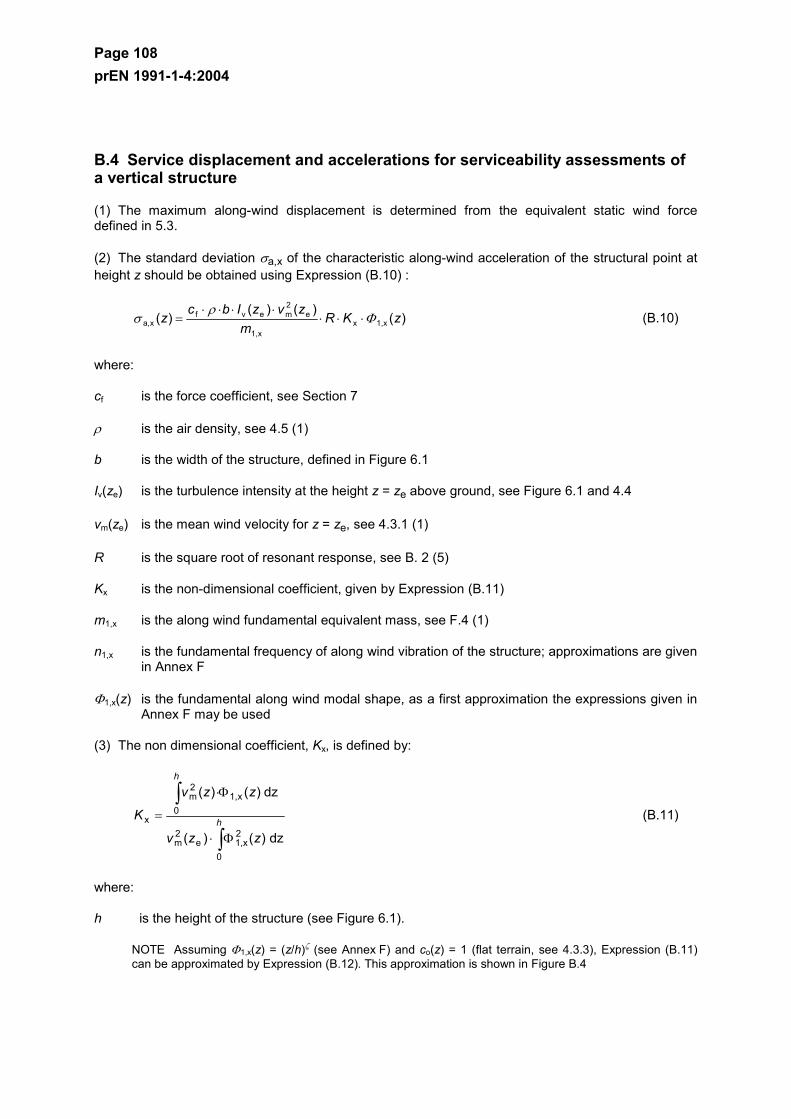
Page 108 prEN 1991-1-4:2004
B.4 Service displacement and accelerations for serviceability assessments of a vertical structure
(1) The maximum along-wind displacement is determined from the equivalent static wind force defined in 5.3.
(2) The standard deviation σa,x of the characteristic along-wind acceleration of the structural point at height z should be obtained using Expression (B.10) :
)()()(
)( x1,xx1,
e2mevf
xa, zKRm
zvzIbcz Φρ
σ ⋅⋅⋅⋅⋅⋅⋅
= (B.10)
where:
cf is the force coefficient, see Section 7
ρ is the air density, see 4.5 (1)
b is the width of the structure, defined in Figure 6.1
Iv(ze) is the turbulence intensity at the height z = ze above ground, see Figure 6.1 and 4.4
vm(ze) is the mean wind velocity for z = ze, see 4.3.1 (1)
R is the square root of resonant response, see B. 2 (5)
Kx is the non-dimensional coefficient, given by Expression (B.11)
m1,x is the along wind fundamental equivalent mass, see F.4 (1)
n1,x is the fundamental frequency of along wind vibration of the structure; approximations are given in Annex F
Φ1,x(z) is the fundamental along wind modal shape, as a first approximation the expressions given in Annex F may be used
(3) The non dimensional coefficient, Kx, is defined by:
dz)()(
dz)()(
0
2x1,e
2m
x1,0
2m
x
∫
∫
Φ⋅
Φ⋅
= h
h
zzv
zzv
K (B.11)
where:
h is the height of the structure (see Figure 6.1).
NOTE Assuming Φ1,x(z) = (z/h)ζ (see Annex F) and co(z) = 1 (flat terrain, see 4.3.3), Expression (B.11) can be approximated by Expression (B.12). This approximation is shown in Figure B.4
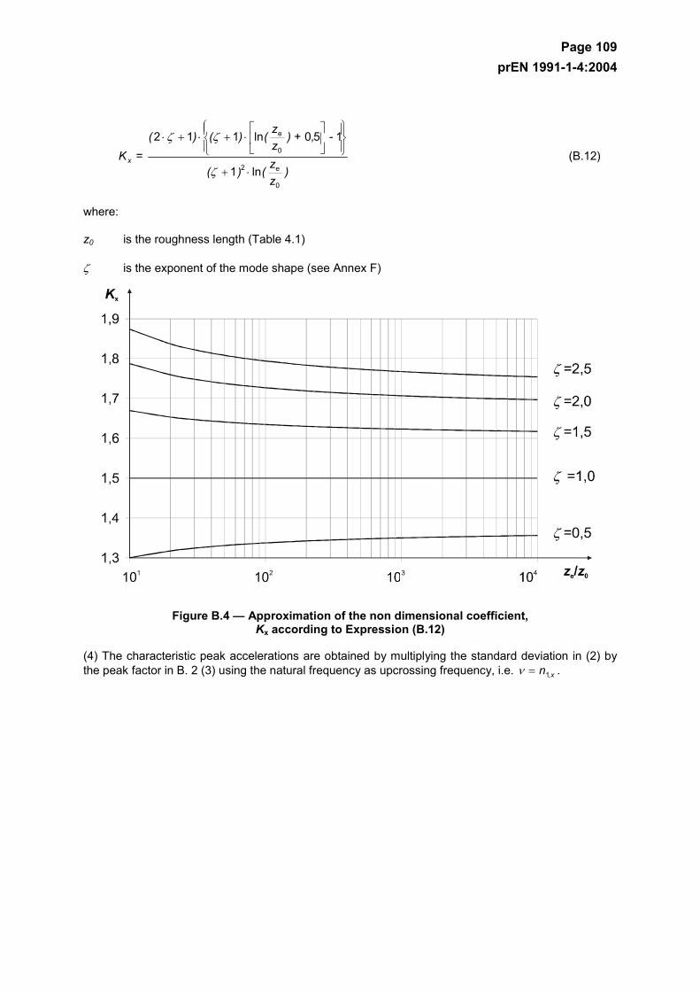
Page 109 prEN 1991-1-4:2004
)
zz()(
- ,) + zz()()(
= K x
0
e2
0
e
ln1
150ln112
⋅+
⋅+⋅+⋅
ζ
ζζ
(B.12)
where:
z0 is the roughness length (Table 4.1)
ζ is the exponent of the mode shape (see Annex F)
Figure B.4 — Approximation of the non dimensional coefficient, Kx according to Expression (B.12)
(4) The characteristic peak accelerations are obtained by multiplying the standard deviation in (2) by the peak factor in B. 2 (3) using the natural frequency as upcrossing frequency, i.e. xn ,1=ν .
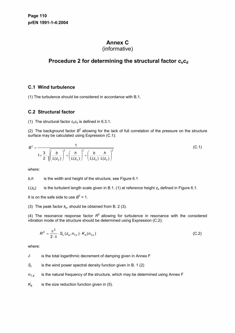
Page 110 prEN 1991-1-4:2004
Annex C (informative)
Procedure 2 for determining the structural factor cscd
C.1 Wind turbulence
(1) The turbulence should be considered in accordance with B.1.
C.2 Structural factor
(1) The structural factor cscd is defined in 6.3.1.
(2) The background factor B2 allowing for the lack of full correlation of the pressure on the structure surface may be calculated using Expression (C.1):
2
ee
2
e
2
e
2
)()()()(231
1
⋅+
+
⋅+
=
zLh
zLb
zLh
zLb
B (C.1)
where:
b,h is the width and height of the structure, see Figure 6.1
L(ze) is the turbulent length scale given in B.1. (1) at reference height ze defined in Figure 6.1.
It is on the safe side to use B2 = 1.
(3) The peak factor kp, should be obtained from B. 2 (3).
(4) The resonance response factor R2 allowing for turbulence in resonance with the considered vibration mode of the structure should be determined using Expression (C.2):
)(),(2 ,1s,1eL
22
xx nKnzSR ⋅⋅δ⋅
π= (C.2)
where:
δ is the total logarithmic decrement of damping given in Annex F
SL is the wind power spectral density function given in B. 1 (2)
n1,x is the natural frequency of the structure, which may be determined using Annex F
Ks is the size reduction function given in (5).
Page 111 prEN 1991-1-4:2004
(5) The size reduction function Ks may be approximated by Expression (C.3):
2
zzyy2
zz2
yy
s
2)()(1
1)(
⋅⋅⋅⋅+⋅+⋅+
=
φφπ
φφ GGGG
nK (C.3)
)( em
yy zv
nbc ⋅⋅=φ
)( em
zz zv
nhc ⋅⋅=φ
The constants Gy and Gz depend on the mode shape variation along the horizontal y-axis and vertical z-axis, respectively. The decay constants cy and cz are both equal to 11,5.
(6) The constant G introduced in (5) and the constant K used to calculate accelerations, are shown in Table C.1.
Table C.1 — G and K as a function of mode shape
Mode shape Uniform Linear Parabolic Sinusoidal
G: 1/2 3/8 5/18 4/π²
K: 1 3/2 5/3 4/π
NOTE 1 For buildings with a uniform horizontal mode shape variation and a linear vertical mode shape variation Φ(y,z) = z/h, Gy = 1/2, Gz = 3/8, Ky = 1 and Kz = 3/2.
NOTE 2 For chimneys with a uniform horizontal mode shape variation and a parabolic vertical mode shape variation Φ(y,z) = z2/h2, Gy = 1/2, Gz = 5/18, Ky = 1 and Kz = 5/3.
NOTE 3 For bridges with a sinusoidal horizontal mode shape variation Φ(y,z) = sin(π⋅y/b), Gy = 4/π2, Gz = 1/2, Ky = 4/π and Kz = 1.
C.3 Number of loads for dynamic response
(1) The number of loads should be obtained from B. 3.
C.4 Service displacement and accelerations for serviceability assessments
(1) The maximum along-wind displacement is the static displacement determined from the equivalent static wind force defined in 5.2.
(2) The standard deviation σa,x of the characteristic along-wind acceleration of the structural point with coordinates (y,z) is approximately given by Expression (C.4):
maxref
zye
2mevfxa,
),()()(),(
Φµ
Φρσ
⋅
⋅⋅⋅⋅⋅⋅⋅=
zyKKRzvzIczy (C.4)
where:
cf is the force coefficient, see Section 7

Page 112 prEN 1991-1-4:2004
ρ is the air density, see 4.5
Iv(ze) is the turbulence intensity at height ze above ground, see 4.4 (1)
vm(ze) is the characteristic mean wind velocity at height ze, above ground, see 4.3.1 (1)
R is the square root of the resonant response, see C.2 (4)
Ky,Kz is the constants given in C.2 (6)
µref is the reference mass per unit area, see F.5 (3)
Φ(y,z) is the mode shape
Φmax is the mode shape value at the point with maximum amplitude
(3) The characteristic peak accelerations are obtained by multiplying the standard deviation in (2) by the peak factor in B. 2 (3) using the natural frequency as upcrossing frequency, i.e. v = n1,x.
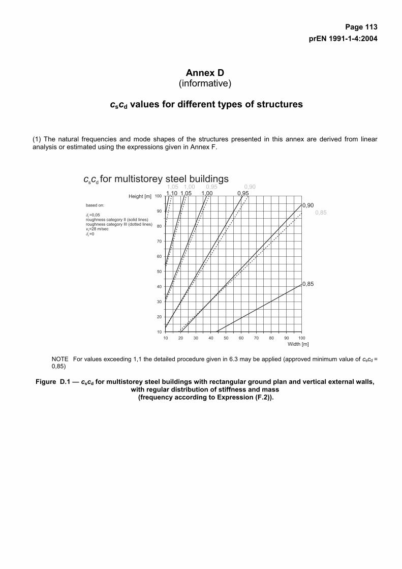
Page 113 prEN 1991-1-4:2004
Annex D (informative)
cscd values for different types of structures
(1) The natural frequencies and mode shapes of the structures presented in this annex are derived from linear analysis or estimated using the expressions given in Annex F.
NOTE For values exceeding 1,1 the detailed procedure given in 6.3 may be applied (approved minimum value of cscd = 0,85)
Figure D.1 — cscd for multistorey steel buildings with rectangular ground plan and vertical external walls, with regular distribution of stiffness and mass
(frequency according to Expression (F.2)).
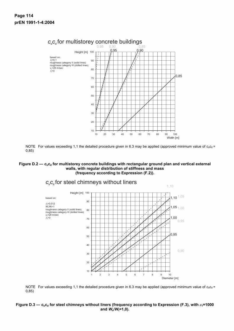
Page 114 prEN 1991-1-4:2004
NOTE For values exceeding 1,1 the detailed procedure given in 6.3 may be applied (approved minimum value of cscd = 0,85)
Figure D.2 — cscd for multistorey concrete buildings with rectangular ground plan and vertical external walls, with regular distribution of stiffness and mass
(frequency according to Expression (F.2)).
NOTE For values exceeding 1,1 the detailed procedure given in 6.3 may be applied (approved minimum value of cscd = 0,85)
Figure D.3 — cscd for steel chimneys without liners (frequency according to Expression (F.3), with ε1=1000 and Ws/Wt=1,0).
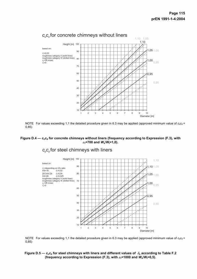
Page 115 prEN 1991-1-4:2004
NOTE For values exceeding 1,1 the detailed procedure given in 6.3 may be applied (approved minimum value of cscd = 0,85)
Figure D.4 — cscd for concrete chimneys without liners (frequency according to Expression (F.3), with ε1=700 and Ws/Wt=1,0).
NOTE For values exceeding 1,1 the detailed procedure given in 6.3 may be applied (approved minimum value of cscd = 0,85)
Figure D.5 — cscd for steel chimneys with liners and different values of δs according to Table F.2 (frequency according to Expression (F.3), with ε1=1000 and Ws/Wt=0,5).
Page 116 prEN 1991-1-4:2004
Annex E (informative)
Vortex shedding and aeroelastic instabilities
E.1 Vortex shedding
E.1.1 General
(1) Vortex-shedding occurs when vortices are shed alternately from opposite sides of the structure. This gives rise to a fluctuating load perpendicular to the wind direction. Structural vibrations may occur if the frequency of vortex–shedding is the same as a natural frequency of the structure. This condition occurs when the wind velocity is equal to the critical wind velocity defined in E.1.3.1. Typically, the critical wind velocity is a frequent wind velocity indicating that fatigue, and thereby the number of load cycles, may become relevant.
(2) The response induced by vortex shedding is composed of broad-banded response that occurs whether or not the structure is moving, and narrow-banded response originating from motion-induced wind load.
NOTE 1 Broad-banded response is normally most important for reinforced concrete structures and heavy steel structures.
NOTE 2 Narrow-banded response is normally most important for light steel structures.
E.1.2 Criteria for vortex shedding
(1) The effect of vortex shedding should be investigated when the ratio of the largest to the smallest crosswind dimension of the structure, both taken in the plane perpendicular to the wind, exceeds 6.
(2) The effect of vortex shedding need not be investigated when
micrit, 25,1 vv ⋅> (E.1)
where:
vcrit,i is the critical wind velocity for mode i, as defined in E.1.3.1
vm is the characteristic 10 minutes mean wind velocity specified in 4.3.1 (1) at the cross section where vortex shedding occurs (see Figure E.3).
Page 117 prEN 1991-1-4:2004
E.1.3 Basic parameters for vortex shedding
E.1.3.1 Critical wind velocity vcrit,i
(1) The critical wind velocity for bending vibration mode i is defined as the wind velocity at which the frequency of vortex shedding equals a natural frequency of the structure or a structural element and is given in Expression (E.2).
Stnb
= vyi,
icrit,⋅
(E.2)
where:
b is the reference width of the cross-section at which resonant vortex shedding occurs and where the modal deflection is maximum for the structure or structural part considered; for circular cylinders the reference width is the outer diameter
ni,y is the natural frequency of the considered flexural mode i of cross-wind vibration; approximations for n1,y are given in F.2
St Strouhal number as defined in E.1.3.2.
.
(2) The critical wind velocity for ovalling vibration mode i of cylindrical shells is defined as the wind velocity at which two times of the frequency of vortex shedding equals a natural frequency of the ovalling mode i of the cylindrical shell and is given in Expression (E.3).
Stnb
v⋅⋅
=2
i,0icrit, (E.3)
where:
b is the outer shell diameter
St is the Strouhal number as defined in E.1.3.2
ni,o is the natural frequency of the ovalling mode i of the shell
.
NOTE 1 For shells without stiffening rings n0 is given in F.2 (3)
NOTE 2 Procedures to calculate ovalling vibrations are not covered in Annex E.
E.1.3.2 Strouhal number St
The Strouhal number St for different cross-sections may be taken from Table E.1
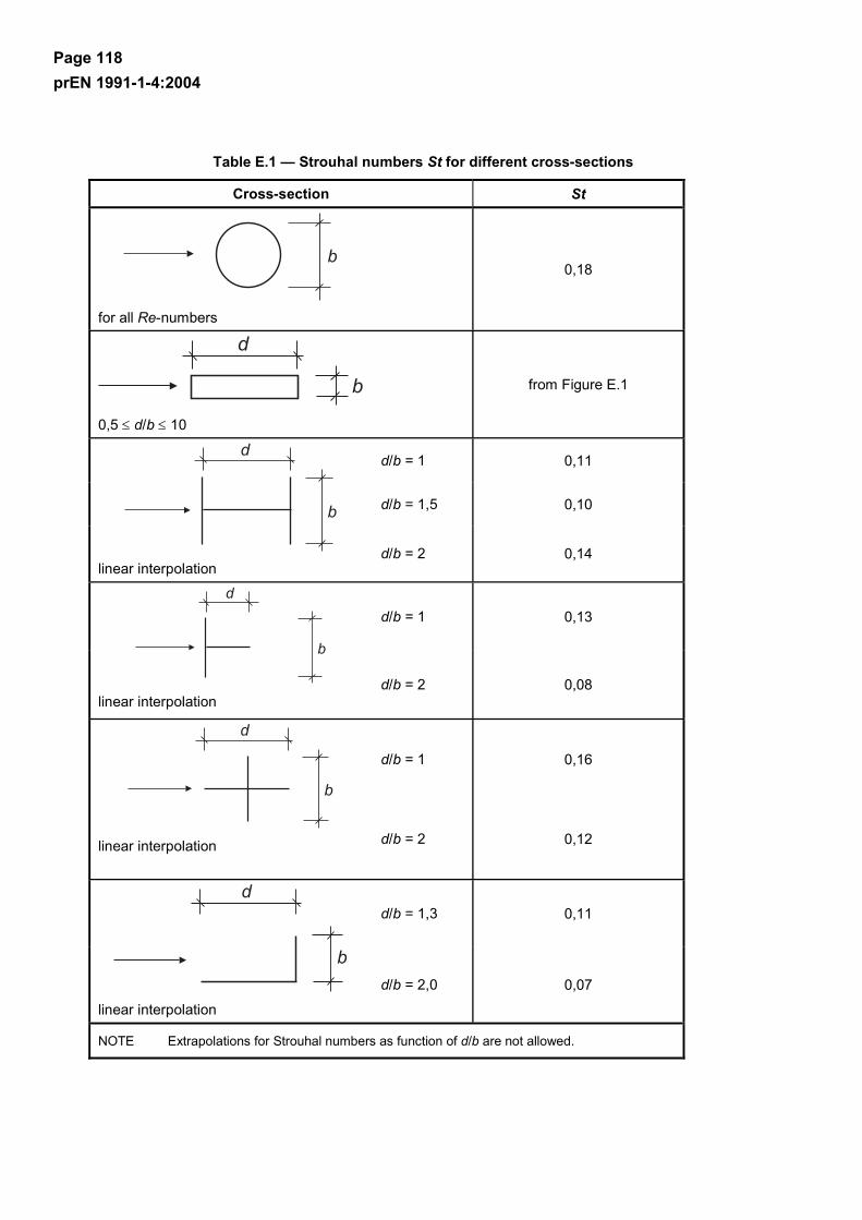
Page 118 prEN 1991-1-4:2004
Table E.1 — Strouhal numbers St for different cross-sections
Cross-section St
for all Re-numbers
0,18
0,5 ≤ d/b ≤ 10
from Figure E.1
d/b = 1 0,11
d/b = 1,5 0,10
linear interpolation
d/b = 2 0,14
d/b = 1 0,13
linear interpolation
d/b = 2 0,08
d/b = 1 0,16
linear interpolation d/b = 2 0,12
d/b = 1,3 0,11
linear interpolation
d/b = 2,0 0,07
NOTE Extrapolations for Strouhal numbers as function of d/b are not allowed.
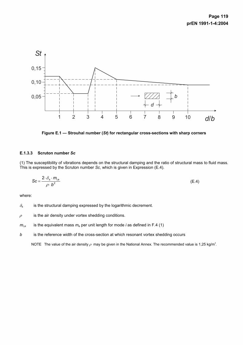
Page 119 prEN 1991-1-4:2004
Figure E.1 — Strouhal number (St) for rectangular cross-sections with sharp corners
E.1.3.3 Scruton number Sc
(1) The susceptibility of vibrations depends on the structural damping and the ratio of structural mass to fluid mass. This is expressed by the Scruton number Sc, which is given in Expression (E.4).
2ei,s2
bm
Sc⋅
⋅⋅=
ρδ
(E.4)
where:
δs is the structural damping expressed by the logarithmic decrement.
ρ is the air density under vortex shedding conditions.
mi,e is the equivalent mass me per unit length for mode i as defined in F.4 (1)
b is the reference width of the cross-section at which resonant vortex shedding occurs
NOTE The value of the air density ρ may be given in the National Annex. The recommended value is 1,25 kg/m3.
Page 120 prEN 1991-1-4:2004
E.1.3.4 Reynolds number Re
(1) The vortex shedding action on a circular cylinder depends on the Reynolds number Re at the critical wind velocity vcrit,i. The Reynolds number is given in Expression (E.5).
ν
icrit,icrit, )(
vbvRe
⋅= (E.5)
where:
b is the outer diameter of the circular cylinder
ν is the kinematic viscosity of the air ( 61015 −⋅≈ν m2/s)
vcrit,i is the critical wind velocity, see E.1.3.1
E.1.4 Vortex shedding action
(1) The effect of vibrations induced by vortex shedding should be calculated from the effect of the inertia force per unit length Fw(s), acting perpendicular to the wind direction at location s on the structure and given in Expression (E.6)
maxF,i,y2
i,yw )()2()()( ysnsmsF ⋅⋅⋅⋅⋅= Φπ (E.6)
where:
m(s) is the vibrating mass of the structure per unit length [kg/m]
ni,y is the natural frequency of the structure
Φ i,y(s) is the mode shape of the structure normalised to 1 at the point with the maximum displacement
yF,max is the maximum displacement over time of the point with Φi,y(s) equal to 1, see E.1.5
E.1.5 Calculation of the cross wind amplitude
E.1.5.1 General
(1) Two different approaches for calculating the vortex excited cross-wind amplitudes are given in E.1.5.2 and E.1.5.3.
NOTE 1 The choice of calculation approach or alternative calculation procedures may be specified in the National Annex.
NOTE 2 A direct comparison of the approaches proposed in E.1.5.2 and E.1.5.3 is not possible because some of the input parameters are chosen for different environmental conditions. The National Annex may define the range of application for each of the approaches proposed.
NOTE 3 Mixing of the approaches E.1.5.2 and E.1.5.3 is not allowed, except if it is specifically stated in the text.
(2) The approach given in E.1.5.2 can be used for various kind of structures and mode shapes. It includes turbulence and roughness effects and it may be used for normal climatic conditions.
(3) The approach given in E.1.5.3 may be used to calculate the response for vibrations in the first mode of cantilevered structures with a regular distribution of cross wind dimensions along the main axis of the structure. Typically structures covered are chimneys or masts. It cannot be applied for grouped or in-line arrangements and for coupled cylinders. This approach allows for the consideration of different turbulence intensities, which may differ
Page 121 prEN 1991-1-4:2004
due to meteorological conditions. For regions where it is likely that it may become very cold and stratified flow conditions may occur (e.g. in coastal areas in Northern Europe), approach E.1.5.3 may be used.
NOTE The National Annex may give the regions where very cold and stratified flow conditions may occur. For these regions the approach 2 in E.1.5.3 is more appropriate, and the National Annex may define appropriate input parameters (like Ka or turbulence intensity) which should be used in this approach.
E.1.5.2 Approach 1 for the calculation of the cross wind amplitudes
E.1.5.2.1 Calculation of displacements
The largest displacement yF,max can be calculated using Expression (E.7).
latW2maxF, 11 cKK
ScStby
⋅⋅⋅⋅= (E.7)
where:
St is the Strouhal number given in Table E.1
Sc is the Scruton number given in E.1.3.3
KW is the effective correlation length factor given in E.1.5.2.4
K is the mode shape factor given in E.1.5.2.5
clat is the lateral force coefficient given in Table E.2
NOTE The aeroelastic forces are taken into account by the effective correlation length factor KW.
E.1.5.2.2 Lateral force coefficient clat
(1) The basic value, clat,0, of the lateral force coefficient is given in Table E.2.
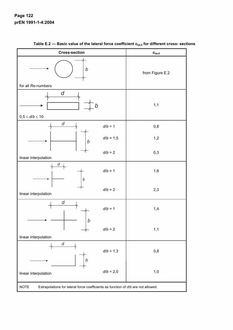
Page 122 prEN 1991-1-4:2004
Table E.2 — Basic value of the lateral force coefficient clat,0 for different cross- sections
Cross-section clat,0
for all Re-numbers
from Figure E.2
0,5 ≤ d/b ≤ 10
1,1
d/b = 1 0,8
d/b = 1,5 1,2
linear interpolation
d/b = 2 0,3
d/b = 1 1,6
linear interpolation
d/b = 2 2,3
d/b = 1 1,4
linear interpolation
d/b = 2 1,1
d/b = 1,3 0,8
linear interpolation d/b = 2,0 1,0
NOTE Extrapolations for lateral force coefficients as function of d/b are not allowed.
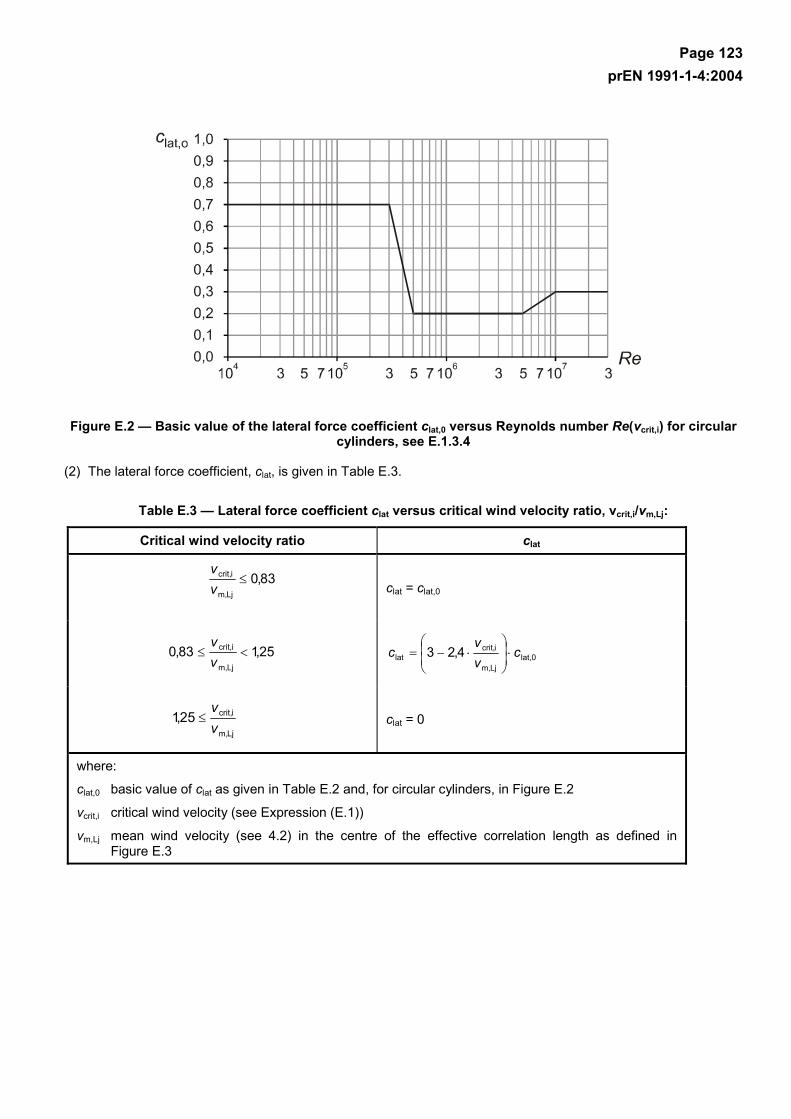
Page 123 prEN 1991-1-4:2004
Figure E.2 — Basic value of the lateral force coefficient clat,0 versus Reynolds number Re(vcrit,i) for circular cylinders, see E.1.3.4
(2) The lateral force coefficient, clat, is given in Table E.3.
Table E.3 — Lateral force coefficient clat versus critical wind velocity ratio, vcrit,i/vm,Lj:
Critical wind velocity ratio clat
83,0Ljm,
icrit, ≤vv
clat = clat,0
25,183,0Ljm,
icrit, <≤vv
lat,0Ljm,
icrit,lat 4,23 c
vv
c ⋅
⋅−=
Ljm,
icrit,25,1vv
≤ clat = 0
where:
clat,0 basic value of clat as given in Table E.2 and, for circular cylinders, in Figure E.2
vcrit,i critical wind velocity (see Expression (E.1))
vm,Lj mean wind velocity (see 4.2) in the centre of the effective correlation length as defined in Figure E.3

Page 124 prEN 1991-1-4:2004
E.1.5.2.3 Correlation length L
(1) The correlation length Lj, should be positioned in the range of antinodes. Examples are given in Figure E.3. For guyed masts and continuous multispan bridges special advice is necessary.
NOTE If more than one correlation length is shown, it is safe to use them simultaneously, and the highest value of clat should be used.
Figure E.3 — Examples for application of the correlation length Lj ( j = 1, 2, 3)
Table E.4 — Effective correlation length Lj as a function of vibration amplitude yF(sj)
yF(sj)/b Lj / b
< 0,1 6
0,1 to 0,6 b
)(sy +, jF1284 ⋅
> 0,6 12

Page 125 prEN 1991-1-4:2004
E.1.5.2.4 Effective correlation length factor KW
(1) The effective correlation length factor, KW, is given in Expression (E.8).
60ds
ds
,1
,1
W
j
j ,(s)| |
(s)| |
=K
yi
m
j=
yiL
n
j=≤
∫∑
∫∑
Φ
Φ
(E.8)
where:
Φi,y is the mode shape i (see F.3).
Lj is the correlation length
j is the length of the structure between two nodes (see Figure E.3); for cantilevered structures it is equal to the height of the structure
n is the number of regions where vortex excitation occurs at the same time (see Figure E.3)
m is the number of antinodes of the vibrating structure in the considered mode shape Φi,y
s is the coordinate defined in Table E.5.
(2) For some simple structures vibrating in the fundamental cross-wind mode and with the exciting force indicated in Table E.5 the effective correlation length factor KW can be approximated by the expressions given in Table E.5.
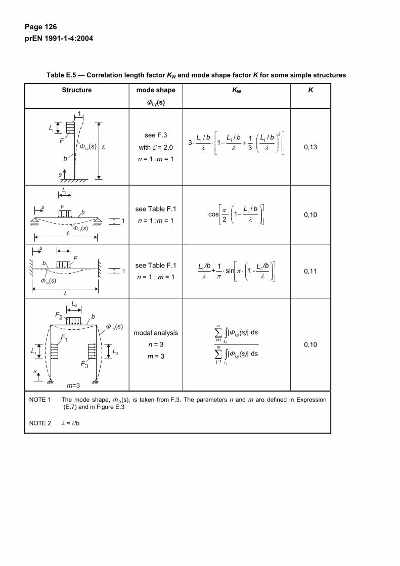
Page 126 prEN 1991-1-4:2004
Table E.5 — Correlation length factor KW and mode shape factor K for some simple structures
Structure mode shape
Φi,y(s)
KW K
see F.3
with ζ = 2,0
n = 1 ;m = 1
⋅+−⋅⋅
2jjj /
31/
1/
3λλλ
bLbLbL
0,13
see Table F.1
n = 1 ;m = 1
−⋅
λπ bL /
12
cos j 0,10
see Table F.1
n = 1 ; m = 1
⋅⋅
λπ
πλ/bL -+
/bL jj 1sin1 0,11
modal analysis
n = 3
m = 3 ds
ds
yi,1j
yi,1i
j
j
(s)| |
(s)| |
m
=
L
n
=
Φ
Φ
∫∑
∫∑ 0,10
NOTE 1 The mode shape, Φi,y(s), is taken from F.3. The parameters n and m are defined in Expression (E.7) and in Figure E.3
NOTE 2 λ = /b
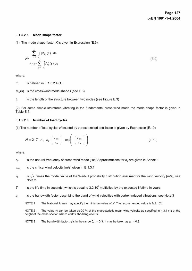
Page 127 prEN 1991-1-4:2004
E.1.5.2.5 Mode shape factor
(1) The mode shape factor K is given in Expression (E.9).
s
| s |
K= m
m
∫∑
∫∑
=
=
⋅⋅j
j
ds)(4
ds)(
2yi,
1j
yi,1j
Φπ
Φ
(E.9)
where:
m is defined in E.1.5.2.4 (1)
Φi,y(s) is the cross-wind mode shape i (see F.3)
j is the length of the structure between two nodes (see Figure E.3)
(2) For some simple structures vibrating in the fundamental cross-wind mode the mode shape factor is given in Table E.5.
E.1.5.2.6 Number of load cycles
(1) The number of load cycles N caused by vortex excited oscillation is given by Expression (E.10).
−⋅
⋅⋅⋅⋅=
2
0
crit2
0
crit0y exp2
vv
vvεnTN (E.10)
where:
ny is the natural frequency of cross-wind mode [Hz]. Approximations for ny are given in Annex F
vcrit is the critical wind velocity [m/s] given in E.1.3.1
v0 is 2 times the modal value of the Weibull probability distribution assumed for the wind velocity [m/s], see Note 2
T is the life time in seconds, which is equal to 3,2 107 multiplied by the expected lifetime in years
ε0 is the bandwidth factor describing the band of wind velocities with vortex-induced vibrations, see Note 3
NOTE 1 The National Annex may specify the minimum value of N. The recommended value is N ≥ 104.
NOTE 2 The value v0 can be taken as 20 % of the characteristic mean wind velocity as specified in 4.3.1 (1) at the height of the cross section where vortex shedding occurs.
NOTE 3 The bandwidth factor ε0 is in the range 0,1 – 0,3. It may be taken as ε0 = 0,3.
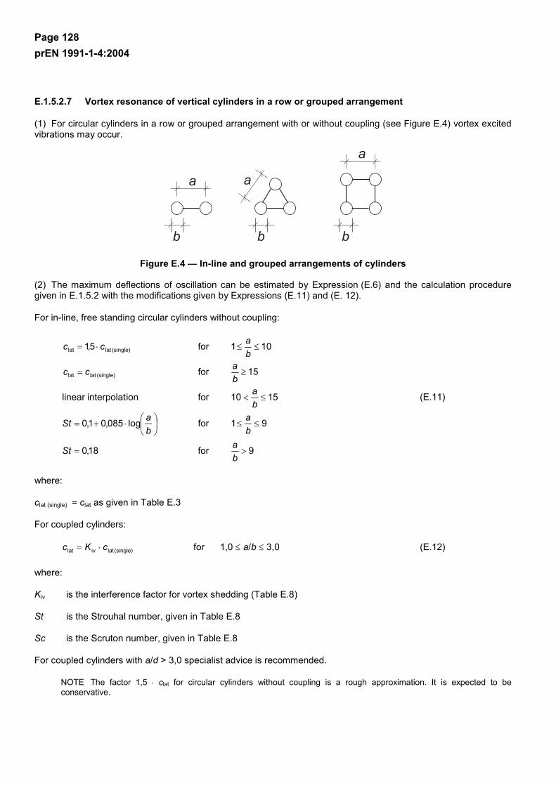
Page 128 prEN 1991-1-4:2004
E.1.5.2.7 Vortex resonance of vertical cylinders in a row or grouped arrangement
(1) For circular cylinders in a row or grouped arrangement with or without coupling (see Figure E.4) vortex excited vibrations may occur.
Figure E.4 — In-line and grouped arrangements of cylinders
(2) The maximum deflections of oscillation can be estimated by Expression (E.6) and the calculation procedure given in E.1.5.2 with the modifications given by Expressions (E.11) and (E. 12).
For in-line, free standing circular cylinders without coupling:
9for18,0
91forlog085,01,0
1510forioninterpolat linear
15for
101for5,1
(single)latlat
(single)latlat
>=
≤≤
⋅+=
≤<
≥=
≤≤⋅=
baSt
ba
baSt
ba
bacc
bacc
(E.11)
where:
clat (single) = clat as given in Table E.3
For coupled cylinders:
(single)lativlat cKc ⋅= for 1,0 ≤ a/b ≤ 3,0 (E.12)
where:
Kiv is the interference factor for vortex shedding (Table E.8)
St is the Strouhal number, given in Table E.8
Sc is the Scruton number, given in Table E.8
For coupled cylinders with a/d > 3,0 specialist advice is recommended.
NOTE The factor 1,5 ⋅ clat for circular cylinders without coupling is a rough approximation. It is expected to be conservative.
Page 129 prEN 1991-1-4:2004
E.1.5.3 Approach 2, for the calculation of the cross wind amplitudes
(1) The characteristic maximum displacement at the point with the largest movement is given in Expression (E.13).
pymax kσy ⋅= (E.13)
where:
σy is the standard deviation of the displacement, see (2)
kp is the peak factor, see (6)
(2) The standard deviation σy of the displacement related to the width b at the point with the largest deflection (Φ = 1) can be calculated by using Expression (E.14).
hb
mb
abσ
KSc
CStb
⋅⋅
⋅
⋅−⋅−
⋅
⋅=e
2
2
L
ya
c2
y
14
1 ρ
π
σ (E.14)
where:
Cc is the aerodynamic constant dependent on the cross-sectional shape, and for a circular cylinder also dependent on the Reynolds number Re as defined in E.1.3.4 (1); given in Table E.6.
Ka is the aerodynamic damping parameter as given in E.1.5.3 (4)
aL is the normalised limiting amplitude giving the deflection of structures with very low damping; given in Table E.6
St is the Strouhal number given in E.1.6.2
ρ is the air density under vortex shedding conditions, see Note 1
me is the effective mass per unit length; given in F.4 (1)
h,b is the height and width of structure. For structures with varying width, the width at the point with largest displacements is used.
NOTE 1 The value of the air density ρ may be given in the National Annex. The recommended value is 1,25 kg/m3.
NOTE 2 The aerodynamic constant Cc depends on the lift force acting on a non-moving structure.
NOTE 3 The motion-induced wind loads are taken into account by Ka and aL.
(3) The solution to Expression (E.14) is given in Expression (E.15).
2211
2y ccc
b++=
σ (E.15)
Page 130 prEN 1991-1-4:2004
where the constants c1 and c2 are given by:
⋅⋅
−⋅=a
2L
1 41
2 KSca
cπ
; hb
StC
Ka
mbc ⋅⋅⋅
⋅= 4
2c
a
2L
e
2
2ρ (E.16)
(4) The aerodynamic damping constant Ka decreases with increasing turbulence intensity. For a turbulence intensity of 0 %, the aerodynamic damping constant may be taken as Ka = Ka,max, which is given in Table E.6.
NOTE Using Ka,max for turbulence intensities larger 0 % gives conservative predictions of displacements. More detailed information on the influence of the turbulence intensity on Ka may be specified in the National Annex.
(5) For a circular cylinder and a square cross-section the constants Cc, Ka,max and aL are given in Table E.6.
Table E.6 — Constants for determination of the effect of vortex shedding
Constant Circular cylinder Re ≤ 105
Circular cylinderRe = 5⋅105
Circular cylinderRe ≥ 106
Square cross-section
Cc 0,02 0,005 0,01 0,04
Ka,max 2 0,5 1 6
aL 0,4 0,4 0,4 0,4
NOTE: For circular cylinders the constants Cc and Ka,max are assumed to vary linearly with the logarithm of the Reynolds number for 105 < Re <5⋅105 and for 5⋅105 < Re < 106, respectively.
(6) The peak factor kp should be determined.
NOTE The National Annex may specify the peak factor. Expression (E.17) gives the recommended value.
⋅⋅
⋅
+⋅=
)K(Sc
,
k
a4750tan
2,112p
π
(E.17)
(7) The number of load cycles may be obtained from E.1.5.2.6 using a bandwidth factor of ε0 = 0,15.
E.1.6 Measures against vortex induced vibrations
(1) The vortex-induced amplitudes may be reduced by means of aerodynamic devices (only under special conditions, e.g. Scruton numbers larger than 8) or damping devices supplied to the structure. The drag coefficient cf for a structure with circular cross section and aerodynamic devices based on the basic diameter b, may increase up to a value of 1,4. Both applications require special advice.
(2) For more information see codes for special structures.
Page 131 prEN 1991-1-4:2004
E.2 Galloping
E.2.1 General
(1) Galloping is a self-induced vibration of a flexible structure in cross wind bending mode. Non circular cross sections including L-, I-, U- and T-sections are prone to galloping. Ice may cause a stable cross section to become unstable.
(2) Galloping oscillation starts at a special onset wind velocity vCG and normally the amplitudes increase rapidly with increasing wind velocity.
E.2.2 Onset wind velocity
(1) The onset wind velocity of galloping, vCG, is given in Expression (E.18).
bnaScv ⋅⋅
⋅= y1,
GCG
2 (E.18)
where:
Sc is the Scruton number as defined in E.1.3.3 (1)
n1,y is the cross-wind fundamental frequency of the structure; approximations of n1,y are given in F.2
b is the width as defined in Table E.7
aG is the factor of galloping instability (Table E.7); if no factor of galloping instability is known, aG = 10 may be used.
(2) It should be ensured that :
mCG 25,1 vv ⋅> (E.19)
where:
vm is the mean wind velocity as defined in Expression (4.3) and calculated at the height, where galloping process is expected, likely to be the point of maximum amplitude of oscillation.
(3) If the critical vortex shedding velocity vcrit is close to the onset wind velocity of galloping vCG:
5170crit
CG ,< vv<, (E.20)
interaction effects between vortex shedding and galloping are likely to occur. In this case specialist advice is recommended.
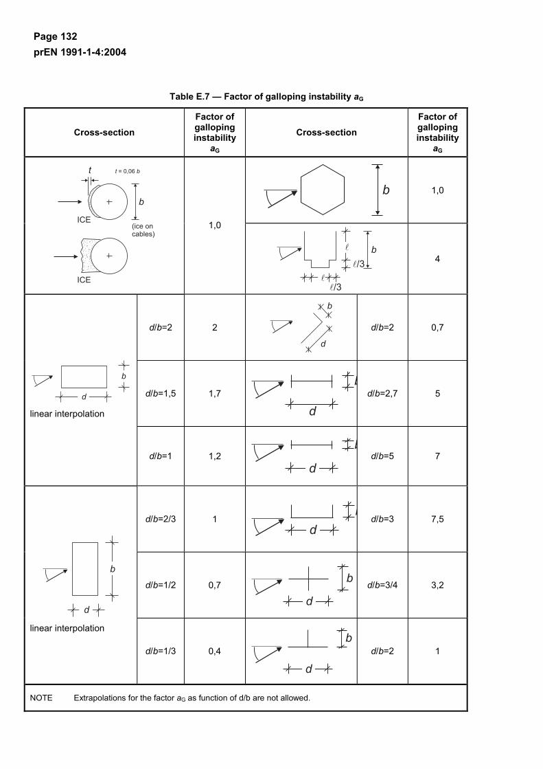
Page 132 prEN 1991-1-4:2004
Table E.7 — Factor of galloping instability aG
Cross-section Factor of galloping instability
aG
Cross-section Factor of galloping instability
aG
1,0
1,0
4
d/b=2 2
d/b=2 0,7
d/b=1,5 1,7 d/b=2,7 5
linear interpolation
d/b=1 1,2 d/b=5 7
d/b=2/3 1 d/b=3 7,5
d/b=1/2 0,7 d/b=3/4 3,2
linear interpolation
d/b=1/3 0,4 d/b=2 1
NOTE Extrapolations for the factor aG as function of d/b are not allowed.
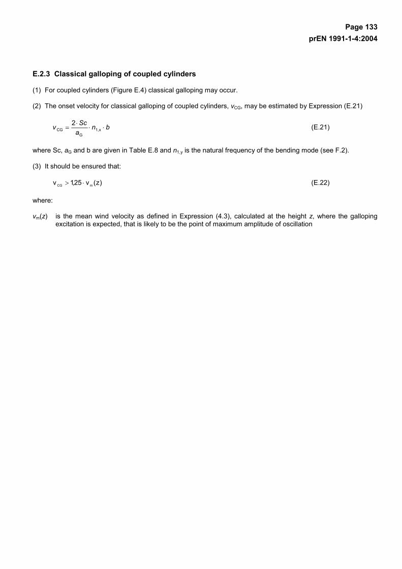
Page 133 prEN 1991-1-4:2004
E.2.3 Classical galloping of coupled cylinders
(1) For coupled cylinders (Figure E.4) classical galloping may occur.
(2) The onset velocity for classical galloping of coupled cylinders, vCG, may be estimated by Expression (E.21)
bnaScv ⋅⋅
⋅= x1,
GCG
2 (E.21)
where Sc, aG and b are given in Table E.8 and n1,y is the natural frequency of the bending mode (see F.2).
(3) It should be ensured that:
)z(v25,1v mCG ⋅> (E.22)
where:
vm(z) is the mean wind velocity as defined in Expression (4.3), calculated at the height z, where the galloping excitation is expected, that is likely to be the point of maximum amplitude of oscillation
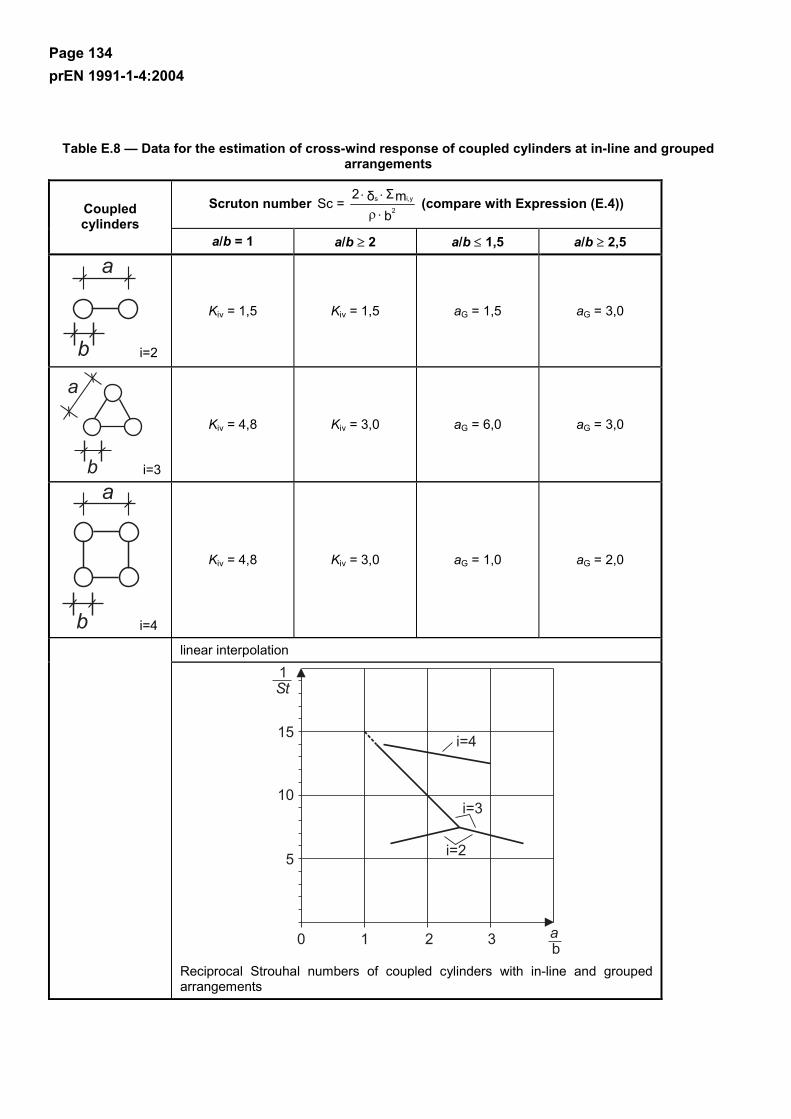
Page 134 prEN 1991-1-4:2004
Table E.8 — Data for the estimation of cross-wind response of coupled cylinders at in-line and grouped arrangements
Scruton number b
mΣδ2Sc =
2
i,ys
⋅ρ⋅⋅
(compare with Expression (E.4)) Coupled cylinders
a/b = 1 a/b ≥ 2 a/b ≤ 1,5 a/b ≥ 2,5
i=2
Kiv = 1,5 Kiv = 1,5 aG = 1,5 aG = 3,0
i=3
Kiv = 4,8 Kiv = 3,0 aG = 6,0 aG = 3,0
i=4
Kiv = 4,8 Kiv = 3,0 aG = 1,0 aG = 2,0
linear interpolation
Reciprocal Strouhal numbers of coupled cylinders with in-line and grouped arrangements
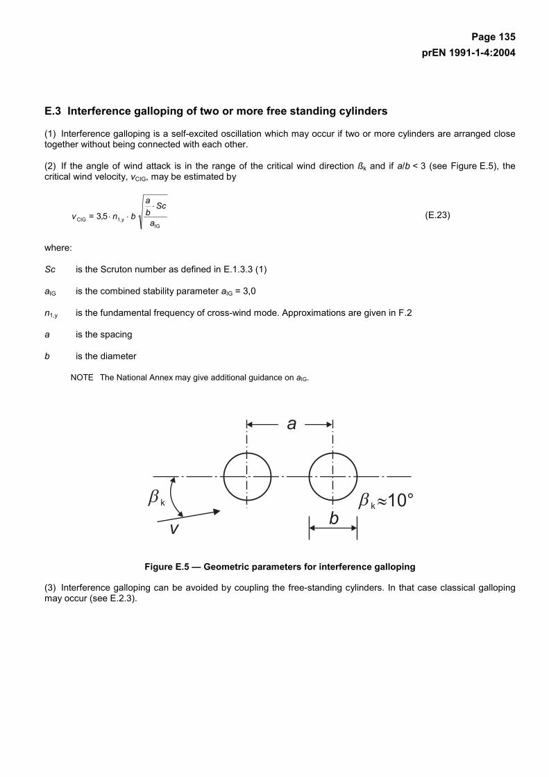
Page 135 prEN 1991-1-4:2004
E.3 Interference galloping of two or more free standing cylinders
(1) Interference galloping is a self-excited oscillation which may occur if two or more cylinders are arranged close together without being connected with each other.
(2) If the angle of wind attack is in the range of the critical wind direction ßk and if a/b < 3 (see Figure E.5), the critical wind velocity, vCIG, may be estimated by
IG
y1,CIG 53a
Scba
b n, = v⋅
⋅⋅ (E.23)
where:
Sc is the Scruton number as defined in E.1.3.3 (1)
aIG is the combined stability parameter aIG = 3,0
n1,y is the fundamental frequency of cross-wind mode. Approximations are given in F.2
a is the spacing
b is the diameter
NOTE The National Annex may give additional guidance on aIG.
Figure E.5 — Geometric parameters for interference galloping
(3) Interference galloping can be avoided by coupling the free-standing cylinders. In that case classical galloping may occur (see E.2.3).
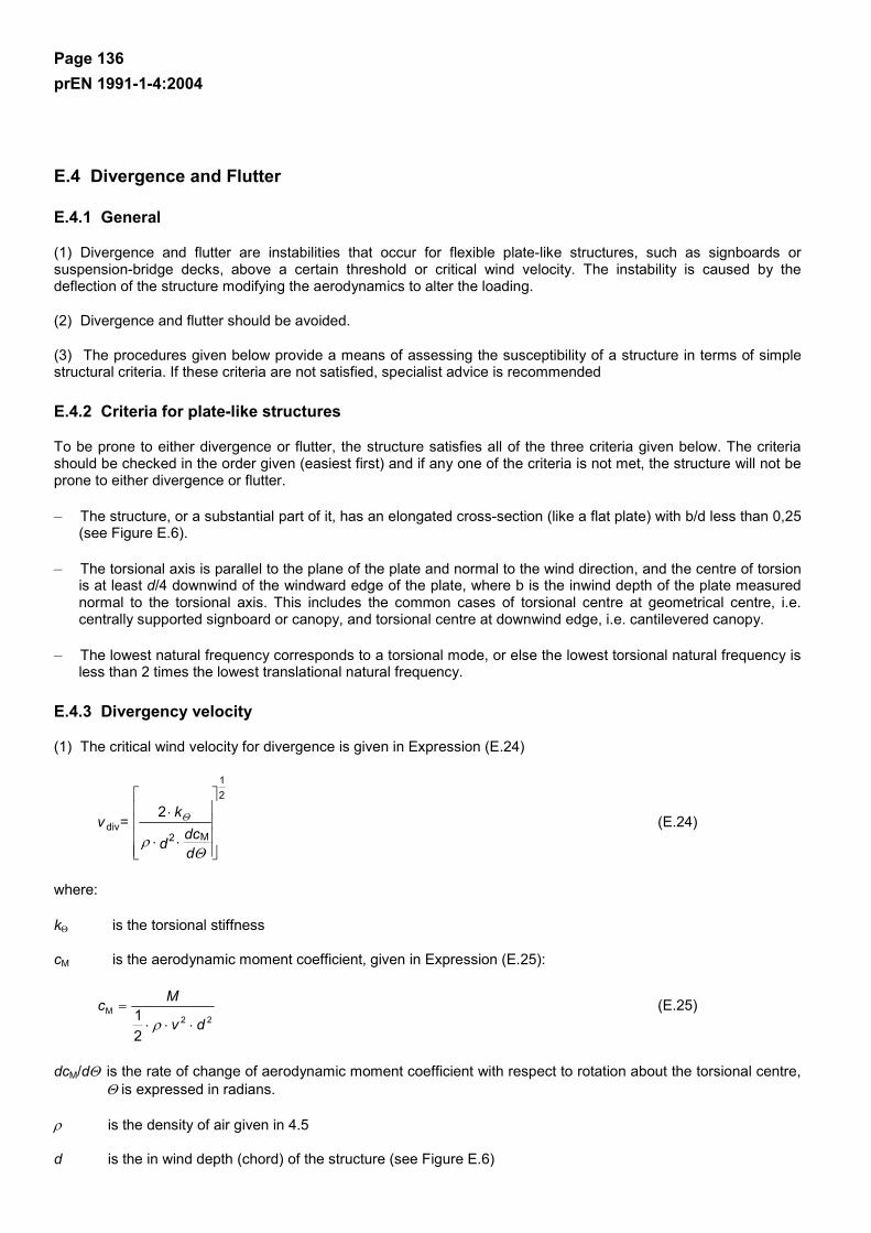
Page 136 prEN 1991-1-4:2004
E.4 Divergence and Flutter
E.4.1 General
(1) Divergence and flutter are instabilities that occur for flexible plate-like structures, such as signboards or suspension-bridge decks, above a certain threshold or critical wind velocity. The instability is caused by the deflection of the structure modifying the aerodynamics to alter the loading.
(2) Divergence and flutter should be avoided.
(3) The procedures given below provide a means of assessing the susceptibility of a structure in terms of simple structural criteria. If these criteria are not satisfied, specialist advice is recommended
E.4.2 Criteria for plate-like structures
To be prone to either divergence or flutter, the structure satisfies all of the three criteria given below. The criteria should be checked in the order given (easiest first) and if any one of the criteria is not met, the structure will not be prone to either divergence or flutter.
– The structure, or a substantial part of it, has an elongated cross-section (like a flat plate) with b/d less than 0,25 (see Figure E.6).
– The torsional axis is parallel to the plane of the plate and normal to the wind direction, and the centre of torsion is at least d/4 downwind of the windward edge of the plate, where b is the inwind depth of the plate measured normal to the torsional axis. This includes the common cases of torsional centre at geometrical centre, i.e. centrally supported signboard or canopy, and torsional centre at downwind edge, i.e. cantilevered canopy.
– The lowest natural frequency corresponds to a torsional mode, or else the lowest torsional natural frequency is less than 2 times the lowest translational natural frequency.
E.4.3 Divergency velocity
(1) The critical wind velocity for divergence is given in Expression (E.24)
⋅⋅
⋅
Θρ
Θ
ddcd
k= v
M2
21
div2
(E.24)
where:
kΘ is the torsional stiffness
cM is the aerodynamic moment coefficient, given in Expression (E.25):
22
M
21 dv
Mc⋅⋅⋅
=ρ
(E.25)
dcM/dΘ is the rate of change of aerodynamic moment coefficient with respect to rotation about the torsional centre, Θ is expressed in radians.
ρ is the density of air given in 4.5
d is the in wind depth (chord) of the structure (see Figure E.6)
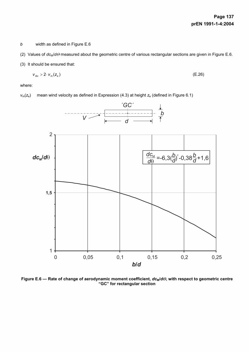
Page 137 prEN 1991-1-4:2004
b width as defined in Figure E.6
(2) Values of dcM/dΘ measured about the geometric centre of various rectangular sections are given in Figure E.6.
(3) It should be ensured that:
)(2 emdiv zvv ⋅> (E.26)
where:
vm(ze) mean wind velocity as defined in Expression (4.3) at height ze (defined in Figure 6.1)
Figure E.6 — Rate of change of aerodynamic moment coefficient, dcM/dΘ, with respect to geometric centre “GC” for rectangular section
Page 138 prEN 1991-1-4:2004
Annex F (informative)
Dynamic characteristics of structures
F.1 General
(1) Calculation procedures recommended in this section assume that structures possess linear elastic behaviour and classical normal modes. Dynamic structural properties are therefore characterised by:
– natural frequencies
– modal shapes
– equivalent masses
– logarithmic decrements of damping.
(2) Natural frequencies, modal shapes, equivalent masses and logarithmic decrements of damping should be evaluated, theoretically or experimentally, by applying the methods of structural dynamics.
(3) Fundamental dynamic properties can be evaluated in approximate terms, using simplified analytical, semi-empirical or empirical equations, provided they are adequately proved: Some of these equations are given in F.2 to F.5.
F.2 Fundamental frequency
(1) For cantilevers with one mass at the end a simplified expression to calculate the fundamental flexural frequency n1 of structures is given by Expression (F.1):
1
1 21
xgn ⋅
⋅=
π (F.1)
where:
g is the acceleration of gravity = 9,81 m/s²
x1 is the maximum displacement due to self weight applied in the vibration direction in m
(2) The fundamental flexural frequency n1 of multi-storey buildings with a height larger than 50 m can be estimated using Expression (F.2):
h
n 461 = [Hz] (F.2)
where:
h is the height of the structure in m
The same expression may give some guidance for single-storey buildings and towers.
(3) The fundamental flexural frequency n1, of chimneys can be estimated by Expression (F.3):
Page 139 prEN 1991-1-4:2004
t
s2eff
11 W
Wh
bn ⋅⋅
=ε [Hz] (F.3)
with:
3
21eff
hhh += (F.4)
where:
b is the top diameter of the chimney [m],
heff is the effective height of the chimney [m], h1 and h2 are given in Figure F.1,
Ws is the weight of structural parts contributing to the stiffness of the chimney,
Wt is the total weight of the chimney,
ε1 is equal to 1000 for steel chimneys, and 700 for concrete and masonry chimneys.
NOTE h3 = h1/3, seeF.4 (2)
Figure F.1 — Geometric parameters for chimneys
(4) The fundamental ovalling frequency n1,0 of a long cylindrical shell without stiffening rings may be calculated using Expression (F.5).
42s
3
0,1 )1(492,0
bEtn
⋅−⋅⋅
⋅=νµ
(F.5)
where:
E is Young's modulus in [N/m2]
t is the shell thickness in [m]
ν is Poisson ratio
µs is the mass of the shell per unit area in [kg/m2]
b is the diameter of the shell in [m]

Page 140 prEN 1991-1-4:2004
Expression (F.5) gives the lowest natural frequency of the shell. Stiffness rings increase n0.
(5) The fundamental vertical bending frequency n1,B of a plate or box girder bridge may be approximately derived from Expression (F.6).
m
EIL
Kn b2
2
B1, 2⋅
⋅⋅=
π (F.6)
where:
L is the length of the main span in m
E is Youngs Modulus in N/m2
Ib is the second moment of area of cross-section for vertical bending at mid-span in m4
m is the mass per unit length of the full cross-section ad midspan (for dead and super-imposed dead loads) in kg/m
K is a dimensionless factor depending on span arrangement defined below.
a) For single span bridges:
K = π if simply supported or K = 3,9 if propped cantilevered or K = 4,7 if encastre
b) For two-span continuous bridges:
K is obtained from Figure F.2, using the curve for two-span bridges, where
L1 is the length of the side span and L > L1.
c) For three-span continuous bridges:
K is obtained from Figure F.2, using the appropriate curve for three-span bridges, where
L1 is the length of the longest side span
L2 is the length of the other side span and L > L1 > L2
This also applies to three-span bridges with a cantilevered/suspended main span.
If L1 > L then K may be obtained from the curve for two span bridges, neglecting the shortest side span and treating the largest side span as the main span of an equivalent two-span bridge.
d) For symmetrical four-span continuous bridges (i.e. bridges symmetrical about the central support):
K may be obtained from the curve for two-span bridges in Figure F.2 treating each half of the bridge as an equivalent two-span bridge.
e) For unsymmetrical four-span continuous bridges and continuous bridges with more than four spans:
K may be obtained from Figure F.2 using the appropriate curve for three-span bridges, choosing the main span as the greatest internal span.
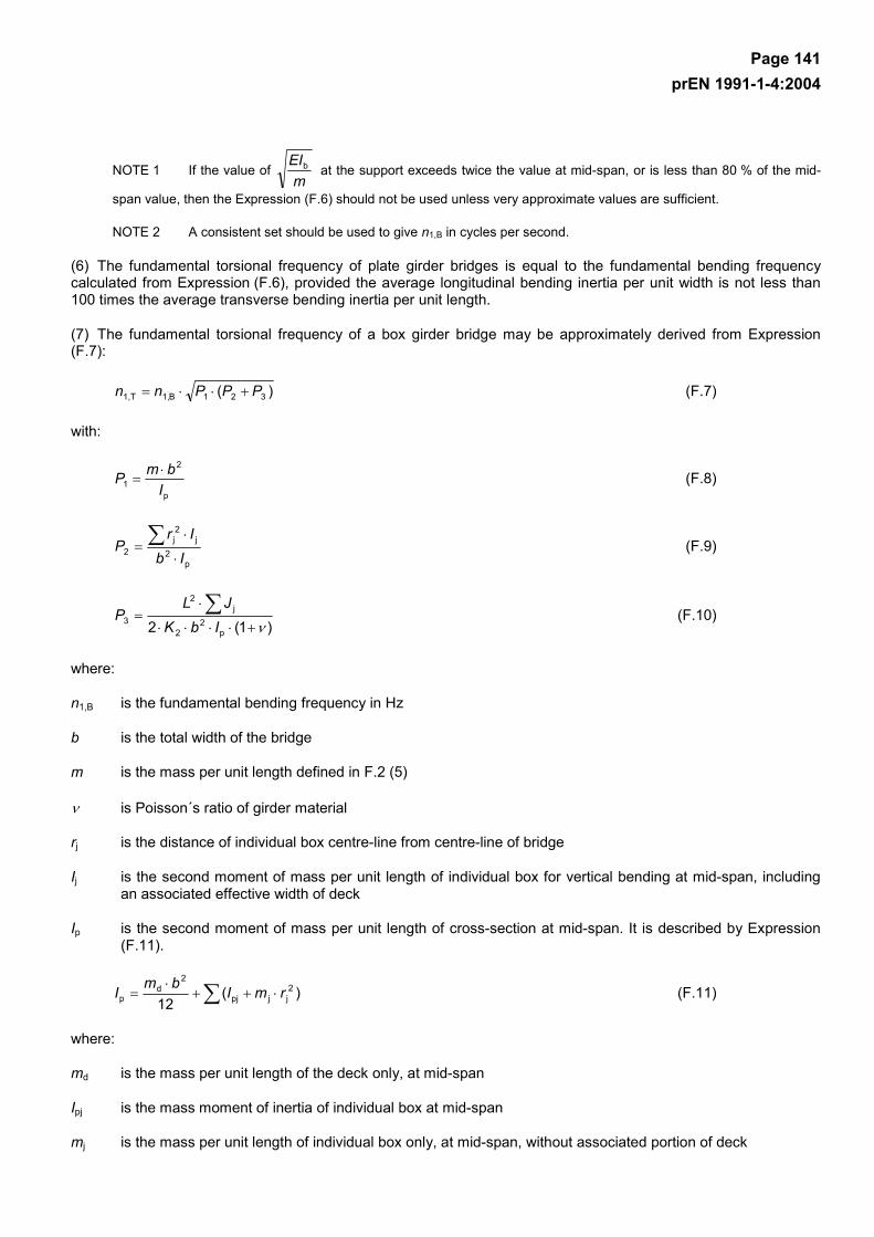
Page 141 prEN 1991-1-4:2004
NOTE 1 If the value of m
EIb at the support exceeds twice the value at mid-span, or is less than 80 % of the mid-
span value, then the Expression (F.6) should not be used unless very approximate values are sufficient.
NOTE 2 A consistent set should be used to give n1,B in cycles per second.
(6) The fundamental torsional frequency of plate girder bridges is equal to the fundamental bending frequency calculated from Expression (F.6), provided the average longitudinal bending inertia per unit width is not less than 100 times the average transverse bending inertia per unit length.
(7) The fundamental torsional frequency of a box girder bridge may be approximately derived from Expression (F.7):
)( 321B1,T1, PPPnn +⋅⋅= (F.7)
with:
p
2
1 IbmP ⋅
= (F.8)
p2
j2j
2 IbIr
P⋅
⋅= ∑ (F.9)
)1(2 p
22
j2
3 ν+⋅⋅⋅⋅
⋅= ∑
IbKJL
P (F.10)
where:
n1,B is the fundamental bending frequency in Hz
b is the total width of the bridge
m is the mass per unit length defined in F.2 (5)
ν is Poisson´s ratio of girder material
rj is the distance of individual box centre-line from centre-line of bridge
Ij is the second moment of mass per unit length of individual box for vertical bending at mid-span, including an associated effective width of deck
Ip is the second moment of mass per unit length of cross-section at mid-span. It is described by Expression (F.11).
∑ ⋅++⋅
= )(12
2jjpj
2d
p rmIbmI (F.11)
where:
md is the mass per unit length of the deck only, at mid-span
Ipj is the mass moment of inertia of individual box at mid-span
mj is the mass per unit length of individual box only, at mid-span, without associated portion of deck

Page 142 prEN 1991-1-4:2004
Jj is the torsion constant of individual box at mid-span. It is described by Expression (F.12).
∫
⋅=
tdsA
J2j
j
4 (F.12)
where:
Aj is the enclosed cell area at mid-span
∫ tds is the integral around box perimeter of the ratio length/thickness for each portion of box wall at mid-span
NOTE Slight loss of accuracy may occur if the proposed Expression (F.12) is applied to multibox bridges whose plan aspect ratio (=span/width) exceeds 6.
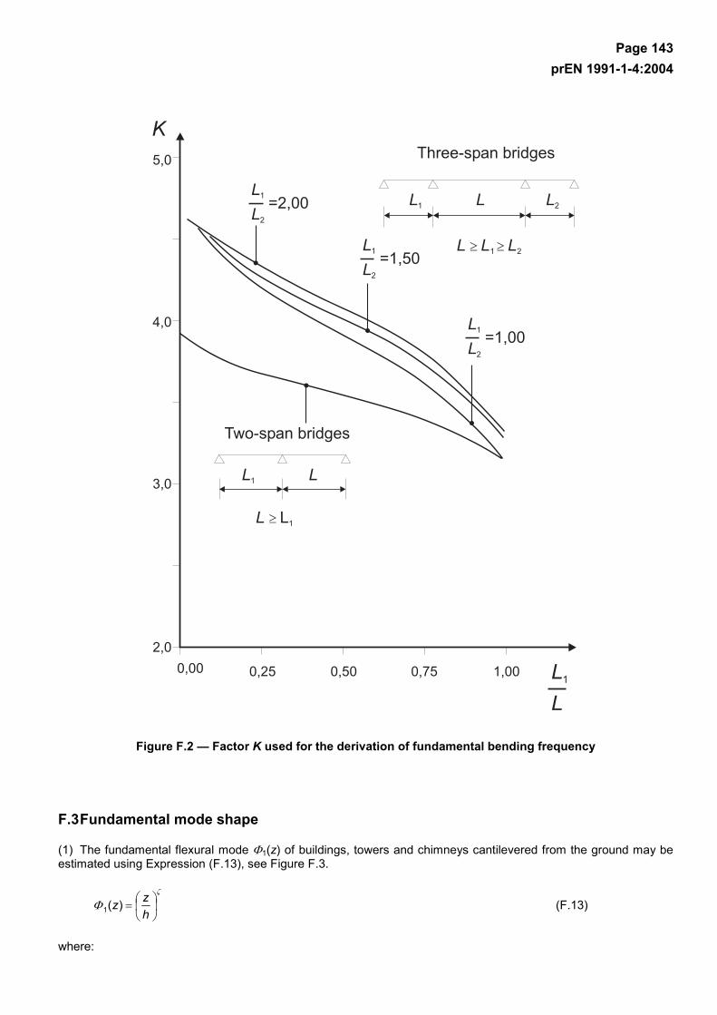
Page 143 prEN 1991-1-4:2004
Figure F.2 — Factor K used for the derivation of fundamental bending frequency
F.3 Fundamental mode shape
(1) The fundamental flexural mode Φ1(z) of buildings, towers and chimneys cantilevered from the ground may be estimated using Expression (F.13), see Figure F.3.
ζ
Φ
=hzz)(1 (F.13)
where:
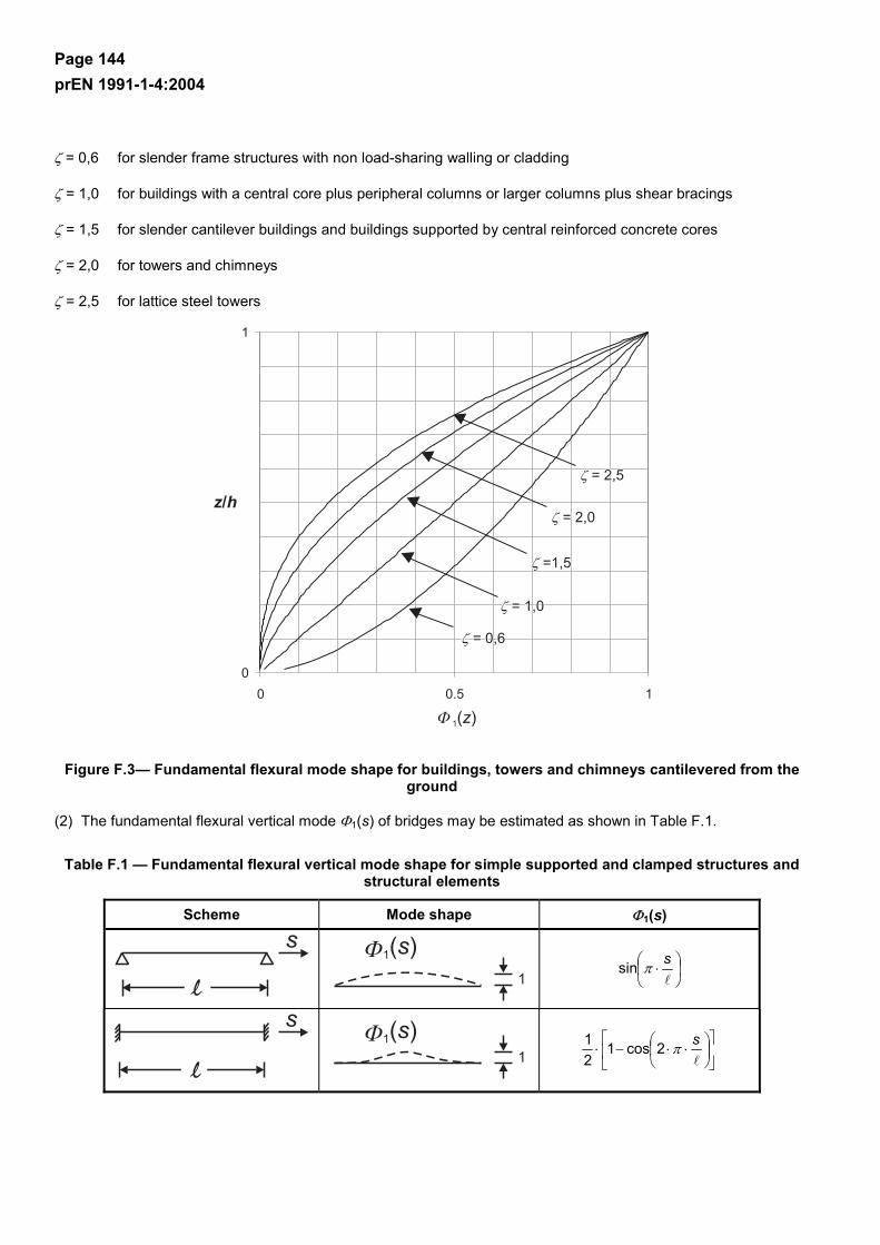
Page 144 prEN 1991-1-4:2004
ζ = 0,6 for slender frame structures with non load-sharing walling or cladding
ζ = 1,0 for buildings with a central core plus peripheral columns or larger columns plus shear bracings
ζ = 1,5 for slender cantilever buildings and buildings supported by central reinforced concrete cores
ζ = 2,0 for towers and chimneys
ζ = 2,5 for lattice steel towers
Figure F.3— Fundamental flexural mode shape for buildings, towers and chimneys cantilevered from the ground
(2) The fundamental flexural vertical mode Φ1(s) of bridges may be estimated as shown in Table F.1.
Table F.1 — Fundamental flexural vertical mode shape for simple supported and clamped structures and structural elements
Scheme Mode shape Φ1(s)
⋅
sπsin
⋅⋅−⋅
sπ2cos121
Page 145 prEN 1991-1-4:2004
F.4 Equivalent mass
(1) The equivalent mass per unit length me of the fundamental mode is given by Expression (F.14).
∫
∫ ⋅=
0
21
0
21
e
ds)(
ds)()(
s
ssmm
Φ
Φ (F.14)
where:
m is the mass per unit length
is the height or span of the structure or the structural element
i = 1 is the mode number
(2) For cantilevered structures with a varying mass distribution me may be approximated by the average value of m over the upper third of the structure h3 (see Figure F.1).
(3) For structures supported at both ends of span with a varying distribution of the mass per unit length me may
be approximated by the average value of m over a length of /3 centred at the point in the structure in which Φ(s) is maximum (see Table F.1).
F.5 Logarithmic decrement of damping
(1) The logarithmic decrement of damping δs for fundamental bending mode may be estimated by Expression (F.15).
das δδδδ ++= (F.15)
where:
δs is the logarithmic decrement of structural damping
δa is the logarithmic decrement of aerodynamic damping for the fundamental mode
δd is the logarithmic decrement of damping due to special devices (tuned mass dampers, sloshing tanks etc.)
(2) Approximate values of logarithmic decrement of structural damping, δs, are given in Table F.2.
(3) The logarithmic decrement of aerodynamic damping δa, for the fundamental bending mode of alongwind vibrations may be estimated by Expression (F.16).
e1
emfa 2
)(µ
ρδ
⋅⋅⋅⋅
=n
zvc (F.16)
where:
cf is the force coefficient for wind action in the wind direction stated in Section 7.
µe is the equivalent mass per unit area of the structure which for rectangular areas given by Expression (F.17).
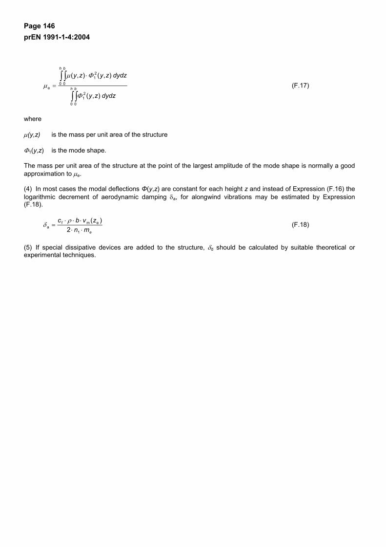
Page 146 prEN 1991-1-4:2004
∫ ∫
∫ ∫ ⋅
= h b
h b
dydzzy
dydzzyzy
0 0
21
0 0
21
e
),(
),(),(
Φ
Φµµ (F.17)
where
µ(y,z) is the mass per unit area of the structure
Φ1(y,z) is the mode shape.
The mass per unit area of the structure at the point of the largest amplitude of the mode shape is normally a good approximation to µe.
(4) In most cases the modal deflections Φ(y,z) are constant for each height z and instead of Expression (F.16) the logarithmic decrement of aerodynamic damping δa, for alongwind vibrations may be estimated by Expression (F.18).
emnzvbc
⋅⋅⋅⋅⋅
=1
emfa 2
)(ρδ (F.18)
(5) If special dissipative devices are added to the structure, δd should be calculated by suitable theoretical or experimental techniques.

Page 147 prEN 1991-1-4:2004
Table F.2 —Approximate values of logarithmic decrement of structural damping in the fundamental mode, δs
Structural type structural damping, δs
reinforced concrete buildings 0,10
steel buildings 0,05
mixed structures concrete + steel 0,08
reinforced concrete towers and chimneys 0,03
unlined welded steel stacks without external thermal insulation 0,012
unlined welded steel stack with external thermal insulation 0,020
h/b < 18 0,020
20≤h/b<24 0,040 steel stack with one liner with external thermal insulationa
h/b ≥ 26 0,014
h/b <18 0,020
20≤h/b<24 0,040 steel stack with two or more liners with external thermal insulation a
h/b ≥ 26 0,025
steel stack with internal brick liner 0,070
steel stack with internal gunite 0,030
coupled stacks without liner 0,015
guyed steel stack without liner 0,04
welded 0,02
high resistance bolts 0,03 steel bridges + lattice steel towers
ordinary bolts 0,05
composite bridges 0,04
prestressed without cracks 0,04 concrete bridges
with cracks 0,10
Timber bridges 0,06 - 0,12
Bridges, aluminium alloys 0,02
Bridges, glass or fibre reinforced plastic 0,04 - 0,08
parallel cables 0,006 cables
spiral cables 0,020
NOTE 1 The values for timber and plastic composites are indicative only. In cases where aerodynamic effects are found to be significant in the design, more refinded figures are needed through specialist advice (agreed if appropriate with the competent Authority.
NOTE 2 For cable supported bridges the values given in Table F.2 need to be factored by 0,75
a For intermediate values of h/b, linear interpolation may be used

Page 148 prEN 1991-1-4:2004
Bibliography ISO 2394 General principles on reliability for structures ISO 3898 General principles on reliability for structures ISO 8930 General principles on reliability for structures - List of equivalent terms ISO FDIS12494

EUROPEAN STANDARD
NORME EUROPÉENNE
EUROPÄISCHE NORM
EN 1991-1-5
November 2003
ICS 91.010.30 Supersedes ENV 1991-2-5:1997
English version
Eurocode 1: Actions on structures - Part 1-5: General actions -Thermal actions
Eurocode 1: Actions sur les structures - Partie 1-5: Actionsgénérales – Actions thermiques
This European Standard was approved by CEN on 18 September 2003.
CEN members are bound to comply with the CEN/CENELEC Internal Regulations which stipulate the conditions for giving this EuropeanStandard the status of a national standard without any alteration. Up-to-date lists and bibliographical references concerning such nationalstandards may be obtained on application to the Management Centre or to any CEN member.
This European Standard exists in three official versions (English, French, German). A version in any other language made by translationunder the responsibility of a CEN member into its own language and notified to the Management Centre has the same status as the officialversions.
CEN members are the national standards bodies of Austria, Belgium, Czech Republic, Denmark, Finland, France, Germany, Greece,Hungary, Iceland, Ireland, Italy, Luxembourg, Malta, Netherlands, Norway, Portugal, Slovakia, Spain, Sweden, Switzerland and UnitedKingdom.
EUROPEAN COMMITTEE FOR STANDARDIZATIONC OM ITÉ EUR OP ÉEN DE NOR M ALIS AT IONEUROPÄISCHES KOMITEE FÜR NORMUNG
Management Centre: rue de Stassart, 36 B-1050 Brussels
© 2003 CEN All rights of exploitation in any form and by any means reservedworldwide for CEN national Members.
Ref. No. EN 1991-1-5:2003 E
EN 1991-1-5: 2003 (E)
2
CONTENTS Page
FOREWORD .............................................................................................................. 4
BACKGROUND TO THE EUROCODE PROGRAMME........................................................... 4STATUS AND FIELD OF APPLICATION OF EUROCODES..................................................... 5NATIONAL STANDARDS IMPLEMENTING EUROCODES ..................................................... 6LINKS BETWEEN EUROCODES AND PRODUCT HARMONIZED TECHNICAL SPECIFICATIONS
(ENS AND ETAS)....................................................................................................... 6ADDITIONAL INFORMATION SPECIFIC TO EN 1991-1-5................................................... 6NATIONAL ANNEX FOR EN 1991-1-5 ........................................................................... 7
SECTION 1 GENERAL............................................................................................. 8
1.1 SCOPE ............................................................................................................. 81.2 NORMATIVE REFERENCES .................................................................................. 81.3 ASSUMPTIONS................................................................................................... 81.4 DISTINCTION BETWEEN PRINCIPLES AND APPLICATION RULES ................................ 91.5 DEFINITIONS ..................................................................................................... 91.6 SYMBOLS ....................................................................................................... 10
SECTION 2 CLASSIFICATION OF ACTIONS ....................................................... 13
SECTION 3 DESIGN SITUATIONS........................................................................ 14
SECTION 4 REPRESENTATION OF ACTIONS .................................................... 15
SECTION 5 TEMPERATURE CHANGES IN BUILDINGS..................................... 16
5.1 GENERAL .......................................................................................................... 165.2 DETERMINATION OF TEMPERATURES.................................................................... 165.3 DETERMINATION OF TEMPERATURE PROFILES ....................................................... 17
SECTION 6 TEMPERATURE CHANGES IN BRIDGES ........................................ 19
6.1 BRIDGE DECKS................................................................................................ 196.1.1 Bridge deck types ................................................................................... 196.1.2 Consideration of thermal actions ............................................................... 196.1.3 Uniform temperature component ............................................................... 196.1.4 Temperature difference components ...................................................... 236.1.5 Simultaneity of uniform and temperature difference components........... 296.1.6 Differences in the uniform temperature component between differentstructural elements ............................................................................................. 30
6.2 BRIDGE PIERS ................................................................................................ 306.2.1 Consideration of thermal actions ............................................................ 306.2.2 Temperature differences......................................................................... 30
SECTION 7 TEMPERATURE CHANGES IN INDUSTRIAL CHIMNEYS,PIPELINES, SILOS, TANKS AND COOLING TOWERS......................................... 31
7.1 GENERAL ....................................................................................................... 317.2 TEMPERATURE COMPONENTS........................................................................... 31
7.2.1 Shade air temperature ............................................................................ 317.2.2 Flue gas, heated liquids and heated materials temperature ................... 32
EN 1991-1-5: 2003 (E)
3
7.2.3 Element temperature .............................................................................. 327.3 CONSIDERATION OF TEMPERATURE COMPONENTS.............................................. 327.4 DETERMINATION OF TEMPERATURE COMPONENTS.............................................. 327.5 VALUES OF TEMPERATURE COMPONENTS (INDICATIVE VALUES) ........................... 337.6 SIMULTANEITY OF TEMPERATURE COMPONENTS................................................. 33
ANNEX A (NORMATIVE) ISOTHERMS OF NATIONAL MINIMUM AND MAXIMUMSHADE AIR TEMPERATURES ............................................................................... 36
A.1 GENERAL ....................................................................................................... 36A.2 MAXIMUM AND MINIMUM SHADE AIR TEMPERATURE VALUES WITH AN ANNUALPROBABILITY OF BEING EXCEEDED P OTHER THAN 0,02................................................ 36
ANNEX B (NORMATIVE) TEMPERATURE DIFFERENCES FOR VARIOUSSURFACING DEPTHS............................................................................................. 39
ANNEX C (INFORMATIVE) COEFFICIENTS OF LINEAR EXPANSION ............... 42
ANNEX D (INFORMATIVE) TEMPERATURE PROFILES IN BUILDINGS ANDOTHER CONSTRUCTION WORKS ........................................................................ 44
BIBLIOGRAPHY ...................................................................................................... 46

EN 1991-1-5: 2003 (E)
4
Foreword
This document (EN 1991-1-5) has been prepared by Technical CommitteeCEN/TC250 "Structural Eurocodes", the secretariat of which is held by BSI.
This European Standard shall be given the status of a national standard, either bypublication of an identical text or by endorsement, at the latest by May 2004, andconflicting national standards shall be withdrawn at the latest by March 2010.
Annexes A and B are normative. Annexes C and D are informative.
This document supersedes ENV 1991-2-5:1997.
According to the CEN/CENELEC Internal Regulations, the national standardsorganizations of the following countries are bound to implement this EuropeanStandard: Austria, Belgium, Czech Republic, Denmark, Finland, France, Germany,Greece, Hungary, Iceland, Ireland, Italy, Luxembourg, Malta, Netherlands, Norway,Portugal, Slovakia, Spain, Sweden, Switzerland and the United Kingdom.
Background to the Eurocode Programme
In 1975, the Commission of the European Communities decided on an actionprogramme in the field of construction, based on article 95 of the treaty. Theobjective of the programme was the elimination of technical obstacles to trade andthe harmonization of technical specifications.
Within this action programme, the Commission took the initiative to establish a set ofharmonised technical rules for the design of construction works which, in a firststage, would serve as an alternative to the national rules in force in the MemberStates and, ultimately, would replace them.
For fifteen years, the Commission, with the help of a Steering Committee withRepresentatives of Member States, conducted the development of the Eurocodesprogramme, which led to the first generation of European codes in the 1980's.
In 1989, the Commission and the Member States of the EU and EFTA decided, onthe basis of an agreement between the Commission and CEN, to transfer thepreparation and the publication of the Eurocodes to CEN through a series ofmandates, in order to provide them with a future status of European Standard (EN).This links de facto the Eurocode with the provisions of all the Council's Directivesand/or Commission's Decisions dealing with European Standards (e.g. the CouncilDirective 89/106/EEC on construction products - CPD - and Council Directives93/37/EEC, 92/50/EEC and 89/440/EEC on public works and services and equivalentEFTA Directives initiated in pursuit of settings up the internal market).
The Structural Eurocode programme comprises the following standards generallyconsisting of a number of Parts:

EN 1991-1-5: 2003 (E)
5
EN 1990 Eurocode: Basis of Structural DesignEN 1991 Eurocode 1: Actions on structuresEN 1992 Eurocode 2: Design of concrete structuresEN 1993 Eurocode 3: Design of steel structuresEN 1994 Eurocode 4: Design of composite steel and concrete structuresEN 1995 Eurocode 5: Design of timber structuresEN 1996 Eurocode 6: Design of masonry structuresEN 1997 Eurocode 7: Geotechnical designEN 1998 Eurocode 8: Design of structures for earthquake resistanceEN 1999 Eurocode 9: Design of aluminium alloy structures
Eurocode standards recognize the responsibility of regulatory authorities in eachMember State and have safeguarded their right to determine values related toregulatory safety matters at national level where these continue to vary from State toState.
Status and field of application of Eurocodes
The Member States of the EU and EFTA recognize that Eurocodes serve asreference documents for the following purposes:
– as a means of providing compliance of building and civil engineering works withthe essential requirements of Council Directive 89/106/EEC, particularly EssentialRequirement No1 - Mechanical resistance and stability - and EssentialRequirement No2 - Safety in case of fire;
– as a basis for specifying contracts for construction works and related engineeringservices;
– as a framework for drawing up harmonized technical specifications forconstruction products (ENs and ETAs)
The Eurocodes, as far as they concern the construction works themselves, have adirect relationship with the Interpretative Documents referred to in Article 12 of theCPD, although they are of a different nature from harmonized product standards.Therefore, technical aspects arising from the Eurocodes work need to be adequatelyconsidered by CEN Technical Committees and/or EOTA Working Groups working onproduct standards with a view to achieving a full compatibility of these technicalspecifications with the Eurocodes.
The Eurocode standards provide common structural design rules for everyday usefor the design of whole structures and component products of both a traditional andan innovative nature. Unusual forms of construction design conditions are notspecifically covered and additional expert consideration will be required by thedesigner in such cases.

EN 1991-1-5: 2003 (E)
6
National Standards implementing Eurocodes
The National Standards implementing Eurocodes will comprise the full text of theEurocode (including any annexes), as published by CEN, which may be preceded bya National title page and National foreword, and may be followed by a National annex(informative).
The National annex (informative) may only contain information on those parameterswhich are left open in the Eurocode for national choice, known as NationallyDetermined parameters, to be used for the design of buildings and civil engineeringworks to be constructed in the country concerned, i.e.:
– values and/or classes where alternatives are given in the Eurocode,– values to be used where a symbol only is given in the Eurocode,– country specific data (geographical, climatic, etc.), e.g. snow map,– the procedure to be used where alternative procedures are given in the EN
Eurocode.It may also contain– decisions on the application of informative annexes,– references to non-contradictory complementary information to assist the user to
apply the Eurocode.
Links between Eurocodes and product harmonized technical specifications(ENs and ETAs)
There is a need for consistency between the harmonized technical specifications forconstruction products and the technical rules for works. Furthermore, all theinformation accompanying the CE Marking of the construction products which refer toEurocodes should clearly mention which Nationally Determined Parameters havebeen taken into account.
Additional information specific to EN 1991-1-5
EN 1991-1-5 gives design guidance for thermal actions arising from climatic andoperational conditions on buildings and civil engineering works.
Information on thermal actions induced by fire is given in EN 1991-1-2.
EN 1991-1-5 is intended for clients, designers, contractors and relevant authorities. EN 1991-1-5 is intended to be used with EN 1990, the other Parts of EN 1991 andEN 1992-1999 for the design of structures. In the case of bridges, the National annexes specify whether the general non-linearor the simplified linear temperature components should be used in designcalculations.

EN 1991-1-5: 2003 (E)
7
In the case of chimneys, references should be made to EN 13084-1 for thermalactions from operating processes.
National annex for EN 1991-1-5
This standard gives alternative procedures, values and recommendations for classeswith notes indicating where national choices may have to be made. Therefore theNational Standard implementing EN 1991-1-5 should have a National annexcontaining all Nationally Determined Parameters to be used for the design ofbuildings and civil engineering works to be constructed in the relevant country.
National choice is allowed in EN 1991-1-5 through clauses:
- 5.3(2) (Tables 5.1, 5.2 and 5.3)- 6.1.1 (1)- 6.1.2(2)- 6.1.3.1(4)- 6.1.3.2(1)- 6.1.3.3(3)- 6.1.4(3)- 6.1.4.1(1)- 6.1.4.2(1)- 6.1.4.3(1)- 6.1.4.4(1)- 6.1.5(1)- 6.1.6(1)- 6.2.1(1)P- 6.2.2(1)- 6.2.2(2)- 7.2.1(1)- 7.5(3)- 7.5(4)- A.1(1)- A.1(3)- A.2(2)- B(1) (Tables B.1, B.2 and B.3)
EN 1991-1-5: 2003 (E)
8
Section 1 General
1.1 Scope
(1) EN 1991-1-5 gives principles and rules for calculating thermal actions onbuildings, bridges and other structures including their structural elements. Principlesneeded for cladding and other appendages of buildings are also provided.
(2) This Part describes the changes in the temperature of structural elements.Characteristic values of thermal actions are presented for use in the design ofstructures which are exposed to daily and seasonal climatic changes. Structures notso exposed may not need to be considered for thermal actions.
(3) Structures in which thermal actions are mainly a function of their use (e.g. coolingtowers, silos, tanks, warm and cold storage facilities, hot and cold services etc) aretreated in Section 7. Chimneys are treated in EN 13084-1.
1.2 Normative references
This European Standard incorporates, by dated or undated reference, provisionsfrom other publications. These normative references are cited at the appropriateplaces in the text and the publications are listed hereafter. For dated references,subsequent amendments to or revisions of any of these publications apply to thisEuropean Standard only when incorporated in it by amendment or revision. Forundated references the latest edition of the publication referred to applies (includingamendments).
EN 1990:2002 Eurocode: Basis of structural design
prEN 1991-1-6 Eurocode 1: Actions on structuresPart 1.6: General actions - Actions during execution
EN 13084-1 Free-standing industrial chimneysPart 1: General requirements
ISO 2394 General principles on reliability for structures
ISO 3898 Bases of design of structures - Notations. General symbols
ISO 8930 General principles on reliability for structures. List of equivalent terms
1.3 Assumptions
(1)P The general assumptions of EN 1990 also apply to this Part.
EN 1991-1-5: 2003 (E)
9
1.4 Distinction between principles and application rules
(1)P The rules in EN 1990:2002, 1.4 also apply to this Part.
1.5 Terms and definitions
For the purposes of this European Standard, the definitions given in EN 1990,ISO 2394, ISO 3898 and ISO 8930 and the following apply.
1.5.1thermal actionsthermal actions on a structure or a structural element are those actions that arisefrom the changes of temperature fields within a specified time interval
1.5.2shade air temperaturethe shade air temperature is the temperature measured by thermometers placed in awhite painted louvred wooden box known as a “Stevenson screen”
1.5.3maximum shade air temperature Tmax
value of maximum shade air temperature with an annual probability of beingexceeded of 0,02 (equivalent to a mean return period of 50 years), based on themaximum hourly values recorded
1.5.4minimum shade air temperature Tmin
value of minimum shade air temperature with an annual probability of beingexceeded of 0,02 (equivalent to a mean return period of 50 years), based on theminimum hourly values recorded
1.5.5initial temperature T0
the temperature of a structural element at the relevant stage of its restraint(completion)
1.5.6claddingthe part of the building which provides a weatherproof membrane. Generally claddingwill only carry self weight and/or wind actions
1.5.7uniform temperature componentthe temperature, constant over the cross section, which governs the expansion orcontraction of an element or structure (for bridges this is often defined as the“effective” temperature, but the term “uniform” has been adopted in this part)
EN 1991-1-5: 2003 (E)
10
1.5.8temperature difference componentthe part of a temperature profile in a structural element representing the temperaturedifference between the outer face of the element and any in-depth point
1.6 Symbols
(1) For the purposes of this Part of Eurocode 1, the following symbols apply.
NOTE: The notation used is based on ISO 3898
(2) A basic list of notations is provided in EN 1990, and the additional notations beloware specific to this Part.
Latin upper case letters
R thermal resistance of structural element
Rin thermal resistance at the inner surface
Rout thermal resistance at the outer surface
Tmax maximum shade air temperature with an annual probability of beingexceeded of 0,02 (equivalent to a mean return period of 50 years)
Tmin minimum shade air temperature with an annual probability of beingexceeded of 0,02 (equivalent to a mean return period of 50 years)
Tmax,p maximum shade air temperature with an annual probability of beingexceeded p (equivalent to a mean return period of 1/p)
Tmin,p minimum shade air temperature with an annual probability of beingexceeded p (equivalent to a mean return period of 1/p)
Te.max maximum uniform bridge temperature component
Te.min minimum uniform bridge temperature component
T0 initial temperature when structural element is restrained
Tin air temperature of the inner environment
Tout temperature of the outer environment
∆T1, ∆T2, values of heating (cooling) temperature differences∆T3, ∆ T4
EN 1991-1-5: 2003 (E)
11
∆TU uniform temperature component
∆TN, exp maximum expansion range of uniform bridge temperature component
(Te.max ≥ T0)
∆TN, con maximum contraction range of uniform bridge temperature component(T0 ≥ Te.min)
∆TN overall range of uniform bridge temperature component
∆TM linear temperature difference component
∆TM,heat linear temperature difference component (heating)
∆TM,cool linear temperature difference component (cooling)
∆TE non-linear part of the temperature difference component
∆T sum of linear temperature difference component and non-linear part ofthe temperature difference component
∆Tp temperature difference between different parts of a structure given bythe difference of average temperatures of these parts
Latin lower case letters
h height of the cross-section
k1,k2 coefficients for calculation of maximum (minimum) shade airk3,k4 temperature with an annual probability of being exceeded, p, other than
0,02
ksur surfacing factor for linear temperature difference component
p annual probability of maximum (minimum) shade air temperature beingexceeded (equivalent to a mean return period of 1/p years)
u,c mode and scale parameter of annual maximum (minimum)shade air temperature distribution
Greek lower case letters
αT coefficient of linear expansion (1/°C)
λ thermal conductivity

EN 1991-1-5: 2003 (E)
12
ωN reduction factor of uniform temperature component for combinationwith temperature difference component
ωM reduction factor of temperature difference component for combinationwith uniform temperature component
EN 1991-1-5: 2003 (E)
13
Section 2 Classification of actions
(1)P Thermal actions shall be classified as variable and indirect actions, see EN1990:2002, 1.5.3 and 4.1.1.
(2) All values of thermal actions given in this Part are characteristic values unless it isstated otherwise.
(3) Characteristic values of thermal actions as given in this Part are values with anannual probability of being exceeded of 0,02, unless otherwise stated, e.g. fortransient design situations.
NOTE: For transient design situations, the related values of thermal actions may be derivedusing the calculation method given in A.2.

EN 1991-1-5: 2003 (E)
14
Section 3 Design situations
(1)P Thermal actions shall be determined for each relevant design situation identifiedin accordance with EN 1990.
NOTE: Structures not exposed to daily and seasonal climatic and operational temperaturechanges may not need to be considered for thermal actions.
(2)P The elements of loadbearing structures shall be checked to ensure that thermalmovement will not cause overstressing of the structure, either by the provision ofmovement joints or by including the effects in the design.
EN 1991-1-5: 2003 (E)
15
Section 4 Representation of actions
(1) Daily and seasonal changes in shade air temperature, solar radiation, re-radiation, etc., will result in variations of the temperature distribution within individualelements of a structure.
(2) The magnitude of the thermal effects will be dependent on local climaticconditions, together with the orientation of the structure, its overall mass, finishes(e.g. cladding in buildings), and in the case of building structures, heating andventilation regimes and thermal insulation.
(3) The temperature distribution within an individual structural element may be splitinto the following four essential constituent components, as illustrated in Figure 4.1:
a) A uniform temperature component, ∆Tu ;
b) A linearly varying temperature difference component about the z-z axis, ∆TMY ;
c) A linearly varying temperature difference component about the y-y axis, ∆TMZ ;
d) A non-linear temperature difference component, ∆TE. This results in a system ofself-equilibrated stresses which produce no net load effect on the element.
Figure 4.1: Diagrammatic representation of constituent components of atemperature profile
(4) The strains and therefore any resulting stresses, are dependent on the geometryand boundary conditions of the element being considered and on the physicalproperties of the material used. When materials with different coefficients of linearexpansion are used compositely the thermal effect should be taken into account.
(5) For the purpose of deriving thermal effects, the coefficient of linear expansion fora material should be used.
NOTE: The coefficient of linear expansion for a selection of commonly used materials isgiven in annex C.
EN 1991-1-5: 2003 (E)
16
Section 5 Temperature changes in buildings
5.1 General
(1)P Thermal actions on buildings due to climatic and operational temperaturechanges shall be considered in the design of buildings where there is a possibility ofthe ultimate or serviceability limit states being exceeded due to thermal movementand/or stresses.
NOTE 1: Volume changes and/or stresses due to temperature changes may also beinfluenced by:
a) shading of adjacent buildings,
b) use of different materials with different thermal expansion coefficients and heat transfer,
c) use of different shapes of cross-section with different uniform temperature.
NOTE 2: Moisture and other environmental factors may also affect the volume changes ofelements.
5.2 Determination of temperatures
(1) Thermal actions on buildings due to climatic and operational temperaturechanges should be determined in accordance with the principles and rules providedin this Section taking into account national (regional) data and experience.
(2)P The climatic effects shall be determined by considering the variation of shade airtemperature and solar radiation. Operational effects (due to heating, technological orindustrial processes) shall be considered in accordance with the particular project.
(3)P In accordance with the temperature components given in Section 4, climatic andoperational thermal actions on a structural element shall be specified using thefollowing basic quantities:
a) A uniform temperature component ∆Tu given by the difference between theaverage temperature T of an element and its initial temperature T0.
b) A linearly varying temperature component given by the difference ∆TM betweenthe temperatures on the outer and inner surfaces of a cross section, or on thesurfaces of individual layers.
c) A temperature difference ∆Tp of different parts of a structure given by thedifference of average temperatures of these parts.
NOTE: Values of ∆TM and ∆Tp may be provided for the particular project.
(4) In addition to ∆Tu, ∆TM and ∆Tp, local effects of thermal actions should beconsidered where relevant (e.g. at supports or fixings of structural and cladding
EN 1991-1-5: 2003 (E)
17
elements). Adequate representation of thermal actions should be defined taking intoaccount the location of the building and structural detailing.
(5) The uniform temperature component of a structural element ∆Tu is defined as:
∆Tu = T – T0 (5.1)
where:
T is an average temperature of a structural element due to climatic temperaturesin winter or summer season and due to operational temperatures.
(6) The quantities ∆Tu, ∆TM, ∆Tp, and T should be determined in accordance with theprinciples provided in 5.3 using regional data. When regional data are not available,the rules in 5.3 may be applied.
5.3 Determination of temperature profiles
(1) The temperature T in Expression (5.1) should be determined as the averagetemperature of a structural element in winter or summer using a temperature profile.In the case of a sandwich element T is the average temperature of a particular layer.
NOTE 1: Methods of the thermal transmission theory are indicated in annex D.
NOTE 2: When elements of one layer are considered and when the environmental conditionson both sides are similar, T may be approximately determined as the average of inner andouter environment temperature T
in and T
out.
(2) The temperature of the inner environment, Tin , should be determined inaccordance with Table 5.1. The temperature of the outer environment, Tout , shouldbe determined in accordance with:
a) Table 5.2 for parts located above ground level,
b) Table 5.3 for underground parts.
NOTE: The temperatures Tout
for the summer season as indicated in Table 5.2 aredependent on the surface absorptivity and its orientation:
– the maximum is usually reached for surfaces facing the west, south-west or for horizontalsurfaces,
– the minimum (in 0C about half of the maximum) for surfaces facing the north.
EN 1991-1-5: 2003 (E)
18
Table 5.1: Indicative temperatures of inner environment Tin
Season Temperature Tin
Summer T1
Winter T2
NOTE: Values for T1 and T
2 may be specified in the National Annex. When no data are
available the values T1 = 20 °C and T
2 = 25 °C are recommended.
Table 5.2: Indicative temperatures Tout for buildings above the ground levelSeason Significant factor Temperature T
out in 0C
0,5bright light surface
Tmax
+ T3
0,7light coloured surface
Tmax
+ T4
Summer
Relativeabsorptivitydepending onsurface colour
0,9dark surface
Tmax
+ T5
Winter Tmin
NOTE: Values of the maximum shade air temperature Tmax
, minimum shade air shadetemperature T
min, and solar radiation effects T
3, T
4, and T
5 may be specified in the NationalAnnex. If no data are available for regions between latitudes 45oN and 55oN the values T
3
= 0°C, T4 = 2°C, and T
5 = 4°C are recommended, , for North-East facing elements and T
3
= 18°C, T4 = 30°C, and T
5 = 42°C for South-West or horizontal facing elements.
Table 5.3: Indicative temperatures Tout for underground parts of buildings
Season Depth below the ground level Temperature Tout
in 0C
Less than 1 m T6
Summer
More than 1 m T7
Less than 1 m T8
Winter
More than 1 m T9
NOTE: Values T6, T
7, T
8, and T9 may be specified in the National Annex. If no data are
available for regions between latitudes 45oN and 55oN the values T6 = 8°C, T
7 = 5°C, T
8
= -5°C and T9 = -3°C are recommended.
EN 1991-1-5: 2003 (E)
19
Section 6 Temperature changes in bridges
6.1 Bridge decks
6.1.1 Bridge deck types
(1) For the purposes of this Part, bridge decks are grouped as follows:
Type 1 Steel deck: - steel box girder- steel truss or plate girder
Type 2 Composite deck
Type 3 Concrete deck: - concrete slab- concrete beam- concrete box girder
NOTE 1: See also Figure 6.2.
NOTE 2: The National Annex may specify values of the uniform temperature component andthe temperature difference component for other types of bridges.
6.1.2 Consideration of thermal actions
(1) Representative values of thermal actions should be assessed by the uniformtemperature component (see 6.1.3) and the temperature difference components (see6.1.4).
(2) The vertical temperature difference component given in 6.1.4 should generallyinclude the non-linear component, see 4(3). Either Approach 1 (see 6.1.4.1) orApproach 2 (see 6.1.4.2) should be used.
NOTE: The selection of the approach to be used in a Country may be found in its NationalAnnex.
(3) Where a horizontal temperature difference needs to be considered a lineartemperature difference component may be assumed in the absence of otherinformation (see 6.1.4.3).
6.1.3 Uniform temperature component
6.1.3.1 General
(1) The uniform temperature component depends on the minimum and maximumtemperature which a bridge will achieve. This results in a range of uniform
EN 1991-1-5: 2003 (E)
20
temperature changes which, in an unrestrained structure would result in a change inelement length.
(2) The following effects should be taken into account where relevant:
– Restraint of associated expansion or contraction due to the type of construction(e.g. portal frame, arch, elastomeric bearings);
– Friction at roller or sliding bearings;
– Non-linear geometric effects (2nd order effects);
– For railway bridges the interaction effects between the track and the bridge dueto the variation of the temperature of the deck and of the rails may inducesupplementary horizontal forces in the bearings (and supplementary forces in therails).
NOTE: For more information, see EN 1991-2.
(3)P Minimum shade air temperature (Tmin) and maximum shade air temperature(Tmax) for the site shall be derived from isotherms in accordance with 6.1.3.2.
(4) The minimum and maximum uniform bridge temperature components Te.min andTe.max should be determined.
NOTE: The National Annex may specify Te.min and Te.max. Figure 6.1 below givesrecommended values.
EN 1991-1-5: 2003 (E)
21
NOTE 1: The values in Figure 6.1 are based on daily temperature ranges of 10oC. Such arange may be considered appropriate for most Member States.
NOTE 2: For steel truss and plate girders the maximum values given for type 1 may bereduced by 3oC.
Figure 6.1: Correlation between minimum/maximum shade air temperature(Tmin /Tmax) and minimum/maximum uniform bridge temperature component(Te.min /Te.max)
6.1.3.2 Shade air temperature
(1)P Characteristic values of minimum and maximum shade air temperatures for thesite location shall be obtained, e.g. from national maps of isotherms.
EN 1991-1-5: 2003 (E)
22
NOTE: Information (e.g. maps of isotherms) on minimum and maximum shade airtemperatures to be used in a Country may be found in its National Annex.
(2) These characteristic values should represent shade air temperatures for meansea level in open country with an annual probability of being exceeded of 0,02. Forother annual probabilities of being exceeded (p other than 0,02), height above sealevel and local conditions (e.g. frost pockets) the values should be adjusted inaccordance with annex A.
(3) Where an annual probability of being exceeded of 0,02 is deemed inappropriate,the minimum shade air temperatures and the maximum shade air temperaturesshould be modified in accordance with annex A.
6.1.3.3 Range of uniform bridge temperature component
(1)P The values of minimum and maximum uniform bridge temperature componentsfor restraining forces shall be derived from the minimum (Tmin) and maximum (Tmax)shade air temperatures (see 6.1.3.1(3) and 6.1.3.1(4)).
(2) The initial bridge temperature To at the time that the structure is restrained may betaken from annex A for calculating contraction down to the minimum uniform bridgetemperature component and expansion up to the maximum uniform bridgetemperature component.
(3) Thus the characteristic value of the maximum contraction range of the uniformbridge temperature component, ∆TN,con should be taken as
∆TN,con = T0 - Te.min (6.1)
and the characteristic value of the maximum expansion range of the uniform bridgetemperature component, ∆TN,exp should be taken as
∆TN,exp = Te .max - To (6.2)
NOTE 1: The overall range of the uniform bridge temperature component is∆TN = Te.max - Te.min
NOTE 2: For bearings and expansion joints the National Annex may specify the maximumexpansion range of the uniform bridge temperature component, and the maximumcontraction range of the uniform bridge temperature component, if no other provisions arerequired. The recommended values are (∆TN,exp + 20)oC and (∆TN,con + 20)oC. If thetemperature at which the bearings and expansion joints are set is specified, then therecommended values are (∆TN,exp + 10)oC and (∆TN,con + 10)oC.
NOTE 3: For the design of bearings and expansion joints, the values of the coefficient ofexpansion given in annex C, Table C.1 may be modified if alternative values have beenverified by tests or more detailed studies.

EN 1991-1-5: 2003 (E)
23
6.1.4 Temperature difference components
(1) Over a prescribed time period heating and cooling of a bridge deck's uppersurface will result in a maximum heating (top surface warmer) and a maximumcooling (bottom surface warmer) temperature variation.
(2) The vertical temperature difference may produce effects within a structure due to:
– Restraint of free curvature due to the form of the structure (e.g. portal frame,continuous beams etc.);
– Friction at rotational bearings;
– Non-linear geometric effects (2nd order effects).
(3) In the case of cantilever construction an initial temperature difference may needto be taken into account at the closure of the cantilever.
NOTE: Values of the initial temperature difference may be specified in the National Annex.
6.1.4.1 Vertical linear component (Approach 1)
(1) The effect of vertical temperature differences should be considered by using anequivalent linear temperature difference component (see 6.1.2(2))with ∆TM,heat and∆TM,cool. These values should be applied between the top and the bottom of the bridgedeck.
NOTE: Values of ∆TM,heat and ∆TM,cool to be used in a Country may be found in its NationalAnnex. Recommended values for ∆TM,heat and ∆TM,cool are given in Table 6.1.
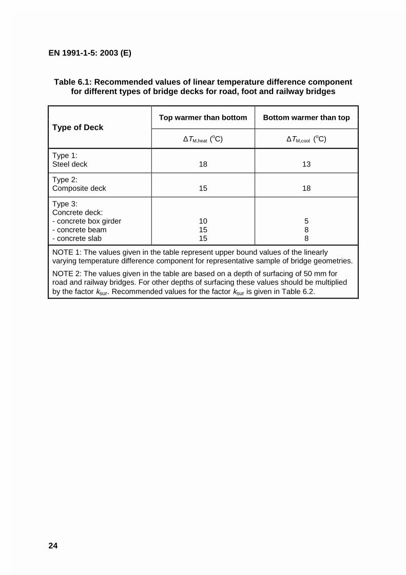
EN 1991-1-5: 2003 (E)
24
Table 6.1: Recommended values of linear temperature difference componentfor different types of bridge decks for road, foot and railway bridges
Top warmer than bottom Bottom warmer than topType of Deck
∆TM,heat (oC) ∆TM,cool (
oC)
Type 1:Steel deck 18 13
Type 2:Composite deck 15 18
Type 3:Concrete deck:- concrete box girder- concrete beam- concrete slab
101515
588
NOTE 1: The values given in the table represent upper bound values of the linearlyvarying temperature difference component for representative sample of bridge geometries.
NOTE 2: The values given in the table are based on a depth of surfacing of 50 mm forroad and railway bridges. For other depths of surfacing these values should be multipliedby the factor ksur. Recommended values for the factor ksur is given in Table 6.2.
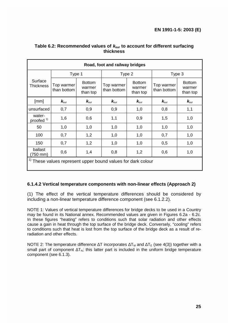
EN 1991-1-5: 2003 (E)
25
Table 6.2: Recommended values of ksur to account for different surfacingthickness
Road, foot and railway bridges
Type 1 Type 2 Type 3
SurfaceThickness Top warmer
than bottom
Bottomwarmerthan top
Top warmerthan bottom
Bottomwarmerthan top
Top warmerthan bottom
Bottomwarmerthan top
[mm] ksur ksur ksur ksur ksur ksur
unsurfaced 0,7 0,9 0,9 1,0 0,8 1,1
water-proofed 1) 1,6 0,6 1,1 0,9 1,5 1,0
50 1,0 1,0 1,0 1,0 1,0 1,0
100 0,7 1,2 1,0 1,0 0,7 1,0
150 0,7 1,2 1,0 1,0 0,5 1,0
ballast(750 mm) 0,6 1,4 0,8 1,2 0,6 1,0
1) These values represent upper bound values for dark colour
6.1.4.2 Vertical temperature components with non-linear effects (Approach 2)
(1) The effect of the vertical temperature differences should be considered byincluding a non-linear temperature difference component (see 6.1.2.2).
NOTE 1: Values of vertical temperature differences for bridge decks to be used in a Countrymay be found in its National annex. Recommended values are given in Figures 6.2a - 6.2c.In these figures “heating” refers to conditions such that solar radiation and other effectscause a gain in heat through the top surface of the bridge deck. Conversely, “cooling” refersto conditions such that heat is lost from the top surface of the bridge deck as a result of re-radiation and other effects.
NOTE 2: The temperature difference ∆T incorporates ∆TM and ∆TE (see 4(3)) together with asmall part of component ∆TN; this latter part is included in the uniform bridge temperaturecomponent (see 6.1.3).
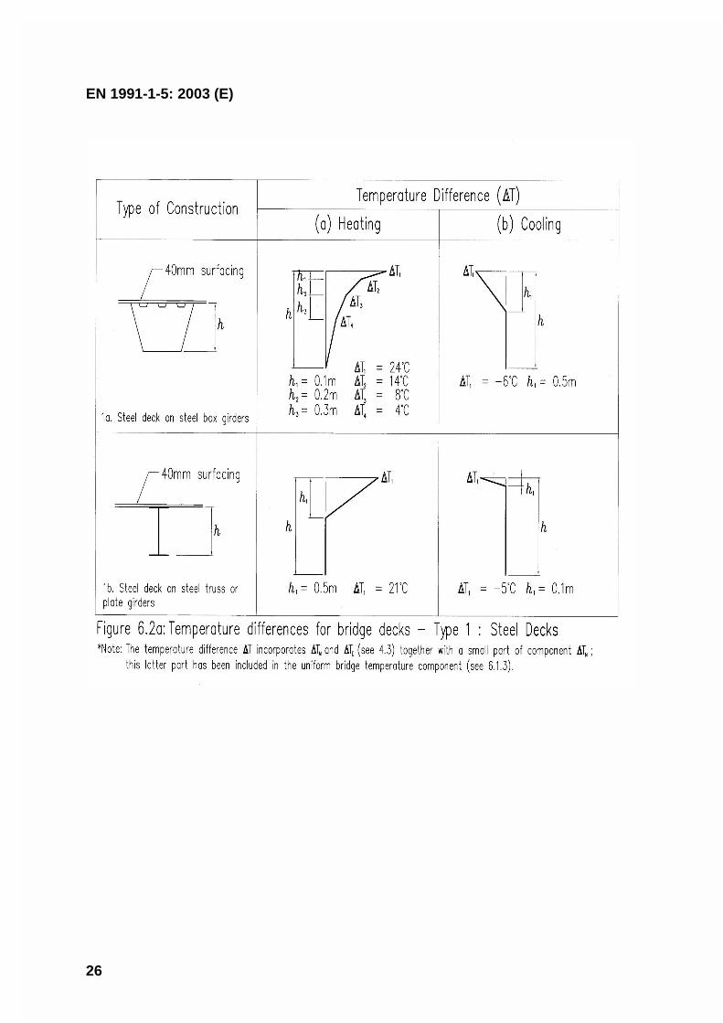
EN 1991-1-5: 2003 (E)
26
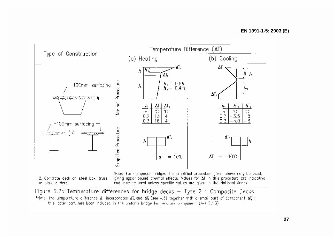
EN 1991-1-5: 2003 (E)
27
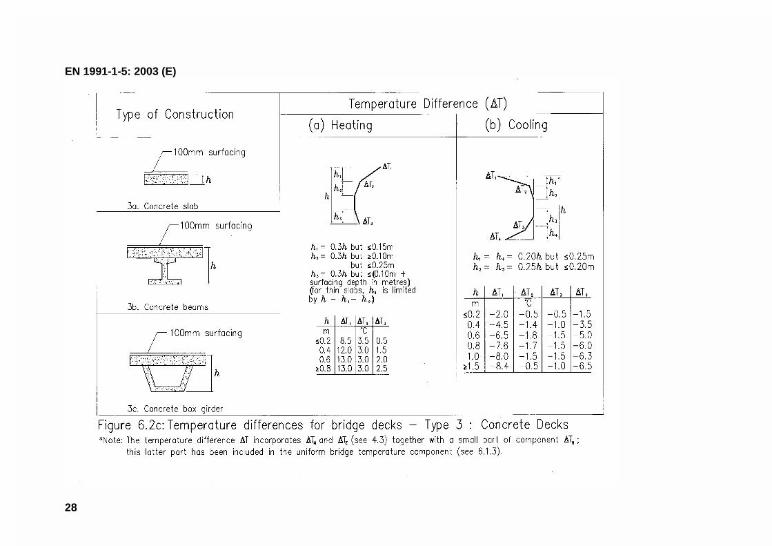
EN 1991-1-5: 2003 (E)
28
EN 1991-1-5: 2003 (E)
29
6.1.4.3 Horizontal components
(1) In general, the temperature difference component need only be considered in thevertical direction. In particular cases however (for example when the orientation orconfiguration of the bridge results in one side being more highly exposed to sunlightthan the other side), a horizontal temperature difference component should beconsidered.
NOTE: The National annex may specify numerical values for the temperature difference. Ifno other information is available and no indications of higher values exist, 5oC may berecommended as a linear temperature difference between the outer edges of the bridgeindependent of the width of the bridge.
6.1.4.4 Temperature difference components within walls of concrete boxgirders
(1) Care should be exercised in the design of large concrete box girder bridgeswhere significant temperature differences can occur between the inner and outer webwalls of such structures.
NOTE: The National annex may specify numerical values for the temperature difference. Therecommended value for a linear temperature difference is 150C.
6.1.5 Simultaneity of uniform and temperature difference components
(1) If it is necessary to take into account both the temperature difference ∆TM,heat (or∆TM,cool) and the maximum range of uniform bridge temperature component ∆TN,exp
(or ∆TN,con) assuming simultaneity (e.g. in case of frame structures) the followingexpression may be used (which should be interpreted as load combinations):
∆TM,heat (or ∆TM,cool) + ωN ∆TN,exp (or ∆TN,con) (6.3)or
ωM ∆TM,heat (or ∆TM,cool) + ∆TN,exp (or ∆TN,con) (6.4)
where the most adverse effect should be chosen.
NOTE 1: The National annex may specify numerical values of ωN and ωM. If no otherinformation is available, the recommended values for ωN and ωM are:
ωN = 0,35
ωM = 0,75.
NOTE 2: Where both linear and non-linear vertical temperature differences are used (see6.1.4.2) ∆TM should be replaced by ∆T which includes ∆TM and ∆TE .
EN 1991-1-5: 2003 (E)
30
6.1.6 Differences in the uniform temperature component between differentstructural elements
(1) In structures where differences in the uniform temperature component betweendifferent element types may cause adverse load effects, these effects should betaken into account.
NOTE: The National annex may give values for the differences in the uniform temperaturecomponent. Recommended values are:
– 15oC between main structural elements (e.g. tie and arch); and
– 10oC and 20oC for light and dark colour respectively between suspension/staycables and deck (or tower).
(2) These effects should be considered in addition to the effects resulting from auniform temperature component in all elements, determined from 6.1.3.
6.2 Bridge Piers
6.2.1 Consideration of thermal actions
(1)P Temperature differences between the outer faces of bridge piers, hollow orsolid, shall be considered in the design.
NOTE: The design procedure to be used in a Country may be found in its National annex. Ifno procedure is given an equivalent linear temperature difference may be assumed.
(2) Overall temperature effects of piers should be considered, when these can lead torestraining forces or movements in the surrounding structures.
6.2.2 Temperature differences
(1) For concrete piers (hollow or solid), the linear temperature differences betweenopposite outer faces should be taken into account.
NOTE: The National annex may specify values for linear temperature differences. In theabsence of detailed information the recommended value is 5oC.
(2) For walls the linear temperature differences between the inner and outer facesshould be taken into account.
NOTE 1: The National annex may specify values for linear temperature differences. In theabsence of detailed information the recommended value is 15oC.
NOTE 2: When considering temperature differences for metal columns specialist advice mayneed to be obtained.
EN 1991-1-5: 2003 (E)
31
Section 7 Temperature changes in industrial chimneys, pipelines,silos, tanks and cooling towers
7.1 General
(1)P Structures which are in contact with gas flow, liquids or material with differenttemperatures (e.g. industrial chimneys, pipelines, silos, tanks and cooling towers)shall be designed where relevant for the following conditions:
– thermal actions from climatic effects due to the variation of shade air temperatureand solar radiation,
– temperature distribution for normal and abnormal process conditions,
– effects arising from interaction between the structure and its contents duringthermal changes (e.g. shrinkage of the structure against stiff solid contents orexpansion of solid contents during heating or cooling).
NOTE 1: Values of the operating process temperature may be obtained from the particularproject.
NOTE 2: For the operating process temperatures of chimneys see EN 13084-1.
NOTE 3: Containment structures may be subjected to thermally induced changes in shapearising from heating/cooling effects of either the contents or their surrounding externalenvironment.
NOTE 4: No further guidance on the effect of shrinkage against stiff solid contents is given inthis standard. See EN 1991-4 for this effect in silos.
7.2 Temperature components
7.2.1 Shade air temperature
(1)P Values of minimum and maximum shade air temperatures for the site locationshall be obtained, e.g. from national maps of isotherms.
NOTE: Information (e.g. maps of isotherms) on minimum and maximum shade airtemperatures to be used in a Country may be found in its National annex.
(2) These shade air temperatures should be appropriate to mean sea level in opencountry with an annual probability of being exceeded of 0,02. annex A includesadjustments for other values of probabilities, height above sea level and localconditions e.g. frost pockets.
(3) For circumstances where an annual probability of being exceeded of 0,02 isdeemed inappropriate, e.g. during execution (see EN1991-1-6 “Actions during
EN 1991-1-5: 2003 (E)
32
execution”), the values of minimum (or maximum) shade air temperature should bemodified in accordance with annex A.
7.2.2 Flue gas, heated liquids and heated materials temperature
(1) Values of maximum and minimum flue gas, liquids and materials with differenttemperatures should be specified for the particular project.
7.2.3 Element temperature
(1) The derivation of values of element temperature will depend on the materialconfiguration, orientation and location of the element and will be a function of themaximum and minimum shade air temperature, the external solar radiation, and theinternal operating temperature.
NOTE: General rules for the determination of temperature profiles are given in annex D. Seealso 7.5.
7.3 Consideration of temperature components
(1)P Both the uniform temperature component of the temperature distribution (seeFigure 4.1 (a)) and the linearly varying temperature difference component (seeFigure 4.1 (b)) shall be considered for each layer.
(2)P The effect of solar radiation shall be considered in the design.
(3) This effect may be approximated by a step temperature distribution round thestructure’s circumference.
(4)P The uniform temperature component and the linearly varying temperaturedifference component due to process temperature shall be considered for each layer.
7.4 Determination of temperature components
(1)P The uniform and linearly varying temperature components shall be determinedtaking into account climatic effects and operating conditions.
(2) If specific information on how the element temperature can be correlated with thesolar radiation and shade air temperature is available in order to provide values ofelement temperature, such information should be used to provide design values.
(3)P Values of the uniform temperature component from heated gas flow, liquids andheated materials shall be taken from the project specification. As far as chimneys areconcerned these values shall be obtained from EN 13084-1.
(4)P The linearly varying temperature difference component in the wall or its layersshall be taken as arising from the difference between the minimum (or maximum)
EN 1991-1-5: 2003 (E)
33
shade air temperature on the outer face and the value of the liquid or gastemperature on the inner face, taking into account insulation effects.
NOTE: Temperature profiles may be determined using annex D.
7.5 Values of temperature components (indicative values)
(1) In the absence of any specific information on characteristic values of the elementtemperature, the following indicative values may be used.
NOTE: These values may be checked against any available data to ensure that they arelikely to be upper bound values, for the location and the type of element under consideration.
(2) Values of the maximum and minimum uniform temperature component should betaken as those of the maximum and minimum shade air temperature (see 7.2.1).
(3) For concrete pipelines the linear temperature difference component between theinner and outer faces of the wall should be considered.
NOTE 1: The National annex may specify the values for the linear temperature differencecomponent. The recommended value is 15oC.
NOTE 2: For chimneys see EN 13084-1.
(4) For concrete pipelines a stepped temperature component round thecircumference (causing both overall and local thermal effects) should be consideredon the basis that one quadrant of its circumference has a mean temperature higherthan that of the remainder of the circumference.
NOTE: The value of the difference of temperature may be given in the National annex. Therecommended value is 15oC.
(5) When considering steel pipelines, the linear temperature difference componentand stepped temperature component round the structure’s circumference should becalculated taking into account the operating conditions as set down in the particularproject.
NOTE: The rules for steel chimneys are given in EN 13084-1.
7.6 Simultaneity of temperature components
(1) When considering thermal actions due to climatic effects only, the followingcomponents take account of simultaneity:
a) uniform temperature component (see 7.5 (2) and Figure 7.1 (a));
b) stepped temperature component (see 7.5 (4) and Figure 7.1 (b));
EN 1991-1-5: 2003 (E)
34
c) the linear temperature difference component between the inner and the outerfaces of the wall (see 7.5 (3) and Figure 7.1 (c)).
(2) When considering a combination of thermal actions due to climatic effects withthose due to process effects (heated gas flow, liquids or heated materials) thefollowing components should be combined:
– uniform temperature component (see 7.4 (3));
– linear temperature difference component (see 7.4 (4));
– stepped component (see 7.5 (4)).
(3) The stepped temperature component should be considered to act simultaneouslywith wind.
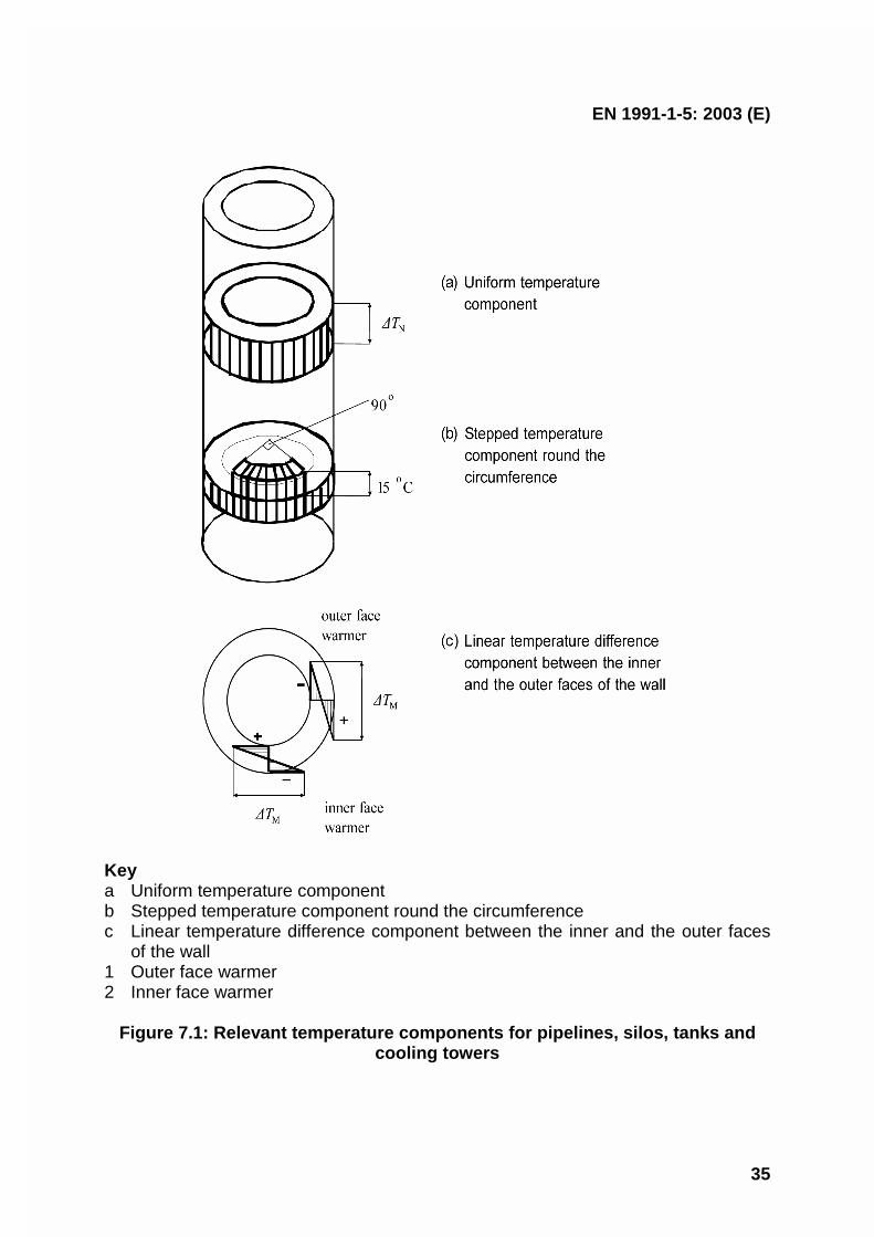
EN 1991-1-5: 2003 (E)
35
Keya Uniform temperature componentb Stepped temperature component round the circumferencec Linear temperature difference component between the inner and the outer faces
of the wall1 Outer face warmer2 Inner face warmer
Figure 7.1: Relevant temperature components for pipelines, silos, tanks andcooling towers
EN 1991-1-5: 2003 (E)
36
Annex A(Normative)
Isotherms of national minimum and maximum shade airtemperatures
A.1 General
(1) The values of both annual minimum and annual maximum shade air temperaturerepresent values with an annual probability of being exceeded of 0,02.
NOTE 1: Information (e.g. maps or tables of isotherms) on both annual minimum and annualmaximum shade air temperature to be used in a Country may be found in its National annex.
NOTE 2: These values may need to be adjusted for height above sea level. The adjustmentprocedure is given in the National annex. If no information is available the values of shade airtemperature may be adjusted for height above sea level by subtracting 0,5oC per 100 mheight for minimum shade air temperatures and 1,0oC per 100 m height for maximum shadeair temperatures.
(2) In locations where the minimum values diverge from the values given, such asfrost pockets and sheltered low lying areas where the minimum may be substantiallylower, or in large conurbations and coastal sites, where the minimum may be higherthan that indicated in the relevant figures, these divergences should be taken intoconsideration using local meteorological data.
(3) The initial temperature T0 should be taken as the temperature of a structuralelement at the relevant stage of its restraint (completion). If it is not predictable theaverage temperature during the construction period should be taken.
NOTE: The value of T0 may be specified in the National annex. If no information is availableT0 may be taken as 10oC.
A.2 Maximum and minimum shade air temperature values with an annualprobability of being exceeded p other than 0,02
(1) If the value of maximum (or minimum) shade air temperature, Tmax,p (Tmin,p), isbased on an annual probability of being exceeded p other than 0,02, the ratioTmax,p/Tmax (Tmin,p/Tmin) may be determined from Figure A.1.
(2) In general Tmax,p (or Tmin,p) may be derived from the following expressions basedon a type I extreme value distribution:
- for maximum: Tmax,p = Tmax k1 - k2 ln [ - ln (1-p) ] (A.1)
- for minimum: Tmin,p = Tmin k3+ k4 ln [ - ln (1-p) ] (A.2)
EN 1991-1-5: 2003 (E)
37
where:
Tmax (Tmin) is the value of maximum (minimum) shade air temperature withan annual probability of being exceeded of 0,02;
k1 = (uc) / (uc) + 3,902 (A.3)
k2 = 1 / (uc) + 3,902 (A.4)
where:
u,c are the mode and scale parameters of annual maximum shade airtemperature distribution.
k3 = (uc) / (uc) - 3,902 (A.5)
k4 = 1 / (uc) - 3,902 (A.6)
The parameters u and c are dependent on the mean value m and the standarddeviation σ of type I extreme value distribution:
for maximum u = m - 0,57722 / cc = 1,2825 / σ (A.7)
for minimum u = m + 0,57722 / cc = 1,2825 / σ (A.8)
The ratios Tmax,p/Tmax and Tmin,p/Tmin respectively may then be taken from Figure A.1.
NOTE1: The National annex may specify the values of the coefficients k1, k2, k3 and k4 basedon the values of parameters u and c. If no other information is available the following valuesare recommended:
k1 = 0,781;
k2 = 0,056;
k3 = 0,393;
k4 = - 0,156.
NOTE 2: Expression (A.2) and Figure A.1 can only be used if Tmin is negative.

EN 1991-1-5: 2003 (E)
38
Figure A.1: Ratios Tmax,p / Tmax and Tmin,p / Tmin
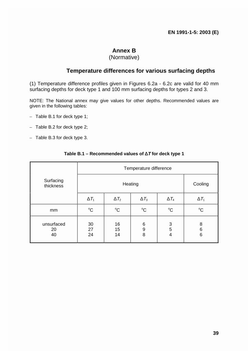
EN 1991-1-5: 2003 (E)
39
Annex B(Normative)
Temperature differences for various surfacing depths
(1) Temperature difference profiles given in Figures 6.2a - 6.2c are valid for 40 mmsurfacing depths for deck type 1 and 100 mm surfacing depths for types 2 and 3.
NOTE: The National annex may give values for other depths. Recommended values aregiven in the following tables:
– Table B.1 for deck type 1;
– Table B.2 for deck type 2;
– Table B.3 for deck type 3.
Table B.1 – Recommended values of ∆T for deck type 1
Temperature difference
Heating CoolingSurfacingthickness
∆T1 ∆T2 ∆T3 ∆T4 ∆T1
mm oC oC oC oC oC
unsurfaced2040
302724
161514
698
354
866
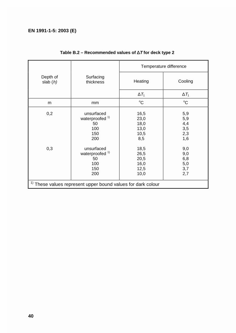
EN 1991-1-5: 2003 (E)
40
Table B.2 – Recommended values of ∆T for deck type 2
Temperature difference
Heating CoolingDepth ofslab (h)
Surfacingthickness
∆T1 ∆T1
m mm oC oC
0,2
0,3
unsurfacedwaterproofed 1)
50100150200
unsurfacedwaterproofed 1)
50100150200
16,523,018,013,010,58,5
18,526,520,516,012,510,0
5,95,94,43,52,31,6
9,09,06,85,03,72,7
1) These values represent upper bound values for dark colour
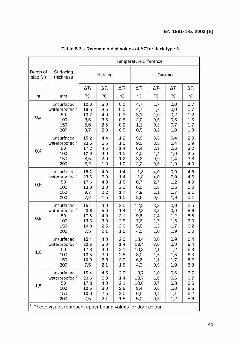
EN 1991-1-5: 2003 (E)
41
Table B.3 – Recommended values of ∆T for deck type 3
Temperature difference
Heating CoolingDepth ofslab (h)
Surfacingthickness
∆T1 ∆T2 ∆T3 ∆T1 ∆T2 ∆T3 ∆T4
m mm oC oC oC oC oC oC oC
0,2
unsurfacedwaterproofed 1)
50100150200
12,019,513,28,55,63,7
5,08,54,93,52,52,0
0,10,00,30,50,20,5
4,74,73,12,01,10,5
1,71,71,00,50,30,2
0,00,00,20,50,71,0
0,70,71,21,51,71,8
0,4
unsurfacedwaterproofed 1)
50100150200
15,223,617,212,08,56,2
4,46,54,63,02,01,3
1,21,01,41,51,21,0
9,09,06,44,53,22,2
3,53,52,31,40,90,5
0,40,40,61,01,41,9
2,92,93,23,53,84,0
0,6
unsurfacedwaterproofed 1)
50100150200
15,223,617,613,09,77,2
4,06,04,03,02,21,5
1,41,41,82,01,71,5
11,811,88,76,54,93,6
4,04,02,71,81,10,6
0,90,91,21,51,71,9
4,64,64,95,05,15,1
0,8
unsurfacedwaterproofed 1)
50100150200
15,423,617,813,510,07,5
4,05,04,03,02,52,1
2,01,42,12,52,01,5
12,812,89,87,65,84,5
3,33,32,41,71,31,0
0,90,91,21,51,71,9
5,65,65,86,06,26,0
1,0
unsurfacedwaterproofed 1)
50100150200
15,423,617,813,510,07,5
4,05,04,03,02,52,1
2,01,42,12,52,01,5
13,413,410,38,06,24,3
3,03,02,11,51,10,9
0,90,91,21,51,71,9
6,46,46,36,36,25,8
1,5
unsurfacedwaterproofed 1)
50100150200
15,423,617,813,510,07,5
4,55,04,03,02,52,1
2,01,42,12,52,01,5
13,713,710,68,46,55,0
1,01,00,70,50,40,3
0,60,60,81,01,11,2
6,76,76,66,56,25,6
1) These values represent upper bound values for dark colour

EN 1991-1-5: 2003 (E)
42
Annex C(Informative)
Coefficients of linear expansion
(1) For the determination of action effects due to temperature components, Table C.1gives values for the coefficient of linear expansion for a selection of commonly usedmaterials.
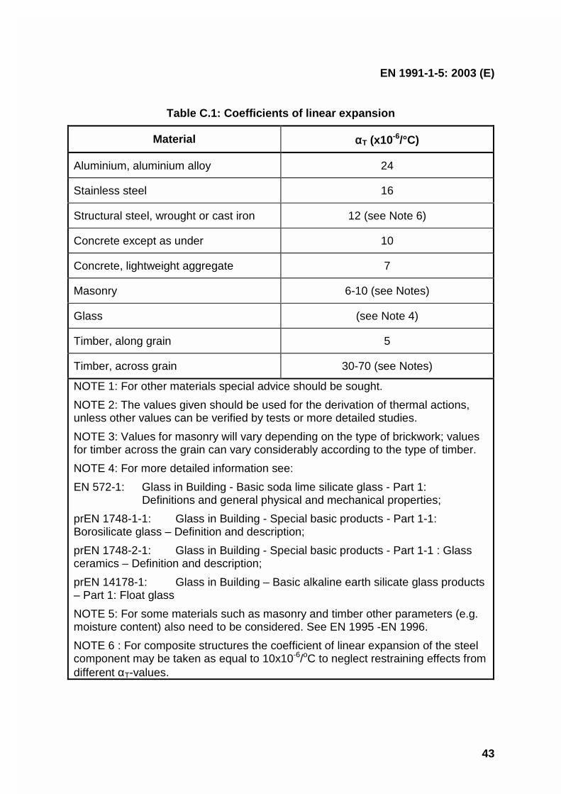
EN 1991-1-5: 2003 (E)
43
Table C.1: Coefficients of linear expansion
Material αT (x10-6/°C)
Aluminium, aluminium alloy 24
Stainless steel 16
Structural steel, wrought or cast iron 12 (see Note 6)
Concrete except as under 10
Concrete, lightweight aggregate 7
Masonry 6-10 (see Notes)
Glass (see Note 4)
Timber, along grain 5
Timber, across grain 30-70 (see Notes)
NOTE 1: For other materials special advice should be sought.
NOTE 2: The values given should be used for the derivation of thermal actions,unless other values can be verified by tests or more detailed studies.
NOTE 3: Values for masonry will vary depending on the type of brickwork; valuesfor timber across the grain can vary considerably according to the type of timber.
NOTE 4: For more detailed information see:
EN 572-1: Glass in Building - Basic soda lime silicate glass - Part 1:Definitions and general physical and mechanical properties;
prEN 1748-1-1: Glass in Building - Special basic products - Part 1-1:Borosilicate glass – Definition and description;
prEN 1748-2-1: Glass in Building - Special basic products - Part 1-1 : Glassceramics – Definition and description;
prEN 14178-1: Glass in Building – Basic alkaline earth silicate glass products– Part 1: Float glass
NOTE 5: For some materials such as masonry and timber other parameters (e.g.moisture content) also need to be considered. See EN 1995 -EN 1996.
NOTE 6 : For composite structures the coefficient of linear expansion of the steelcomponent may be taken as equal to 10x10-6/oC to neglect restraining effects fromdifferent αT-values.

EN 1991-1-5: 2003 (E)
44
Annex D(Informative)
Temperature profiles in buildings and other construction works
(1) Temperature profiles may be determined using the thermal transmission theory.In the case of a simple sandwich element (e.g. slab, wall, shell) under theassumption that local thermal bridges do not exist a temperature T(x) at a distance xfrom the inner surface of the cross section may be determined assuming steadythermal state as
)()(
)( outintot
in TTR
xRTxT −−= (D.1)
where:
Tin is the air temperature of the inner environmentTout is the temperature of the outer environmentRtot is the total thermal resistance of the element including resistance of
both surfacesR(x) is the thermal resistance at the inner surface and of the element from
the inner surface up to the point x (see Figure D.1).
(2) The resistance values Rtot, and R(x) [m2K/W] may be determined using thecoefficient of heat transfer and coefficients of thermal conductivity given in EN ISO6946 (1996) and EN ISO 13370 (1998):
outintot Rh
RRi i
i ++= ∑ λ(D.2)
where:
Rin is the thermal resistance at the inner surface [m2K/W],Rout is the thermal resistance at the outer surface [m2K/W],
λi is the thermal conductivity and hi [m] is the thickness of the layer i,[W/(mK)]
∑+=i i
ihRxR
λin)( (D.3)
where layers (or part of a layer) from the inner surface up to point x (see Figure D.1)are considered only.
NOTE: In buildings the thermal resistance Rin = 0,10 to 0,17 [m2K/W] (depending on the
orientation of the heat flow), and Rout
= 0,04 (for all orientations). The thermal conductivity λi
for concrete (of volume weight from 21 to 25 kN/m3) varies from λi = 1,16 to 1,71 [W/(mK)].
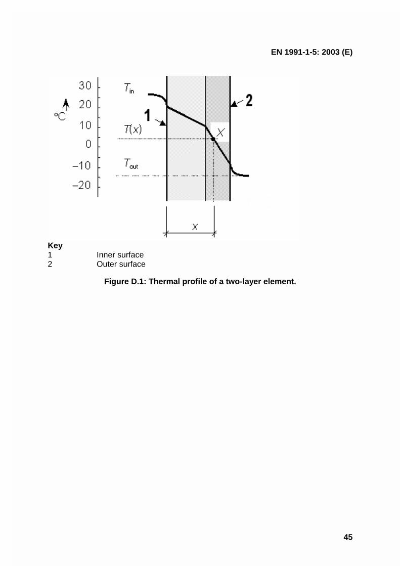
EN 1991-1-5: 2003 (E)
45
Key1 Inner surface2 Outer surface
Figure D.1: Thermal profile of a two-layer element.

EN 1991-1-5: 2003 (E)
46
Bibliography
EN 1991-2 Eurocode 1: Actions on structures - Part 2: Traffic loads on bridges
EN 1991-4 Eurocode 1: Basis of design and actions on structures - Part 4: Silos andtanks

EUROPEAN STANDARD
NORME EUROPÉENNE
EUROPÄISCHE NORM
FINAL DRAFTprEN 1991-1-6
September 2004
ICS 91.010.30 Will supersede ENV 1991-2-6:1997
English version
Eurocode 1 - Actions on structures Part 1-6: General actions -Actions during execution
Eurocode 1 - Actions sur les structures - Partie 1-6 :Actions générales - Actions en cours d'exécution
Eurocode 1 - Einwirkungen auf Tragwerke Teil 1-6:Allgemeine Einwirkungen - Einwirkungen während der
Bauausführung
This draft European Standard is submitted to CEN members for formal vote. It has been drawn up by the Technical Committee CEN/TC250.
If this draft becomes a European Standard, CEN members are bound to comply with the CEN/CENELEC Internal Regulations whichstipulate the conditions for giving this European Standard the status of a national standard without any alteration.
This draft European Standard was established by CEN in three official versions (English, French, German). A version in any other languagemade by translation under the responsibility of a CEN member into its own language and notified to the Management Centre has the samestatus as the official versions.
CEN members are the national standards bodies of Austria, Belgium, Cyprus, Czech Republic, Denmark, Estonia, Finland, France,Germany, Greece, Hungary, Iceland, Ireland, Italy, Latvia, Lithuania, Luxembourg, Malta, Netherlands, Norway, Poland, Portugal, Slovakia,Slovenia, Spain, Sweden, Switzerland and United Kingdom.
Warning : This document is not a European Standard. It is distributed for review and comments. It is subject to change without notice andshall not be referred to as a European Standard.
EUROPEAN COMMITTEE FOR STANDARDIZATIONC OM ITÉ EUR OP ÉEN DE NOR M ALIS AT IONEUROPÄISCHES KOMITEE FÜR NORMUNG
Management Centre: rue de Stassart, 36 B-1050 Brussels
© 2004 CEN All rights of exploitation in any form and by any means reservedworldwide for CEN national Members.
Ref. No. prEN 1991-1-6:2004: E
page 2Draft prEN 1991-1-6:2003
Contents Page
FOREWORD ............................................................................................................................................................................... 3
BACKGROUND OF THE EUROCODE PROGRAMME ........................................................................................................................ 3STATUS AND FIELD OF APPLICATION OF EUROCODES ................................................................................................................. 4NATIONAL STANDARDS IMPLEMENTING EUROCODES ................................................................................................................ 4LINKS BETWEEN EUROCODES AND HARMONISED TECHNICAL SPECIFICATIONS (ENS AND ETAS) FOR PRODUCTS ..................... 5ADDITIONAL INFORMATION SPECIFIC TO EN 1991-1-6.............................................................................................................. 5NATIONAL ANNEX ...................................................................................................................................................................... 5
SECTION 1 GENERAL........................................................................................................................................................ 7
1.1 SCOPE............................................................................................................................................................................. 71.2 NORMATIVE REFERENCES............................................................................................................................................... 71.3 ASSUMPTIONS ...................................................................................................................................................................... 81.4 DISTINCTION BETWEEN PRINCIPLES AND APPLICATION RULES.............................................................................................. 81.5 TERMS AND DEFINITIONS...................................................................................................................................................... 81.6 SYMBOLS.............................................................................................................................................................................. 8
SECTION 2 CLASSIFICATION OF ACTIONS .............................................................................................................. 11
SECTION 3 DESIGN SITUATIONS AND LIMIT STATES ........................................................................................... 13
3.1 GENERAL – IDENTIFICATION OF DESIGN SITUATIONS.......................................................................................................... 133.2 ULTIMATE LIMIT STATES .................................................................................................................................................... 143.3 SERVICEABILITY LIMIT STATES........................................................................................................................................... 15
SECTION 4 REPRESENTATION OF ACTIONS ........................................................................................................... 16
4.1 GENERAL............................................................................................................................................................................ 164.2 ACTIONS ON STRUCTURAL AND NON-STRUCTURAL MEMBERS DURING HANDLING ............................................................. 164.3 GEOTECHNICAL ACTIONS ................................................................................................................................................... 174.4 ACTIONS DUE TO PRESTRESSING......................................................................................................................................... 174.5 PREDEFORMATIONS............................................................................................................................................................ 174.6 TEMPERATURE, SHRINKAGE, HYDRATION EFFECTS ............................................................................................................ 174.7 WIND ACTIONS ................................................................................................................................................................... 184.8 SNOW LOADS...................................................................................................................................................................... 184.9 ACTIONS CAUSED BY WATER.............................................................................................................................................. 184.10 ACTIONS DUE TO ATMOSPHERIC ICING.............................................................................................................................. 204.11 CONSTRUCTION LOADS..................................................................................................................................................... 204.12 ACCIDENTAL ACTIONS...................................................................................................................................................... 234.13 SEISMIC ACTIONS ............................................................................................................................................................. 24
ANNEX A1 (NORMATIVE) ..................................................................................................................................................... 25
SUPPLEMENTARY RULES FOR BUILDINGS .................................................................................................................. 25
A1.1 ULTIMATE LIMIT STATES ................................................................................................................................................. 25A1.2 SERVICEABILITY LIMIT STATES........................................................................................................................................ 25A1.3 HORIZONTAL ACTIONS..................................................................................................................................................... 25
ANNEX A2 (NORMATIVE) ..................................................................................................................................................... 26
SUPPLEMENTARY RULES FOR BRIDGES ...................................................................................................................... 26
A2.1 ULTIMATE LIMIT STATES ................................................................................................................................................. 26A2.2 SERVICEABILITY LIMIT STATES........................................................................................................................................ 26A2.3 DESIGN VALUES OF DEFLECTIONS.................................................................................................................................... 26A2.4 SNOW LOADS ................................................................................................................................................................... 26A2.5 CONSTRUCTION LOADS.................................................................................................................................................... 27
ANNEX B (INFORMATIVE) ACTIONS ON STRUCTURES DURING ALTERATION, RECONSTRUCTION ORDEMOLITION ............................................................................................................................................................................ 28
BIBLIOGRAPHY……………………………………………………………………………………………………………….27

page 3Draft prEN 1991-1-6:2003
Foreword
This European document (EN 1991-1-6), has been prepared by Technical Committee CEN/TC250 “StructuralEurocodes”, the Secretariat of which is held by BSI.
CEN/TC250 is responsible for all Structural Eurocodes.
This document will supersede ENV 1991-2-6 : 1996.
Annexes A1 and A2 are normative and Annex B is informative. This Standard includes a Bibliography.
According to the CEN/CENELEC Internal Regulations, the national standards organizations of the following coun-tries are bound to implement this European Standard: Austria, Belgium, Czech Republic, Denmark, Finland,France, Germany, Greece, Hungary, Iceland, Ireland, Italy, Luxembourg, Malta, Netherlands, Norway, Portugal,Slovakia, Spain, Sweden, Switzerland and the United Kingdom2.
Background of the Eurocode programme
In 1975, the Commission of the European Community decided on an action programme in the field of construction,based on article 95 of the Treaty. The objective of the programme was the elimination of technical obstacles totrade and the harmonisation of technical specifications.
Within this action programme, the Commission took the initiative to establish a set of harmonised technical rules forthe design of construction works which, in a first stage, would serve as an alternative to the national rules in force inthe Member States and, ultimately, would replace them.
For fifteen years, the Commission, with the help of a Steering Committee with Representatives of Member States,conducted the development of the Eurocodes programme, which led to the first generation of European codes inthe 1980s.
In 1989, the Commission and the Member States of the EU and EFTA decided, on the basis of an agreement3 be-tween the Commission and CEN, to transfer the preparation and the publication of the Eurocodes to CEN through aseries of Mandates, in order to provide them with a future status of European Standard (EN). This links de facto theEurocodes with the provisions of all the Council’s Directives and/or Commission’s Decisions dealing with Europeanstandards (e.g. the Council Directive 89/106/EEC on construction products – CPD - and Council Directives93/37/EEC, 92/50/EEC and 89/440/EEC on public works and services and equivalent EFTA Directives initiated inpursuit of setting up the internal market).
The Structural Eurocode programme comprises the following standards generally consisting of a number of Parts:
EN 1990 Eurocode Basis of structural design
EN 1991 Eurocode 1: Actions on structures
EN 1992 Eurocode 2: Design of concrete structures
EN 1993 Eurocode 3: Design of steel structures
EN 1994 Eurocode 4: Design of composite steel and concrete structures
EN 1995 Eurocode 5: Design of timber structures
EN 1996 Eurocode 6: Design of masonry structures
2 To be augmented as appropriate3 Agreement between the Commission of the European Communities and the European Committee for Standardisation (CEN) concerning the
work on EUROCODES for the design of building and civil engineering works (BC/CEN/03/89).

page 4Draft prEN 1991-1-6:2003
EN 1997 Eurocode 7: Geotechnical design
EN 1998 Eurocode 8: Design of structures for earthquake resistance
EN 1999 Eurocode 9: Design of aluminium structuresEurocode standards recognise the responsibility of regulatory authorities in each Member State and have safe-guarded their right to determine values related to regulatory safety matters at national level where these continue tovary from State to State.
Status and field of application of Eurocodes
The Member States of the EU and EFTA recognise that Eurocodes serve as reference documents for the followingpurposes :
– as a means to prove compliance of building and civil engineering works with the essential requirements of Coun-cil Directive 89/106/EEC, particularly Essential Requirement N°1 – Mechanical resistance and stability – andEssential Requirement N°2 – Safety in case of fire ;
– as a basis for specifying contracts for construction works and related engineering services ;
– as a framework for drawing up harmonised technical specifications for construction products (ENs and ETAs)
The Eurocodes, as far as they concern the construction works themselves, have a direct relationship with the Inter-pretative Documents4 referred to in Article 12 of the CPD, although they are of a different nature from harmonisedproduct standards5. Therefore, technical aspects arising from the Eurocodes work need to be adequately consid-ered by CEN Technical Committees and/or EOTA Working Groups working on product standards with a view toachieving a full compatibility of these technical specifications with the Eurocodes.
The Eurocode standards provide common structural design rules for everyday use for the design of whole struc-tures and component products of both a traditional and an innovative nature. Unusual forms of construction or de-sign conditions are not specifically covered and additional expert consideration will be required by the designer insuch cases.
National Standards implementing Eurocodes
The National Standards implementing Eurocodes will comprise the full text of the Eurocode (including any an-nexes), as published by CEN, which may be preceded by a National title page and National foreword, and may befollowed by a National annex.
The National Annex may only contain information on those parameters which are left open in the Eurocode for na-tional choice, known as Nationally Determined Parameters, to be used for the design of buildings and civil engi-neering works to be constructed in the country concerned, i.e. :
–values and/or classes where alternatives are given in the Eurocode,
–values to be used where a symbol only is given in the Eurocode,
–country specific data (geographical, climatic, etc), e.g. snow map,
–the procedure to be used where alternative procedures are given in the Eurocode.
4 According to Art. 3.3 of the CPD, the essential requirements (ERs) shall be given concrete form in interpretative documents for the creation of
the necessary links between the essential requirements and the mandates for hENs and ETAGs/ETAs.5 According to Art. 12 of the CPD the interpretative documents shall :
a)give concrete form to the essential requirements by harmonising the terminology and the technical bases and indicating classes or levels foreach requirement where necessary ;
b)indicate methods of correlating these classes or levels of requirement with the technical specifications, e.g. methods of calculation and ofproof, technical rules for project design, etc. ;
c)serve as a reference for the establishment of harmonised standards and guidelines for European technical approvals.The Eurocodes, de facto, play a similar role in the field of the ER 1 and a part of ER 2.

page 5Draft prEN 1991-1-6:2003
It may also contain:
–decisions on the application of informative annexes,
–references to non-contradictory complementary information to assist the user to apply the Eurocode.
Links between Eurocodes and harmonised technical specifications (ENs and ETAs) for products
There is a need for consistency between the harmonised technical specifications for construction products and thetechnical rules for works6. Furthermore, all the information accompanying the CE Marking of the construction prod-ucts which refer to Eurocodes shall clearly mention which Nationally Determined Parameters have been taken intoaccount.
Additional information specific to EN 1991-1-6
EN 1991-1-6 describes Principles and Application rules for the assessment of actions to be considered during exe-cution of buildings and civil engineering works, including the following aspects :
⎯ actions on structural and non-structural members during handling;⎯ geotechnical actions ;⎯ actions due to prestressing effects ;⎯ predeformations ;⎯ temperature, shrinkage, hydration effects ;⎯ wind actions ;⎯ snow loads ;⎯ actions caused by water ;⎯ actions due to atmospheric icing ;⎯ construction loads ;⎯ accidental actions ⎯ seismic actions;
EN 1991-1-6 is intended for use by:
⎯ clients (e.g. for the formulation of their specific requirements),⎯ designers and constructors,⎯ relevant authorities.
EN 1991-1-6 is intended to be used with EN 1990, the other Parts of EN 1991 and EN 1992 to EN 1999 for the de-sign of structures.
National annex
This Part of EN1991 gives alternative procedures, values and recommendations for classes with notes indicatingwhere national choices may have to be made. Therefore the National Standard implementing EN 1991-1-6 shouldhave a National Annex containing all Nationally Determined Parameters to be used for the design of buildings andcivil engineering works to be constructed in the relevant country.
National choice is allowed in EN 1991-1-6 through clauses:
Clause Item1.1(3) Design rules for auxiliary construction works2 (4) Positioning of construction loads classified as free3.1(1)P Design situation corresponding to storm conditions3.1(5) NOTE 1
NOTE 2
Return periods for the assessment of the characteristic values of variable actions during execu-tionMinimum wind speed during execution
3.1(7) Rules for the combination of snow loads and wind actions with construction loads3.1(8) NOTE 1 Rules concerning imperfections in the geometry of the structure 6 see Art.3.3 and Art.12 of the CPD, as well as clauses 4.2, 4.3.1, 4.3.2 and 5.2 of ID 1.
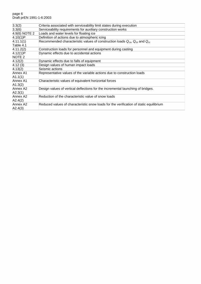
page 6Draft prEN 1991-1-6:2003
3.3(2) Criteria associated with serviceability limit states during execution3.3(6) Serviceability requirements for auxiliary construction works4.9(6) NOTE 2 Loads and water levels for floating ice4.10(1)P Definition of actions due to atmospheric icing4.11.1(1)Table 4.1
Recommended characteristic values of construction loads Qca, Qcb and Qcc
4.11.2(2) Construction loads for personnel and equipment during casting4.12(1)PNOTE 2
Dynamic effects due to accidental actions
4.12(2) Dynamic effects due to falls of equipment4.12 (3) Design values of human impact loads4.13(2) Seismic actionsAnnex A1A1.1(1)
Representative values of the variable actions due to construction loads
Annex A1A1.3(2)
Characteristic values of equivalent horizontal forces
Annex A2A2.3(1)
Design values of vertical deflections for the incremental launching of bridges.
Annex A2A2.4(2)
Reduction of the characteristic value of snow loads
Annex A2A2.4(3)
Reduced values of characteristic snow loads for the verification of static equilibrium

page 7Draft prEN 1991-1-6:2003
Section 1 General
1.1 Scope
(1) EN 1991-1-6 provides principles and general rules for the determination of actions which should be taken intoaccount during execution of buildings and civil engineering works.
NOTE 1 : This Part of EN 1991 may be used as guidance for the determination of actions to be taken into account for differ-ent types of construction works, including structural alterations such as refurbishment and/or partial or full demolition. Fur-ther guidance is given in Annexes A1 and A2.
NOTE 2 : Rules concerning the safety of people in and around the construction site are out of the scope of this Europeanstandard. Such rules may be defined for the individual project.
(2) The following subjects are dealt with in Part 1.6 of EN 1991.
Section 1 : General
Section 2 : Classification of actions
Section 3: Design situations and limit states
Section 4 : Representation of actions
Annex A1 : Supplementary rules for buildings (normative)
Annex A2 : Supplementary rules for bridges (normative)
Annex B : Actions on structures during alteration, reconstruction or demolition (informative)
(3) EN 1991-1-6 also gives rules for the determination of actions which may be used for the design of auxiliary con-struction works as defined in 1.5, needed for the execution of buildings and civil engineering works.
NOTE Design rules for auxiliary construction works may be defined in the National Annex or for the individual project. Guid-ance may be found in the relevant European standards. For example, design rules for formworks and falseworks are givenin EN 12812.
1.2 Normative references
This European standard incorporates by dated or undated reference provisions from other publications. Thesenormative references are cited at the appropriate places in the text and the publications are listed hereafter. Fordated references, subsequent amendments to, or revisions of, any of these publications apply to this Europeanstandard only when incorporated in it by amendment or revision. For undated references, the latest edition of thepublications referred to applies (including amendments).
NOTE The Eurocodes were published as European Prestandards. The following European Standards which are publishedor in preparation are cited in normative clauses or in NOTES to normative clauses.
EN 1990 Eurocode : Basis of structural design
EN 1991-1-1 Eurocode 1: Actions on structures Part 1-1: Densities, self-weight, imposed loads for buildings
EN 1991-1-2 Eurocode 1: Actions on structures Part 1-2: Fire actions
EN 1991-1-3 Eurocode 1: Actions on structures Part 1-3: General actions: Snow loads
EN 1991-1-4 Eurocode 1: Actions on structures Part 1-4: General actions: Wind actions

page 8Draft prEN 1991-1-6:2003
EN 1991-1-5 Eurocode 1: Actions on structures Part 1-5: General actions: Thermal actions
EN 1991-1-7 Eurocode 1: Actions on structures Part 1-7: Accidental actions
EN 1991-2 Eurocode 1: Actions on structures Part 2: Traffic loads on bridges
EN 1991-3 Eurocode 1: Actions on structures Part 3: Actions induced by cranes and machinery
EN 1991-4 Eurocode 1: Actions on structures Part 4: Silos and tanks
EN 1992 Eurocode 2: Design of concrete structures
EN 1993 Eurocode 3: Design of steel structures
EN 1994 Eurocode 4: Design of composite steel and concrete structures
EN 1995 Eurocode 5: Design of timber structures
EN 1996 Eurocode 6: Design of masonry structures
EN 1997 Eurocode 7: Geotechnical design
EN 1998 Eurocode 8: Design of structures for earthquake resistance
EN 1999 Eurocode 9: Design of aluminium structures
1.3 Assumptions
(1)P The general assumptions given in EN 1990, 1.3 apply.
1.4 Distinction between principles and application rules
(1)P The rules in EN 1990, 1.4 apply.
1.5 Terms and definitions
1.5.1 General
(1) The terms and definitions given in EN 1990, 1.5 apply.
1.5.2 Additional terms and definitions specific to this Standard
1.5.2.1auxiliary construction works any works associated with the construction processes that are not required after use when the related executionactivities are completed and they can be removed (e.g. falsework, scaffolding, propping systems, cofferdam, brac-ing, launching nose)
NOTE Completed structures for temporary use (e.g. a bridge for temporarily diverted traffic) are not regarded as auxiliaryconstruction works.
1.5.2.2construction load load that can be present due to execution activities, but is not present when the execution activities are completed.
1.6 Symbols
For the purpose of this European standard, the following symbols apply (see also EN 1990).

page 9Draft prEN 1991-1-6:2003
Latin upper case letters
Adeb area of obstruction (accumulation of debris)
Fdeb horizontal forces exerted by accumulation of debris
Fcb.k characteristic values of concentrated construction loads Qcb
Fhn nominal horizontal forces
Fwa horizontal forces due to currents on immersed obstacles
Qc construction loads (general symbol)
Qca construction loads due to working personnel, staff and visitors, possibly with handtools or other small siteequipment
Qcb construction loads due to storage of moveable items (e.g. building and construction materials, precastelements, and equipment)
Qcc construction loads due to non permanent equipment in position for use during execution, either static (e.g.formwork panels, scaffolding, falsework, machinery, containers) or during movement (e.g. travellingforms, launching girders and nose, counterweights)
Qcd construction loads due to moveable heavy machinery and equipment, usually wheeled or tracked (e.g.cranes, lifts, vehicles, lifttrucks, power installations, jacks, heavy control devices)
Qce construction loads from accumulation of waste materials (e.g. surplus construction materials, excavatedsoil or demolition materials)
Qcf Construction loads from parts of a structure in temporary states (under execution) before the final designactions take effect
QW wind actions
Qwa actions caused by water
Latin lower case letters
b width of an immersed object
cpe external wind pressure coefficients for free-standing walls
h water depth
k shape factor for an immersed object
p flowing water pressure, which may be current water
qca,k characteristic values of the uniformly distributed loads of construction loads Qca
qcb,k characteristic values of the uniformly distributed loads of construction loads Qcb

page 10Draft prEN 1991-1-6:2003
qcc,k characteristic values of the uniformly distributed loads representing construction loads Qcc
vw mean speed of water
Greek lower case letters
ρwa density of water
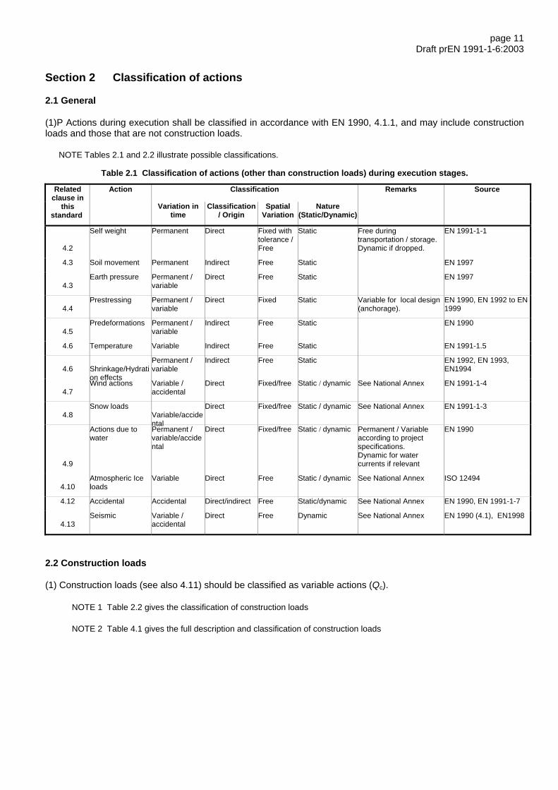
page 11Draft prEN 1991-1-6:2003
Section 2 Classification of actions
2.1 General
(1)P Actions during execution shall be classified in accordance with EN 1990, 4.1.1, and may include constructionloads and those that are not construction loads.
NOTE Tables 2.1 and 2.2 illustrate possible classifications.
Table 2.1 Classification of actions (other than construction loads) during execution stages.
Classification Remarks SourceRelatedclause in
thisstandard
Action
Variation intime
Classification/ Origin
SpatialVariation
Nature(Static/Dynamic)
4.2
Self weight Permanent Direct Fixed withtolerance /Free
Static Free duringtransportation / storage.Dynamic if dropped.
EN 1991-1-1
4.3 Soil movement Permanent Indirect Free Static EN 1997
4.3Earth pressure Permanent /
variableDirect Free Static EN 1997
4.4Prestressing Permanent /
variableDirect Fixed Static Variable for local design
(anchorage).EN 1990, EN 1992 to EN1999
4.5Predeformations Permanent /
variableIndirect Free Static EN 1990
4.6 Temperature Variable Indirect Free Static EN 1991-1.5
4.6 Shrinkage/Hydration effects
Permanent /variable
Indirect Free Static EN 1992, EN 1993,EN1994
4.7Wind actions Variable /
accidentalDirect Fixed/free Static / dynamic See National Annex EN 1991-1-4
4.8Snow loads
Variable/accidental
Direct Fixed/free Static / dynamic See National Annex EN 1991-1-3
4.9
Actions due towater
Permanent /variable/accidental
Direct Fixed/free Static / dynamic Permanent / Variableaccording to projectspecifications.Dynamic for watercurrents if relevant
EN 1990
4.10Atmospheric Iceloads
Variable Direct Free Static / dynamic See National Annex ISO 12494
4.12 Accidental Accidental Direct/indirect Free Static/dynamic See National Annex EN 1990, EN 1991-1-7
4.13Seismic Variable /
accidentalDirect Free Dynamic See National Annex EN 1990 (4.1), EN1998
2.2 Construction loads
(1) Construction loads (see also 4.11) should be classified as variable actions (Qc).
NOTE 1 Table 2.2 gives the classification of construction loads
NOTE 2 Table 4.1 gives the full description and classification of construction loads
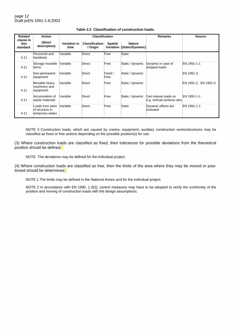
page 12Draft prEN 1991-1-6:2003
Table 2.2 Classification of construction loads.
Classification Remarks SourceRelatedclause in
thisstandard
Action
(Shortdescription)
Variation intime
Classification/ Origin
SpatialVariation
Nature(Static/Dynamic)
4.11Personnel andhandtools
Variable Direct Free Static
4.11Storage movableitems
Variable Direct Free Static / dynamic Dynamic in case ofdropped loads
EN 1991-1-1
4.11Non-permanentequipment
Variable Direct Fixed /Free
Static / dynamic EN 1991-3
4.11
Movable heavymachinery andequipment
Variable Direct Free Static / dynamic EN 1991-2, EN 1991-3
4.11Accumulation ofwaste materials
Variable Direct Free Static / dynamic Can impose loads one.g. vertical surfaces also
EN 1991-1-1
4.11
Loads from partsof structure intemporary states
Variable Direct Free Static Dynamic effects areexcluded
EN 1991-1-1
NOTE 3 Construction loads, which are caused by cranes, equipment, auxiliary construction works/structures may beclassified as fixed or free actions depending on the possible position(s) for use.
(3) Where construction loads are classified as fixed, then tolerances for possible deviations from the theoreticalposition should be defined.
NOTE The deviations may be defined for the individual project.
(4) Where construction loads are classified as free, then the limits of the area where they may be moved or posi-tioned should be determined.
NOTE 1 The limits may be defined in the National Annex and for the individual project.
NOTE 2 In accordance with EN 1990, 1.3(2), control measures may have to be adopted to verify the conformity of theposition and moving of construction loads with the design assumptions.

page 13Draft prEN 1991-1-6:2003
Section 3 Design situations and limit states
3.1 General – identification of design situations
(1)P Transient, accidental and seismic design situations shall be identified and taken into account as appropriatefor designs for execution.
NOTE For wind actions during storm conditions (e.g. cyclone, hurricane) the National Annex may select the design situa-tion to be used. The recommended design situation is the accidental design situation.
(2) Design situations should be selected as appropriate for the structure as a whole, the structural members, thepartially completed structure, and also for auxiliary construction works and equipment.
(3)P The selected design situations shall take into account the conditions that apply from stage to stage duringexecution in accordance with EN 1990, 3.2(3)P.
(4)P The selected design situations shall be in accordance with the execution processes anticipated in the design.Design situations shall take account of any (proposed) revisions to the execution processes.
(5) Any selected transient design situation should be associated with a nominal duration equal to or greater thanthe anticipated duration of the stage of execution under consideration. The design situations should take into ac-count the likelihood for any corresponding return periods of variable actions (e.g. climatic actions).
NOTE 1 The return periods for the assessment of characteristic values of variable actions during execution may be definedin the National Annex or for the individual project. Recommended return periods of climatic actions are given in Table 3.1,depending on the nominal duration of the relevant design situation.
Table 3.1 Recommended return periods for the assessment of the characteristic values of climatic actions
Duration Return period (years)≤ 3 days≤ 3 months (but > 3 days)≤ 1 year (but > 3 months)> 1 year
2 a
5 b
10 50
a A nominal duration of three days, to be chosen for short execution phases, corresponds to the extent in time of reli-able meteorological predictions for the location of the site. This choice may be kept for a slightly longer execution phaseif appropriate organisational measures are taken. The concept of mean return period is generally not appropriate forshort term duration.
b For a nominal duration of up to three months actions may be determined taking into account appropriate seasonal andshorter term meteorological climatic variations. For example, the flood magnitude of a river depends on the period of theyear under consideration.
NOTE 2 A minimum wind velocity during execution may be defined in the National Annex or for the individual project. Therecommended basic value for durations of up to 3 months is 20 m/s in accordance with EN 1991-1-4.
NOTE 3 Relationships between characteristic values and return period for climatic actions are given in the appropriate Partsof EN 1991.

page 14Draft prEN 1991-1-6:2003
(6) Where an execution stage design prescribes limiting climatic conditions, or weather window, the characteristicclimatic actions should be determined taking into account :
– duration of the execution stage,
– the reliability of meteorological predictions,
– time to organise protection measures.
(7) The rules for the combination of snow loads and wind actions with construction loads Qc (see 4.11.1) should bedefined.
NOTE : These rules may be defined in the National Annex or for the individual project.
(8) Imperfections in the geometry of the structure and of structural members should be defined for the selected de-sign situations during execution.
NOTE 1 These imperfections may be defined in the National Annex or for the individual project. See also Annex A2 and EN1990, 3.5 (3) and (7).
NOTE 2 For concrete structures, see also European Standards established by CEN/TC/229 ”Precast Concrete Products”.See EN 13670.
(9) Actions due to wind excitation (including aerodynamic effects due to passing vehicles, including trains) that aresusceptible to produce fatigue effects on structural members should be taken into account.
NOTE See EN 1991-1-4 and EN 1991-2.
(10) Where the structure or parts of it are subjected to accelerations that may give rise to dynamic or inertia effects,these effects should be taken into account.
NOTE Significant accelerations may be excluded where possible movements are strictly controlled by appropriate devices.
(11) Actions caused by water, including for example uplift due to groundwater, should be determined in conjunctionwith water levels corresponding to specified or identified design situations, where appropriate.
NOTE These actions may commonly be determined in the same manner as specified in (5) above.
(12) Where relevant, design situations should be defined taking account of scour effects in flowing water.
NOTE For long construction phases, scour levels may have to be taken into account for the design of execution stages forpermanent or auxiliary construction works immersed in flowing water, which may include currents. These levels may be de-fined for the individual project.
(13) Actions due to creep and shrinkage in concrete construction works should be determined on the basis of theexpected dates and duration associated with the design situations, where relevant.
3.2 Ultimate limit states
(1)P Ultimate limit states shall be verified for all selected transient, accidental and seismic design situations as ap-propriate during execution in accordance with EN 1990.
NOTE 1 The combinations of actions for accidental design situations can either include the accidental action explicitly orrefer to a situation after an accidental event. See EN 1990, Section 6.
NOTE 2 Generally, accidental design situations refer to exceptional conditions applicable to the structure or its exposure,such as impact, local failure and subsequent progressive collapse, fall of structural or non-structural parts, and, in the caseof buildings, abnormal concentrations of building equipment and/or building materials, water accumulation on steel roofs,fire, etc.
NOTE 3 See also EN 1991-1-7.

page 15Draft prEN 1991-1-6:2003
(2) The verifications of the structure should take into account the appropriate geometry and resistance of the par-tially completed structure corresponding to the selected design situations.
3.3 Serviceability limit states
(1)P The serviceability limit states for the selected design situations during execution shall be verified, as appropri-ate, in accordance with EN 1990.
(2) The criteria associated with the serviceability limit states during execution should take into account the require-ments for the completed structure.
NOTE The criteria associated with the serviceability limit states may be defined in the National Annex or for the individualproject. See EN 1992 to EN 1999.
(3)P Operations during execution which can cause excessive cracking and/or early deflections and which may ad-versely affect the durability, fitness for use and/or aesthetic appearance in the final stage shall be avoided.
(4) Load effects due to shrinkage and temperature should be taken into account in the design and should be mini-mised by appropriate detailing.
(5) The combinations of actions should be established in accordance with EN 1990, 6.5.3 (2). In general, the rele-vant combinations of actions for transient design situations during execution are:
– the characteristic combination
– the quasi-permanent combination
NOTE Where frequent values of particular actions need to be considered, these values may be defined for the individualproject.
(6) Serviceability requirements for auxiliary construction works should be defined in order to avoid any unintentionaldeformations and displacements which affect the appearance or effective use of the structure or cause damage tofinishes or non-structural members.
NOTE These requirements may be defined in the National Annex or for the individual project.
page 16Draft prEN 1991-1-6:2003
Section 4 Representation of actions
4.1 General
(1)P Characteristic and other representative values of actions shall be determined in accordance with EN 1990, EN1991, EN 1997 and EN 1998.
NOTE 1 The representative values of actions during execution may be different from those used in the design of the com-pleted structure. Common actions during execution, specific construction loads and methods for establishing their values aregiven in this Section.
NOTE 2 See also Section 2 for classification of actions and Section 3 for nominal duration of transient design situations.
NOTE 3 The action effects may be minimised or eliminated by appropriate detailing, providing auxiliary construction worksor by protecting/safety devices.
(2) Representative values of construction loads (Qc) should be determined taking into account their variations intime.
(3) Interaction effects between structures and parts of structures should be taken into account during execution.Such structures should include structures that form part of the auxiliary construction works.
(4)P When parts of a structure are braced or supported by other parts of a structure (e.g. by propping floor beamsfor concreting) the actions on these parts resulting from bracing or supporting shall be taken into account.
NOTE 1 Depending on the construction procedures, the supporting parts of the structure may be subjected to loads greaterthan the imposed loads for which they are designed for the persistant design situation. Additionally, the supporting slabsmay not have developed their full strength capacities.
NOTE 2 See also 4.11 Construction loads.
(5) Horizontal actions from friction effects should be determined and based on the use of appropriate values of frictioncoefficients.
NOTE Lower and upper bounds of friction coefficients may have to be taken into account. Friction coefficients may be de-fined for the individual project.
4.2 Actions on structural and non-structural members during handling
(1) The self-weight of structural and non-structural members during handling should be determined in accordance withEN 1991-1-1.
(2) Dynamic or inertia effects of self-weight of structural and non-structural members should be taken into account.
(3) Actions on attachments for hoisting elements and materials should be determined according to EN 1991-3.
(4) Actions on structural and non-structural members due to support positions and conditions during hoisting,transporting or storage should take into account, where appropriate, the actual support conditions and dynamic orinertia effects due to vertical and horizontal accelerations.
NOTE See EN 1991-3 for the determination of vertical and horizontal accelerations due to transport and hoisting.
page 17Draft prEN 1991-1-6:2003
4.3 Geotechnical actions
(1)P The characteristic values of geotechnical parameters, soil and earth pressures, and limiting values for move-ments of foundations shall be determined according to EN 1997.
(2) The soil movements of the foundations of the structure and of auxiliary construction works, for example tempo-rary supports during execution, should be assessed from the results of geotechnical investigations. Such investiga-tions should be carried out to give information on both absolute and relative values of movements, their time de-pendency and possible scatter.
NOTE Movements of auxiliary construction works may cause displacements and additional stresses.
(3) The characteristic values of soil movements estimated on the basis of geotechnical investigations using statisti-cal methods should be used as nominal values for imposed deformations of the structure.
NOTE It may be possible to adjust the calculated imposed deformations by considering the full soil-structure interaction.
4.4 Actions due to prestressing
(1) Actions due to prestressing should be taken into account, including the effects of interactions between thestructure and auxiliary construction works (e.g. falsework) where relevant.
NOTE Prestressing forces during execution may be determined according to the requirements of EN 1992 to EN 1999 andpossible specific requirements defined for the individual project.
(2) Loads on the structure from stressing jacks during the prestressing activities should be classified as variableactions for the design of the anchor region.
(3) Prestressing forces during the execution stage should be taken into account as permanent actions.
NOTE See also Section 3.
4.5 Predeformations
(1)P The treatment of the effects of predeformations shall be in conformity with the relevant design Eurocode (fromEN 1992 to EN 1999).
NOTE Predeformations can result from, for example, displacements of supports (such as loosening of ropes or cables, in-cluding hangers, and displacements of bearings).
(2) Action effects from execution processes should be taken into account, especially where predeformations areapplied to a particular structure in order to generate action effects for improving its final behaviour, particularly forstructural safety and serviceability requirements.
(3) The action effects from predeformations should be checked against design criteria by measuring forces anddeformations during execution.
4.6 Temperature, shrinkage, hydration effects
(1)P The effects of temperature, shrinkage and hydration shall be taken into account in each construction phase, asappropriate.
NOTE 1 For buildings, the actions due to temperature and shrinkage are not generally significant if appropriate detailing hasbeen provided for the persistent design situation.
NOTE 2 Restraints from the effects of friction of bearings may have to be taken into account (see also 4.1 (5)).
(2) Climatic thermal actions should be determined according to EN 1991-1-5.
(3) Thermal actions due to hydration should be determined according to EN 1992, EN 1994 and EN 1995.
NOTE 1 Temperature can rise significantly in a massive concrete structure after casting, with consequent thermal effects.

page 18Draft prEN 1991-1-6:2003
NOTE 2 The extreme values of the minimum and maximum temperatures to be taken into account in the design maychange due to seasonal variations.
(4) Shrinkage effects of structural building materials should be determined according to the relevant Eurocodes EN1992 to EN 1999.
(5) In the case of bridges, for the determination of restraints to temperature effects of friction at bearings, that per-mit free movements, they should be taken into account on the basis of appropriate representative values.
NOTE See EN 1337 and EN 1990, Annex E1.
(6) Where relevant, second order effects should be taken into account and the effects of deformations from tem-perature and shrinkage should be combined with initial imperfections.
4.7 Wind actions
(1) The need for a wind dynamic response design procedure should be determined for the design for the executionstages, taking into account the degree of completeness and stability of the structure.
NOTE Criteria and procedures may be defined for the individual project.
(2) Where a dynamic response procedure is not needed, the characteristic values of static wind forces FW shouldbe determined according to EN 1991-1-4 for the appropriate return period.
NOTE See 3.1 for recommended return periods.
(3) For lifting and moving operations or other construction phases that are of short duration, the maximum accept-able wind speed for the operations should be specified.
NOTE The maximum wind speed may be defined for the individual project. See also 3.1(6).
(4) The effects of wind induced vibrations such as vortex induced cross wind vibrations, galloping, flutter and rain-wind should be taken into account, including the potential for fatigue for slender elements.
(5) Wind actions on parts of the structure that are intended to be internal parts of the structure after its completion,such as walls, should be taken into account for execution processes.
NOTE In such cases, the external pressure coefficients cpe for free-standing walls may have to be applied.
(6) When determining wind forces, the areas of equipment, falsework and other auxiliary construction works that areloaded should be taken into account.
4.8 Snow loads
(1)P Snow loads shall be determined according to EN 1991-1-3 for the conditions of site and the required returnperiod.
NOTE 1 For bridges see also Annex A2.
NOTE 2 See 3.1 for recommended return periods.
4.9 Actions caused by water
(1) In general, actions due to water, including ground water, (Qwa) should be represented as static pressures and/orhydrodynamic effects, whichever gives the most unfavourable effects.
NOTE In general, phenomena covered by hydrodynamic effects are:
− the hydrodynamic force due to currents on immersed obstacles;
− forces due to wave actions;
− water effects caused by an earthquake (tsunamis).
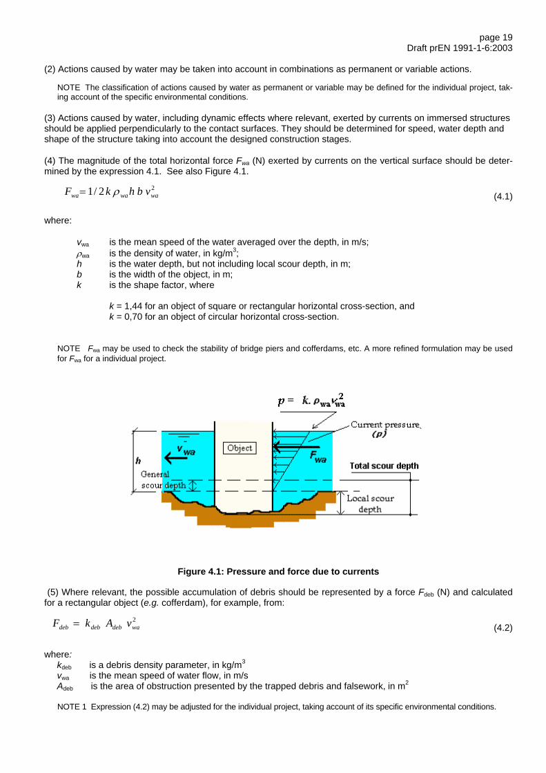
page 19Draft prEN 1991-1-6:2003
(2) Actions caused by water may be taken into account in combinations as permanent or variable actions.
NOTE The classification of actions caused by water as permanent or variable may be defined for the individual project, tak-ing account of the specific environmental conditions.
(3) Actions caused by water, including dynamic effects where relevant, exerted by currents on immersed structuresshould be applied perpendicularly to the contact surfaces. They should be determined for speed, water depth andshape of the structure taking into account the designed construction stages.
(4) The magnitude of the total horizontal force Fwa (N) exerted by currents on the vertical surface should be deter-mined by the expression 4.1. See also Figure 4.1.
22/1 wawawa vbhkF ρ= (4.1)
where:
vwa is the mean speed of the water averaged over the depth, in m/s;ρwa is the density of water, in kg/m3;h is the water depth, but not including local scour depth, in m;b is the width of the object, in m;k is the shape factor, where
k = 1,44 for an object of square or rectangular horizontal cross-section, andk = 0,70 for an object of circular horizontal cross-section.
NOTE Fwa may be used to check the stability of bridge piers and cofferdams, etc. A more refined formulation may be usedfor Fwa for a individual project.
Figure 4.1: Pressure and force due to currents
(5) Where relevant, the possible accumulation of debris should be represented by a force Fdeb (N) and calculatedfor a rectangular object (e.g. cofferdam), for example, from:
2wadebdebdeb vAkF = (4.2)
where:kdeb is a debris density parameter, in kg/m3
vwa is the mean speed of water flow, in m/sAdeb is the area of obstruction presented by the trapped debris and falsework, in m2
NOTE 1 Expression (4.2) may be adjusted for the individual project, taking account of its specific environmental conditions.

page 20Draft prEN 1991-1-6:2003
NOTE 2 The recommended value of kdeb is 666 kg/m3.
(6) Actions due to ice, including floating ice, should be taken into account where relevant.
NOTE 1 The actions may be considered as a distributed load and acting in the direction of current flow equal to the highest orlower water levels, whichever gives the most unfavourable effects.
NOTE 2 The loads and water levels may be defined in the National Annex or for the individual project.
(7) Actions from rainwater should be taken into account for the conditions where there may be collection of water suchas ponding effects from, for example, inadequate drainage, imperfections of surfaces, deflections and/or failure of de-watering devices.
4.10 Actions due to atmospheric icing
(1)P Actions due to atmospheric icing shall be taken into account where relevant.
NOTE The representative values of these actions may be defined in the National Annex or for the individual project. Guid-ance may be found in EN 1993-3 and in ISO 12494.
4.11 Construction loads
4.11.1 General
(1) Construction loads (Qc) (actions to be included for consideration are defined in Table 4.1) may be representedin the appropriate design situations (see EN 1990), either, as one single variable action, or where appropriate dif-ferent types of construction loads may be grouped and applied as a single variable action. Single and/or a groupingof construction loads should be considered to act simultaneously with non construction loads as appropriate.
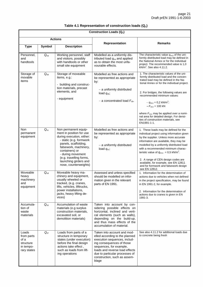
page 21Draft prEN 1991-1-6:2003
Table 4.1 Representation of construction loads (Qc)
Construction Loads (Qc)
Actions
Type Symbol DescriptionRepresentation Remarks
Personnel,andhandtools
Qca Working personnel, staffand visitors, possiblywith handtools or othersmall site equipment
Modelled as a uniformly dis-tributed load qca and appliedas to obtain the most unfa-vourable effects.
The characteristic value qca,k of the uni-formly distributed load may be defined inthe National Annex or for the individualproject. The recommended value is 1,0kN/m2. See also 4.11.2.
Storage ofmovableitems
Qcb Storage of moveableitems, e.g.:
- building and construc-tion materials, precastelements, and
- equipment
Modelled as free actions andbe represented as appropriateby:
− a uniformly distributedload qcb;
− a concentrated load Fcb.
1. The characteristic values of the uni-formly distributed load and the concen-trated load may be defined in the Na-tional Annex or for the individual project.
2. For bridges, the following values arerecommended minimum values:
− qcb,k = 0,2 kN/m2;− Fcb,k = 100 kN
where Fcb,k may be applied over a nomi-nal area for detailed design. For densi-ties of construction materials, seeEN1991-1-1.
Nonpermanentequipment
Qcc Non permanent equip-ment in position for useduring execution, either:
- static (e.g. formworkpanels, scaffolding,falsework, machinery,containers) or- during movement(e.g. travelling forms,launching girders andnose, counterweights)
Modelled as free actions andbe represented as appropriateby:
− a uniformly distributedload qcc;
1. These loads may be defined for theindividual project using information givenby the supplier. Unless more accurateinformation are available, they may bemodelled by a uniformly distributed loadwith a recommended minimum charac-teristic value of qcc,k = 0,5 kN/m2.
2. A range of CEN design codes areavailable, for example, see EN 12811and for formwork and falsework designsee EN 12812.
Moveableheavymachineryandequipment
Qcd Moveable heavy ma-chinery and equipment,usually wheeled ortracked, (e.g. cranes,lifts, vehicles, lifttrucks,power installations,jacks, heavy lifting de-vices)
Assessed and unless specifiedshould be modelled on infor-mation given in the relevantparts of EN 1991.
1. Information for the determination ofactions due to vehicles when not definedin the project specification, may be foundin EN 1991-2, for example.
2. Information for the determination ofactions due to cranes is given in EN1991-3.
Accumula-tion ofwastematerials
Qce Accumulation of wastematerials (e.g surplusconstruction materials,excavated soil, ordemolition materials)
Taken into account by con-sidering possible effects onhorizontal, inclined and verti-cal elements (such as walls),depending on the build-up,and thus mass effects of theaccumulation of material.
Loadsfrom partsof astructurein tempo-rary states
Qcf Loads from parts of astructure in temporarystates (under execution)before the final designactions take effect ,such as loads from lift-ing operations
Taken into account and mod-elled according to the plannedexecution sequences, includ-ing consequences of thosesequences, for example,loads and reverse load effectsdue to particular processes ofconstruction, such as assem-blage
See also 4.11.2 for additional loads dueto concrete being fresh

page 22Draft prEN 1991-1-6:2003
NOTE 1 See EN 1990 and EN 1991 for advice on the simultaneity of non construction and construction loads.
NOTE 2 Groupings of loads to be taken into account are dependent on the individual project.
NOTE 3 See also Table 2.2.
(2)P Characteristic values of construction loads, including vertical and horizontal components where relevant, shall bedetermined according to the technical requirements for the execution of the works and the requirements of EN 1990.
NOTE 1 Recommended values of ψ factors for construction loads are given in Annex A1 of this Standard for buildings, andin Annex A2 to EN 1990 for bridges.
NOTE 2 Additional loads may need to be taken into account. These loads may be defined for the individual project.
(3)P Horizontal actions resulting from the effects of construction loads shall be determined and taken into account inthe structural design of a partly completed structure as well as the completed structure.
(4)P When construction loads cause dynamic effects, these effects shall be taken into account.
NOTE See also 3.1 (10) and EN 1990, Annexes A1 and A2.
4.11.2 Construction loads during the casting of concrete
(1) Actions to be taken into account simultaneously during the casting of concrete may include working personnelwith small site equipment (Qca), formwork and loadbearing members (Qcc) and the weight of fresh concrete (whichis one example of Qcf), as appropriate.
NOTE 1 For the density of fresh concrete see EN 1991-1-1 Table A.1.
NOTE 2 Qca, Qcc and Qcf may be given in the National Annex
NOTE 3 Recommended values for fresh concrete (Qcf) may be taken from Table 4.2 and EN 1991-1-1, Table A.1. Othervalues may have to be defined, for example, when using self-levelling concrete or precast products.
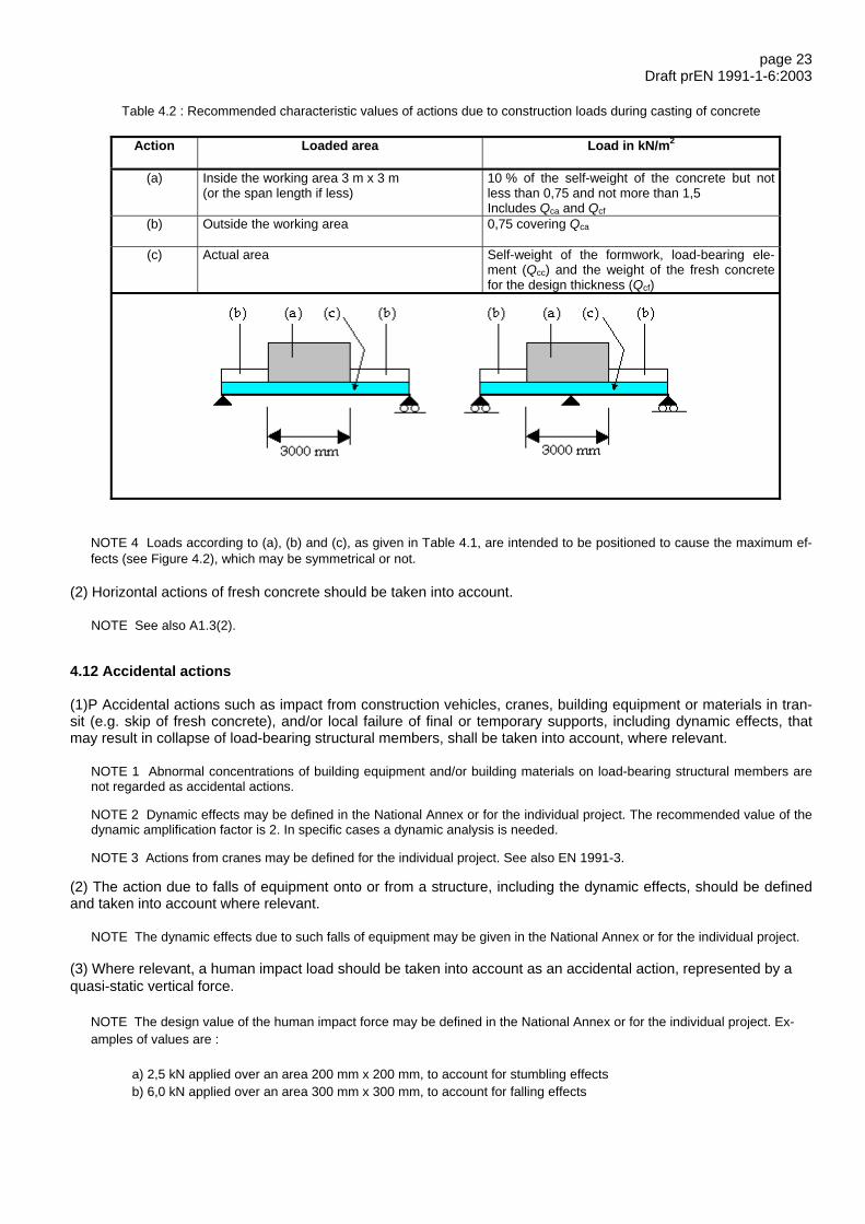
page 23Draft prEN 1991-1-6:2003
Table 4.2 : Recommended characteristic values of actions due to construction loads during casting of concrete
Action Loaded area Load in kN/m2
(a) Inside the working area 3 m x 3 m (or the span length if less)
10 % of the self-weight of the concrete but notless than 0,75 and not more than 1,5Includes Qca and Qcf
(b) Outside the working area 0,75 covering Qca
(c) Actual area Self-weight of the formwork, load-bearing ele-ment (Qcc) and the weight of the fresh concretefor the design thickness (Qcf)
NOTE 4 Loads according to (a), (b) and (c), as given in Table 4.1, are intended to be positioned to cause the maximum ef-fects (see Figure 4.2), which may be symmetrical or not.
(2) Horizontal actions of fresh concrete should be taken into account.
NOTE See also A1.3(2).
4.12 Accidental actions
(1)P Accidental actions such as impact from construction vehicles, cranes, building equipment or materials in tran-sit (e.g. skip of fresh concrete), and/or local failure of final or temporary supports, including dynamic effects, thatmay result in collapse of load-bearing structural members, shall be taken into account, where relevant.
NOTE 1 Abnormal concentrations of building equipment and/or building materials on load-bearing structural members arenot regarded as accidental actions.
NOTE 2 Dynamic effects may be defined in the National Annex or for the individual project. The recommended value of thedynamic amplification factor is 2. In specific cases a dynamic analysis is needed.
NOTE 3 Actions from cranes may be defined for the individual project. See also EN 1991-3.
(2) The action due to falls of equipment onto or from a structure, including the dynamic effects, should be definedand taken into account where relevant.
NOTE The dynamic effects due to such falls of equipment may be given in the National Annex or for the individual project.
(3) Where relevant, a human impact load should be taken into account as an accidental action, represented by aquasi-static vertical force.
NOTE The design value of the human impact force may be defined in the National Annex or for the individual project. Ex-amples of values are :
a) 2,5 kN applied over an area 200 mm x 200 mm, to account for stumbling effects b) 6,0 kN applied over an area 300 mm x 300 mm, to account for falling effects

page 24Draft prEN 1991-1-6:2003
(4) The effects of the actions described in paragraphs (1), (2) and (3) above should be assessed to determine thepotential for inducing movement in the structure, and also the extent and effect of any such movement should bedetermined, with the potential for progressive collapse assessed.
NOTE: See also EN1991-1-7.
(5) Accidental actions used for design situations should be taken into account for any changes. To ensure that theappropriate design criteria is applied at all times, measures should be taken as work proceeds.
(6) Fire actions should be taken into account, where appropriate.
4.13 Seismic actions
(1) Seismic actions should be determined according to EN 1998, taking into account the reference period of theconsidered transient situation.
(2) The design values of ground acceleration and the importance factor γI should be defined.
NOTE The design values of ground acceleration and the importance factor γI may be defined in the National Annex or forthe individual project.
page 25Draft prEN 1991-1-6:2003
Annex A1(normative)
Supplementary rules for buildings
A1.1 Ultimate limit states
(1) For transient, accidental and seismic design situations the ultimate limit state verifications should be based oncombinations of actions applied with the partial factors for actions γF and the appropriate ψ factors.
NOTE 1 For values of γF and ψ factors see EN 1990, Annex A1.
NOTE 2 Representative values of the variable action due to construction loads may be set by the National Annex, within arecommended range of =0ψ 0,6 to 1,0. The recommended value of 0ψ is 1,0.
The minimum recommended value of 2ψ is 0,2 and it is further recommended that values below 0,2 are not selected.
NOTE 3 1ψ does not apply to construction loads during execution.
A1.2 Serviceability limit states
(1) For the verification of serviceability limit states, the combinations of actions to be taken into account should be thecharacteristic and the quasi-permanent combinations as defined in EN 1990.
NOTE For recommended values of ψ−factors see A1.1, Notes 1 and 2.
A1.3 Horizontal actions
(1)P Further to 4.11.1 (3), horizontal actions resulting from, for example, wind forces and the effects of sway imperfec-tions and sway deformations shall be taken into account.
NOTE: See also 4.7 and EN 1990, 3.5(7).
(2) Nominal horizontal forces (Fhn) may be applied only when such a method can be justified as appropriate and rea-sonable for a particular case. In such cases, the determined nominal horizontal forces should be applied at locationsto be give the worst effects, and may not always correspond to those of the vertical loads.
NOTE The characteristic values of these equivalent horizontal forces may be defined in the National Annex or for the indi-vidual project. The recommended value is 3 % of the vertical loads from the most unfavourable combination of actions.
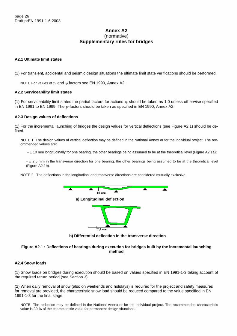
page 26Draft prEN 1991-1-6:2003
Annex A2(normative)
Supplementary rules for bridges
A2.1 Ultimate limit states
(1) For transient, accidental and seismic design situations the ultimate limit state verifications should be performed.
NOTE For values of γF and ψ factors see EN 1990, Annex A2.
A2.2 Serviceability limit states
(1) For serviceability limit states the partial factors for actions γF should be taken as 1,0 unless otherwise specifiedin EN 1991 to EN 1999. The ψ-factors should be taken as specified in EN 1990, Annex A2.
A2.3 Design values of deflections
(1) For the incremental launching of bridges the design values for vertical deflections (see Figure A2.1) should be de-fined.
NOTE 1 The design values of vertical deflection may be defined in the National Annex or for the individual project. The rec-ommended values are:
− ± 10 mm longitudinally for one bearing, the other bearings being assumed to be at the theoretical level (Figure A2.1a);
− ± 2,5 mm in the transverse direction for one bearing, the other bearings being assumed to be at the theoretical level(Figure A2.1b).
NOTE 2 The deflections in the longitudinal and transverse directions are considered mutually exclusive.
Figure A2.1 : Deflections of bearings during execution for bridges built by the incremental launchingmethod
A2.4 Snow loads
(1) Snow loads on bridges during execution should be based on values specified in EN 1991-1-3 taking account ofthe required return period (see Section 3).
(2) When daily removal of snow (also on weekends and holidays) is required for the project and safety measuresfor removal are provided, the characteristic snow load should be reduced compared to the value specified in EN1991-1-3 for the final stage.
NOTE The reduction may be defined in the National Annex or for the individual project. The recommended characteristicvalue is 30 % of the characteristic value for permanent design situations.
a) Longitudinal deflection
b) Differential deflection in the transverse direction

page 27Draft prEN 1991-1-6:2003
(3) For the verification of the static equilibrium (EQU), and when justified by climatic conditions and duration of theconstruction, the characteristic snow load should be assumed to be uniformly distributed in the areas giving unfa-vourable action effects and should be equal to 75 % of the characteristic value for permanent design situations re-sulting from EN 1991-1-3.
NOTE The conditions of application of this rule and the reduced value may be defined in the National Annex.
A2.5 Construction loads
(1) For the incremental launching of bridges horizontal forces due to friction effects should be determined, and appliedbetween the bridge structure, the bearings and the piers, with dynamic action effects taken into account where appro-priate.
(2) The design value of the horizontal friction forces should be evaluated, should be not less than x % of verticalloads, and should be determined to give the least favourable effects.
NOTE The value of x % may be specified in the National Annex. The recommended value is 10 %.
(3) The horizontal friction forces at every pier should be determined with the appropriate friction coefficients, µmin andµmax .
NOTE 1 The friction coefficients, µmin and µmax, may be defined in the National Annex or for the individual project.
NOTE 2 Unless more accurate values are available from tests for movements on very low friction surfaces (e.g. PTFE -Polytetrafluoroethylene) the recommended values are :
µmin = 0
µmax = 0,04

page 28Draft prEN 1991-1-6:2003
Annex B(informative)
Actions on structures during alteration, reconstruction or demolition
(1) Characteristic and other representative values of actions should be determined in accordance with EN 1990.
(2) The actual performance of structures affected by deterioration should be taken into account in the verification ofthe stages for reconstruction or demolition. The investigation of structural conditions to enable the identification ofthe load-bearing capacity of the structure and prevent unpredictable behaviour during reconstruction or demolitionshould be undertaken.
(3) Guidance for the most common actions and methods for their assessment is provided in Section 4. How-ever, some construction loads during reconstruction or demolition may be different in characteristics and repre-sention from those shown in Tables 2.2 and 4.1, and their effects on all relevant structures under relevant tran-sient design situations should be verified.
(4) Combinations of actions for various design situations should be as given in EN 1990 and its Annexes A1 andA2.
(5) Unless more specific information is known the values of ψ factors recommended for buildings in Annex A1and EN 1990 Annex A1 and for bridges in EN 1990 Annex A2, may be considered in the design for transientdesign situations.
(6) All imposed loads, including traffic loads, should be considered if the part of structure remains in use duringits reconstruction or partial demolition. These loads may vary at different transient stages. Traffic loads shouldinclude, for example, impact and horizontal forces from vehicles, wind actions on vehicles, aerodynamic effectsfrom passing vehicles and trains where relevant.
(7) Reduction of traffic loads from their final design values should not be made unless the use of the structural partis monitored and regularly supervised.
(8) The reliability for the remaining structure or parts of the structure under reconstruction, partial or full demolitionshould be consistent with that considered in the Eurocodes for completed structures or parts of structures.
(9) The actions due to the works should not adversely affect neighbouring structures by, for example, removing orimposing loads that may cause instability.
(10) Construction loads specific for reconstruction or demolition should be determined taking into account, for ex-ample, methods and arrangements of storing materials, the techniques used during reconstruction or demolition,the execution system and the particular stages of work. Construction loads during reconstruction or demolitionmay also include the effects of storage from disassembled materials or dismantled elements, including horizontalactions.
(11) Dynamic effects should be considered where it is anticipated that activities during reconstruction or demolitionwill cause such effects.

page 29Draft prEN 1991-1-6:2003
Bibliography
EN 1337 Structural bearings
EN 12811 Temporary works equipment
EN 12812 Falsework. Performance requirements and general design
EN 13670 Execution of concrete structure
ISO 12494 Atmospheric Icing of Structures