Embed Size (px)
Citation preview
TÜRK STANDARDITURKISH STANDARD
TS EN 1991-1-3Ocak 2004
ICS 91.010.30
EUROCODE 1: YAPILARA OLAN ETKİLER - BÖLÜM 1-3: GENEL ETKİLER - KAR YÜKLERİ Eurocode 1 - Actions on structures - Part 1-3: General actions - Snow loads
TÜRK STANDARDLARI ENSTİTÜSÜ Necatibey Caddesi No.112 Bakanlıklar/ANKARA

TÜRK STANDARDI
Ön söz – Bu standard, Türk Standardları Enstitüsü tarafından ilgili Avrupa standardı esas alınarak Türk Standardı
olarak kabul edilmiştir.
EUROPEAN STANDARD
NORME EUROPÉENNE
EUROPÄISCHE NORM
EN 1991-1-3
July 2003
ICS 91.010.30 Supersedes ENV 1991-2-3:1995
English version
Eurocode 1 - Actions on structures - Part 1-3: General actions -Snow loads
Eurocode 1 - Actions sur les structures - Partie 1-3: Actionsgénérales - Charges de neige
Eurocode 1 - Einwirkungen auf Tragwerke - Teil 1-3:Allgemeine Einwirkungen-Schneelasten
This European Standard was approved by CEN on 9 October 2002.
CEN members are bound to comply with the CEN/CENELEC Internal Regulations which stipulate the conditions for giving this EuropeanStandard the status of a national standard without any alteration. Up-to-date lists and bibliographical references concerning such nationalstandards may be obtained on application to the Management Centre or to any CEN member.
This European Standard exists in three official versions (English, French, German). A version in any other language made by translationunder the responsibility of a CEN member into its own language and notified to the Management Centre has the same status as the officialversions.
CEN members are the national standards bodies of Austria, Belgium, Czech Republic, Denmark, Finland, France, Germany, Greece,Hungary, Iceland, Ireland, Italy, Luxembourg, Malta, Netherlands, Norway, Portugal, Slovakia, Spain, Sweden, Switzerland and UnitedKingdom.
EUROPEAN COMMITTEE FOR STANDARDIZATIONC OM ITÉ EUR OP ÉEN DE NOR M ALIS AT IONEUROPÄISCHES KOMITEE FÜR NORMUNG
Management Centre: rue de Stassart, 36 B-1050 Brussels
© 2003 CEN All rights of exploitation in any form and by any means reservedworldwide for CEN national Members.
Ref. No. EN 1991-1-3:2003 E
EN 1991-1-3:2003 (E)
2
CONTENTS Page
Foreword 4
1. Section 1 General 8
1.1. Scope 8
1.2. Normative references 9
1.3. Assumptions 9
1.4. Distinction between Principles and Application Rules 9
1.5. Design assisted by testing 9
1.6. Terms and Definitions 10
1.7. Symbols 11
2. Section 2 Classification of actions 13
3. Section 3 Design situations 14
3.1. General 14
3.2. Normal conditions 14
3.3. Exceptional conditions 14
4. Section 4 Snow load on the ground 16
4.1. Characteristic values 16
4.2. Other representative values 16
4.3. Treatment of exceptional snow loads on the ground 17
5. Section 5 Snow load on roofs 17
5.1. Nature of the load 17
5.2. Load arrangements 18
5.3. Roof shape coefficients 205.3.1. General 205.3.2. Monopitch roofs 215.3.3. Pitched roofs 225.3.4. Multi-span roofs 235.3.5. Cylindrical roofs 245.3.6. Roof abutting and close to taller construction works25
6. Section 6 Local effects 28
6.1. General 28
6.2. Drifting at projections and obstructions 28
6.3. Snow overhanging the edge of a roof 29
6.4. Snow loads on snowguards and other obstacles 30
EN 1991-1-3:2003 (E)
3
ANNEX A 31
Design situations and load arrangements to be used for differentlocations 31
ANNEX B 33
Snow load shape coefficients for exceptional snow drifts 33
ANNEX C 38
European Ground Snow Load Maps 38
ANNEX D 53
Adjustment of the ground snow load according to return period 53
ANNEX E 55
Bulk weight density of snow 55
Bibliography 56

EN 1991-1-3:2003 (E)
4
Foreword
This document (EN 1991-1-3:2003) has been prepared by TechnicalCommittee CEN/TC250 “Structural Eurocodes”, the Secretariat of which is heldby BSI.
This European Standard shall be given the status of a National Standard,either by publication of an identical text or by endorsement, at the latest byJanuary 2004, and conflicting National Standards shall will be withdrawn atlatest by January 2004.
This document supersedes ENV 1991-2-3:1995.
CEN/TC250 is responsible for all Structural Eurocodes.
Annexes A and B are normative. Annexes C, D and E are informative.
According to the CEN-CENELEC Internal Regulations, the National StandardOrganisations of the following countries are bound to implement this EuropeanStandard: Austria, Belgium, Czech Republic, Denmark, Finland, France,Germany, Greece, Hungary, Iceland, Ireland, Italy, Luxembourg, Malta,Netherlands, Norway, Portugal, Slovakia, Spain, Sweden, Switzerland and theUnited Kingdom.
Background of the Eurocode programme
In 1975, the Commission of the European Community decided on an actionprogramme in the field of construction, based on article 95 of the Treaty. Theobjective of the programme was the elimination of technical obstacles to tradeand the harmonisation of technical specifications.
Within this action programme, the Commission took the initiative to establish aset of harmonised technical rules for the design of construction works which, ina first stage, would serve as an alternative to the national rules in force in theMember States and, ultimately, would replace them.
For fifteen years, the Commission, with the help of a Steering Committee withRepresentatives of Member States, conducted the development of theEurocodes programme, which led to the first generation of European codes inthe 1980’s.
In 1989, the Commission and the Member States of the EU and EFTA decided,on the basis of an agreement1 between the Commission and CEN, to transferthe preparation and the publication of the Eurocodes to the CEN through aseries of Mandates, in order to provide them with a future status of EuropeanStandard (EN). This links de facto the Eurocodes with the provisions of all theCouncil’s Directives and/or Commission’s Decisions dealing with European
1 Agreement between the Commission of the European Communities and the European Committee for Standardisation
(CEN) concerning the work on EUROCODES for the design of building and civil engineering works (BC/CEN/03/89).

EN 1991-1-3:2003 (E)
5
standards (e.g. the Council Directive 89/106/EEC on construction products andCouncil Directives 93/37/EEC, 92/50/EEC and 89/440/EEC on public worksand services and equivalent EFTA Directives initiated in pursuit of setting upthe internal market).
The Structural Eurocode programme comprises the following standardsgenerally consisting of a number of Parts:
EN 1990 Eurocode: Basis of Structural DesignEN 1991 Eurocode 1: Actions on structuresEN 1992 Eurocode 2: Design of concrete structuresEN 1993 Eurocode 3: Design of steel structuresEN 1994 Eurocode 4: Design of composite steel and concrete
structuresEN 1995 Eurocode 5: Design of timber structuresEN 1996 Eurocode 6: Design of masonry structuresEN 1997 Eurocode 7: Geotechnical designEN 1998 Eurocode 8: Design of structures for earthquake resistanceEN 1999 Eurocode 9: Design of aluminium structures
Eurocode standards recognise the responsibility of regulatory authorities ineach Member State and have safeguarded their right to determine valuesrelated to regulatory safety matters at national level where these continue tovary from State to State.
Status and field of application of Eurocodes
The Member States of the EU and EFTA recognise that EUROCODES serveas reference documents for the following purposes :– as a means to prove compliance of building and civil engineering works withthe essential requirements of Council Directive 89/106/EEC, particularlyEssential Requirement N°1 – Mechanical resistance and stability – andEssential Requirement N°2 – Safety in case of fire ;
– as a basis for specifying contracts for construction works and relatedengineering services ;
– as a framework for drawing up harmonised technical specifications forconstruction products (ENs and ETAs)
The Eurocodes, as far as they concern the construction works themselves,have a direct relationship with the Interpretative Documents2 referred to inArticle 12 of the CPD, although they are of a different nature from harmonisedproduct standards3. Therefore, technical aspects arising from the Eurocodes 2 According to Art. 3.3 of the CPD, the essential requirements (ERs) shall be given concrete form in interpretative documents for
the creation of the necessary links between the essential requirements and the mandates for hENs and ETAGs/ETAs.3 According to Art. 12 of the CPD the interpretative documents shall :a) give concrete form to the essential requirements by harmonising the terminology and the technical bases and indicating classes or levels
for each requirement where necessary ;b) indicate methods of correlating these classes or levels of requirement with the technical specifications, e.g. methods of calculation and of
proof, technical rules for project design, etc. ;c) serve as a reference for the establishment of harmonised standards and guidelines for European technical approvals.The Eurocodes, de facto, play a similar role in the field of the ER 1 and a part of ER 2.

EN 1991-1-3:2003 (E)
6
work need to be adequately considered by CEN Technical Committees and/orEOTA Working Groups working on product standards with a view to achievinga full compatibility of these technical specifications with the Eurocodes.
The Eurocode standards provide common structural design rules for everydayuse for the design of whole structures and component products of both atraditional and an innovative nature. Unusual forms of construction or designconditions are not specifically covered and additional expert consideration willbe required by the designer in such cases.
National Standards implementing Eurocodes
The National Standards implementing Eurocodes will comprise the full text ofthe Eurocode (including any annexes), as published by CEN, which may bepreceded by a National title page and National foreword, and may be followedby a National Annex.
The National Annex may only contain information on those parameters whichare left open in the Eurocode for national choice, known as NationallyDetermined Parameters, to be used for the design of buildings and civilengineering works to be constructed in the country concerned, i.e. :
– values for partial factors and/or classes where alternatives are given in theEurocode,
– values to be used where a symbol only is given in the Eurocode,
– country specific data (geographical, climatic etc.), e.g. snow map,
– the procedure to be used where alternative procedures are given in theEurocode.
It may also contain
– decisions on the application of informative annexes,
– references to non-contradictory complementary information to assist the userto apply the Eurocode.
Links between Eurocodes and harmonised technical specifications (ENsand ETAs) for products
There is a need for consistency between the harmonised technicalspecifications for construction products and the technical rules for works4.Furthermore, all the information accompanying the CE Marking of theconstruction products which refer to Eurocodes should clearly mention whichNationally Determined Parameters have been taken into account.
Introduction - Additional information specific for EN 1991-1-3EN 1991 1-3 gives design guidance and actions from snow for the structuraldesign of buildings and civil engineering works.
4 see Art.3.3 and Art.12 of the CPD, as well as clauses 4.2, 4.3.1, 4.3.2 and 5.2 of ID 1.

EN 1991-1-3:2003 (E)
7
EN 1991 1-3 is intended for clients, designers, contractors and publicauthorities.
EN 1991 1-3 is intended to be used with EN 1990:2002, the other Parts of EN1991 and EN 1992- EN 1999 for the design of structures.
National Annex for EN1991-1-3This standard gives alternative procedures, values and recommendations forclasses with notes indicating where national choices may have to be made.Therefore the National Standard implementing EN 1991-1-3 should have aNational Annex containing nationally determined parameters to be used for thedesign of buildings and civil engineering works to be constructed in therelevant country.
National choice is allowed in EN 1991-1-3 through clauses:1.1(2), 1.1(4)2(3), 2(4)3.3(1), 3.3(3),4.1(1), 4.2(1), 4.3(1)5.2(1), 5.2(4), 5.2(5), 5.2(6), 5.2(7), 5.3.3(4), 5.3.4(3), 5.3.5(1), 5.3.5(3),5.3.6(1), 5.3.6(3)6.2(2), 6.3(1), 6.3(2)A(1) (through Table A1)

EN 1991-1-3:2003 (E)
8
1. Section 1 General
1.1. Scope
(1) EN 1991-1-3 gives guidance to determine the values of loads due to snowto be used for the structural design of buildings and civil engineering works.
(2) This Part does not apply for sites at altitudes above 1 500 m, unlessotherwise specified.
NOTE 1: Advice for the treatment of snow loads for altitudes above 1 500 m may be found inthe National Annex.
(3) Annex A gives information on design situations and load arrangements tobe used for different locations.
NOTE: These different locations may be identified by the National Annex.
(4) Annex B gives shape coefficients to be used for the treatment ofexceptional snow drifts.
NOTE: The use of Annex B is allowed through the National Annex.
(5) Annex C gives characteristic values of snow load on the ground based onthe results of work carried out under a contract specific to this Eurocode, toDGIII / D3 of the European Commission.The objectives of this Annex are:– to give information to National Competent Authorities to help them to redraft
and update their national maps;– to help to ensure that the established harmonised procedures used to
produce the maps in this Annex are used in the member states for treatingtheir basic snow data.
(6) Annex D gives guidance for adjusting the ground snow loads according tothe return period.
(7) Annex E gives information on the bulk weight density of snow.
(8) This Part does not give guidance on specialist aspects of snow loading, forexample:– impact snow loads resulting from snow sliding off or falling from a higher
roof;– the additional wind loads which could result from changes in shape or size
of the construction works due to the presence of snow or the accretion ofice;
– loads in areas where snow is present all year round;– ice loading;– lateral loading due to snow (e.g. lateral loads exerted by drifts);– snow loads on bridges.

EN 1991-1-3:2003 (E)
9
1.2. Normative references
This European Standard incorporates by dated or undated referencesprovisions from other publications. These normative references are cited at theappropriate place in the text, and publications are listed hereafter.For dated references, subsequent amendments to, or revisions of any of thesepublications apply to this European Standard only when incorporated in it byamendment or revision. For undated references, the latest edition of thepublication referred to applies (including amendments).
EN 1990:2002 Eurocode: Basis of structural design
EN 1991-1-1:2002 Eurocode 1: Actions on structures Part 1-1: Generalactions: Densities self weight and imposed loads forbuildings
NOTE: The following European Standards, which are published or in preparation, are cited innormative clauses
EN 1991-2 Eurocode 1: Actions on structuresPart 2: Traffic loads on bridges
1.3. Assumptions
The statements and assumptions given in EN 1990:2002, 1.3 apply to EN1991-1-3.
1.4. Distinction between Principles and Application Rules
The rules given in EN 1990:2002, 1.4 apply to EN 1991-1-3.
1.5. Design assisted by testing
In some circumstances tests and proven and/or properly validated numericalmethods may be used to obtain snow loads on the construction works.
NOTE: The circumstances are those agreed for an individual project, with the client and therelevant Authority.
EN 1991-1-3:2003 (E)
10
1.6. Terms and Definitions
For the purposes of this European standard, a basic list of terms definitionsgiven in EN 1990:2002, 1.5 apply together with the following.
1.6.1characteristic value of snow load on the groundsnow load on the ground based on an annual probability of exceedence of0,02, excluding exceptional snow loads.
1.6.2altitude of the siteheight above mean sea level of the site where the structure is to be located, oris already located for an existing structure.
1.6.3exceptional snow load on the groundload of the snow layer on the ground resulting from a snow fall which has anexceptionally infrequent likelihood of occurring.
NOTE: See notes to 2(3) and 4.3(1).
1.6.4characteristic value of snow load on the roofproduct of the characteristic snow load on the ground and appropriatecoefficients.
NOTE: These coefficients are chosen so that the probability of the calculated snow load on theroof does not exceed the probability of the characteristic value of the snow load on the ground.
1.6.5undrifted snow load on the roofload arrangement which describes the uniformly distributed snow load on theroof, affected only by the shape of the roof, before any redistribution of snowdue to other climatic actions.
1.6.6drifted snow load on the roofload arrangement which describes the snow load distribution resulting fromsnow having been moved from one location to another location on a roof, e.g.by the action of the wind.
1.6.7roof snow load shape coefficientratio of the snow load on the roof to the undrifted snow load on the ground,without the influence of exposure and thermal effects.
EN 1991-1-3:2003 (E)
11
1.6.8thermal coefficientcoefficient defining the reduction of snow load on roofs as a function of theheat flux through the roof, causing snow melting.
1.6.9exposure coefficientcoefficient defining the reduction or increase of load on a roof of an unheatedbuilding, as a fraction of the characteristic snow load on the ground.
1.6.10load due to exceptional snow driftload arrangement which describes the load of the snow layer on the roofresulting from a snow deposition pattern which has an exceptionally infrequentlikelihood of occurring.
1.7. Symbols
(1) For the purpose of this European standard, the following symbols apply.
NOTE: The notation used is based on ISO 3898
(2) A basic list of notations is given in EN 1990:2002 1.6, and the additionalnotations below are specific to this Part.
Latin upper case letters
Ce Exposure coefficient
Ct Thermal coefficient
Cesl Coefficient for exceptional snow loads
A Site altitude above sea level [m]
Se Snow load per metre length due to overhang [kN/m]
Fs Force per metre length exerted by a sliding mass of snow [kN/m]
Latin lower case letters
b Width of construction work [m]
d Depth of the snow layer [m]
h Height of construction work [m]
k Coefficient to take account of the irregular shape of snow (see also 6.3)
ls Length of snow drift or snow loaded area [m]

EN 1991-1-3:2003 (E)
12
s Snow load on the roof [kN/m2]
sk Characteristic value of snow on the ground at the relevant site [kN/m2]
sAd Design value of exceptional snow load on the ground [kN/m2]
Greek Lower case letters
� Pitch of roof, measured from horizontal [o]
� Angle between the horizontal and the tangent to the curve for acylindrical roof [o]
� Weight density of snow [kN/m3]
� snow load shape coefficient
�0 Factor for combination value of a variable action
�1 Factor for frequent value of a variable action
�2 Factor for quasi-permanent value of a variable action
NOTE: For the purpose of this standard the units specified in the above list apply.

EN 1991-1-3:2003 (E)
13
2. Section 2 Classification of actions
(1)P Snow loads shall be classified as variable, fixed actions (see also 5.2),unless otherwise specified in this standard, see EN 1990:2002, 4.1.1 (1)P and4.1.1 (4).
(2) Snow loads covered in this standard should be classified as static actions,see EN 1990:2002, 4.1.1 (4).
(3) In accordance with EN 1990:2002, 4.1.1 (2), for the particular conditiondefined in 1.6.3, exceptional snow loads may be treated as accidental actionsdepending on geographical locations.
NOTE: The National Annex may give the conditions of use (which may include geographicallocations) of this clause.
(4) In accordance with EN 1990:2002, 4.1.1 (2), for the particular conditiondefined in 1.6.10, loads due to exceptional snow drifts may be treated asaccidental actions, depending on geographical locations.
NOTE: The National Annex may give the conditions of use (which may include geographicallocations) of this clause.
EN 1991-1-3:2003 (E)
14
3. Section 3 Design situations
3.1. General
(1)P The relevant snow loads shall be determined for each design situationidentified, in accordance with EN 1990:2002, 3.5.
(2) For local effects described in Section 6 the persistent/transient designsituation should be used.
3.2. Normal conditions
(1) For locations where exceptional snow falls (see 2(3)) and exceptional snowdrifts (see 2(4)) are unlikely to occur, the transient/persistent design situationshould be used for both the undrifted and the drifted snow load arrangementsdetermined using 5.2(3)P a) and 5.3.
NOTE: See Annex A case A.
3.3. Exceptional conditions(1) For locations where exceptional snow falls (see 2(3)) may occur but notexceptional snow drifts (see 2(4)) the following applies:a) the transient/persistent design situation should be used for both the
undrifted and the drifted snow load arrangements determined using5.2(3)P a) and 5.3, and
b) the accidental design situation should be used for both the undrifted andthe drifted snow load arrangements determined using 4.3, 5.2(3)P (b) and5.3.
NOTE 1: See Annex A case B1.
NOTE 2: The National Annex may define which design situation applies for a particular localeffect described in Section 6.
(2) For locations where exceptional snow falls (see 2(3)) are unlikely to occurbut exceptional snow drifts (see 2(4)) may occur the following applies:a) the transient/persistent design situation should be used for both the
undrifted and the drifted snow load arrangements determined using5.2(3)P a) and 5.3, and
b) the accidental design situation should be used for snow load casesdetermined using 5.2(3)P c) and Annex B.
NOTE: See Annex A case B2.
(3) For locations where both exceptional snow falls (see 2(3)) and exceptionalsnow drifts (see 2(4)) may occur the following applies:

EN 1991-1-3:2003 (E)
15
a) the transient/persistent design situation should be used for both theundrifted and the drifted snow load arrangements determined using5.2(3)P a) and 5.3, and
b) the accidental design situation should be used for both the undrifted andthe drifted snow load arrangements determined using 4.3, 5.2(3)P(b) and5.3.
c) the accidental design situation should be used for the snow load casesdetermined using 5.2(3)P c) and Annex B.
NOTE 1: See Annex A case B3.
NOTE 2: The National Annex may define which design situation to apply for a particular localeffect described in Section 6.
EN 1991-1-3:2003 (E)
16
4. Section 4 Snow load on the ground
4.1. Characteristic values
(1) The characteristic value of snow load on the ground (sk) should bedetermined in accordance with EN 1990:2002, 4.1.2 (7)P and the definition forcharacteristic snow load on the ground given in 1.6.1.
NOTE 1: The National Annex specifies the characteristic values to be used. To cover unusuallocal conditions the National Annex may additionally allow the client and the relevant authorityto agree upon a different characteristic value from that specified for an individual project.
NOTE 2: Annex C gives the European ground snow load map, resulting from studiescommissioned by DGIII/D-3. The National Annex may make reference to this map in order toeliminate, or to reduce, inconsistencies occurring at borderlines between countries.
(2) In special cases where more refined data is needed, the characteristicvalue of snow load on the ground (sk) may be refined using an appropriatestatistical analysis of long records taken in a well sheltered area near the site.
NOTE 1: The National Annex may give further complementary guidance.
NOTE 2: As there is usually considerable variability in the number of recorded maximum wintervalues, record periods of less than 20 years will not generally be suitable.
(3) Where in particular locations, snow load records show individual,exceptional values which cannot be treated by the usual statistical methods,the characteristic values should be determined without taking into accountthese exceptional values. The exceptional values may be considered outsidethe usual statistical methods in accordance with 4.3.
4.2. Other representative values
(1) According to EN1990:2002, 4.1.3 the other representative values for snowload on the roof are as follows:– Combination value �0 s– Frequent value �1 s– Quasi-permanent value �2 s
NOTE: The values of � may be set by the National Annex of EN 1990:2002.The recommendedvalues of the coefficients �0, �1 and �2 for buildings are dependent upon the location of thesite being considered and should be taken from EN 1990:2002, Table A1.1 or Table 4.1 below,in which the information relating to snow loads is identical.

EN 1991-1-3:2003 (E)
17
Table 4.1 Recommended values of coefficients ��0, ��1 and ��2 fordifferent locations for buildings.
Regions �0 �1 �2
FinlandIcelandNorwaySweden
0,70 0,50 0,20
Reminder of other CENmember states, for siteslocated at altitudeH > 1000 m above sealevel
0,70 0,50 0,20
Reminder of other CENmember states, for siteslocated at altitudeH � 1000 m above sealevel
0,50 0,20 0,00
4.3. Treatment of exceptional snow loads on the ground
(1) For locations where exceptional snow loads on the ground can occur, theymay be determined by:
sAd = Cesl sk (4.1)
where:
sAd is the design value of exceptional snow load on the ground for thegiven location;
Cesl is the coefficient for exceptional snow loads;sk is the characteristic value of snow load on the ground for a given
location.
NOTE: The coefficient Cesl may be set by the National Annex. The recommended value forCesl is 2,0 (see also 2(3))
5. Section 5 Snow load on roofs
5.1. Nature of the load
(1)P The design shall recognise that snow can be deposited on a roof in manydifferent patterns.
(2) Properties of a roof or other factors causing different patterns can include:
a) the shape of the roof;b) its thermal properties;

EN 1991-1-3:2003 (E)
18
c) the roughness of its surface;d) the amount of heat generated under the roof;e) the proximity of nearby buildings;f) the surrounding terrain;g) the local meteorological climate, in particular its windiness, temperature
variations, and likelihood of precipitation (either as rain or as snow).
5.2. Load arrangements
(1)P The following two primary load arrangements shall be taken into account:
– undrifted snow load on roofs (see 1.6.5);– drifted snow load on roofs (see 1.6.6).
(2) The load arrangements should be determined using 5.3; and Annex B,where specified in accordance with 3.3.
NOTE: The National Annex may specify the use of Annex B for the roof shapes described in5.3.4, 5.3.6 and 6.2, and will normally apply to specific locations where all the snow usuallymelts and clears between the individual weather systems and where moderate to high windspeeds occur during the individual weather system.
(3)P Snow loads on roofs shall be determined as follows:
a) for the persistent / transient design situations
s = �i Ce Ct sk (5.1)
b) for the accidental design situations where exceptional snow load is theaccidental action (except for the cases covered in 5.2 (3) P c)
s = �i Ce Ct sAd (5.2)
Note : See 2(3).
c) for the accidental design situations where exceptional snow drift is theaccidental action and where Annex B applies
s = �i sk (5.3)
NOTE: See 2(4).
where:
�i is the snow load shape coefficient (see Section 5.3 and Annex B)
sk is the characteristic value of snow load on the ground
sAd is the design value of exceptional snow load on the ground for agiven location (see 4.3)

EN 1991-1-3:2003 (E)
19
Ce is the exposure coefficient
Ct is the thermal coefficient
(4) The load should be assumed to act vertically and refer to a horizontalprojection of the roof area.
(5) When artificial removal or redistribution of snow on a roof is anticipated theroof should be designed for suitable load arrangements.
NOTE 1: Load arrangements according to this Section have been derived for naturaldeposition patterns only.
NOTE 2: Further guidance may be given in the National Annex.
(6) In regions with possible rainfalls on the snow and consecutive melting andfreezing, snow loads on roofs should be increased, especially in cases wheresnow and ice can block the drainage system of the roof.
NOTE: Further complementary guidance may be given in the National Annex.
(7) The exposure coefficient Ce should be used for determining the snow loadon the roof. The choice for Ce should consider the future development aroundthe site. Ce should be taken as 1,0 unless otherwise specified for differenttopographies.
NOTE: The National Annex may give the values of Ce for different topographies. Therecommended values are given in Table 5.1 below.

EN 1991-1-3:2003 (E)
20
Table 5.1 Recommended values of Ce for different topographies
Topography Ce
Windswept a 0,8
Normal b 1,0
Sheltered c 1,2a Windswept topography: flat unobstructed areas exposed on all sideswithout, or little shelter afforded by terrain, higher construction works ortrees.b Normal topography: areas where there is no significant removal of snowby wind on construction work, because of terrain, other construction worksor trees.c Sheltered topography: areas in which the construction work beingconsidered is considerably lower than the surrounding terrain orsurrounded by high trees and/or surrounded by higher construction works.
(8) The thermal coefficient Ct should be used to account for the reduction ofsnow loads on roofs with high thermal transmittance (> 1 W/m2K), in particularfor some glass covered roofs, because of melting caused by heat loss.
For all other cases:
Ct = 1,0
NOTE 1: Based on the thermal insulating properties of the material and the shape of theconstruction work, the use of a reduced Ct value may be permitted through the National Annex.
NOTE 2: Further guidance may be obtained from ISO 4355.
5.3. Roof shape coefficients
5.3.1. General
(1) 5.3 gives roof shape coefficients for undrifted and drifted snow loadarrangements for all types of roofs identified in this standard, with theexception of the consideration of exceptional snow drifts defined in Annex B,where its use is allowed.
(2) Special consideration should be given to the snow load shape coefficients tobe used where the roof has an external geometry which may lead to increases insnow load, that are considered significant in comparison with that of a roof withlinear profile.
(3) Shape coefficients for roof shapes in 5.3.2, 5.3.3 and 5.3.4 are given in Figure5.1.
EN 1991-1-3:2003 (E)
21
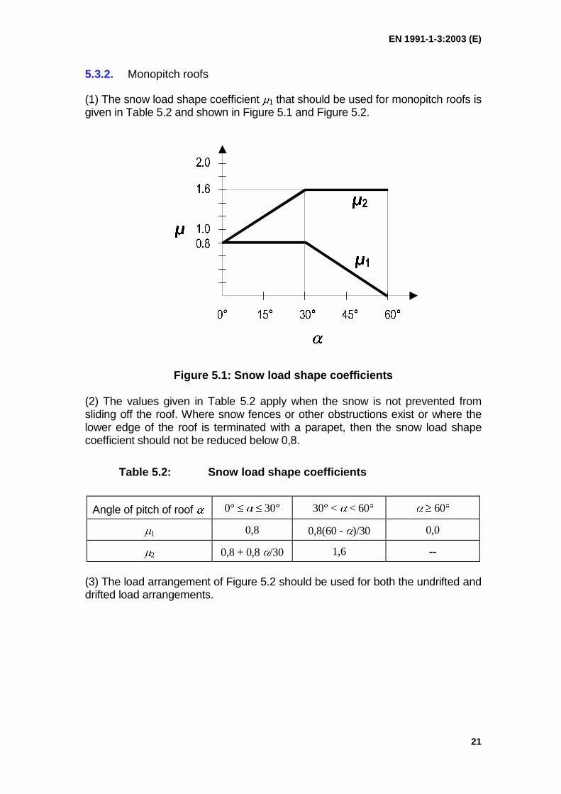
5.3.2. Monopitch roofs
(1) The snow load shape coefficient �1 that should be used for monopitch roofs isgiven in Table 5.2 and shown in Figure 5.1 and Figure 5.2.
���
���
�� ��� ��� �� ��
� ���
��
��
��
�� ��
Figure 5.1: Snow load shape coefficients
(2) The values given in Table 5.2 apply when the snow is not prevented fromsliding off the roof. Where snow fences or other obstructions exist or where thelower edge of the roof is terminated with a parapet, then the snow load shapecoefficient should not be reduced below 0,8.
Table 5.2: Snow load shape coefficients
Angle of pitch of roof � 0� � � � 30� 30� < � < 60� � � 60�
�1 0,8 0,8(60 - �)/30 0,0
�2 0,8 + 0,8 �/30 1,6 --
(3) The load arrangement of Figure 5.2 should be used for both the undrifted anddrifted load arrangements.
EN 1991-1-3:2003 (E)
22
��
��
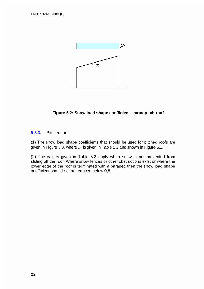
Figure 5.2: Snow load shape coefficient - monopitch roof
5.3.3. Pitched roofs
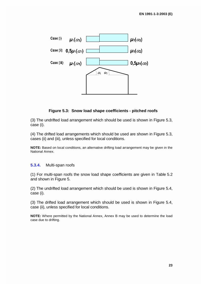
(1) The snow load shape coefficients that should be used for pitched roofs aregiven in Figure 5.3, where �1 is given in Table 5.2 and shown in Figure 5.1.
(2) The values given in Table 5.2 apply when snow is not prevented fromsliding off the roof. Where snow fences or other obstructions exist or where thelower edge of the roof is terminated with a parapet, then the snow load shapecoefficient should not be reduced below 0,8.
EN 1991-1-3:2003 (E)
23
����
������� �������
���������� �������
������� ����������
����
���� ���
���� ����
���� �����
Figure 5.3: Snow load shape coefficients - pitched roofs
(3) The undrifted load arrangement which should be used is shown in Figure 5.3,case (i).
(4) The drifted load arrangements which should be used are shown in Figure 5.3,cases (ii) and (iii), unless specified for local conditions.
NOTE: Based on local conditions, an alternative drifting load arrangement may be given in theNational Annex.
5.3.4. Multi-span roofs
(1) For multi-span roofs the snow load shape coefficients are given in Table 5.2and shown in Figure 5.
(2) The undrifted load arrangement which should be used is shown in Figure 5.4,case (i).
(3) The drifted load arrangement which should be used is shown in Figure 5.4,case (ii), unless specified for local conditions.
NOTE: Where permitted by the National Annex, Annex B may be used to determine the loadcase due to drifting.

EN 1991-1-3:2003 (E)
24
����
�������
���� ���� ����
������� �������
�������
������� �������
������ �� � ������� ����������
���� ���
���� ����
Figure 5.4: Snow load shape coefficients for multi-span roofs
(4) Special consideration should be given to the snow load shape coefficientsfor the design of multi-span roofs, where one or both sides of the valley have aslope greater than 60o.
NOTE: Guidance may be given in the National Annex.
5.3.5. Cylindrical roofs(1) The snow load shape coefficients that should be used for cylindrical roofs, inabsence of snow fences, are given in the following expressions (see also Figure5.6).
For � > 60�, �3 = 0 (5.4)For � � 60�, �3 = 0,2 + 10 h/b (5.5)
An upper value of �3 should be specified.
NOTE 1: The upper value of �3 may be specified in the National Annex. The recommendedupper value for �3 is 2,0 (see Figure 5.5).
� ��� ��� ��� ��� ���
��
��
� � �
���
�����
��
Figure 5.5: Recommended snow load shape coefficient for cylindrical roofs ofdiffering rise to span ratios (for �� �� 60°)

EN 1991-1-3:2003 (E)
25
NOTE 2: Rules for considering the effect of snow fences for snow loads on cylindrical roofsmay be given in the National Annex.
(2) The undrifted load arrangement which should be used is shown in Figure 5.6,case (i).
(3) The drifted load arrangement which should be used is shown in Figure 5.6,case (ii), unless specified for local conditions.
NOTE: Based on local conditions an alternative drifting load arrangement may be given in theNational Annex.
���
�����
������
��
�
��
���� ���
���� ����
��
ls/4
�
ls/4 ls/4 ls/4
Figure 5.6: Snow load shape coefficients for cylindrical roof
5.3.6. Roof abutting and close to taller construction works
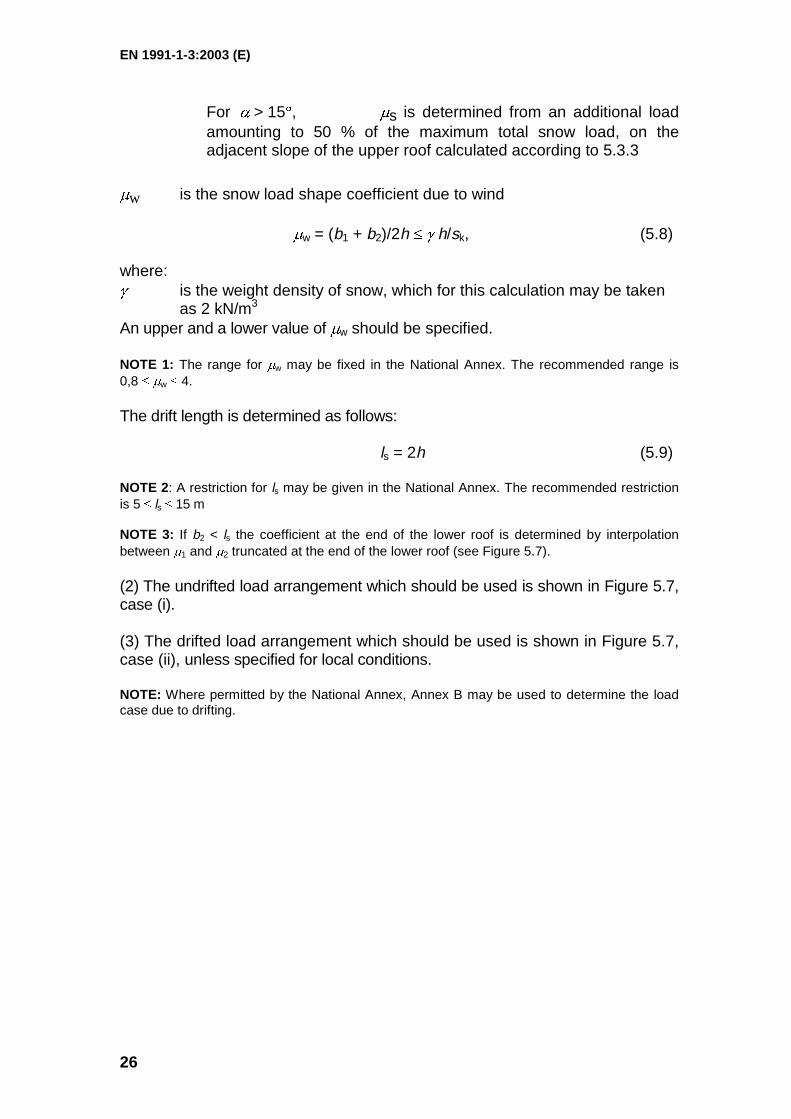
(1) The snow load shape coefficients that should be used for roofs abutting totaller construction works are given in the following expressions and shown inFigure 5.7.
�1 = 0,8 (assuming the lower roof is flat) (5.6)
�2 = �s + �w (5.7)
where:
�s is the snow load shape coefficient due to sliding of snow from theupper roof
For � � 15�, �s = 0,
EN 1991-1-3:2003 (E)
26
For � > 15�, �s is determined from an additional loadamounting to 50 % of the maximum total snow load, on theadjacent slope of the upper roof calculated according to 5.3.3
�w is the snow load shape coefficient due to wind
�w = (b1 + b2)/2h � � h/sk, (5.8)
where:� is the weight density of snow, which for this calculation may be taken
as 2 kN/m3
An upper and a lower value of �w should be specified.
NOTE 1: The range for �w may be fixed in the National Annex. The recommended range is0,8 � �w � 4.
The drift length is determined as follows:
ls = 2h (5.9)
NOTE 2: A restriction for ls may be given in the National Annex. The recommended restrictionis 5 � ls � 15 m
NOTE 3: If b2 < ls the coefficient at the end of the lower roof is determined by interpolationbetween �1 and �2 truncated at the end of the lower roof (see Figure 5.7).
(2) The undrifted load arrangement which should be used is shown in Figure 5.7,case (i).
(3) The drifted load arrangement which should be used is shown in Figure 5.7,case (ii), unless specified for local conditions.
NOTE: Where permitted by the National Annex, Annex B may be used to determine the loadcase due to drifting.
EN 1991-1-3:2003 (E)
27
��
��
l s
� �
��
�� ��
���� ��� ��
���� ����
�� l s
�� ��� ��
��
�� ��
���� ��� ��
���� ����
�
This case applies where ��� ��
Figure 5.7: Snow load shape coefficients for roofs abutting totaller construction works
EN 1991-1-3:2003 (E)
28
6. Section 6 Local effects
6.1. General
(1) This section gives forces to be applied for the local verifications of:– drifting at projections and obstructions;– the edge of the roof;– snow fences.
(2) The design situations to be considered are persistent/transient.
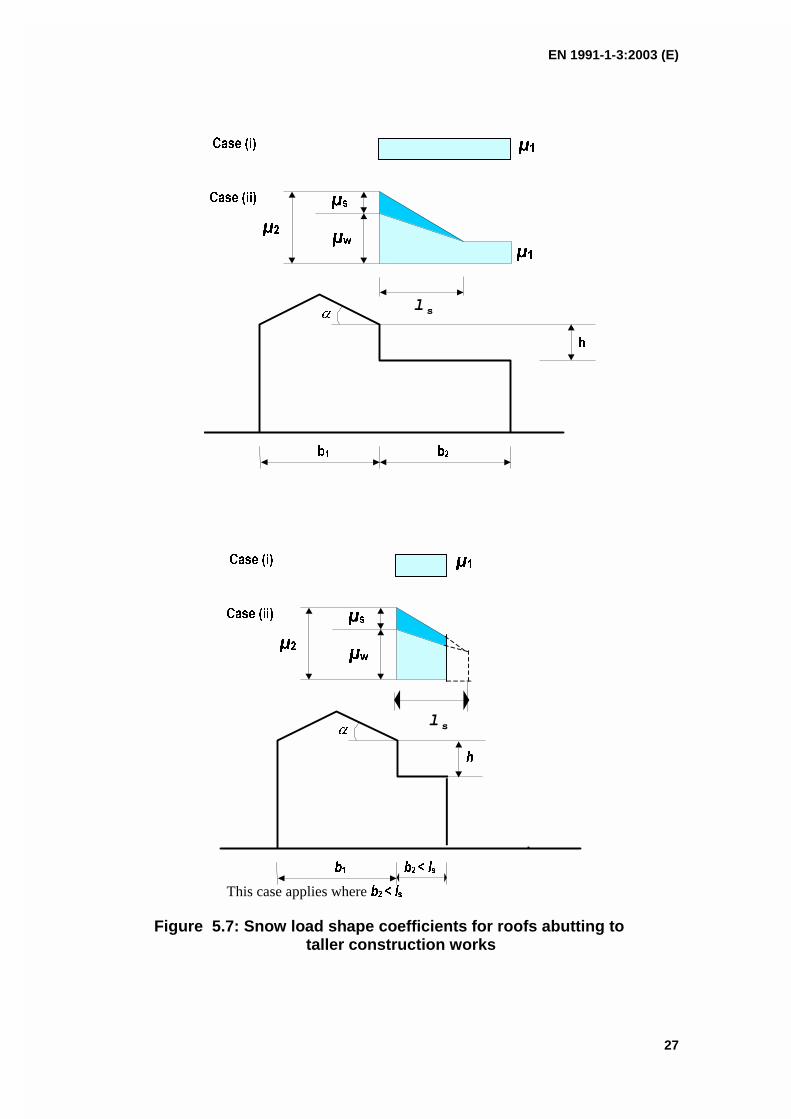
6.2. Drifting at projections and obstructions
(1) In windy conditions drifting of snow can occur on any roof which hasobstructions as these cause areas of aerodynamic shade in which snowaccumulates.
(2) The snow load shape coefficients and drift lengths for quasi-horizontal roofsshould be taken as follows (see Figure 6.1), unless specified for localconditions:
�1 = 0,8 �2 = � h/sk (6.1)
with the restriction: 0,8 � �2 � 2,0 (6.2)
where:
� is the weight density of snow, which for this calculation may betaken as 2 kN/m3
ls = 2h (6.3)
with the restriction: 5 � ls � 15 m
NOTE: Where permitted by the National Annex, Annex B may be used to determine the loadcase due to drifting.
EN 1991-1-3:2003 (E)
29
Figure 6.1: Snow load shape coefficients at projectionsand obstructions
6.3. Snow overhanging the edge of a roof
(1) Snow overhanging the edge of a roof should be considered.
NOTE: The National Annex may specify the conditions of use for this clause. It isrecommended that the clause is used for sites above 800 meters above sea level.
(2) The design of those parts of a roof cantilevered out beyond the walls shouldtake account of snow overhanging the edge of the roof, in addition to the loadon that part of the roof. The loads due to the overhang may be assumed to actat the edge of the roof and may be calculated as follows:
se = k s2 / � (6.4)
where:
se is snow load per metre length due to the overhang (see Figure 6.2)
s is the most onerous undrifted load case appropriate for the roofunder consideration (see 5.2)
� is the weight density of snow which for this calculation may betaken as 3 kN/m3
k is a coefficient to take account of the irregular shape of the snow
�
��
l s
��
l s
EN 1991-1-3:2003 (E)
30
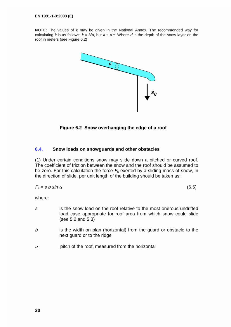
NOTE: The values of k may be given in the National Annex. The recommended way forcalculating k is as follows: k = 3/d, but k � d �. Where d is the depth of the snow layer on theroof in meters (see Figure 6.2)
� �
d
Figure 6.2 Snow overhanging the edge of a roof
6.4. Snow loads on snowguards and other obstacles
(1) Under certain conditions snow may slide down a pitched or curved roof.The coefficient of friction between the snow and the roof should be assumed tobe zero. For this calculation the force Fs exerted by a sliding mass of snow, inthe direction of slide, per unit length of the building should be taken as:
Fs = s b sin � (6.5)
where:
s is the snow load on the roof relative to the most onerous undriftedload case appropriate for roof area from which snow could slide(see 5.2 and 5.3)
b is the width on plan (horizontal) from the guard or obstacle to thenext guard or to the ridge
� pitch of the roof, measured from the horizontal

EN 1991-1-3:2003 (E)
31
ANNEX A(normative)
Design situations and load arrangements to be usedfor different locations
(1) Table A.1 summarises four cases A, B1, B2 and B3 (see 3.2, 3.3(1), 3.3(2)and 3.3(3) respectively) identifying the design situations and loadarrangements to be used for each individual case.

EN 1991-1-3:2003 (E)
32
Table A.1 Design Situations and load arrangements to be used for different locations
Normal Exceptional conditionsCase A Case B1 Case B2 Case B3No exceptional fallsNo exceptional drift
Exceptional fallsNo exceptional drift
No exceptional fallsExceptional drift
Exceptional fallsExceptional drift
3.2(1) 3.3(1) 3.3(2) 3.3(3)
Persistent/transient designsituation
[1] undrifted �i CeCt sk
[2] drifted �i CeCt sk
Persistent/transient designsituation
[1] undrifted �i CeCt sk
[2] drifted �i CeCt sk
Accidental design situation(where snow is the accidentalaction)
[3] undrifted �i CeCt Cesl sk
[4] drifted �i CeCt Cesl sk
Persistent/transient designsituation
[1] undrifted �i CeCt sk
[2] drifted �i CeCt sk (except forroof shapes in AnnexB)
Accidental design situation(where snow is the accidentalaction)
[3] drifted �i sk (for roof shapesin AnnexB)
Persistent/transient designsituation
[1] undrifted �i CeCt sk
[2] drifted �i CeCt sk (except forroof shapes in AnnexB)
Accidental design situation(where snow is the accidentalaction)
[3] undrifted �i CeCt Cesl sk
[4] drifted �i sk (for roof shapesin AnnexB)
NOTE 1: Exceptional conditions are defined according to the National Annex.
NOTE 2: For cases B1 and B3 the National Annex may define design situations which apply for the particular local effects described in section 6.

EN 1991-1-3:2003 (E)
33
ANNEX B(normative)
Snow load shape coefficients for exceptional snowdrifts
B1 Scope
(1) This annex gives snow shape coefficients to determine load arrangementsdue to exceptional snow drifts for the following types of roofs.a) Multi-span roofs;b) Roofs abutting and close to taller construction works;c) Roofs where drifting occurs at projections, obstructions and parapets.d) For all other load arrangements Section 5 and Section 6 should be used
as appropriate.
(2) When considering load cases using snow load shape coefficients obtainedfrom this Annex it should be assumed that they are exceptional snow driftloads and that there is no snow elsewhere on the roof.
(3) In some circumstances more than one drift load case may be applicable forthe same location on a roof in which case they should be treated asalternatives.
B2 Multi-span roofs
(1) The snow load shape coefficient for an exceptional snow drift that shouldbe used for valleys of multi-span roofs is given in Figure B1 and B2(2).
Figure B1: Shape coefficient and drift lengths for exceptional snow drifts– valleys of multi-span roofs
h
b2b1
b3
ls2ls1
�1
EN 1991-1-3:2003 (E)
34
(2) The shape coefficient given in Figure B1 is determined as the least valueof:
�1 = 2h/sk
�1 = 2b3/(ls1 + ls2)
�1 = 5
The drift lengths are determined as:
ls1 = b1 , ls2 = b2
(3) For roofs of more than two spans with approximately symmetrical anduniform geometry, b3 should be taken as the horizontal dimension of threeslopes (i.e. span x 1.5) and this snow load distribution should be consideredapplicable to every valley, although not necessarily simultaneously.
(4) Care should be taken when selecting b3 for roofs with non-uniformgeometry, significant differences in ridge height and/or span may act asobstructions to the free movement of snow across the roof and influence theamount of snow theoretically available to form the drift.
(5) Where simultaneous drifts in several valleys of a multi-span roof are beingconsidered in the design of a structure as a whole, a maximum limit on theamount of drifted snow on the roof should be applied. The total snow load permetre width in all the simultaneous drifts should not exceed the product of theground snow load and the length of the building perpendicular to the valleyridges.
NOTE: If the structure is susceptible to asymmetric loading, the design should also considerthe possibility of drifts of differing severity in the valleys.
B3 Roofs abutting and close to taller structures
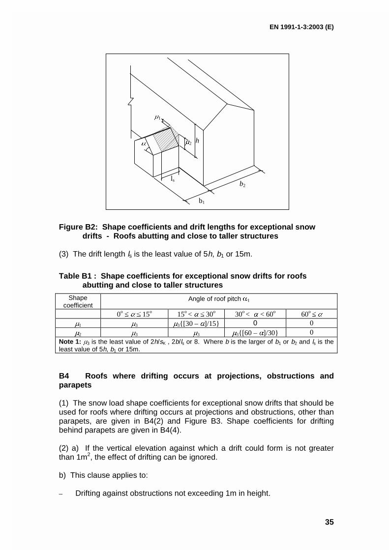
(1) The snow load shape coefficients for exceptional snow drifts that should beused for roofs abutting a taller construction work are given in Figure B2 andTable B1.
(2) The snow load case given in Figure B2 is also applicable for roofs close to,but not abutting, taller buildings, with the exception that it is only necessary toconsider the load actually on the lower roof, i.e. the load implied between thetwo buildings can be ignored.
NOTE: The effect of structures close to, but not abutting the lower roof will depend on the roofareas available from which snow can be blown into the drift and the difference in levels.However, as an approximate rule, it is only necessary to consider nearby structures when theyare less than 1,5m away.
EN 1991-1-3:2003 (E)
35
Figure B2: Shape coefficients and drift lengths for exceptional snowdrifts - Roofs abutting and close to taller structures
(3) The drift length ls is the least value of 5h, b1 or 15m.
Table B1 : Shape coefficients for exceptional snow drifts for roofsabutting and close to taller structures
Shapecoefficient
Angle of roof pitch �1
0o � � � 15o 15o < � � 30o 30o < � < 60o 60o � �
�1 �3 �3{[30 – �]/15} 0 0�2 �3 �3 �3{[60 – �]/30} 0
Note 1: �3 is the least value of 2h/sK , 2b/ls or 8. Where b is the larger of b1 or b2 and ls is theleast value of 5h, b1 or 15m.
B4 Roofs where drifting occurs at projections, obstructions andparapets
(1) The snow load shape coefficients for exceptional snow drifts that should beused for roofs where drifting occurs at projections and obstructions, other thanparapets, are given in B4(2) and Figure B3. Shape coefficients for driftingbehind parapets are given in B4(4).
(2) a) If the vertical elevation against which a drift could form is not greaterthan 1m2, the effect of drifting can be ignored.
b) This clause applies to:
– Drifting against obstructions not exceeding 1m in height.
ls
�1
�2�h
b1
b2
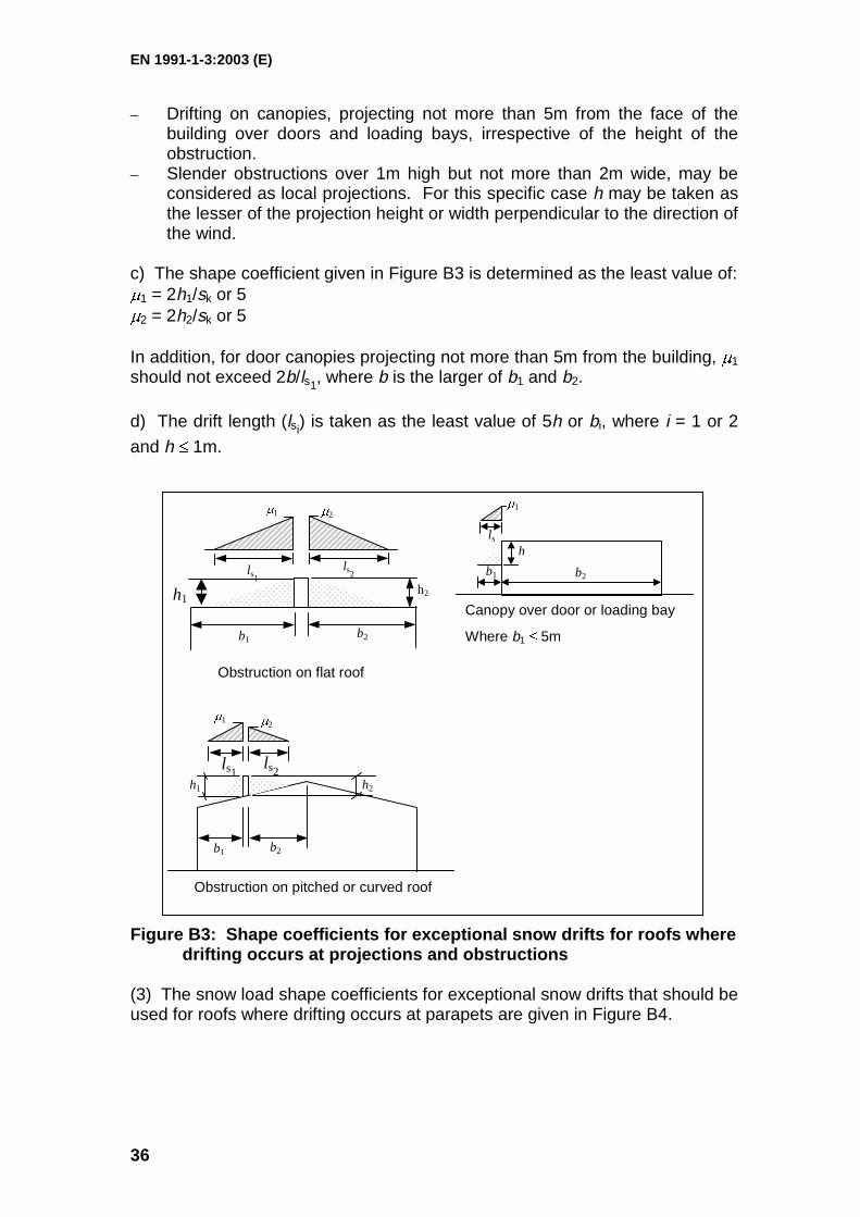
EN 1991-1-3:2003 (E)
36
– Drifting on canopies, projecting not more than 5m from the face of thebuilding over doors and loading bays, irrespective of the height of theobstruction.
– Slender obstructions over 1m high but not more than 2m wide, may beconsidered as local projections. For this specific case h may be taken asthe lesser of the projection height or width perpendicular to the direction ofthe wind.
c) The shape coefficient given in Figure B3 is determined as the least value of:�1 = 2h1/sk or 5�2 = 2h2/sk or 5
In addition, for door canopies projecting not more than 5m from the building, �1
should not exceed 2b/ls1, where b is the larger of b1 and b2.
d) The drift length (lsi) is taken as the least value of 5h or bi, where i = 1 or 2
and h � 1m.
Figure B3: Shape coefficients for exceptional snow drifts for roofs wheredrifting occurs at projections and obstructions
(3) The snow load shape coefficients for exceptional snow drifts that should beused for roofs where drifting occurs at parapets are given in Figure B4.
h1
Obstruction on flat roof
�2
ls2ls1
�1
h2
b2b1
b1 b2
h2h1
ls1 ls2
�1 �2
Obstruction on pitched or curved roof
b1 b2
lsh
�1
Canopy over door or loading bay
Where b1 � 5m
EN 1991-1-3:2003 (E)
37
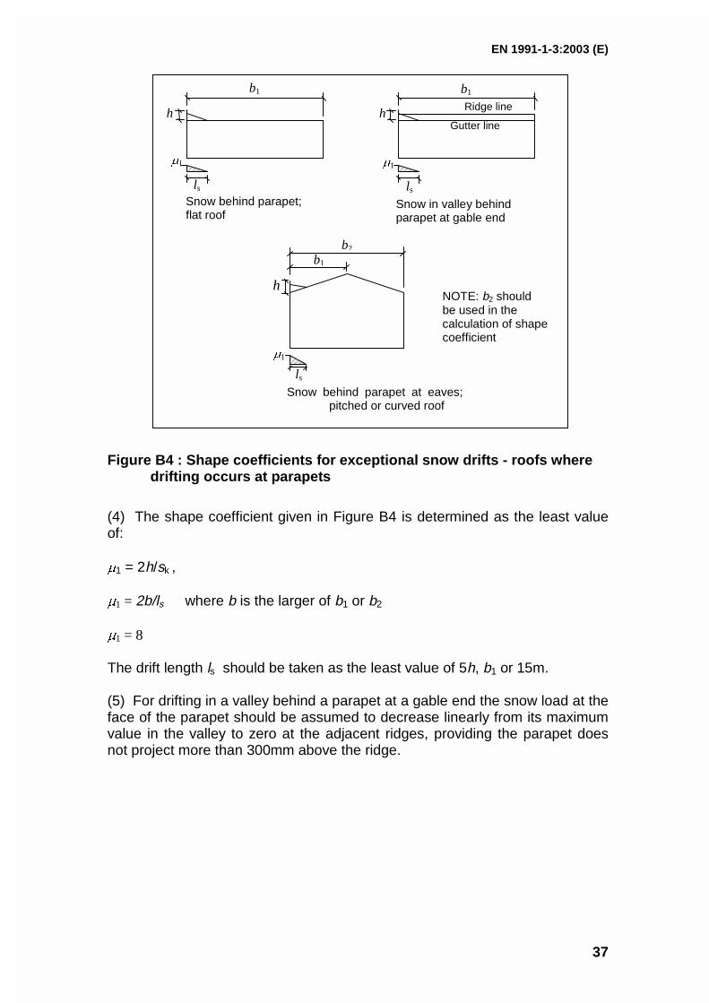
Figure B4 : Shape coefficients for exceptional snow drifts - roofs wheredrifting occurs at parapets
(4) The shape coefficient given in Figure B4 is determined as the least valueof:
�1 = 2h/sk ,
�1 = 2b/ls where b is the larger of b1 or b2
�1 = 8
The drift length ls should be taken as the least value of 5h, b1 or 15m.
(5) For drifting in a valley behind a parapet at a gable end the snow load at theface of the parapet should be assumed to decrease linearly from its maximumvalue in the valley to zero at the adjacent ridges, providing the parapet doesnot project more than 300mm above the ridge.
h
b1
ls
�1
Snow behind parapet;flat roof
h
lsSnow in valley behindparapet at gable end
b1
�1
Ridge line
Gutter line
b2
�1
b1
lsSnow behind parapet at eaves;
pitched or curved roof
NOTE: b2 shouldbe used in thecalculation of shapecoefficient
h
EN 1991-1-3:2003 (E)
38
ANNEX C(informative)
European Ground Snow Load Maps
(1) This Annex presents the European snow maps which are the result ofscientific work carried out under contract to DGIII/D-35 of the EuropeanCommission, by a specifically formed research Group.
NOTE: The snow maps supplied by CEN members who were not directly part of the ResearchGroup have been included in this Annex in clauses C(5) Czech Republic, C(6) Iceland andC(7) Poland.
(2) The objectives of this Annex, defined in 1.1(5), are:– to help National Competent Authorities to redraft their national maps;– to establish harmonised procedures to produce the maps.
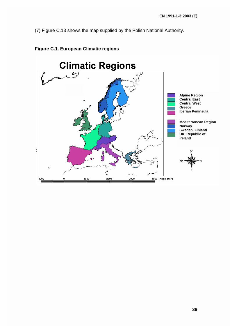
This will eliminate or reduce the inconsistencies of snow load values in CENmember states and at borderlines between countries.
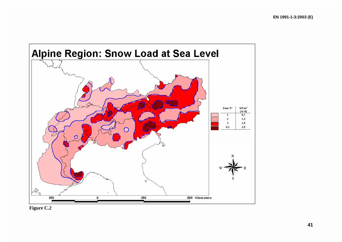
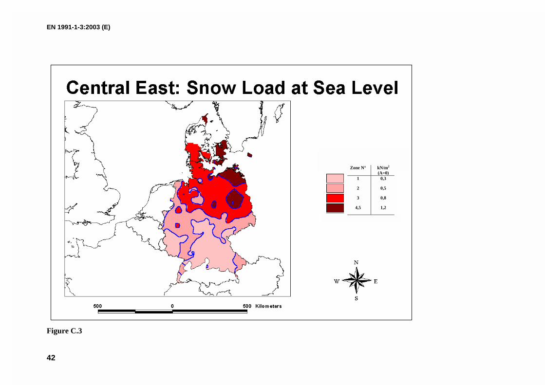
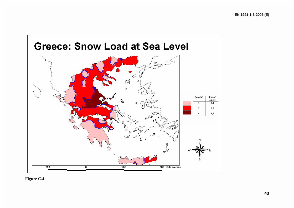
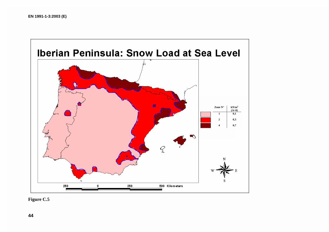
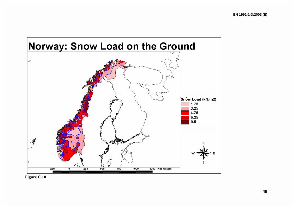
(3) The European snow map developed by the Research Group are dividedinto 9 different homogeneous climatic regions, as shown in Figures C.1 toC.10.
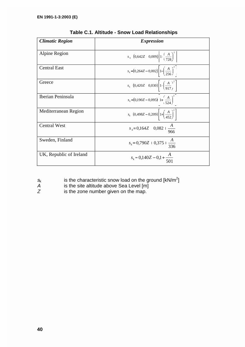
(4) In each climatic region a given load-altitude correlation formula applies andthis is given in Table C.1.Different zones are defined for each climatic region. Each zone is given a Zonenumber Z, which is used in the load altitude correction formula.Among the research Group members only for Norway the map gives directlysnow load on the ground at different locations.The characteristic values of ground snow loads given are referred to meanrecurrence interval (MRI) equal to 50 years.
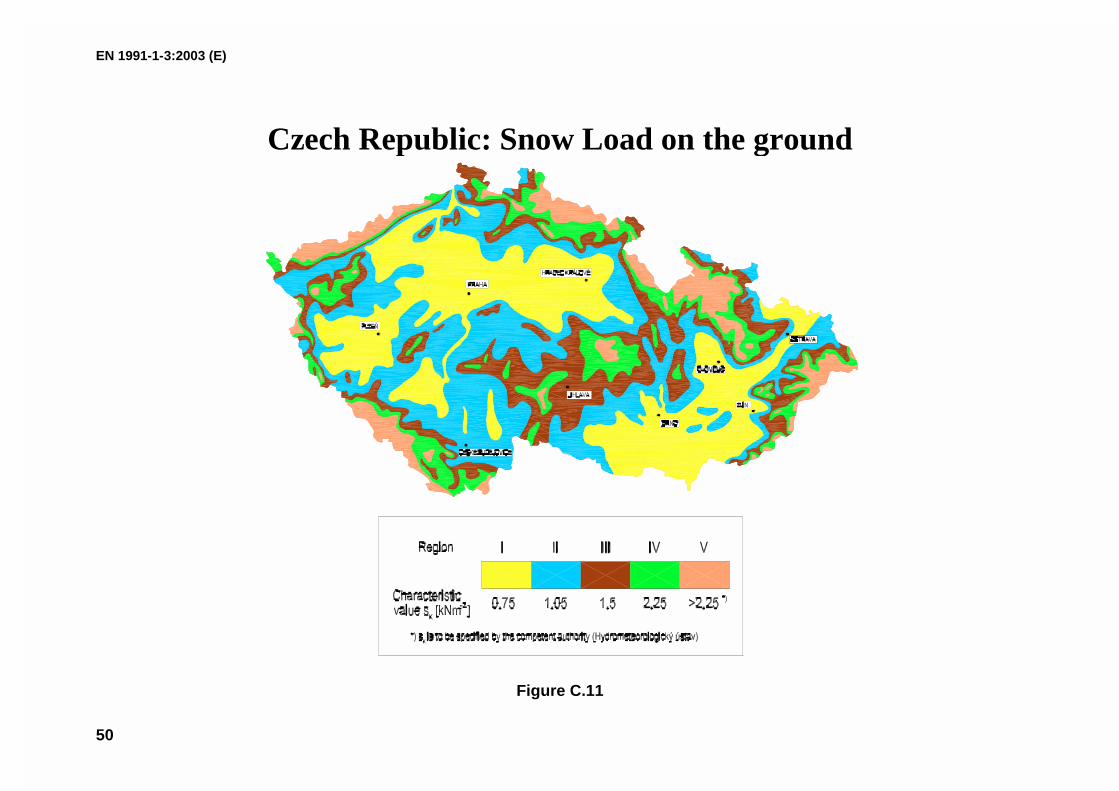
(5) Figure C.11 shows the map supplied by the Czech National Authority.
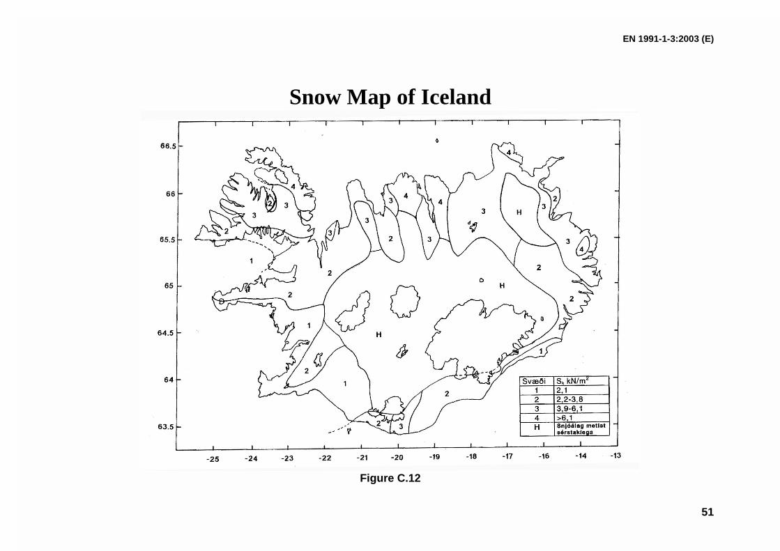
(6) Figure C.12 shows the map supplied by the Icelandic National Authority.
5 Results are included in the following documents, both of them are available at the
Commission of the European Communities DG III - D-3 Industry, Rue de la Loi, 200 B -1049 Brussels, or at the Università degli Studi di Pisa Dipartimento di Ingegneria Strutturale,Via Diotisalvi, 2, 56100 Pisa (IT).1. Phase 1 Final Report to the European Commission, Scientific Support Activity in theField of Structural Stability of Civil Engineering Works: Snow Loads, Department ofStructural Engineering, University of Pisa, March 1998.2. Phase 2 Final Report to the European Commission, Scientific Support Activity in theField of Structural Stability of Civil Engineering Works: Snow Loads, Department ofStructural Engineering, University of Pisa, September 1999.
EN 1991-1-3:2003 (E)
39
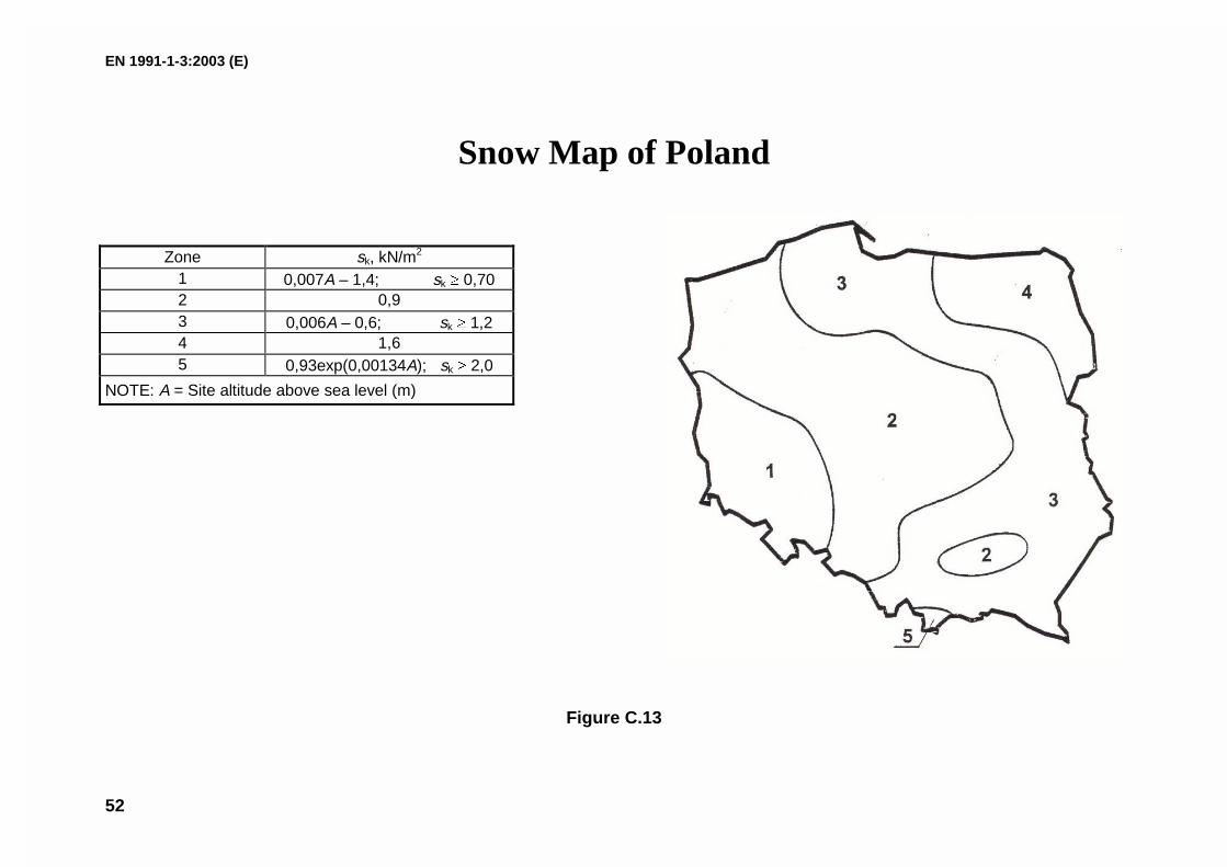
(7) Figure C.13 shows the map supplied by the Polish National Authority.
Figure C.1. European Climatic regions
Alpine RegionCentral EastCentral WestGreeceIberian Peninsula
Mediterranean RegionNorwaySweden, FinlandUK, Republic ofIreland
EN 1991-1-3:2003 (E)
40
Table C.1. Altitude - Snow Load Relationships
Climatic Region Expression
Alpine Region� �
���
�
���
���
�
� �
2
7281009,0642,0
AZsk
Central East� �
���
�
���
���
�
� ��
2
2561002,0264,0
AZsk
Greece� �
���
�
���
���
�
� ��
2
9171030,0420,0
AZsk
Iberian Peninsula� �
���
�
���
���
�
� ��
2
5241095,0190,0
AZsk
Mediterranean Region� �
���
�
���
���
�
� ��
2
4521209,0498,0
AZsk
Central West966
082,0164,0A
Zsk ���
Sweden, Finland336
375,0790,0A
Zsk ���
UK, Republic of Ireland501
1,0140,0A
Zsk ���
sk is the characteristic snow load on the ground [kN/m2]A is the site altitude above Sea Level [m]Z is the zone number given on the map.
EN 1991-1-3:2003 (E)
41
Figure C.2
Zone N° kN/m2
(A=0)1 0,72 1,33 1,9
4,5 2,9
EN 1991-1-3:2003 (E)
42
Figure C.3
Zone N° kN/m2
(A=0)1 0,3
2 0,5
3 0,8
4,5 1,2
EN 1991-1-3:2003 (E)
43
Figure C.4
Zone N° kN/m2
(A=0)1 0,4
2 0,8
4 1,7
EN 1991-1-3:2003 (E)
44
Figure C.5
Zone N° kN/m2
(A=0)1 0,1
2 0,3
4 0,7
EN 1991-1-3:2003 (E)
45
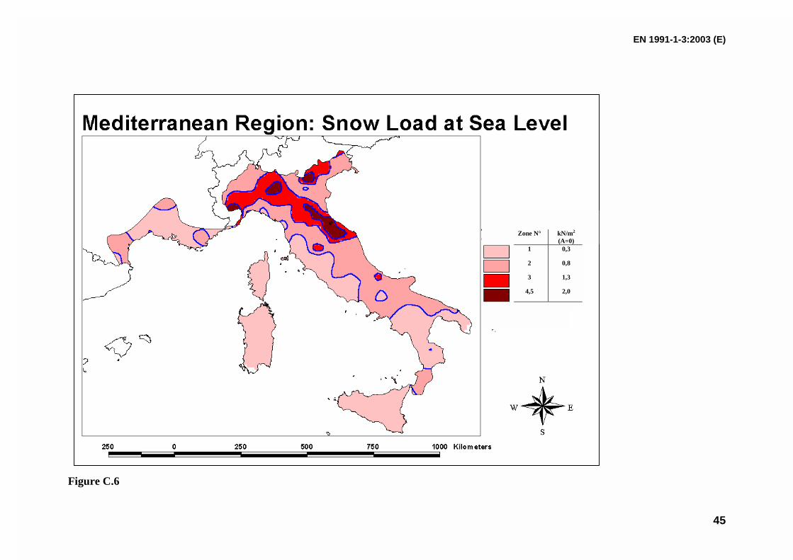
Figure C.6
Zone N° kN/m2
(A=0)1 0,3
2 0,8
3 1,3
4,5 2,0
EN 1991-1-3:2003 (E)
46
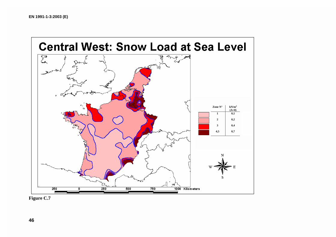
Figure C.7
Zone N° kN/m2
(A=0)1 0,1
2 0,2
3 0,4
4,5 0,7
EN 1991-1-3:2003 (E)
47
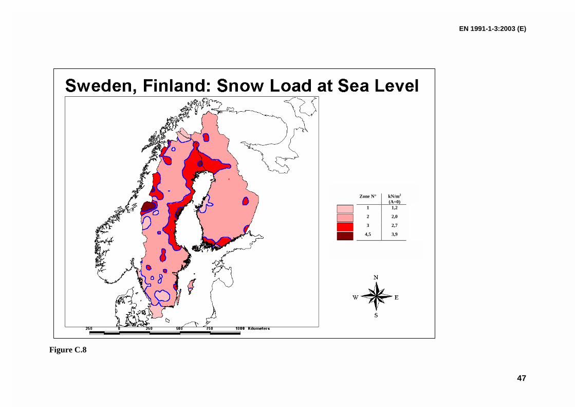
Figure C.8
Zone N° kN/m2
(A=0)1 1,2
2 2,0
3 2,7
4,5 3,9
EN 1991-1-3:2003 (E)
48
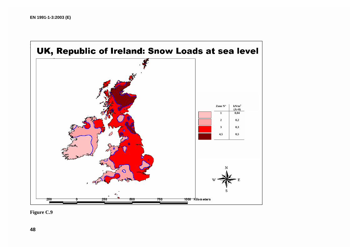
Figure C.9
Figure C.9
Zone N° kN/m2
(A=0)1 0,04
2 0,2
3 0,3
4,5 0,5
��� ������ � ������� �� � � ��� �� ��� ���
EN 1991-1-3:2003 (E)
49
Figure C.10
EN 1991-1-3:2003 (E)
50
Czech Republic: Snow Load on the ground
Figure C.11
EN 1991-1-3:2003 (E)
51
Snow Map of Iceland
Figure C.12
EN 1991-1-3:2003 (E)
52
Snow Map of Poland
Zone sk, kN/m2
1 0,007A – 1,4; sk � 0,702 0,93 0,006A – 0,6; sk � 1,24 1,65 0,93exp(0,00134A); sk � 2,0
NOTE: A = Site altitude above sea level (m)
Figure C.13
EN 1991-1-3:2003 (E)
53
ANNEX D(informative)
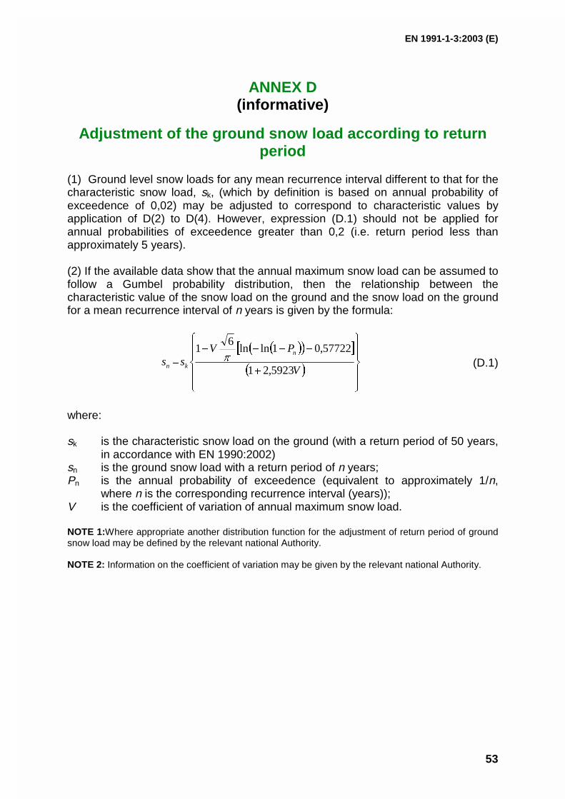
Adjustment of the ground snow load according to returnperiod
(1) Ground level snow loads for any mean recurrence interval different to that for thecharacteristic snow load, sk, (which by definition is based on annual probability ofexceedence of 0,02) may be adjusted to correspond to characteristic values byapplication of D(2) to D(4). However, expression (D.1) should not be applied forannual probabilities of exceedence greater than 0,2 (i.e. return period less thanapproximately 5 years).
(2) If the available data show that the annual maximum snow load can be assumed tofollow a Gumbel probability distribution, then the relationship between thecharacteristic value of the snow load on the ground and the snow load on the groundfor a mean recurrence interval of n years is given by the formula:
(D.1)
where:
sk is the characteristic snow load on the ground (with a return period of 50 years,in accordance with EN 1990:2002)
sn is the ground snow load with a return period of n years;Pn is the annual probability of exceedence (equivalent to approximately 1/n,
where n is the corresponding recurrence interval (years));V is the coefficient of variation of annual maximum snow load.
NOTE 1:Where appropriate another distribution function for the adjustment of return period of groundsnow load may be defined by the relevant national Authority.
NOTE 2: Information on the coefficient of variation may be given by the relevant national Authority.
� �� �� �
� ����
���
�
���
���
�
�
�
V
PVss
n
kn 5923,21
57722,01lnln6
1�
EN 1991-1-3:2003 (E)
54
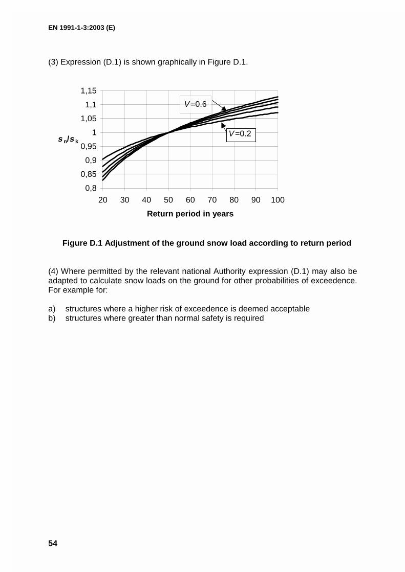
(3) Expression (D.1) is shown graphically in Figure D.1.
0,8
0,85
0,9
0,95
1
1,05
1,1
1,15
20 30 40 50 60 70 80 90 100
Return period in years
s n/s k
V =0.6
V =0.2
Figure D.1 Adjustment of the ground snow load according to return period
(4) Where permitted by the relevant national Authority expression (D.1) may also beadapted to calculate snow loads on the ground for other probabilities of exceedence.For example for:
a) structures where a higher risk of exceedence is deemed acceptableb) structures where greater than normal safety is required

EN 1991-1-3:2003 (E)
55
ANNEX E(informative)
Bulk weight density of snow
(1) The bulk weight density of snow varies. In general it increases with the duration of thesnow cover and depends on the site location, climate and altitude.
(2) Except where specified in Sections 1 to 6 indicative values for the mean bulk weightdensity of snow on the ground given in Table E.1 may be used.
Table E.1: Mean bulk weight density of snow
Type of snow Bulk weight density [kN/m3]
Fresh 1,0
Settled (several hours or days after its fall) 2,0
Old (several weeks or months after its fall) 2,5 - 3,5
Wet 4,0

EN 1991-1-3:2003 (E)
56
Bibliography
ISO 4355 Bases for design of structures – Determination of snowloads on roofs
ISO 3898 Bases for design of structures - Notations – General symbols