Embed Size (px)
Citation preview
ABB machinery drives
SupplementACS355 high speed program (+N826)
List of related manuals
You can find manuals and other product documents in PDF format on the Internet. See section Document library on the Internet on the inside of the back cover. For manuals not available in the Document library, contact your local ABB representative.
Drive manuals and guides Code (English)ACS355 user’s manual 3AUA0000066143ACS355 drives with IP66/67 / UL Type 4x enclosure supplement
3AUA0000066066
ACS355 quick installation guide 3AUA0000092940ACS355 common DC application guide 3AUA0000070130ACS355 enhanced sequence program (+N830) Supplement
3AXD50000017465
ACS355 high speed program (+N826) Supplement 3AXD50000017574Option manuals and guidesFCAN-01 CANopen adapter module user’s manual 3AFE68615500FDNA-01 DeviceNet adapter module user’s manual 3AFE68573360FECA-01 EtherCAT® adapter module user’s manual 3AUA0000068940FENA-01/-11 Ethernet adapter module user's manual 3AUA0000093568FLON-01 LONWORKS® adapter module user’s manual 3AUA0000041017FMBA-01 Modbus adapter module user’s manual 3AFE68586704FPBA-01 PROFIBUS DP adapter module user’s manual 3AFE68573271FRSA-00 RS-485 adapter board user’s manual 3AFE68640300MFDT-01 FlashDrop user’s manual 3AFE68591074MPOT-01 potentiometer module instructions for installation and use
3AFE68591082
MREL-01 output relay module user’s manual 3AUA0000035974MTAC-01 pulse encoder interface module user’s manual 3AFE68591091MUL1-R1 installation instructions for ACS150, ACS310, ACS320, ACS350 and ACS355
3AFE68642868
MUL1-R3 installation instructions for ACS310, ACS320, ACS350 and ACS355
3AFE68643147
MUL1-R4 installation instructions for ACS310, ACS320, ACS350 and ACS355
3AUA0000025916
SREA-01 Ethernet adapter module quick start-up guide 3AUA0000042902SREA-01 Ethernet adapter module user’s manual 3AUA0000042896ACS355 and AC500-eCo application guide 2CDC125152M0201AC500-eCo PLC and ACS355 quick installation guide 2CDC125145M0201
Maintenance manuals and guidesGuide for capacitor reforming in ACS50, ACS55, ACS150, ACS310, ACS350, ACS355, ACS550, ACH550 and R1-R4 OINT/SINT boards
3AFE68735190
Supplement
ACS355 high speed program (+N826)
Table of contents
3AXD50000017574 Rev AEN
EFFECTIVE: 2014-07-09 2014 ABB Oy. All Rights Reserved.

1
Table of contents
1. Introduction to the supplement
What this chapter contains . . . . . . . . . . . . . . . . . . . . . . . . . . . . . . . . . . . . . . . . . . . . . . . . . . . . 7Safety . . . . . . . . . . . . . . . . . . . . . . . . . . . . . . . . . . . . . . . . . . . . . . . . . . . . . . . . . . . . . . . . . . . . 7Scope . . . . . . . . . . . . . . . . . . . . . . . . . . . . . . . . . . . . . . . . . . . . . . . . . . . . . . . . . . . . . . . . . . . . 7Applicability . . . . . . . . . . . . . . . . . . . . . . . . . . . . . . . . . . . . . . . . . . . . . . . . . . . . . . . . . . . . . . . . 8Target audience . . . . . . . . . . . . . . . . . . . . . . . . . . . . . . . . . . . . . . . . . . . . . . . . . . . . . . . . . . . . . 8Purpose of the manual . . . . . . . . . . . . . . . . . . . . . . . . . . . . . . . . . . . . . . . . . . . . . . . . . . . . . . . 8Contents of this supplement . . . . . . . . . . . . . . . . . . . . . . . . . . . . . . . . . . . . . . . . . . . . . . . . . . . 9Related documents . . . . . . . . . . . . . . . . . . . . . . . . . . . . . . . . . . . . . . . . . . . . . . . . . . . . . . . . . . 9
2. Program features
What this chapter contains . . . . . . . . . . . . . . . . . . . . . . . . . . . . . . . . . . . . . . . . . . . . . . . . . . . 11Drive selection tables . . . . . . . . . . . . . . . . . . . . . . . . . . . . . . . . . . . . . . . . . . . . . . . . . . . . . . . 11Fault reaction for EM STOP . . . . . . . . . . . . . . . . . . . . . . . . . . . . . . . . . . . . . . . . . . . . . . . . . . 12
Settings . . . . . . . . . . . . . . . . . . . . . . . . . . . . . . . . . . . . . . . . . . . . . . . . . . . . . . . . . . . . . . . 12Fault reaction for Power loss . . . . . . . . . . . . . . . . . . . . . . . . . . . . . . . . . . . . . . . . . . . . . . . . . . 13
Settings . . . . . . . . . . . . . . . . . . . . . . . . . . . . . . . . . . . . . . . . . . . . . . . . . . . . . . . . . . . . . . . 13Smooth start ramp . . . . . . . . . . . . . . . . . . . . . . . . . . . . . . . . . . . . . . . . . . . . . . . . . . . . . . . . . . 13
Settings . . . . . . . . . . . . . . . . . . . . . . . . . . . . . . . . . . . . . . . . . . . . . . . . . . . . . . . . . . . . . . . 13Start enable . . . . . . . . . . . . . . . . . . . . . . . . . . . . . . . . . . . . . . . . . . . . . . . . . . . . . . . . . . . . . . . 13
Settings . . . . . . . . . . . . . . . . . . . . . . . . . . . . . . . . . . . . . . . . . . . . . . . . . . . . . . . . . . . . . . . 13Fast user set change . . . . . . . . . . . . . . . . . . . . . . . . . . . . . . . . . . . . . . . . . . . . . . . . . . . . . . . . 14
Settings . . . . . . . . . . . . . . . . . . . . . . . . . . . . . . . . . . . . . . . . . . . . . . . . . . . . . . . . . . . . . . . 14 . . . . . . . . . . . . . . . . . . . . . . . . . . . . . . . . . . . . . . . . . . . . . . . . . . . . . . . . . . . . . . . . . . . . . . . . . 14
3. Actual signals and parameters
What this chapter contains . . . . . . . . . . . . . . . . . . . . . . . . . . . . . . . . . . . . . . . . . . . . . . . . . . . 15Actual signals . . . . . . . . . . . . . . . . . . . . . . . . . . . . . . . . . . . . . . . . . . . . . . . . . . . . . . . . . . . . . 16Parameters . . . . . . . . . . . . . . . . . . . . . . . . . . . . . . . . . . . . . . . . . . . . . . . . . . . . . . . . . . . . . . . 17
Further information
Product and service inquiries . . . . . . . . . . . . . . . . . . . . . . . . . . . . . . . . . . . . . . . . . . . . . . . . . 27Product training . . . . . . . . . . . . . . . . . . . . . . . . . . . . . . . . . . . . . . . . . . . . . . . . . . . . . . . . . . . . 27Providing feedback on ABB Drives manuals . . . . . . . . . . . . . . . . . . . . . . . . . . . . . . . . . . . . . . 27Document library on the Internet . . . . . . . . . . . . . . . . . . . . . . . . . . . . . . . . . . . . . . . . . . . . . . . 27

2
Introduction to the supplement 7
1Introduction to the supplement
What this chapter contains
The chapter describes safety issues, scope of this supplement, applicability, target audience and purpose of this supplement. It describes the contents of this supplement and refers to a list of related manuals for more information.
Safety
Safety related instructions please refer to ACS355 user’s manual (3AUA0000066143 [English]). The safety instructions must be followed when installing, operating and servicing the drive. Please study the complete safety instructions carefully.
Scope
This document is supplement of ACS355 user’s manual (3AUA0000066143 [English]). This supplement covers all differences between high speed program and ACS355 standard firmware. Only the high speed program contents are given in each chapter of this supplement.
8 Introduction to the supplement
Following chapters please refer to ACS355 user’s manual (3AUA0000066143 [English]):
• Operation principle and hardware description
• Mechanical installation
• Planning the electrical installation
• Electrical installation
• Installation checklist
• Control panels
• Application macros
• Startup, control with I/O and ID run
• Fieldbus control with fieldbus adapter
• Fault tracing
• Maintenance and hardware diagnostics
• Technical data
• Appendixes
Applicability
The manual is applicable to the ACS355 high speed program firmware version 6303 or later. See parameter 3301 FIRMWARE. Option code +N826 in the drive type code shows that the drive has the high speed program installed.
Target audience
This supplement is intended for people who work with ACS355 high speed program. The reader of this supplement is expected to know the fundamentals of electricity, wiring, electrical components and electrical schematic symbols.
Purpose of the manual
This manual provides information needed for commissioning, operating and maintaining the ACS355 high speed program.
Introduction to the supplement 9
Contents of this supplement
The supplement consists of the following chapters:
• Introduction to the supplement (this chapter, page 7) describes safety issues, scope of supplement, applicability, target audience and purpose of this manual.
• Program features (page 11) describes program features. There are also lists of related user settings in each section.
• Actual signals and parameters (page 15) describes the actual signals and parameters related to high speed program and gives the fieldbus equivalent values for each signal/parameter.
• Further information (inside of the back cover) tells how to make product and service inquiries, get information on product training, provide feedback on ABB Drives manuals and how to find documents on the Internet.
Related documents
See List of related manuals on page 2 (inside of the front cover).

10 Introduction to the supplement
Program features 11
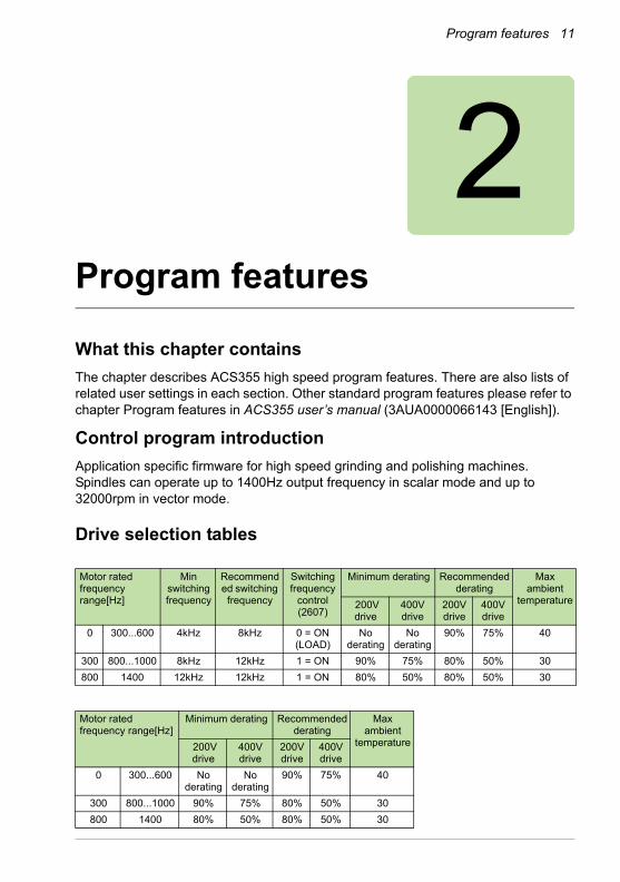
2Program features
What this chapter contains
The chapter describes ACS355 high speed program features. There are also lists of related user settings in each section. Other standard program features please refer to chapter Program features in ACS355 user’s manual (3AUA0000066143 [English]).
Control program introduction
Application specific firmware for high speed grinding and polishing machines. Spindles can operate up to 1400Hz output frequency in scalar mode and up to 32000rpm in vector mode.
Drive selection tables
Motor rated frequency range[Hz]
Min switching frequency
Recommended switching frequency
Switching frequency
control (2607)
Minimum derating Recommended derating
Max ambient
temperature 200V drive
400V drive
200V drive
400V drive
0 300...600 4kHz 8kHz 0 = ON (LOAD)
No derating
No derating
90% 75% 40
300 800...1000 8kHz 12kHz 1 = ON 90% 75% 80% 50% 30
800 1400 12kHz 12kHz 1 = ON 80% 50% 80% 50% 30
Motor rated frequency range[Hz]
Minimum derating Recommended derating
Max ambient
temperature 200V drive
400V drive
200V drive
400V drive
0 300...600 No derating
No derating
90% 75% 40
300 800...1000 90% 75% 80% 50% 30
800 1400 80% 50% 80% 50% 30
12 Program features
Note: These derating rules do not consider R0 frame.Please check the user’s manual for derating the R0 frame size.
Fault reaction for EM STOP
Emergency ramp stop in case of non critical faults and 500ms delayed fault for under voltage controller. Especially meant for blackouts. Spindle can keep on coasting for an hour in worst case.
• New parameter 30.29 added which enables emergency ramp stop when drive faults:
- 30.29 = 0 Fault reaction same as in standard FW.
- 30.29 = 1 Drive makes ramp stop during fault (except HW critical faults).
• Drive makes an emergency ramp stop when fault occurs using the emergency ramp stop deceleration time (par. 22.08).
• Hardware critical faults (“ OVERCURRENT ”, “ DC OVERVOLT ” and “SHORT CIRC”) will still make a coast stop in order to protect the drive. When hardware critical faults occur among several other faults, the drive will make a coast stop.
• “SAFE TORQUE OFF”, “STO1 LOST” and “STO2 LOST” faults will behave the same way as hardware critical faults since it is not possible to drive the motor anyway.
Related parameters are listed in the table below:
Settings
Parameter Additional information
2208 EMERG DEC TIME Time within which the drive is stopped if an
emergency stop is activated.
3029 FAULT RAMP STOP Enables emergency ramp stop when drive faults
Program features 13
Fault reaction for Power loss
When 20.06 UNDERVOLT CTRL = ENABLE(TIME) and 30.29 = ENABLE (fault ramp stop enabled) then drive faults after being in under-voltage control for 500ms. Fault will also trigger an emergency ramp stop.
Related parameters are listed in the table below:
Settings
Smooth start ramp
For PM motor there is possibility for different ramping during the smooth start period. This function can ensure succesful start of PM motor in case of high inertia and encoderless operation.
When option “SMOOTH START”(11) of parameter 22.01 “ACC/DEC 1/2 SEL” is selected, then ramp 2 is used while smooth start is active and ramp 1 when smooth start is not active.
Related parameters are listed in the table below:
Settings
Start enable
When start enable 1 or 2 is lost while drive is running, then drive will make the stop set by par. 21.02 STOP FUNCTION.
Related parameters are listed in the table below:
Settings
Parameter Additional information
2006 UNDERVOLT CTRL Activates or deactivates the undervoltage control of the intermediate DC link.
3029 FAULT RAMP STOP Enables emergency ramp stop when drive faults
Parameter Additional information
2201 ACC/DEC 1/2 SEL Source from which the drive reads the signal that selects between the two ramp pairs.
Parameter Additional information
1608 START ENABLE 1 Selects the source for the Start enable 1 signal.
1609 START ENABLE 2 Selects the source for the Start enable 2 signal.
2102 STOP FUNCTION Selects the motor stop function.
14 Program features
Fast user set change
Totally 6 user sets and possibility change quickly between them. User can switch from different ramp and controller values for different tools in case machine has several tools.
Pararameter 0186 ACTIVE MACRO – shows which user set was last loaded, updated after start inhibits are removed. Parameter 0186 changes to 0, when user set load starts and drive is ready to start when parameter 0186 changes to loaded user set value.
Related parameters are listed in the table below:
Settings
Parameter Additional information
0186 ACTIVE MACRO Shows which user macro is actively loaded.
1605 USER PAR SET CHG Enables the change of the User parameter set through a digital input.
1614 LOAD USER SET Selects which user set will be loaded.
1615 SAVE USER SET Selects which user set will be saved.
9902 APPLIC MACRO Selects the application macro.
Actual signals and parameters 15
3Actual signals and parameters
What this chapter contains
The chapter describes the actual signals and parameters related to high speed program and gives the fieldbus equivalent values for each signal/parameter.
Terms and abbreviations
Note: More information about drive parameters please refer to the section Actual signal and parameters in ACS355 User’s manual (3AUA0000066143 [English]).
Term Definition
Actual signal Sequence program related signals measured or calculated by the drive. Can be monitored by the user. No user setting possible.
Def Parameter default value
Parameter A user-adjustable sequence program operation instruction of the drive. Note: Parameter selections are shown on the basic control panel as integer values. Eg parameter 1001 EXT1 COMMANDS selection COMM is shown as value 10 (which is equal to the fieldbus equivalent FbEq).
FbEq Fieldbus equivalent: The scaling between the value and the integer used in serial communication.
16 Actual signals and parameters
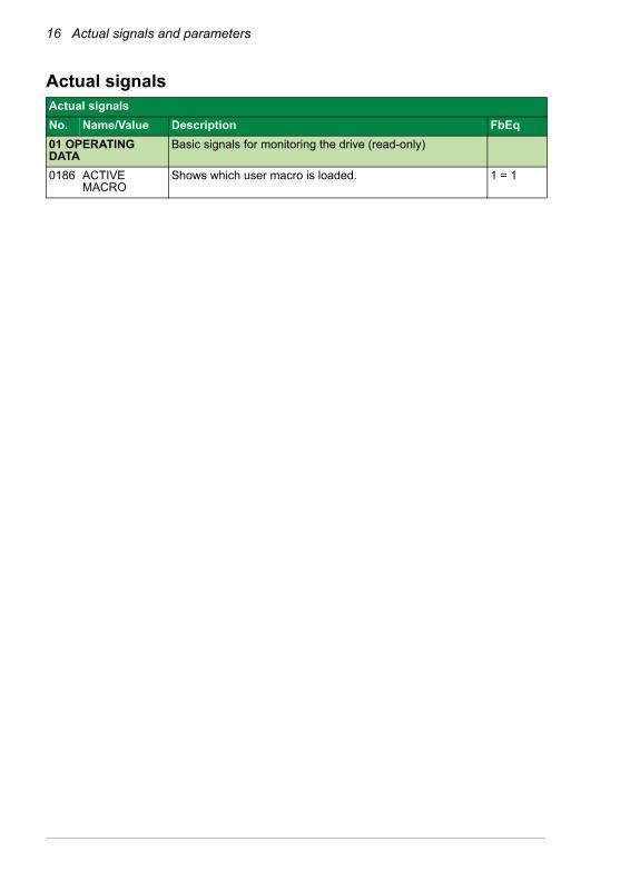
Actual signals Actual signals
No. Name/Value Description FbEq
01 OPERATING DATA
Basic signals for monitoring the drive (read-only)
0186 ACTIVE MACRO
Shows which user macro is loaded. 1 = 1
Actual signals and parameters 17
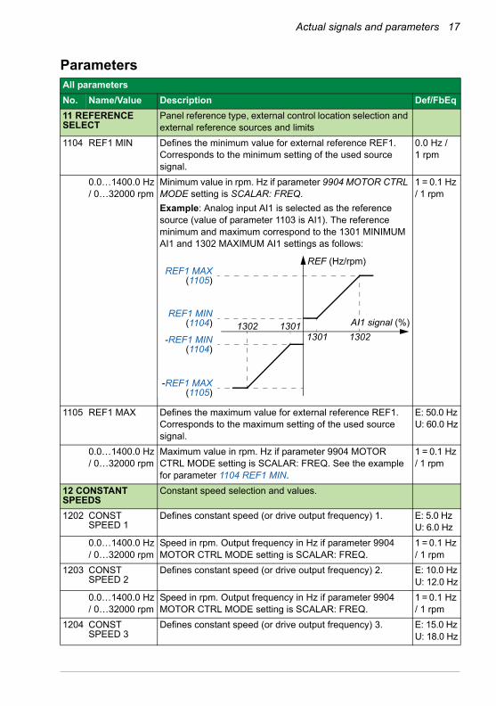
ParametersAll parameters
No. Name/Value Description Def/FbEq
11 REFERENCE SELECT
Panel reference type, external control location selection and external reference sources and limits
1104 REF1 MIN Defines the minimum value for external reference REF1. Corresponds to the minimum setting of the used source signal.
0.0 Hz / 1 rpm
0.0…1400.0 Hz / 0…32000 rpm
Minimum value in rpm. Hz if parameter 9904 MOTOR CTRL MODE setting is SCALAR: FREQ.
Example: Analog input AI1 is selected as the reference source (value of parameter 1103 is AI1). The reference minimum and maximum correspond to the 1301 MINIMUM AI1 and 1302 MAXIMUM AI1 settings as follows:
1 = 0.1 Hz / 1 rpm
1105 REF1 MAX Defines the maximum value for external reference REF1. Corresponds to the maximum setting of the used source signal.
E: 50.0 HzU: 60.0 Hz
0.0…1400.0 Hz / 0…32000 rpm
Maximum value in rpm. Hz if parameter 9904 MOTOR CTRL MODE setting is SCALAR: FREQ. See the example for parameter 1104 REF1 MIN.
1 = 0.1 Hz / 1 rpm
12 CONSTANT SPEEDS
Constant speed selection and values.
1202 CONST SPEED 1
Defines constant speed (or drive output frequency) 1. E: 5.0 HzU: 6.0 Hz
0.0…1400.0 Hz / 0…32000 rpm
Speed in rpm. Output frequency in Hz if parameter 9904 MOTOR CTRL MODE setting is SCALAR: FREQ.
1 = 0.1 Hz / 1 rpm
1203 CONST SPEED 2
Defines constant speed (or drive output frequency) 2. E: 10.0 HzU: 12.0 Hz
0.0…1400.0 Hz / 0…32000 rpm
Speed in rpm. Output frequency in Hz if parameter 9904 MOTOR CTRL MODE setting is SCALAR: FREQ.
1 = 0.1 Hz / 1 rpm
1204 CONST SPEED 3
Defines constant speed (or drive output frequency) 3. E: 15.0 HzU: 18.0 Hz
REF (Hz/rpm)REF1 MAX
(1105)
REF1 MIN(1104)
-REF1 MIN(1104)
-REF1 MAX(1105)
AI1 signal (%)1302 13011301 1302
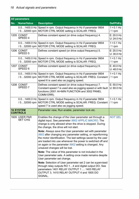
18 Actual signals and parameters
0.0…1400.0 Hz / 0…32000 rpm
Speed in rpm. Output frequency in Hz if parameter 9904 MOTOR CTRL MODE setting is SCALAR: FREQ.
1 = 0.1 Hz / 1 rpm
1205 CONST SPEED 4
Defines constant speed (or drive output frequency) 4. E: 20.0 HzU: 24.0 Hz
0.0…1400.0 Hz / 0…32000 rpm
Speed in rpm. Output frequency in Hz if parameter 9904 MOTOR CTRL MODE setting is SCALAR: FREQ.
1 = 0.1 Hz / 1 rpm
1206 CONST SPEED 5
Defines constant speed (or drive output frequency) 5. E: 25.0 HzU: 30.0 Hz
0.0…1400.0 Hz / 0…32000 rpm
Speed in rpm. Output frequency in Hz if parameter 9904 MOTOR CTRL MODE setting is SCALAR: FREQ.
1 = 0.1 Hz / 1 rpm
1207 CONST SPEED 6
Defines constant speed (or drive output frequency) 6. E: 40.0 HzU: 48.0 Hz
0.0…1400.0 Hz / 0…32000 rpm
Speed in rpm. Output frequency in Hz if parameter 9904 MOTOR CTRL MODE setting is SCALAR: FREQ. Constant speed 6 is used also as jogging speed.
1 = 0.1 Hz / 1 rpm
1208 CONST SPEED 7
Defines constant speed (or drive output frequency) 7. Constant speed 7 is used also as jogging speed or with fault functions (3001 AI<MIN FUNCTION and 3002 PANEL COMM ERR).
E: 50.0 HzU: 60.0 Hz
0.0…1400.0 Hz / 0…32000 rpm
Speed in rpm. Output frequency in Hz if parameter 9904 MOTOR CTRL MODE setting is SCALAR: FREQ. Constant speed 7 is used also as jogging speed.
1 = 0.1 Hz / 1 rpm
16 SYSTEM CONTROLS
Parameter view, Run enable, parameter lock etc.
1605 USER PAR SET CHG
Enables the change of the User parameter set through a digital input. See parameter 9902 APPLIC MACRO. The change is only allowed when the drive is stopped. During the change, the drive will not start.
Note: Always save the User parameter set with parameter 9902 after changing any parameter setting, or reperforming the motor identification. The last settings saved by the user are loaded into use whenever the power is switched off and on again or the parameter 9902 setting is changed. Any unsaved changes will be lost.
Note: The value of this parameter is not included in the User parameter sets. A setting once made remains despite User parameter set change.
Note: Selection of User parameter set 2 can be supervised through relay outputs RO 1…4 and digital output DO. See parameters 1401 RELAY OUTPUT 1 … 1403 RELAY OUTPUT 3, 1410 RELAY OUTPUT 4 and 1805 DO SIGNAL.
NOT SEL
All parameters
No. Name/Value Description Def/FbEq
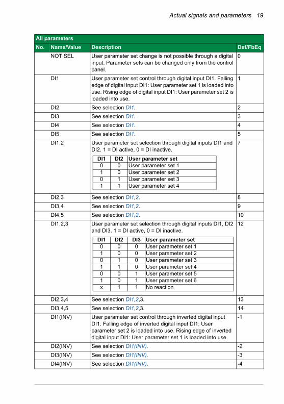
Actual signals and parameters 19
NOT SEL User parameter set change is not possible through a digital input. Parameter sets can be changed only from the control panel.
0
DI1 User parameter set control through digital input DI1. Falling edge of digital input DI1: User parameter set 1 is loaded into use. Rising edge of digital input DI1: User parameter set 2 is loaded into use.
1
DI2 See selection DI1. 2
DI3 See selection DI1. 3
DI4 See selection DI1. 4
DI5 See selection DI1. 5
DI1,2 User parameter set selection through digital inputs DI1 and DI2. 1 = DI active, 0 = DI inactive.
7
DI2,3 See selection DI1,2. 8
DI3,4 See selection DI1,2. 9
DI4,5 See selection DI1,2. 10
DI1,2,3 User parameter set selection through digital inputs DI1, DI2 and DI3. 1 = DI active, 0 = DI inactive.
12
DI2,3,4 See selection DI1,2,3. 13
DI3,4,5 See selection DI1,2,3. 14
DI1(INV) User parameter set control through inverted digital input DI1. Falling edge of inverted digital input DI1: User parameter set 2 is loaded into use. Rising edge of inverted digital input DI1: User parameter set 1 is loaded into use.
-1
DI2(INV) See selection DI1(INV). -2
DI3(INV) See selection DI1(INV). -3
DI4(INV) See selection DI1(INV). -4
All parameters
No. Name/Value Description Def/FbEq
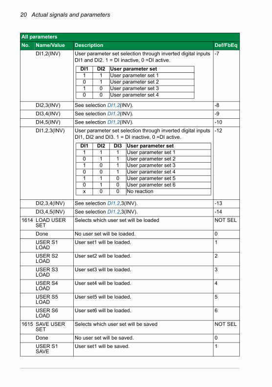
DI1 DI2 User parameter set0 0 User parameter set 11 0 User parameter set 20 1 User parameter set 31 1 User parameter set 4
DI1 DI2 DI3 User parameter set0 0 0 User parameter set 11 0 0 User parameter set 20 1 0 User parameter set 31 1 0 User parameter set 40 0 1 User parameter set 51 0 1 User parameter set 6x 1 1 No reaction
20 Actual signals and parameters
DI1,2(INV) User parameter set selection through inverted digital inputs DI1 and DI2. 1 = DI inactive, 0 =DI active.
-7
DI2,3(INV) See selection DI1,2(INV). -8
DI3,4(INV) See selection DI1,2(INV). -9
DI4,5(INV) See selection DI1,2(INV). -10
DI1,2,3(INV) User parameter set selection through inverted digital inputs DI1, DI2 and DI3. 1 = DI inactive, 0 =DI active.
-12
DI2,3,4(INV) See selection DI1,2,3(INV). -13
DI3,4,5(INV) See selection DI1,2,3(INV). -14
1614 LOAD USER SET
Selects which user set will be loaded NOT SEL
Done No user set will be loaded. 0
USER S1 LOAD
User set1 will be loaded. 1
USER S2 LOAD
User set2 will be loaded. 2
USER S3 LOAD
User set3 will be loaded. 3
USER S4 LOAD
User set4 will be loaded. 4
USER S5 LOAD
User set5 will be loaded. 5
USER S6 LOAD
User set6 will be loaded. 6
1615 SAVE USER SET
Selects which user set will be saved NOT SEL
Done No user set will be saved. 0
USER S1 SAVE
User set1 will be saved. 1
All parameters
No. Name/Value Description Def/FbEq
DI1 DI2 User parameter set1 1 User parameter set 10 1 User parameter set 21 0 User parameter set 30 0 User parameter set 4
DI1 DI2 DI3 User parameter set1 1 1 User parameter set 10 1 1 User parameter set 21 0 1 User parameter set 30 0 1 User parameter set 41 1 0 User parameter set 50 1 0 User parameter set 6x 0 0 No reaction
Actual signals and parameters 21
USER S2 SAVE
User set2 will be saved. 2
USER S3 SAVE
User set3 will be saved. 3
USER S4 SAVE
User set4 will be saved. 4
USER S5 SAVE
User set5 will be saved. 5
USER S6 SAVE
User set6 will be saved. 6
20 LIMITS Drive operation limits.
Speed values are used in vector control and frequency values are used in scalar control. The control mode is selected by parameter 9904 MOTOR CTRL MODE.
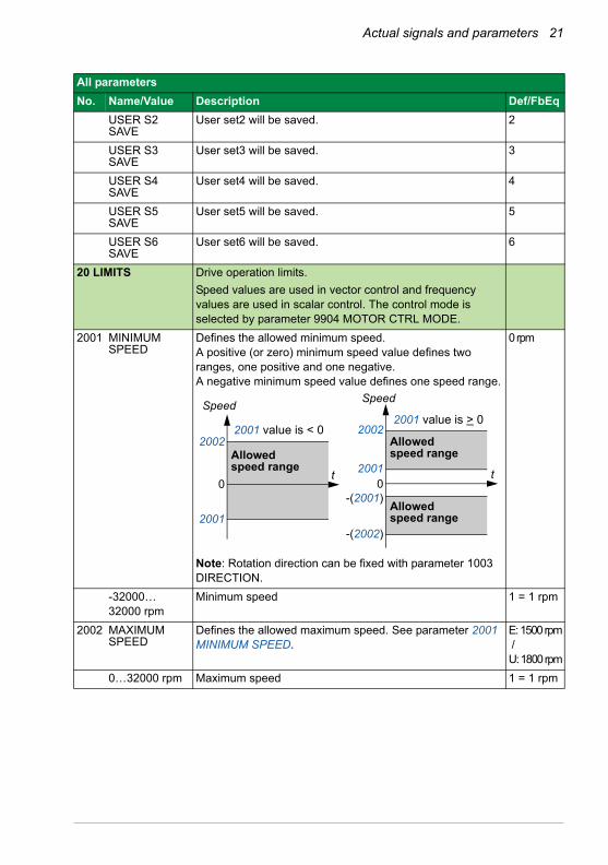
2001 MINIMUM SPEED
Defines the allowed minimum speed. A positive (or zero) minimum speed value defines two ranges, one positive and one negative.A negative minimum speed value defines one speed range.
Note: Rotation direction can be fixed with parameter 1003 DIRECTION.
0rpm
-32000…32000 rpm
Minimum speed 1 = 1 rpm
2002 MAXIMUM SPEED
Defines the allowed maximum speed. See parameter 2001 MINIMUM SPEED.
E: 1500rpm /U: 1800rpm
0…32000 rpm Maximum speed 1 = 1 rpm
All parameters
No. Name/Value Description Def/FbEq
2002
2001
0
Speed
2001 value is < 0 2001 value is > 0
2002
2001 0
-(2001)
-(2002)
t t
Allowedspeed range
Allowedspeed range
Allowedspeed range
Speed
22 Actual signals and parameters
2007 MINIMUM FREQ
Defines the minimum limit for the drive output frequency.A positive (or zero) minimum frequency value defines two ranges, one positive and one negative.A negative minimum frequency value defines one speed range.
Note: MINIMUM FREQ < MAXIMUM FREQ.
0.0 Hz
-1400.0 …1400.0 Hz
Minimum frequency 1 = 0.1 Hz
2008 MAXIMUM FREQ
Defines the maximum limit for the drive output frequency. E: 50.0 HzU: 60.0 Hz
0.0…1400.0 Hz Maximum frequency 1 = 0.1 Hz
22 ACCEL/DECEL Acceleration and deceleration times
2201 ACC/DEC 1/2 SEL
Defines the source from which the drive reads the signal that selects between the two ramp pairs, acceleration/deceleration pair 1 and 2.Ramp pair 1 is defined by parameters 2202…2204.Ramp pair 2 is defined by parameters 2205…2207.
DI5
NOT SEL Ramp pair 1 is used. 0
DI1 Digital input DI1. 1 = ramp pair 2, 0 = ramp pair 1. 1
DI2 See selection DI1. 2
DI3 See selection DI1. 3
DI4 See selection DI1. 4
DI5 See selection DI1. 5
COMM Fieldbus interface as the source for ramp pair 1/2 selection, ie Control word 0301 FB CMD WORD 1 bit 10. The Control word is sent by the fieldbus controller through the fieldbus adapter or embedded fieldbus (Modbus) to the drive. For the Control word bits.
Note: This setting applies only for the DCU profile.
7
SEQ PROG Sequence programming ramp defined by parameter 8422 ST1 RAMP (or 8423/…/8492)
10
All parameters
No. Name/Value Description Def/FbEq
2008
2007
0
f 2008 value is < 0
2007 value is > 0 f
2008
2007 0
-(2007)
-(2008)
t t
Allowedfrequency range
Allowedfrequency range
Allowedfrequency range
Actual signals and parameters 23
SMOOTH START
Smooth start ramp time will be effect in ramp time according to settings of parameter 2621...2624.
11
DI1(INV) Inverted digital input DI1. 0 = ramp pair 2, 1 = ramp pair 1. -1
DI2(INV) See selection DI1(INV). -2
DI3(INV) See selection DI1(INV). -3
DI4(INV) See selection DI1(INV). -4
DI5(INV) See selection DI1(INV). -5
25 CRITICAL SPEEDS
Speed bands within which the drive is not allowed to operate.
2502 CRIT SPEED 1 LO
Defines the minimum limit for critical speed/frequency range 1.
0.0 Hz / 1 rpm
0.0…1400.0 Hz / 0…32000 rpm
Limit in rpm. Limit in Hz if parameter 9904 MOTOR CTRL MODE setting is SCALAR: FREQ. The value cannot be above the maximum (parameter 2503 CRIT SPEED 1 HI).
1 = 0.1 Hz / 1 rpm
2503 CRIT SPEED 1 HI
Defines the maximum limit for critical speed/frequency range 1.
0.0 Hz / 1 rpm
0.0…1400.0 Hz / 0…32000 rpm
Limit in rpm. Limit in Hz if parameter 9904 MOTOR CTRL MODE setting is SCALAR: FREQ. The value cannot be below the minimum (parameter 2502 CRIT SPEED 1 LO).
1 = 0.1 Hz / 1 rpm
2504 CRIT SPEED 2 LO
See parameter 2502 CRIT SPEED 1 LO. 0.0 Hz / 1 rpm
0.0…1400.0 Hz / 0…32000 rpm
See parameter 2502. 1 = 0.1 Hz / 1 rpm
2505 CRIT SPEED 2 HI
See parameter 2503 CRIT SPEED 1 HI. 0.0 Hz / 1 rpm
0.0…1400.0 Hz / 0…32000 rpm
See parameter 2503. 1 = 0.1 Hz / 1 rpm
2506 CRIT SPEED 3 LO
See parameter 2502 CRIT SPEED 1 LO. 0.0 Hz / 1 rpm
0.0…1400.0 Hz / 0…32000 rpm
See parameter 2502. 1 = 0.1 Hz / 1 rpm
2507 CRIT SPEED 3 HI
See parameter 2503 CRIT SPEED 1 HI. 0.0 Hz / 1 rpm
0.0…1400.0 Hz / 0…32000 rpm
See parameter 2503. 1 = 0.1 Hz / 1 rpm
26 MOTOR CONTROL
Motor control variables
2611 USER DEFINED F1
Defines the first frequency point of the custom U/f curve. 10.0 Hz
0.0…1400.0 Hz Frequency 1 = 0.1 Hz
2613 USER DEFINED F2
Defines the second frequency point of the custom U/f curve. 20.0 Hz
All parameters
No. Name/Value Description Def/FbEq
24 Actual signals and parameters
0.0…1400.0 Hz Frequency 1 = 0.1 Hz
2615 USER DEFINED F3
Defines the third frequency point of the custom U/f curve. 25.0 Hz
0.0…1400.0 Hz Frequency 1 = 0.1 Hz
2617 USER DEFINED F4
Defines the fourth frequency point of the custom U/f curve. 40.0 Hz
0.0…1400.0 Hz Frequency 1 = 0.1 Hz
30 FAULT FUNCTIONS
Programmable protection functions
3029 FAULT RAMP STOP
Selects how the drive reacts when the drive trips to fault excepting Hardware critical faults (OVERCURRENT, DC OVERVOLT and SHORT CIRC), SAFE TORQUE OFF, STO1 LOST and STO2 LOST faults.
1
DISABLE Drive makes coast stop when drive trips fault. 0
ENABLE Drive makes emergency ramp stop when drive trips fault using the emergency ramp stop deceleration time (par. 22.08).
1
40 PROCESS PID SET 1
Process PID (PID1) control parameter set 1.
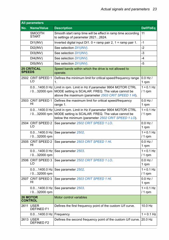
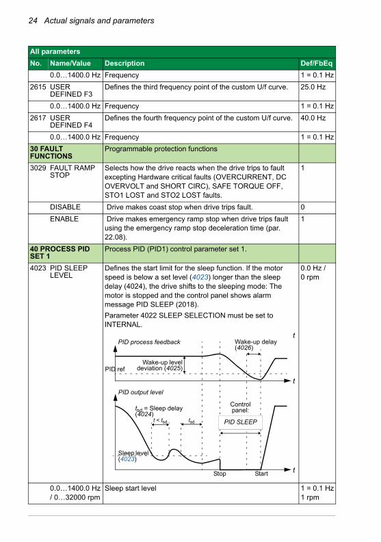
4023 PID SLEEP LEVEL
Defines the start limit for the sleep function. If the motor speed is below a set level (4023) longer than the sleep delay (4024), the drive shifts to the sleeping mode: The motor is stopped and the control panel shows alarm message PID SLEEP (2018).
Parameter 4022 SLEEP SELECTION must be set to INTERNAL.
0.0 Hz /0 rpm
0.0…1400.0 Hz / 0…32000 rpm
Sleep start level 1 = 0.1 Hz1 rpm
All parameters
No. Name/Value Description Def/FbEq
Wake-up leveldeviation (4025)
t < tsd
PID output level
PID process feedback
Stop
tsd = Sleep delay (4024)
Sleep level (4023)
Start
Wake-up delay (4026)
tsd
t
Control panel:
PID SLEEP
t
t
PID ref
Actual signals and parameters 25
99 START-UP DATA Language selection. Definition of motor set-up data.
9902 APPLIC MACRO
Selects the application macro. ABB STANDARD
ABB STANDARD
Standard macro for constant speed applications 1
3-WIRE 3-wire macro for constant speed applications 2
ALTERNATE Alternate macro for start forward and start reverse applications
3
MOTOR POT Motor potentiometer macro for digital signal speed control applications
4
HAND/AUTO Hand/Auto macro to be used when two control devices are connected to the drive:
• Device 1 communicates through the interface defined by external control location EXT1.
• Device 2 communicates through the interface defined by external control location EXT2.
EXT1 or EXT2 is active at a time. Switching between EXT1/2 through digital input.
5
PID CONTROL PID control. For applications in which the drive controls a process value, eg pressure control by the drive running the pressure boost pump. Measured pressure and the pressure reference are connected to the drive.
6
TORQUE CTRL
Torque control macro 8
AC500 MODBUS
AC500 PLC macro. 10
LOAD FD SET FlashDrop parameter values as defined by the FlashDrop file. Parameter view is selected by parameter 1611 PARAMETER VIEW.
FlashDrop is an optional device for fast copying of parameters to unpowered drives. FlashDrop allows easy customization of the parameter list, eg selected parameters can be hidden. For more information, see MFDT-01 FlashDrop user’s manual (3AFE68591074 [English]).
31
USER S1 LOAD
User 1 macro loaded into use. Before loading, check that the saved parameter settings and the motor model are suitable for the application.
0
USER S1 SAVE
Save User 1 macro. Stores the current parameter settings and the motor model.
-1
USER S2 LOAD
User 2 macro loaded into use. Before loading, check that the saved parameter settings and the motor model are suitable for the application.
-2
All parameters
No. Name/Value Description Def/FbEq
26 Actual signals and parameters
USER S2 SAVE
Save User 2 macro. Stores the current parameter settings and the motor model.
-3
USER S3 LOAD
User 3 macro loaded into use. Before loading, check that the saved parameter settings and the motor model are suitable for the application.
-4
USER S3 SAVE
Save User 3 macro. Stores the current parameter settings and the motor model.
-5
USER S4 LOAD
User 4 macro loaded into use. Before loading, check that the saved parameter settings and the motor model are suitable for the application.
-6
USER S4 SAVE
Save User 4 macro. Stores the current parameter settings and the motor model.
-7
USER S5 LOAD
User 5 macro loaded into use. Before loading, check that the saved parameter settings and the motor model are suitable for the application.
-8
USER S5 SAVE
Save User 5 macro. Stores the current parameter settings and the motor model.
-9
USER S6 LOAD
User 6 macro loaded into use. Before loading, check that the saved parameter settings and the motor model are suitable for the application.
-10
USER S6 SAVE
Save User 6 macro. Stores the current parameter settings and the motor model.
-11
9907 MOTOR NOM FREQ
Defines the nominal motor frequency, ie the frequency at which the output voltage equals the motor nominal voltage:
Field weakening point = Nom. frequency · Supply voltage / Motor nom. voltage
E: 50.0 HzU: 60.0 Hz
0.0…1400.0 Hz Frequency 1 = 0.1 Hz
9908 MOTOR NOM SPEED
Defines the nominal motor speed. Must be equal to the value on the motor rating plate.
Type dependent
50…32000 rpm Speed 1 = 1 rpm
All parameters
No. Name/Value Description Def/FbEq
Further information
Product and service inquiries
Address any inquiries about the product to your local ABB representative, quoting the type designation and serial number of the unit in question. A listing of ABB sales, support and service contacts can be found by navigating to www.abb.com/searchchannels.
Product training
For information on ABB product training, navigate to www.abb.com/drives and select Training courses.
Providing feedback on ABB Drives manuals
Your comments on our manuals are welcome. Go to www.abb.com/drives and select Document Library – Manuals feedback form (LV AC drives).
Document library on the Internet
You can find manuals and other product documents in PDF format on the Internet. Go to www.abb.com/drives and select Document Library. You can browse the library or enter selection criteria, for example a document code, in the search field.

www.abb.com/drives www.abb.com/drivespartners
3AXD50000017574 Rev A (EN) 2014-07-09
Contact us