Embed Size (px)
Citation preview

Engineering Materials 2An Introduction to Microstructures, Processing and Design

This Page is Intentionally Left Blank

Engineering Materials 2An Introduction to Microstructures,Processing and Design
Third Edition
Michael F. Ashby
and
David R. H. JonesDepartment of Engineering, Cambridge University, UK
AMSTERDAM • BOSTON • HEIDELBERG • LONDON • NEW YORK • OXFORD
PARIS • SAN DIEGO • SAN FRANCISCO • SINGAPORE • SYDNEY • TOKYO
Butterworth-Heinemann is an imprint of Elsevier

Butterworth-Heinemann is an imprint of ElsevierLinacre House, Jordan Hill, Oxford OX2 8DP30 Corporate Drive, Suite 400, Burlington, MA 01803
First edition 1986Reprinted with corrections 1988Reprinted 1989, 1992Second edition 1998Reprinted 1999, 2000, 2001Third edition 2006
Copyright © 2006, Michael F. Ashby and David R. H. Jones.All rights reserved
The rights of Michael F. Ashby and David R. H. Jones to be identified asthe authors of this work has been asserted in accordance with the Copyright,Designs and Patents Act 1988
No part of this publication may be reproduced in any material form (includingphotocopying or storing in any medium by electronic means and whetheror not transiently or incidentally to some other use of this publication) withoutthe written permission of the copyright holder except in accordance with theprovisions of the Copyright, Designs and Patents Act 1988 or under the terms ofa licence issued by the Copyright Licensing Agency Ltd, 90 Tottenham Court Road,London, England W1T 4LP. Applications for the copyright holder’s writtenpermission to reproduce any part of this publication should be addressedto the publisher
Permissions may be sought directly from Elsevier’s Science and Technology RightsDepartment in Oxford, UK; phone: (+44) (0) 1865 843830; fax: (+44) (0) 1865 853333;e-mail: [email protected]. You may also complete your request on-line viathe Elsevier Science homepage (http://www.elsevier.com), by selecting ‘Customer Support’and then ‘Obtaining Permissions’
British Library Cataloguing in Publication DataA catalogue record for this book is available from the British Library
Library of Congress Cataloguing in Publication DataA catalogue record for this book is available from the British Library
ISBN–13: 978-0-7506-6381-6ISBN–10: 0-7506-6381-2
For information on all Butterworth-Heinemann publicationsplease visit our web site at http://www.books.elsevier.com
Printed and bound in UK06 07 08 09 10 10 9 8 7 6 5 4 3 2 1
Working together to grow libraries in developing countries
www.elsevier.com | www.bookaid.org | www.sabre.org
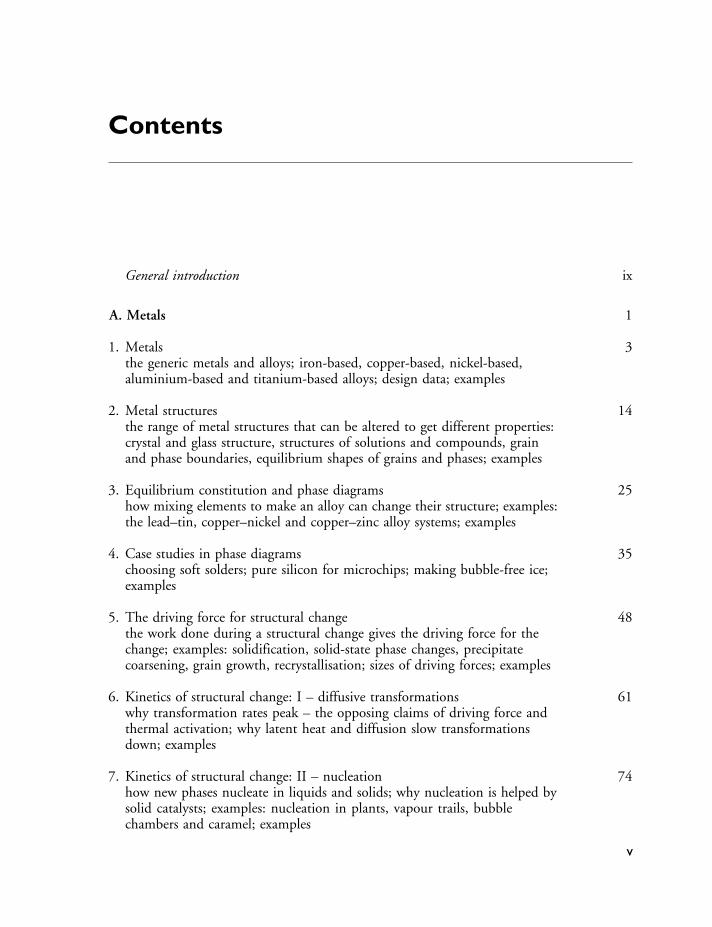
Contents
General introduction ix
A. Metals 1
1. Metalsthe generic metals and alloys; iron-based, copper-based, nickel-based,aluminium-based and titanium-based alloys; design data; examples
3
2. Metal structuresthe range of metal structures that can be altered to get different properties:crystal and glass structure, structures of solutions and compounds, grainand phase boundaries, equilibrium shapes of grains and phases; examples
14
3. Equilibrium constitution and phase diagramshow mixing elements to make an alloy can change their structure; examples:the lead–tin, copper–nickel and copper–zinc alloy systems; examples
25
4. Case studies in phase diagramschoosing soft solders; pure silicon for microchips; making bubble-free ice;examples
35
5. The driving force for structural changethe work done during a structural change gives the driving force for thechange; examples: solidification, solid-state phase changes, precipitatecoarsening, grain growth, recrystallisation; sizes of driving forces; examples
48
6. Kinetics of structural change: I – diffusive transformationswhy transformation rates peak – the opposing claims of driving force andthermal activation; why latent heat and diffusion slow transformationsdown; examples
61
7. Kinetics of structural change: II – nucleationhow new phases nucleate in liquids and solids; why nucleation is helped bysolid catalysts; examples: nucleation in plants, vapour trails, bubblechambers and caramel; examples
74
v
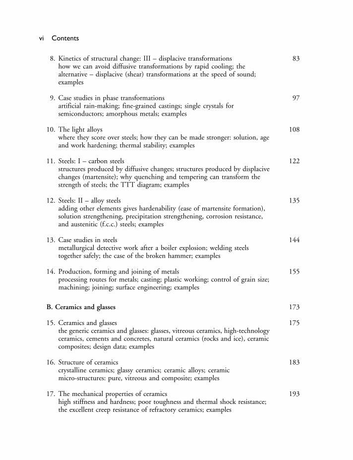
vi Contents
8. Kinetics of structural change: III – displacive transformationshow we can avoid diffusive transformations by rapid cooling; thealternative – displacive (shear) transformations at the speed of sound;examples
83
9. Case studies in phase transformationsartificial rain-making; fine-grained castings; single crystals forsemiconductors; amorphous metals; examples
97
10. The light alloyswhere they score over steels; how they can be made stronger: solution, ageand work hardening; thermal stability; examples
108
11. Steels: I – carbon steelsstructures produced by diffusive changes; structures produced by displacivechanges (martensite); why quenching and tempering can transform thestrength of steels; the TTT diagram; examples
122
12. Steels: II – alloy steelsadding other elements gives hardenability (ease of martensite formation),solution strengthening, precipitation strengthening, corrosion resistance,and austenitic (f.c.c.) steels; examples
135
13. Case studies in steelsmetallurgical detective work after a boiler explosion; welding steelstogether safely; the case of the broken hammer; examples
144
14. Production, forming and joining of metalsprocessing routes for metals; casting; plastic working; control of grain size;machining; joining; surface engineering; examples
155
B. Ceramics and glasses 173
15. Ceramics and glassesthe generic ceramics and glasses: glasses, vitreous ceramics, high-technologyceramics, cements and concretes, natural ceramics (rocks and ice), ceramiccomposites; design data; examples
175
16. Structure of ceramicscrystalline ceramics; glassy ceramics; ceramic alloys; ceramicmicro-structures: pure, vitreous and composite; examples
183
17. The mechanical properties of ceramicshigh stiffness and hardness; poor toughness and thermal shock resistance;the excellent creep resistance of refractory ceramics; examples
193

Contents vii
18. The statistics of brittle fracture and case studyhow the distribution of flaw sizes gives a dispersion of strength: theWeibull distribution; why the strength falls with time (static fatigue);case study: the design of pressure windows; examples
202
19. Production, forming and joining of ceramicsprocessing routes for ceramics; making and pressing powders to shape;working glasses; making high-technology ceramics; joining ceramics;applications of high-performance ceramics; examples
213
20. Special topic: cements and concreteshistorical background; cement chemistry; setting and hardening ofcement; strength of cement and concrete; high-strength cements; examples
227
C. Polymers and composites 239
21. Polymersthe generic polymers: thermoplastics, thermosets, elastomers, naturalpolymers; design data; examples
241
22. The structure of polymersgiant molecules and their architecture; molecular packing: amorphous orcrystalline?; examples
251
23. Mechanical behaviour of polymershow the modulus and strength depend on temperature and time; examples
262
24. Production, forming and joining of polymersmaking giant molecules by polymerisation; polymer “alloys”; forming andjoining polymers; examples
279
25. Composites: fibrous, particulate and foamedhow adding fibres or particles to polymers can improve their stiffness,strength and toughness; why foams are good for absorbing energy;examples
289
26. Special topic: woodone of nature’s most successful composite materials; examples
306
D. Designing with metals, ceramics, polymers and composites 317
27. Design with materialsthe design-limiting properties of metals, ceramics, polymers andcomposites; design methodology; examples
319
viii Contents
28. Case studies in design 3261. Designing with metals: conveyor drums for an iron ore terminal2. Designing with ceramics: ice forces on offshore structures3. Designing with polymers: a plastic wheel4. Designing with composites: materials for violin bodies
29. Engineering failures and disasters – the ultimate test of design 352IntroductionCase study 1: the Tay Bridge railway disaster – 28 December 1879Case study 2: the Comet air disasters – 10 January and 8 April 1954Case study 3: the Eschede railway disaster – 5 June 1998Case study 4: a fatal bungee-jumping accident
Appendix 1 Teaching yourself phase diagrams 380Appendix 2 Symbols and formulae 434References 442
Index 445

General introduction
Materials are evolving today faster than at any time in history. Industrial nationsregard the development of new and improved materials as an “underpinningtechnology” – one which can stimulate innovation in all branches of engineer-ing, making possible new designs for structures, appliances, engines, electricaland electronic devices, processing and energy conservation equipment, andmuch more. Many of these nations have promoted government-backed initia-tives to promote the development and exploitation of new materials: their listsgenerally include “high-performance” composites, new engineering ceramics,high-strength polymers, glassy metals, and new high-temperature alloys for gasturbines. These initiatives are now being felt throughout engineering, and havealready stimulated design of a new and innovative range of consumer products.
So the engineer must be more aware of materials and their potential thanever before. Innovation, often, takes the form of replacing a component madeof one material (a metal, say) with one made of another (a polymer, perhaps),and then redesigning the product to exploit, to the maximum, the potentialoffered by the change. The engineer must compare and weigh the propertiesof competing materials with precision: the balance, often, is a delicate one. Itinvolves an understanding of the basic properties of materials; of how theseare controlled by processing; of how materials are formed, joined and finished;and of the chain of reasoning that leads to a successful choice.
This book aims to provide this understanding. It complements our otherbook on the properties and applications of engineering materials,∗ but it is notnecessary to have read that to understand this. In it, we group materials intofour classes: Metals, Ceramics, Polymers and Composites, and we examine eachin turn. In any one class there are common underlying structural features (thelong-chain molecules in polymers, the intrinsic brittleness of ceramics, or themixed materials of composites) which, ultimately, determine the strengths andweaknesses (the “design-limiting” properties) of each in the engineering context.
And so, as you can see from the Contents list, the chapters are arranged ingroups, with a group of chapters to describe each of the four classes of materials.In each group we first introduce the major families of materials that go to makeup each materials class. We then outline the main microstructural features ofthe class, and show how to process or treat them to get the structures (really, inthe end, the properties) that we want. Each group of chapters is illustrated by
∗ M. F. Ashby and D. R. H. Jones, Engineering Materials 1: An Introduction to their Properties and Applications,2nd edition, Butterworth-Heinemann, 1996.
ix

x General introduction
Case Studies designed to help you understand the basic material. And finally welook at the role of materials in the design of engineering devices, mechanismsor structures, and develop a methodology for materials selection. One subject –Phase Diagrams – can be heavy going. We have tried to overcome this by givinga short programmed-learning course on phase diagrams. If you work throughthis when you come to the chapter on phase diagrams you will know all youneed to about the subject. It will take you about 4 hours.
At the end of each chapter you will find a set of problems: try to do themwhile the topic is still fresh in your mind – in this way you will be able toconsolidate, and develop, your ideas as you go along.
To the lecturer
This book has been written as a second-level course for engineering students. Itprovides a concise introduction to the microstructures and processing of materials(metals, ceramics, polymers and composites) and shows how these are related tothe properties required in engineering design. It is designed to follow on fromour first-level text on the properties and applications of engineering materials,∗but it is completely self-contained and can be used by itself.
Each chapter is designed to provide the content of a 50-minute lecture. Eachblock of four or so chapters is backed up by a set of Case Studies, which illustrateand consolidate the material they contain. There are special sections on design,and on such materials as wood, cement and concrete. And there are problemsfor the student at the end of each chapter for which worked solutions can beobtained separately, from the publisher. In order to ease the teaching of phasediagrams (often a difficult topic for engineering students) we have included aprogrammed-learning text which has proved helpful for our own students.
We have tried to present the material in an uncomplicated way, and to makethe examples entertaining, while establishing basic physical concepts and theirapplication to materials processing. We found that the best way to do thiswas to identify a small set of “generic” materials of each class (of metals, ofceramics, etc.) which broadly typified the class, and to base the development onthese; they provide the pegs on which the discussion and examples are hung.But the lecturer who wishes to draw other materials into the discussion shouldnot find this difficult.
Acknowledgements
We wish to thank Prof. G. A. Chadwick for permission to reprint Fig. A1.34(p. 417) and K. J. Pascoe and Van Nostrand Reinhold Co. for permission toreprint Fig. A1.41 (p. 422).
∗ M. F. Ashby and D. R. H. Jones, Engineering Materials 1: An Introduction to their Properties and Applications,3rd edition, Butterworth-Heinemann, 2005.

Acknowledgements xi
Figures 29.1 and 29.4 are reprinted courtesy of University of St Andrews.Figure 29.6 is reprinted courtesy of the Dundee Central Library.Figure 29.2 is reprinted from Engineering Failure Analysis, Jones, D. R. H.,
The Tay Bridge disaster, with permission from Elsevier.Figures 29.11 and 29.14 are reprinted from Engineering Failure Analysis 12,
Richard et al., Fracture in a rubber-sprung railway wheel, 986–999, © 2005,with permission from Elsevier.
Figure 29.13 is reprinted from Engineering Failure Analysis 11, Esslinger et al.,The railway accident at Eschede, 515–535, © 2004, with permission fromElsevier.
Figures 29.15–29.19 are reprinted from Engineering Failure Analysis 11, Jones,D. R. H., Analysis of a fatal bungee-jumping accident, 857–872, © 2004,with permission from Elsevier.
Accompanying Resources
The following accompanying web-based resources are available to teachers andlecturers who adopt or recommend this text for class use. For further detailsand access to these resources please go to http://textbooks.elsevier.com
Instructor’s Manual
A full Solutions Manual with worked answers to the exercises in the main textis available for downloading.
Image bank
An image bank of downloadable PDF versions of the figures from the book isavailable for use in lecture slides and class presentations.
Online Materials Science Tutorials
A series of online materials science tutorials accompanies Engineering Materials1 and 2. These were developed by Alan Crosky, Mark Hoffman, Paul Munroeand Belinda Allen at the University of New South Wales (UNSW) Australia,based upon earlier editions of the books. The group is particularly interestedin the effective and innovative use of technology in teaching. They realisedthe potential of the material for the teaching of Materials Engineering to theirstudents in an online environment and have developed and then used thesevery popular tutorials for a number of years at UNSW. The results of thiswork have also been published and presented extensively.
The tutorials are designed for students of materials science as well as forthose studying materials as a related or elective subject, for example mechanicalor civil engineering students. They are ideal for use as ancillaries to formalteaching programs, and may also be used as the basis for quick refresher coursesfor more advanced materials science students. By picking selectively from therange of tutorials available they will also make ideal subject primers for studentsfrom related faculties.
The software has been developed as a self-paced learning tool, separatedinto learning modules based around key materials science concepts. For furtherinformation on accessing the tutorials, and the conditions for their use, pleasego to http://textbooks.elsevier.com
xii

Accompanying Resources xiii
About the authors of the Tutorials
Alan Crosky is an Associate Professor in the School of Materials Science andEngineering, UNSW. His teaching specialties include metallurgy, compositesand fractography.
Belinda Allen is an Educational Graphics Manager and Educational Designerat the Educational Development and Technology Centre, UNSW. She providesconsultation and production support for the academic community and designsand presents workshops and online resources on image production and webdesign.
Mark Hoffman is an Associate Professor in the School of Materials Scienceand Engineering, UNSW. His teaching specialties include fracture, numericalmodelling, mechanical behaviour of materials and engineering management.
Paul Munroe has a joint appointment as Professor in the School of Mate-rials Science and Engineering and Director of the Electron Microscope Unit,UNSW. His teaching specialties are the deformation and strengthening mech-anisms of materials and crystallographic and microstructural characterisation.

This Page is Intentionally Left Blank

A. Metals

This Page is Intentionally Left Blank

Chapter 1Metals
Introduction
This first group of chapters looks at metals. There are so many differentmetals – literally hundreds of them – that it is impossible to remember themall. It isn’t necessary – nearly all have evolved from a few “generic” metals andare simply tuned-up modifications of the basic recipes. If you know about thegeneric metals, you know most of what you need.
This chapter introduces the generic metals. But rather than bore you witha catalogue we introduce them through three real engineering examples. Theyallow us not only to find examples of the uses of the main generic metals butalso to introduce the all-important business of how the characteristics of eachmetal determine how it is used in practice.
Metals for a model traction engine
Model-making has become big business. The testing of scale models provides acheap way of getting critical design information for things from Olympic yachthulls to tidal barrages. Architects sell their newest creations with the help ofminiature versions correct to the nearest door-handle and garden shrub. And inan age of increasing leisure time, many people find an outlet for their energiesin making models – perhaps putting together a miniature aircraft from a kit ofplastic parts or, at the other extreme, building a fully working model of a steamengine from the basic raw materials in their own “garden-shed” machine shop.
Figure 1.1 shows a model of a nineteenth-century steam traction enginebuilt in a home workshop from plans published in a well-known modellers’magazine. Everything works just as it did in the original – the boiler even burnsthe same type of coal to raise steam – and the model is capable of towing anautomobile! But what interests us here is the large range of metals that wereused in its construction, and the way in which their selection was dictatedby the requirements of design. We begin by looking at metals based on iron(ferrous metals). Table 1.1 lists the generic iron-based metals.
How are these metals used in the traction engine? The design loads incomponents like the wheels and frames are sufficiently low that mild steel, witha yield strength �y of around 220 MPa, is more than strong enough. It is alsoeasy to cut, bend or machine to shape. And last, but not least, it is cheap.
The stresses in the machinery – like the gear-wheel teeth or the drive shafts –are a good deal higher, and these parts are made from either medium-carbon,
3

4 Chapter 1 Metals
Figure 1.1 A fully working model, one-sixth full size, of a steam traction engine of the type used onmany farms a hundred years ago. The model can pull an automobile on a few litres ofwater and a handful of coal. But it is also a nice example of materials selection and design.
Table 1.1 Generic iron-based metals
Metal Typical composition(wt%)
Typical uses
Low-carbon (“mild”)steel
Fe+0�04 to 0.3 C(+ ≈ 0�8 Mn)
Low-stress uses. Generalconstructional steel, suitable forwelding.
Medium-carbon steel Fe+0�3 to 0.7 C(+ ≈ 0�8 Mn)
Medium-stress uses: machineryparts – nuts and bolts, shafts,gears.
High-carbon steel Fe+0�7 to 1.7 C(+ ≈ 0�8 Mn)
High-stress uses: springs, cuttingtools, dies.
Low-alloy steel Fe+0�2 C 0.8 Mn1 Cr 2 Ni
High-stress uses: pressure vessels,aircraft parts.
High-alloy (“stainless”)steel
Fe+0�1 C 0.5 Mn18 Cr 8 Ni
High-temperature or anti-corrosionuses: chemical or steam plants.
Cast iron Fe+1�8 to 4 C(+ ≈ 0�8 Mn 2 Si)
Low-stress uses: cylinder blocks,drain pipes.
Metals for a model traction engine 5
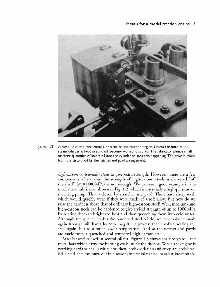
Figure 1.2 A close-up of the mechanical lubricator on the traction engine. Unless the bore of thesteam cylinder is kept oiled it will become worn and scored. The lubricator pumps smallmetered quantities of steam oil into the cylinder to stop this happening. The drive is takenfrom the piston rod by the ratchet and pawl arrangement.
high-carbon or low-alloy steels to give extra strength. However, there are a fewcomponents where even the strength of high-carbon steels as delivered “offthe shelf” (�y ≈ 400 MPa) is not enough. We can see a good example in themechanical lubricator, shown in Fig. 1.2, which is essentially a high-pressure oilmetering pump. This is driven by a ratchet and pawl. These have sharp teethwhich would quickly wear if they were made of a soft alloy. But how do weraise the hardness above that of ordinary high-carbon steel? Well, medium- andhigh-carbon steels can be hardened to give a yield strength of up to 1000 MPaby heating them to bright red heat and then quenching them into cold water.Although the quench makes the hardened steel brittle, we can make it toughagain (though still hard) by tempering it – a process that involves heating thesteel again, but to a much lower temperature. And so the ratchet and pawlsare made from a quenched and tempered high-carbon steel.
Stainless steel is used in several places. Figure 1.3 shows the fire grate – themetal bars which carry the burning coals inside the firebox. When the engine isworking hard the coal is white hot; then, both oxidation and creep are problems.Mild steel bars can burn out in a season, but stainless steel bars last indefinitely.

6 Chapter 1 Metals
Figure 1.3 The fire grate, which carries the white-hot fire inside the firebox, must resist oxidation andcreep. Stainless steel is best for this application. Note also the threaded monel stays whichhold the firebox sides together against the internal pressure of the steam.
Finally, what about cast iron? Although this is rather brittle, it is fine for low-stressed components like the cylinder block. In fact, because cast iron has a lotof carbon it has several advantages over mild steel. Complicated componentslike the cylinder block are best produced by casting. Now cast iron melts muchmore easily than steel (adding carbon reduces the melting point in just theway that adding anti-freeze works with water) and this makes the pouring ofthe castings much easier. During casting, the carbon can be made to separateout as tiny particles of graphite, distributed throughout the iron, which makean ideal boundary lubricant. Cylinders and pistons made from cast iron wearvery well; look inside the cylinders of your car engine next time the head hasto come off, and you will be amazed by the polished, almost glazed look ofthe bores – and this after perhaps 108 piston strokes.
These, then, are the basic classes of ferrous alloys. Their compositions anduses are summarised in Table 1.1, and you will learn more about them inChapters 11 and 12, but let us now look at the other generic alloy groups.
An important group of alloys are those based on copper (Table 1.2).The most notable part of the traction engine made from copper is the boiler
and its firetubes (see Fig. 1.1). In full size this would have been made from
Metals for a model traction engine 7
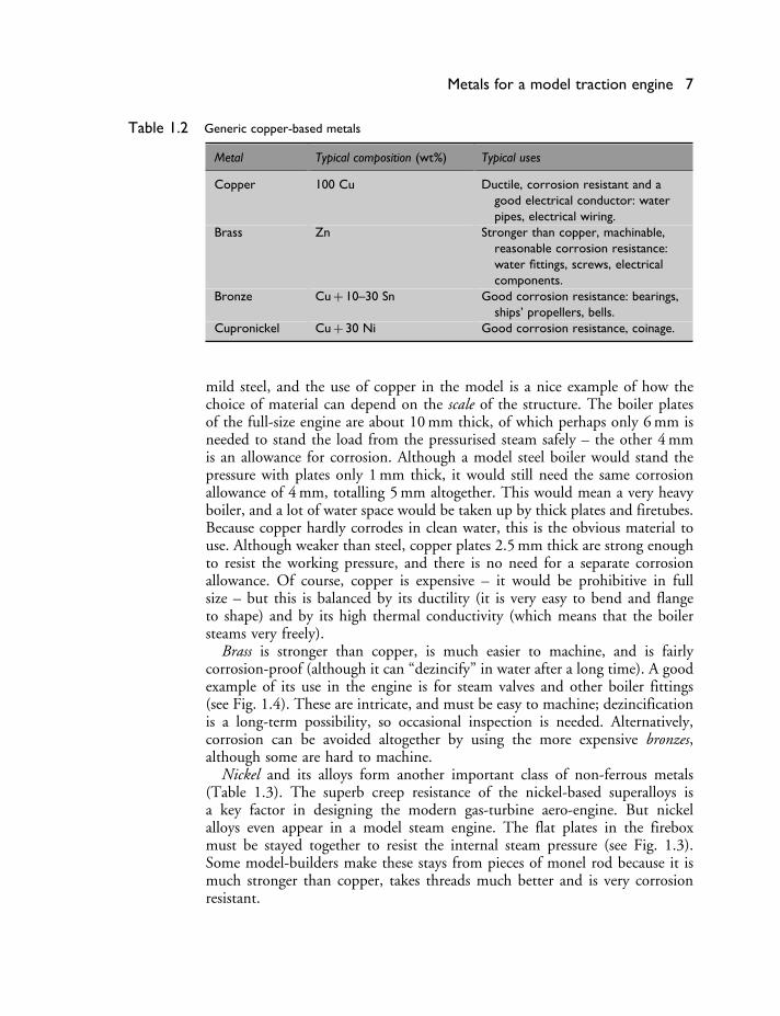
Table 1.2 Generic copper-based metals
Metal Typical composition (wt%) Typical uses
Copper 100 Cu Ductile, corrosion resistant and agood electrical conductor: waterpipes, electrical wiring.
Brass Zn Stronger than copper, machinable,reasonable corrosion resistance:water fittings, screws, electricalcomponents.
Bronze Cu + 10–30 Sn Good corrosion resistance: bearings,ships’ propellers, bells.
Cupronickel Cu + 30 Ni Good corrosion resistance, coinage.
mild steel, and the use of copper in the model is a nice example of how thechoice of material can depend on the scale of the structure. The boiler platesof the full-size engine are about 10 mm thick, of which perhaps only 6 mm isneeded to stand the load from the pressurised steam safely – the other 4 mmis an allowance for corrosion. Although a model steel boiler would stand thepressure with plates only 1 mm thick, it would still need the same corrosionallowance of 4 mm, totalling 5 mm altogether. This would mean a very heavyboiler, and a lot of water space would be taken up by thick plates and firetubes.Because copper hardly corrodes in clean water, this is the obvious material touse. Although weaker than steel, copper plates 2.5 mm thick are strong enoughto resist the working pressure, and there is no need for a separate corrosionallowance. Of course, copper is expensive – it would be prohibitive in fullsize – but this is balanced by its ductility (it is very easy to bend and flangeto shape) and by its high thermal conductivity (which means that the boilersteams very freely).
Brass is stronger than copper, is much easier to machine, and is fairlycorrosion-proof (although it can “dezincify” in water after a long time). A goodexample of its use in the engine is for steam valves and other boiler fittings(see Fig. 1.4). These are intricate, and must be easy to machine; dezincificationis a long-term possibility, so occasional inspection is needed. Alternatively,corrosion can be avoided altogether by using the more expensive bronzes,although some are hard to machine.
Nickel and its alloys form another important class of non-ferrous metals(Table 1.3). The superb creep resistance of the nickel-based superalloys isa key factor in designing the modern gas-turbine aero-engine. But nickelalloys even appear in a model steam engine. The flat plates in the fireboxmust be stayed together to resist the internal steam pressure (see Fig. 1.3).Some model-builders make these stays from pieces of monel rod because it ismuch stronger than copper, takes threads much better and is very corrosionresistant.

8 Chapter 1 Metals
Figure 1.4 Miniature boiler fittings made from brass: a water-level gauge, a steam valve, a pressuregauge, and a feed-water injector. Brass is so easy to machine that it is good for intricateparts like these.
Table 1.3 Generic nickel-based metals
Metals Typical composition (wt%) Typical uses
Monels Ni + 30 Cu 1Fe 1Mn Strong, corrosion resistant:heat-exchanger tubes.
Superalloys Ni + 30 Cr 30 Fe 0.5 Ti 0.5 Al Creep and oxidation resistant:furnace parts.
Ni + 10 Co 10 W 9 Cr 5 A12 Ti Highly creep resistant: turbine bladesand discs.
Metals for drinks cans
Few people would think that the humble drink can (Fig. 1.5) was anythingspecial. But to a materials engineer it is high technology. Look at the require-ments. As far as possible we want to avoid seams. The can must not leak,should use as little metal as possible and be recyclable. We have to choose ametal that is ductile to the point that it can be drawn into a single-piece can
Metals for drinks cans 9
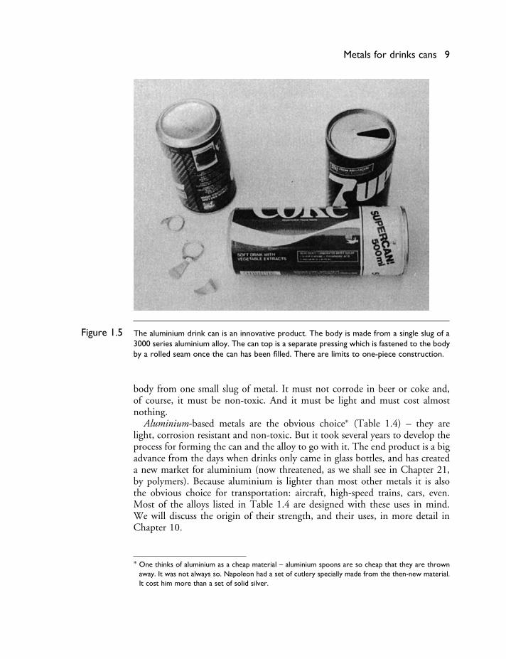
Figure 1.5 The aluminium drink can is an innovative product. The body is made from a single slug of a3000 series aluminium alloy. The can top is a separate pressing which is fastened to the bodyby a rolled seam once the can has been filled. There are limits to one-piece construction.
body from one small slug of metal. It must not corrode in beer or coke and,of course, it must be non-toxic. And it must be light and must cost almostnothing.
Aluminium-based metals are the obvious choice∗ (Table 1.4) – they arelight, corrosion resistant and non-toxic. But it took several years to develop theprocess for forming the can and the alloy to go with it. The end product is a bigadvance from the days when drinks only came in glass bottles, and has createda new market for aluminium (now threatened, as we shall see in Chapter 21,by polymers). Because aluminium is lighter than most other metals it is alsothe obvious choice for transportation: aircraft, high-speed trains, cars, even.Most of the alloys listed in Table 1.4 are designed with these uses in mind.We will discuss the origin of their strength, and their uses, in more detail inChapter 10.
∗ One thinks of aluminium as a cheap material – aluminium spoons are so cheap that they are thrownaway. It was not always so. Napoleon had a set of cutlery specially made from the then-new material.It cost him more than a set of solid silver.

10 Chapter 1 Metals
Table 1.4 Generic aluminium-based metals
Metal Typical composition (wt%) Typical uses
1000 Seriesunalloyed Al
>99 Al Weak but ductile and a goodelectrical conductor: powertransmission lines, cooking foil.
2000 Series majoradditive Cu
Al + 4 Cu + Mg, Si, Mn Strong age-hardening alloy: aircraftskins, spars, forgings, rivets.
3000 Series majoradditive Mn
Al + 1 Mn Moderate strength, ductile, excellentcorrosion resistance: roofingsheet, cooking pans, drinks canbodies.
5000 Series majoradditive Mg
Al + 3 Mg 0.5 Mn Strong work-hardening weldableplate: pressure vessels, shipsuperstructures.
6000 Seriesmajor additivesMg + Si
Al + 0.5 Mg 0.5 Si Moderate-strength age-hardeningalloy: anodised extruded sections,e.g. window frames.
7000 Seriesmajor additivesZn + Mg
Al + 6 Zn + Mg, Cu, Mn Strong age-hardening alloy: aircraftforgings, spars, lightweight railwaycarriage shells.
Casting alloys Al + 11 Si Sand and die castings.Aluminium–
lithium alloysAl + 3 Li Low density and good strength:
aircraft skins and spars.
Metals for artificial hip joints
As a last example we turn to the world of medicine. Osteo-arthritis is an illnessthat affects many people as they get older. The disease affects the joints betweendifferent bones in the body and makes it hard – and painful – to move them.The problem is caused by small lumps of bone which grow on the rubbingsurfaces of the joints and which prevent them sliding properly. The problemcan only be cured by removing the bad joints and putting artificial joints intheir place. The first recorded hip-joint replacement was done as far back as1897 – when it must have been a pretty hazardous business – but the operationis now a routine piece of orthopaedic surgery. In fact half a million hip jointsare replaced world-wide every year.
Figure 1.6 shows the implant for a replacement hip joint. In the operation,the head of the femur is cut off and the soft marrow is taken out to make ahole down the centre of the bone. Into the hole is glued a long metal shankwhich carries the artificial head. This fits into a high-density polythene socketwhich in turn is glued into the old bone socket. The requirements of theimplant are stringent. It has to take large loads without bending. Every timethe joint is used (≈106 times a year) the load on it fluctuates, giving us a
Metals for artificial hip joints 11
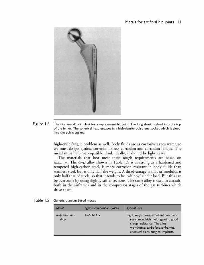
Figure 1.6 The titanium alloy implant for a replacement hip joint. The long shank is glued into the topof the femur. The spherical head engages in a high-density polythene socket which is gluedinto the pelvic socket.
high-cycle fatigue problem as well. Body fluids are as corrosive as sea water, sowe must design against corrosion, stress corrosion and corrosion fatigue. Themetal must be bio-compatible. And, ideally, it should be light as well.
The materials that best meet these tough requirements are based ontitanium. The �–� alloy shown in Table 1.5 is as strong as a hardened andtempered high-carbon steel, is more corrosion resistant in body fluids thanstainless steel, but is only half the weight. A disadvantage is that its modulus isonly half that of steels, so that it tends to be “whippy” under load. But this canbe overcome by using slightly stiffer sections. The same alloy is used in aircraft,both in the airframes and in the compressor stages of the gas turbines whichdrive them.
Table 1.5 Generic titanium-based metals
Metal Typical composition (wt%) Typical uses
�–� titaniumalloy
Ti–6 A14 V Light, very strong, excellent corrosionresistance, high melting point, goodcreep resistance. The alloyworkhorse: turbofans, airframes,chemical plant, surgical implants.

Table 1.6 Properties of the generic metals
Metal Cost(UK£ (US$)tonne−1)
Density(Mg m−3)
Young’smodulus(GPa)
Yieldstrength(MPa)
Tensilestrength(MPa)
Ductility Fracturetoughness(MPa m1/2)
MeltingTemperature(K)
Specificheat( J kg−1K−1)
Thermalconductivity(W m−1K−1)
Thermalexpansioncoefficient(MK−1)
Iron 100 (140) 7.9 211 50 200 0.3 80 1809 456 78 12Mild steel 200–230
(260–300)7.9 210 220 430 0.21 140 1765 482 60 12
High-carbon steel 150 (200) 7.8 210 350–1600 650–2000 0.1–0.2 20–50 1570 460 40 12Low-alloy steels 180–250
(230–330)7.8 203 290–1600 420–2000 0.1–0.2 50–170 1750 460 40 12
High-alloy steels 1100–1400(1400–1800)
7.8 215 170–1600 460–1700 0.1–0.5 50–170 1680 500 12–30 10–18
Cast irons 120 (160) 7.4 152 50–400 10–800 0–0.18 6–20 1403
Copper 1020 (1330) 8.9 130 75 220 0.5–0.9 >100 1356 385 397 17Brasses 750–1060
(980–1380)8.4 105 200 350 0.5 30–100 1190 121 20
Bronzes 1500 (2000) 8.4 120 200 350 0.5 30–100 1120 85 19
Nickel 3200 (4200) 8.9 214 60 300 0.4 >100 1728 450 89 13Monels 3000 (3900) 8.9 185 340 680 0.5 >100 1600 420 22 14Superalloys 5000 (6500) 7.9 214 800 1300 0.2 >100 1550 450 11 12
Aluminium 910 (1180) 2.7 71 25–125 75–135 0.1–0.5 45 933 917 240 241000 Series 910 (1180) 2.7 71 28–165 75–180 0.1–0.45 45 915 242000 Series 1100 (1430) 2.8 71 200–500 300–600 0.1–0.25 10–50 860 180 245000 Series 1000 (1300) 2.7 71 40–300 120–430 0.1–0.35 30–40 890 130 227000 Series 1100 (1430) 2.8 71 350–600 500–670 0.1–0.17 20–70 890 150 24Casting alloys 1100 (1430) 2.7 71 65–350 130–400 0.01–0.15 5–30 860 140 20
Titanium 4630 (6020) 4.5 120 170 240 0.25 1940 530 22 9Ti–6 A14 V 5780 (7510) 4.4 115 800–900 900–1000 0.1–0.2 50–80 1920 610 6 8
Zinc 330 (430) 7.1 105 120 0.4 693 390 120 31Lead–tin solder 2000 (2600) 9.4 40 456Diecasting alloy 800 (1040) 6.7 105 280–330 0.07–0.15 650 420 110 27
Examples 13
Data for metals
When you select a metal for any design application you need data for theproperties. Table 1.6 gives you approximate property data for the main genericmetals, useful for the first phase of a design project. When you have narroweddown your choice you should turn to the more exhaustive data compilationsgiven in Appendix 3. Finally, before making final design decisions you shouldget detailed material specifications from the supplier who will provide thematerials you intend to use. And if the component is a critical one (meaning thatits failure could precipitate a catastrophe) you should arrange to test it yourself.
There are, of course, many more metals available than those listed here. It isuseful to know that some properties depend very little on microstructure: thedensity, modulus, thermal expansion and specific heat of any steel are prettyclose to those listed in the table. (Look at the table and you will see thatthe variations in these properties are seldom more than ±5%.) These are the“structure-insensitive” properties. Other properties, though, vary greatly with theheat treatment and mechanical treatment, and the detailed alloy composition.These are the “structure-sensitive” properties: yield and tensile strength, ductility,fracture toughness, and creep and fatigue strength. They cannot be guessedfrom data for other alloys, even when the composition is almost the same. Forthese it is essential to consult manufacturers’ data sheets listing the propertiesof the alloy you intend to use, with the same mechanical and heat treatment.
Examples
1.1 Explain what is meant by the following terms:
(a) structure-sensitive property;(b) structure-insensitive property.
List five different structure-sensitive properties.List four different structure-insensitive properties.
Answers
Structure-sensitive properties: yield strength, hardness, tensile strength, ductility,fracture toughness, fatigue strength, creep strength, corrosion resistance, wearresistance, thermal conductivity, electrical conductivity. Structure-insensitiveproperties: elastic moduli, Poisson’s ratio, density, thermal expansion coeffi-cient, specific heat.
1.2 What are the five main generic classes of metals? For each generic class:
(a) give one example of a specific component made from that class;(b) indicate why that class was selected for the component.

Chapter 2Metal structures
Introduction
At the end of Chapter 1 we noted that structure-sensitive properties likestrength, ductility or toughness depend critically on things like the compo-sition of the metal and on whether it has been heated, quenched or coldformed. Alloying or heat treating work by controlling the structure of themetal. Table 2.1 shows the large range over which a material has structure.The bracketed subset in the table can be controlled to give a wide choice ofstructure-sensitive properties.
Crystal and glass structures
We begin by looking at the smallest scale of controllable structural feature –the way in which the atoms in the metals are packed together to give eithera crystalline or a glassy (amorphous) structure. Table 2.2 lists the crystalstructures of the pure metals at room temperature. In nearly every case themetal atoms pack into the simple crystal structures of face-centred cubic (f.c.c),body-centred cubic (b.c.c.) or close-packed hexagonal (c.p.h.).
Metal atoms tend to behave like miniature ball-bearings and tend to packtogether as tightly as possible. F.c.c. and c.p.h. give the highest possible packingdensity, with 74% of the volume of the metal taken up by the atomic spheres.However, in some metals, like iron or chromium, the metallic bond has somedirectionality and this makes the atoms pack into the more open b.c.c. structurewith a packing density of 68%.
Table 2.1
Structural feature Typical scale (m)
Nuclear structure 10−15
Structure of atom 10−10
Crystal or glass structure 10−9
Structures of solutions and compounds 10−9
Structures of grain and phase boundaries 10−8
Shapes of grains and phases 10−7 to 10−3
Range that can be
Aggregates of grains 10−5 to 10−2
controlled to alter
Engineering structures 10−3 to 103
⎫⎪⎪⎪⎪⎬⎪⎪⎪⎪⎭ properties
14

Crystal and glass structures 15
Table 2.2 Crystal structures of pure metals at room temperature
Pure metal Structure Unit cell dimensions (nm)
a c
Aluminium f.c.c. 0.405Beryllium c.p.h. 0.229 0.358Cadmium c.p.h. 0.298 0.562Chromium b.c.c. 0.289Cobalt c.p.h. 0.251 0.409Copper f.c.c. 0.362Gold f.c.c. 0.408Hafnium c.p.h. 0.320 0.506Indium Face-centred tetragonalIridium f.c.c. 0.384Iron b.c.c. 0.287Lanthanum c.p.h. 0.376 0.606Lead f.c.c. 0.495Magnesium c.p.h. 0.321 0.521Manganese Cubic 0.891Molybdenum b.c.c. 0.315Nickel f.c.c. 0.352Niobium b.c.c. 0.330Palladium f.c.c. 0.389Platinum f.c.c. 0.392Rhodium f.c.c. 0.380Silver f.c.c. 0.409Tantalum b.c.c. 0.331Thallium c.p.h. 0.346 0.553Tin Body-centred tetragonalTitanium c.p.h. 0.295 0.468Tungsten b.c.c. 0.317Vanadium b.c.c. 0.303Yttrium c.p.h. 0.365 0.573Zinc c.p.h. 0.267 0.495Zirconium c.p.h. 0.323 0.515
Some metals have more than one crystal structure. The most importantexamples are iron and titanium. As Fig. 2.1 shows, iron changes from b.c.c.to f.c.c. at 914�C but goes back to b.c.c. at 1391�C; and titanium changesfrom c.p.h. to b.c.c. at 882�C. This multiplicity of crystal structures is calledpolymorphism. But it is obviously out of the question to try to control crystalstructure simply by changing the temperature (iron is useless as a structuralmaterial well below 914�C). Polymorphism can, however, be brought aboutat room temperature by alloying. Indeed, many stainless steels are f.c.c. ratherthan b.c.c. and, especially at low temperatures, have much better ductility andtoughness than ordinary carbon steels.