Embed Size (px)
Citation preview
Eng
lish
Deu
tsch
Fran
çais
Esp
añol
Port
uguê
sIt
alia
noРусски
й日本語
Owner’s ManualBedienungsanleitungMode d’emploiManual de instruccionesManual do ProprietárioManuale di istruzioniРуководство пользователя
取扱説明書JA
ZH
RU
IT
PT
ES
FR
DE
EN
Owner’s Manual2
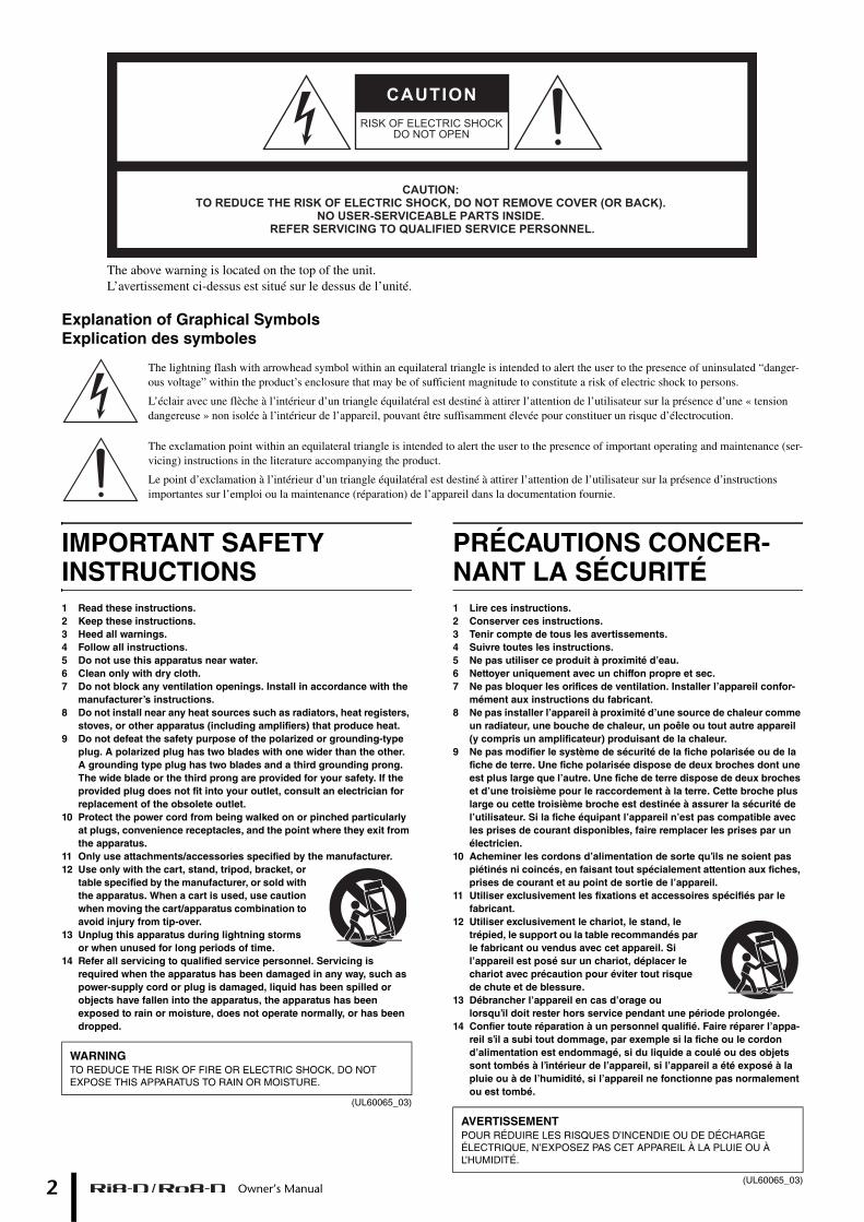
The above warning is located on the top of the unit.L’avertissement ci-dessus est situé sur le dessus de l’unité.
Explanation of Graphical SymbolsExplication des symboles
The lightning flash with arrowhead symbol within an equilateral triangle is intended to alert the user to the presence of uninsulated “danger-ous voltage” within the product’s enclosure that may be of sufficient magnitude to constitute a risk of electric shock to persons.
L’éclair avec une flèche à l’intérieur d’un triangle équilatéral est destiné à attirer l’attention de l’utilisateur sur la présence d’une « tension dangereuse » non isolée à l’intérieur de l’appareil, pouvant être suffisamment élevée pour constituer un risque d’électrocution.
The exclamation point within an equilateral triangle is intended to alert the user to the presence of important operating and maintenance (ser-vicing) instructions in the literature accompanying the product.
Le point d’exclamation à l’intérieur d’un triangle équilatéral est destiné à attirer l’attention de l’utilisateur sur la présence d’instructions importantes sur l’emploi ou la maintenance (réparation) de l’appareil dans la documentation fournie.
IMPORTANT SAFETY INSTRUCTIONS1 Read these instructions.2 Keep these instructions.3 Heed all warnings.4 Follow all instructions.5 Do not use this apparatus near water.6 Clean only with dry cloth.7 Do not block any ventilation openings. Install in accordance with the
manufacturer’s instructions.8 Do not install near any heat sources such as radiators, heat registers,
stoves, or other apparatus (including amplifiers) that produce heat.9 Do not defeat the safety purpose of the polarized or grounding-type
plug. A polarized plug has two blades with one wider than the other. A grounding type plug has two blades and a third grounding prong. The wide blade or the third prong are provided for your safety. If the provided plug does not fit into your outlet, consult an electrician for replacement of the obsolete outlet.
10 Protect the power cord from being walked on or pinched particularly at plugs, convenience receptacles, and the point where they exit from the apparatus.
11 Only use attachments/accessories specified by the manufacturer.12 Use only with the cart, stand, tripod, bracket, or
table specified by the manufacturer, or sold with the apparatus. When a cart is used, use caution when moving the cart/apparatus combination to avoid injury from tip-over.
13 Unplug this apparatus during lightning storms or when unused for long periods of time.
14 Refer all servicing to qualified service personnel. Servicing is required when the apparatus has been damaged in any way, such as power-supply cord or plug is damaged, liquid has been spilled or objects have fallen into the apparatus, the apparatus has been exposed to rain or moisture, does not operate normally, or has been dropped.
(UL60065_03)
PRÉCAUTIONS CONCER-NANT LA SÉCURITÉ1 Lire ces instructions.2 Conserver ces instructions.3 Tenir compte de tous les avertissements.4 Suivre toutes les instructions.5 Ne pas utiliser ce produit à proximité d’eau.6 Nettoyer uniquement avec un chiffon propre et sec.7 Ne pas bloquer les orifices de ventilation. Installer l’appareil confor-
mément aux instructions du fabricant.8 Ne pas installer l’appareil à proximité d’une source de chaleur comme
un radiateur, une bouche de chaleur, un poêle ou tout autre appareil (y compris un amplificateur) produisant de la chaleur.
9 Ne pas modifier le système de sécurité de la fiche polarisée ou de la fiche de terre. Une fiche polarisée dispose de deux broches dont une est plus large que l’autre. Une fiche de terre dispose de deux broches et d’une troisième pour le raccordement à la terre. Cette broche plus large ou cette troisième broche est destinée à assurer la sécurité de l’utilisateur. Si la fiche équipant l’appareil n’est pas compatible avec les prises de courant disponibles, faire remplacer les prises par un électricien.
10 Acheminer les cordons d’alimentation de sorte qu’ils ne soient pas piétinés ni coincés, en faisant tout spécialement attention aux fiches, prises de courant et au point de sortie de l’appareil.
11 Utiliser exclusivement les fixations et accessoires spécifiés par le fabricant.
12 Utiliser exclusivement le chariot, le stand, le trépied, le support ou la table recommandés par le fabricant ou vendus avec cet appareil. Si l’appareil est posé sur un chariot, déplacer le chariot avec précaution pour éviter tout risque de chute et de blessure.
13 Débrancher l’appareil en cas d’orage ou lorsqu’il doit rester hors service pendant une période prolongée.
14 Confier toute réparation à un personnel qualifié. Faire réparer l’appa-reil s’il a subi tout dommage, par exemple si la fiche ou le cordon d’alimentation est endommagé, si du liquide a coulé ou des objets sont tombés à l’intérieur de l’appareil, si l’appareil a été exposé à la pluie ou à de l’humidité, si l’appareil ne fonctionne pas normalement ou est tombé.
(UL60065_03)
WARNINGTO REDUCE THE RISK OF FIRE OR ELECTRIC SHOCK, DO NOT EXPOSE THIS APPARATUS TO RAIN OR MOISTURE.
AVERTISSEMENTPOUR RÉDUIRE LES RISQUES D’INCENDIE OU DE DÉCHARGE ÉLECTRIQUE, N’EXPOSEZ PAS CET APPAREIL À LA PLUIE OU À L’HUMIDITÉ.
1. IMPORTANT NOTICE: DO NOT MODIFY THIS UNIT! not guarantee that interference will not occur in all installations. If
FCC INFORMATION (U.S.A.)
This product, when installed as indicated in the instructions con-tained in this manual, meets FCC requirements. Modifications not expressly approved by Yamaha may void your authority, granted by the FCC, to use the product.2. IMPORTANT: When connecting this product to accessories and/or another product use only high quality shielded cables. Cable/s supplied with this product MUST be used. Follow all installation instructions. Failure to follow instructions could void your FCC authorization to use this product in the USA.
3. NOTE: This product has been tested and found to comply with the requirements listed in FCC Regulations, Part 15 for Class “B” digital devices. Compliance with these requirements provides a reason-able level of assurance that your use of this product in a residential environment will not result in harmful interference with other elec-tronic devices. This equipment generates/uses radio frequencies and, if not installed and used according to the instructions found in the users manual, may cause interference harmful to the operation of other electronic devices. Compliance with FCC regulations does
this product is found to be the source of interference, which can be determined by turning the unit “OFF” and “ON”, please try to elimi-nate the problem by using one of the following measures:Relocate either this product or the device that is being affected by the interference. Utilize power outlets that are on different branch (circuit breaker or fuse) circuits or install AC line filter/s.In the case of radio or TV interference, relocate/reorient the antenna. If the antenna lead-in is 300 ohm ribbon lead, change the lead-in to co-axial type cable.If these corrective measures do not produce satisfactory results, please contact the local retailer authorized to distribute this type of product. If you can not locate the appropriate retailer, please contact Yamaha Corporation of America, Electronic Service Division, 6600 Orangethorpe Ave, Buena Park, CA90620The above statements apply ONLY to those products distributed by Yamaha Corporation of America or its subsidiaries.
* This applies only to products distributed by YAMAHA CORPORATION OF AMERICA. (class B)
orea)
IMPORTANT NOTICE FOR THE UNITED KINGDOMConnecting the Plug and Cord
WARNING: THIS APPARATUS MUST BE EARTHED IMPORTANT. The wires in this mains lead are coloured in accordance with the fol-lowing code:
GREEN-AND-YELLOW : EARTHBLUE : NEUTRALBROWN : LIVE
As the colours of the wires in the mains lead of this apparatus may not correspond with the coloured markings identifying the terminals in your plug proceed as follows:The wire which is coloured GREEN-and-YELLOW must be connected to the terminal in the plug which is marked by the letter E or by the safety earth symbol or colored GREEN or GREEN-and-YELLOW.The wire which is coloured BLUE must be connected to the terminal which is marked with the letter N or coloured BLACK.The wire which is coloured BROWN must be connected to the terminal which is marked with the letter L or coloured RED.
(3 wires)
COMPLIANCE INFORMATION STATEMENT(DECLARATION OF CONFORMITY PROCEDURE)
Responsible Party : Yamaha Corporation of AmericaAddress : 6600 Orangethorpe Ave., Buena Park, Calif. 90620
Telephone : 714-522-9011Type of Equipment : I/O RACK
Model Name : Ri8-D/Ro8-D
This device complies with Part 15 of the FCC Rules.Operation is subject to the following two conditions:1) this device may not cause harmful interference, and2) this device must accept any interference received including interference
that may cause undesired operation.See user manual instructions if interference to radio reception is suspected.
* This applies only to products distributed by YAMAHA CORPORATION OF AMERICA.
(FCC DoC)
(class b k
Owner’s Manual 3

4
Owner’s Manual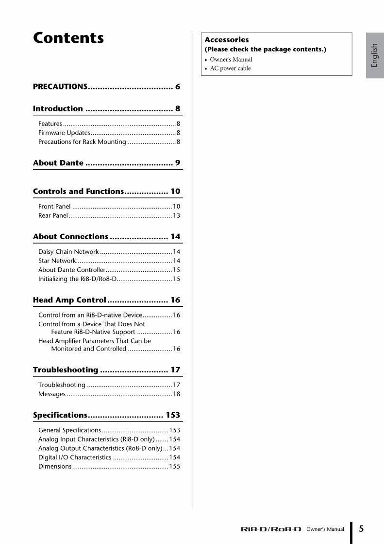
Engl
ish
Owner’s Manual 5
Contents
PRECAUTIONS................................... 6
Introduction .................................... 8
Features .............................................................8Firmware Updates..............................................8Precautions for Rack Mounting ..........................8
About Dante .................................... 9
Controls and Functions.................. 10
Front Panel ......................................................10Rear Panel........................................................13
About Connections ........................ 14
Daisy Chain Network .......................................14Star Network....................................................14About Dante Controller....................................15Initializing the Ri8-D/Ro8-D..............................15
Head Amp Control ......................... 16
Control from an Ri8-D-native Device................16Control from a Device That Does Not
Feature Ri8-D-Native Support ...................16Head Amplifier Parameters That Can be
Monitored and Controlled ........................16
Troubleshooting ............................ 17
Troubleshooting ..............................................17Messages .........................................................18
Specifications............................... 153
General Specifications ....................................153Analog Input Characteristics (Ri8-D only) .......154Analog Output Characteristics (Ro8-D only)...154Digital I/O Characteristics ..............................154Dimensions....................................................155
Accessories(Please check the package contents.)
• Owner’s Manual• AC power cable
6
PRECAUTIONSPLEASE READ CAREFULLY BEFORE PROCEEDING
* Please keep this manual in a safe place for future reference.
WARNINGAlways follow the basic precautions listed below to avoid the possibility of serious injury or even death from electrical shock, short-circuiting, damages, fire or other hazards. These precautions include, but are not limited to, the following:
• Do not place the power cord near heat sources such as heaters or radiators, and do not excessively bend or otherwise damage the cord, place heavy objects on it, or place it in a position where anyone could walk on, trip over, or roll anything over it.
• Only use the voltage specified as correct for the device. The required voltage is printed on the name plate of the device.
• Use only the supplied power cord/plug.If you intend to use the device in an area other than in the one you purchased, the included power cord may not be compatible. Please check with your Yamaha dealer.
• Check the electric plug periodically and remove any dirt or dust which may have accumulated on it.
• Be sure to connect to an appropriate outlet with a protective grounding connection. Improper grounding can result in electrical shock.
• This device contains no user-serviceable parts. Do not open the device or attempt to disassemble the internal parts or modify them in any way. If it should appear to be malfunctioning, discontinue use immediately and have it inspected by qualified Yamaha service personnel.
• Do not expose the device to rain, use it near water or in damp or wet conditions, or place on it any containers (such as vases, bottles or glasses) containing liquids which might spill into any openings. If any liquid such as water seeps into the device, turn off the power immediately and unplug the power cord from the AC outlet. Then have the device inspected by qualified Yamaha service personnel.
• Never insert or remove an electric plug with wet hands.
• Do not put burning items, such as candles, on the unit. A burning item may fall over and cause a fire.
• When one of the following problems occur, immediately turn off the power switch and disconnect the electric plug from the outlet. Then have the device inspected by Yamaha service personnel.- The power cord or plug becomes frayed or damaged.- It emits unusual smells or smoke.- Some object has been dropped into the instrument.- There is a sudden loss of sound during use of the device.
• If this device should be dropped or damaged, immediately turn off the power switch, disconnect the electric plug from the outlet, and have the device inspected by qualified Yamaha service personnel.
CAUTIONAlways follow the basic precautions listed below to avoid the possibility of physical injury to you or others, or damage to the device or other property. These precautions include, but are not limited to, the following:
• When removing the electric plug from the device or an outlet, always hold the plug itself and not the cord. Pulling by the cord can damage it.
• Remove the electric plug from the outlet when the device is not to be used for extended periods of time, or during electrical storms.
• Do not place the device in an unstable position where it might accidentally fall over.
• Do not block the vents. This device has ventilation holes at the front and side to prevent the internal temperature from becoming too high. In particular, do not place the device on its side or upside down. Inadequate ventilation can result in overheating, possibly causing damage to the device(s), or even fire.
• To avoid damage, do not install or store the device in a place subject to salty air or corrosive gas or chemicals.
• Before moving the device, remove all connected cables.
• When setting up the device, make sure that the AC outlet you are using is easily accessible. If some trouble or malfunction occurs, immediately turn off the power switch and disconnect the plug from the outlet. Even when the power switch is turned off, electricity is still flowing to the product at the minimum level. When you are not using the product for a long time, make sure to unplug the power cord from the wall AC outlet.
• If the device is mounted in an EIA standard rack, carefully read the section “Precautions for Rack Mounting” on page 8. Inadequate ventilation can result in overheating, possibly causing damage to the device(s), malfunction, or even fire.
• Keep device away from the reach of children.
• Before connecting the device to other devices, turn off the power for all devices. Before turning the power on or off for all devices, set all volume levels to minimum.
• Remove the power plug from the AC outlet when cleaning the device.
• Do not insert your fingers or hands in any gaps or openings on the device (vents, etc.).
• Avoid inserting or dropping foreign objects (paper, plastic, metal, etc.) into any gaps or openings on the device (vents, etc.) If this happens, turn off the power immediately and unplug the power cord from the AC outlet. Then have the device inspected by qualified Yamaha service personnel.
• Do not rest your weight on the device or place heavy objects on it, and avoid use excessive force on the buttons, switches or connectors.
• Do not use speakers for a long period of time at a high or uncomfortable volume level, since this can cause permanent hearing loss. If you experience any hearing loss or ringing in the ears, consult a physician.
Power supply/Power cord
Do not open
Water warning
Fire warning
If you notice any abnormality
Power supply/Power cord
Location
Connections
Maintenance
Handling caution
Owner’s Manual
PA_en_1 1/2
Engl
ish
NOTICETo avoid the possibility of malfunction/ damage to the product, damage to data, or damage to other property, follow the notices below.
• Do not use the device in the vicinity of a TV, radio, stereo equipment, mobile phone, or other electric devices. Otherwise, the device, TV, or radio may generate noise.
• Do not expose the device to excessive dust or vibrations, or extreme cold or heat (such as in direct sunlight, near a heater, or in a car during the day) to prevent the possibility of panel disfiguration, damage to the internal components or unstable operation.
• Do not place vinyl, plastic or rubber objects on the device, since this might discolor the panel or keyboard.
• When cleaning the device, use a dry and soft cloth. Do not use paint thinners, solvents, cleaning fluids, or chemical-impregnated wiping cloths.
• Condensation can occur in the device due to rapid, drastic changes in ambient temperature—when the device is moved from one location to another, or air conditioning is turned on or off, for example. Using the device while condensation is present can cause damage. If there is reason to believe that condensation might have occurred, leave the device for several hours without turning on the power until the condensation has completely dried out.
• Always turn the power off when the device is not in use.
• XLR-type connectors are wired as follows (IEC60268 standard): pin 1: ground, pin 2: hot (+), and pin 3: cold (-).
InformationAbout copyrights
* Copying of the commercially available musical data including but not limited to MIDI data and/or audio data is strictly prohibited except for your personal use.
About this manual
* The illustrations and LCD screens as shown in this manual are for instructional purposes only, and may appear somewhat different from those on your device.
* The company names and product names in this manual are the trademarks or registered trademarks of their respective companies.
* Specifications and exterior appearance may be subject to change without prior notice as a result of improvements.
(weee_eu)
Yamaha cannot be held responsible for damage caused by improper use or modifications to the device, or data that is lost or destroyed.
European ModelsInrush Current based on EN 55103-1:20092A (on initial switch-on)2A (after a supply interruption of 5s)Conforms to Environments: E1, E2, E3 and E4
Handling and Maintenance
Connectors
Information for Users on Collection and Disposal of Old Equipment
This symbol on the products, packaging, and/or accompanying documents means that used electrical and electronic products should not be mixed with general household waste.
For proper treatment, recovery and recycling of old products, please take them to applicable collection points, in accordance with your national legislation and the Directives 2002/96/EC.
By disposing of these products correctly, you will help to save valuable resources and prevent any potential negative effects on human health and the environment which could otherwise arise from inappropriate waste handling.
For more information about collection and recycling of old products, please contact your local municipality, your waste disposal service or the point of sale where you purchased the items.
[For business users in the European Union]
If you wish to discard electrical and electronic equipment, please contact your dealer or supplier for further information.
[Information on Disposal in other Countries outside the European Union]
This symbol is only valid in the European Union. If you wish to discard these items, please contact your local authorities or dealer and ask for the correct method of disposal.
Owner’s Manual 7PA_en_1 2/2
Introduction
8
IntroductionThank you for choosing the Yamaha Input Rack Ri8-D/Output Rack Ro8-D. The Ri8-D is a Dante-compatible input rack equipped with 8 channels analog input. The Ro8-D is a Dante-compatible output rack equipped with 8 channels analog output.To take full advantage of the superior functions and performance offered by the Ri8-D/Ro8-D, and to extend the useful life of the product, be sure to read this owner’s manual carefully before operation.
Features
Long-distance Dante Network CapabilityLow-latency, low-jitter audio can be transferred over distances up to 100 meters* between devices via standard Ethernet cables using the Dante network protocol. The Ri8-D/Ro8-D can be used as a general-purpose I/O box for the Dante network. Supported sampling rates are 44.1 kHz, 48 kHz, 88.2 kHz, and 96 kHz.
* Maximum practical distance may vary according to the cable used.
Vast variety of layout is available with compact 1U chassisThe Ri8-D is dedicated for input rack and the Ro8-D is for output. This enables an installation of rack for an occasion requires input only or output only.Of course, combination with the Rio3224-D/Rio1608-D (input/output rack) is enabled to realize system configuration with higher flexibility.
Remotely Controllable Internal Head Amplifiers (Ri8-D only)Internal head amplifier parameters can be remotely controlled from a compatible device, such as the CL series, or from a computer application “R Remote.”
Gain Compensation Function (Ri8-D only)Enabling Gain Compensation feature of the Ri8-D for supporting equipment with gain compensation capability such as CL Series products may compensate change of analog gain in downstream by the compensation gain integrated in the Ri8-D, and it will send the audio signal to Dante network with gain level fixed to a value immediately before it was enabled.
Direct Audio In/Out With a Connected ComputerConnecting the Ri8-D/Ro8-D with a standard Ethernet cable to a computer that has a Dante Virtual Soundcard installed enables you to directly input or output audio signals without using an audio interface device (the Ri8-D is for input and the Ro8-D is for output only).
Firmware UpdatesThis product enables you to update the unit firmware to improve operations, add functions, and correct possible malfunctions. The following two types of firmware are available for the unit.• Unit’s firmware• Dante module firmware
Details on updating the firmware are available on the following website:
http://www.yamahaproaudio.com/
For information on updating and setting up the unit, please refer to the firmware update guide available on the website.
NOTEWhen you update Dante firmware on the unit, be sure to update Dante firmware on other Dante-compatible devices connected to the Ri8-D/Ro8-D.
Precautions for Rack MountingThis unit is rated for operation at ambient temperatures ranging from 0 to 40 degrees Celsius. When mounting the unit with other Ri8-D/Ro8-D unit(s) or other device(s) in an EIA standard equipment rack, internal temperatures can exceed the specified upper limit, resulting in impaired performance or failure. When rack mounting the unit, always observe the following requirements to avoid heat buildup:
• When mounting the unit in a rack with devices such as power amplifiers that generate a significant amount of heat, leave more than 1U of space between the Ri8-D/Ro8-D and other equipment. Also either leave the open spaces uncovered or install appropriate ventilating panels to minimize the possibility of heat buildup.
• To ensure sufficient airflow, leave the rear of the rack open and position it at least 10 centimeters from walls or other surfaces. If the rear of the rack can’t be left open, install a commercially available fan or similar ventilating option to secure sufficient airflow. If you’ve installed a fan kit, there may be cases in which closing the rear of the rack will produce a greater cooling effect. Refer to the rack and/or fan unit manual for details.
Owner’s Manual
Engl
ish
About Dante
About DanteThis product features Dante technology as a protocol to transmit audio signals. Dante is a network protocol developed by Audinate. It is designed to deliver multi-channel audio signals at various sampling and bit rates, as well as device control signals over a Giga-bit Ethernet (GbE) network. Dante also offers the following benefits:• It transmits up to 512 in/512 out, for a total 1024
channels (in theory) of audio over a GbE network. (The Ri8-D features 8 in with a 24/32-bit resolution. The Ro8-D features 8 out with a 24/32-bit resolution.)
• Dante-enabled devices will automatically configure their network interfaces and find each other on the network. You can label Dante devices and their audio channels with names that make sense to you.
• Dante uses high accuracy network synchronization standards to achieve sample-accurate playback with extremely low latency and jitter. Five types of latency are available on the Ri8-D/Ro8-D: 0.25 msec, 0.5 msec, 1.0 msec, 2.0 msec, and 5.0 msec.
• Dante supports redundant connections via primary and secondary networks to defend against unforeseen difficulties.
• Connecting a computer to Dante network over Ethernet enables you to directly input or output audio signals without using any audio interface devices.
By taking advantages of these benefits, you can skip any complicated procedures to automate connections and setups of Dante-enabled devices, remotely control I/O racks or amplifiers from a mixing console, or make multi-track recordings to a DAW, such as Nuendo, installed on a computer in the network.
Visit Audinate website for more details on Dante.http://www.audinate.com/
More information on Dante is also posted on the Yamaha Pro Audio website:
http://www.yamahaproaudio.com/
NOTEPlease do not use the EEE function (*) of network switches in a Dante network.Although power management should be negotiated automatically in switches that support EEE, some switches do not perform the negotiation properly. This may cause EEE to be enabled in Dante networks when it is not appropriate, resulting in poor synchronization performance and occasional dropouts.Therefore we strongly recommend that:• If you use managed switches, ensure that they allow EEE to be
disabled. Make sure that EEE is disabled on all ports used for real-time Dante traffic.
• If you use unmanaged switches, make sure to not use network switches that support the EEE function, since EEE operation cannot be disabled in these switches.
* EEE (Energy Efficient Ethernet) is a technology that reduces switch power consumption during periods of low network traffic. It is also known as Green Ethernet and IEEE802.3az.
Owner’s Manual 9
Controls and Functions
10
Controls and Functions
Front Panel
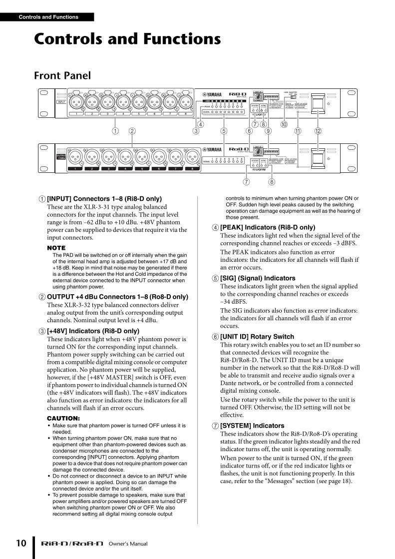
1 [INPUT] Connectors 1–8 (Ri8-D only)These are the XLR-3-31 type analog balanced connectors for the input channels. The input level range is from –62 dBu to +10 dBu. +48V phantom power can be supplied to devices that require it via the input connectors.NOTE
The PAD will be switched on or off internally when the gain of the internal head amp is adjusted between +17 dB and +18 dB. Keep in mind that noise may be generated if there is a difference between the Hot and Cold impedance of the external device connected to the INPUT connector when using phantom power.
2OUTPUT +4 dBu Connectors 1–8 (Ro8-D only)These XLR-3-32 type balanced connectors deliver analog output from the unit’s corresponding output channels. Nominal output level is +4 dBu.
3 [+48V] Indicators (Ri8-D only)These indicators light when +48V phantom power is turned ON for the corresponding input channels. Phantom power supply switching can be carried out from a compatible digital mixing console or computer application. No phantom power will be supplied, however, if the [+48V MASTER] switch is OFF, even if phantom power to individual channels is turned ON (the +48V indicators will flash). The +48V indicators also function as error indicators: the indicators for all channels will flash if an error occurs.CAUTION:• Make sure that phantom power is turned OFF unless it is
needed.• When turning phantom power ON, make sure that no
equipment other than phantom-powered devices such as condenser microphones are connected to the corresponding [INPUT] connectors. Applying phantom power to a device that does not require phantom power can damage the connected device.
• Do not connect or disconnect a device to an INPUT while phantom power is applied. Doing so can damage the connected device and/or the unit itself.
• To prevent possible damage to speakers, make sure that power amplifiers and/or powered speakers are turned OFF when switching phantom power ON or OFF. We also recommend setting all digital mixing console output
controls to minimum when turning phantom power ON or OFF. Sudden high level peaks caused by the switching operation can damage equipment as well as the hearing of those present.
4 [PEAK] Indicators (Ri8-D only)These indicators light red when the signal level of the corresponding channel reaches or exceeds –3 dBFS.The PEAK indicators also function as error indicators: the indicators for all channels will flash if an error occurs.
5 [SIG] (Signal) IndicatorsThese indicators light green when the signal applied to the corresponding channel reaches or exceeds –34 dBFS.The SIG indicators also function as error indicators: the indicators for all channels will flash if an error occurs.
6 [UNIT ID] Rotary SwitchThis rotary switch enables you to set an ID number so that connected devices will recognize the Ri8-D/Ro8-D. The UNIT ID must be a unique number in the network so that the Ri8-D/Ro8-D will be able to transmit and receive audio signals over a Dante network, or be controlled from a connected digital mixing console.Use the rotary switch while the power to the unit is turned OFF. Otherwise, the ID setting will not be effective.
7 [SYSTEM] IndicatorsThese indicators show the Ri8-D/Ro8-D’s operating status. If the green indicator lights steadily and the red indicator turns off, the unit is operating normally.When power to the unit is turned ON, if the green indicator turns off, or if the red indicator lights or flashes, the unit is not functioning properly. In this case, refer to the “Messages” section (see page 18).
1 1 2 3 4 5 6 7 8ON
1 2 3 4 5 6 7 8ON
1
1 2 B34
5 A0
7 8
786 9
Owner’s Manual
Engl
ish
Front Panel
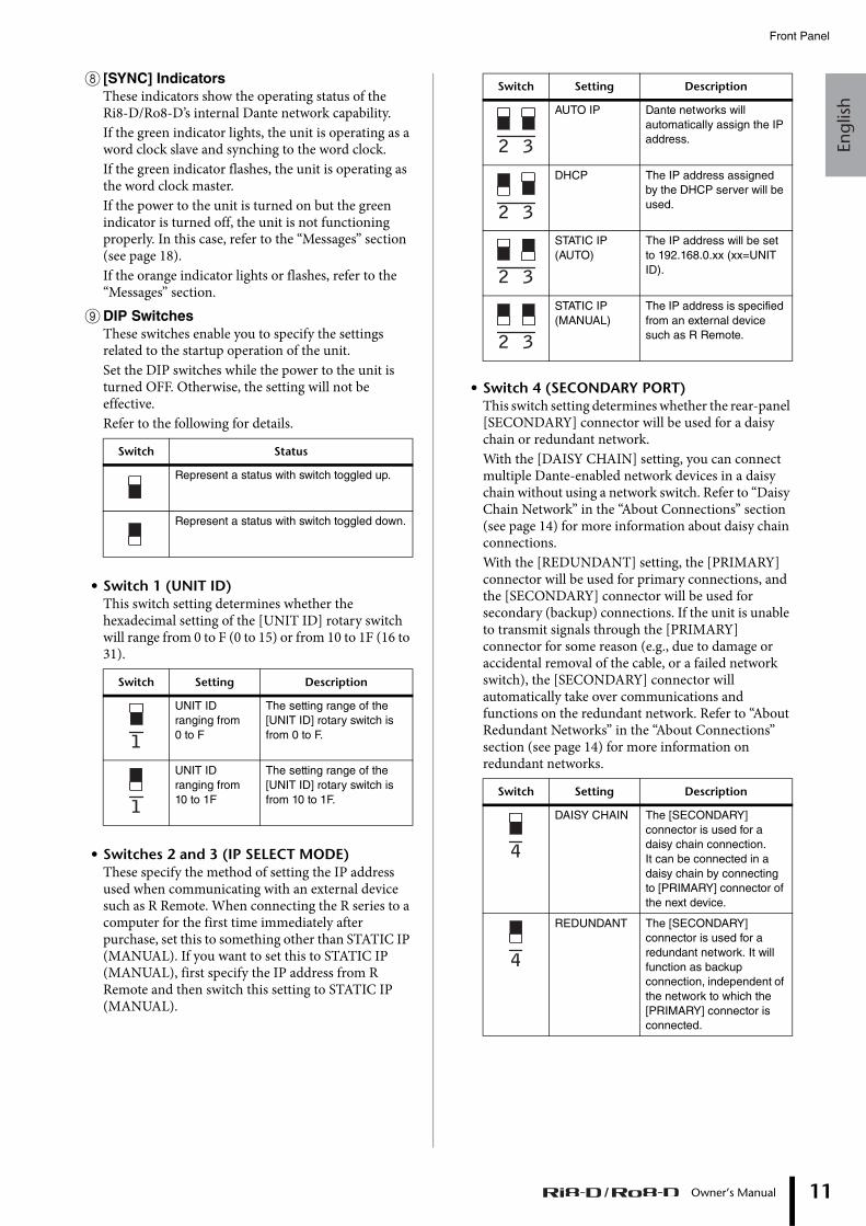
8 [SYNC] IndicatorsThese indicators show the operating status of the Ri8-D/Ro8-D’s internal Dante network capability.If the green indicator lights, the unit is operating as a word clock slave and synching to the word clock.If the green indicator flashes, the unit is operating as the word clock master.If the power to the unit is turned on but the green indicator is turned off, the unit is not functioning properly. In this case, refer to the “Messages” section (see page 18).If the orange indicator lights or flashes, refer to the “Messages” section.
9DIP SwitchesThese switches enable you to specify the settings related to the startup operation of the unit.Set the DIP switches while the power to the unit is turned OFF. Otherwise, the setting will not be effective.Refer to the following for details.
• Switch 1 (UNIT ID)This switch setting determines whether the hexadecimal setting of the [UNIT ID] rotary switch will range from 0 to F (0 to 15) or from 10 to 1F (16 to 31).
• Switches 2 and 3 (IP SELECT MODE)These specify the method of setting the IP address used when communicating with an external device such as R Remote. When connecting the R series to a computer for the first time immediately after purchase, set this to something other than STATIC IP (MANUAL). If you want to set this to STATIC IP (MANUAL), first specify the IP address from R Remote and then switch this setting to STATIC IP (MANUAL).
• Switch 4 (SECONDARY PORT)This switch setting determines whether the rear-panel [SECONDARY] connector will be used for a daisy chain or redundant network.With the [DAISY CHAIN] setting, you can connect multiple Dante-enabled network devices in a daisy chain without using a network switch. Refer to “Daisy Chain Network” in the “About Connections” section (see page 14) for more information about daisy chain connections.With the [REDUNDANT] setting, the [PRIMARY] connector will be used for primary connections, and the [SECONDARY] connector will be used for secondary (backup) connections. If the unit is unable to transmit signals through the [PRIMARY] connector for some reason (e.g., due to damage or accidental removal of the cable, or a failed network switch), the [SECONDARY] connector will automatically take over communications and functions on the redundant network. Refer to “About Redundant Networks” in the “About Connections” section (see page 14) for more information on redundant networks.
Switch Status
Represent a status with switch toggled up.
Represent a status with switch toggled down.
Switch Setting Description
UNIT ID ranging from 0 to F
The setting range of the [UNIT ID] rotary switch is from 0 to F.
UNIT ID ranging from 10 to 1F
The setting range of the [UNIT ID] rotary switch is from 10 to 1F.
1
1
Switch Setting Description
AUTO IP Dante networks will automatically assign the IP address.
DHCP The IP address assigned by the DHCP server will be used.
STATIC IP (AUTO)
The IP address will be set to 192.168.0.xx (xx=UNIT ID).
STATIC IP (MANUAL)
The IP address is specified from an external device such as R Remote.
Switch Setting Description
DAISY CHAIN The [SECONDARY] connector is used for a daisy chain connection. It can be connected in a daisy chain by connecting to [PRIMARY] connector of the next device.
REDUNDANT The [SECONDARY] connector is used for a redundant network. It will function as backup connection, independent of the network to which the [PRIMARY] connector is connected.
2 3
2 3
2 3
2 3
4
4
Owner’s Manual 11
Controls and Functions
12
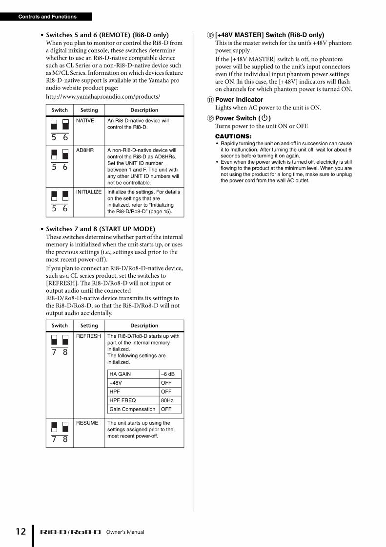
• Switches 5 and 6 (REMOTE) (Ri8-D only)When you plan to monitor or control the Ri8-D from a digital mixing console, these switches determine whether to use an Ri8-D-native compatible device such as CL Series or a non-Ri8-D-native device such as M7CL Series. Information on which devices feature Ri8-D-native support is available at the Yamaha pro audio website product page:http://www.yamahaproaudio.com/products/
• Switches 7 and 8 (START UP MODE)These switches determine whether part of the internal memory is initialized when the unit starts up, or uses the previous settings (i.e., settings used prior to the most recent power-off).If you plan to connect an Ri8-D/Ro8-D-native device, such as a CL series product, set the switches to [REFRESH]. The Ri8-D/Ro8-D will not input or output audio until the connected Ri8-D/Ro8-D-native device transmits its settings to the Ri8-D/Ro8-D, so that the Ri8-D/Ro8-D will not output audio accidentally.
0 [+48V MASTER] Switch (Ri8-D only)This is the master switch for the unit’s +48V phantom power supply.If the [+48V MASTER] switch is off, no phantom power will be supplied to the unit’s input connectors even if the individual input phantom power settings are ON. In this case, the [+48V] indicators will flash on channels for which phantom power is turned ON.
APower IndicatorLights when AC power to the unit is ON.
BPower Switch ( )Turns power to the unit ON or OFF.CAUTIONS:• Rapidly turning the unit on and off in succession can cause
it to malfunction. After turning the unit off, wait for about 6 seconds before turning it on again.
• Even when the power switch is turned off, electricity is still flowing to the product at the minimum level. When you are not using the product for a long time, make sure to unplug the power cord from the wall AC outlet.
Switch Setting Description
NATIVE An Ri8-D-native device will control the Ri8-D.
AD8HR A non-Ri8-D-native device will control the Ri8-D as AD8HRs.Set the UNIT ID number between 1 and F. The unit with any other UNIT ID numbers will not be controllable.
INITIALIZE Initialize the settings. For details on the settings that are initialized, refer to “Initializing the Ri8-D/Ro8-D” (page 15).
Switch Setting Description
REFRESH The Ri8-D/Ro8-D starts up with part of the internal memory initialized.The following settings are initialized.
RESUME The unit starts up using the settings assigned prior to the most recent power-off.
5 6
5 6
5 6
7 8
HA GAIN –6 dB
+48V OFF
HPF OFF
HPF FREQ 80Hz
Gain Compensation OFF
7 8
Owner’s Manual
Engl
ish
Rear Panel
Rear Panel
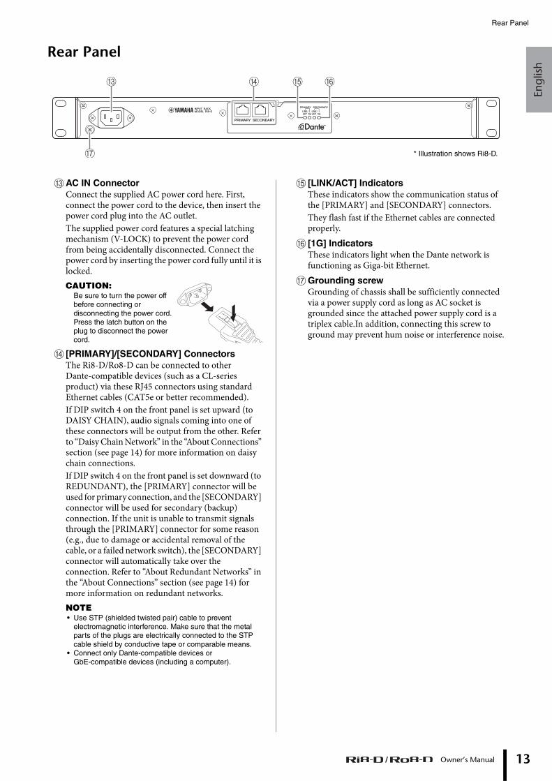
CAC IN ConnectorConnect the supplied AC power cord here. First, connect the power cord to the device, then insert the power cord plug into the AC outlet.The supplied power cord features a special latching mechanism (V-LOCK) to prevent the power cord from being accidentally disconnected. Connect the power cord by inserting the power cord fully until it is locked.CAUTION:
Be sure to turn the power off before connecting or disconnecting the power cord.Press the latch button on the plug to disconnect the power cord.
D [PRIMARY]/[SECONDARY] ConnectorsThe Ri8-D/Ro8-D can be connected to other Dante-compatible devices (such as a CL-series product) via these RJ45 connectors using standard Ethernet cables (CAT5e or better recommended).If DIP switch 4 on the front panel is set upward (to DAISY CHAIN), audio signals coming into one of these connectors will be output from the other. Refer to “Daisy Chain Network” in the “About Connections” section (see page 14) for more information on daisy chain connections.If DIP switch 4 on the front panel is set downward (to REDUNDANT), the [PRIMARY] connector will be used for primary connection, and the [SECONDARY] connector will be used for secondary (backup) connection. If the unit is unable to transmit signals through the [PRIMARY] connector for some reason (e.g., due to damage or accidental removal of the cable, or a failed network switch), the [SECONDARY] connector will automatically take over the connection. Refer to “About Redundant Networks” in the “About Connections” section (see page 14) for more information on redundant networks.NOTE• Use STP (shielded twisted pair) cable to prevent
electromagnetic interference. Make sure that the metal parts of the plugs are electrically connected to the STP cable shield by conductive tape or comparable means.
• Connect only Dante-compatible devices or GbE-compatible devices (including a computer).
E [LINK/ACT] IndicatorsThese indicators show the communication status of the [PRIMARY] and [SECONDARY] connectors.They flash fast if the Ethernet cables are connected properly.
F [1G] IndicatorsThese indicators light when the Dante network is functioning as Giga-bit Ethernet.
GGrounding screwGrounding of chassis shall be sufficiently connected via a power supply cord as long as AC socket is grounded since the attached power supply cord is a triplex cable.In addition, connecting this screw to ground may prevent hum noise or interference noise.
C E FD
G * Illustration shows Ri8-D.
Owner’s Manual 13
About Connections
14
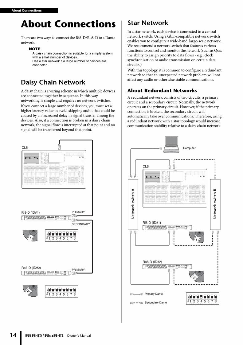
About ConnectionsThere are two ways to connect the Ri8-D/Ro8-D to a Dante network.
NOTEA daisy chain connection is suitable for a simple system with a small number of devices. Use a star network if a large number of devices are connected.
Daisy Chain NetworkA daisy chain is a wiring scheme in which multiple devices are connected together in sequence. In this way, networking is simple and requires no network switches. If you connect a large number of devices, you must set a higher latency value to avoid skipping audio that could be caused by an increased delay in signal transfer among the devices. Also, if a connection is broken in a daisy chain network, the signal flow is interrupted at that point and no signal will be transferred beyond that point.
Star NetworkIn a star network, each device is connected to a central network switch. Using a GbE-compatible network switch enables you to configure a wide-band, large-scale network. We recommend a network switch that features various functions to control and monitor the network (such as Qos, the ability to assign priority to data flows - e.g., clock synchronization or audio transmission on certain data circuits.)With this topology, it is common to configure a redundant network so that an unexpected network problem will not affect any audio or otherwise stable communications.
About Redundant NetworksA redundant network consists of two circuits, a primary circuit and a secondary circuit. Normally, the network operates on the primary circuit. However, if the primary connection is broken, the secondary circuit will automatically take over communications. Therefore, using a redundant network with a star topology would increase communication stability relative to a daisy chain network.
01234 EF
01234 EF
1 2 3 4 5 6 7 8ON
1 2 3 4 5 6 7 8ON
CL5
Ri8-D (ID#1)
Ro8-D (ID#2)
SECONDARY
PRIMARY
PRIMARY
1 1 2 3 4 5 6 7 8ON
1 1 2 3 4 5 6 7 8ON
Ri8-D (ID#1)
Ro8-D (ID#2)
1 2 3 4 5 6 7 8ON
1 1 2 3 4 5 6 7 8ON
1 1 2 3 4 5 6 7 8ON
CL5
01234 EF
01234 EF
Computer
Net
wo
rk s
wit
ch A
Net
wo
rk s
wit
ch B
Primary Dante
Secondary Dante
Owner’s Manual
Engl
ish
About Dante Controller
About Dante ControllerDante Controller is a software application that allows configuration and audio routing of Dante networks. Use this application if you plan to connect or set up Dante-enabled devices that do not feature Ri8-D/Ro8-D-native support. Please download the latest Dante Controller from the following website.Please note that Dante Controller Version 3.2.1 or later supports Ri8-D/Ro8-D.
http://www.yamahaproaudio.com/
To run Dante Controller, a computer must feature a GbE-compatible Ethernet connector.
Refer to the Dante Controller owner’s manual for details on Dante Controller.
In Dante Controller, make the following basic settings:• [Network View] → [Routing] → I/O patching • [Network View] → [Clock Status] → Word clock master
setting• [Device View] → [Config] → Sampling rate setting
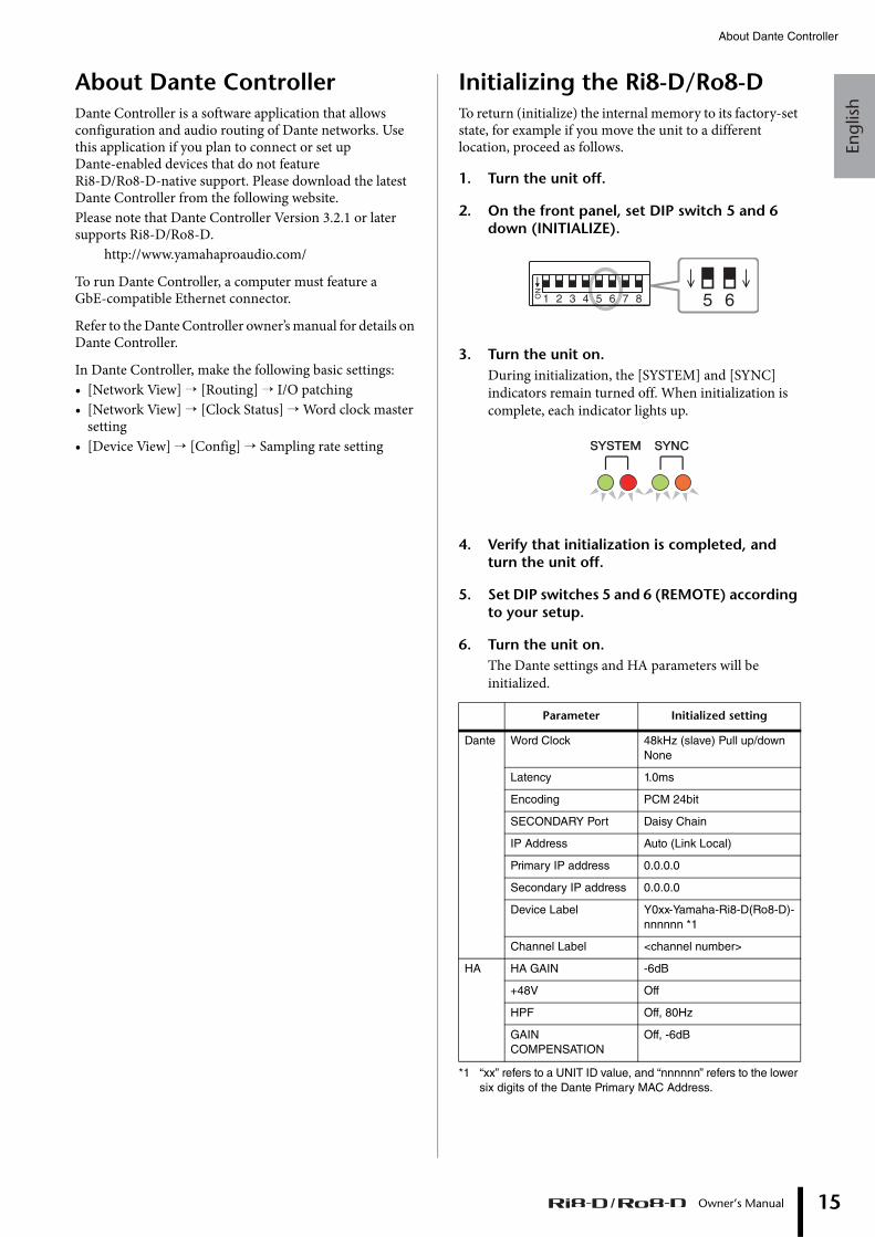
Initializing the Ri8-D/Ro8-DTo return (initialize) the internal memory to its factory-set state, for example if you move the unit to a different location, proceed as follows.
1. Turn the unit off.
2. On the front panel, set DIP switch 5 and 6 down (INITIALIZE).
3. Turn the unit on.During initialization, the [SYSTEM] and [SYNC] indicators remain turned off. When initialization is complete, each indicator lights up.
4. Verify that initialization is completed, and turn the unit off.
5. Set DIP switches 5 and 6 (REMOTE) according to your setup.
6. Turn the unit on.The Dante settings and HA parameters will be initialized.
*1 “xx” refers to a UNIT ID value, and “nnnnnn” refers to the lower six digits of the Dante Primary MAC Address.
Parameter Initialized setting
Dante Word Clock 48kHz (slave) Pull up/down None
Latency 1.0ms
Encoding PCM 24bit
SECONDARY Port Daisy Chain
IP Address Auto (Link Local)
Primary IP address 0.0.0.0
Secondary IP address 0.0.0.0
Device Label Y0xx-Yamaha-Ri8-D(Ro8-D)-nnnnnn *1
Channel Label <channel number>
HA HA GAIN -6dB
+48V Off
HPF Off, 80Hz
GAIN COMPENSATION
Off, -6dB
5 6ON
1 2 3 4 5 6 7 8
Owner’s Manual 15
Head Amp Control
Owner’s Manual16
Head Amp ControlThe Ri8-D head amplifiers can be remotely controlled from a host device, such as a compatible Yamaha digital mixing console.
Control from an Ri8-D-native DeviceThe Ri8-D head amplifiers can be controlled remotely from an Ri8-D-native digital mixing console, such as a CL series product.The connected Ri8-D-native device displays the model name and UNIT ID number of the corresponding Ri8-D unit to be controlled.If you plan to connect a device that features Ri8-D-native support to monitor and control the head amplifiers, refer to the owner’s manual for the corresponding device.
Control from a Device That Does Not Feature Ri8-D-Native SupportThis section explains how to configure the Ri8-D settings that are required to control the Ri8-D as AD8HR units from a device that does not feature Ri8-D-native support.For more information, please refer to the “Dante-MY 16-AUD & R Series HA Remote Control Guide” that is downloadable from the website listed below.
http://www.yamahaproaudio.com/NOTE
The following Yamaha non-Ri8-D-native devices enable you to control the Ri8-D as AD8HRs. Insert the Dante-MY16-AUD card which is a firmware controllable as AD8HR into the Mini-YGDAI slot for connection.
M7CL, LS9, DM1000, DM2000, PM5D/DSP5D, DME64N/24N
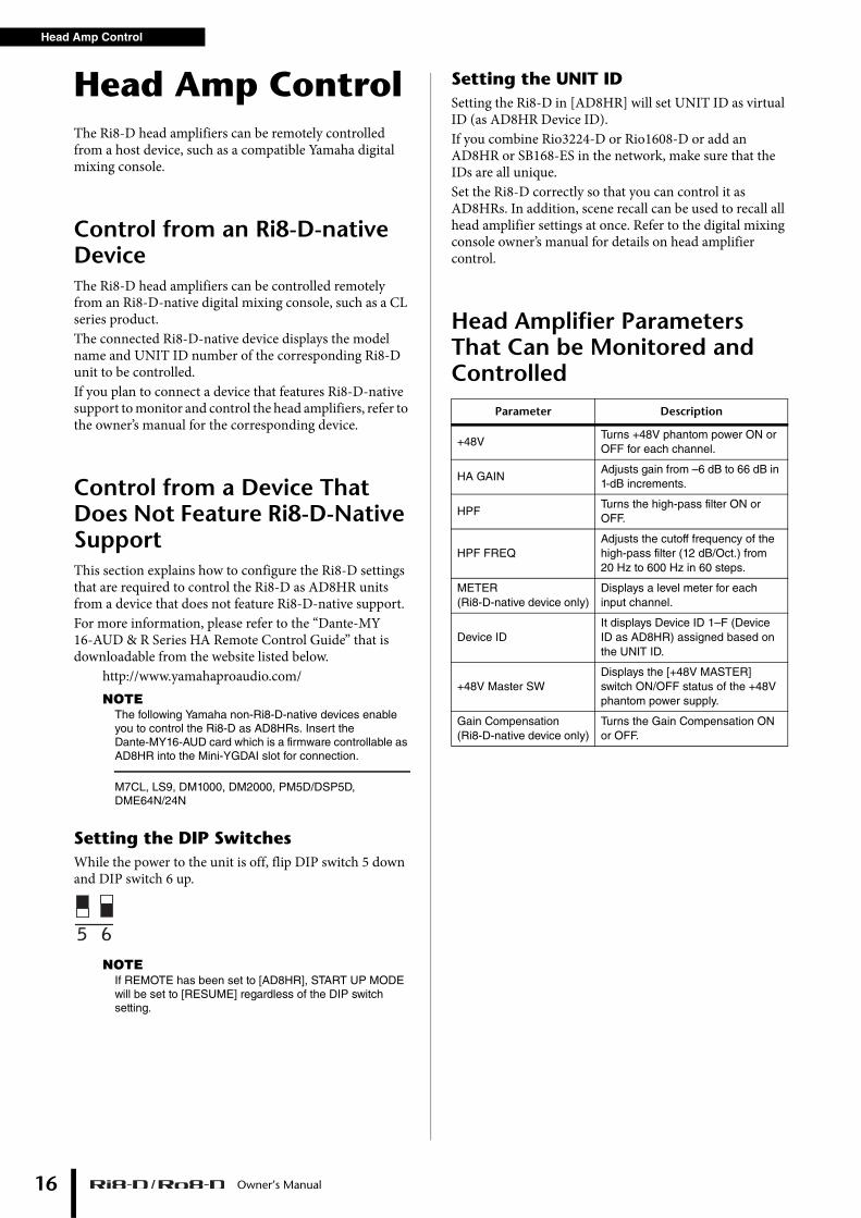
Setting the DIP SwitchesWhile the power to the unit is off, flip DIP switch 5 down and DIP switch 6 up.
NOTEIf REMOTE has been set to [AD8HR], START UP MODE will be set to [RESUME] regardless of the DIP switch setting.
Setting the UNIT IDSetting the Ri8-D in [AD8HR] will set UNIT ID as virtual ID (as AD8HR Device ID).If you combine Rio3224-D or Rio1608-D or add an AD8HR or SB168-ES in the network, make sure that the IDs are all unique. Set the Ri8-D correctly so that you can control it as AD8HRs. In addition, scene recall can be used to recall all head amplifier settings at once. Refer to the digital mixing console owner’s manual for details on head amplifier control.
Head Amplifier Parameters That Can be Monitored and Controlled
5 6
Parameter Description
+48VTurns +48V phantom power ON or OFF for each channel.
HA GAINAdjusts gain from –6 dB to 66 dB in 1-dB increments.
HPFTurns the high-pass filter ON or OFF.
HPF FREQAdjusts the cutoff frequency of the high-pass filter (12 dB/Oct.) from 20 Hz to 600 Hz in 60 steps.
METER (Ri8-D-native device only)
Displays a level meter for each input channel.
Device IDIt displays Device ID 1–F (Device ID as AD8HR) assigned based on the UNIT ID.
+48V Master SWDisplays the [+48V MASTER] switch ON/OFF status of the +48V phantom power supply.
Gain Compensation (Ri8-D-native device only)
Turns the Gain Compensation ON or OFF.
Engl
ish
Troubleshooting
Troubleshooting
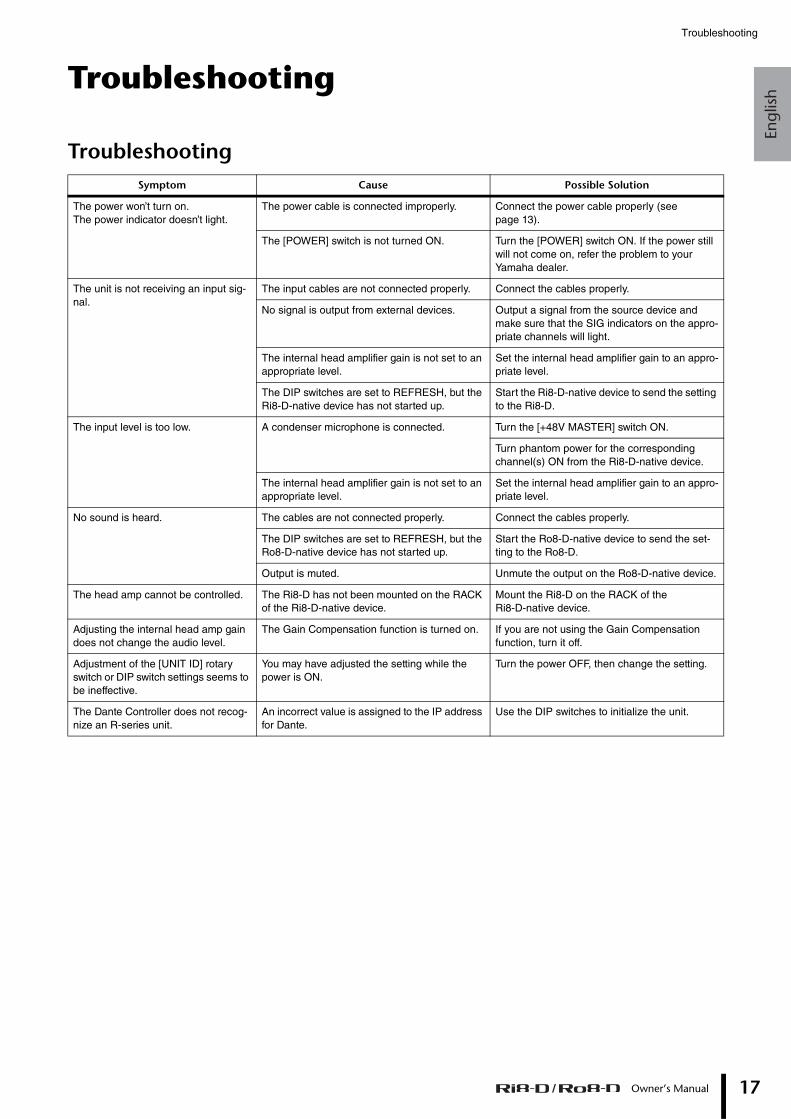
TroubleshootingSymptom Cause Possible Solution
The power won’t turn on. The power indicator doesn’t light.
The power cable is connected improperly. Connect the power cable properly (see page 13).
The [POWER] switch is not turned ON. Turn the [POWER] switch ON. If the power still will not come on, refer the problem to your Yamaha dealer.
The unit is not receiving an input sig-nal.
The input cables are not connected properly. Connect the cables properly.
No signal is output from external devices. Output a signal from the source device and make sure that the SIG indicators on the appro-priate channels will light.
The internal head amplifier gain is not set to an appropriate level.
Set the internal head amplifier gain to an appro-priate level.
The DIP switches are set to REFRESH, but the Ri8-D-native device has not started up.
Start the Ri8-D-native device to send the setting to the Ri8-D.
The input level is too low. A condenser microphone is connected. Turn the [+48V MASTER] switch ON.
Turn phantom power for the corresponding channel(s) ON from the Ri8-D-native device.
The internal head amplifier gain is not set to an appropriate level.
Set the internal head amplifier gain to an appro-priate level.
No sound is heard. The cables are not connected properly. Connect the cables properly.
The DIP switches are set to REFRESH, but the Ro8-D-native device has not started up.
Start the Ro8-D-native device to send the set-ting to the Ro8-D.
Output is muted. Unmute the output on the Ro8-D-native device.
The head amp cannot be controlled. The Ri8-D has not been mounted on the RACK of the Ri8-D-native device.
Mount the Ri8-D on the RACK of the Ri8-D-native device.
Adjusting the internal head amp gain does not change the audio level.
The Gain Compensation function is turned on. If you are not using the Gain Compensation function, turn it off.
Adjustment of the [UNIT ID] rotary switch or DIP switch settings seems to be ineffective.
You may have adjusted the setting while the power is ON.
Turn the power OFF, then change the setting.
The Dante Controller does not recog-nize an R-series unit.
An incorrect value is assigned to the IP address for Dante.
Use the DIP switches to initialize the unit.
Owner’s Manual 17
Troubleshooting
18
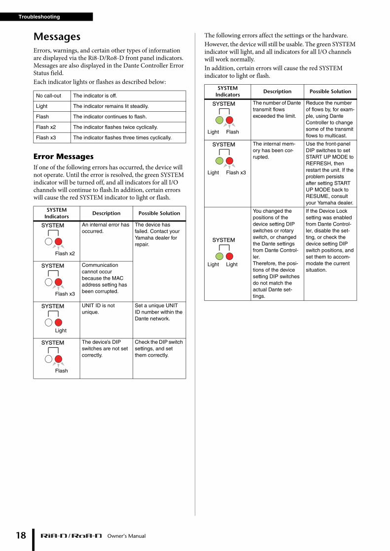
MessagesErrors, warnings, and certain other types of information are displayed via the Ri8-D/Ro8-D front panel indicators. Messages are also displayed in the Dante Controller Error Status field.Each indicator lights or flashes as described below:
Error MessagesIf one of the following errors has occurred, the device will not operate. Until the error is resolved, the green SYSTEM indicator will be turned off, and all indicators for all I/O channels will continue to flash.In addition, certain errors will cause the red SYSTEM indicator to light or flash.
The following errors affect the settings or the hardware.However, the device will still be usable. The green SYSTEM indicator will light, and all indicators for all I/O channels will work normally.In addition, certain errors will cause the red SYSTEM indicator to light or flash.
No call-out The indicator is off.
Light The indicator remains lit steadily.
Flash The indicator continues to flash.
Flash x2 The indicator flashes twice cyclically.
Flash x3 The indicator flashes three times cyclically.
SYSTEM Indicators
Description Possible Solution
An internal error has occurred.
The device has failed. Contact your Yamaha dealer for repair.
Communication cannot occur because the MAC address setting has been corrupted.
UNIT ID is not unique.
Set a unique UNIT ID number within the Dante network.
The device’s DIP switches are not set correctly.
Check the DIP switch settings, and set them correctly.
Flash x2
Flash x3
Light
Flash
SYSTEM Indicators
Description Possible Solution
The number of Dante transmit flows exceeded the limit.
Reduce the number of flows by, for exam-ple, using Dante Controller to change some of the transmit flows to multicast.
The internal mem-ory has been cor-rupted.
Use the front-panel DIP switches to set START UP MODE to REFRESH, then restart the unit. If the problem persists after setting START UP MODE back to RESUME, consult your Yamaha dealer.
You changed the positions of the device setting DIP switches or rotary switch, or changed the Dante settings from Dante Control-ler.Therefore, the posi-tions of the device setting DIP switches do not match the actual Dante set-tings.
If the Device Lock setting was enabled from Dante Control-ler, disable the set-ting, or check the device setting DIP switch positions, and set them to accom-modate the current situation.
FlashLight
Flash x3Light
LightLight
Owner’s Manual
Engl
ish
Messages
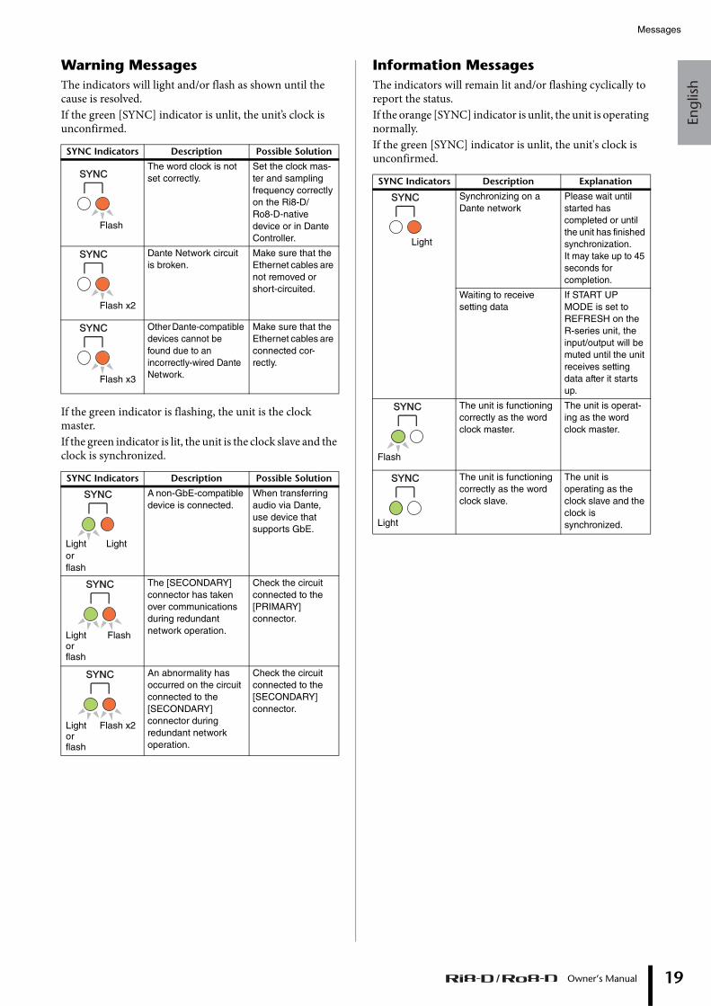
Warning MessagesThe indicators will light and/or flash as shown until the cause is resolved.If the green [SYNC] indicator is unlit, the unit’s clock is unconfirmed.
If the green indicator is flashing, the unit is the clock master.If the green indicator is lit, the unit is the clock slave and the clock is synchronized.
Information MessagesThe indicators will remain lit and/or flashing cyclically to report the status.If the orange [SYNC] indicator is unlit, the unit is operating normally.If the green [SYNC] indicator is unlit, the unit's clock is unconfirmed.SYNC Indicators Description Possible Solution
The word clock is not set correctly.
Set the clock mas-ter and sampling frequency correctly on the Ri8-D/ Ro8-D-native device or in Dante Controller.
Dante Network circuit is broken.
Make sure that the Ethernet cables are not removed or short-circuited.
Other Dante-compatible devices cannot be found due to an incorrectly-wired Dante Network.
Make sure that the Ethernet cables are connected cor-rectly.
SYNC Indicators Description Possible Solution
A non-GbE-compatible device is connected.
When transferring audio via Dante, use device that supports GbE.
The [SECONDARY] connector has taken over communications during redundant network operation.
Check the circuit connected to the [PRIMARY] connector.
An abnormality has occurred on the circuit connected to the [SECONDARY] connector during redundant network operation.
Check the circuit connected to the [SECONDARY] connector.
Flash
Flash x2
Flash x3
LightLight or flash
FlashLight or flash
Flash x2Light or flash
SYNC Indicators Description Explanation
Synchronizing on a Dante network
Please wait until started has completed or until the unit has finished synchronization. It may take up to 45 seconds for completion.
Waiting to receive setting data
If START UP MODE is set to REFRESH on the R-series unit, the input/output will be muted until the unit receives setting data after it starts up.
The unit is functioning correctly as the word clock master.
The unit is operat-ing as the word clock master.
The unit is functioning correctly as the word clock slave.
The unit is operating as the clock slave and the clock is synchronized.
Light
Flash
Light
Owner’s Manual 19

20
MEMO
Owner’s Manual
Engl
ish
Deu
tsch
Fran
çais
Esp
añol
Port
uguê
sIt
alia
noРусски
й日本語
Specifications
Specifications
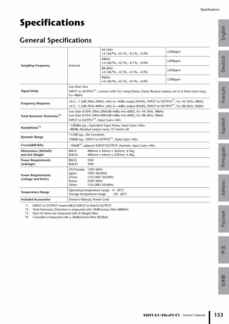
General Specifications
Sampling Frequency External
44.1kHz+4.1667%, +0.1%, –0.1%, –4.0%
±200ppm
48kHz+4.1667%, +0.1%, –0.1%, –4.0%
±200ppm
88.2kHz+4.1667%, +0.1%, –0.1%, –4.0%
±200ppm
96kHz+4.1667%, +0.1%, –0.1%, –4.0%
±200ppm
Signal DelayLess than 3ms
INPUT to OUTPUT*1, connect with CL5 using Dante, Dante Receive Latency set to 0.25ms (one way), Fs= 48kHz
*1. INPUT to OUTPUT means Ri8-D INPUT to Ro8-D OUTPUT
Frequency Response+0.5, –1.5dB 20Hz-20kHz, refer to +4dBu output @1kHz, INPUT to OUTPUT*1, Fs= 44.1kHz, 48kHz
+0.5, –1.5dB 20Hz-40kHz, refer to +4dBu output @1kHz, INPUT to OUTPUT*1, Fs= 88.2kHz, 96kHz
Total Harmonic Distortion*2
*2. Total Harmonic Distortion is measured with 18dB/octave filter @80kHz
Less than 0.05% 20Hz-20kHz@+4dBu into 600Ω, Fs= 44.1kHz, 48kHzLess than 0.05% 20Hz-40kHz@+4dBu into 600Ω, Fs= 88.2kHz, 96kHz
INPUT to OUTPUT*1, Input Gain= Min.
Hum&Noise*3
*3. Hum & Noise are measured with A-Weight filter.
–128dBu typ., Equivalent Input Noise, Input Gain= Max.–88dBu Residual output noise, ST master off.
Dynamic Range112dB typ., DA Converter,
108dB typ., INPUT to OUTPUT*1, Input Gain= Min.
Crosstalk@1kHz –100dB*4, adjacent INPUT/OUTPUT channels, Input Gain= Min.
*4. Crosstalk is measured with a 30dB/octave filter @22kHz
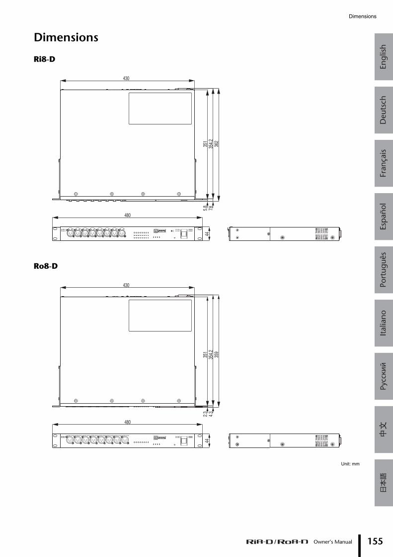
Dimensions (WxHxD)and Net Weight
Ri8-D: 480mm x 44mm x 362mm, 4.5kgRo8-D: 480mm x 44mm x 359mm, 4.4kg
Power Requirements(wattage)
Ri8-D: 35WRo8-D: 35W
Power Requirements(voltage and hertz)
US/Canada: 120V 60HzJapan: 100V 50/60HzChina: 110-240V 50/60HzKorea: 220V 60HzOther: 110-240V 50/60Hz
Temperature RangeOperating temperature range: 0 - 40°CStorage temperature range: –20 - 60°C
Included Accessories Owner’s Manual, Power Cord
Owner’s Manual 153
Specifications
154
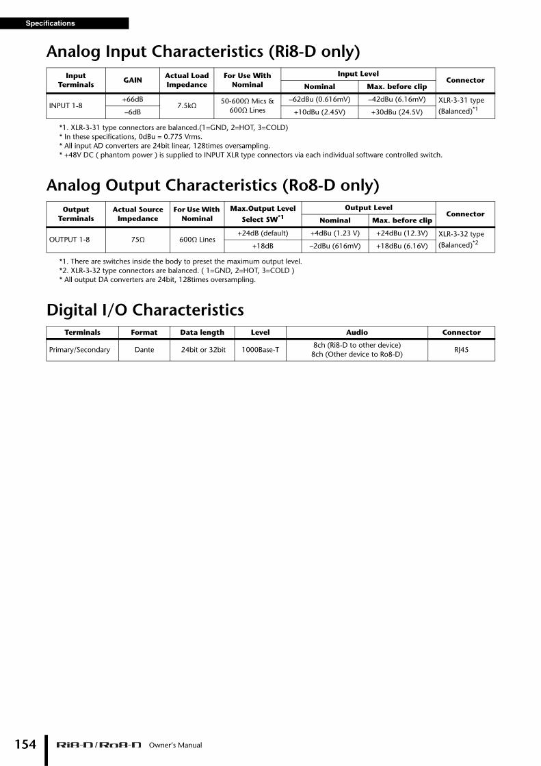
Analog Input Characteristics (Ri8-D only)
*1. XLR-3-31 type connectors are balanced.(1=GND, 2=HOT, 3=COLD)* In these specifications, 0dBu = 0.775 Vrms.* All input AD converters are 24bit linear, 128times oversampling.* +48V DC ( phantom power ) is supplied to INPUT XLR type connectors via each individual software controlled switch.
Analog Output Characteristics (Ro8-D only)
*1. There are switches inside the body to preset the maximum output level. *2. XLR-3-32 type connectors are balanced. ( 1=GND, 2=HOT, 3=COLD )* All output DA converters are 24bit, 128times oversampling.
Digital I/O Characteristics
Input Terminals
GAINActual Load Impedance
For Use With Nominal
Input LevelConnector
Nominal Max. before clip
INPUT 1-8+66dB
7.5kΩ50-600Ω Mics &
600Ω Lines
–62dBu (0.616mV) –42dBu (6.16mV) XLR-3-31 type
(Balanced)*1–6dB +10dBu (2.45V) +30dBu (24.5V)
Output Terminals
Actual Source Impedance
For Use With Nominal
Max.Output Level
Select SW*1
Output LevelConnector
Nominal Max. before clip
OUTPUT 1-8 75Ω 600Ω Lines+24dB (default) +4dBu (1.23 V) +24dBu (12.3V) XLR-3-32 type
(Balanced)*2+18dB –2dBu (616mV) +18dBu (6.16V)
Terminals Format Data length Level Audio Connector
Primary/Secondary Dante 24bit or 32bit 1000Base-T8ch (Ri8-D to other device)8ch (Other device to Ro8-D)
RJ45
Owner’s Manual
Engl
ish
Deu
tsch
Fran
çais
Esp
añol
Port
uguê
sIt
alia
noРусски
й日本語
Dimensions
Dimensions
Ri8-D
Ro8-D
Unit: mm
480
44
430
351
354.
236
27.85.
8
480
430
351
354.
235
9
2.3
4.3
44
Owner’s Manual 155


Published 12/2016 改版 IPHD-F0
© 2012 Yamaha CorporationManual Development Group
Printed in China
Yamaha Downloadshttp://download.yamaha.com/
Yamaha Pro Audio global websitehttp://www.yamahaproaudio.com/
ZX71430
1818 24000517700
http://www.yamaha.com.cn