Embed Size (px)
Citation preview
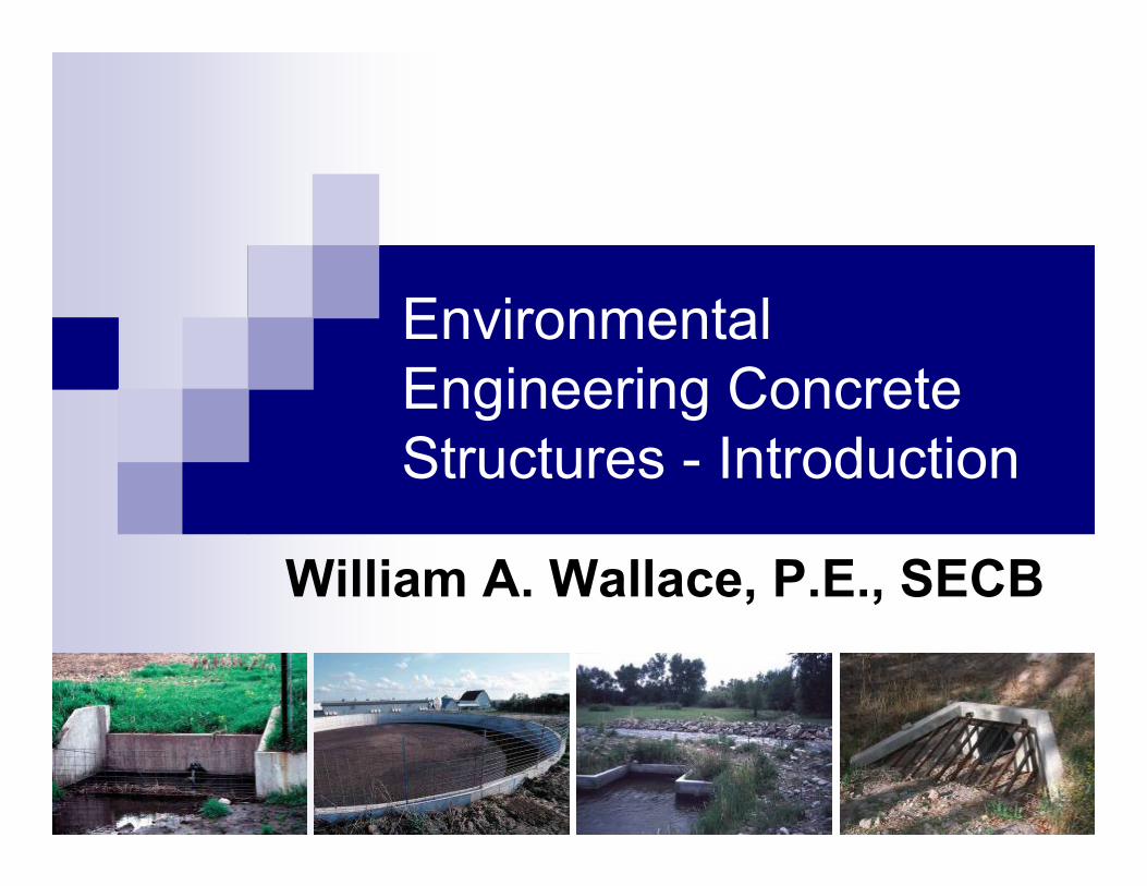
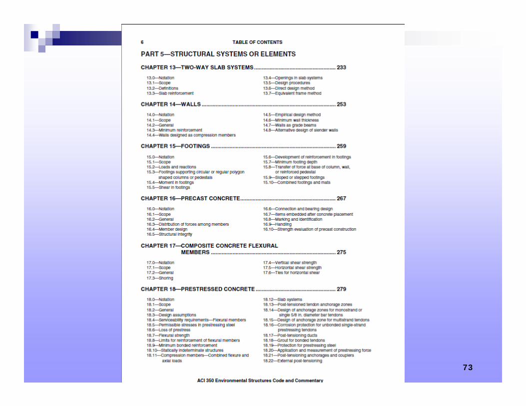
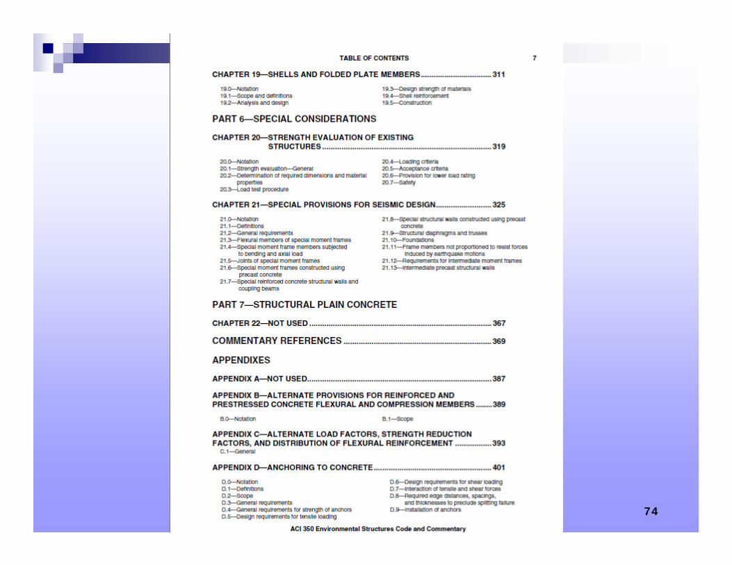
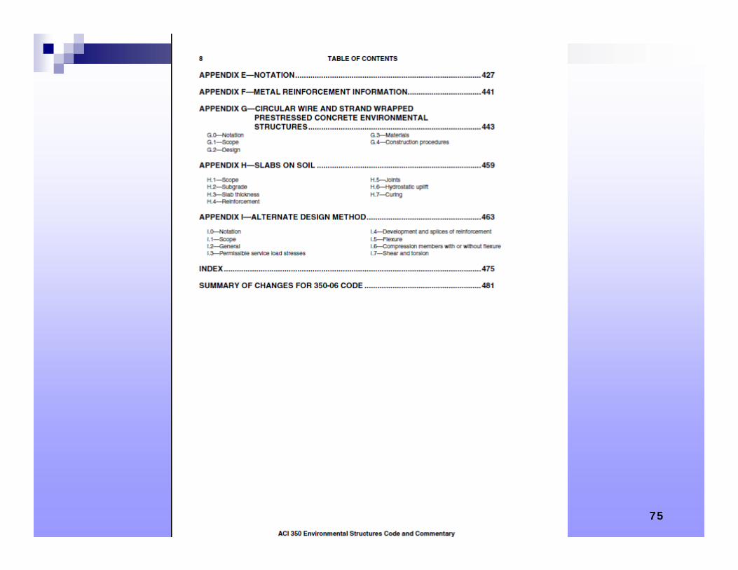
Environmental Engineering Concrete Structures - Introduction
William A. Wallace, P.E., SECB
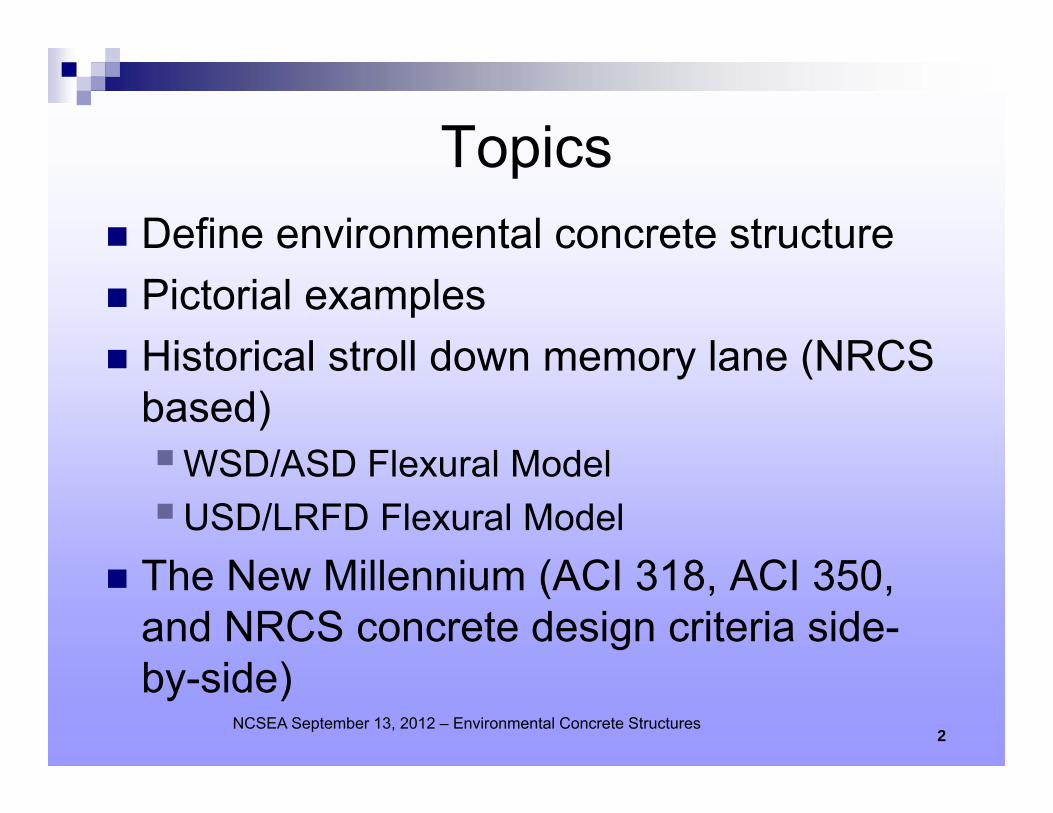
Topics Define environmental concrete structure Pictorial examples Historical stroll down memory lane (NRCS
based)WSD/ASD Flexural ModelUSD/LRFD Flexural Model
The New Millennium (ACI 318, ACI 350, and NRCS concrete design criteria side-by-side)
NCSEA September 13, 2012 – Environmental Concrete Structures2
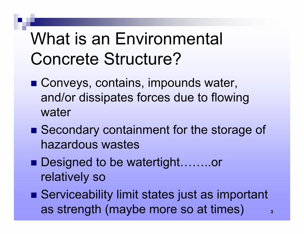
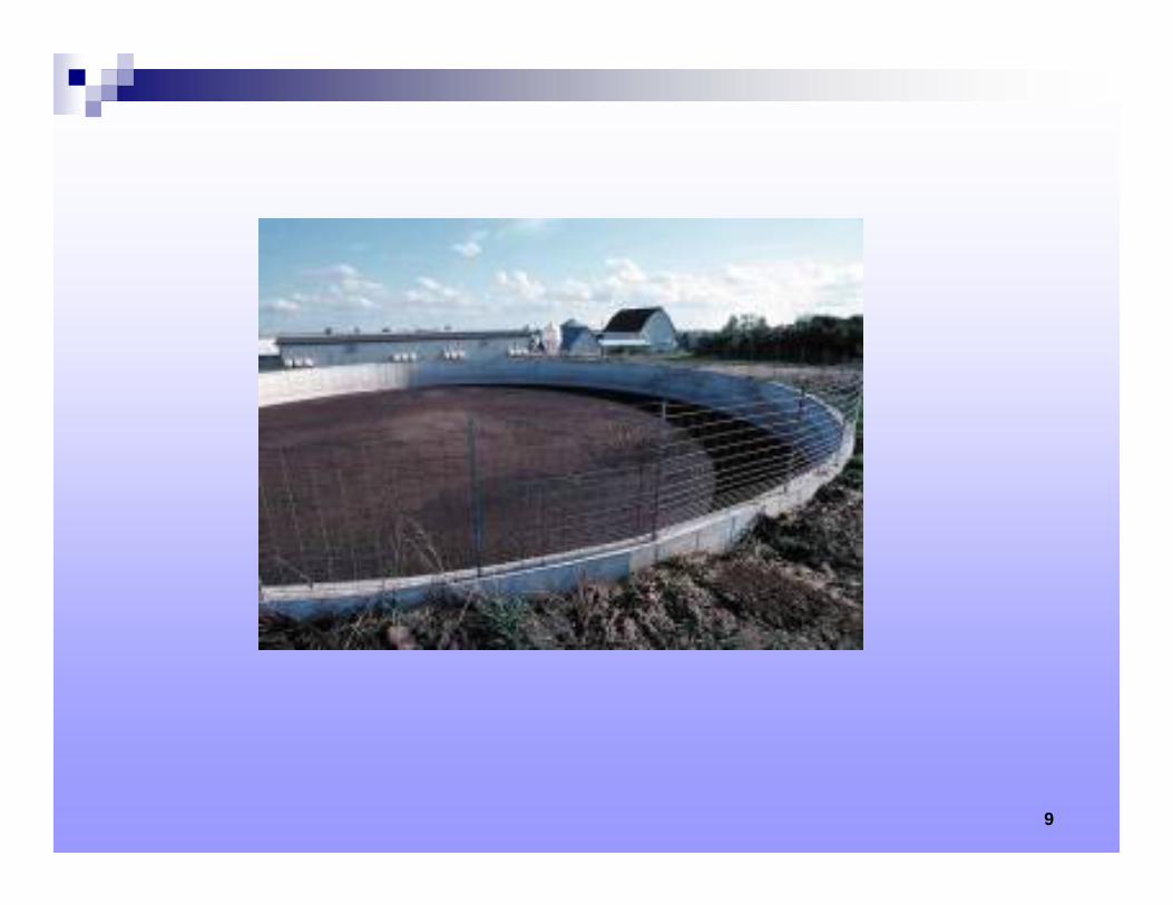
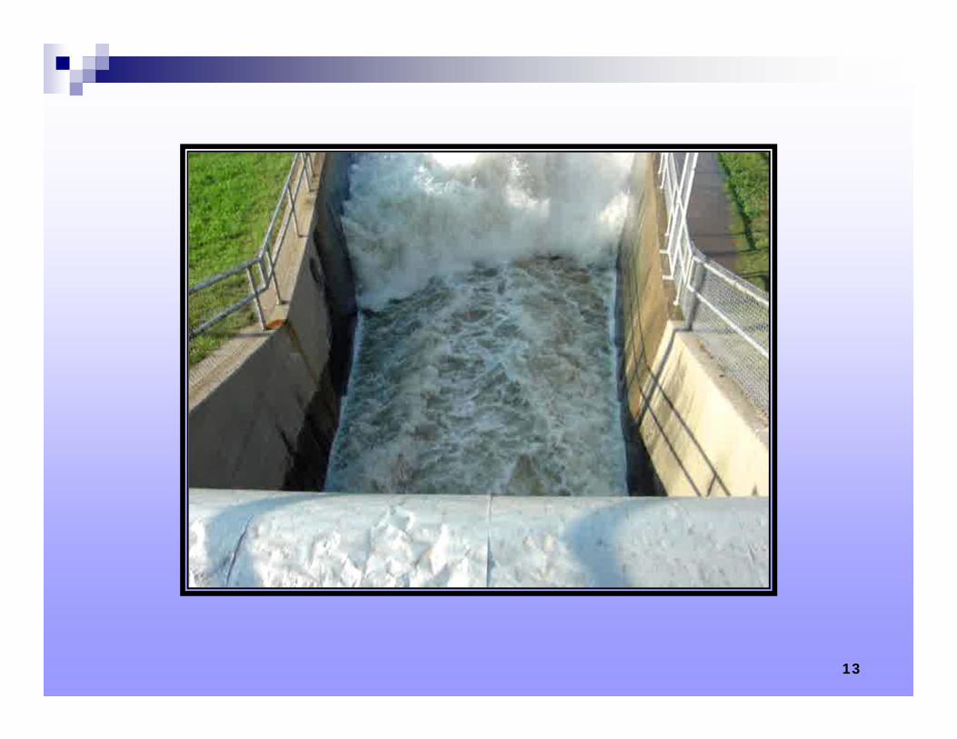
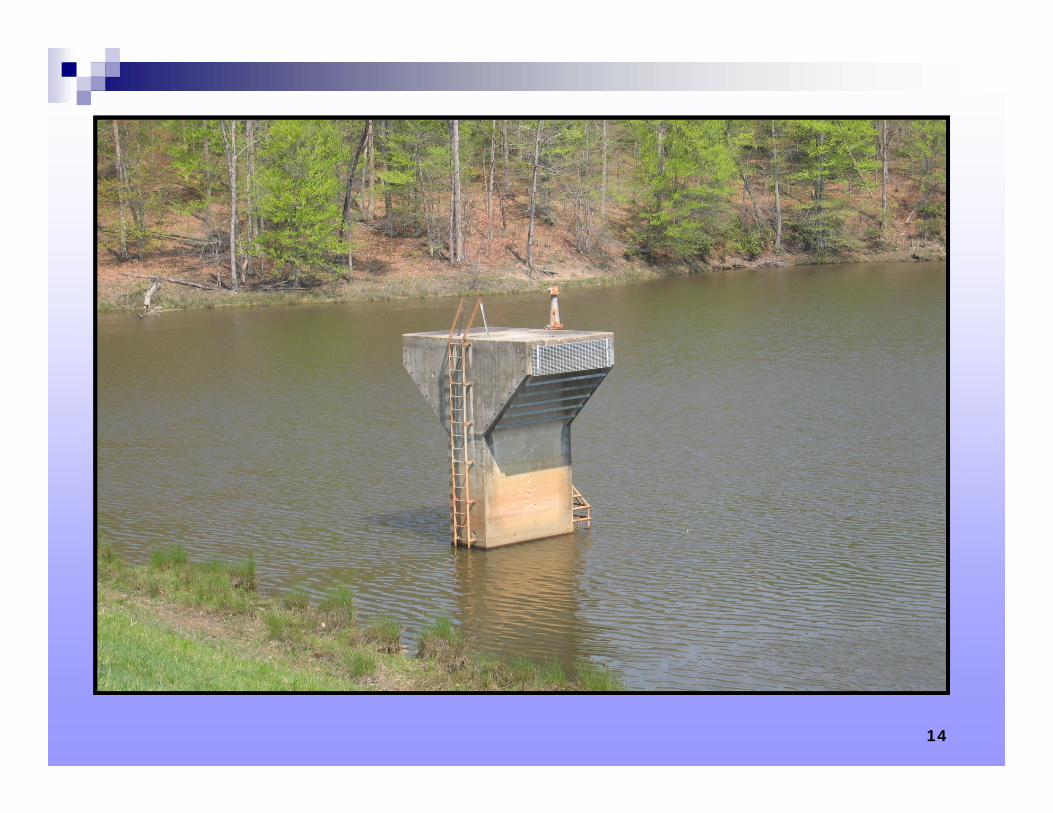
What is an Environmental Concrete Structure? Conveys, contains, impounds water,
and/or dissipates forces due to flowing water
Secondary containment for the storage of hazardous wastes
Designed to be watertight……..or relatively so
Serviceability limit states just as important as strength (maybe more so at times) 3
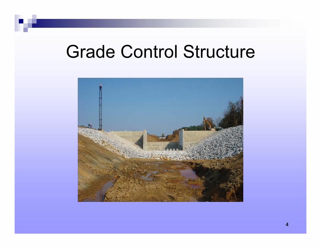
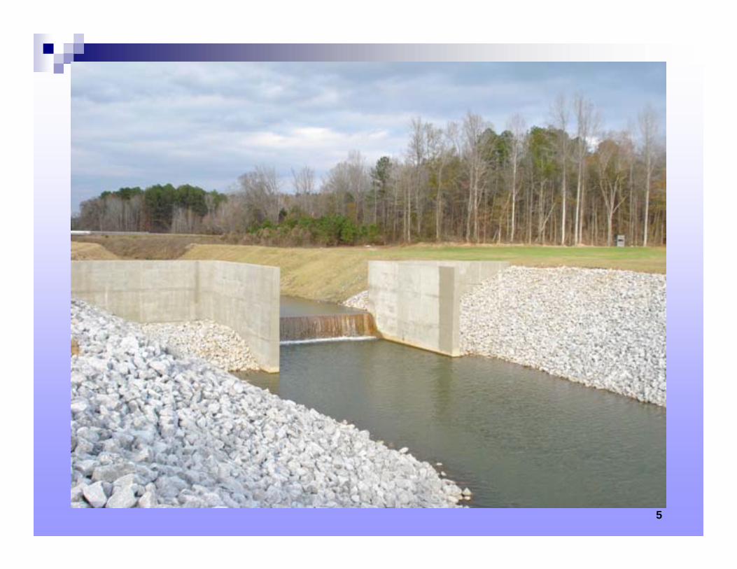
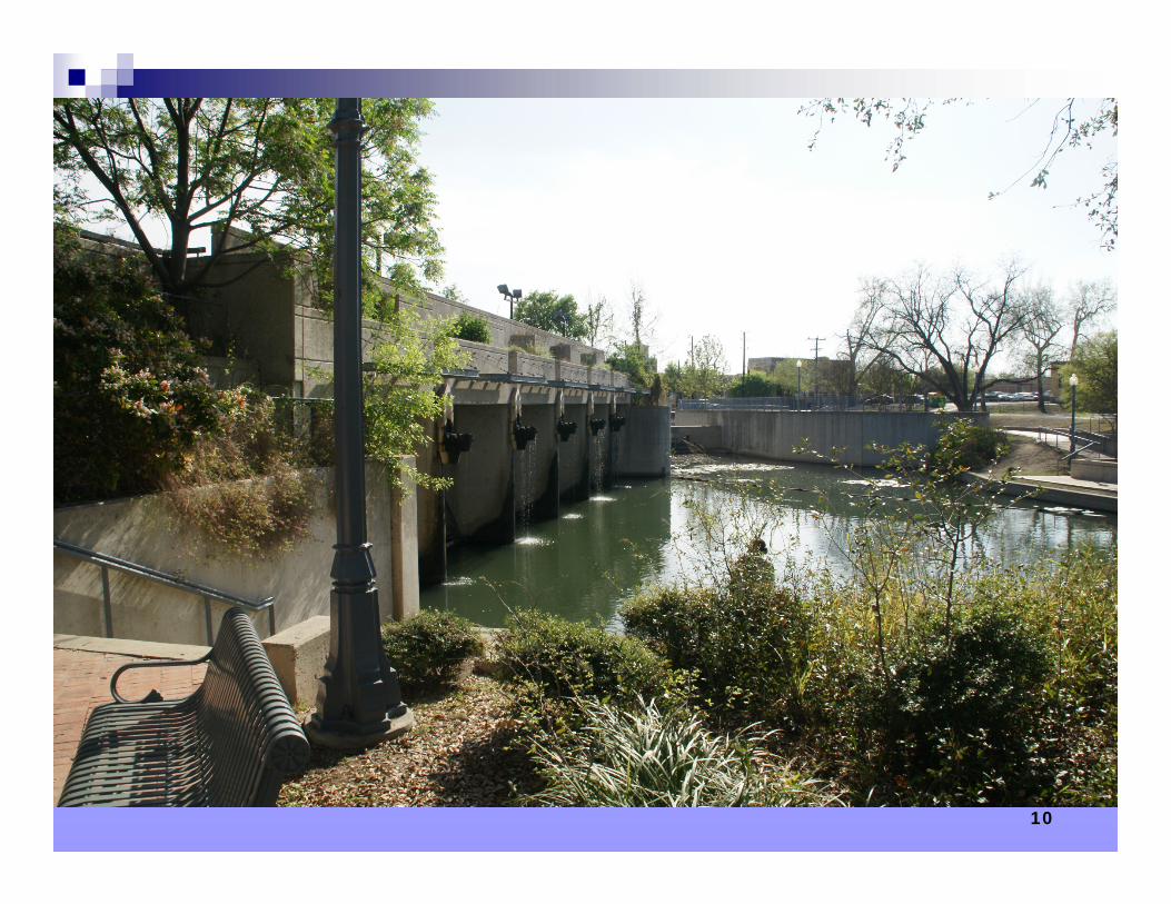
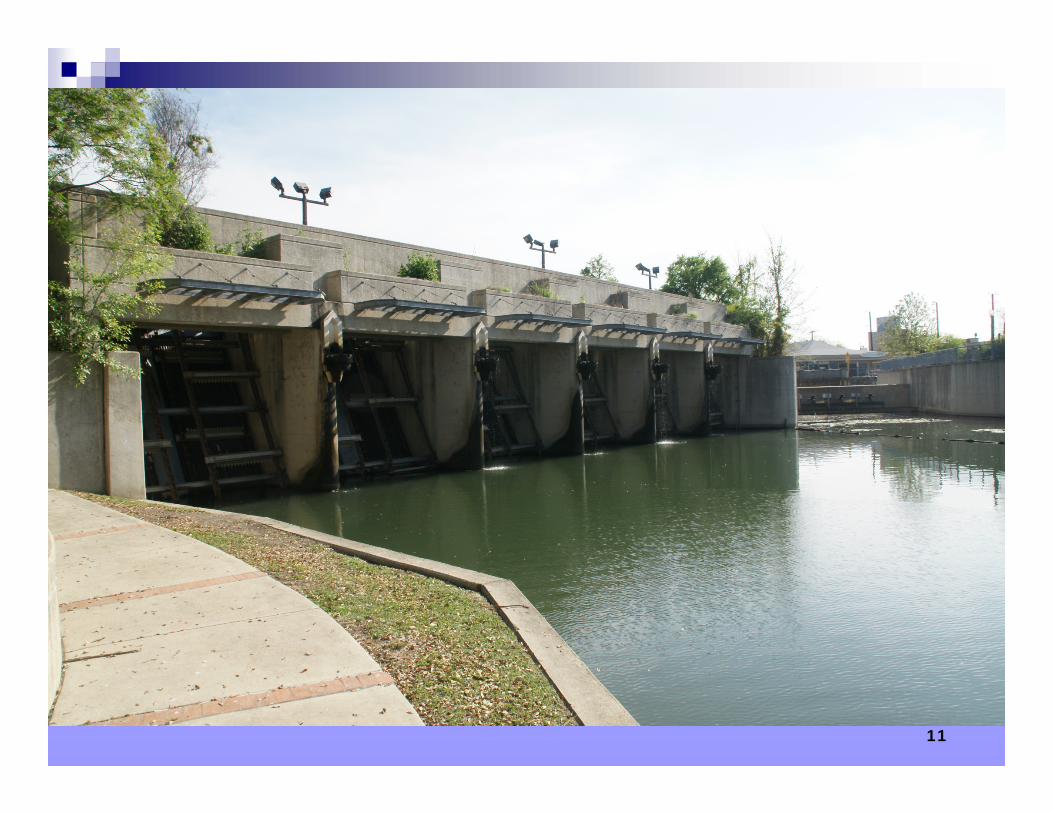
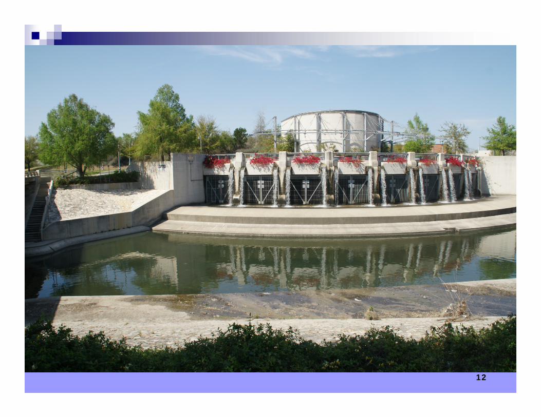
Grade Control Structure
4
5

6
7
Natural Resources Conservation Service 8
9
10
11
12
13
14
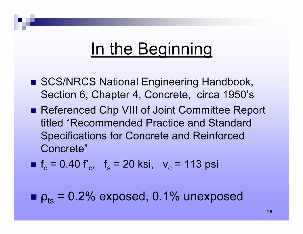
In the Beginning
SCS/NRCS National Engineering Handbook, Section 6, Chapter 4, Concrete, circa 1950’s
Referenced Chp VIII of Joint Committee Report titled “Recommended Practice and Standard Specifications for Concrete and Reinforced Concrete”
fc = 0.40 f’c, fs = 20 ksi, vc = 113 psi
ρts = 0.2% exposed, 0.1% unexposed15
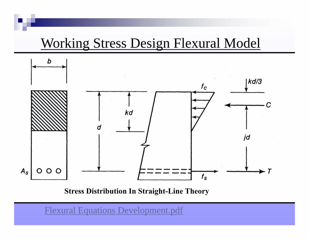
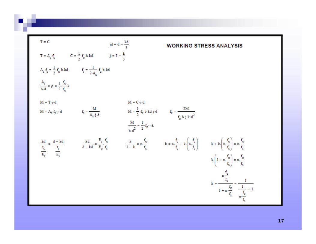
Stress Distribution In Straight-Line Theory
Flexural Equations Development.pdf
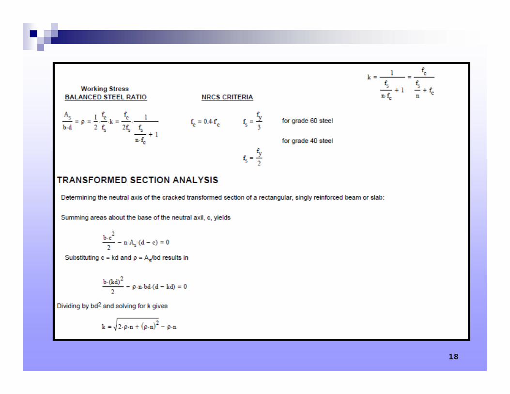
Working Stress Design Flexural Model
17
18
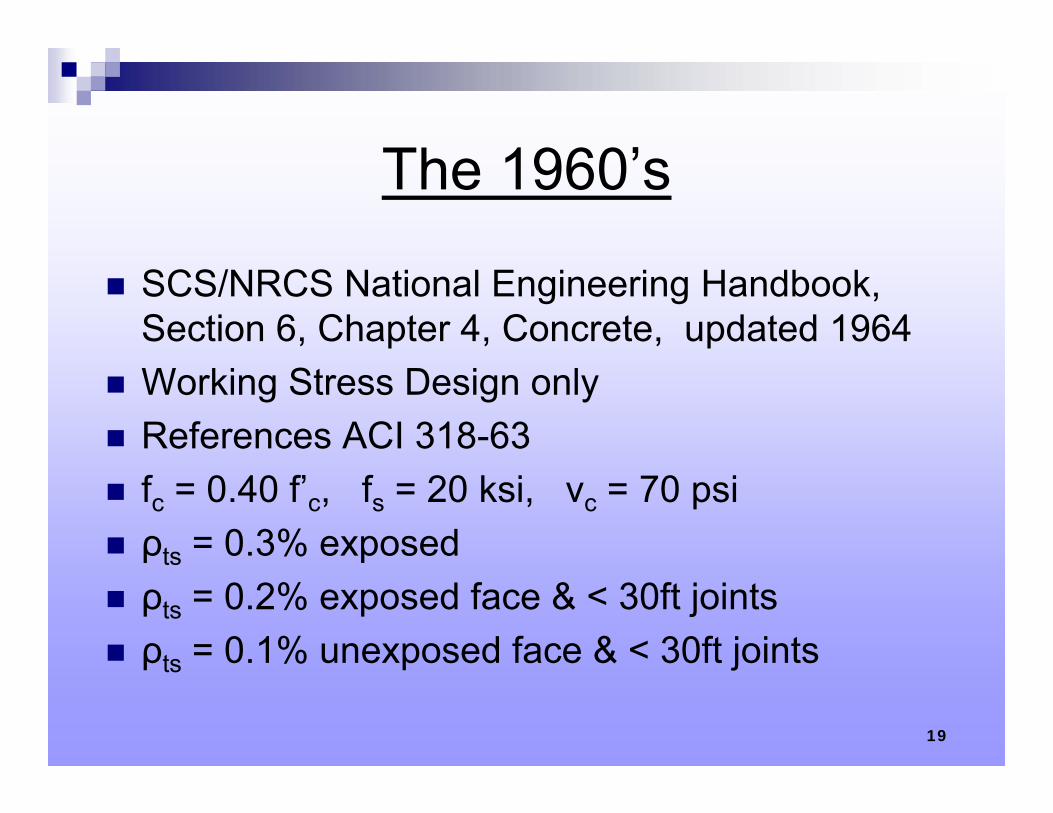
The 1960’s
SCS/NRCS National Engineering Handbook, Section 6, Chapter 4, Concrete, updated 1964
Working Stress Design only References ACI 318-63 fc = 0.40 f’c, fs = 20 ksi, vc = 70 psi ρts = 0.3% exposed ρts = 0.2% exposed face & < 30ft joints ρts = 0.1% unexposed face & < 30ft joints
19
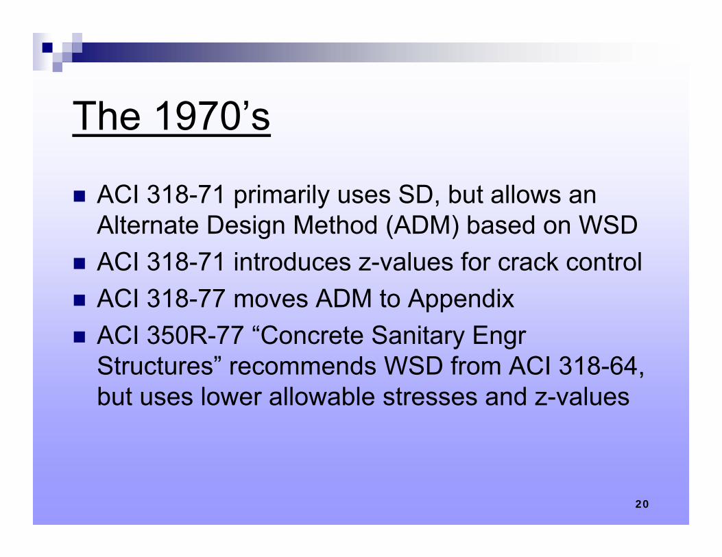
The 1970’s
ACI 318-71 primarily uses SD, but allows an Alternate Design Method (ADM) based on WSD
ACI 318-71 introduces z-values for crack control ACI 318-77 moves ADM to Appendix ACI 350R-77 “Concrete Sanitary Engr
Structures” recommends WSD from ACI 318-64, but uses lower allowable stresses and z-values
20
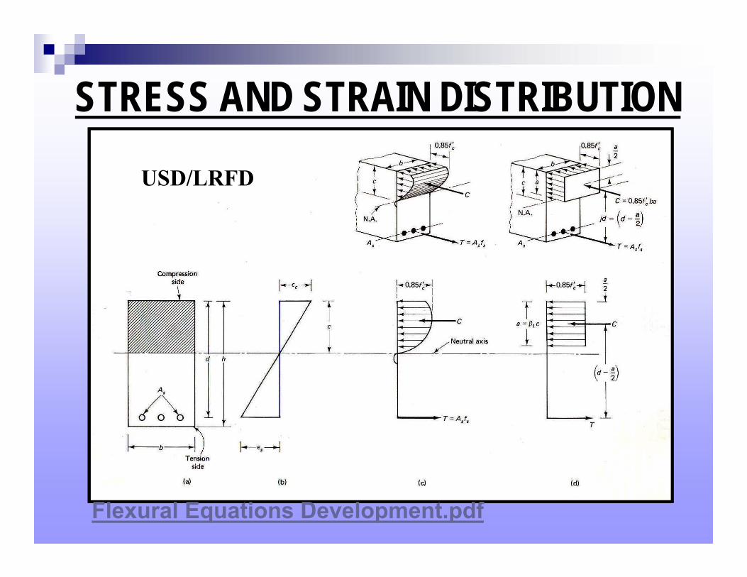
STRESS AND STRAIN DISTRIBUTION
Flexural Equations Development.pdf
USD/LRFD
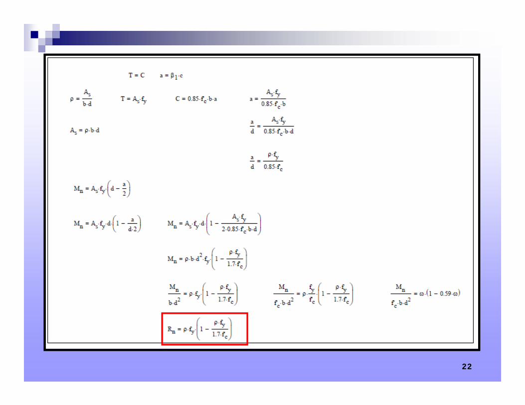
22
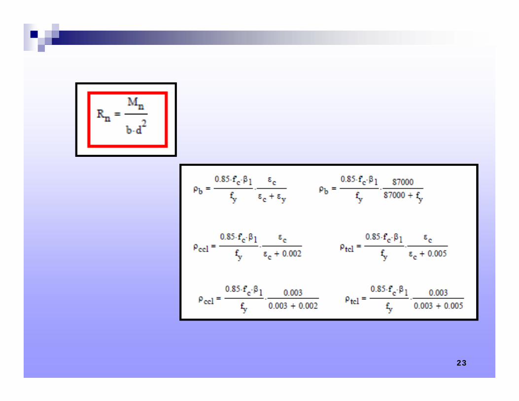
23
The 1980’s
SCS Technical Release No. 67 “Reinforced Concrete Strength Design” published 1980
Based on ACI 318-77 SD modified to produce similar design proportions as NEH 6 WSD
Modifications include higher load factors, limited design yield strengths, lower z-values, and lower maximum reinforcing steel ratio
SCS NEH-6 revised 1980 to include z-value criteria
24
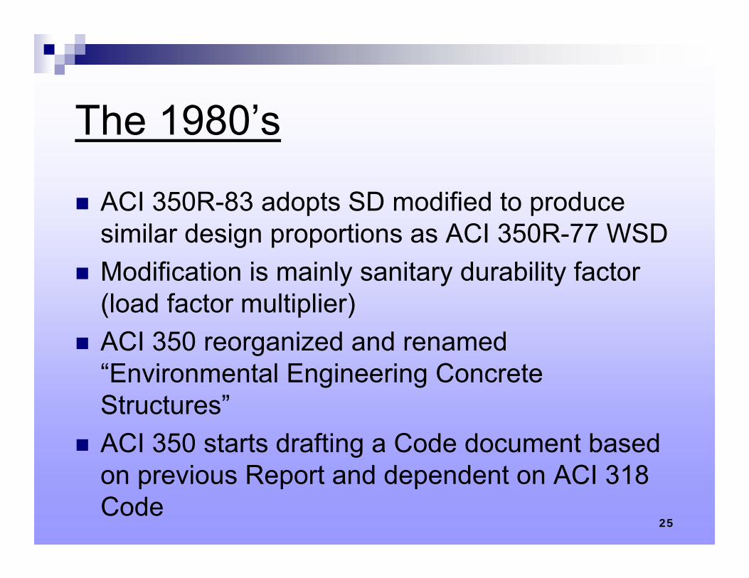
The 1980’s
ACI 350R-83 adopts SD modified to produce similar design proportions as ACI 350R-77 WSD
Modification is mainly sanitary durability factor (load factor multiplier)
ACI 350 reorganized and renamed “Environmental Engineering Concrete Structures”
ACI 350 starts drafting a Code document based on previous Report and dependent on ACI 318 Code
25
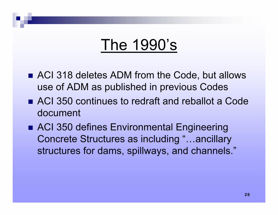
The 1990’s
ACI 318 deletes ADM from the Code, but allows use of ADM as published in previous Codes
ACI 350 continues to redraft and reballot a Code document
ACI 350 defines Environmental Engineering Concrete Structures as including “…ancillary structures for dams, spillways, and channels.”
26
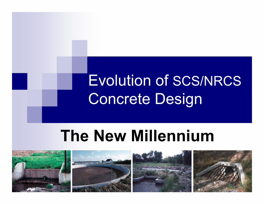
Evolution of SCS/NRCSConcrete Design
The New Millennium
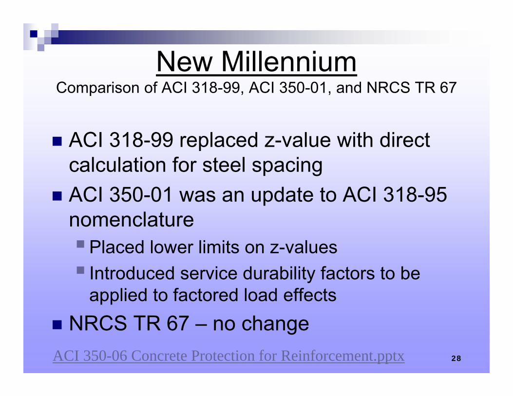
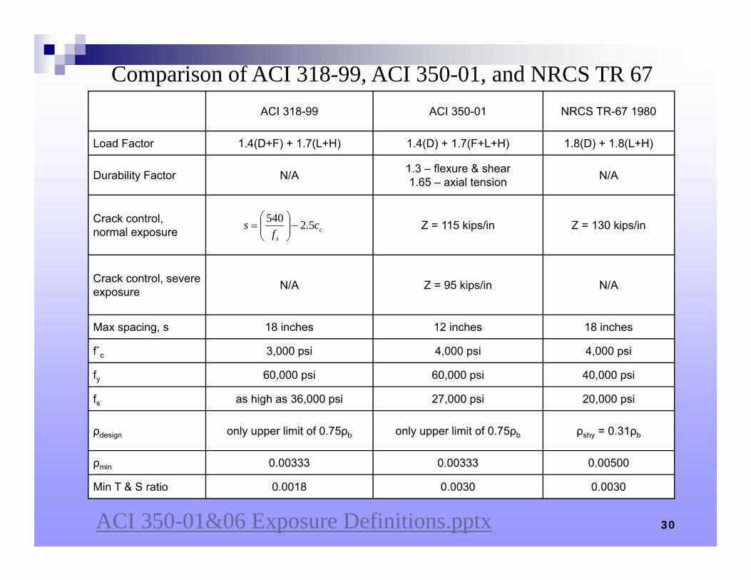
New MillenniumComparison of ACI 318-99, ACI 350-01, and NRCS TR 67
ACI 318-99 replaced z-value with direct calculation for steel spacing
ACI 350-01 was an update to ACI 318-95 nomenclaturePlaced lower limits on z-values Introduced service durability factors to be
applied to factored load effects NRCS TR 67 – no change
28ACI 350-06 Concrete Protection for Reinforcement.pptx
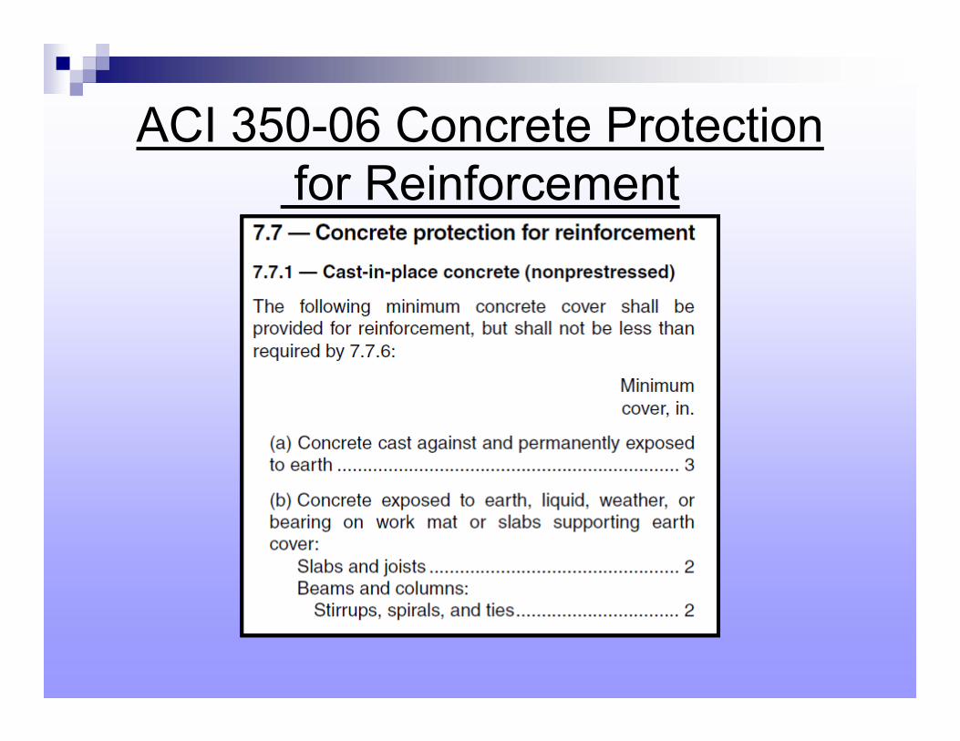
ACI 350-06 Concrete Protectionfor Reinforcement
30
ACI 318-99 ACI 350-01 NRCS TR-67 1980
Load Factor 1.4(D+F) + 1.7(L+H) 1.4(D) + 1.7(F+L+H) 1.8(D) + 1.8(L+H)
Durability Factor N/A 1.3 – flexure & shear1.65 – axial tension N/A
Crack control, normal exposure Z = 115 kips/in Z = 130 kips/in
Crack control, severe exposure N/A Z = 95 kips/in N/A
Max spacing, s 18 inches 12 inches 18 inches
f`c 3,000 psi 4,000 psi 4,000 psi
fy 60,000 psi 60,000 psi 40,000 psi
fs as high as 36,000 psi 27,000 psi 20,000 psi
ρdesign only upper limit of 0.75ρb only upper limit of 0.75ρb ρshy = 0.31ρb
ρmin 0.00333 0.00333 0.00500
Min T & S ratio 0.0018 0.0030 0.0030
cs
cf
s 5.2540
Comparison of ACI 318-99, ACI 350-01, and NRCS TR 67
ACI 350-01&06 Exposure Definitions.pptx
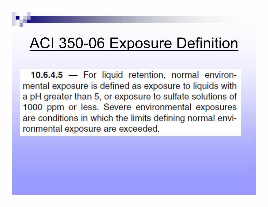
ACI 350-06 Exposure Definition
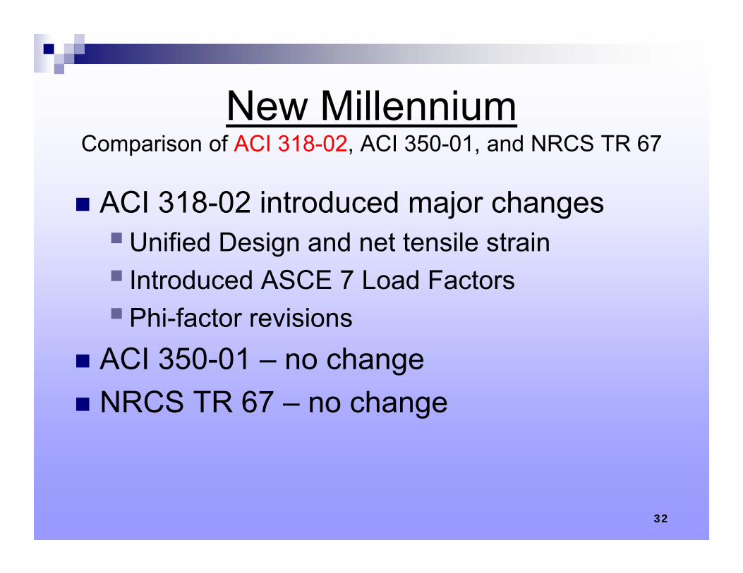
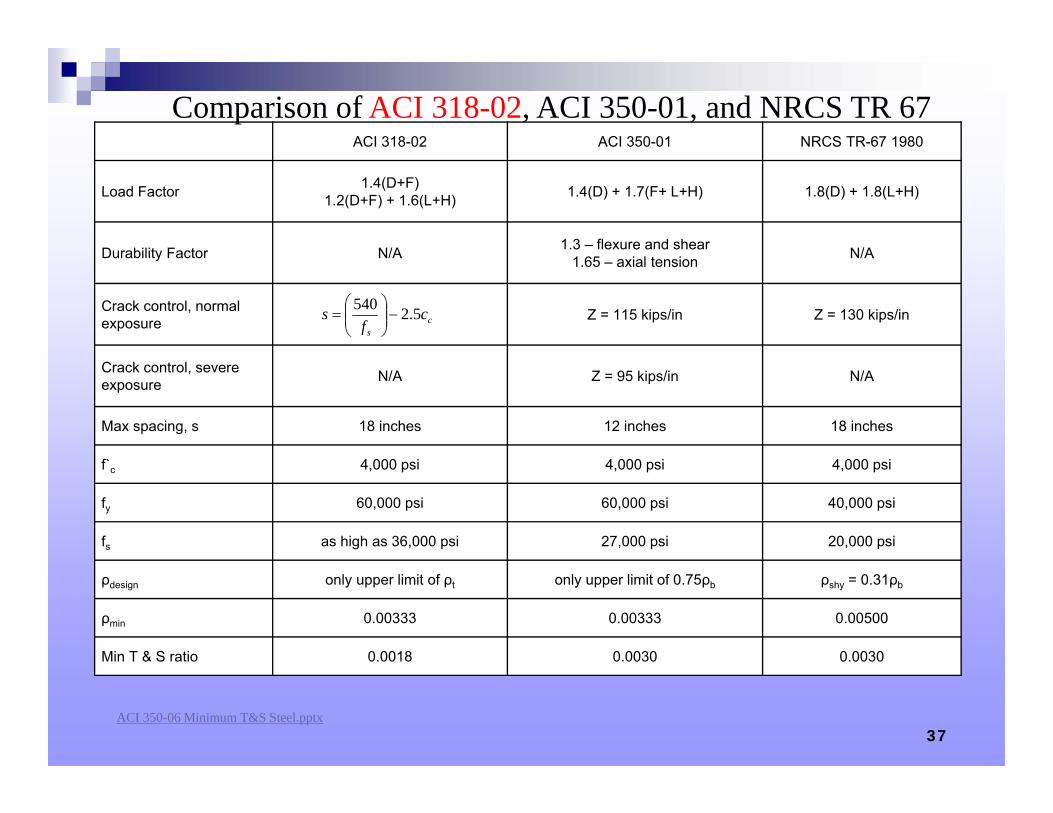
New MillenniumComparison of ACI 318-02, ACI 350-01, and NRCS TR 67
ACI 318-02 introduced major changesUnified Design and net tensile strain Introduced ASCE 7 Load FactorsPhi-factor revisions
ACI 350-01 – no change NRCS TR 67 – no change
32
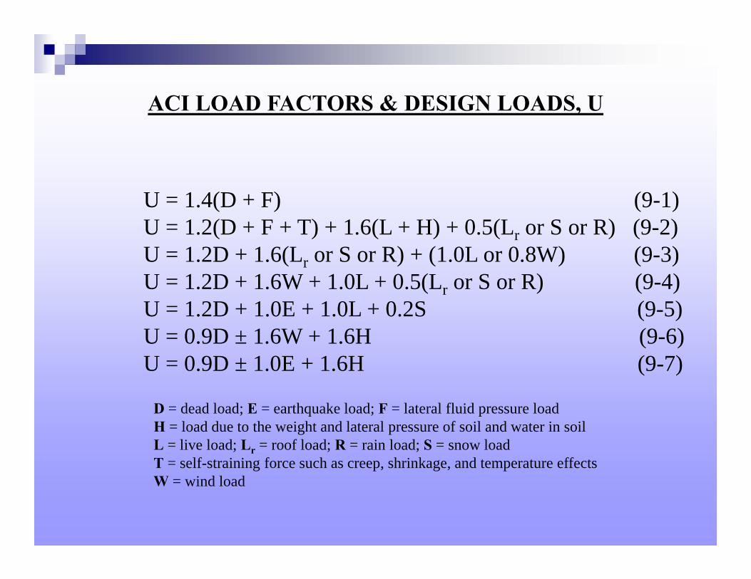
ACI LOAD FACTORS & DESIGN LOADS, U
U = 1.4(D + F) (9-1)U = 1.2(D + F + T) + 1.6(L + H) + 0.5(Lr or S or R) (9-2)U = 1.2D + 1.6(Lr or S or R) + (1.0L or 0.8W) (9-3)U = 1.2D + 1.6W + 1.0L + 0.5(Lr or S or R) (9-4)U = 1.2D + 1.0E + 1.0L + 0.2S (9-5)U = 0.9D ± 1.6W + 1.6H (9-6)U = 0.9D ± 1.0E + 1.6H (9-7)
D = dead load; E = earthquake load; F = lateral fluid pressure loadH = load due to the weight and lateral pressure of soil and water in soilL = live load; Lr = roof load; R = rain load; S = snow loadT = self-straining force such as creep, shrinkage, and temperature effectsW = wind load
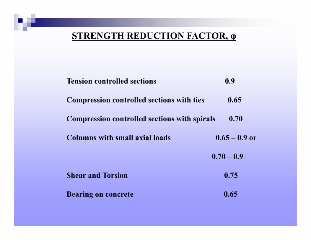
STRENGTH REDUCTION FACTOR, φ
Tension controlled sections 0.9
Compression controlled sections with ties 0.65
Compression controlled sections with spirals 0.70
Columns with small axial loads 0.65 – 0.9 or
0.70 – 0.9
Shear and Torsion 0.75
Bearing on concrete 0.65
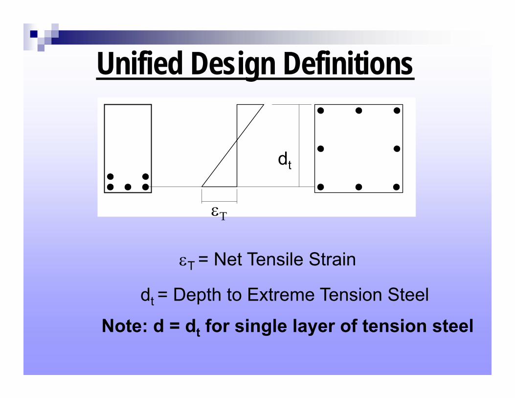
Unified Design Definitions
T = Net Tensile Strain
dt = Depth to Extreme Tension Steel
T
dt
Note: d = dt for single layer of tension steel
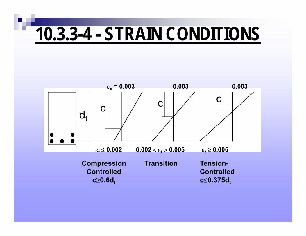
10.3.3-4 - STRAIN CONDITIONS
dtc c c
c = 0.003 0.003 0.003
t 0.002 0.002 t 0.005 t 0.005
CompressionControlled
c0.6dt
Transition Tension-Controlled c0.375dt
37
ACI 318-02 ACI 350-01 NRCS TR-67 1980
Load Factor 1.4(D+F)1.2(D+F) + 1.6(L+H) 1.4(D) + 1.7(F+ L+H) 1.8(D) + 1.8(L+H)
Durability Factor N/A 1.3 – flexure and shear1.65 – axial tension N/A
Crack control, normal exposure Z = 115 kips/in Z = 130 kips/in
Crack control, severe exposure N/A Z = 95 kips/in N/A
Max spacing, s 18 inches 12 inches 18 inches
f`c 4,000 psi 4,000 psi 4,000 psi
fy 60,000 psi 60,000 psi 40,000 psi
fs as high as 36,000 psi 27,000 psi 20,000 psi
ρdesign only upper limit of ρt only upper limit of 0.75ρb ρshy = 0.31ρb
ρmin 0.00333 0.00333 0.00500
Min T & S ratio 0.0018 0.0030 0.0030
cs
cf
s 5.2540
Comparison of ACI 318-02, ACI 350-01, and NRCS TR 67
ACI 350-06 Minimum T&S Steel.pptx
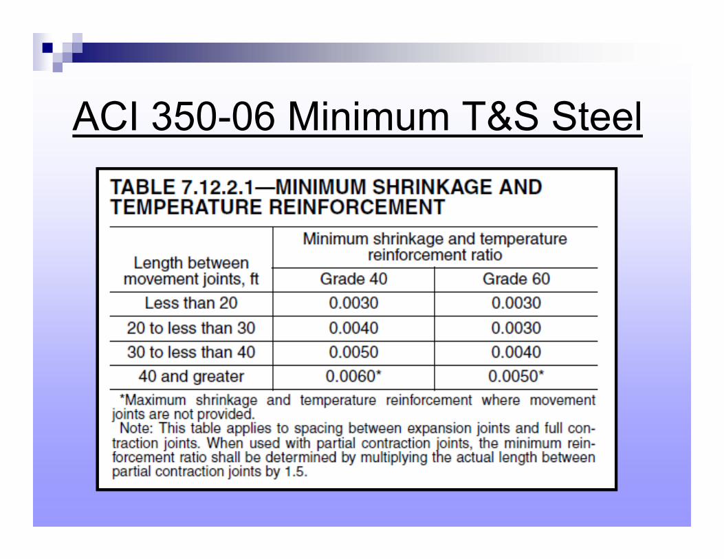
ACI 350-06 Minimum T&S Steel
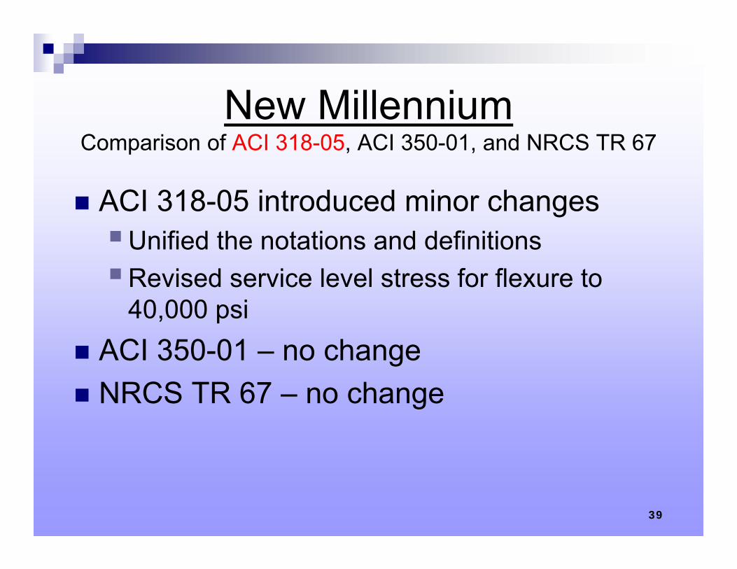
New MillenniumComparison of ACI 318-05, ACI 350-01, and NRCS TR 67
ACI 318-05 introduced minor changesUnified the notations and definitionsRevised service level stress for flexure to
40,000 psi ACI 350-01 – no change NRCS TR 67 – no change
39
40
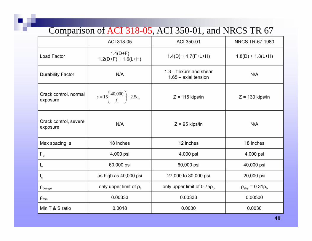
ACI 318-05 ACI 350-01 NRCS TR-67 1980
Load Factor 1.4(D+F)1.2(D+F) + 1.6(L+H) 1.4(D) + 1.7(F+L+H) 1.8(D) + 1.8(L+H)
Durability Factor N/A 1.3 – flexure and shear1.65 – axial tension N/A
Crack control, normal exposure Z = 115 kips/in Z = 130 kips/in
Crack control, severe exposure N/A Z = 95 kips/in N/A
Max spacing, s 18 inches 12 inches 18 inches
f`c 4,000 psi 4,000 psi 4,000 psi
fy 60,000 psi 60,000 psi 40,000 psi
fs as high as 40,000 psi 27,000 to 30,000 psi 20,000 psi
ρdesign only upper limit of ρt only upper limit of 0.75ρb ρshy = 0.31ρb
ρmin 0.00333 0.00333 0.00500
Min T & S ratio 0.0018 0.0030 0.0030
cs
cf
s 5.2000,4015
Comparison of ACI 318-05, ACI 350-01, and NRCS TR 67
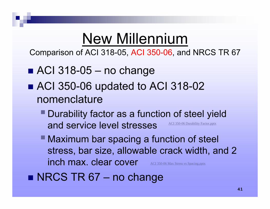
New MillenniumComparison of ACI 318-05, ACI 350-06, and NRCS TR 67
ACI 318-05 – no change ACI 350-06 updated to ACI 318-02
nomenclatureDurability factor as a function of steel yield
and service level stressesMaximum bar spacing a function of steel
stress, bar size, allowable crack width, and 2 inch max. clear cover
NRCS TR 67 – no change41
ACI 350-06 Durability Factor.pptx
ACI 350-06 Max Stress vs Spacing.pptx
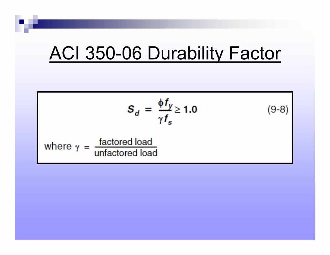
ACI 350-06 Durability Factor
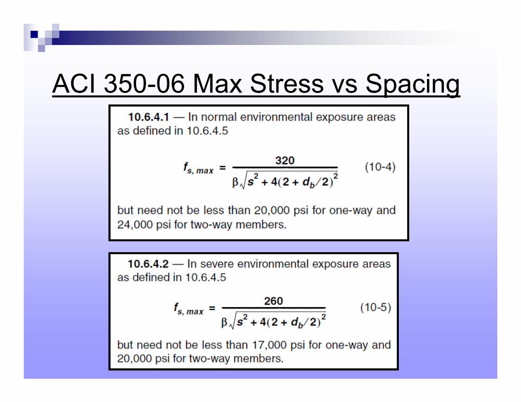
ACI 350-06 Max Stress vs Spacing
44
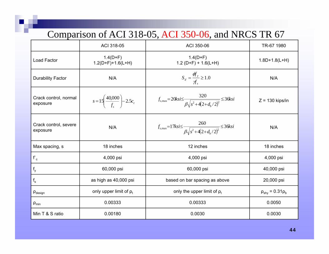
ACI 318-05 ACI 350-06 TR-67 1980
Load Factor 1.4(D+F)1.2(D+F)+1.6(L+H)
1.4(D+F)1.2 (D+F) + 1.6(L+H) 1.8D+1.8(L+H)
Durability Factor N/A N/A
Crack control, normal exposure Z = 130 kips/in
Crack control, severe exposure N/A N/A
Max spacing, s 18 inches 12 inches 18 inches
f`c 4,000 psi 4,000 psi 4,000 psi
fy 60,000 psi 60,000 psi 40,000 psi
fs as high as 40,000 psi based on bar spacing as above 20,000 psi
ρdesign only upper limit of ρt only the upper limit of ρt ρshy = 0.31ρb
ρmin 0.00333 0.00333 0.0050
Min T & S ratio 0.00180 0.0030 0.0030
0.1s
yd f
fS
cs
cf
s 5.2000,4015
ksids
ksifb
s 362/24
3202022max,
ksi
dsksif
b
s 362/24
2601722max,
Comparison of ACI 318-05, ACI 350-06, and NRCS TR 67
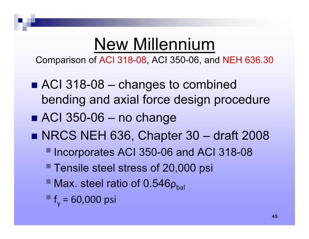
New MillenniumComparison of ACI 318-08, ACI 350-06, and NEH 636.30
ACI 318-08 – changes to combined bending and axial force design procedure
ACI 350-06 – no change NRCS NEH 636, Chapter 30 – draft 2008 Incorporates ACI 350-06 and ACI 318-08Tensile steel stress of 20,000 psiMax. steel ratio of 0.546ρbal fy = 60,000 psi
45
46
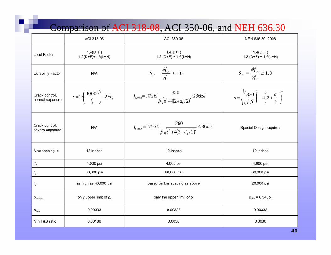
ACI 318-08 ACI 350-06 NEH 636.30 2008
Load Factor 1.4(D+F)1.2(D+F)+1.6(L+H)
1.4(D+F)1.2 (D+F) + 1.6(L+H)
1.4(D+F)1.2 (D+F) + 1.6(L+H)
Durability Factor N/A
Crack control, normal exposure
Crack control, severe exposure N/A Special Design required
Max spacing, s 18 inches 12 inches 12 inches
f`c 4,000 psi 4,000 psi 4,000 psi
fy 60,000 psi 60,000 psi 60,000 psi
fs as high as 40,000 psi based on bar spacing as above 20,000 psi
ρdesign only upper limit of ρt only the upper limit of ρt ρshy = 0.546ρb
ρmin 0.00333 0.00333 0.00333
Min T&S ratio 0.00180 0.0030 0.0030
0.1s
yd f
fS
0.1s
yd f
fS
cs
cf
s 5.2000,4015
ksi
dsksif
b
s 362/24
3202022max,
22
224320
b
s
df
s
ksi
dsksif
b
s 362/24
2601722max,
Comparison of ACI 318-08, ACI 350-06, and NEH 636.30
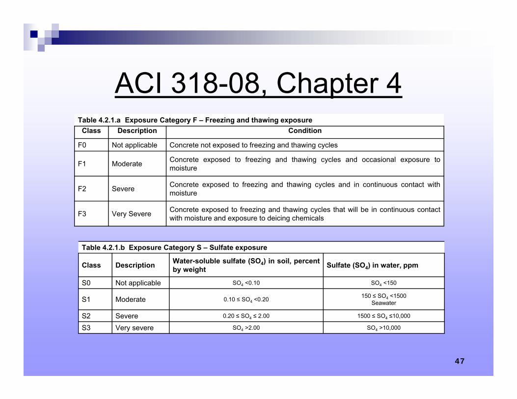
ACI 318-08, Chapter 4
47
Table 4.2.1.a Exposure Category F – Freezing and thawing exposureClass Description Condition
F0 Not applicable Concrete not exposed to freezing and thawing cycles
F1 Moderate Concrete exposed to freezing and thawing cycles and occasional exposure tomoisture
F2 Severe Concrete exposed to freezing and thawing cycles and in continuous contact withmoisture
F3 Very Severe Concrete exposed to freezing and thawing cycles that will be in continuous contactwith moisture and exposure to deicing chemicals
Table 4.2.1.b Exposure Category S – Sulfate exposure
Class Description Water-soluble sulfate (SO4) in soil, percentby weight Sulfate (SO4) in water, ppm
S0 Not applicable SO4 <0.10 SO4 <150
S1 Moderate 0.10 ≤ SO4 <0.20 150 ≤ SO4 <1500Seawater
S2 Severe 0.20 ≤ SO4 ≤ 2.00 1500 ≤ SO4 ≤10,000
S3 Very severe SO4 >2.00 SO4 >10,000
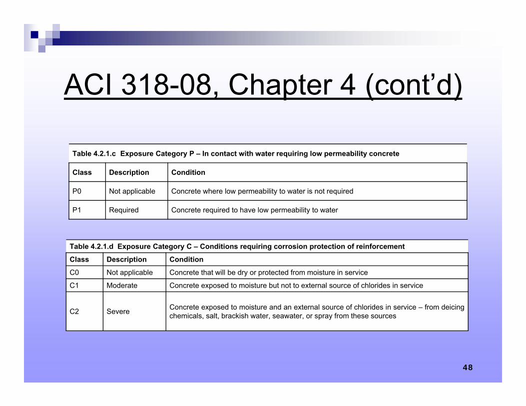
ACI 318-08, Chapter 4 (cont’d)
48
Table 4.2.1.c Exposure Category P – In contact with water requiring low permeability concrete
Class Description Condition
P0 Not applicable Concrete where low permeability to water is not required
P1 Required Concrete required to have low permeability to water
Table 4.2.1.d Exposure Category C – Conditions requiring corrosion protection of reinforcement
Class Description Condition
C0 Not applicable Concrete that will be dry or protected from moisture in service
C1 Moderate Concrete exposed to moisture but not to external source of chlorides in service
C2 Severe Concrete exposed to moisture and an external source of chlorides in service – from deicingchemicals, salt, brackish water, seawater, or spray from these sources
49
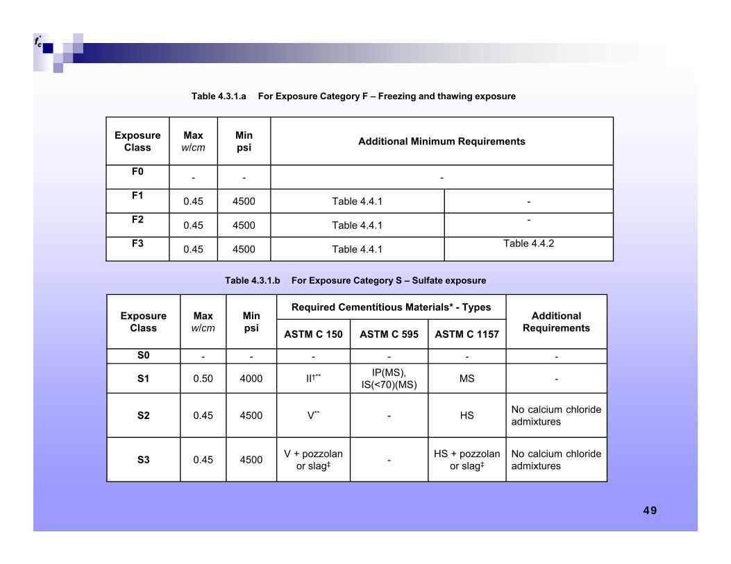
Exposure Class
Max w/cm
Min psi Additional Minimum Requirements
F0 - - -
F1 0.45 4500 Table 4.4.1 -
F2 0.45 4500 Table 4.4.1 -
F3 0.45 4500 Table 4.4.1 Table 4.4.2
Table 4.3.1.a For Exposure Category F – Freezing and thawing exposure
'cf
Exposure Class
Max w/cm
Min psi
Required Cementitious Materials* - TypesAdditional
RequirementsASTM C 150 ASTM C 595 ASTM C 1157
S0 - - - - - -
S1 0.50 4000 II†** IP(MS), IS(<70)(MS) MS -
S2 0.45 4500 V** - HS No calcium chlorideadmixtures
S3 0.45 4500 V + pozzolan or slag‡ - HS + pozzolan
or slag‡No calcium chlorideadmixtures
Table 4.3.1.b For Exposure Category S – Sulfate exposure
'cf
50
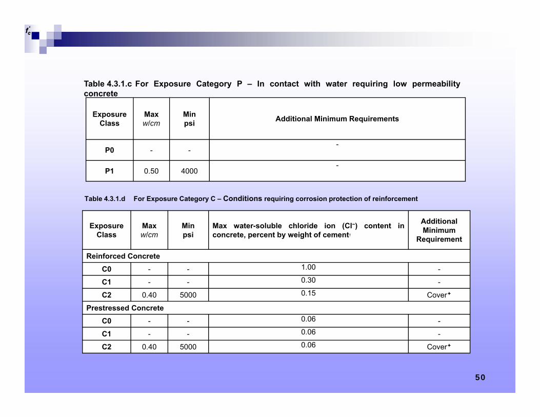
Exposure Class
Max w/cm
Min psi Additional Minimum Requirements
P0 - --
P1 0.50 4000-
Table 4.3.1.c For Exposure Category P – In contact with water requiring low permeabilityconcrete
'cf
Exposure Class
Max w/cm
Min psi
Max water-soluble chloride ion (Cl−) content inconcrete, percent by weight of cement†
Additional Minimum
Requirement
Reinforced ConcreteC0 - - 1.00 -
C1 - - 0.30 -
C2 0.40 5000 0.15 Cover
Prestressed ConcreteC0 - - 0.06 -
C1 - - 0.06 -
C2 0.40 5000 0.06 Cover
Table 4.3.1.d For Exposure Category C – Conditions requiring corrosion protection of reinforcement
'cf
51
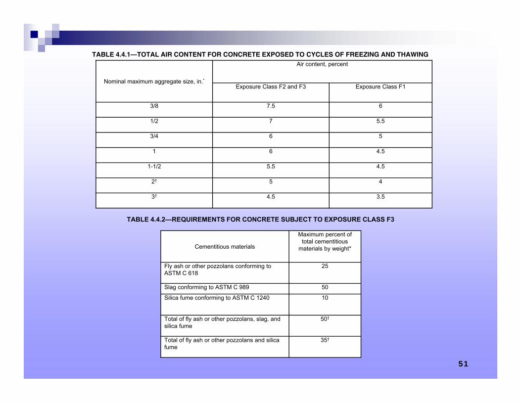
Nominal maximum aggregate size, in.*
Air content, percent
Exposure Class F2 and F3 Exposure Class F1
3/8 7.5 6
1/2 7 5.5
3/4 6 5
1 6 4.5
1-1/2 5.5 4.5
2† 5 4
3† 4.5 3.5
TABLE 4.4.1—TOTAL AIR CONTENT FOR CONCRETE EXPOSED TO CYCLES OF FREEZING AND THAWING
Cementitious materials
Maximum percent of total cementitious
materials by weight*
Fly ash or other pozzolans conforming to ASTM C 618
25
Slag conforming to ASTM C 989 50
Silica fume conforming to ASTM C 1240 10
Total of fly ash or other pozzolans, slag, and silica fume
50†
Total of fly ash or other pozzolans and silica fume
35†
TABLE 4.4.2—REQUIREMENTS FOR CONCRETE SUBJECT TO EXPOSURE CLASS F3
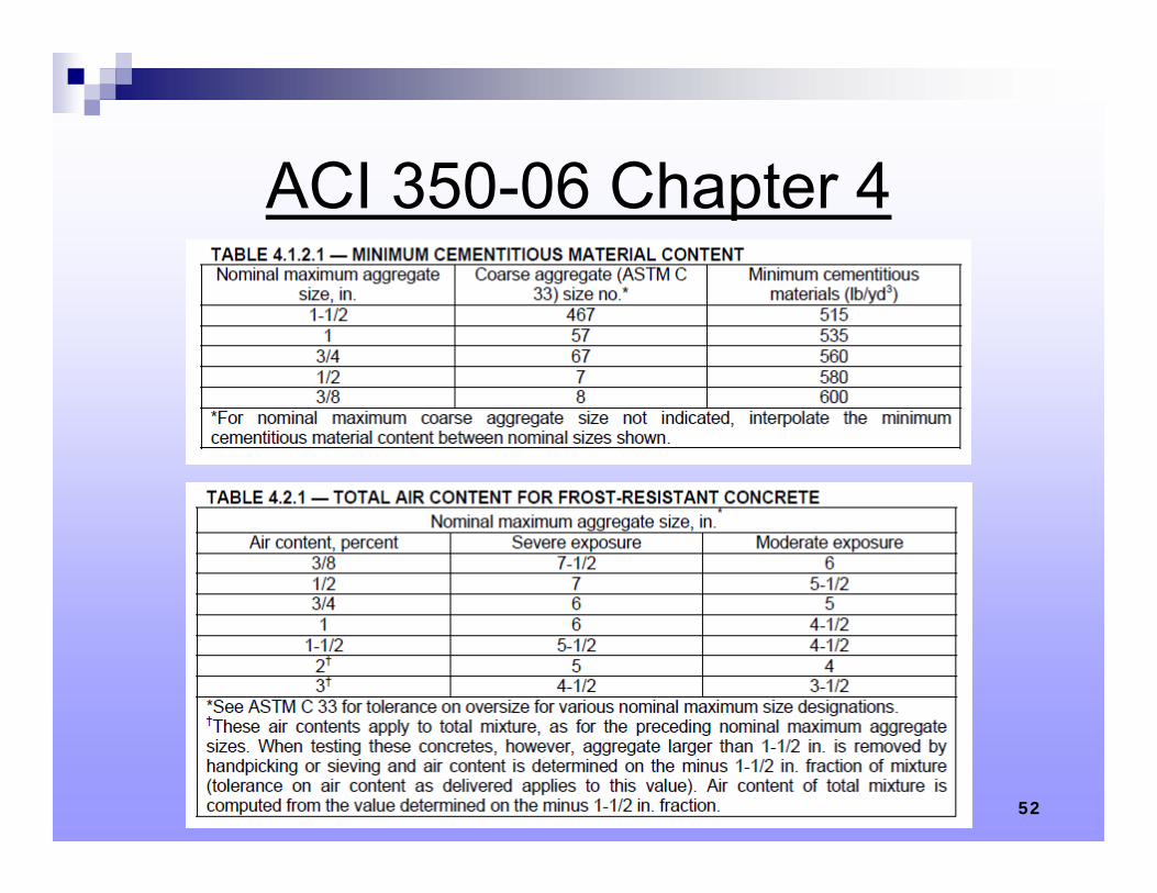
ACI 350-06 Chapter 4
52
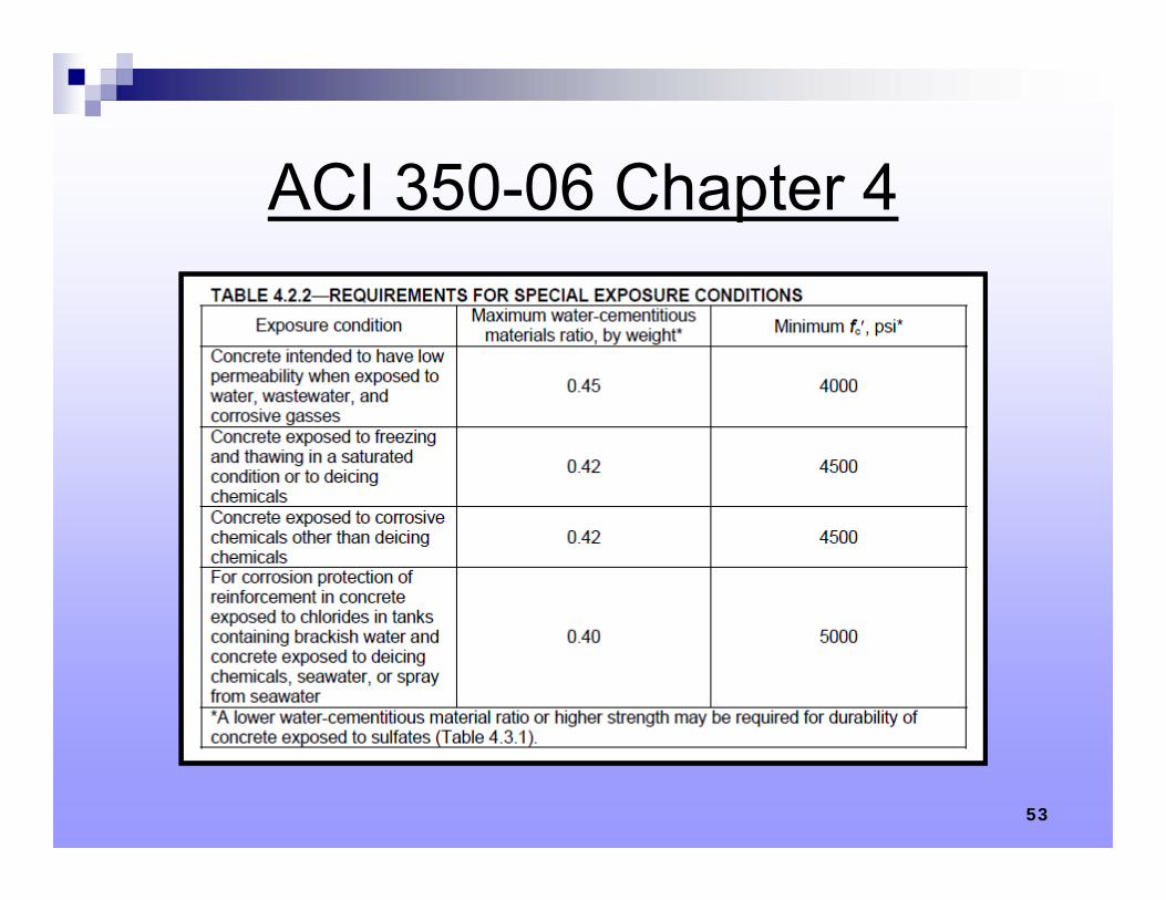
ACI 350-06 Chapter 4
53
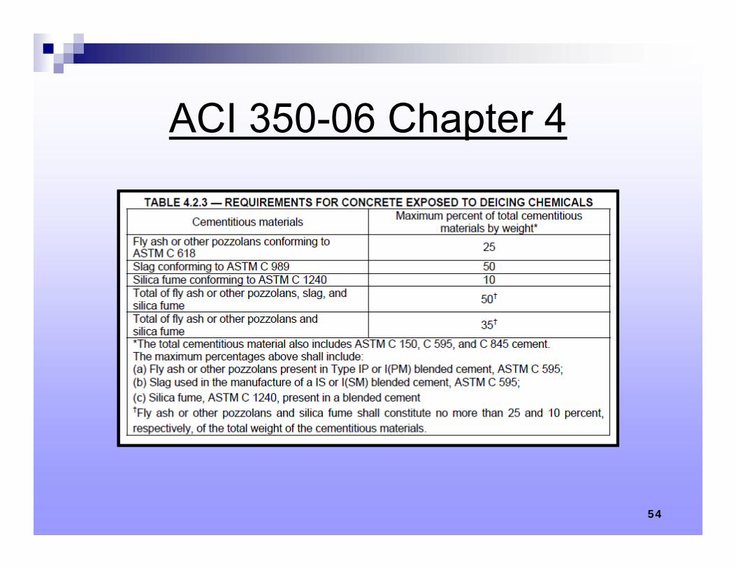
ACI 350-06 Chapter 4
54
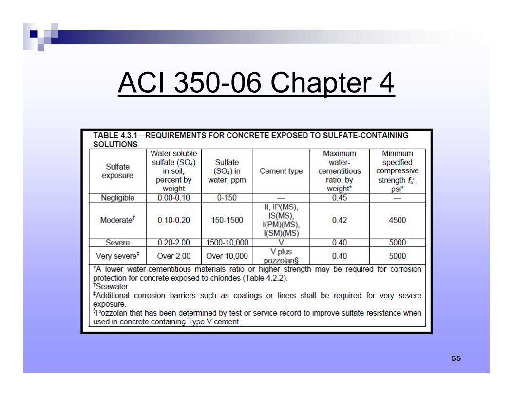
ACI 350-06 Chapter 4
55
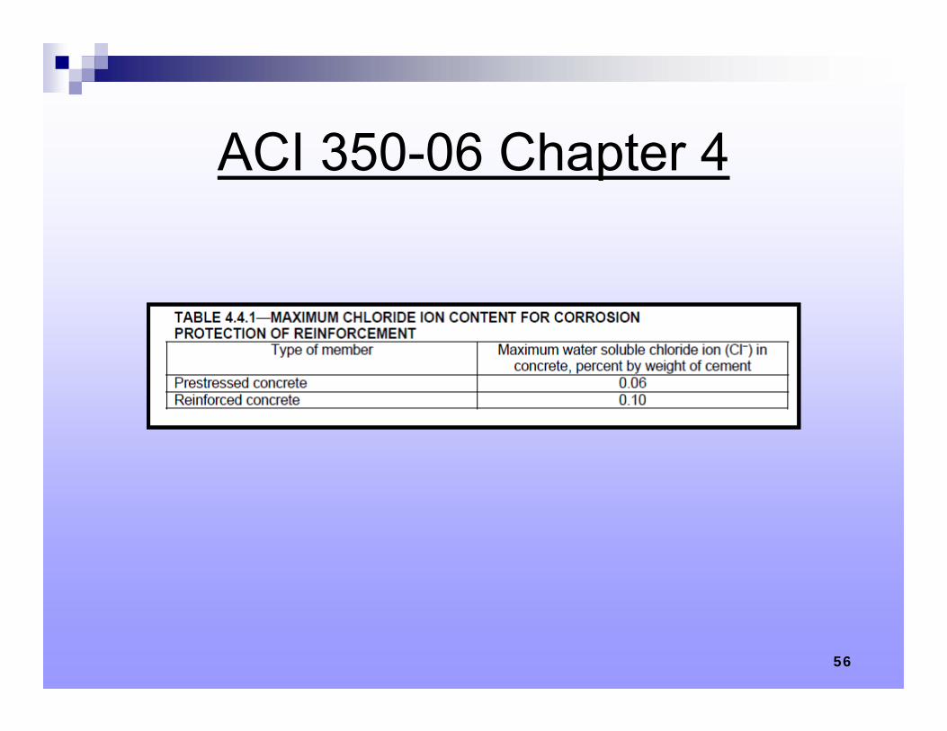
ACI 350-06 Chapter 4
56
Environmental Engineering Concrete Structures
Flexural Design Eq’ns
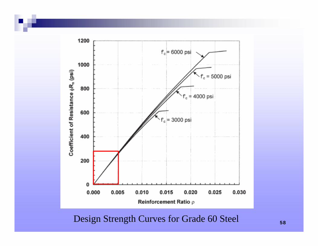
58Design Strength Curves for Grade 60 Steel
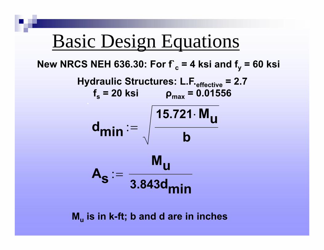
dmin15.721 Mu
b
AsMu
3.843dmin
Basic Design Equations
Mu is in k-ft; b and d are in inches
New NRCS NEH 636.30: For f`c = 4 ksi and fy = 60 ksi
Hydraulic Structures: L.F.effective = 2.7fs = 20 ksi ρmax = 0.01556
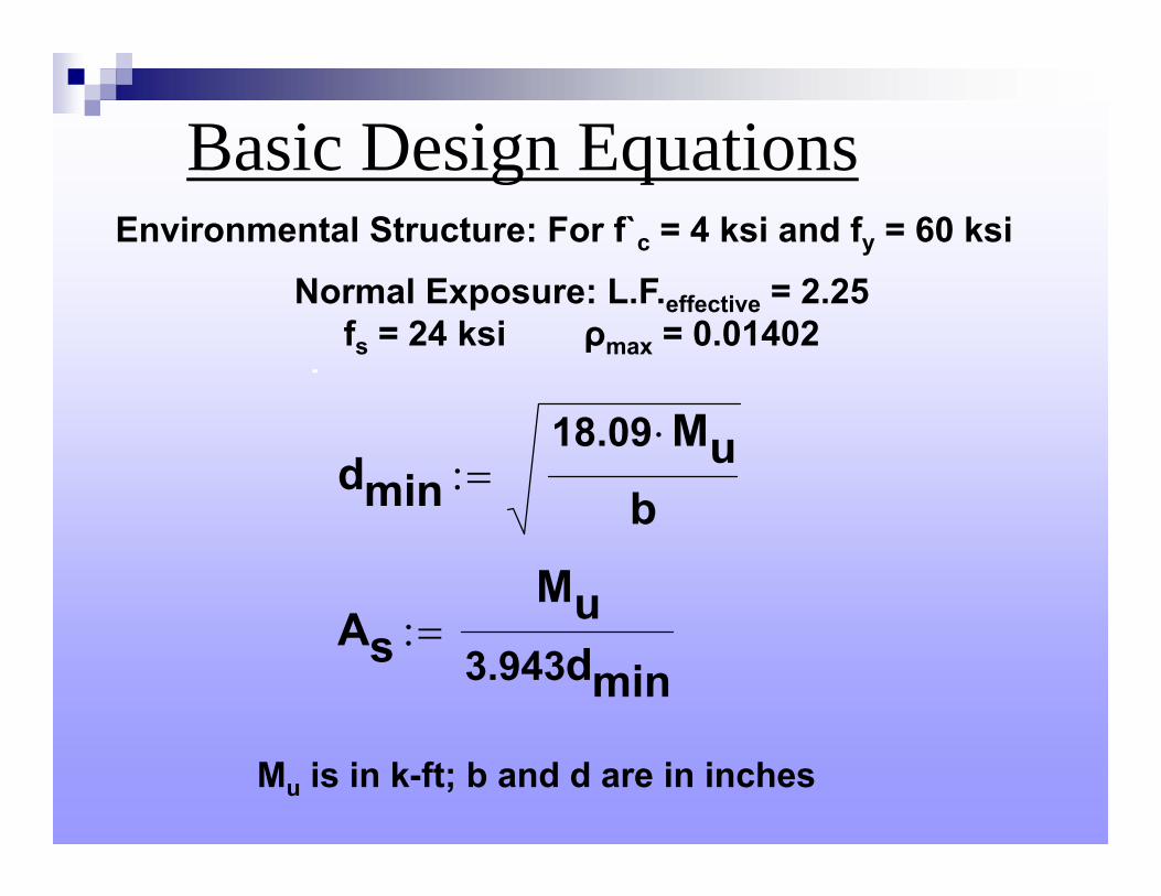
dmin18.09 Mu
b
AsMu
3.943dmin
Basic Design Equations
Mu is in k-ft; b and d are in inches
Environmental Structure: For f`c = 4 ksi and fy = 60 ksi
Normal Exposure: L.F.effective = 2.25fs = 24 ksi ρmax = 0.01402
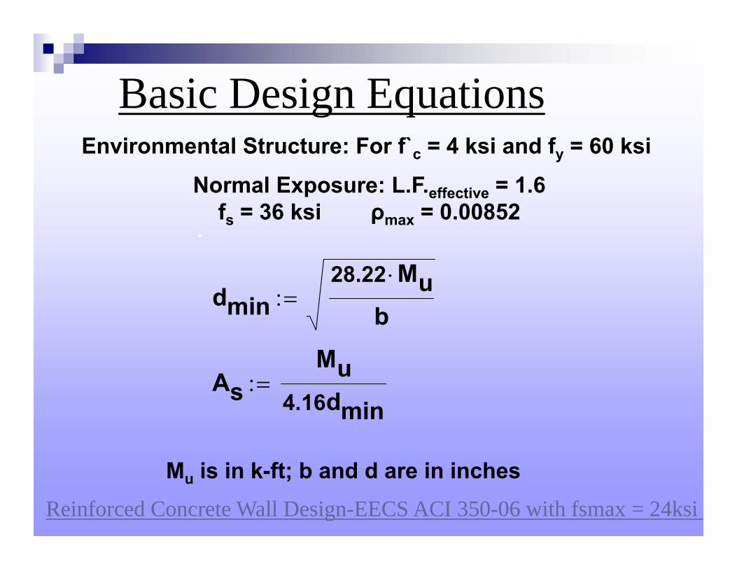
dmin28.22 Mu
b
AsMu
4.16dmin
Basic Design Equations
Mu is in k-ft; b and d are in inches
Environmental Structure: For f`c = 4 ksi and fy = 60 ksi
Normal Exposure: L.F.effective = 1.6fs = 36 ksi ρmax = 0.00852
Reinforced Concrete Wall Design-EECS ACI 350-06 with fsmax = 24ksi h
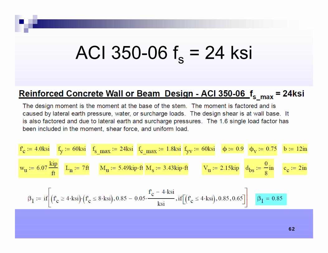
ACI 350-06 fs = 24 ksi
62
63
64
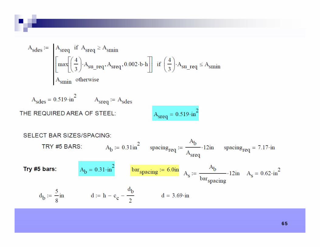
65
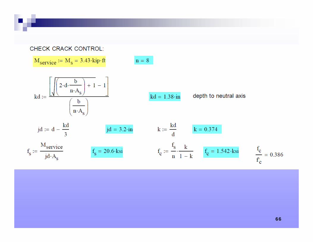
66
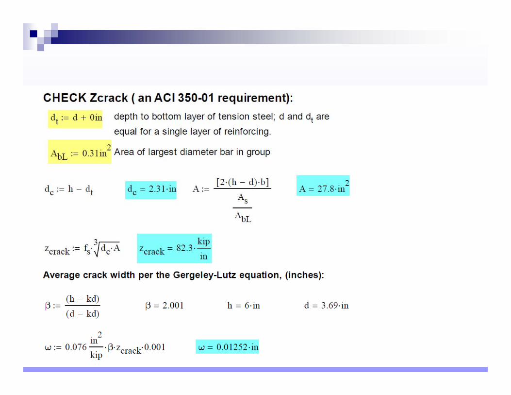
67
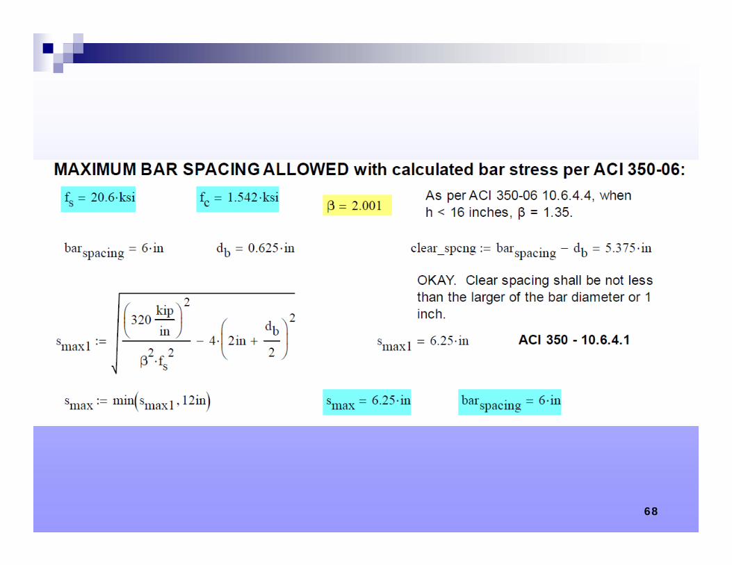
68
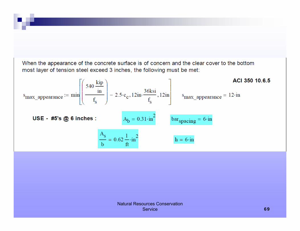
Natural Resources Conservation Service 69
70
71
72
Natural Resources Conservation Service 73
74
75
THANKS FOR PARTICIPATING!
William A. Wallace, P.E., SECB
NCSEA September 13, 2012 - Environmental Concrete Structures 76


![SNC 철근콘크리트구조 - American Concrete Institute · 2017. 8. 5. · SNC 철근콘크리트구조 Nuclear Safety-Related Concrete Structures [ACI 349 : 2013 Edition, 일치/IDT]](https://img.pdfslide.tips/doc/110x75/5fc5ef673c5f9b73870734a8/snc-eee-american-concrete-institute-2017-8-5-snc-eee.jpg)

![[RTF] member of several ACI technical committees, including ACI Committee 209, Creep and Shrinkage in Concrete, he previously chaired ACI Committee 446, Fracture Mechanics. Zich received](https://img.pdfslide.tips/doc/110x75/5b4af0d27f8b9ada3a8c9298/rtf-member-of-several-aci-technical-committees-including-aci-committee-209-creep.jpg)


![Concrete Frame Design [ACI 318-14]](https://img.pdfslide.tips/doc/110x75/577c87b51a28abe054c4d68c/concrete-frame-design-aci-318-14.jpg)