Embed Size (px)
Citation preview
Executive Summary
1
EXECUTIVE SUMMARY
ENVIRONMENTALLY FRIENDLY
INLAND WATERWAY SHIP DESIGN
FOR THE DANUBE RIVER
World Wide Fund for Nature International Danube‐Carpathian Programme
(WWF‐DCP)
Project Name: Danube Navigation Project Number: 9E0726.04 Contract Number: 066/FY09 Project Executed by: Dejan Radojcic Project Location: Republic of Serbia Date of Agreement: 01 January 2009 Short Description of Assignment: Developing concept
for ship design for the Danube River conditions
Executive Summary
2
The Report is organized as follows:
Introductory part (Report’s sections 2, 3 and 4)
First, as an introduction, restrictions of the Danube waterway (and its tributaries) are given, as restrictions in water depth, lock size and bridge heights dictate main ship dimensions. This is followed by a section (probably complicated to a non‐technical reader) on shallow water hydrodynamics which is important for design and operation of every vessel intended to navigate in inland waterways. Basic knowledge about transhipment possibilities, intermodal loading units, logistics and associated problems is also essential as these influence ship design.
Waterborne transport (Report’s sections 5 and 6)
Waterborne transport is in the focus of this study, so state‐of‐the‐art of selfpropelled vessels and barge trains follows. Special attention is given to design of selfpropelled container vessels for the Danube waterway (Section 6) as they, per se, actually do not exist (like on the Rhine).
Technical measures that make inland ships cleaner and more efficient (Report’s section 7)
A discussion on ship components (propulsors, machinery etc.) follows, as well as achievements that lead to fuel‐efficiency; this is important for the design of innovative Danube vessels. These are recent achievements in ship resistance, propulsion, engines, construction and ship utilization. Some of the achievements that are mentioned will be implemented in the designs of proposed concepts for the Danube (given in Section 8).
Proposed solutions for the Danube River (Report’s section 8)
Finally, the report includes a section on design of concepts for container and bulk cargo transport. These concepts fulfil contemporary ecological demands, apply innovative technologies, and obey existing waterway restrictions explained above. The designs proposed are a selfpropelled vessel for container transport and barge train for bulk cargo transport.
‐‐‐‐‐‐‐‐‐‐‐‐‐‐‐‐‐‐‐‐‐‐‐‐‐‐‐‐‐‐‐‐‐‐‐‐
Introductory part
Operational costs are dramatically reduced with increase of water depth, i.e. increase of vessel draught. Nevertheless, during the low water levels, the ship should be able to operate with restricted economical effects. The same ship should be able to operate in deeper water too, but will then be less efficient than the ship initially designed for deep‐water operation only. Therefore, transport costs, however calculated, are very much influenced by water depth.

Executive Summary
3
Obviously, the Danube waterway should be examined first. So:
Water depth
• On the Upper Danube the most critical stretch is between Straubing and Vilshofen with hW‐LNRL < 2 m (according to some statistics even 1.7 m).
• Several sectors on the Upper Danube (upstream to Budapest) have hW‐LNRL = 2.0 – 2.3 m.
• A few sectors on the Lower Danube (downstream of Iron Gates II) have hW‐LNRL = 2.3 – 2.4 m. According to some statistics water depth on critical sectors is as low as 1.5 m.
• Elsewhere, hW‐LNRL > 2.5 m. On the Middle Danube the depth is often over 5 m. Bridge height or air clearance
The most critical bridge heights are again on the Upper Danube, i.e. the bridges in Deggendorf and Passau with hA‐HWL = 4.73 m and 6.36 m, respectively. The height of RMD canal bridges is around 6 m. All other bridges upstream from Budapest are around 6.7 m. Downstream from Budapest hA‐HWL > 7.5 m.
Size of locks
Most of the Danube locks have standard European dimension. The most critical one is upstream of Straubing at 12 x 190 m (as all locks of RDM canal), while the rest on the Upper Danube are 2 x 24 x 190 m. The locks built by ex‐East‐European Countries are 2 x 34 x 275 (310) m.
Implications on ship design
Taking into account that a) an IWW vessel should be designed according to the particular waterway, and b) that all‐around clearance between the vessel (or her cargo) and bridge/river‐bottom/lock‐side should be at least 0.3 m, the maximal allowed vessel dimensions, with possible minor restrictions in sailing during the dry seasons, are:
• For the whole Danube including the stretch upstream of Straubing‐Vilshofen, as well as
through the DM Canal: T < 1.7 m (probably 2 m), B ≤ 11.45 m.
• Downstream of Vilshofen: T < 2.0 m (probably 2.5 m), B ≤ 23.4 m.
The length of self‐propelled vessels is practically unrestricted, while length of coupling train formation is given in the Report (Tables 2.2, 2.3 and 5.1).
Concerning the shallow water hydrodynamics the following facts are important:
• Inland (shallow water) vessels should be designed (matched) according to waterway characteristics, i.e. the vessel’s main parameters (draught, length, propeller size etc.) should be adjusted to the specific waterway.
• In the shallow water, three characteristic regimes exist: Sub‐critical (according to ITTC, below Fnh = 0.7) Critical, where PB increases dramatically due to increased resistance and decreased propulsive efficiency

Executive Summary
4
Super‐critical, where PB may be smaller than in deep water due to smaller resistance and somewhat larger propulsive efficiency.
• By far most inland vessels sail in the sub‐critical regime. Only some special, very fast, inland vessels are capable of reaching the super‐critical regime (in that case, they should pass through the critical regime as fast as possible due to enormous increase of demanded power).
• The regime borders (and appropriate speeds) depend on the water depth h, which varies from one river/river‐sector to another river/river‐sector. Consequently, subcritical/critical/ supercritical speed range is different, for instance, for the Rhine and the Danube or for Upper and Middle Danube.
• High speed vessels generate large wake (wash) which may cause serious bank erosion. So, the critical and near‐critical speeds should be avoided due to environmental reasons as well.
Concerning the costs of transport, the following is important:
• The land transport modes “dictate” prices, but also the type of intermodal loading units that should be used. So, if standard ISO containers (TEU, FEU) work well on the sea, that does not yet mean they will be so competitive in IWT. IWT should adapt itself to other modes and hence standards that are broadly used in Europe, and in particular to pallet‐wise domestic containers (EILUs) which are just 6‐16 cm wider than the usual sea containers. Nevertheless, this small difference of only few centimetres poses problems in IWT, resulting often in un‐competitiveness compared to land transport modes.
• For intermodality that integrates IWT, the following links of the transport chain are generally necessary:
So, the waterborne transport is only part of intermodal transport chain. It should be noted that the transhipment costs are often substantial and are accounted to waterborne costs.
Waterborne transport
The core of report is given at the end where two typical designs ‐ concept ships – are developed. Concepts are usually based on previous research and successful vessels. Consequently, a section on state‐of‐the‐art of waterborne transport follows, presenting selfpropelled vessels (for general, bulk and liquid cargo) and barge trains (which are more used on the Danube than on the Rhine). It is concluded that partly loaded barges can be the simplest and cheapest answer to restricted draught problems, taking into account that power needed to push an additional barge (or few of

Executive Summary
5
them) rises slightly, while cargo volume can increase rapidly. If this is the case, the problem usually poses the draught of a pushboat which cannot be reduced. So, a shallow draught pushboat would be advantageous in these situations. On the other hand, selfpropelled vessels are faster and therefore more suitable for container transport (which has to compete with land transport modes, i.e. railway and truck). Barges are by far the best for transport of large quantities of relatively cheap cargo, like bulk cargo (coal, ore, gravel, sand, grain etc.). For liquid cargo (oil and petroleum products) both ship types ‐ barge trains and selfpropelled vessels ‐ are used.
Concerning researched inland vessels (that are treated in the Study too) of particular interest are the INBISHIP, VEBIS and INBAT projects. The main reason why the innovative ship types are not applied in broader scale is economics. Namely, as already mentioned, reduced loading (resulting in lower draught navigation) seems to be the cheapest solution to adapt to dry seasons and shallow water. Consequently, the state subsidies should probably be considered as necessary to give new designs any chance to enter market.
Special attention is paid to selfpropelled container ships adapted to Danube waterway. Namely, restrictions in draught connected to waterway depth, restrictions in air draught connected to the height of bridges, and restrictions in beam and length connected to the size of locks, make numerous and serious challenges to the designer. A good inland container vessel therefore, differs significantly not only from a sea going ship, but also from one waterway to another. An optimal Danube container vessel would certainly not be the same as the optimal vessel for the Rhine or some other waterway.
Technical measures that make inland ships cleaner and more efficient
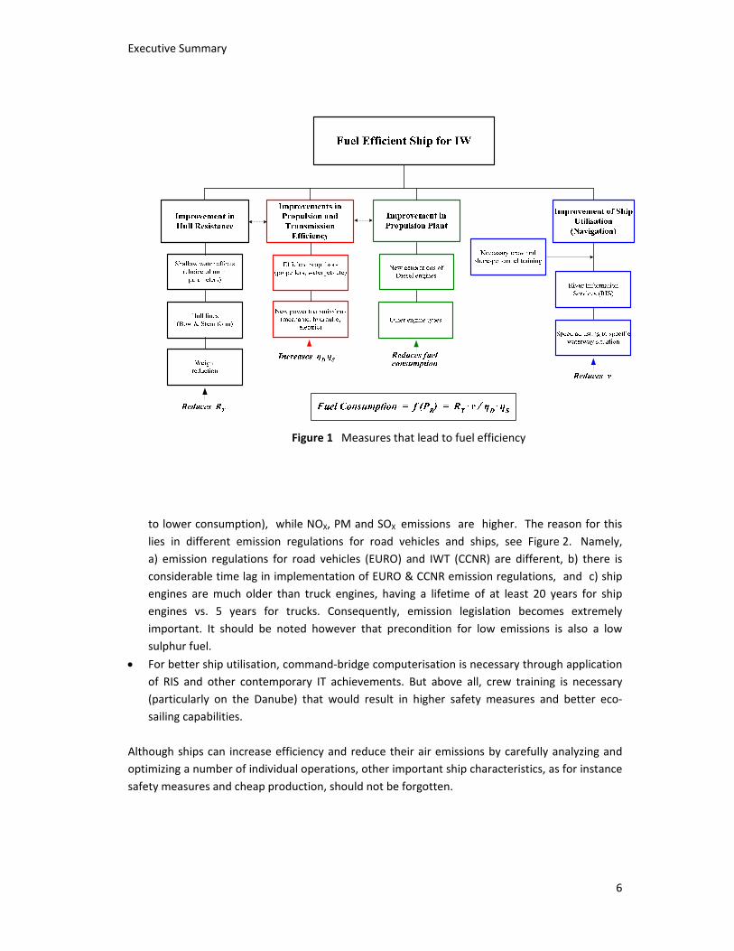
The main technical measures that enable fuel efficiency, hence cleaner and therefore more environmentally friendly shipping, are divided into four main groups, as shown in Figure 1.
In other words, it is important to:
• Involve the hydrodynamic expertise at an early design stage. Often a good, low‐resistance hull form can be obtained only if model experiments are carried out in specialized towing tanks.
• Reduce hull weight where possible (during ship production) not only by applying the latest technologies (like SPS), but in the first place by not unreasonable accumulating the additional weight by thickening the hull structure more than rules are requiring.
• New propulsor types should be considered as for instance diesel‐electric propulsors (tip‐driven or pod), rudder‐propellers etc. Nevertheless, seems that classical propeller in nozzle has reserve for additional improvements through the optimization of hull‐propulsor interaction.
• New engine types should be considered for ship applications (for the newbuildings and retrofitting), most probably derived from general application diesel engines or road vehicles. Generally speaking, ship engines only have CO2 emissions lower than the truck engines (due
Executive Summary
6
Figure 1 Measures that lead to fuel efficiency
to lower consumption), while NOX, PM and SOX emissions are higher. The reason for this lies in different emission regulations for road vehicles and ships, see Figure 2. Namely, a) emission regulations for road vehicles (EURO) and IWT (CCNR) are different, b) there is considerable time lag in implementation of EURO & CCNR emission regulations, and c) ship engines are much older than truck engines, having a lifetime of at least 20 years for ship engines vs. 5 years for trucks. Consequently, emission legislation becomes extremely important. It should be noted however that precondition for low emissions is also a low sulphur fuel.
• For better ship utilisation, command‐bridge computerisation is necessary through application of RIS and other contemporary IT achievements. But above all, crew training is necessary (particularly on the Danube) that would result in higher safety measures and better eco‐sailing capabilities.
Although ships can increase efficiency and reduce their air emissions by carefully analyzing and optimizing a number of individual operations, other important ship characteristics, as for instance safety measures and cheap production, should not be forgotten.

Executive Summary
7
Note that in this section CCNR norms are assumed to be relevant for IWT CCNR II almost corresponds to EU Stage IIIA.
Figure 2 Emission legislation for road vehicles and ships
Proposed solutions for the Danube River
With the aim to demonstrate how a contemporary, safe, cost‐effective, shallow draught vessel intended particularly for the Danube waterway should look like, some of the conclusions and technical achievements aimed at increasing efficiency of inland navigation, and discussed in the previous sections, will be incorporated into design of two specific ship types:
• Selfpropelled container vessel
• Barge train (actually a pushboat) for bulk cargo These two distinct ship type concepts are chosen because they are good representatives of typical ships used on the Danube.
Danube container ship concept
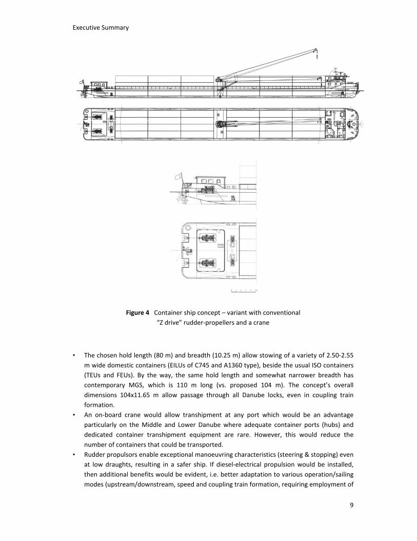
A General Arrangement plan with enlarged bow and stern part of a container ship concept (with diesel‐electric propulsion) is shown in Figure 3. Additional variant of the same concept (with conventional “Z drive” rudder‐propellers and on‐board crane 35t/30m) is depicted in Figure 4. The main particulars of the abovementioned vessels are given in Table 1.
Some of the concept’s features (underlined below) suggest an environmentally acceptable vessel with a large volume and payload capacity. At the same time, due to superior manoeuvring capabilities, the proposed concept should be safer than similar selfpropelled vessels on the Rhine and Danube. So:
• Special attention was paid to low‐draught performance. Consequently, the proposed concept should be able to operate successfully and therefore be cost‐effective at both low draught of up to 1.7 – 1.8 m (with two container layers) and full draught of up to 2.5 m (with 3 layers of full containers or even 4 layers of mixed full and empty containers). To enable this, ship form optimised for low draught navigation with relatively small propellers in nozzles of 1.35 m was adopted.

Execut
tive Summary
Table
LengthBeam HeightDraugHold leHold wHeightInstallTEU (3Payloa
F
y
e 1 Main par
h t (Depth) ht ength width t above basised power 3 layers / 4 laad capacity
Figure 3 Con
rticulars of co
m m m m m ms line m kWyers) t
ntainer ship c
ontainer ship
B
11
1
W 415
concept ‐ dies
concepts
C o n f i g uBasic W104.0 11.653.1 2.5 80.0 10.348.3 x 400 56/208 1950
sel‐electric pr
u r a t i o n With a Crane
102.5 11.65 3.1 2.5 78.5 10.34 8.3
2 x 700 134/172 1800
opulsion
e
8
Execut
• Thm (TEcodimfor
• Anpadenu
• Ruat themo
tive Summary
F
e chosen holwide domestEUs and FEUntemporary mensions 104rmation. n on‐board crticularly on edicated contumber of contudder propulslow draughten additionalodes (upstrea
y
Figure 4 Con“Z
d length (80 tic containerss). By the wMGS, which4x11.65 m a
rane would the Middle tainer transhtainers that csors enable exts, resulting i benefits woam/downstre
ntainer ship codrive” rudde
m) and breads (EILUs of C7ay, the same is 110 m lallow passage
allow transhand Lower Dhipment equiould be transxceptional man a safer shiuld be evideneam, speed an
oncept – varir‐propellers a
dth (10.25 m745 and A136e hold lengthlong (vs. proe through al
ipment at anDanube wheripment are rsported. anoeuvring cip. If diesel‐ent, i.e. betternd coupling tr
ant with convand a crane
) allow stowi60 type), besih and somewoposed 104 l Danube loc
ny port whicre adequate crare. Howeve
haracteristicselectrical propr adaptation train formatio
ventional
ng of a variede the usual what narrowem). The concks, even in
ch would be container poer, this wou
s (steering & pulsion woulto various opn, requiring e
ty of 2.50‐2.5ISO containeer breadth hancept’s overacoupling tra
an advantagorts (hubs) anld reduce th
stopping) eved be installeperation/sailinemployment
9
55 ers as all in
ge nd he
en d, ng of
Executive Summary
10
1, 2, 3 or all 4 diesel engines). This would also reduce fuel consumption (probably by 10% in upstream and even more in downstream navigation) and emission levels as engines would run at optimal RPM/loading. For refrigerated containers and other large electricity consumers (a bow thruster for instance), the same electrical network could be used, eliminating the need for auxiliary units. Conventional, mechanically‐driven rudder‐propellers have the advantage of being cheaper and retractable (hence can better adapt to water depths). Whichever propulsor type adopted, the engines should satisfy Stage IIIA/Tier 3 norms or better, enabling speed of at least 16 km/h (in deep and still water).
• Position of the engine room at the stern and the crew premises at the bow offers additional crew comfort (reduced vibrations and noise). Application of contemporary equipment and electronics enables safer sailing and lower overall operational costs.
Barge train for transport of bulk cargo
The main advantage of a push train or barge transport, compared to selfpropelled ship transport, is that cost‐effective sailing with reduced draught with partly loaded barges may be utilized. Usually it is the draught of a pushboat that poses the main problem, as it cannot be reduced below a certain level (the transom and propellers should have designed minimal draught, otherwise cannot work properly). Consequently, a low draught pushboat with a power of around 2000kW would be more than advantageous on the Danube.
If sailing with a reduced draught would be requested, then to substitute reduced carrying capacity, the number of barges in a convoy might be increased (power needed for pushing this convoy would not increase proportionally); this is actually the main advantage of pushboat technology. Suggested power of around 2000 kW would be sufficient for sailing along the whole Danube at usual push train speeds with up to six fully loaded Danube barges (carrying 1500 to 1600 t each). Tonnage capacity at reduced draught of a typical Danube barge (77x11x2.8 m) are given below:
Draught [m] ∼0.5 1.0 1.5 2.0 2.5 Tonnage [t] ‐ 300‐400 700‐800 1100‐1200 1500‐1600
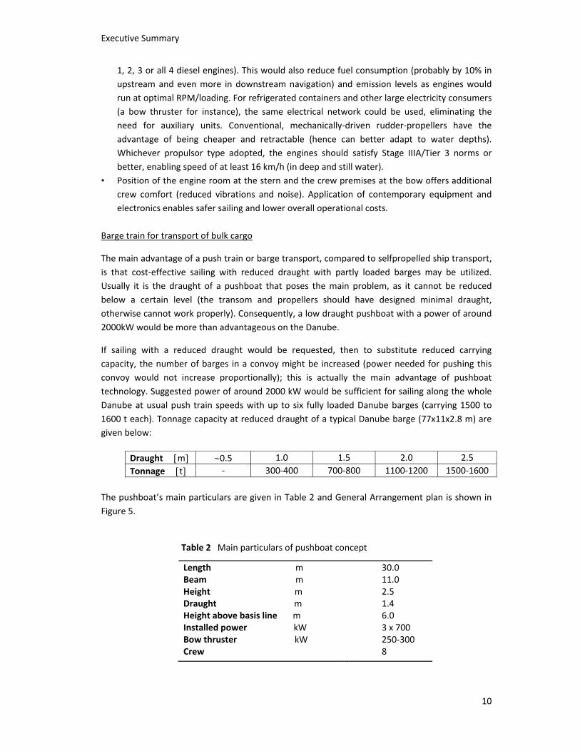
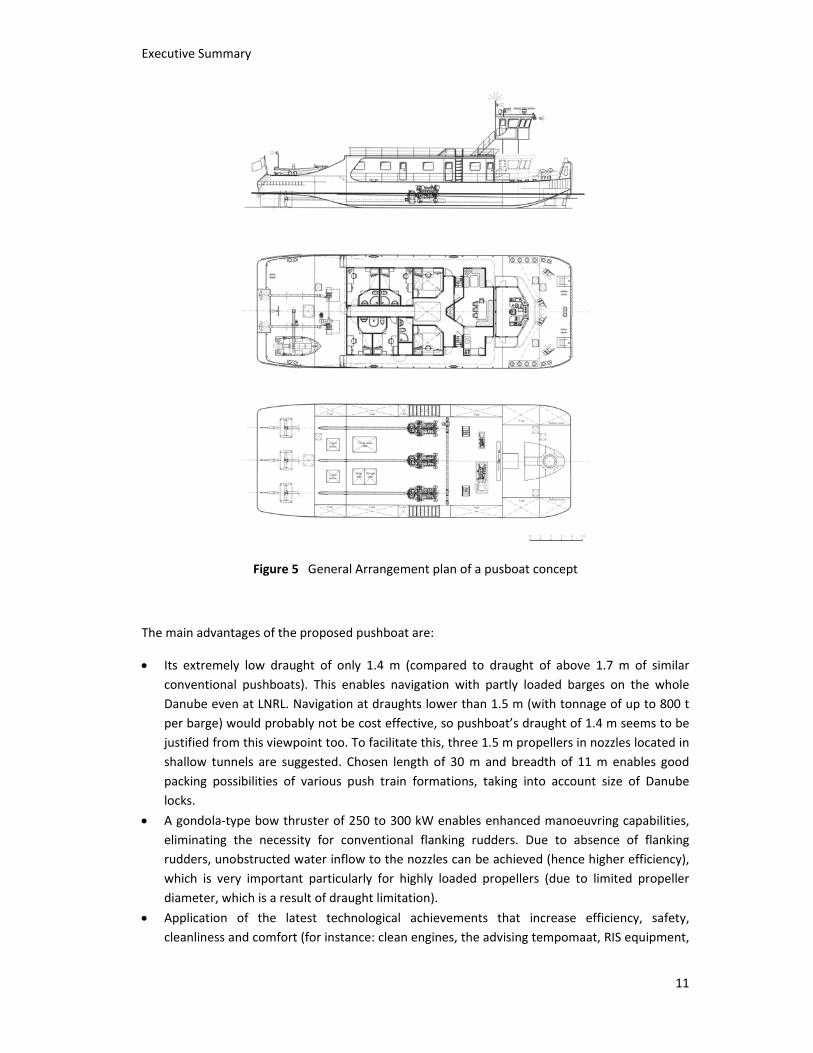
The pushboat’s main particulars are given in Table 2 and General Arrangement plan is shown in Figure 5.
Table 2 Main particulars of pushboat concept
Length mBeam m Height m Draught m Height above basis line m Installed power kW Bow thruster kW Crew
30.0 11.0 2.5 1.4 6.0 3 x 700 250‐300 8
Executive Summary
11
Figure 5 General Arrangement plan of a pusboat concept
The main advantages of the proposed pushboat are:
• Its extremely low draught of only 1.4 m (compared to draught of above 1.7 m of similar conventional pushboats). This enables navigation with partly loaded barges on the whole Danube even at LNRL. Navigation at draughts lower than 1.5 m (with tonnage of up to 800 t per barge) would probably not be cost effective, so pushboat’s draught of 1.4 m seems to be justified from this viewpoint too. To facilitate this, three 1.5 m propellers in nozzles located in shallow tunnels are suggested. Chosen length of 30 m and breadth of 11 m enables good packing possibilities of various push train formations, taking into account size of Danube locks.
• A gondola‐type bow thruster of 250 to 300 kW enables enhanced manoeuvring capabilities, eliminating the necessity for conventional flanking rudders. Due to absence of flanking rudders, unobstructed water inflow to the nozzles can be achieved (hence higher efficiency), which is very important particularly for highly loaded propellers (due to limited propeller diameter, which is a result of draught limitation).
• Application of the latest technological achievements that increase efficiency, safety, cleanliness and comfort (for instance: clean engines, the advising tempomaat, RIS equipment,
Executive Summary
12
resiliently mounted superstructure etc.). Nevertheless, these benefits are not a result of the proposed pushboat concept, but rather of a modern era. Namely, almost all Danube pushboats were built 30 or so years ago and therefore were equipped according to the standards belonging to the previous technological generation, so a newly built pushboat of any design or concept will be advantageous compared to the old (conventional) ones.
The cost of newbuildings
The expected cost for building the selfpropelled vessel and pushboat concepts are around 5‐6 million and 4‐5 million Euros, respectively. These, however, to a great extent depend on chosen equipment, shipyard, material (steel) cost, time of order etc. Therefore, variations of order of magnitude of around 10 to 20% to the abovementioned might be expected.
Concluding remarks
Previous part, ending with the custom designs of Danube selfpropelled and pushboat concepts, is actually a kind of conclusion as most of the innovations and benefits that were discussed in previous sections were incorporated in the new designs.
It should be underlined, however, that contemporary (modern) shallow draught vessels, particularly suited for the Danube waterway, are feasible and desirable. The only problem is that inherently they will be less efficient and less cost‐effective (if water is deep enough) than the vessels with deeper draught. Besides, IWT (river vessels) in general have very strong competition from other modes ‐ railway and road transport, so under the present circumstances, there may be a limit (concerning low draught navigation) under which IWT will not be cost‐effective anymore, as other modes (already much stronger and better positioned) will prevail. On the other side, when there is not enough water (when LNRL) low draught vessels will have a logistical advantage compared to deeper draught pushboats, as will be able to navigate all the year round.
Consequently, under which conditions IWT will work (i.e. what would be minimal/guaranteed water depth along the river and throughout the season, cost of fuel, taxes, eventual state subsidies etc.) is a political question which should be influenced, amongst other, by the technical and ecological requirements of IWT. Ships were navigating in the past, often transporting larger quantity of cargo than today (on the yearly basis) although navigational conditions were worse (with a lot of shallows and free‐flowing sectors), but the business environment was then different than it is today (with pipelines, railway and road infrastructure passing through the Danube corridor).
Nomenclature
B – Vessel beam (m) RT – Total resistance (kN)
FNh – Froude number based on water depth (v/√(g⋅h)) T – Vessel draught (m) hW‐LNRL – Water depth by LNRL (m) v – Vessel speed (km/h) hA‐HWL – Air clearance over HWL (m) ηD – Propulsive efficiency PB – Installed power (kW) ηS – Shaft efficiency

![WATERWAY RISK ASSESSMENT WATERWAYS MANAGEMENT PLANNING TODAY TO BE READY FOR TOMORROW PAWSA [WATERWAY NAME]](https://img.pdfslide.tips/doc/110x75/56649efb5503460f94c0d4ff/waterway-risk-assessment-waterways-management-planning-today-to-be-ready-for.jpg)


![Computer aided ship design Part 3. Optimization Methods · 2018. 1. 30. · [2008][12-2] Computer aided ship design Part 3. Optimization Methods December 2008 Prof. Kyu-Yeul Lee Department](https://img.pdfslide.tips/doc/110x75/611fa2deed948c23c4604c42/computer-aided-ship-design-part-3-optimization-methods-2018-1-30-200812-2.jpg)
![[2009] [08] Innovative ship design -Trim & Stabilityocw.snu.ac.kr/sites/default/files/NOTE/5638.pdf-Trim & Stability – Calculation of Stability in Barge ship April, 2009 Prof. Kyu-YeulLee](https://img.pdfslide.tips/doc/110x75/5e5d170fa47f740e9a1a4203/2009-08-innovative-ship-design-trim-trim-stability-a-calculation.jpg)