Embed Size (px)
Citation preview
léÉê~íáåÖ=fåëíêìÅíáçåë
NOKOMNQ
`bob`=j`=uiEìé=íç=ëÉêá~ä=åìãÄÉê=NVVKVVVF
kÉï=~ë=çÑW==
båÖäáëÜ
=
Operating Instructions (up to serial number 199.999)
This product is covered by one or more of the following US patents:
• US6454629• US6394880
• US6702649• US7522764• US7163443
Contents Sirona Dental Systems GmbHOperating Instructions CEREC MC XL
Contents
1 Dear Customer, ........................................................................................................ 5
2 General data............................................................................................................. 6
2.1 Identification of danger levels........................................................................ 62.2 Formats and symbols used ........................................................................... 72.3 Note PC / Acquisition Unit ............................................................................. 7
3 General description .................................................................................................. 8
3.1 Certification ................................................................................................... 83.2 Normal use.................................................................................................... 8
4 Safety ....................................................................................................................... 9
4.1 Basic safety information ................................................................................ 94.1.1 Prerequisites .................................................................................... 94.1.2 Maintenance and repair ................................................................... 94.1.3 Modifications to the product ............................................................. 94.1.4 Accessories...................................................................................... 10
4.2 Opening the grinding chamber door during the production process ............. 104.3 Wireless phone interference with equipment ................................................ 104.4 Disturbance of data transmission.................................................................. 10
5 Installation and startup ............................................................................................. 11
5.1 Transport and unpacking .............................................................................. 115.2 Disposal of packaging materials ................................................................... 115.3 Installation site .............................................................................................. 125.4 Commissioning.............................................................................................. 12
5.4.1 Functional elements ......................................................................... 135.4.2 Standard accessories....................................................................... 15
5.4.2.1 Instruments........................................................................ 155.4.2.2 Calibration pins.................................................................. 155.4.2.3 Torque wrench .................................................................. 16
5.4.3 Display description ........................................................................... 175.4.4 Lighting of the grinding chamber...................................................... 175.4.5 Inserting the grinding chamber sieve ............................................... 185.4.6 Connecting the bar code reader....................................................... 185.4.7 Installation ........................................................................................ 19
5.4.7.1 Connecting to the PC via LAN........................................... 195.4.7.2 Connecting the unit to the power supply ........................... 195.4.7.3 Installing the unit ............................................................... 19
61 46 885 D 34392 D 3439.201.02.19.02 12.2014
Sirona Dental Systems GmbH ContentsOperating Instructions CEREC MC XL
båÖäáëÜ
5.4.7.4 Connecting to the PC via WLAN (option) ......................... 215.4.7.5 Operating several grinding units over one access point... 225.4.7.6 Connecting to the PC via the wireless H&W interface
(optional)22
5.4.8 Filling the water tank ....................................................................... 235.4.8.1 CEREC MC XL Basic ....................................................... 235.4.8.2 CEREC MC XL with premium package ............................ 24
5.4.9 Switching the unit ON and OFF....................................................... 255.5 Repacking .................................................................................................... 265.6 Scope of supply............................................................................................ 265.7 Storage......................................................................................................... 26
6 Operation................................................................................................................. 27
6.1 Configuration (CEREC MC XL) .................................................................... 276.2 Calibrating the unit ....................................................................................... 286.3 Production process....................................................................................... 31
6.3.1 Process types.................................................................................. 316.3.1.1 Grinding ............................................................................ 316.3.1.2 Milling ............................................................................... 326.3.1.3 Milling models................................................................... 336.3.1.4 Permitted instrument combinations .................................. 33
6.3.2 Preparations .................................................................................... 346.3.3 Starting the production process....................................................... 346.3.4 Terminating the production process ................................................ 356.3.5 Information regarding the quality seal (CEREC MC XL with
premium package)36
6.4 Entering the bar code ................................................................................... 366.5 Using the manual block fixing....................................................................... 37
7 Service..................................................................................................................... 39
7.1 Changing the water ...................................................................................... 407.1.1 General information......................................................................... 407.1.2 Changing the water (CEREC MC XL Basic) ................................... 427.1.3 Changing the water (CEREC MC XL with premium package) ........ 43
7.1.3.1 Procedure for all materials except for base metals .......... 437.1.3.2 Procedure for processing base metal materials ............... 44
7.2 Instruments................................................................................................... 477.2.1 Overview of materials/instruments .................................................. 47
7.2.1.1 CEREC MC XL Basic ....................................................... 477.2.1.2 CEREC MC XL with premium package ............................ 47
7.2.2 Changing instruments ..................................................................... 477.3 Care, cleaning agents, and disinfectants ..................................................... 49
61 46 885 D 3439D 3439.201.02.19.02 12.2014 3
Contents Sirona Dental Systems GmbHOperating Instructions CEREC MC XL
7.4 Cleaning surfaces ......................................................................................... 507.4.1 Disinfecting....................................................................................... 507.4.2 Protection against medicaments ...................................................... 507.4.3 Cleaning ........................................................................................... 50
7.5 Replacing the main fuses.............................................................................. 517.6 Changing the filter ......................................................................................... 52
7.6.1 CEREC MC XL Basic....................................................................... 527.6.2 CEREC MC XL with premium package............................................ 53
7.6.2.1 Procedure for all materials except for base metals ........... 547.6.2.2 Base metal operation or mixed operation with base metal
and other materials54
7.6.3 Changing filters on the external tank................................................ 547.7 Removing water from the unit ....................................................................... 58
7.7.1 Procedure for all materials except for base metals .......................... 587.7.2 Base metal operation or mixed operation with base metal and other
materials58
7.8 Using the tank cap opener ............................................................................ 59
8 Technical description................................................................................................ 61
8.1 System requirements .................................................................................... 618.1.1 CEREC MC XL Basic....................................................................... 618.1.2 CEREC MC XL with premium package............................................ 61
8.2 Grinding and milling unit................................................................................ 618.2.1 General technical description........................................................... 618.2.2 Technical data.................................................................................. 638.2.3 Controller board ............................................................................... 63
9 Disposal.................................................................................................................... 64
Index......................................................................................................................... 65
61 46 885 D 34394 D 3439.201.02.19.02 12.2014
61 46 885 D 3439D 3439.201.02.19.02 12.2014 5
Sirona Dental Systems GmbH 1 Dear Customer,Operating Instructions CEREC MC XL
båÖäáëÜ
1 Dear Customer,General description
Thank you for your purchase of this CEREC MC XL® unit from Sirona.
This device enables you to produce dental restorations, e.g. from ceramic material with a natural appearance (CEramic REConstruction).
Improper use and handling can create hazards and cause damage. Please read and follow these operating instructions carefully and Always keep them within easy reach.
To prevent personal injury or material damage, it is important to observe all safety information.Your TeamYour CEREC MC XL team,
2 General data Sirona Dental Systems GmbH2.1 Identification of danger levels Operating Instructions CEREC MC XL
2 General dataPlease read this document completely and follow the instructions exactly. You should always keep it within reach.
Original language of the present document: German.
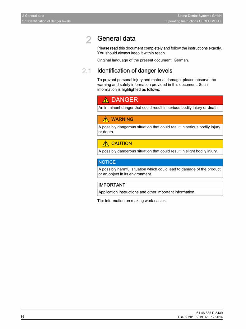
2.1 Identification of danger levelsTo prevent personal injury and material damage, please observe the warning and safety information provided in this document. Such information is highlighted as follows:
Tip: Information on making work easier.
DANGERAn imminent danger that could result in serious bodily injury or death.
WARNINGA possibly dangerous situation that could result in serious bodily injury or death.
CAUTIONA possibly dangerous situation that could result in slight bodily injury.
NOTICE A possibly harmful situation which could lead to damage of the product or an object in its environment.
IMPORTANTApplication instructions and other important information.
61 46 885 D 34396 D 3439.201.02.19.02 12.2014
Sirona Dental Systems GmbH 2 General dataOperating Instructions CEREC MC XL 2.2 Formats and symbols used
båÖäáëÜ
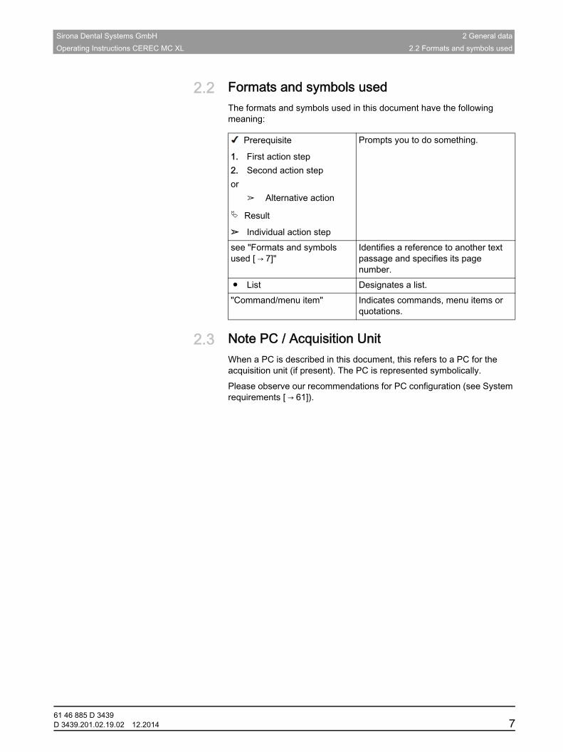
2.2 Formats and symbols usedThe formats and symbols used in this document have the following meaning:
2.3 Note PC / Acquisition UnitWhen a PC is described in this document, this refers to a PC for the acquisition unit (if present). The PC is represented symbolically.Fragment CEREC MC XLPlease observe our recommendations for PC configuration (see System requirements [ → 61]).
Prerequisite
1. First action step2. Second action stepor
➢ Alternative action
Result
➢ Individual action step
Prompts you to do something.
see "Formats and symbols used [ → 7]"
Identifies a reference to another text passage and specifies its page number.
● List Designates a list."Command/menu item" Indicates commands, menu items or
quotations.
61 46 885 D 3439D 3439.201.02.19.02 12.2014 7
61 46 885 D 34398 D 3439.201.02.19.02 12.2014
3 General description Sirona Dental Systems GmbH3.1 Certification Operating Instructions CEREC MC XL
3 General description
3.1 CertificationMachinery directive CE mark
CE mark
This product bears the CE mark in accordance with the provisions of Council Directive 2006/42/EC (machinery directive). As such, the following standards apply: DIN EN ISO 12100:2011-03, DIN EN 61010-1:2011-07 and DIN EN 61326-1:2013-07.
Examples EN 60601 + EN 60950 + UL 60950Examples of CE mark for connected products:
● EN 60601-1:2006 based on IEC 60601-1:2005
● EN 60950-1:2006 based on IEC 60950-1:2005
● UL 60950 second edition 2010
GOST mark
3.2 Normal useIntended use of MC XL+CEREC 3 SEThis unit produces computer-aided dental restorations, e.g. from natural-appearing ceramic material. It must not be used for any other purpose.Follow the operating instructionsIf the unit is used for any usage purpose other than the one mentioned above, it may be damaged.
Intended use also includes observing the present operating instructions and the relevant maintenance instructions.
For the USA only
For the USA only
CAUTION: According to US Federal Law, this product may be sold only to or by instruction of physicians, dentists, or licensed professionals.
CAUTIONCE mark for connected products
Further products which are connected to this unit must also bear the CE mark. These products must be tested according to the applicable standards.
24
CAUTIONFollow the instructions
If the instructions for operating the unit described in this document are not observed, the intended protection of the user may be impaired.
Sirona Dental Systems GmbH 4 SafetyOperating Instructions CEREC MC XL 4.1 Basic safety information
båÖäáëÜ
4 Safety
4.1 Basic safety information
4.1.1 PrerequisitesFragment everything excluding APOLLO DI
4.1.2 Maintenance and repairAs manufacturers of dental instruments and laboratory equipment, we can assume responsibility for the safety properties of the unit only if the following points are observed:
● The maintenance and repair of this unit may be performed only by Sirona or by agencies authorized by Sirona.
● Components which have failed and influence the safety of the unit must be replaced with original (OEM) spare parts.
Please request a certificate whenever you have such work performed. It should include:
● The type and scope of work.
● Any changes made in the rated parameters or working range.
● Date, name of company and signature.
4.1.3 Modifications to the productModifications to this product which may affect the safety of the operator, patients or third parties are prohibited by law!
NOTICE Important information on building installation
The building installation must be performed by a qualified expert in compliance with the national regulations. DIN VDE 0100-710 applies in Germany.
NOTICE Restrictions regarding installation site
The system is not intended for operation in areas subject to explosion hazards.
NOTICE Do not damage the unit!
The unit can be damaged if opened improperly.
It is expressly prohibited to open the unit with tools!
61 46 885 D 3439D 3439.201.02.19.02 12.2014 9
4 Safety Sirona Dental Systems GmbH4.2 Opening the grinding chamber door during the production process Operating Instructions CEREC MC XL
4.1.4 AccessoriesProduct safety of inEos X5In order to ensure product safety, this device may be operated only with original Sirona accessories or third-party accessories expressly approved by Sirona. In particular, only the power cable supplied with the unit or the corresponding original spare part may be used with the unit. The user assumes the risk of using non-approved accessories.
4.2 Opening the grinding chamber door during the production process
4.3 Wireless phone interference with equipmentThe use of mobile wireless phones in practice or hospital environments must be prohibited to ensure safe operation of the unit.
4.4 Disturbance of data transmissionNote on wireless communicationNote on wireless communication Data communication between the acquisition unit and the CEREC MC XL grinding unit should preferably be established via the wireless H&W interface or WLAN. As for all wireless connections (e.g. cell phones), heavy utilization of the available radio channels or shielding caused by building installations (e.g. metal-shielded X-ray enclosures) may impair the quality of the connection. This may become noticeable through a reduction in range and/or a slower data transmission rate. In extreme cases, it will be impossible to establish a wireless connection at all.
Sirona has selected the best possible configuration for data communication via the wireless H&W interface or WLAN, which generally provides perfect functioning of this connection. However, in individual cases unrestricted wireless data communication may be impossible for the reasons mentioned above and/or due to local circumstances. In such cases, a cable LAN connection should be selected to ensure uninterrupted operation. If the only LAN interface on the rear of the CEREC AC is occupied by another plug, remove this H&W wireless interface connection and instead connect the LAN cable with the CEREC MC XL grinding unit.
CAUTIONInstruments that continue to run
When the grinding chamber door is opened during the production process, the instruments could continue to run for a short time.
➢ Be careful not to touch the instruments with your hand or any other object during this time.
➢ Avoid opening the grinding chamber door while the grinding unit is in operation.
➢ Before you open the grinding chamber door, end any actions that are running by selecting the "Stop" key on the grinding unit or in the application software.
61 46 885 D 343910 D 3439.201.02.19.02 12.2014
Sirona Dental Systems GmbH 5 Installation and startupOperating Instructions CEREC MC XL 5.1 Transport and unpacking
båÖäáëÜ
5 Installation and startup
5.1 Transport and unpackingTransport and unpackingAll products from Sirona are carefully checked prior to shipment. Please perform an incoming inspection immediately after delivery.
1. Check the delivery note to ensure that the consignment is complete.
2. Check whether the product shows any visible signs of damage.
If return shipment is required, please use the original packaging for shipment.Fragment Drain the water CEREC MC XLThe unit must be drained prior to shipment (if it has been operated). Removing water from the unit [ → 58]Fragment: Transport without packaging
Transport without packaging
5.2 Disposal of packaging materialsThe packaging must be disposed of in compliance with the relevant national regulations. Please observe the regulations applicable in your country.
NOTICE Damage during transport
If the product was damaged during transport, please contact your carrying agent.
CAUTIONDamage to the unit or risk of injury during transport without packaging
There is a danger of the unit falling down if it is grasped by its plastic housing.
➢ The unit should always be carried by two persons.➢ Do not grasp the unit by its plastic housing.➢ Always grasp the unit by its chassis next to its feet.
61 46 885 D 3439D 3439.201.02.19.02 12.2014 11
5 Installation and startup Sirona Dental Systems GmbH5.3 Installation site Operating Instructions CEREC MC XL
5.3 Installation site
The grinding unit requires a level floor space of approx. 700 x 420 mm The height of the grinding unit is:
● with the grinding chamber door closed: 425mm
● with the grinding chamber door open: 570mm
Install the grinding unit in such a way that it is not difficult to operate the main switch.
Make sure that the ventilation slots underneath and at the back of the unit remain unobstructed. The distance between the back of the unit and the wall must at least be 10 cm.
Note that the unit weighs 43 kg!
The unit must not be installed at sites with a high level of humidity or dust!
5.4 Commissioning
CAUTIONInstall out of the reach of patients!
Do not install or operate the grinding unit in the vicinity of the patient (place it at least 1.5 m away from the patient).
NOTICE Installation in a cabinet
If the unit is installed in a cabinet, you must provide for adequate heat exchange.
The ambient temperature surrounding the unit must be between 5°C and 40°C.
NOTICE Important information on initial startup
Observe the software installation instructions!
61 46 885 D 343912 D 3439.201.02.19.02 12.2014
Sirona Dental Systems GmbH 5 Installation and startupOperating Instructions CEREC MC XL 5.4 Commissioning
båÖäáëÜ
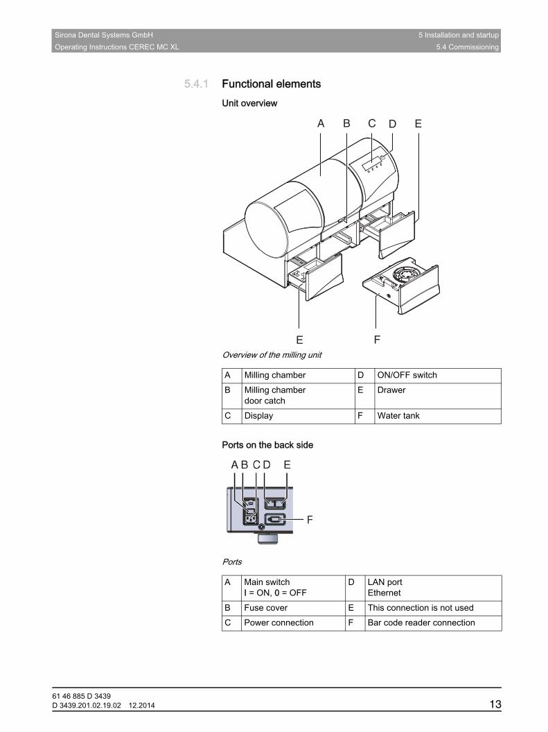
5.4.1 Functional elementsUnit overview
Overview of the milling unit
Ports on the back side
Ports on the back side
Ports
A Milling chamber D ON/OFF switchB Milling chamber
door catchE Drawer
C Display F Water tank
A B C D E
E F
A Main switchI = ON, 0 = OFF
D LAN portEthernet
B Fuse cover E This connection is not usedC Power connection F Bar code reader connection
61 46 885 D 3439D 3439.201.02.19.02 12.2014 13
5 Installation and startup Sirona Dental Systems GmbH5.4 Commissioning Operating Instructions CEREC MC XL
CEREC milling chamber
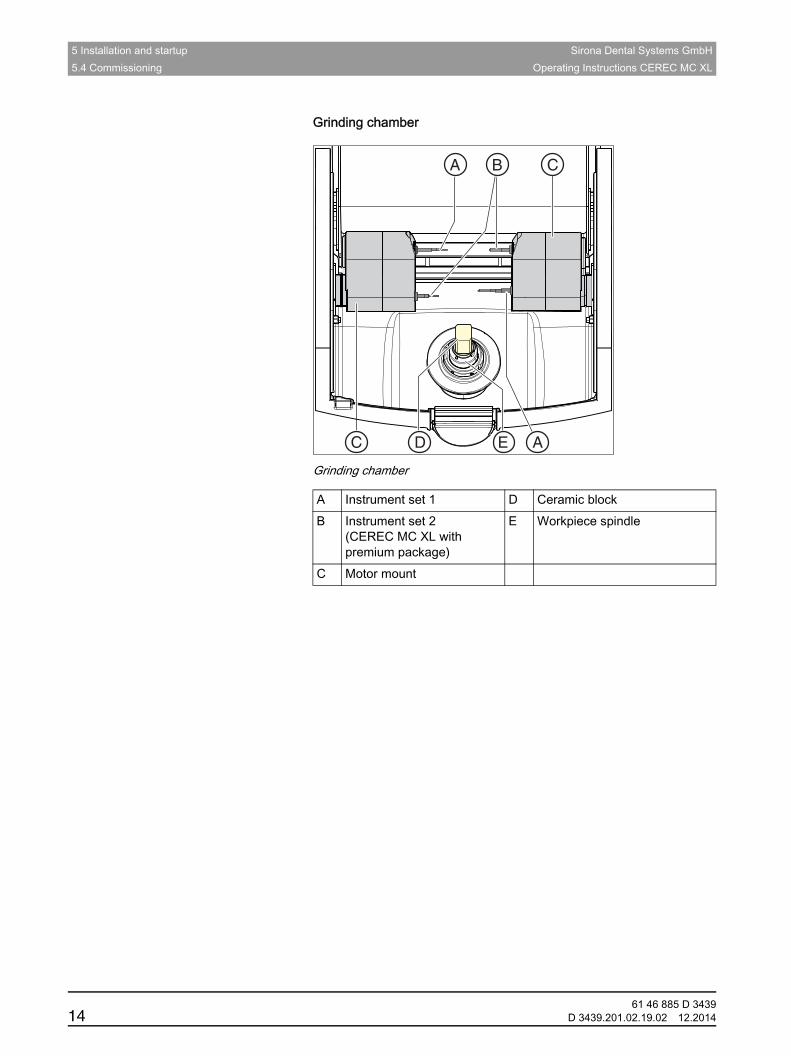
Grinding chamber
Grinding chamber
A Instrument set 1 D Ceramic blockB Instrument set 2
(CEREC MC XL with premium package)
E Workpiece spindle
C Motor mount
C
AC
A B
D E
61 46 885 D 343914 D 3439.201.02.19.02 12.2014
Sirona Dental Systems GmbH 5 Installation and startupOperating Instructions CEREC MC XL 5.4 Commissioning
båÖäáëÜ
5.4.2 Standard accessories
5.4.2.1 Instruments
The following instruments are available for production purposes. When replacing instruments, ensure the permitted instrument combinations are used (see "Permitted instrument combinations [ → 33]“).
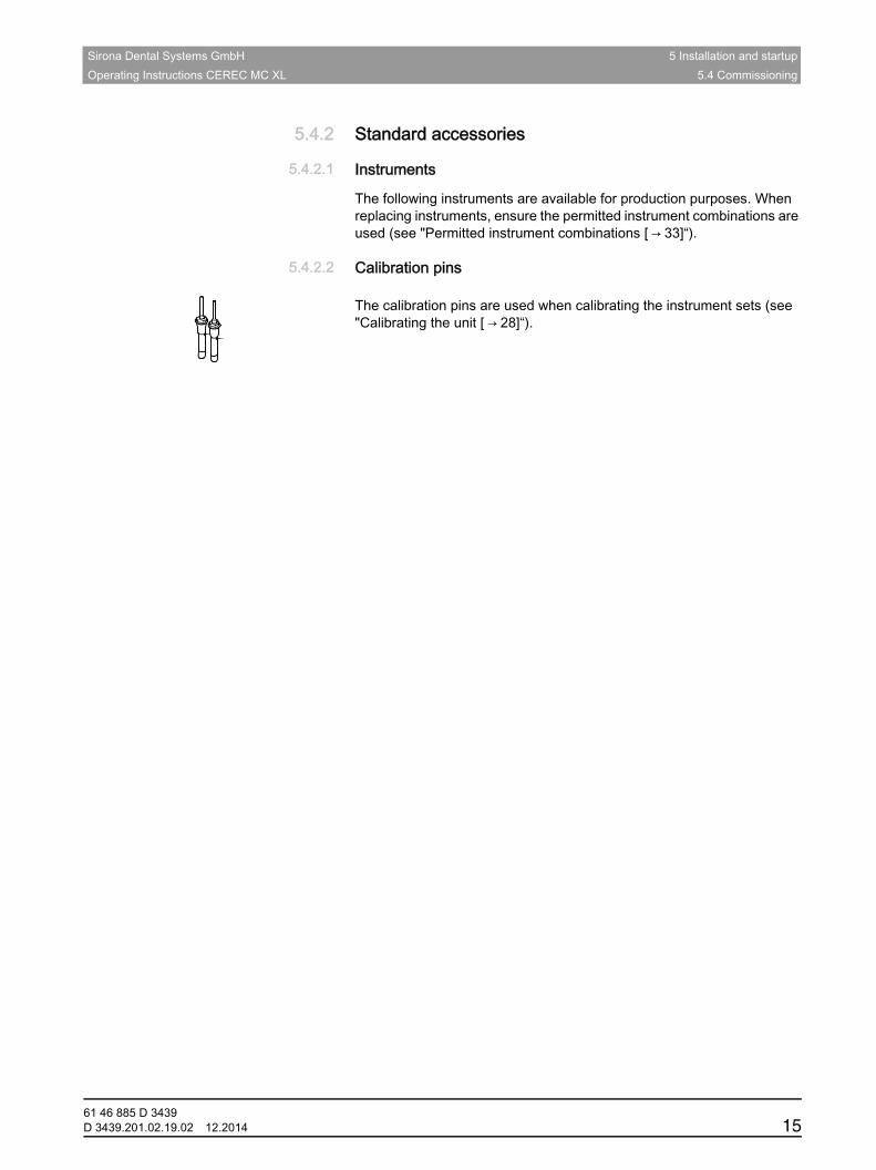
5.4.2.2 Calibration pins
Fragment CEREC MC XL calibration pins The calibration pins are used when calibrating the instrument sets (see "Calibrating the unit [ → 28]“).
61 46 885 D 3439D 3439.201.02.19.02 12.2014 15
5 Installation and startup Sirona Dental Systems GmbH5.4 Commissioning Operating Instructions CEREC MC XL
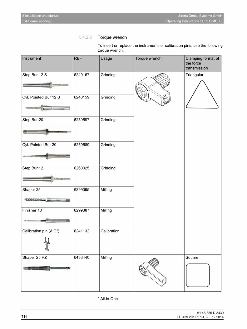
5.4.2.3 Torque wrench
To insert or replace the instruments or calibration pins, use the following torque wrench.Fragment inLab MC XL+CEREC MC XL 300000 torque wrench
* All-in-One
Instrument REF Usage Torque wrench Clamping format of the force transmission
Step Bur 12 S 6240167 Grinding Triangular
Cyl. Pointed Bur 12 S 6240159 Grinding
Step Bur 20 6259597 Grinding
Cyl. Pointed Bur 20 6259589 Grinding
Step Bur 12 6260025 Grinding
Shaper 25 6299395 Milling
Finisher 10 6299387 Milling
Calibration pin (AiO*) 6241132 Calibration
Shaper 25 RZ 6433440 Milling Square
61 46 885 D 343916 D 3439.201.02.19.02 12.2014
Sirona Dental Systems GmbH 5 Installation and startupOperating Instructions CEREC MC XL 5.4 Commissioning
båÖäáëÜ
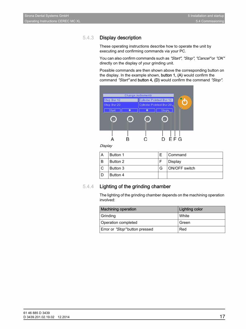
5.4.3 Display descriptionThese operating instructions describe how to operate the unit by executing and confirming commands via your PC.
You can also confirm commands such as "Start", "Stop", "Cancel" or "OK" directly on the display of your grinding unit.
Possible commands are then shown above the corresponding button on the display. In the example shown, button 1, (A) would confirm the command "Start" and button 4, (D) would confirm the command "Stop".
Display
5.4.4 Lighting of the grinding chamberThe lighting of the grinding chamber depends on the machining operation involved:
A Button 1 E CommandB Button 2 F DisplayC Button 3 G ON/OFF switchD Button 4
Machining operation Lighting colorGrinding WhiteOperation completed GreenError or "Stop" button pressed Red
61 46 885 D 3439D 3439.201.02.19.02 12.2014 17
5 Installation and startup Sirona Dental Systems GmbH5.4 Commissioning Operating Instructions CEREC MC XL
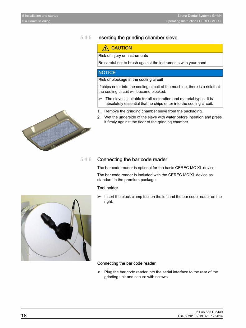
5.4.5 Inserting the grinding chamber sieveCAUTION Grinding instruments
CAUTION CEREC grinding chamber sieve
Fragment: Inserting the grinding chamber sieve1. Remove the grinding chamber sieve from the packaging.2. Wet the underside of the sieve with water before insertion and press
it firmly against the floor of the grinding chamber.
5.4.6 Connecting the bar code readerFragment Notes on CEREC MC XL up to 199000The bar code reader is optional for the basic CEREC MC XL device.
The bar code reader is included with the CEREC MC XL device as standard in the premium package.Gluing on the tool holder
Tool holder
➢ Insert the block clamp tool on the left and the bar code reader on the right.
Connecting the bar code reader
Connecting the bar code reader
➢ Plug the bar code reader into the serial interface to the rear of the grinding unit and secure with screws.
CAUTIONRisk of injury on instruments
Be careful not to brush against the instruments with your hand.
NOTICE Risk of blockage in the cooling circuit
If chips enter into the cooling circuit of the machine, there is a risk that the cooling circuit will become blocked.
➢ The sieve is suitable for all restoration and material types. It is absolutely essential that no chips enter into the cooling circuit.
61 46 885 D 343918 D 3439.201.02.19.02 12.2014
Sirona Dental Systems GmbH 5 Installation and startupOperating Instructions CEREC MC XL 5.4 Commissioning
båÖäáëÜ
5.4.7 Installation
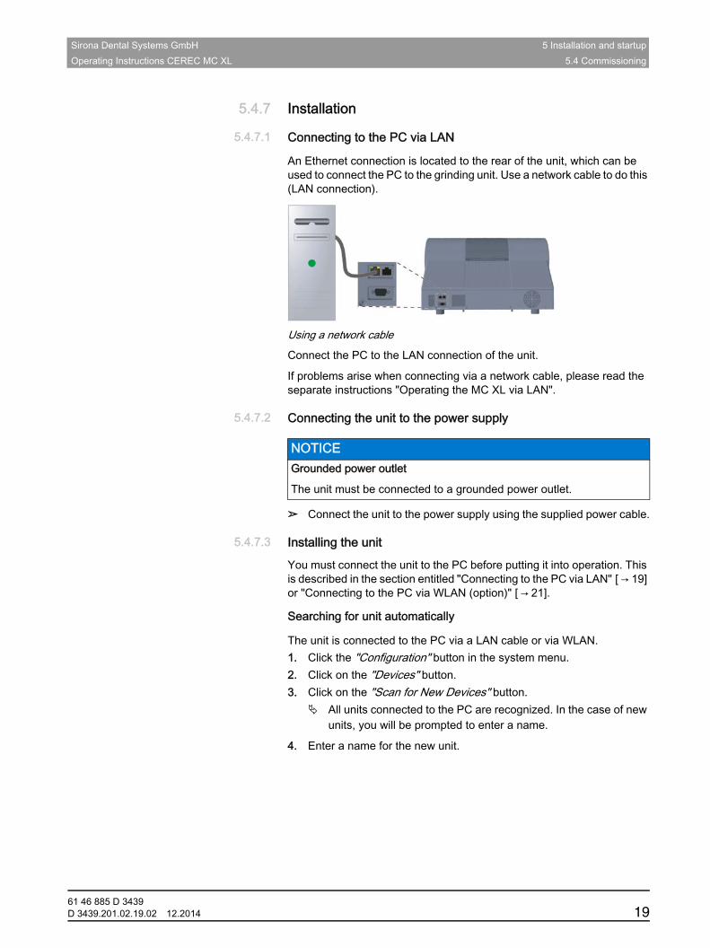
5.4.7.1 Connecting to the PC via LAN
An Ethernet connection is located to the rear of the unit, which can be used to connect the PC to the grinding unit. Use a network cable to do this (LAN connection).
Using a network cable
Connect the PC to the LAN connection of the unit.
If problems arise when connecting via a network cable, please read the separate instructions "Operating the MC XL via LAN".
5.4.7.2 Connecting the unit to the power supply
➢ Connect the unit to the power supply using the supplied power cable.
5.4.7.3 Installing the unitIntroduction worldwideYou must connect the unit to the PC before putting it into operation. This is described in the section entitled "Connecting to the PC via LAN" [ → 19] or "Connecting to the PC via WLAN (option)" [ → 21].Searching for a title automatically
Searching for unit automaticallyPrerequisite worldwideThe unit is connected to the PC via a LAN cable or via WLAN.Searching for a unit automatically, MC XL/MC/MC X1. Click the "Configuration" button in the system menu.2. Click on the "Devices" button.3. Click on the "Scan for New Devices" button.
All units connected to the PC are recognized. In the case of new units, you will be prompted to enter a name.
4. Enter a name for the new unit.Searching for a title manually
NOTICE Grounded power outlet
The unit must be connected to a grounded power outlet.
61 46 885 D 3439D 3439.201.02.19.02 12.2014 19
5 Installation and startup Sirona Dental Systems GmbH5.4 Commissioning Operating Instructions CEREC MC XL
Search for unit manuallyPrerequisite worldwideThe unit is connected to the PC via a LAN cable or via WLAN.Manually search for unit up to 1990001. Click the "Configuration" button in the system menu.2. Click on the "Devices" button.3. Click on the "Add Device (Manual)" button.4. Choose whether the device should be connected via the network or
a serial connection.5. Network: Enter the network address.
Serial: Enter the COM port and the baud rate.6. Click on the "Ok" button.
The software attempts to contact the device.
If the connection fails, check the connection. If necessary, ask a qualified technician.Header Removing the unit
Unit removalRemove the unit✔ If you no longer require a unit (e.g. a unit is replaced), you can remove
it.✔ The unit is operation.1. Click the "Configuration" button in the system menu.2. Click on the "Devices" button.3. Click on the unit that you wish to uninstall.4. Click on the "Delete Device" button.
You will be asked if you would like to remove the unit.
5. Click on the "YES" button. The device is removed.
61 46 885 D 343920 D 3439.201.02.19.02 12.2014
Sirona Dental Systems GmbH 5 Installation and startupOperating Instructions CEREC MC XL 5.4 Commissioning
båÖäáëÜ
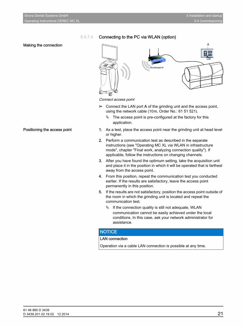
5.4.7.4 Connecting to the PC via WLAN (option)
Making the connection
Connect access point
➢ Connect the LAN port A of the grinding unit and the access point, using the network cable (10m, Order No.: 61 51 521). The access point is pre-configured at the factory for this
application.
Positioning the access point 1. As a test, place the access point near the grinding unit at head level or higher.
2. Perform a communication test as described in the separate instructions (see "Operating MC XL via WLAN in infrastructure mode", chapter "Final work, analyzing connection quality"). If applicable, follow the instructions on changing channels.
3. After you have found the optimum setting, take the acquisition unit and place it in the position in which it will be operated that is farthest away from the access point.
4. From this position, repeat the communication test you conducted earlier. If the results are satisfactory, leave the access point permanently in this position.
5. If the results are not satisfactory, position the access point outside of the room in which the grinding unit is located and repeat the communication test. If the connection quality is still not adequate, WLAN
communication cannot be easily achieved under the local conditions. In this case, ask your network administrator for assistance.
NOTICE LAN connection
Operation via a cable LAN connection is possible at any time.
61 46 885 D 3439D 3439.201.02.19.02 12.2014 21
5 Installation and startup Sirona Dental Systems GmbH5.4 Commissioning Operating Instructions CEREC MC XL
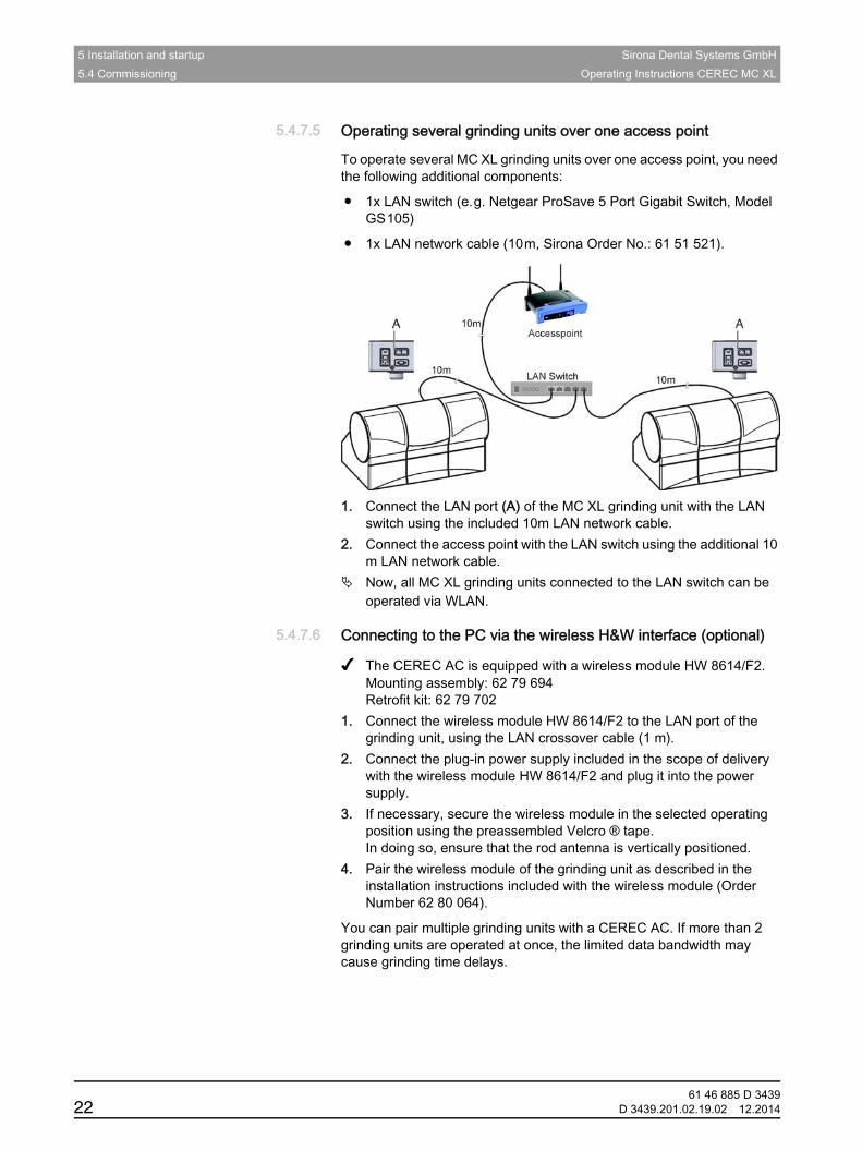
5.4.7.5 Operating several grinding units over one access point
To operate several MC XL grinding units over one access point, you need the following additional components:
● 1x LAN switch (e.g. Netgear ProSave 5 Port Gigabit Switch, Model GS105)
● 1x LAN network cable (10m, Sirona Order No.: 61 51 521).
1. Connect the LAN port (A) of the MC XL grinding unit with the LAN switch using the included 10m LAN network cable.
2. Connect the access point with the LAN switch using the additional 10 m LAN network cable.
Now, all MC XL grinding units connected to the LAN switch can be operated via WLAN.
5.4.7.6 Connecting to the PC via the wireless H&W interface (optional)
✔ The CEREC AC is equipped with a wireless module HW 8614/F2.Mounting assembly: 62 79 694Retrofit kit: 62 79 702
1. Connect the wireless module HW 8614/F2 to the LAN port of the grinding unit, using the LAN crossover cable (1 m).
2. Connect the plug-in power supply included in the scope of delivery with the wireless module HW 8614/F2 and plug it into the power supply.
3. If necessary, secure the wireless module in the selected operating position using the preassembled Velcro ® tape.In doing so, ensure that the rod antenna is vertically positioned.
4. Pair the wireless module of the grinding unit as described in the installation instructions included with the wireless module (Order Number 62 80 064).
You can pair multiple grinding units with a CEREC AC. If more than 2 grinding units are operated at once, the limited data bandwidth may cause grinding time delays.
61 46 885 D 343922 D 3439.201.02.19.02 12.2014
Sirona Dental Systems GmbH 5 Installation and startupOperating Instructions CEREC MC XL 5.4 Commissioning
båÖäáëÜ
5.4.8 Filling the water tankNote on the tank cap opener
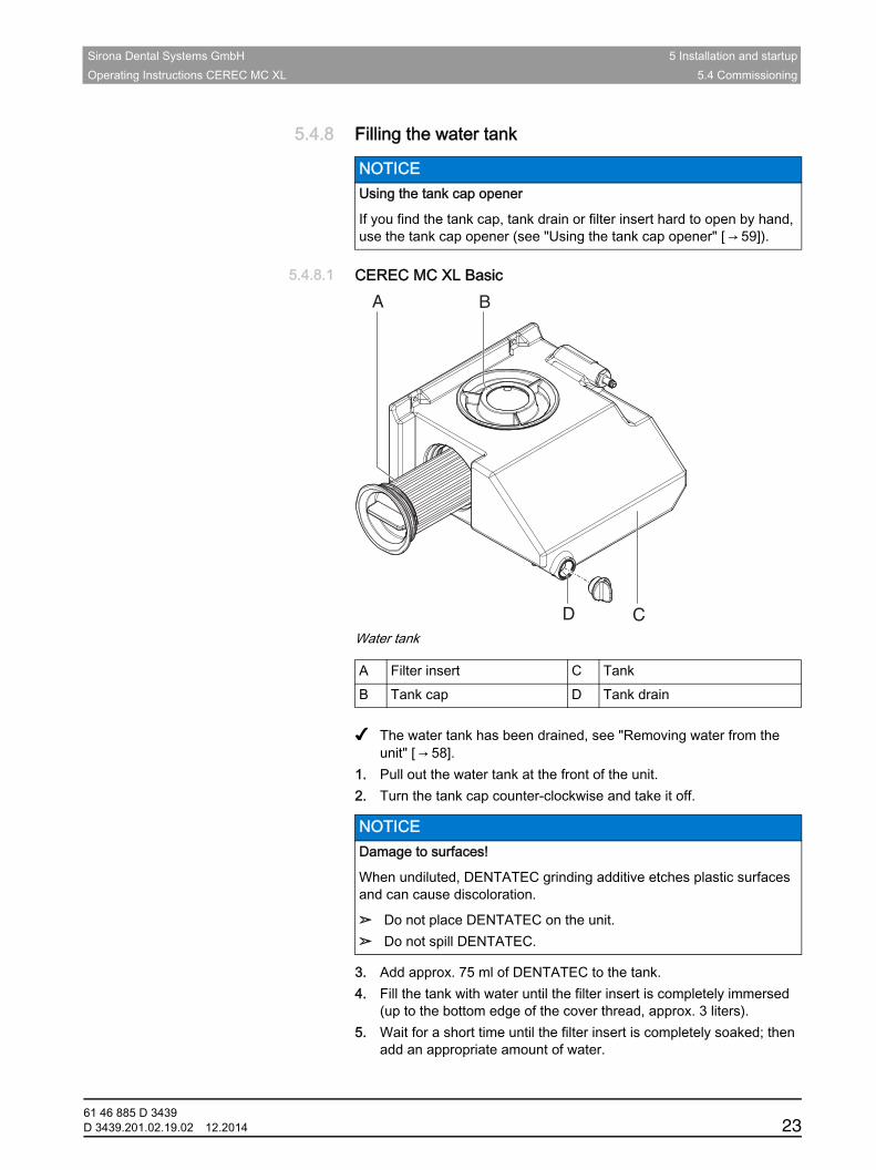
5.4.8.1 CEREC MC XL BasicCEREC water tank
Water tank
Fragment Filling the CEREC water tank✔ The water tank has been drained, see "Removing water from the unit" [ → 58].
1. Pull out the water tank at the front of the unit.2. Turn the tank cap counter-clockwise and take it off.
3. Add approx. 75 ml of DENTATEC to the tank. 4. Fill the tank with water until the filter insert is completely immersed
(up to the bottom edge of the cover thread, approx. 3 liters).5. Wait for a short time until the filter insert is completely soaked; then
add an appropriate amount of water.
NOTICE Using the tank cap opener
If you find the tank cap, tank drain or filter insert hard to open by hand, use the tank cap opener (see "Using the tank cap opener" [ → 59]).
A Filter insert C TankB Tank cap D Tank drain
NOTICE Damage to surfaces!
When undiluted, DENTATEC grinding additive etches plastic surfaces and can cause discoloration.
➢ Do not place DENTATEC on the unit.➢ Do not spill DENTATEC.
A
D
B
C
61 46 885 D 3439D 3439.201.02.19.02 12.2014 23
5 Installation and startup Sirona Dental Systems GmbH5.4 Commissioning Operating Instructions CEREC MC XL
6. Close the water tank by tightening the tank cap clockwise by hand. Do not use the tank cap opener for this.
7. Push the water tank back into the housing.8. Switch the unit on (see Switching the unit ON and OFF [ → 25]).9. Switch the pump on (press the "Pump" button) to fill the water circuit.10. Fill the water tank up again until the filter insert is completely
immersed (up to the bottom edge of the cap thread).
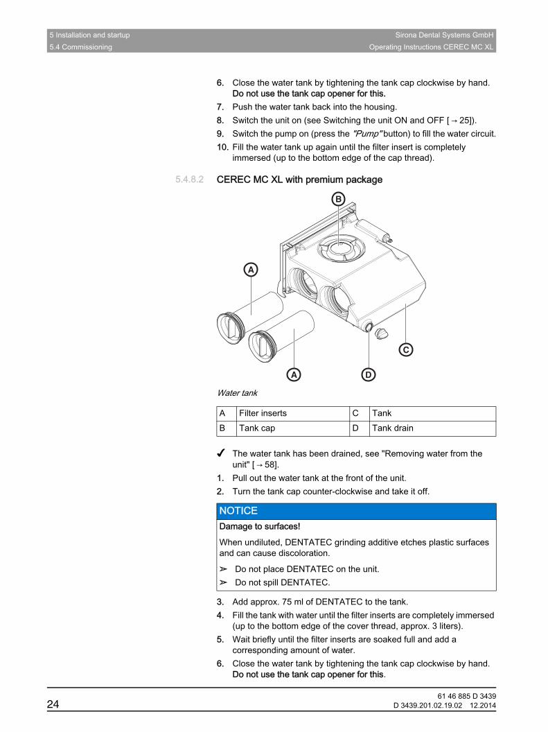
5.4.8.2 CEREC MC XL with premium packageinLab water tank
Water tank
Fragment Filling the inLab water tank✔ The water tank has been drained, see "Removing water from the unit" [ → 58].
1. Pull out the water tank at the front of the unit.2. Turn the tank cap counter-clockwise and take it off.
3. Add approx. 75 ml of DENTATEC to the tank. 4. Fill the tank with water until the filter inserts are completely immersed
(up to the bottom edge of the cover thread, approx. 3 liters).5. Wait briefly until the filter inserts are soaked full and add a
corresponding amount of water.6. Close the water tank by tightening the tank cap clockwise by hand.
Do not use the tank cap opener for this.
A Filter inserts C TankB Tank cap D Tank drain
NOTICE Damage to surfaces!
When undiluted, DENTATEC grinding additive etches plastic surfaces and can cause discoloration.
➢ Do not place DENTATEC on the unit.➢ Do not spill DENTATEC.
A
A D
C
B
61 46 885 D 343924 D 3439.201.02.19.02 12.2014
Sirona Dental Systems GmbH 5 Installation and startupOperating Instructions CEREC MC XL 5.4 Commissioning
båÖäáëÜ
7. Push the water tank back into the housing.8. Switch the unit on (see Switching the unit ON and OFF [ → 25]).9. Switch the pump on (press the "Pump" button) to fill the water circuit.10. Fill the water tank up again until the filter inserts are completely
immersed (up to the bottom edge of the cover thread).
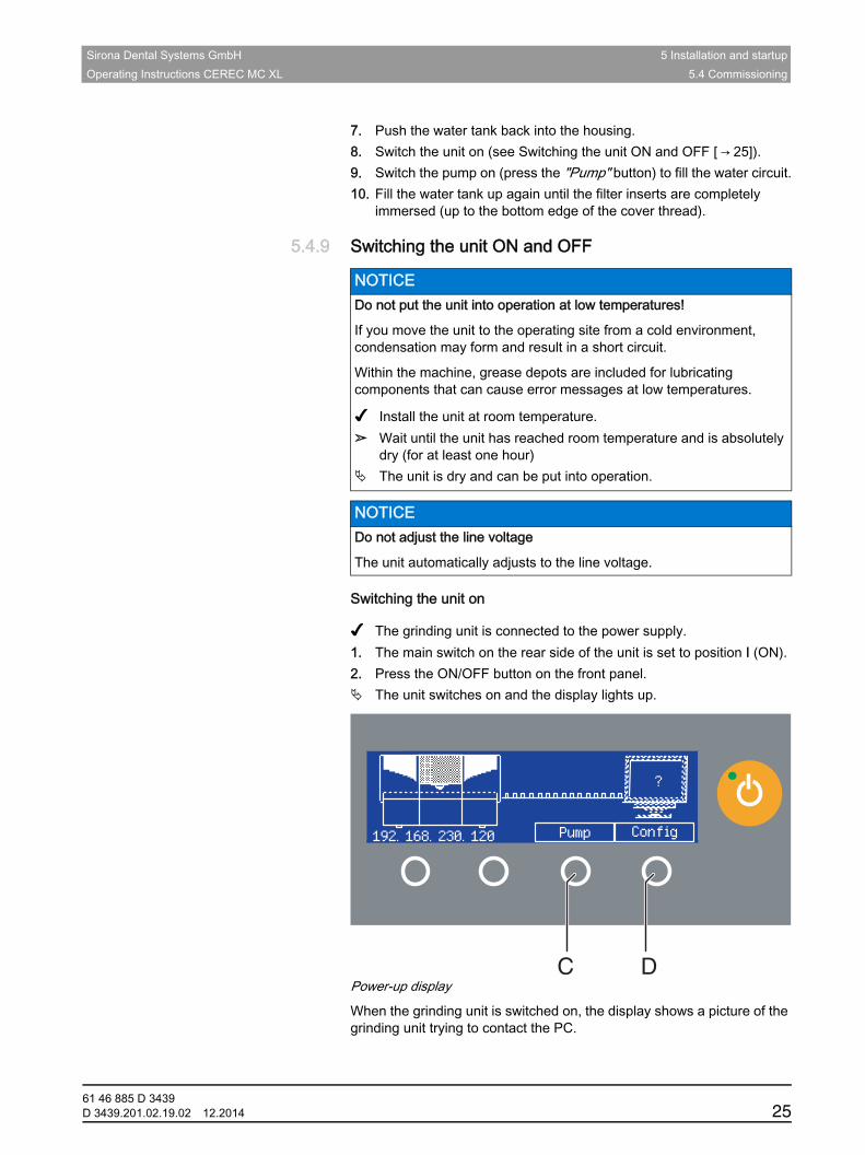
5.4.9 Switching the unit ON and OFFNote on condensate
Line voltage
Switching the unit on
✔ The grinding unit is connected to the power supply.1. The main switch on the rear side of the unit is set to position I (ON).2. Press the ON/OFF button on the front panel. The unit switches on and the display lights up.
Power-up display
When the grinding unit is switched on, the display shows a picture of the grinding unit trying to contact the PC.
NOTICE Do not put the unit into operation at low temperatures!
If you move the unit to the operating site from a cold environment, condensation may form and result in a short circuit.
Within the machine, grease depots are included for lubricating components that can cause error messages at low temperatures.
✔ Install the unit at room temperature.➢ Wait until the unit has reached room temperature and is absolutely
dry (for at least one hour) The unit is dry and can be put into operation.
NOTICE Do not adjust the line voltage
The unit automatically adjusts to the line voltage.
C D
192. 168. 230. 120 Pump Config
?
61 46 885 D 3439D 3439.201.02.19.02 12.2014 25
5 Installation and startup Sirona Dental Systems GmbH5.5 Repacking Operating Instructions CEREC MC XL
You can start or stop the water pump by pressing the "Pump" button (C). This enables you to drain the water circuit without connecting to the PC (e.g. prior to transport) or fill the water circuit during startup.
You can call up the IP address by pressing the "Config" button (D). You can configure the grinding unit in the network with this address.
Switching the unit off
✔ The unit has finished the machining operation.➢ Briefly press the ON/OFF button on the front panel. When you let go of the button, the unit switches off.
5.5 RepackingFragment Repacking CEREC MC XL
✔ The water tank is empty. ✔ The main switch on the back side of the unit is set to the 0 (OFF)
position.1. Disconnect the power cable and the connecting cable from the back
side of the unit and stow them away.2. Stow away the calibration tools in the drawer.3. Check the unit for completeness according to the scope of supply!4. Pack the unit securely.
5.6 Scope of supplyThe detailed scope of supply is specified in the document "Checklist CEREC MC XL".
5.7 StorageFragment Repacking CEREC MC XL
Store the unit in a closed and dry room at a temperature of -10°C to 50°C for a maximum period of 12 months.
NOTICE Repack only drained units!
Drain the unit! See "Removing water from the unit [ → 58]“.
NOTICE Repack only drained units!
Drain the unit! See "Removing water from the unit [ → 58]“.
61 46 885 D 343926 D 3439.201.02.19.02 12.2014
Sirona Dental Systems GmbH 6 OperationOperating Instructions CEREC MC XL 6.1 Configuration (CEREC MC XL)
båÖäáëÜ
6 Operation
6.1 Configuration (CEREC MC XL)DescriptionIn the "Devices" area of the CEREC SW software, various settings can be subsequently modified.
1. Click the "Configuration" button in the system menu.2. Click on the "Devices" button.3. Click on the unit that you wish to configure.Title: De-activating the CEREC bur set
De-activating an instrument set (only for grinding units with 4 motors)Description of deactivation of the Premium Package bur setYou may need to deactivate an instrument set, e.g. unless it is possible to replace a defective instrument or in case a grinding motor is defective or cannot be calibrated.
In all of these cases, you can deactivate sets 1 and 2 separately. A deactivated set will simply be ignored during production, calibration etc.
➢ You can deactivate an instrument set by removing the check mark in front of the instrument set in the software or by deactivating the instrument set on the touch display under "Edit Device Settings".
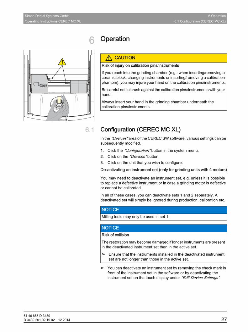
CAUTIONRisk of injury on calibration pins/instruments
If you reach into the grinding chamber (e.g.: when inserting/removing a ceramic block, changing instruments or inserting/removing a calibration phantom), you may injure your hand on the calibration pins/instruments.
Be careful not to brush against the calibration pins/instruments with your hand.
Always insert your hand in the grinding chamber underneath the calibration pins/instruments.
NOTICE Milling tools may only be used in set 1.
NOTICE Risk of collision
The restoration may become damaged if longer instruments are present in the deactivated instrument set than in the active set.
➢ Ensure that the instruments installed in the deactivated instrument set are not longer than those in the active set.
61 46 885 D 3439D 3439.201.02.19.02 12.2014 27
6 Operation Sirona Dental Systems GmbH6.2 Calibrating the unit Operating Instructions CEREC MC XL
6.2 Calibrating the unitCalibration tools
Calibrating the inLab+CEREC SW4 grinding unit
Unit calibrated ex works
The unit is calibrated at the factory. No additional calibration is required during initial startup. Proceed as described below when performing a subsequent calibration.
Preparing a calibration
1. Take the calibration pins and calibration phantom out of the drawer of the unit.
2. In the software, navigate to the system menu, and click on the "Configuration" button.
3. Click on the "Devices" button.4. Click on the unit that you wish to calibrate.5. Click on the "Calibrate" step.
If two instrument sets are set:A dialog box then opens where you can select the instrument set to be calibrated or the two instrument sets to be calibrated consecutively. The date of the last calibration is also displayed.
6. If necessary, select the desired instrument set.You can also select the desired instrument set on the grinding unit (up/down arrow).
7. Click on the "Start" button. The grinding unit then moves into position to insert the calibration
tools.A dialog box prompts you to insert the calibration pins and the calibration phantom and to close the grinding chamber door again.
NOTICE Use only the supplied calibration tools
Use only the supplied calibration pins and the corresponding calibration phantom when calibrating the grinding unit.
NOTICE Faulty production result
If the unit is not calibrated, the production result may be faulty.
61 46 885 D 343928 D 3439.201.02.19.02 12.2014
Sirona Dental Systems GmbH 6 OperationOperating Instructions CEREC MC XL 6.2 Calibrating the unit
båÖäáëÜ
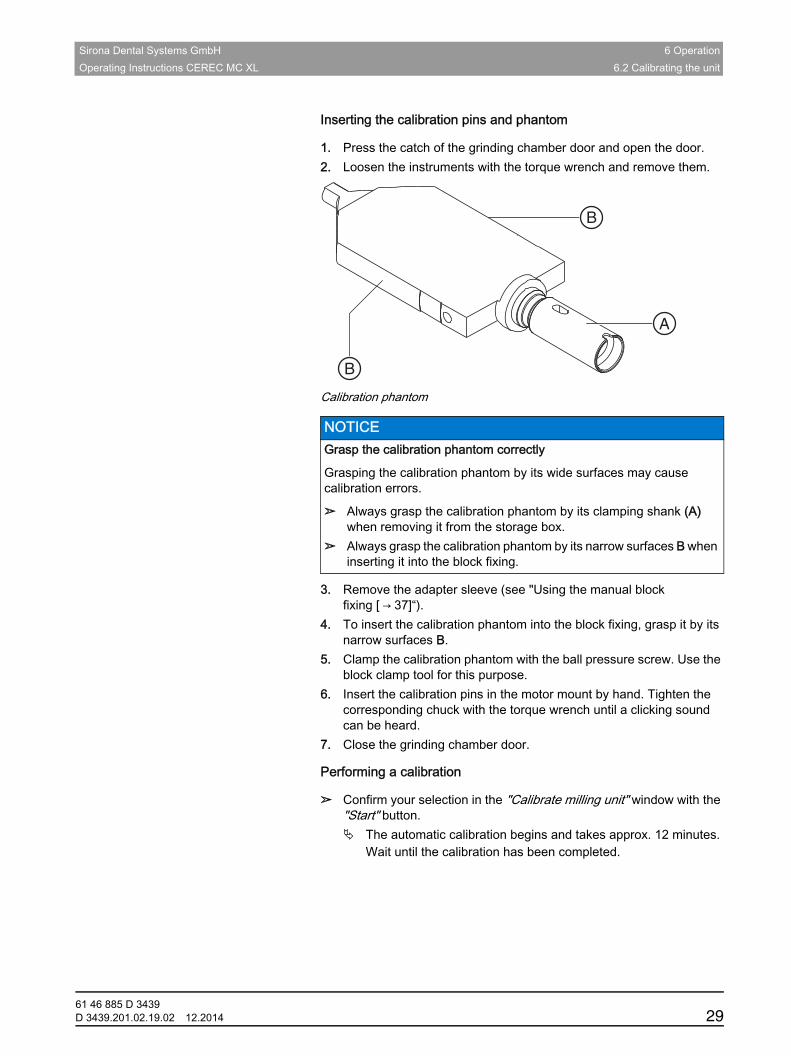
Inserting the calibration pins and phantom
1. Press the catch of the grinding chamber door and open the door.2. Loosen the instruments with the torque wrench and remove them.
Calibration phantom
3. Remove the adapter sleeve (see "Using the manual block fixing [ → 37]“).
4. To insert the calibration phantom into the block fixing, grasp it by its narrow surfaces B.
5. Clamp the calibration phantom with the ball pressure screw. Use the block clamp tool for this purpose.
6. Insert the calibration pins in the motor mount by hand. Tighten the corresponding chuck with the torque wrench until a clicking sound can be heard.
7. Close the grinding chamber door.
Performing a calibration
➢ Confirm your selection in the "Calibrate milling unit" window with the "Start" button. The automatic calibration begins and takes approx. 12 minutes.
Wait until the calibration has been completed.
NOTICE Grasp the calibration phantom correctly
Grasping the calibration phantom by its wide surfaces may cause calibration errors.
➢ Always grasp the calibration phantom by its clamping shank (A) when removing it from the storage box.
➢ Always grasp the calibration phantom by its narrow surfaces B when inserting it into the block fixing.
A
B
B
61 46 885 D 3439D 3439.201.02.19.02 12.2014 29
6 Operation Sirona Dental Systems GmbH6.2 Calibrating the unit Operating Instructions CEREC MC XL
Inserting instruments
1. Open the grinding chamber door following calibration.2. Loosen the calibration pins with the torque wrench and remove them.3. Loosen the ball pressure screw.4. Remove the calibration phantom by grasping it by its narrow surfaces
(B).
5. Insert the instruments in the motor mount by hand. Tighten the corresponding chuck with the torque wrench until a clicking sound can be heard.
6. Close the grinding chamber door. The dialog box for selecting the instruments then appears.
7. Select the inserted instruments and confirm by clicking the "Start" button in the window. The motor mounts move to their starting positions.
The "Calibration succeeded" dialog box appears.
Exiting the calibration
1. Click on the "OK" button.2. Click on the step "Exit Configuration".
NOTICE Store the calibration tools in a safe place
Store the calibration pins and the calibration body in a safe place (e.g. in a storage box in the unit drawer).
61 46 885 D 343930 D 3439.201.02.19.02 12.2014
Sirona Dental Systems GmbH 6 OperationOperating Instructions CEREC MC XL 6.3 Production process
båÖäáëÜ
6.3 Production process
6.3.1 Process typesVarious process types are available for production purposes. These vary in terms of the type of materials to be processed and the instruments to be used.
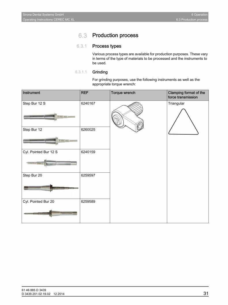
6.3.1.1 Grinding
For grinding purposes, use the following instruments as well as the appropriate torque wrench:
Instrument REF Torque wrench Clamping format of the force transmission
Step Bur 12 S 6240167 Triangular
Step Bur 12 6260025
Cyl. Pointed Bur 12 S 6240159
Step Bur 20 6259597
Cyl. Pointed Bur 20 6259589
61 46 885 D 3439D 3439.201.02.19.02 12.2014 31
6 Operation Sirona Dental Systems GmbH6.3 Production process Operating Instructions CEREC MC XL
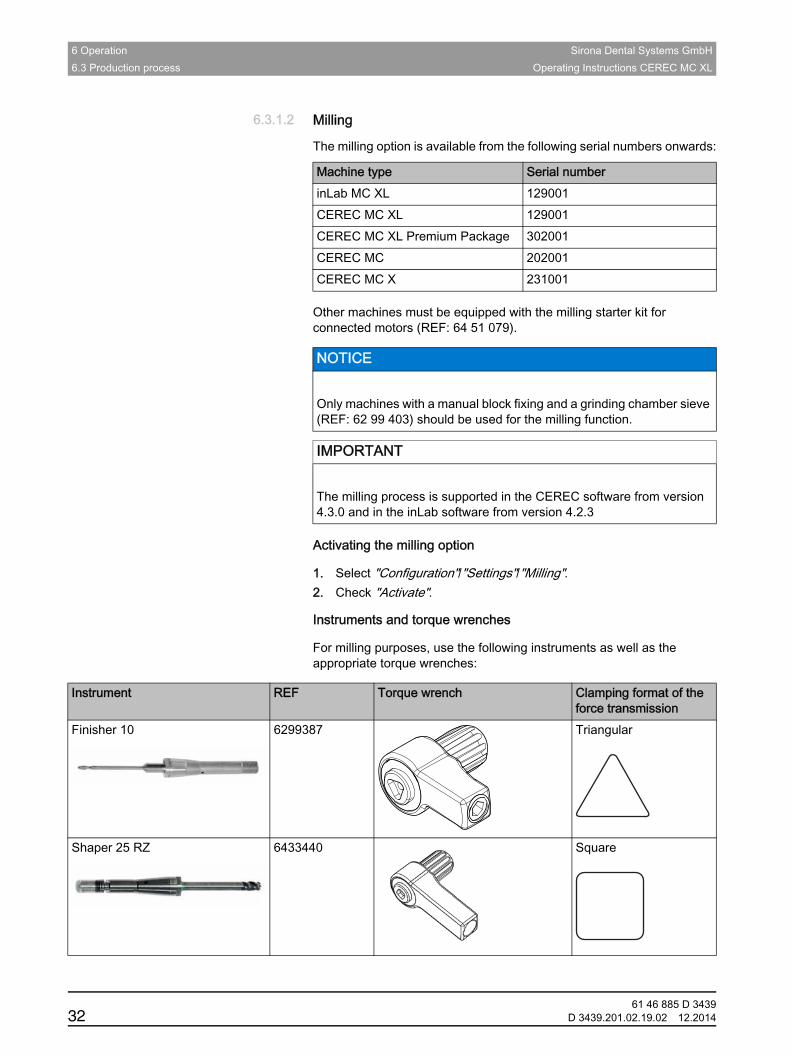
6.3.1.2 Milling
The milling option is available from the following serial numbers onwards:Fragment table CEREC MC XL 199000 milling
Other machines must be equipped with the milling starter kit for connected motors (REF: 64 51 079).
Fragment Software version
Activating the milling option
1. Select "Configuration"/"Settings"/"Milling".2. Check "Activate".
Instruments and torque wrenches
For milling purposes, use the following instruments as well as the appropriate torque wrenches:
Machine type Serial numberinLab MC XL 129001CEREC MC XL 129001CEREC MC XL Premium Package 302001CEREC MC 202001CEREC MC X 231001
NOTICE
Only machines with a manual block fixing and a grinding chamber sieve (REF: 62 99 403) should be used for the milling function.
IMPORTANT
The milling process is supported in the CEREC software from version 4.3.0 and in the inLab software from version 4.2.3
Instrument REF Torque wrench Clamping format of the force transmission
Finisher 10 6299387 Triangular
Shaper 25 RZ 6433440 Square
61 46 885 D 343932 D 3439.201.02.19.02 12.2014
Sirona Dental Systems GmbH 6 OperationOperating Instructions CEREC MC XL 6.3 Production process
båÖäáëÜ
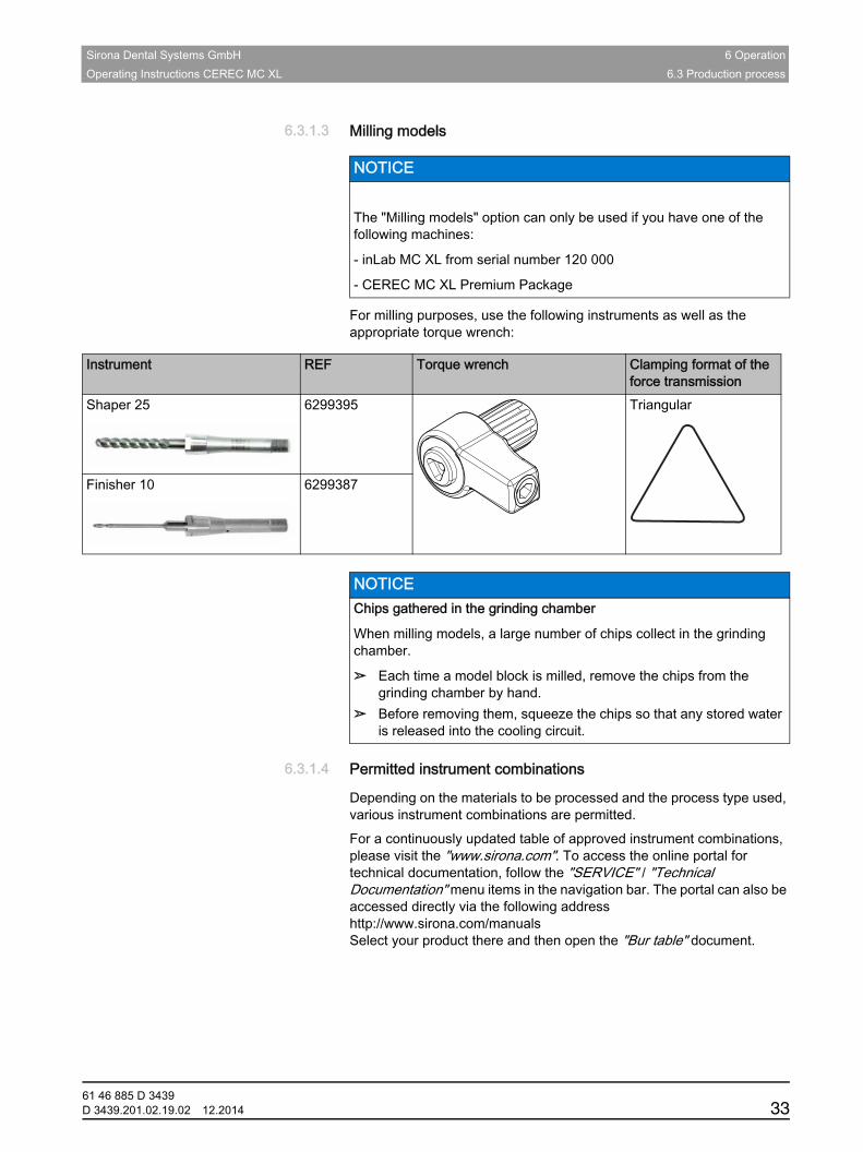
6.3.1.3 Milling models
For milling purposes, use the following instruments as well as the appropriate torque wrench:
Removing chips
6.3.1.4 Permitted instrument combinations
Depending on the materials to be processed and the process type used, various instrument combinations are permitted.Fragment Instrument combinationsFor a continuously updated table of approved instrument combinations, please visit the "www.sirona.com". To access the online portal for technical documentation, follow the "SERVICE" / "Technical Documentation" menu items in the navigation bar. The portal can also be accessed directly via the following address http://www.sirona.com/manuals Select your product there and then open the "Bur table" document.
NOTICE
The "Milling models" option can only be used if you have one of the following machines:
- inLab MC XL from serial number 120 000
- CEREC MC XL Premium Package
Instrument REF Torque wrench Clamping format of the force transmission
Shaper 25 6299395 Triangular
Finisher 10 6299387
NOTICE Chips gathered in the grinding chamber
When milling models, a large number of chips collect in the grinding chamber.
➢ Each time a model block is milled, remove the chips from the grinding chamber by hand.
➢ Before removing them, squeeze the chips so that any stored water is released into the cooling circuit.
61 46 885 D 3439D 3439.201.02.19.02 12.2014 33
6 Operation Sirona Dental Systems GmbH6.3 Production process Operating Instructions CEREC MC XL
6.3.2 PreparationsFragment Preparations✔ Download or design a restoration (see operator's manual).✔ When the "Milling" option is activated, in the "Select Material" material
selection step, you can choose between the "Grinding" and "Milling" manufacturing processes for plastic and zirconium oxide materials.
✔ You are in the "MILL" phase and have selected the grinding unit, tested the settings, and positioned the restoration in the block.
➢ Click on the "Start Milling" step. The grinding unit then moves to the insertion position.
6.3.3 Starting the production processFragment Starting the production process✔ The instrument sets are equipped with the required instrument
combinations for the production process.1. Depending on the configuration, you will be prompted to enter the bar
code (see also "Entering the bar code“).2. Press the catch of the grinding chamber door and open the door.
3. Place the selected ceramic block in the block fixing.4. Clamp the ceramic block with the ball pressure screw. Use the block
clamp tool for this purpose (see also "Using the manual block fixing [ → 37]“).
5. Close the grinding chamber door and confirm the procedure by clicking "Start". The estimated time required for the production process will then
appear in a message window.
NOTICE Error message during touch process!
Always be sure to insert the ceramic block that you selected for the restoration. Otherwise an error message will be displayed during the touch process.
NOTICE Aborting the production process
You can abort the production process at any time by pressing the "Stop" button.
61 46 885 D 343934 D 3439.201.02.19.02 12.2014
Sirona Dental Systems GmbH 6 OperationOperating Instructions CEREC MC XL 6.3 Production process
båÖäáëÜ
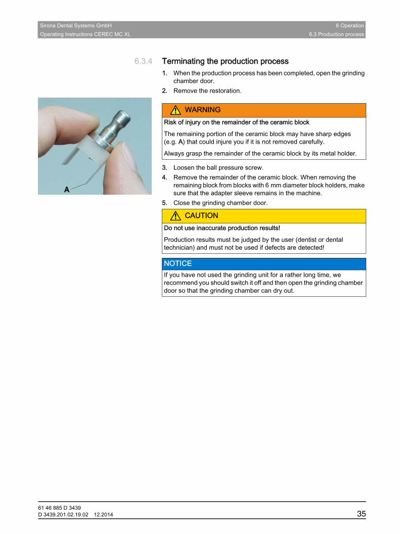
6.3.4 Terminating the production processFragment Terminating the production process1. When the production process has been completed, open the grinding
chamber door.2. Remove the restoration.
3. Loosen the ball pressure screw.4. Remove the remainder of the ceramic block. When removing the
remaining block from blocks with 6 mm diameter block holders, make sure that the adapter sleeve remains in the machine.
5. Close the grinding chamber door.Defective grinding results
Open the grinding chamber door
WARNINGRisk of injury on the remainder of the ceramic block
The remaining portion of the ceramic block may have sharp edges (e.g. A) that could injure you if it is not removed carefully.
Always grasp the remainder of the ceramic block by its metal holder.
CAUTIONDo not use inaccurate production results!
Production results must be judged by the user (dentist or dental technician) and must not be used if defects are detected!
NOTICE If you have not used the grinding unit for a rather long time, we recommend you should switch it off and then open the grinding chamber door so that the grinding chamber can dry out.
61 46 885 D 3439D 3439.201.02.19.02 12.2014 35
6 Operation Sirona Dental Systems GmbH6.4 Entering the bar code Operating Instructions CEREC MC XL
6.3.5 Information regarding the quality seal (CEREC MC XL with premium package)Fragment Seal of approvalProper selection and processing of the material are decisive for the long-term clinical success of the restoration, especially in the case of zirconia. However, different types of zirconia require individually matched machine parameters. This is the reason why you can and must select different types of zirconia in the inLab software. These machine parameters are coordinated between Sirona and its material partners in complex development processes. In addition to the desired fit and surface quality, they also guarantee a maximum degree of material and equipment safety. The consistently high quality of the production results and the fit can only be guaranteed and damage to the production machines can only be excluded if certified materials are used.
6.4 Entering the bar codeBar code reader active
Barcode Reader active
If you have activated the option "Barcode Reader" in the system configuration dialog (e.g. for inCoris ZI), you must read-in both bar codes with the bar code reader. To do this, hold the bar code reader tilted to a slight angle and move it over both of the bar codes on the block continuously and evenly.
If the reading process fails, you can read-in the bar code once again by pressing "Retry" (button 1 on the unit display). Alternatively, you also can enter the substitute code (8-digit character string, e.g. *1234XYZ) on the PC manually.No bar code reader available
No bar code reader available
➢ Enter the substitute code (8-digit character string, e.g. *1234XYZ) on the PC manually.
NOTICE Block without seal of approval
If a block is found without a seal of approval during the production process (milling or grinding), the following message appears: „No quality label was recognized on the block. The grinding and milling processes as well as the instruments are specially verified for certified materials. Certified materials can be identified by the engraved "inLab" lettering on the block. The use of zirconium oxide materials without quality label can lead to inferior results as well as increased wear on the device and instruments. Do you still wish to start the manufacturing process?“
61 46 885 D 343936 D 3439.201.02.19.02 12.2014
Sirona Dental Systems GmbH 6 OperationOperating Instructions CEREC MC XL 6.5 Using the manual block fixing
båÖäáëÜ
6.5 Using the manual block fixingStore the block clamp tool in the corresponding holder (see also "Gluing on the tool holder" [ → 18]).You can attach the holder to a suitable location with the adhesive pad. Clean and degrease the contact surface beforehand.NOTE: Wear to the ball pressure screw
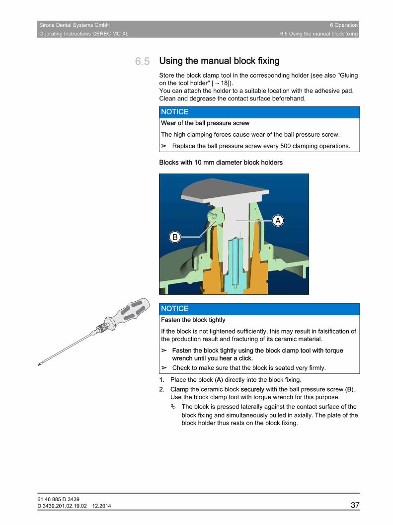
Blocks with 10 mm diameter block holders
Fastening the block
Instructions for 10 mm diameter1. Place the block (A) directly into the block fixing.2. Clamp the ceramic block securely with the ball pressure screw (B).
Use the block clamp tool with torque wrench for this purpose. The block is pressed laterally against the contact surface of the
block fixing and simultaneously pulled in axially. The plate of the block holder thus rests on the block fixing.
NOTICE Wear of the ball pressure screw
The high clamping forces cause wear of the ball pressure screw.
➢ Replace the ball pressure screw every 500 clamping operations.
NOTICE Fasten the block tightly
If the block is not tightened sufficiently, this may result in falsification of the production result and fracturing of its ceramic material.
➢ Fasten the block tightly using the block clamp tool with torque wrench until you hear a click.
➢ Check to make sure that the block is seated very firmly.
61 46 885 D 3439D 3439.201.02.19.02 12.2014 37
6 Operation Sirona Dental Systems GmbH6.5 Using the manual block fixing Operating Instructions CEREC MC XL
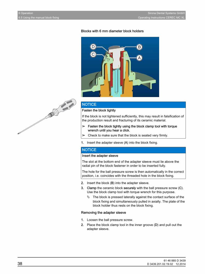
Blocks with 6 mm diameter block holders
Fastening the block
1. Insert the adapter sleeve (A) into the block fixing.
2. Insert the block (B) into the adapter sleeve.3. Clamp the ceramic block securely with the ball pressure screw (C).
Use the block clamp tool with torque wrench for this purpose. The block is pressed laterally against the contact surface of the
block fixing and simultaneously pulled in axially. The plate of the block holder thus rests on the block fixing.
Removing the adapter sleeve
1. Loosen the ball pressure screw.2. Place the block clamp tool in the inner groove (D) and pull out the
adapter sleeve.
NOTICE Fasten the block tightly
If the block is not tightened sufficiently, this may result in falsification of the production result and fracturing of its ceramic material.
➢ Fasten the block tightly using the block clamp tool with torque wrench until you hear a click.
➢ Check to make sure that the block is seated very firmly.
NOTICE Insert the adapter sleeve
The slot at the bottom end of the adapter sleeve must lie above the radial pin of the block fastener in order to be inserted fully.
The hole for the ball pressure screw is then automatically in the correct position, i.e. coincides with the threaded hole in the block fixing.
61 46 885 D 343938 D 3439.201.02.19.02 12.2014
Sirona Dental Systems GmbH 7 ServiceOperating Instructions CEREC MC XL
båÖäáëÜ
7 ServiceMaintenance, 1st note
Maintenance, 2nd note
Maintenance, 3rd note
CEREC Cleaning intervals
Cleaning intervals CEREC MC XL premium package
NOTICE Observe country-specific Regulations!
Some countries have legal regulations which require regular safety inspections of electrical devices or systems by the operator.
NOTICE Perform maintenance regularly!
Have maintenance performed on your unit annually by trained technical personnel / a service engineer.
NOTICE Observe error messages
You must observe error messages shown on the display on in the software. If the error message does not disappear even after you have performed the prompted action, contact your service engineer.
NOTICE Machine care (CEREC MC XL Basic)
Interval: Once a month
➢ Clean the block chuck and block clamping nut according to the cleaning set instructions (REF 61 77 161).
➢ Clean the chucks of the grinding instruments according to the cleaning set instructions (REF 61 77 161).
➢ If the jets of water do not strike the grinding instruments, carefully remove any foreign particles from the water nozzles with a probe.
NOTICE Machine care (CEREC MC XL with premium package)
Interval: Once a week or after every 4th water change
➢ Change the filter (see Changing the filter [ → 52])➢ Clean the manual block fixing according to the cleaning set
instructions (REF 61 77 161).➢ Clean the clamping cones and chucks of the grinding instruments
according to the cleaning set instructions (REF 61 77 161).➢ If the jets of water do not strike the grinding instruments, carefully
remove any foreign particles from the water nozzles with a probe.
61 46 885 D 3439D 3439.201.02.19.02 12.2014 39
7 Service Sirona Dental Systems GmbH7.1 Changing the water Operating Instructions CEREC MC XL
Removing chips
Fragment Do not confuse CEREC MC XL
Note on the tank cap opener
NOTE: Wear to the ball pressure screw
7.1 Changing the water
7.1.1 General informationFragment: Ceramic content
When the water is due to be changed, a message window appears on your monitor to remind you that it is time to change the water.
NOTICE Chips gathered in the grinding chamber
When milling models, a large number of chips collect in the grinding chamber.
➢ Each time a model block is milled, remove the chips from the grinding chamber by hand.
➢ Before removing them, squeeze the chips so that any stored water is released into the cooling circuit.
NOTICE Do not confuse the block screw with the ball pressure screw
When operating a CEREC 3 grinding unit and a CEREC MC XL grinding unit in the same room, be careful not to confuse the block screw of the CEREC 3 with the ball pressure screw of the CEREC MC XL.
NOTICE Using the tank cap opener
If you find the tank cap, tank drain or filter insert hard to open by hand, use the tank cap opener (see "Using the tank cap opener" [ → 59]).
NOTICE Wear of the ball pressure screw
The high clamping forces cause wear of the ball pressure screw.
➢ Replace the ball pressure screw every 500 clamping operations.
NOTICE Damage to the pump and grinding drives!
An excessively high ceramic content in the cooling water will damage the pump and grinding drives.
Change the water regularly!
61 46 885 D 343940 D 3439.201.02.19.02 12.2014
Sirona Dental Systems GmbH 7 ServiceOperating Instructions CEREC MC XL 7.1 Changing the water
båÖäáëÜ
Preventing odors
All grinding additives contain a biologically degradable preservative. Despite this, however, odors may still develop under unfavorable conditions.
Observe the following:
● Change the water at least once a week.
● With ambient temperatures above 25°C, change the water every 2 to 3 days to prevent foul odors.
● Drain the tank if you do not intend to operate the unit for more than one week.
● Clean the tank if the odors recur.
● Add DENTATEC grinding additive and fill the tank up to the brim with water. Let it stand for at least 24 hours and then rinse it out thoroughly with water once again.
NOTICE Damage to surfaces!
When undiluted, DENTATEC grinding additive etches plastic surfaces and can cause discoloration.
➢ Do not place DENTATEC on the unit.➢ Do not spill DENTATEC.
NOTICE Permissible grinding additive
Use only DENTATEC as a grinding additive.
61 46 885 D 3439D 3439.201.02.19.02 12.2014 41
7 Service Sirona Dental Systems GmbH7.1 Changing the water Operating Instructions CEREC MC XL
7.1.2 Changing the water (CEREC MC XL Basic)Fragment Change water (CEREC MC XL Basic)To change the water, proceed as follows:
✔ The unit is switched on.✔ No machining process is running.1. Pull out the water tank at the front of the unit.2. Open the drain opening.3. Drain the water tank.4. Turn the tank cap counter-clockwise and take it off. If you find the tank
cap hard to open by hand, use the tank cap opener (see "Opening the tank cap" [ → 59]).
5. Unscrew the side cap.6. Remove the filter insert from the tank and clean the filter thoroughly
under running water.7. Rinse the water tank.8. Insert the cleaned filter with its cap into the unit and screw it tight.9. Close the drain opening.
10. Add approx. 75 ml of DENTATEC to the tank. 11. Fill the tank with water until the filter insert is completely immersed
(up to the bottom edge of the cover thread, approx. 3 liters).12. Wait for a short time until the filter insert is completely soaked; then
add an appropriate amount of water.13. Close the water tank by tightening the tank cap clockwise by hand.
Do not use the tank cap opener for this.14. Push the water tank back into the housing.
NOTICE Foaming not permissible!
If any cleaning agents are used, this will create foam, which is not permitted.
Do not use any cleaning agents.
61 46 885 D 343942 D 3439.201.02.19.02 12.2014
Sirona Dental Systems GmbH 7 ServiceOperating Instructions CEREC MC XL 7.1 Changing the water
båÖäáëÜ
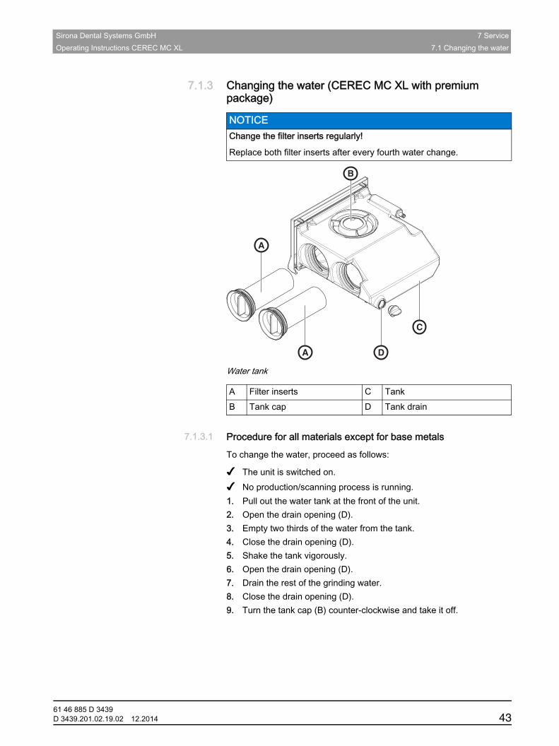
7.1.3 Changing the water (CEREC MC XL with premium package)Fragment Change the filter inserts regularly
inLab water tank
Water tank
7.1.3.1 Procedure for all materials except for base metalsFragment Changing the water inLab + premium packageTo change the water, proceed as follows:
✔ The unit is switched on.✔ No production/scanning process is running.1. Pull out the water tank at the front of the unit.2. Open the drain opening (D).3. Empty two thirds of the water from the tank.4. Close the drain opening (D).5. Shake the tank vigorously.6. Open the drain opening (D).7. Drain the rest of the grinding water.8. Close the drain opening (D).9. Turn the tank cap (B) counter-clockwise and take it off.
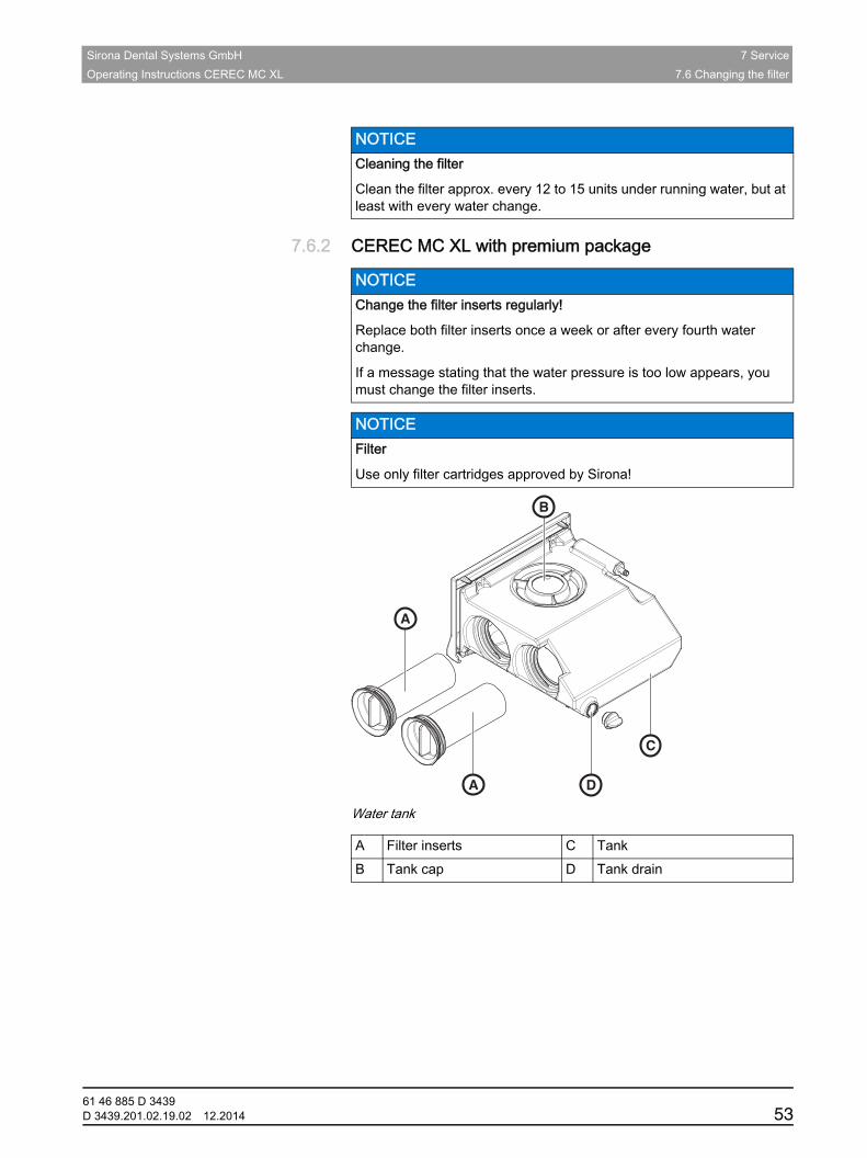
NOTICE Change the filter inserts regularly!
Replace both filter inserts after every fourth water change.
A Filter inserts C TankB Tank cap D Tank drain
A
A D
C
B
61 46 885 D 3439D 3439.201.02.19.02 12.2014 43
7 Service Sirona Dental Systems GmbH7.1 Changing the water Operating Instructions CEREC MC XL
10. Add approx. 75 ml of DENTATEC to the tank. 11. Fill the tank with water until the filter inserts (A) are completely
immersed (up to the bottom edge of the cover thread, approx. 3 liters).
12. Wait briefly until the filter inserts (A) are soaked full and add a corresponding amount of water.
13. Close the water tank by tightening the tank cap (B) clockwise by hand. Do not use the tank cap opener for this.
14. Push the water tank back into the housing.
7.1.3.2 Procedure for processing base metal materials
7.1.3.2.1 Important information
NOTICE Foaming not permissible!
If any cleaning agents are used, this will create foam, which is not permitted.
Do not use any cleaning agents.
NOTICE Observe the safety information from the material manufacturer
Observe the safety instructions regarding occupational safety and disposal referred to in the material manufacturer's operating instructions.
IMPORTANT
Use a waterproof receptacle with a nominal volume of 10l as a collecting vessel for changing the water (e.g. a commercially available 10l plastic bucket). When selecting the collecting vessel, bear in mind that it will also serve as a transporting container for disposal and is not reusable.
IMPORTANT
Wearing protective waterproof gloves is recommended.
IMPORTANT
Ask your disposal company whether the filter waste needs to be correctly sorted for disposal.
61 46 885 D 343944 D 3439.201.02.19.02 12.2014
Sirona Dental Systems GmbH 7 ServiceOperating Instructions CEREC MC XL 7.1 Changing the water
båÖäáëÜ
7.1.3.2.2 Emptying the water tank
Emptying the grinding water and grinding slurry
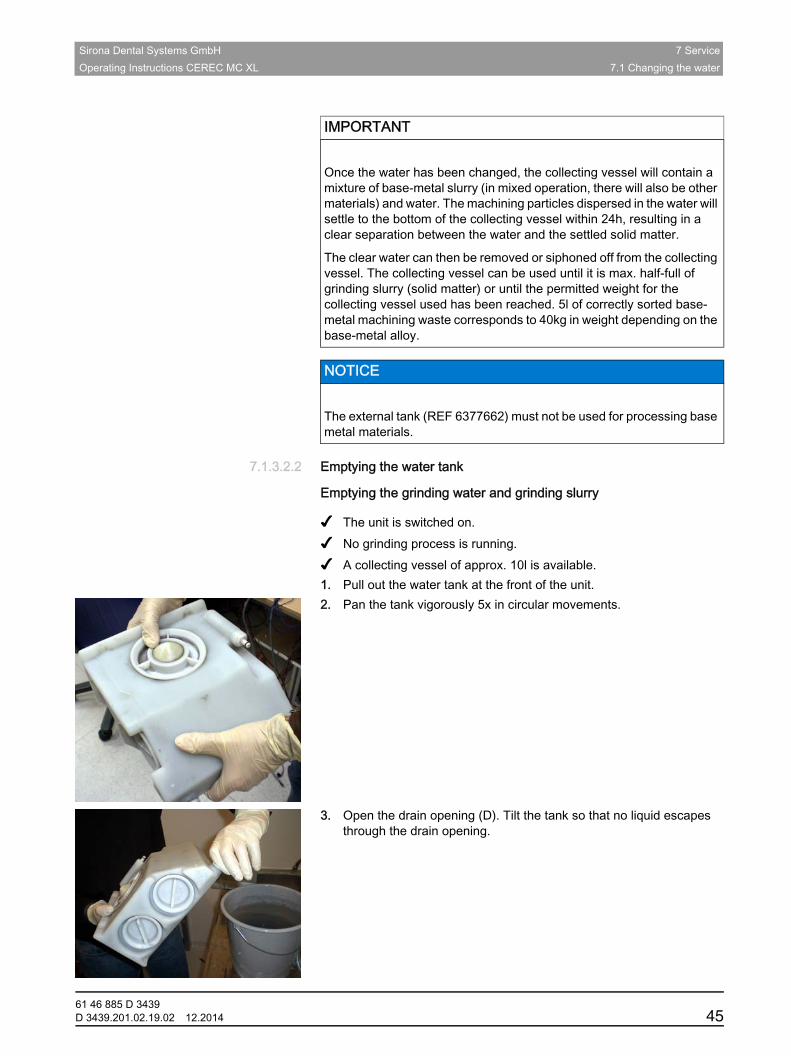
✔ The unit is switched on.✔ No grinding process is running.✔ A collecting vessel of approx. 10l is available.1. Pull out the water tank at the front of the unit.2. Pan the tank vigorously 5x in circular movements.
3. Open the drain opening (D). Tilt the tank so that no liquid escapes through the drain opening.
IMPORTANT
Once the water has been changed, the collecting vessel will contain a mixture of base-metal slurry (in mixed operation, there will also be other materials) and water. The machining particles dispersed in the water will settle to the bottom of the collecting vessel within 24h, resulting in a clear separation between the water and the settled solid matter.
The clear water can then be removed or siphoned off from the collecting vessel. The collecting vessel can be used until it is max. half-full of grinding slurry (solid matter) or until the permitted weight for the collecting vessel used has been reached. 5l of correctly sorted base-metal machining waste corresponds to 40kg in weight depending on the base-metal alloy.
NOTICE
The external tank (REF 6377662) must not be used for processing base metal materials.
61 46 885 D 3439D 3439.201.02.19.02 12.2014 45
7 Service Sirona Dental Systems GmbH7.1 Changing the water Operating Instructions CEREC MC XL
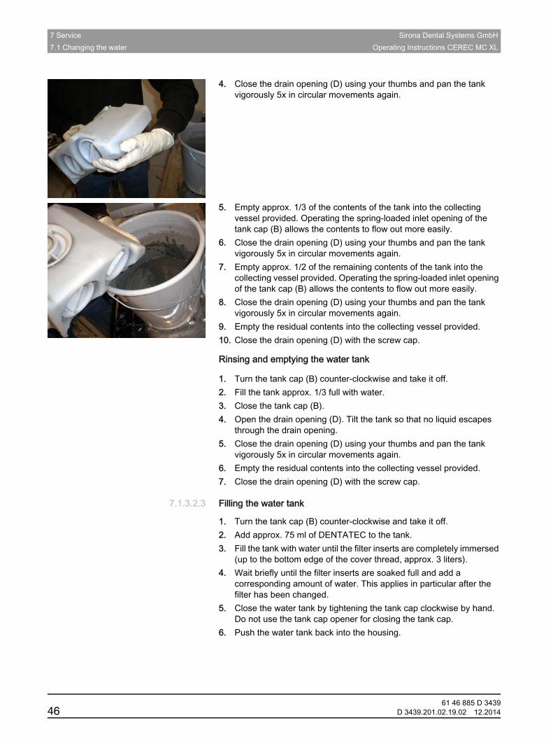
4. Close the drain opening (D) using your thumbs and pan the tank vigorously 5x in circular movements again.
5. Empty approx. 1/3 of the contents of the tank into the collecting vessel provided. Operating the spring-loaded inlet opening of the tank cap (B) allows the contents to flow out more easily.
6. Close the drain opening (D) using your thumbs and pan the tank vigorously 5x in circular movements again.
7. Empty approx. 1/2 of the remaining contents of the tank into the collecting vessel provided. Operating the spring-loaded inlet opening of the tank cap (B) allows the contents to flow out more easily.
8. Close the drain opening (D) using your thumbs and pan the tank vigorously 5x in circular movements again.
9. Empty the residual contents into the collecting vessel provided.10. Close the drain opening (D) with the screw cap.
Rinsing and emptying the water tank
1. Turn the tank cap (B) counter-clockwise and take it off.2. Fill the tank approx. 1/3 full with water.3. Close the tank cap (B).4. Open the drain opening (D). Tilt the tank so that no liquid escapes
through the drain opening.5. Close the drain opening (D) using your thumbs and pan the tank
vigorously 5x in circular movements again.6. Empty the residual contents into the collecting vessel provided.7. Close the drain opening (D) with the screw cap.
7.1.3.2.3 Filling the water tank
1. Turn the tank cap (B) counter-clockwise and take it off.2. Add approx. 75 ml of DENTATEC to the tank.3. Fill the tank with water until the filter inserts are completely immersed
(up to the bottom edge of the cover thread, approx. 3 liters).4. Wait briefly until the filter inserts are soaked full and add a
corresponding amount of water. This applies in particular after the filter has been changed.
5. Close the water tank by tightening the tank cap clockwise by hand. Do not use the tank cap opener for closing the tank cap.
6. Push the water tank back into the housing.
61 46 885 D 343946 D 3439.201.02.19.02 12.2014
Sirona Dental Systems GmbH 7 ServiceOperating Instructions CEREC MC XL 7.2 Instruments
båÖäáëÜ
7.2 Instruments
7.2.1 Overview of materials/instruments
7.2.1.1 CEREC MC XL BasicFragment Instrument combinationsFor a continuously updated table of approved instrument combinations, please visit the "www.sirona.com". To access the online portal for technical documentation, follow the "SERVICE" / "Technical Documentation" menu items in the navigation bar. The portal can also be accessed directly via the following address http://www.sirona.com/manuals Select your product there and then open the "Bur table" document.
7.2.1.2 CEREC MC XL with premium packageFragment Instrument combinationsFor a continuously updated table of approved instrument combinations, please visit the "www.sirona.com". To access the online portal for technical documentation, follow the "SERVICE" / "Technical Documentation" menu items in the navigation bar. The portal can also be accessed directly via the following address http://www.sirona.com/manuals Select your product there and then open the "Bur table" document.
7.2.2 Changing instruments
✔ The torque wrench from the draw of the grinding unit is ready-to-hand.
1. In the software, navigate to the system menu, and click on the "Configuration" button.
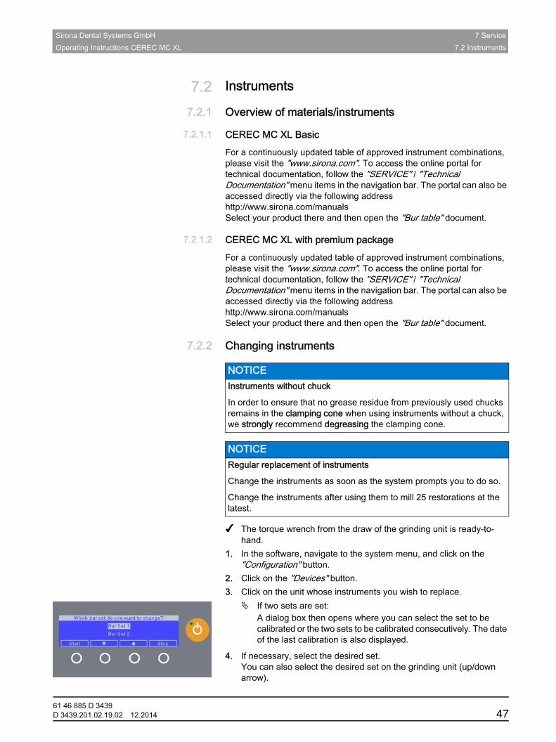
2. Click on the "Devices" button.3. Click on the unit whose instruments you wish to replace.
If two sets are set:A dialog box then opens where you can select the set to be calibrated or the two sets to be calibrated consecutively. The date of the last calibration is also displayed.
4. If necessary, select the desired set.You can also select the desired set on the grinding unit (up/down arrow).
NOTICE Instruments without chuck
In order to ensure that no grease residue from previously used chucks remains in the clamping cone when using instruments without a chuck, we strongly recommend degreasing the clamping cone.
NOTICE Regular replacement of instruments
Change the instruments as soon as the system prompts you to do so.
Change the instruments after using them to mill 25 restorations at the latest.
61 46 885 D 3439D 3439.201.02.19.02 12.2014 47
7 Service Sirona Dental Systems GmbH7.2 Instruments Operating Instructions CEREC MC XL
5. Click on the "Start" button. The motors travel to the change position for the instruments.
The dialog box for changing the instruments opens.
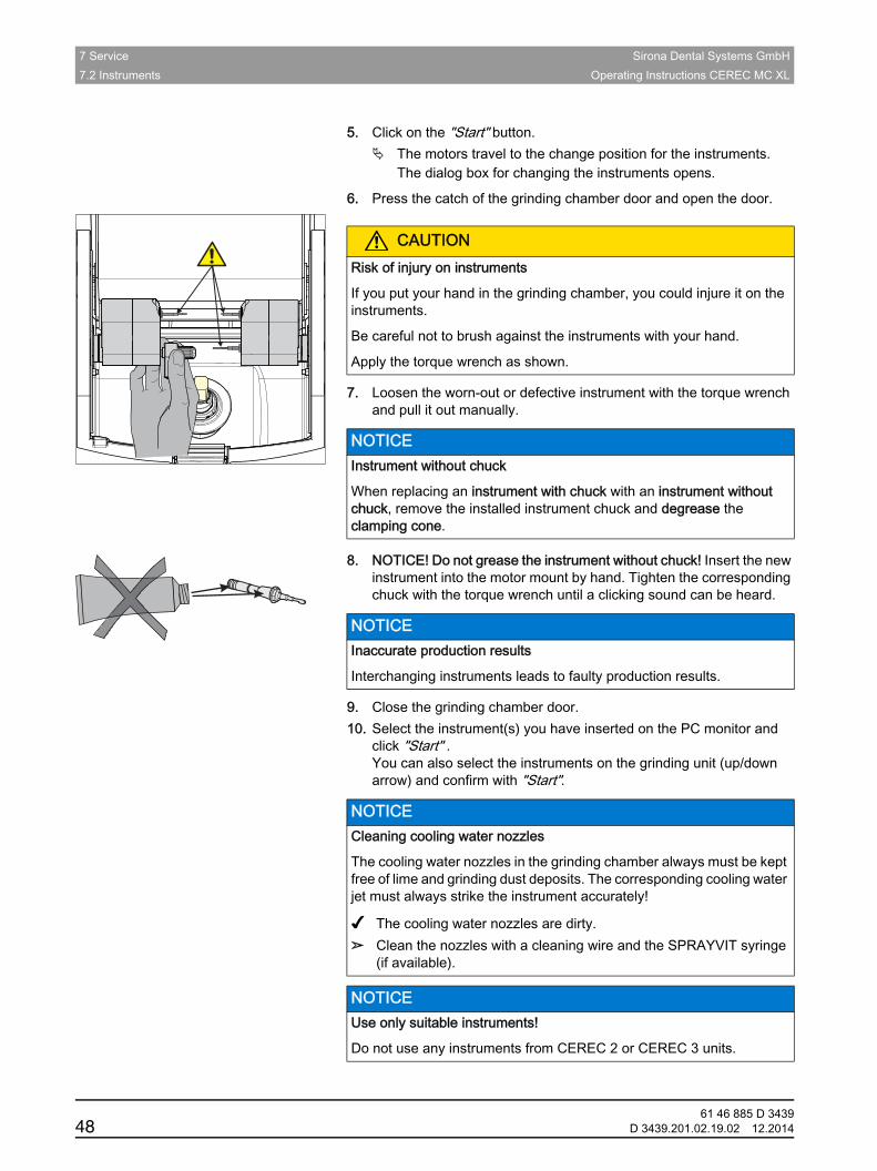
6. Press the catch of the grinding chamber door and open the door.
7. Loosen the worn-out or defective instrument with the torque wrench and pull it out manually.
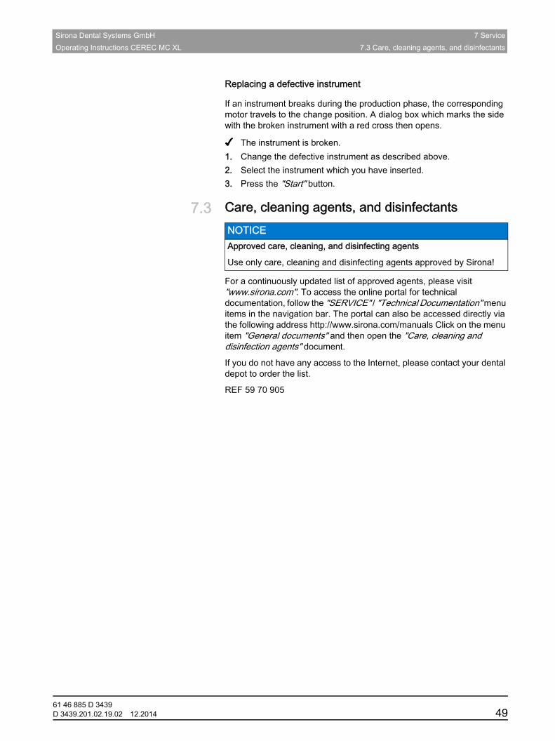
8. NOTICE! Do not grease the instrument without chuck! Insert the new instrument into the motor mount by hand. Tighten the corresponding chuck with the torque wrench until a clicking sound can be heard.
9. Close the grinding chamber door.10. Select the instrument(s) you have inserted on the PC monitor and
click "Start" .You can also select the instruments on the grinding unit (up/down arrow) and confirm with "Start".
Suitable instruments CEREC
CAUTIONRisk of injury on instruments
If you put your hand in the grinding chamber, you could injure it on the instruments.
Be careful not to brush against the instruments with your hand.
Apply the torque wrench as shown.
NOTICE Instrument without chuck
When replacing an instrument with chuck with an instrument without chuck, remove the installed instrument chuck and degrease the clamping cone.
NOTICE Inaccurate production results
Interchanging instruments leads to faulty production results.
NOTICE Cleaning cooling water nozzles
The cooling water nozzles in the grinding chamber always must be kept free of lime and grinding dust deposits. The corresponding cooling water jet must always strike the instrument accurately!
✔ The cooling water nozzles are dirty.➢ Clean the nozzles with a cleaning wire and the SPRAYVIT syringe
(if available).
NOTICE Use only suitable instruments!
Do not use any instruments from CEREC 2 or CEREC 3 units.
61 46 885 D 343948 D 3439.201.02.19.02 12.2014
Sirona Dental Systems GmbH 7 ServiceOperating Instructions CEREC MC XL 7.3 Care, cleaning agents, and disinfectants
båÖäáëÜ
Replacing a defective instrument
If an instrument breaks during the production phase, the corresponding motor travels to the change position. A dialog box which marks the side with the broken instrument with a red cross then opens.
✔ The instrument is broken.1. Change the defective instrument as described above.2. Select the instrument which you have inserted.3. Press the "Start" button.
7.3 Care, cleaning agents, and disinfectantsApproved care, cleaning, and disinfecting agents
Care, cleaning, and disinfecting agents, with REF numberFor a continuously updated list of approved agents, please visit "www.sirona.com". To access the online portal for technical documentation, follow the "SERVICE" / "Technical Documentation" menu items in the navigation bar. The portal can also be accessed directly via the following address http://www.sirona.com/manuals Click on the menu item "General documents" and then open the "Care, cleaning and disinfection agents" document.
If you do not have any access to the Internet, please contact your dental depot to order the list.
REF 59 70 905
NOTICE Approved care, cleaning, and disinfecting agents
Use only care, cleaning and disinfecting agents approved by Sirona!
61 46 885 D 3439D 3439.201.02.19.02 12.2014 49
7 Service Sirona Dental Systems GmbH7.4 Cleaning surfaces Operating Instructions CEREC MC XL
7.4 Cleaning surfaces
7.4.1 DisinfectingWipe surfaces down with a surface disinfectant (wiping disinfectant).
Observe the manufacturer’s instructions regarding restrictions for use.
7.4.2 Protection against medicamentsDue to their high concentrations and the substances they contain, many medicaments can dissolve, etch, bleach or discolor surfaces.
7.4.3 CleaningRemove dirt, grime and disinfectant residue regularly using mild, commercially available cleaning agents.
NOTICE Do not allow liquids to run into the ventilation slots!
NOTICE Damage to the surface
Clean the surface immediately with a moist cloth and a cleaning agent.
61 46 885 D 343950 D 3439.201.02.19.02 12.2014
Sirona Dental Systems GmbH 7 ServiceOperating Instructions CEREC MC XL 7.5 Replacing the main fuses
båÖäáëÜ
7.5 Replacing the main fusesWarning: main fuse
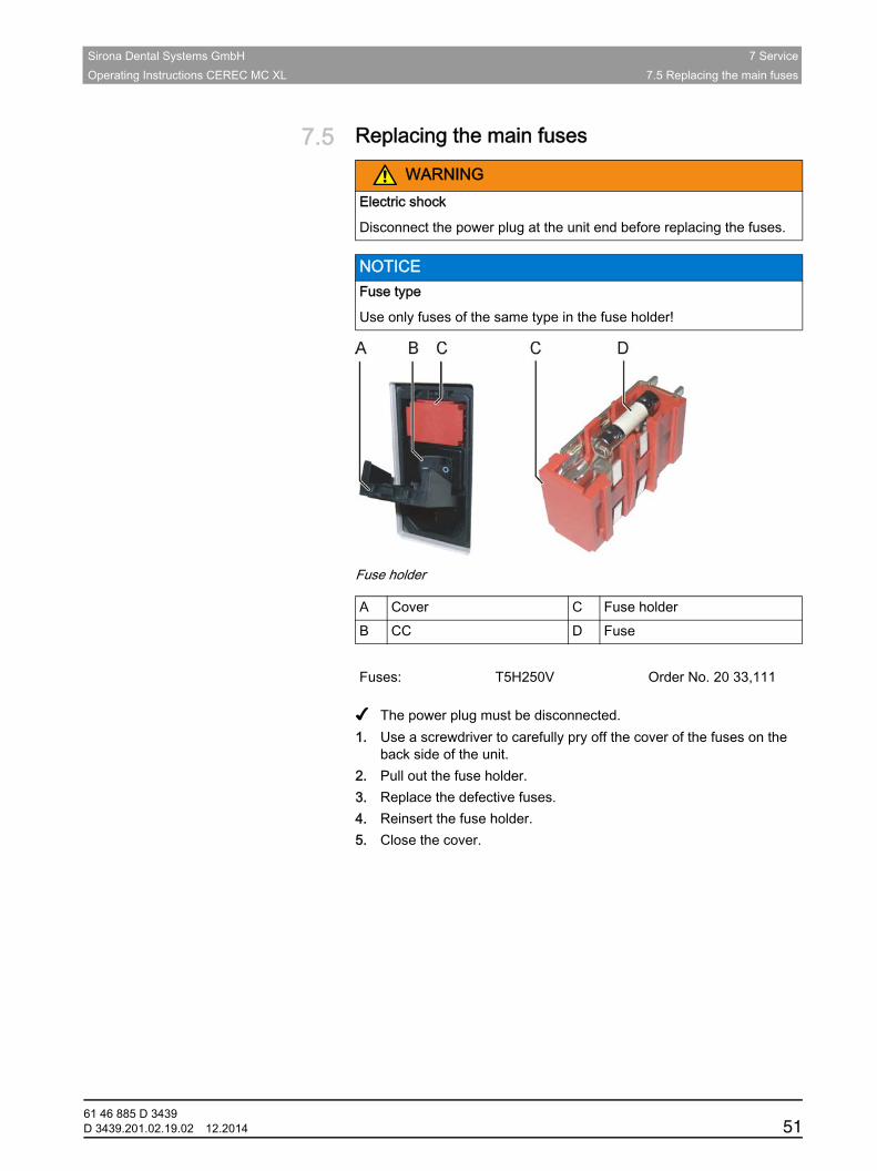
Fuse holder
Replacing fuses
✔ The power plug must be disconnected.1. Use a screwdriver to carefully pry off the cover of the fuses on the
back side of the unit.2. Pull out the fuse holder.3. Replace the defective fuses.4. Reinsert the fuse holder.5. Close the cover.
WARNINGElectric shock
Disconnect the power plug at the unit end before replacing the fuses.
NOTICE Fuse type
Use only fuses of the same type in the fuse holder!
A Cover C Fuse holderB CC D Fuse
Fuses: T5H250V Order No. 20 33,111
61 46 885 D 3439D 3439.201.02.19.02 12.2014 51
7 Service Sirona Dental Systems GmbH7.6 Changing the filter Operating Instructions CEREC MC XL
7.6 Changing the filter
7.6.1 CEREC MC XL Basic
CEREC water tank
Water tank
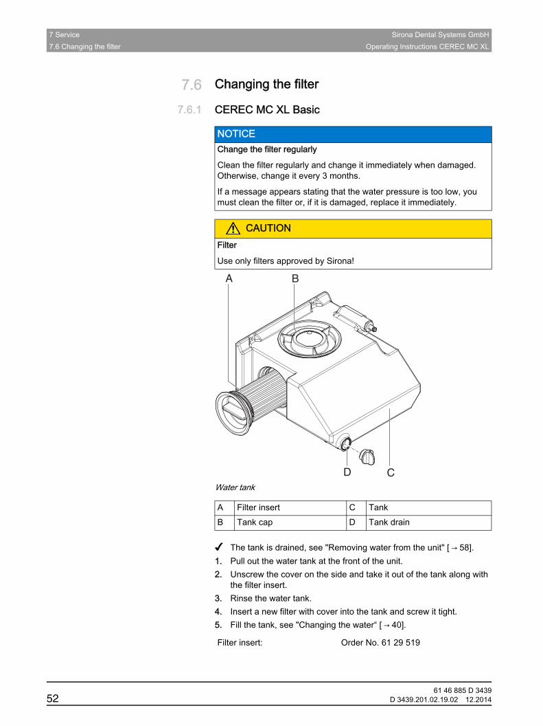
Fragment Change the filter water tank Basic✔ The tank is drained, see "Removing water from the unit" [ → 58].1. Pull out the water tank at the front of the unit.2. Unscrew the cover on the side and take it out of the tank along with
the filter insert.3. Rinse the water tank.4. Insert a new filter with cover into the tank and screw it tight.5. Fill the tank, see "Changing the water“ [ → 40].
NOTICE Change the filter regularly
Clean the filter regularly and change it immediately when damaged. Otherwise, change it every 3 months.
If a message appears stating that the water pressure is too low, you must clean the filter or, if it is damaged, replace it immediately.
CAUTIONFilter
Use only filters approved by Sirona!
A Filter insert C TankB Tank cap D Tank drain
Filter insert: Order No. 61 29 519
A
D
B
C
61 46 885 D 343952 D 3439.201.02.19.02 12.2014
Sirona Dental Systems GmbH 7 ServiceOperating Instructions CEREC MC XL 7.6 Changing the filter
båÖäáëÜ
7.6.2 CEREC MC XL with premium packageFragment Changing the filter regularly inLab+premium package
Fragment Sirona filters only
inLab water tank
Water tank
NOTICE Cleaning the filter
Clean the filter approx. every 12 to 15 units under running water, but at least with every water change.
NOTICE Change the filter inserts regularly!
Replace both filter inserts once a week or after every fourth water change.
If a message stating that the water pressure is too low appears, you must change the filter inserts.
NOTICE Filter
Use only filter cartridges approved by Sirona!
A Filter inserts C TankB Tank cap D Tank drain
A
A D
C
B
61 46 885 D 3439D 3439.201.02.19.02 12.2014 53
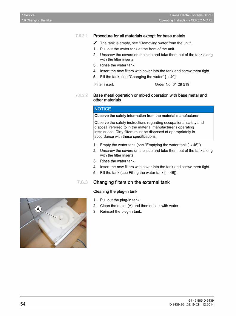
7 Service Sirona Dental Systems GmbH7.6 Changing the filter Operating Instructions CEREC MC XL
7.6.2.1 Procedure for all materials except for base metalsFragment Changing the filter inLab+premium package✔ The tank is empty, see "Removing water from the unit“.1. Pull out the water tank at the front of the unit.2. Unscrew the covers on the side and take them out of the tank along
with the filter inserts.3. Rinse the water tank.4. Insert the new filters with cover into the tank and screw them tight.5. Fill the tank, see "Changing the water“ [ → 40].
7.6.2.2 Base metal operation or mixed operation with base metal and other materialsFragment: Material manufacturer's safety information
1. Empty the water tank (see "Emptying the water tank [ → 45]“).2. Unscrew the covers on the side and take them out of the tank along
with the filter inserts.3. Rinse the water tank.4. Insert the new filters with cover into the tank and screw them tight.5. Fill the tank (see Filling the water tank [ → 46]).
7.6.3 Changing filters on the external tankCleaning the plug-in tank
Cleaning the plug-in tank
1. Pull out the plug-in tank.2. Clean the outlet (A) and then rinse it with water.3. Reinsert the plug-in tank.
Filter insert: Order No. 61 29 519
NOTICE Observe the safety information from the material manufacturer
Observe the safety instructions regarding occupational safety and disposal referred to in the material manufacturer's operating instructions. Dirty filters must be disposed of appropriately in accordance with these specifications.
61 46 885 D 343954 D 3439.201.02.19.02 12.2014
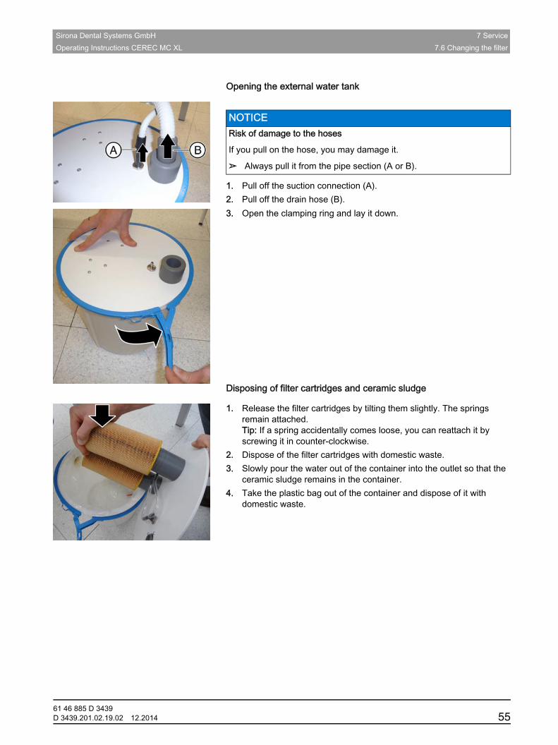
Sirona Dental Systems GmbH 7 ServiceOperating Instructions CEREC MC XL 7.6 Changing the filter
båÖäáëÜ
Opening the external water tank
Opening the external water tank
1. Pull off the suction connection (A).2. Pull off the drain hose (B).3. Open the clamping ring and lay it down.Disposing of filter cartridges and ceramic sludge
Disposing of filter cartridges and ceramic sludge
1. Release the filter cartridges by tilting them slightly. The springs remain attached. Tip: If a spring accidentally comes loose, you can reattach it by screwing it in counter-clockwise.
2. Dispose of the filter cartridges with domestic waste.3. Slowly pour the water out of the container into the outlet so that the
ceramic sludge remains in the container.4. Take the plastic bag out of the container and dispose of it with
domestic waste.
NOTICE Risk of damage to the hoses
If you pull on the hose, you may damage it.
➢ Always pull it from the pipe section (A or B).
61 46 885 D 3439D 3439.201.02.19.02 12.2014 55
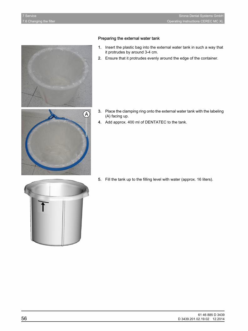
7 Service Sirona Dental Systems GmbH7.6 Changing the filter Operating Instructions CEREC MC XL
Preparing the external water tank
Preparing the external water tank
1. Insert the plastic bag into the external water tank in such a way that it protrudes by around 3-4 cm.
2. Ensure that it protrudes evenly around the edge of the container.
3. Place the clamping ring onto the external water tank with the labeling (A) facing up.
4. Add approx. 400 ml of DENTATEC to the tank.
5. Fill the tank up to the filling level with water (approx. 16 liters).
61 46 885 D 343956 D 3439.201.02.19.02 12.2014
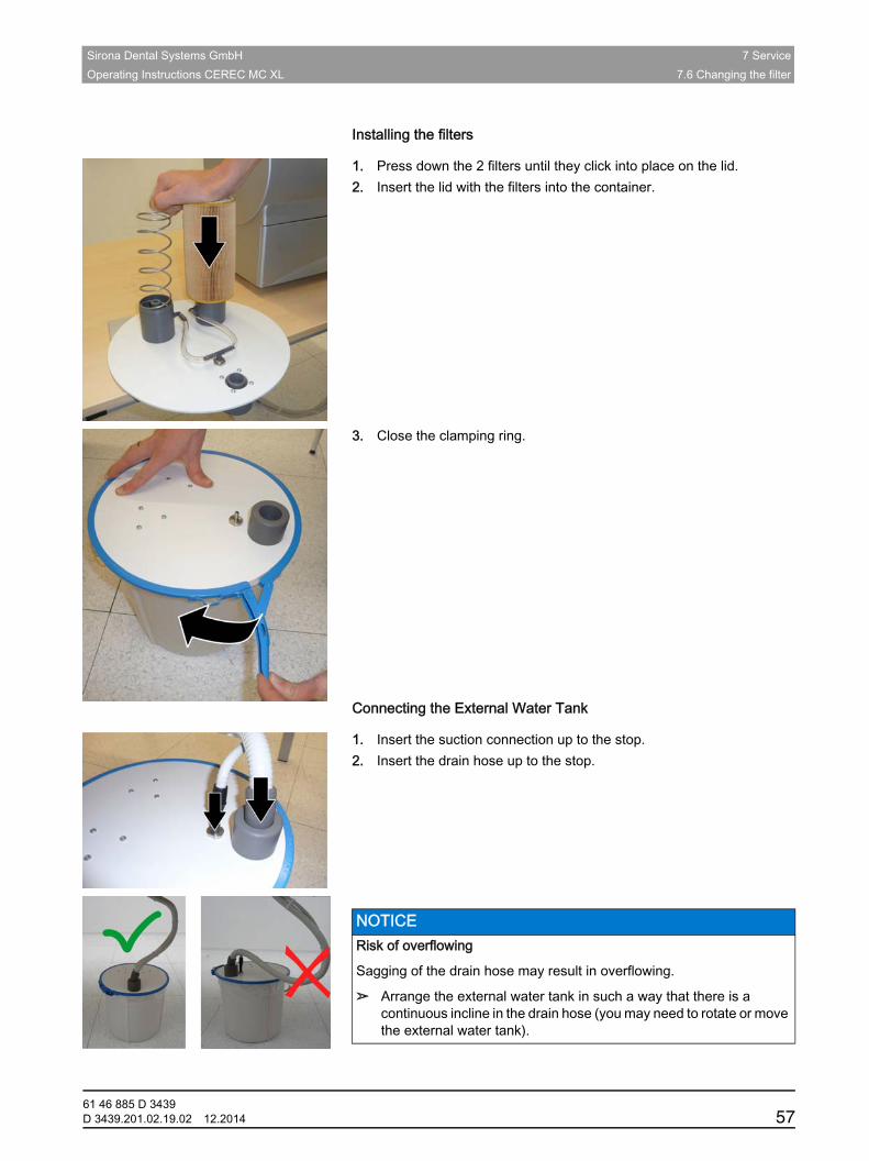
Sirona Dental Systems GmbH 7 ServiceOperating Instructions CEREC MC XL 7.6 Changing the filter
båÖäáëÜ
Installing the filters
Installing the filters
1. Press down the 2 filters until they click into place on the lid.2. Insert the lid with the filters into the container.
3. Close the clamping ring.Connecting the External Water Tank
Connecting the External Water Tank
1. Insert the suction connection up to the stop.2. Insert the drain hose up to the stop.
NOTICE Risk of overflowing
Sagging of the drain hose may result in overflowing.
➢ Arrange the external water tank in such a way that there is a continuous incline in the drain hose (you may need to rotate or move the external water tank).
61 46 885 D 3439D 3439.201.02.19.02 12.2014 57
7 Service Sirona Dental Systems GmbH7.7 Removing water from the unit Operating Instructions CEREC MC XL
7.7 Removing water from the unit
7.7.1 Procedure for all materials except for base metalsYou must remove water from the unit if you will not be using it for a long period of time or wish to transport it.
✔ No machining process is running.1. Switch the unit off.2. Pull out the water tank at the front of the unit.3. Drain the water out of the water tank through the drain opening and
reinsert the water tank in the unit.4. Switch the unit on.
5. Press the "Pump" key to switch the pump on. The water pump then starts pumping the water out of the unit.
Let the pump run until no more water escapes from the nozzles.
6. Press the "Pump" key to switch the pump off. 7. Pull out the water tank and empty it.8. Push it back into the housing.
7.7.2 Base metal operation or mixed operation with base metal and other materialsFragment: Material manufacturer's safety information
NEM inLab MC XL fragment1. Empty the water tank (see Emptying the water tank [ → 45]) and insert it back into the unit.
2. Switch the unit on.3. Press the "Pump" button to switch the pump on.
The water pump then starts pumping the water out of the unit.Let the pump run until no more water escapes from the nozzles.
4. Press the "Pump" button to switch the pump off. 5. Pull out the water tank and empty it.6. Push it back into the housing.
NOTICE Pump button active at power-up
The "Pump" button appears on the display when the grinding unit is switched on. You can start or stop the water pump by pressing this button.
NOTICE Observe the safety information from the material manufacturer
Observe the safety instructions regarding occupational safety and disposal referred to in the material manufacturer's operating instructions. Dirty filters must be disposed of appropriately in accordance with these specifications.
61 46 885 D 343958 D 3439.201.02.19.02 12.2014
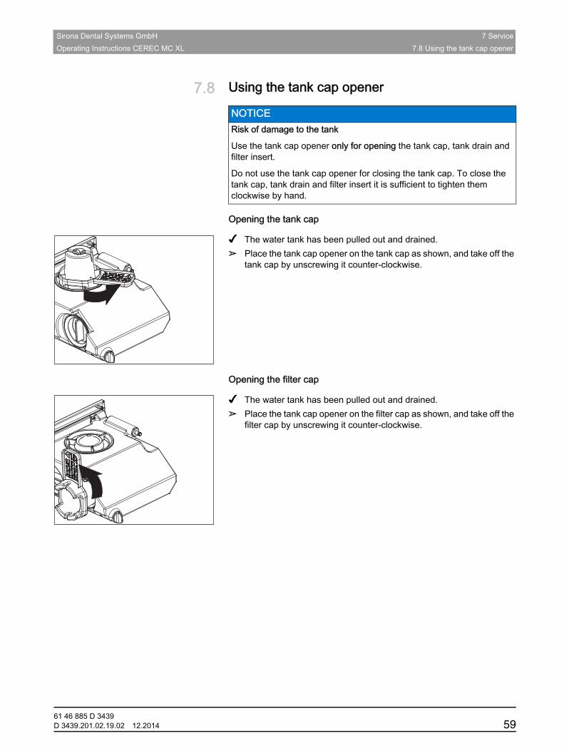
Sirona Dental Systems GmbH 7 ServiceOperating Instructions CEREC MC XL 7.8 Using the tank cap opener
båÖäáëÜ
7.8 Using the tank cap opener
Opening the tank cap
✔ The water tank has been pulled out and drained.➢ Place the tank cap opener on the tank cap as shown, and take off the
tank cap by unscrewing it counter-clockwise.
Opening the filter cap
✔ The water tank has been pulled out and drained.➢ Place the tank cap opener on the filter cap as shown, and take off the
filter cap by unscrewing it counter-clockwise.
NOTICE Risk of damage to the tank
Use the tank cap opener only for opening the tank cap, tank drain and filter insert.
Do not use the tank cap opener for closing the tank cap. To close the tank cap, tank drain and filter insert it is sufficient to tighten them clockwise by hand.
61 46 885 D 3439D 3439.201.02.19.02 12.2014 59
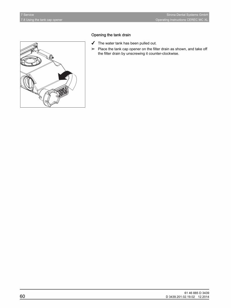
7 Service Sirona Dental Systems GmbH7.8 Using the tank cap opener Operating Instructions CEREC MC XL
Opening the tank drain
✔ The water tank has been pulled out.➢ Place the tank cap opener on the filter drain as shown, and take off
the filter drain by unscrewing it counter-clockwise.
61 46 885 D 343960 D 3439.201.02.19.02 12.2014
Sirona Dental Systems GmbH 8 Technical descriptionOperating Instructions CEREC MC XL 8.1 System requirements
båÖäáëÜ
8 Technical description
8.1 System requirements
8.1.1 CEREC MC XL BasicThe CEREC SW must only be installed on CEREC AC acquisition units.
The hardware version of the acquisition unit must be PC Hardware HQ with Windows 7 (64 bit) or higher.
If necessary, upgrade your operating system.Fragment from serial no. 126001Units as of serial no. 126001 are equipped with new stepping motors. The milling units can only be used in conjunction with CEREC SW 4.0.2 software, inLab SW 4.0.2 or more recent versions.
8.1.2 CEREC MC XL with premium packageThe CEREC SW/inLab software must only be installed on CEREC AC acquisition units or on the 64-bit inLab PC (optional). The hardware version must be PC Hardware HQ with Windows 7 (64 bit) or higher.
If necessary, upgrade your operating system.Fragment from serial no. 126001Units as of serial no. 126001 are equipped with new stepping motors. The milling units can only be used in conjunction with CEREC SW 4.0.2 software, inLab SW 4.0.2 or more recent versions.
8.2 Grinding and milling unit
8.2.1 General technical descriptionTechnical description of the grinding unit
Grinding instruments (performance-monitored, backlash-free bearing)
Fragment Milling instruments
● Digital feed control with force monitoring for extremely sensitive processing of ceramic materials
● Process-controlled grinding motors● Production repeatability: +/- 25 μm● Grinding speed: 1.0 - 1.5 mm/min.
● Grain size: 64 μm● Speed: 42,000 rpm● Step Bur 12 S● Step Bur 20 (only for CEREC MC XL with premium package)● Cyl. Pointed Bur 12 S● Cyl. Pointed Bur 20 (only for CEREC MC XL with premium package)
61 46 885 D 3439D 3439.201.02.19.02 12.2014 61
8 Technical description Sirona Dental Systems GmbH8.2 Grinding and milling unit Operating Instructions CEREC MC XL
Milling instruments
● Shaper 25 RZ● Shaper 25 (only for milling models)● Finisher 10
61 46 885 D 343962 D 3439.201.02.19.02 12.2014
Sirona Dental Systems GmbH 8 Technical descriptionOperating Instructions CEREC MC XL 8.2 Grinding and milling unit
båÖäáëÜ
8.2.2 Technical data
8.2.3 Controller board ● 3x 2-axis stepping motor controller with microstepping
● 2 (4) DC motor controllers with integrated speed and current control and force monitoring
● Ethernet, RJ45 interface 10 Mbit/sec
Type designation Grinding unit CEREC MC XLRated line voltage 100 V - 230 V ACRated power frequency 50/60 HzRated current 1.5 - 3.5 ANominal power output 320 VAPermissible line voltage fluctuations ±10% of nominal voltageType of protection against electric shock
Class 1 device
Degree of protection against ingress of water
Ordinary device (without protection against ingress of water)
Overvoltage category IIAmbient conditions For indoor use
Pollution degree 2
Air pressure: 700 hPa – 1,060 hPa
Temperature range 5 ℃ - 40 ℃Humidity range 80% rel. up to 31 °C
decreasing to 50% rel. up to 40 °C
Operating mode Continuous operationDimensions (WxHxD) in mm 700 x 425 x 420Approx. weight 43 kg
61 46 885 D 3439D 3439.201.02.19.02 12.2014 63
61 46 885 D 343964 D 3439.201.02.19.02 12.2014
9 Disposal Sirona Dental Systems GmbHOperating Instructions CEREC MC XL
9 DisposalEnvironmentally sound disposalYour product is marked with the adjacent symbol. Within the European Economic Area, this product is subject to Directive 2002/96/EC as well as the corresponding national laws. This directive requires environmentally sound recycling / disposal of the product. The product must not be disposed of as domestic refuse!
Please observe the disposal regulations applicable in your country.
Disposal procedure
Please note that this product is subject to the stipulations in EC Directive 2002/96 governing waste electrical and electronic equipment and must be disposed of in line with these special requirements within the European Union (EU).
Prior to disassembly / disposal of the product, it must be fully prepared (cleaned / disinfected / sterilized).
When disposing of equipment permanently, please proceed as follows:
In Germany:
To initiate return of the electrical device, please send a disposal order to "enretec GmbH".
1. You can find a form for placing a disposal order on the company's homepage (www.enretec.de) under the menu item "Entsorgung elektrischer und elektronischer Geräte" (Disposal of electric and electronic devices). The form can either be downloaded or completed online.
2. Fill out the form with the corresponding details and send it as an online order or fax it to enretec GmbH at +49(0)3304 3919 590. You can also get in touch with the following contacts for disposal orders and any questions relating to this you may have: Phone: +49(0)3304 3919 500; E-mail: [email protected] address: enretec GmbH, Geschäftsbereich eomRECYCLINGKanalstrasse 17, 16727 Velten
Any nonpermanently installed equipment will be picked up at its installation site in the practice. Permanently installed equipment will be picked up curbside at your address by appointment.
All disassembly, transport and packaging costs are to be borne by the owner / operator of the equipment. The disposal itself is free of charge.
Worldwide (outside Germany):
Please contact your local dental equipment specialist for country-specific information on disposal.
Sirona Dental Systems GmbH IndexOperating Instructions CEREC MC XL
IndexBBar code reader, 13
Building installation, 9
CCalibration tools
Calibration phantom, 28
Calibration pins, 28
Storage, 30
Care, cleaning, and disinfecting agents, 49
CE mark, 8
Changing
Instruments, 47
Connection
Ethernet, 19
LAN, 19
Cooling water nozzles, 48
DDimensions, 63
Disinfectant, 50
Disposal
Disposal of electronic and electrical equipment, 64
EEthernet
LAN port, 13
Ffilter
change, 52, 53
Order No., 52, 54
floor space, 12
Fuse, 13
Fuse type, 51
Order No., 51
replacement, 51
GGrinding instruments, 61
Grinding speed, 61
Grinding unit
Display, 17
Grinding chamber, 14
HHumidity range, 63
IInstallation site, 12
installing unit
manually, 20
Instruments, 48
Replacing a defective instrument, 49
Intended use, 8
MMain switch, 13
Maintenance, 9
Regulations, 39
Milling unit
Overview, 13
OOperating mode, 63
PPackaging, 11
Packing, 26
port
WLAN, 21
Ports, 13
Power connection, 13
Product safety, 10
Protection class, 63
61 46 885 D 3439D 3439.201.02.19.02 12.2014 65
Index Sirona Dental Systems GmbHOperating Instructions CEREC MC XL
RRated current, 63
Rated line voltage, 63
Repair, 9
SSafety information, 6
Scope of supply, 26
TTemperature range, 63
Transport, 11
Type designation, 63
UUnit installation
automatically, 19
Unit removal
removal, 20
Unpacking, 11
Usage purpose, 8
WWater, 63
Water tank
Change water, 42, 43
Filling the, 23, 24
Odors, 41
Overview, 23, 24, 43, 52, 53
Removing water from the unit, 58
Water change, 40
Weight, 63
61 46 885 D 343966 D 3439.201.02.19.02 12.2014

tÉ=êÉëÉêîÉ=íÜÉ=êáÖÜí=íç=ã~âÉ=~åó=~äíÉê~íáçåë=ïÜáÅÜ=ã~ó=ÄÉ=êÉèìáêÉÇ=ÇìÉ=íç=íÉÅÜåáÅ~ä=áãéêçîÉãÉåíëK
«=páêçå~=aÉåí~ä=póëíÉãë=dãÄe=OMMSJOMNQ péê~ÅÜÉW ÉåÖäáëÅÜ mêáåíÉÇ=áå=dÉêã~åóa=PQPVKOMNKMOKNVKMO NOKOMNQ ûKJkêKW= NOM=MMR
páêçå~=aÉåí~ä=póëíÉãë=dãÄeáå=íÜÉ=rp^W
c~Äêáâëíê~≈É=PNaJSQSOR=_ÉåëÜÉáãdÉêã~åóïïïKëáêçå~KÅçã
páêçå~=aÉåí~ä=póëíÉãë=ii`QUPR=páêçå~=aêáîÉI=pìáíÉ=NMM`Ü~êäçííÉI=k`=OUOTPrp^
lêÇÉê=kç SN=QS=UUR=a=PQPV


![4)- 4SYPXV] *%( )QIVKIRG] 6IWTSRWI 6IWSYVGI 1ERYEP · pÉÅíáçå=p aáëÉ~ëÉ=fåÅáÇÉåí=~åÇ=^äÉêí=aÉÑáåáíáçåë kkkkkkkkkkkkkkkkkkkkkkkkkkkk pkn iÉîÉä=n=Ó=dêÉÉålkçêã~ä=léÉê](https://img.pdfslide.tips/doc/110x75/6006300b801a2b6ebe11f91b/4-4sypxv-qivkirg-6iwtsrwi-6iwsyvgi-pp-afa.jpg)