Embed Size (px)
Citation preview
복합시스템 설계 및 제어 연구실(Hybrid System Design & Control Laboratory HySDC Lab )
HySDC LAB복합시스템 설계및제어 연구실
지도교수 : 정 성 종 (Sung-Chong Chung)1979, 한양대학교 공과대학 기계공학과 (B.S.)
(Hybrid System Design & Control Laboratory, HySDC Lab. )
교육 및 연구 목표
1981, KAIST 기계공학과 (M.S.)1987, KAIST 기계공학과 (Ph. D.)
교육 및 연구 목표
첨단기계장비, 로봇, 자동차 등 기계 전자기 비전 기술 등이 복합된 기계시스템의 고속화, 정밀화자동화 기술 개발을 위해 CAD/CAM, 정밀공학, MECHATRONICS 분야의 기술을 선도한다.
연락처연락처
전 화: 02-2220-0444, 02-2296-2750이메일: [email protected], 홈페이지 : http://hysdc.hanyang.ac.kr실험실: M-102 M-103 (공업센터 1층) A-217(공업센터별관 2층)실험실: M 102, M 103 (공업센터 1층), A 217(공업센터별관 2층)
수상 경력
International Journal of Machine Tools and Manufacture (Editorial Board Member)미국생산공학회 (SME/NAMRI) 우수논문상 (2000년 5월)대한기계학회 효석학술상 (2003년 11월)한국CAD/CAM학회 CAD소프트웨어개발 은상 (2004년 2월)한국CAD/CAM학회 CAD소프트웨어개발 대상 [정보통신부장관상] (2005년 1월)
Hybrid System Design and Control Lab.
한국 학회 웨어개발 대상 [정 통신부장관상] ( 월)Who’s Who in the World; Who’s Who in Science and Engineering; Who’s Who in Finance and Industry, etc.

첨단기계장비, 로봇, 자동차 등 복합시스템의 고속화, 정밀화, 자동화 기술개발을 위해CAD/CAM, 정밀공학, MECHATRONICS 분야의 Integrated Design 기술을 연구한다.
Hybrid System Design and Control Lab.

Integrated Design for High Performance Servos (1/2)서보 시스템 기계요소 규명법 서보서보 시스템시스템 기계요소기계요소 규명규명 결과결과서보 시스템 기계요소 규명법 서보서보 시스템시스템 기계요소기계요소 규명규명 결과결과
90
100
110
de (d
B)
F .R .F .
Estim ated T F
70
80
90
Mag
nitu
-90
0
g) F .R .F .
Estim ated T.F .
101 102 103 104-450
-360
-270
-180
90
Pha
se (d
eg
E stim ated T.F .
Frequency (rad/sec)서보 시스템 정적오차(pitch error) 보상
0.020 0.020보상전위치오차 보상후위치오차
0 005
0.010
0.015
h er
ror (
mm
)
0 005
0.010
0.015
h er
ror (
mm
)
0 50 100 150 200 250-0.005
0
0.005
Pitc
0 50 100 150 200 250-0.005
0
0.005
Pitc
h
Hybrid System Design and Control Lab.
Position (mm)0 50 100 150 200 250
Position (mm)

서보 시스템 실시간 제어블록 구성도
Integrated Design for High Performance Servos (2/2)
서보 시스템 실시간 제어블록 구성도
-K-
FFCGain
Positinon Command Torque
cFrictionX.c
danipcie.ccYoiCounterNew.c
X-axis Plant
Torref
Terminator
Saturation
PosErr
PID Controller
Mode
Interpolator
Friction compensator
-K-
FBCgainTorque input
Velocity Torque
command
1
X-AxisTorque
Position
VelocityPID ControllerXc
Yc
Circualr Motion Generator
cCircleCommand.c
cPID SI XP cSwitch
Disturbance observer
feedbackcPID_SI_XP.c
서보 시스템 통합설계 결과
0
0.02 (mm)90
120 0
0.02 (mm)90
120
서보 시스템 통합설계 결과
PID only0.04
0.06일반서보시스템 통합설계된서보시스템
-0.04
-0.02 30150
180 0
-0.04
-0.02 30150
180 0
-0 02
0
0.02
PID+DOB
PID+Friction comp.Integrated design
210
240270
300
330 210
240270
300
330
-0.06
-0.04
-0.02
Ti ( )9 9.5 10 10.5 11 11.5 12
PID DOB
Hybrid System Design and Control Lab.
270 270Time (sec)

Fuzzy Logic Control of Shaft Straightening Machines (1/2)
QQ S l
servovalve & cylinder
controller
sAp
33점점 굽힘굽힘 공정공정 모델모델
Permanent Deflection
Punch Stroke Control SystemShaft Straightening Machine
QinQout Servovalve
LoadMotor
D Fi xv QL -+
controller
P 3-Point-Bending
Cal. ofCal. of
+
-)(sGc 1s
Ksvsv qK sVK
A
et
c
p
4P M S
M MS
F Fk k
Springback
LoadCell Encoder
ServoAmplifier
PLC
OUT IN
Cal. ofCal. of
Permanent Deflection Observer
0k0kFP 0 0k k
LVDT
Anvil
AMP & A/D DIO D/AAMP & A/D
Observer
DIO D/A
Controller
MICRO COMPUTERDatabase
F
x xL
Hybrid System Design and Control Lab.
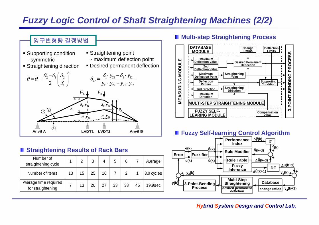
Multi step Straightening Process
Fuzzy Logic Control of Shaft Straightening Machines (2/2)
Supporting condition - symmetric
DeflectionLimits
MaximumDeflection Value
ChangeRatios
D i d P t
DATABASEMODULE
CES
S
LE
영구변형량 결정방법
Straightening point - maximum deflection point
Multi-step Straightening Process
sy et c Straightening direction 2nd
Deflection ValueMaximum
Deflection Point
Deflection Value
DeflectionPattern
StraighteningPoint
Desired PermanentDeflection
SupportingCondition
St i ht i ND
ING
PR
OC
RIN
G M
OD
UL
2
2 1 21
12
1 22 2 12
11 22 21 12D
y yy y y y
p Desired permanent deflection
F1 F2
1 2
y21D.y11D
.
12
2nd Direction StraighteningDirection
CompensationFUZZY SELF-
MULTI-STEP STRAIGHTENING MODULE
3-PO
INT-
BE
MEA
SUR
MaximumDirection
Anvil A Anvil BLVDT1 LVDT2
d2 y12.d d2y22
.d
3
CompensationValue
FUZZY SELFLEARING MODULE
(k)Fuzzy Self-learning Control Algorithm
Number ofstraightening cycle 1 2 3 4 5 6 7 Average
PerformanceIndex
Rule TableFuzzifierError
e(k)
c(k)
y(k)
e(k)^
c(k)
+
+Rule Modifier v(k-d)^ r(k)
u(k-d)^
Straightening Results of Rack Bars
straightening cycle
Number of items 13 15 25 16 7 2 1 3.0 cycles
Average time requiredfor straightening
7 13 20 27 33 38 45 19.9sec
DF
3-Point-BendingProcess desired permanent
Multi-StepStraightening
yd(k)
yd(k+1)y(k)
+-
change ratios
Database
u(k+1)^
u(k+1)FuzzyInference
yd(k) + +
Hybrid System Design and Control Lab.
for straightening pdefletion
yd(k+1)change ratios

e 기반 사출금형 설계/제조 자동화 시스템
Pre-&PostProcessor
Web-based Collaborative System for Design and Manufacture
e-기반 사출금형 설계/제조 자동화 시스템
금형업체와 사출업체가 대부분 지역적으로 분산된 환경에 놓여 있기때문에 설계 및 제작상의 문제점 수정을 위해 많은 비용과 시간이 소모되며 설계 변경에 대한 빠른 대응이어렵다.
이를 해결하기 위해 네트워크 기술
DesignerGroup
InternetCMM
Inspector
Integrated Server
DMIS
Client
이를 해결하기 위해 네트워크 기술을 이용한 협동과 여기에서 발생하는문제점을 해결하기 위한 네트워크 기반의 협동 설계에 대한 연구를 진행한다
Native File TranslatorInternet ComputingEnvironment
...
...
한다. DMIS TranslatorApplication Server
Any CAD SystemInternet
Web Server
Native
Geometry, Topology, Material, Dimensions
Data Viewer
Designer
InspectorGroup
ManufacturerGroup
NativeFile
Real-time Multi-viewing Design & Dimension VerificationWeb based Intelligent CMM
3D Modeling Kernel Handling Real-time Collaboration Dimension & Draft Verification
Tolerances, Assembled structure Designer
Hybrid System Design and Control Lab.
Web-based Intelligent CMM CAD Data Interface
Dimension & Draft Verification Markup & Annotation
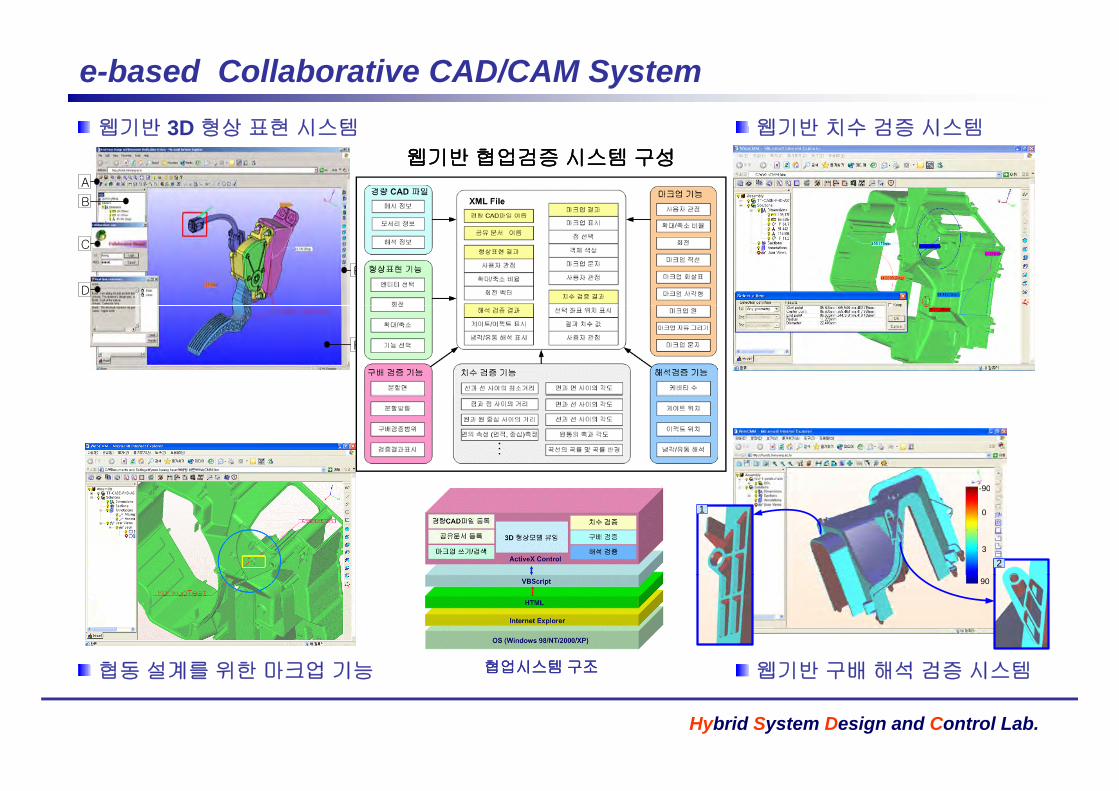
웹기반 치수 검증 시스템
e-based Collaborative CAD/CAM System웹기반 3D 형상 표현 시스템 웹기반 치수 검증 시스템
A
B
웹기반 3D 형상 표현 시스템
웹기반웹기반 협업검증협업검증 시스템시스템 구성구성
C
D
E
F
90-90
0
3
1
2
90
웹기반 구배 해석 검증 시스템협동 설계를 위한 마크업 기능 협업시스템협업시스템 구조구조
Hybrid System Design and Control Lab.
웹기반 구배 해석 검증 시스템협동 설계를 위한 마크업 기능 협업시스템협업시스템 구조구조

Precision 3D Measurement RobotLayout 머신 자동제어기 구성 Layout 머신 사용자 인터페이스Layout 머신 자동제어기 구성
Position, Velocity commmand
PC - MMIJoy-stick
I l
Layout 머신 사용자 인터페이스
Controller
monitoring
InterpolatorGenerate path
- Linear- Circular- Spline
Digital controllerF db k t l
InterfaceCurrent
controller
current
position, velocity feedback
VoltageFeedback control- Position control- Velocity control
Acc&Dec control- Trapezoid profile- S-curve profile
A/D D/ADI/O
Counter
Motor
Layout 머신의 자동/수동 측정 실험
자동 측정x
yLeqK L
eqK
Layout 머신 모드해석
수동 측정자동 측정
(NC)Beam elementeqK
eqK z
0.5Mode shape : x20 / f 7
-120
-100 33.43 169.28242.65
394.14
RECEPTANCE
수동 측정
(Joystick)
1
-0.5
0
Y
1st Mode shape2nd Mode shape3th Mode shape
240
-220
-200
-180
-160
-140
Mag
nitu
de(m
/N) [
dB]
Hybrid System Design and Control Lab.
0 0.5 1 1.5 2-1
Arm Coordinate[m]101 102 103
-240
Frequency[Hz]

Reverse Design / Engineering for CAD/CAM Reverse Engineering
Reverse Engineering• 점 데이터 측정• 기하학적 곡면 모델링• NC가공 코드 생성
계
• 상업용 CAD와 연계
Acquisition Measured data
CAD Interface
Surface Inspection Fitting, Fairing
Mean Value : 17.9mStandard Deviation : 12 1 mError distribution for inspection region ‘A’ : Eave = 7 2 m
Interface with a commercial CAD/CAM system
Hybrid System Design and Control Lab.
Standard Deviation : 12.1 mError distribution for inspection region A Eave 7.2 mError distribution for inspection region ‘B’ : Eave = 7.2 m

Mona-Lisa (painting) Venus (sculpture)
3D Reconstruction for CAD Interface Mona-Lisa (painting) Venus (sculpture)
Golden-Gate-Bridge (photograph)
Reconstructed 3D CAD File
Hybrid System Design and Control Lab.

3D Reconstruction for CAD/CAM
Original image Result of 3D
Visualized 3D CAD model onOriginal image
(photograph)
Result of 3D reconstruction
model on Power-Mill
Hybrid System Design and Control Lab.
Generation of tool-path (Power-Mill) Result of high-speed-machining (Mold) Injection molded part
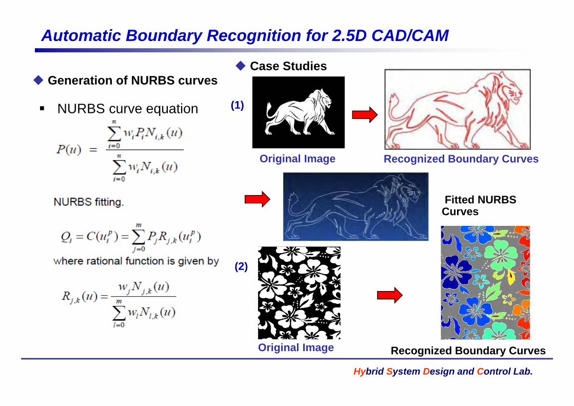
Automatic Boundary Recognition for 2.5D CAD/CAM
Case Studies Generation of NURBS curves
NURBS curve equation
Case Studies
(1)NURBS curve equation
Original Image Recognized Boundary Curves
( )
Original Image Recognized Boundary Curves
Fitted NURBSFitted NURBS Curves
(2)
Hybrid System Design and Control Lab.
Original Image Recognized Boundary Curves

Crack-free Glass Micro-Engraving linked with 2.5D CAD/CAM
IGES translation
CAD Model on CATIAMachining Simulation on PowerMill
translation
CAD Model on CATIA
2.5D Embossed Result
Hybrid System Design and Control Lab.
CAD Model on PowerMill Machining on the Glass on the Glass
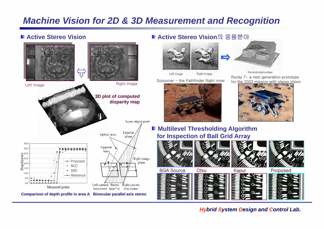
Machine Vision for 2D & 3D Measurement and RecognitionActive Stereo Vision의 응용분야Active Stereo Vision Active Stereo Vision의 응용분야Active Stereo Vision
Sojourner - the Pathfinder flight roverLeft Image Right Image
Rocky 7- a next generation prototype for the 2003 mission with stereo vision
3D plot of computed disparity map
Multilevel Thresholding Algorithm for Inspection of Ball Grid Array
20.00
25.00
30.00
35.00
40.00
epth
(mm
)
Proposed
NCC
ProposedBGA Source Otsu Kapur
0.00
5.00
10.00
15.00
Measured points
De NCC
SSD
Reference
Hybrid System Design and Control Lab.
Comparison of depth profile in area AComparison of depth profile in area A Binocular parallel axis stereoBinocular parallel axis stereo

Machine Vision for 3D Micro-MeasurementMachine Vision System Shape form Focus System 가공된 구멍의 위치 및 확대 오차
CCDcamera
Machine Vision System Shape form Focus System...1 2 10 11
가공된 구멍의 위치 및 확대 오차
Zoom lens
CCD camera
Coaxial
LED light
Stepnumber
Zoomlens
4
SeatN=3
N=n
Raw and edge detected images
Linear scale
Coaxialhalogen light
N=3
Focusedobject plane
45 oN=n
z
N=0N=1N=2
Servo motor
Lightsource
N=0N=1N=2
Movingresolution
Referenceplane
d미소드릴링시 버의 3차원 형상 측정
Hole No. 1 2 3 4 5 6
Diametral error [um] 7.42 7.51 7.59 10.01 8.02 7.88
Location error [um] 22.58 30.33 28.28 40.63 13.76 33.03
Burr Height
[um]
Max Height Circle Square Triangle
195.09 185.12~195.09 138.37~148.63 88.29~103.68
Burr Width
[ ]
Burr Width A Burr Width B Burr Width C Burr Width D
Location degree [° ] 226 292 271 184 296 121
Hole No. 7 8 9 10 11 Mean
Diametral error [um] 9.92 8.01 10.50 9.68 7.75 8.57
Location error [um] 15.29 11.77 13.97 15.54 24.24 22.67
Location degree [° ] 69 70 103 91 97
Hybrid System Design and Control Lab.
[um] 292.25 144.23 133.65 162.02Location degree [ ] 69 70 103 91 97 -
Circumferential dir
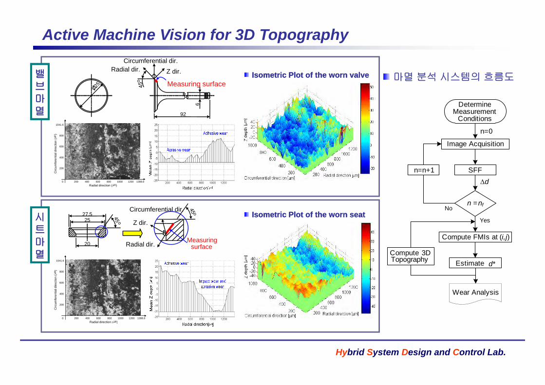
Active Machine Vision for 3D Topography
밸밸브브마마
Circumferential dir.Radial dir.
6
Measuring surface
Z dir. Isometric Plot of the worn valveIsometric Plot of the worn valve
Determine
마멸 분석 시스템의 흐름도
멸멸1041.6
rect
ion
(㎛)
600
800
6
92
Image Acquisition
DetermineMeasurement
Conditions
n=0
1388.80Radial direction (㎛)
Circ
umfe
rent
ial d
ir
200 400 600 800 1000 1200
400
200
dSFFn=n+1
시시트트
2527.5
Z dir.
Circumferential dir. n = nf
Compute FMIs at (i j)
Yes
NoIsometric Plot of the worn seatIsometric Plot of the worn seat
마마멸멸
1041.6
on (㎛
) 800
20 Measuring surfaceRadial dir.
Compute FMIs at (i,j)
Estimate d*Compute 3DTopography
1388.80Radial direction (㎛)
Circ
umfe
rent
ial d
irect
i
200 400 600 800 1000 1200
600
400
200
Wear Analysis
Hybrid System Design and Control Lab.
( )

Realtime 6-DOF Laser Measurement System for Precision Servos
다자유도 초정밀측정시스템
모든 이송체의 운동오차= 3개의 병진운동 오차+ 3개의 회전운동 오차
길이측정오차 : 10nm/10m각도측정오차 : 0.2arcsec/10m
y x
Laser HeadBB
Optical System of 6DOF Error Measurement
PD2
z
BS
BS
BB
QPD3BS
ExpansionLens set
BB
L2
BS
L1
Arithmetic Position Sensing Unit
Error Generating Mechanism
PBS
PBS
BS
PD1
PD4
Reference RR
BS
QPD1QPD2
BS
Polarizer
BB
L+ L /4 Plate
g
PD3 /2 Plate
S l i d e
RR1MirrorRR2
D
RR3
Direction of travel
PBS
Hybrid System Design and Control Lab.
D

Active Magnetic Bearing Systems
Data Acquisition SystemCurrentSSensor
Power Amp.Sensor Amp. Oscilloscope
AMB System
+Digital/Analog
+
DSP(TMS320C)
g gPID Controller
S h ti Di f A ti M ti B i S t
PC
Hybrid System Design and Control Lab.
Schematic Diagram of Active Magnetic Bearing Systems
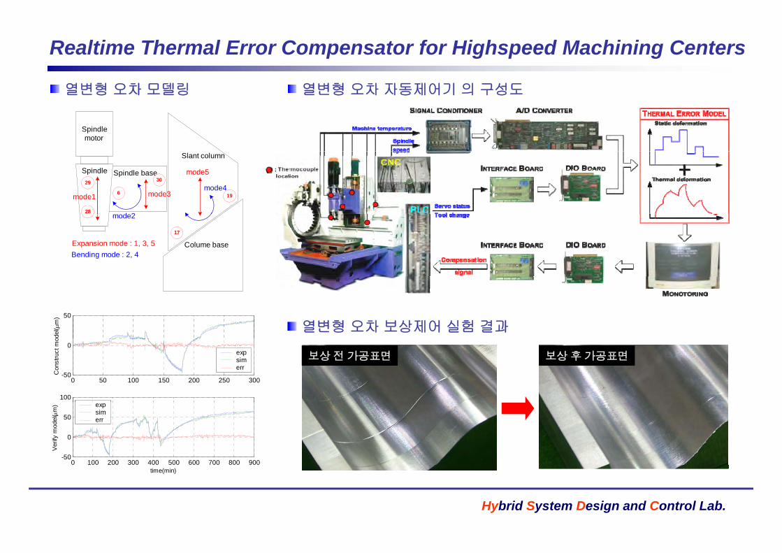
Realtime Thermal Error Compensator for Highspeed Machining Centers
열변형 오차 모델링 열변형 오차 자동제어기 의 구성도열변형 오차 모델링
Spindlemotor
열변형 오차 자동제어기 의 구성도
Spindle baseSpindle
Slant column
mode1
d 2
mode3
mode5
mode429
28
6
30
19
Colume base
mode2
17
Bending mode : 2, 4 Expansion mode : 1, 3, 5
50
odel
( m
)
열변형 오차 보상제어 실험 결과
0 50 100 150 200 250 300-50
0
Con
stru
ct m
o
expsimerr
100
보상전가공표면 보상후가공표면
0 100 200 300 400 500 600 700 800 900-50
0
50
Ver
ify m
odel
( m
) expsimerr
Hybrid System Design and Control Lab.
time(min)
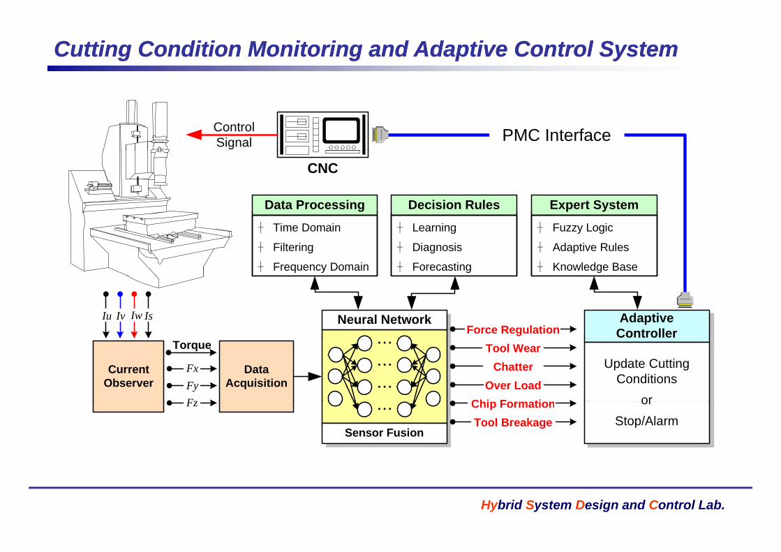
Cutting Condition Monitoring and Adaptive Control SystemCutting Condition Monitoring and Adaptive Control System
PMC InterfaceControlSignal
Expert SystemData Processing Decision Rules
CNC
� Fuzzy Logic
� Adaptive Rules
� Knowledge Base
� Time Domain
� Filtering
� Frequency Domain
� Learning
� Diagnosis
� Forecasting
Force RegulationNeural Network Adaptive
ControllerIsIwIvIu
CurrentObserver
Torque
DataAcquisition
Tool WearChatter
Over LoadChi F ti
…
…
…
Update Cutting Conditions
or
FxFyF Chip Formation
Tool Breakage…
Sensor Fusion
or Stop/Alarm
Fz
Hybrid System Design and Control Lab.

SensorlessSensorless Monitoring Monitoring and Adaptive Control Systemand Adaptive Control System
Dynamometer(1) Estimation of Depth of Cuts
(3) Rapid Calibration(2) Cutting Force Estimaiton
Depth of CutsDepth of Cuts
M
easu
rmen
t
RrR
aRrR
Cutting Mechanism
CuttingProcess
FORCEyx FF
CuttingProcess
Force Estimation
M
Tool
orkp
iece
s
aR
21 rrKS Processtz FF Servo
System
atio
n
Wo
Cur
rent
s
szyx IIII
FeedrateSpindle Speed Feedrate
Spindle Speed App
lica
Robust Control
Robust ControlMonitoring ...
(4) Intelligent Mechatronic System
Hybrid System Design and Control Lab.
( ) g y