Embed Size (px)
Citation preview
Erstantie 2, FIN-15540 Villähde AEP steel bracketTel +358-3-872 200 [email protected] www.anstar.eu 3
CONTENTS page
1. PRODUCT DESCRIPTION ....................................................................................................................................... 41.1 General................................................................................................................................................................... 41.2 Product types .......................................................................................................................................................... 4
2. MATERIALS AND STRUCTURE............................................................................................................................. 52.1 Materials ................................................................................................................................................................ 52.2 Manufacturing ........................................................................................................................................................ 52.3 AEP dimensions ..................................................................................................................................................... 6
2.3.1 AEP-PI column part ....................................................................................................................................... 62.4 AEP-PA beam part.................................................................................................................................................. 7
2.4.1 AEP-K bridge part ......................................................................................................................................... 82.5 AEP-S wall part ...................................................................................................................................................... 9
2.5.1 AEP-PP part for beam-to-beam connection ..................................................................................................... 92.5.2 AEP column part for connecting two opposite beams .................................................................................... 102.5.3 AEP column part for connecting several beams ............................................................................................. 10
3. QUALITY CONTROL AND MARKING ................................................................................................................ 114. CONNECTION DESIGN ......................................................................................................................................... 11
4.1 Basis of design...................................................................................................................................................... 114.2 Capacity values ..................................................................................................................................................... 114.3 Correction of capacity values ................................................................................................................................ 114.4 Design instructions ............................................................................................................................................... 12
4.4.1 Bracket position in a column-to-beam joint ................................................................................................... 124.4.2 Design of hollow core slabs .......................................................................................................................... 124.4.3 Checking load capacities .............................................................................................................................. 124.4.4 Installation ................................................................................................................................................... 12
4.5 Design of beams and columns ............................................................................................................................... 134.5.1 Beam design ................................................................................................................................................ 134.5.2 Column design ............................................................................................................................................. 15
5. USING THE AEP BRACKET .................................................................................................................................. 165.1 Limitations on use................................................................................................................................................. 165.2 Minimum structural dimensions ............................................................................................................................ 165.3 Additional reinforcement ...................................................................................................................................... 17
5.3.1 Column ....................................................................................................................................................... 175.3.2 Beam ........................................................................................................................................................... 185.3.3 Wall ............................................................................................................................................................ 195.3.4 Beam-to-beam connection ............................................................................................................................ 20
5.4 Fire protection ...................................................................................................................................................... 205.5 Drawing instructions ............................................................................................................................................. 205.6 Placing steel parts into mould ................................................................................................................................ 215.7 Placing prestressing tendons .................................................................................................................................. 225.8 Design working life and durability......................................................................................................................... 22
6. BRACKET ASSEMBLY .......................................................................................................................................... 226.1 Fixing parts into mould ......................................................................................................................................... 226.2 Assembly on site ................................................................................................................................................... 246.3 Assembly tolerances ............................................................................................................................................. 256.4 Actions when tolerances are exceeded ................................................................................................................... 266.5 Safety precautions ................................................................................................................................................. 266.6 Fire protection ...................................................................................................................................................... 27
6.6.1 Using rock wool or fire protection board ....................................................................................................... 276.6.2 Using fire protection mortar, acrylic or foam ................................................................................................. 27
7. CONTROL PROCEDURES ..................................................................................................................................... 287.1 Instructions for precasting ..................................................................................................................................... 287.2 Instructions for assembly on site ............................................................................................................................ 28
Erstantie 2, FIN-15540 Villähde AEP steel bracketTel +358-3-872 200 [email protected] www.anstar.eu 4
1. PRODUCT DESCRIPTION1.1 General
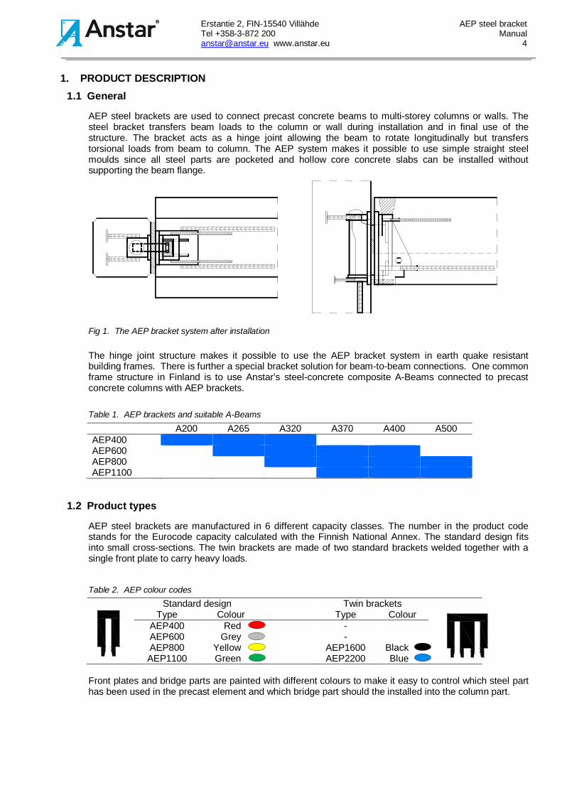
AEP steel brackets are used to connect precast concrete beams to multi-storey columns or walls. Thesteel bracket transfers beam loads to the column or wall during installation and in final use of thestructure. The bracket acts as a hinge joint allowing the beam to rotate longitudinally but transferstorsional loads from beam to column. The AEP system makes it possible to use simple straight steelmoulds since all steel parts are pocketed and hollow core concrete slabs can be installed withoutsupporting the beam flange.
Fig 1. The AEP bracket system after installation
The hinge joint structure makes it possible to use the AEP bracket system in earth quake resistantbuilding frames. There is further a special bracket solution for beam-to-beam connections. One commonframe structure in Finland is to use Anstar’s steel-concrete composite A-Beams connected to precastconcrete columns with AEP brackets.
Table 1. AEP brackets and suitable A-Beams
A200 A265 A320 A370 A400 A500AEP400AEP600AEP800AEP1100
1.2 Product types
AEP steel brackets are manufactured in 6 different capacity classes. The number in the product codestands for the Eurocode capacity calculated with the Finnish National Annex. The standard design fitsinto small cross-sections. The twin brackets are made of two standard brackets welded together with asingle front plate to carry heavy loads.
Table 2. AEP colour codesStandard design Twin brackets
Type Colour Type ColourAEP400 Red -AEP600 Grey -AEP800 Yellow AEP1600 BlackAEP1100 Green AEP2200 Blue
Front plates and bridge parts are painted with different colours to make it easy to control which steel parthas been used in the precast element and which bridge part should the installed into the column part.
Erstantie 2, FIN-15540 Villähde AEP steel bracketTel +358-3-872 200 [email protected] www.anstar.eu 5
AEP-PA
AEP-K
AEP-KL
AEP-PI
500
T12
wedge with aninstallation arm
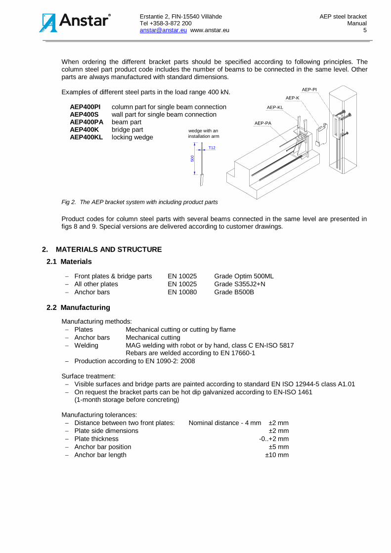
When ordering the different bracket parts should be specified according to following principles. Thecolumn steel part product code includes the number of beams to be connected in the same level. Otherparts are always manufactured with standard dimensions.
Examples of different steel parts in the load range 400 kN.
AEP400PI column part for single beam connectionAEP400S wall part for single beam connectionAEP400PA beam partAEP400K bridge partAEP400KL locking wedge
Fig 2. The AEP bracket system with including product parts
Product codes for column steel parts with several beams connected in the same level are presented infigs 8 and 9. Special versions are delivered according to customer drawings.
2. MATERIALS AND STRUCTURE2.1 Materials
- Front plates & bridge parts EN 10025 Grade Optim 500ML- All other plates EN 10025 Grade S355J2+N- Anchor bars EN 10080 Grade B500B
2.2 Manufacturing
Manufacturing methods:- Plates Mechanical cutting or cutting by flame- Anchor bars Mechanical cutting- Welding MAG welding with robot or by hand, class C EN-ISO 5817
Rebars are welded according to EN 17660-1- Production according to EN 1090-2: 2008
Surface treatment:- Visible surfaces and bridge parts are painted according to standard EN ISO 12944-5 class A1.01- On request the bracket parts can be hot dip galvanized according to EN-ISO 1461
(1-month storage before concreting)
Manufacturing tolerances:- Distance between two front plates: Nominal distance - 4 mm ±2 mm- Plate side dimensions ±2 mm- Plate thickness -0..+2 mm- Anchor bar position ±5 mm- Anchor bar length ±10 mm
Erstantie 2, FIN-15540 Villähde AEP steel bracketTel +358-3-872 200 [email protected] www.anstar.eu 6
2.3 AEP dimensions
2.3.1 AEP-PI column part
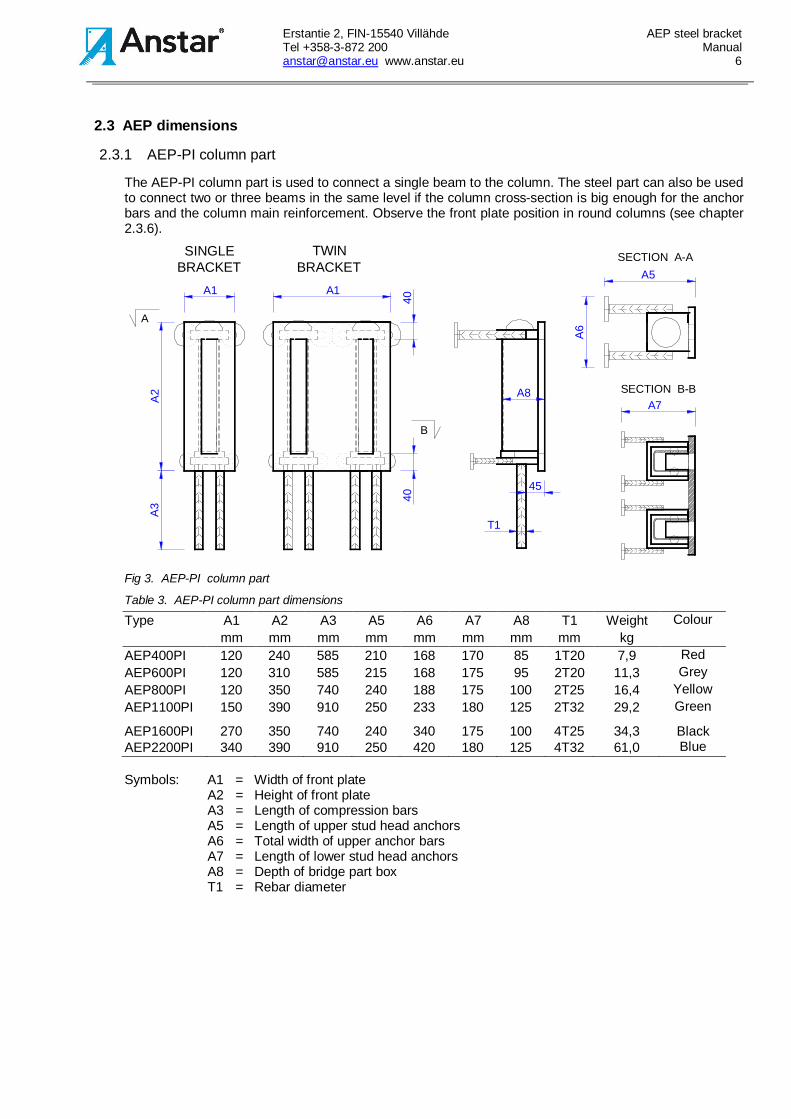
The AEP-PI column part is used to connect a single beam to the column. The steel part can also be usedto connect two or three beams in the same level if the column cross-section is big enough for the anchorbars and the column main reinforcement. Observe the front plate position in round columns (see chapter2.3.6).
A1 A1
A8A2
4040
T1
45
A3
SECTION A-A
A
B
A7
A5
A6
SECTION B-B
TWINBRACKET
SINGLEBRACKET
Fig 3. AEP-PI column part
Table 3. AEP-PI column part dimensions
Type A1 A2 A3 A5 A6 A7 A8 T1 Weight Colourmm mm mm mm mm mm mm mm kg
AEP400PI 120 240 585 210 168 170 85 1T20 7,9 RedAEP600PI 120 310 585 215 168 175 95 2T20 11,3 GreyAEP800PI 120 350 740 240 188 175 100 2T25 16,4 YellowAEP1100PI 150 390 910 250 233 180 125 2T32 29,2 Green
AEP1600PI 270 350 740 240 340 175 100 4T25 34,3 BlackAEP2200PI 340 390 910 250 420 180 125 4T32 61,0 Blue
Symbols: A1 = Width of front plateA2 = Height of front plateA3 = Length of compression barsA5 = Length of upper stud head anchorsA6 = Total width of upper anchor barsA7 = Length of lower stud head anchorsA8 = Depth of bridge part boxT1 = Rebar diameter

Erstantie 2, FIN-15540 Villähde AEP steel bracketTel +358-3-872 200 [email protected] www.anstar.eu 7
2.4 AEP-PA beam part
The AEP-PA beam part can be used in prestressed or reinforced concrete beams.
45
B2
B8
B8
T2
T1
A
B
B9
SECTION B-B B3B4
B7
SECTION A-A
70
T2
T1
TWINBRACKET
SINGLEBRACKET
B1
B2
Fig 4. AEP-PA beam part
Table 4. AEP-PA beam part dimensions
Type B1 B2 B3 B4 B7 B8 B9 T1 T2 Weight Colourmm mm mm mm mm mm mm mm mm kg
AEP400PA 150 215 1025 425 45 58 10 2T12 2T20 12,7 RedAEP600PA 150 275 1035 560 45 58 15 2T16 2T20 18,8 GreyAEP800PA 150 335 1240 670 50 58 20 2T16 2T25 29,2 YellowAEP1100PA 190 380 1240 640 50 73 20 2T16 2T25 39,5 Green
AEP1600PA 300 335 1240 670 50 58 20 4T16 4T25 59,6 BlackAEP2200PA 380 380 1240 640 50 73 20 4T16 4T25 92,5 Blue
Symbols: B1 = Width of front plateB2 = Height of front plateB3 = Length at lower anchor barsB4 = Length at upper anchor barsB7 = Depth of wedge boxB8 = Width of wedge boxB9 = Front plate thicknessT1 = Upper rebar diameterT2 = Lower rebar diameter
Erstantie 2, FIN-15540 Villähde AEP steel bracketTel +358-3-872 200 [email protected] www.anstar.eu 8
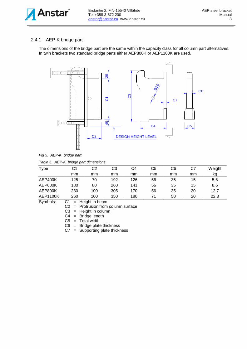
2.4.1 AEP-K bridge part
The dimensions of the bridge part are the same within the capacity class for all column part alternatives.In twin brackets two standard bridge parts either AEP800K or AEP1100K are used.
DESIGN HEIGHT LEVEL
C1
3545
C2
C3
C7
C5
C6
C4
Ø20
Fig 5. AEP-K bridge part
Table 5. AEP-K bridge part dimensions
Type C1 C2 C3 C4 C5 C6 C7 Weightmm mm mm mm mm mm mm kg
AEP400K 125 70 192 126 56 35 15 5,6AEP600K 180 80 260 141 56 35 15 8,6AEP800K 230 100 305 170 56 35 20 12,7AEP1100K 260 100 350 180 71 50 20 22,3Symbols: C1 = Height in beam
C2 = Protrusion from column surfaceC3 = Height in columnC4 = Bridge lengthC5 = Total widthC6 = Bridge plate thicknessC7 = Supporting plate thickness

Erstantie 2, FIN-15540 Villähde AEP steel bracketTel +358-3-872 200 [email protected] www.anstar.eu 9
A5
A6
A7
45
A8
A2A3
40
A1
40
A
B
SECTION B-BSECTION A-A
A5
A740
A1A6
A8
A2A4
40
A3
2.5 AEP-S wall part
The AEP-S wall part is a shorter version of the column standard part that can be installed in concretewalls with a minimum thickness of 180...240 mm. It can also be used in columns with concrete classC25/30 or more.
Fig 6. AEP-S wall part
Table 6. AEP-S wall part dimensions
Type A1 A2 A3 A5 A6 A7 A8 B Weightmm mm mm mm mm mm mm mm kg
AEP400S 120 240 585 150 150 150 85 180 8,5AEP600S 120 310 585 150 150 150 95 180 11,8AEP800S 120 350 740 175 160 175 100 200 17,5AEP1100S 150 390 910 215 190 180 125 240 31,3
2.5.1 AEP-PP part for beam-to-beam connection
The AEP-PP beam-to-beam part is a lower version of the standard column part to be installed in beamsides. The structure makes it possible to connect two equally heigh prefab beams in a perpendicular joint.
Fig 7. AEP-PP beam side part in a beam-to-beam connection
Table 7. Dimensions of AEP-PP beam-to-beam connections
Type A1 A2 A3 A4 A5 A6 A7 A8 A9 Weightmm mm mm mm mm mm mm mm mm kg
AEP400PP 120 240 275 35 210 280 170 85 140 10,9AEP600PP 120 310 360 45 215 310 190 95 155 17,1AEP800PP 120 350 425 70 240 330 190 100 155 24,1AEP1100PP 150 390 490 90 250 385 195 125 190 40,2
Erstantie 2, FIN-15540 Villähde AEP steel bracketTel +358-3-872 200 [email protected] www.anstar.eu 10
Other dimensions as in fig. 3
D1 SECTION A-AIN RECTANGULAR COLUMN
SECTION B-BIN ROUND COLUMN
T1T2
D1 Ø
D1
B
A
E1E2
E1
E2
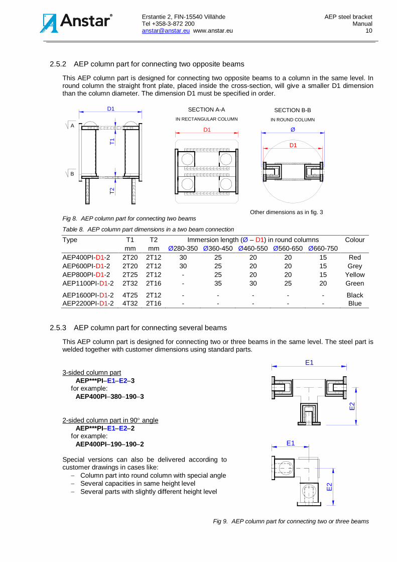
2.5.2 AEP column part for connecting two opposite beams
This AEP column part is designed for connecting two opposite beams to a column in the same level. Inround column the straight front plate, placed inside the cross-section, will give a smaller D1 dimensionthan the column diameter. The dimension D1 must be specified in order.
Fig 8. AEP column part for connecting two beams
Table 8. AEP column part dimensions in a two beam connection
Type T1 T2 Immersion length (Ø – D1) in round columns Colourmm mm Ø280-350 Ø360-450 Ø460-550 Ø560-650 Ø660-750
AEP400PI-D1-2 2T20 2T12 30 25 20 20 15 RedAEP600PI-D1-2 2T20 2T12 30 25 20 20 15 GreyAEP800PI-D1-2 2T25 2T12 - 25 20 20 15 YellowAEP1100PI-D1-2 2T32 2T16 - 35 30 25 20 Green
AEP1600PI-D1-2 4T25 2T12 - - - - - BlackAEP2200PI-D1-2 4T32 2T16 - - - - - Blue
2.5.3 AEP column part for connecting several beams
This AEP column part is designed for connecting two or three beams in the same level. The steel part iswelded together with customer dimensions using standard parts.
3-sided column partAEP***PI-E1-E2-3
for example:AEP400PI-380-190-3
2-sided column part in 90° angleAEP***PI-E1-E2-2
for example:AEP400PI-190-190-2
Special versions can also be delivered according tocustomer drawings in cases like:
- Column part into round column with special angle- Several capacities in same height level- Several parts with slightly different height level
Fig 9. AEP column part for connecting two or three beams
Erstantie 2, FIN-15540 Villähde AEP steel bracketTel +358-3-872 200 [email protected] www.anstar.eu 11
N
3. QUALITY CONTROL AND MARKINGAnstar Oy has a quality control agreement with Inspecta Certification and Nordcert. The shoe productionis certified according to standards EN 1090-1, EN 3834-2 and EN 17660-1.
Steel brackets are manufactured with following markings:- control mark for Inspecta Certification and Nordcert- company name ANSTAR, CE-mark, product type and week of manufacture
4. CONNECTION DESIGN4.1 Basis of design
The AEP bracket connection is designed according to:- EN 1993-1-1 Eurocode 3: Design of steel structures – general rules- EN 1993-1-8 Eurocode 3: Design of steel structures – joints- EN 1992-1-1 Eurocode 2: Design of concrete structures – general rules
Concrete C40/50, other than good bond conditions (EN 1992-1-1: 8.4):γc = 1,5 γs = 1,15 rebars γs = 1,0 platesα3 = 0,7 α6 = 1,0 α1 = α2 = α4 = α5 = 1,0η1 = 1,0 η2 = 1,0
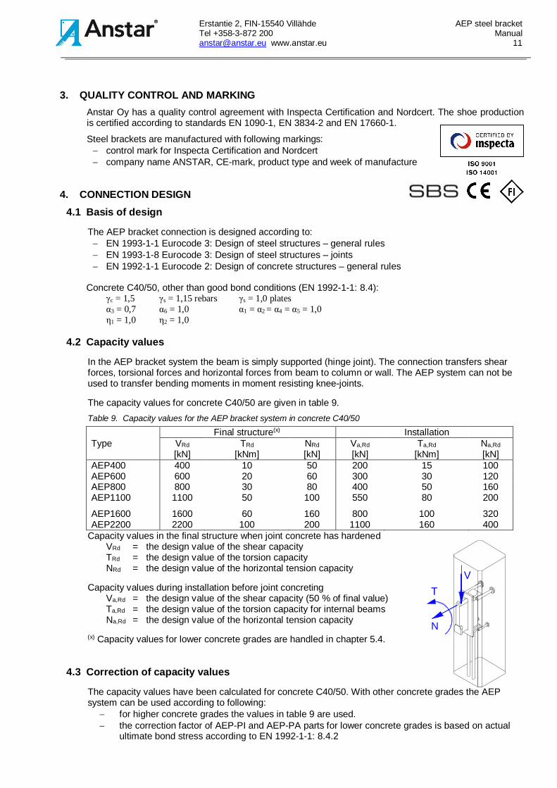
4.2 Capacity values
In the AEP bracket system the beam is simply supported (hinge joint). The connection transfers shearforces, torsional forces and horizontal forces from beam to column or wall. The AEP system can not beused to transfer bending moments in moment resisting knee-joints.
The capacity values for concrete C40/50 are given in table 9.Table 9. Capacity values for the AEP bracket system in concrete C40/50
Final structure(x) InstallationType VRd
[kN]TRd
[kNm]NRd
[kN]Va,Rd
[kN]Ta,Rd
[kNm]Na,Rd
[kN]AEP400 400 10 50 200 15 100AEP600 600 20 60 300 30 120AEP800 800 30 80 400 50 160AEP1100 1100 50 100 550 80 200
AEP1600 1600 60 160 800 100 320AEP2200 2200 100 200 1100 160 400
Capacity values in the final structure when joint concrete has hardenedVRd = the design value of the shear capacityTRd = the design value of the torsion capacityNRd = the design value of the horizontal tension capacity
Capacity values during installation before joint concretingVa,Rd = the design value of the shear capacity (50 % of final value)Ta,Rd = the design value of the torsion capacity for internal beamsNa,Rd = the design value of the horizontal tension capacity
(x) Capacity values for lower concrete grades are handled in chapter 5.4.
4.3 Correction of capacity values
The capacity values have been calculated for concrete C40/50. With other concrete grades the AEPsystem can be used according to following:
- for higher concrete grades the values in table 9 are used.- the correction factor of AEP-PI and AEP-PA parts for lower concrete grades is based on actual
ultimate bond stress according to EN 1992-1-1: 8.4.2
Erstantie 2, FIN-15540 Villähde AEP steel bracketTel +358-3-872 200 [email protected] www.anstar.eu 12
n = fbd dim / fbd C40/50 < 1,0- The wall part (fig 6) can be used without capacity reduction for concrete grades ≥ C25/30.
4.4 Design instructions
4.4.1 Bracket position in a column-to-beam joint
1. Concrete frame It is recommended that the lower end of the beam part front plate is positioned in the same level as the
beam lower surface, the lower end of the column part front plate will then also be in the same level asthe beam lower surface. In high beams the bracket will be positioned higher so that the bridge partupper level is in the same level with the hollow core slabs. This way the beam hinge joint can rotate atan optimal height level. The joint between the beam and the column must allow the beam end to rotatevertically on the bridge support.
2. Bracket with the composite A-Beam With composite A-Beams the lower end of the column part front plate will be in the same level with
lower surface of the hollow core deck slabs. More instructions can be found in the A-Beam productmanual.
4.4.2 Design of hollow core slabs
1. Deck stability The slab elements are tied together to a monolithic floor unit by placing reinforcement in the slab
joints. The bracket system cannot be used to tie the slabs together, the tying rebars must be anchoredto the other side of the bracket joint. The horizontal load capacity has been determined only forinstallation loads and accidental loads on the final structure.
2. Joint between beam and hollow core slabs After hardening of the concrete the joint reinforcement will tie the slabs and beam together and the live
load cannot therefore add to the beam torsion load. The bracket joint must still be analyzed also forthe live load.
4.4.3 Checking load capacities
The load capacities given in table 9 are checked in the following manner:
1. Beam shear loadThe bridge part will transfer the shear load VEd to the column. The bracket type is chosen so that thedesign shear load VEd will not exceed the given capacity VRd.
2. Beam horizontal loadThe horizontal load capacity NRd has been determined for extraordinary tension loads duringinstallation and accidental loads on the final structure. The AEP bracket system can transferextraordinary horizontal loads also without tie reinforcement and joint concreting but cannot be used toreplace the tie reinforcement.
3. Beam torsionUnsymmetrical beam loading will cause torsion that is transferred to the column. The design torsionload TEd must not exceed the given capacity TRd. The torsion capacity Ta,Rd during installation hasbeen raised by restricting the shear capacity to 50 % of the maximum value. This added capacity canbe used only for temporary, unsymmetrical installation loads of internal beams. This torsion will beeliminated in the final structure. In edge beams the installation torsion load has to be carried also bythe final structure and therefore the added torsion load cannot be used.
The beam twisting caused by moving live loads has been considered as a constraint action. This loadcase must be analyzed for unsymmetrical live loads and/or long and slender structures. The torsionload capacity can be added by reducing the shear load (see table 9). The ductile joint behaviour inlimit state is secured by using reinforcement according to principles described in chapter 5.3.
4. Combined loadsThe combined load effect need not be analyzed. The design criteria is that no singular given capacityis exceeded.
4.4.4 Installation
Erstantie 2, FIN-15540 Villähde AEP steel bracketTel +358-3-872 200 [email protected] www.anstar.eu 13
1. CapacitiesThe checking of capacities is done in the same manner as for the final structure. For internal beams itis possible during installation to use bigger torsion and horizontal load capacities by using only 50% ofthe shear load capacity.
2. Assembly supportsThere is no need for supporting the beam flange during one sided slab installation as long as thetorsion capacity is not exceeded.
3. Assembly toleranceThe bridge part is provided with a nose so, that the beam must be lifted 35 mm to get it off thebridge. The AEP steel part dimensions allow a longitudinal beam movement ±15 mm and a twist±1.5 degrees around the longitudinal axis. This clearance is taken away by wedging the beam part tothe bridge part before installation of slab elements.
4.5 Design of beams and columns
4.5.1 Beam design
1. Beam span and bendingThe support is situated on the inner side of the beam part front plate. The span length is determinedby the distance between the column surfaces from which the distance 2*e1 is subtracted when thejoint between the column and the beam is 20 mm (fig 13). The precast beam is designed for bendingas a simply supported beam using the above mentioned span length. The main reinforcement isanchored to the beam end according to standard principles for rectangular beams and the steel partlower rebars are anchored to this main reinforcement.
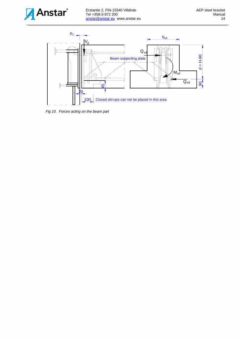
2. Beam end shear capacityThe beam support reaction is acting on the lower support plate, which is situated 90 mm above thebeam lower surface. The plate size has been determined so, that the shear load causes the concretecompression stress fcd. The support reaction is transferred from the horizontal plate to the bridge partvia the front plate. The effective beam cross-section is situated above the support plate. The beameffective height is d=H-90 mm and the effective width is beff. The shear reinforcement is determinedaccording to principles for rectangular concrete beams (fig 10). If the bracket is positioned higher upin the beam then the shear capacity and the shear reinforcement should be designed using methodsdeveloped for recessed beam ends.
3. TorsionThe AEP bracket system transfers the beam torsion to the column. If beam minimum widthdimensions according to table 11 in chapter 5.2 and torsion reinforcement according to chapter 5.3.2are used then there is no further need to analyze the internal torsion forces acting in the beam end.The reinforcement is designed according to standard methods developed for rectangular concretebeams. Longitudinal torsion rebars must be taken to beam end and anchored using U-formedvertical links.
When designing stirrups it should be noticed that closed stirrups can be used only beginning at 100mm from the beam end because of the bridge opening.
Erstantie 2, FIN-15540 Villähde AEP steel bracketTel +358-3-872 200 [email protected] www.anstar.eu 14
Closed stirrups can not be placed in this area
V
1
d
eff
Beam supporting plate
Qvd
Mvd
Qvd
20
100
90d
=H
-90
be
45
Fig 10. Forces acting on the beam part
Erstantie 2, FIN-15540 Villähde AEP steel bracketTel +358-3-872 200 [email protected] www.anstar.eu 15
P1
1e = 45-55 mm
QEd
VEd
EdQ
MEd
EydQ
QEyd
MEyd
Beam lower surfaceP1
H
VEd
4.5.2 Column design
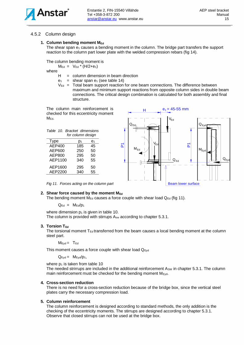
1. Column bending moment MEdThe shear span e1 causes a bending moment in the column. The bridge part transfers the supportreaction to the column part lower plate with the welded compression rebars (fig 14).
The column bending moment isMEd = VEd * (H/2+e1)
whereH = column dimension in beam directione1 = shear span e1 (see table 14)VEd = Total beam support reaction for one beam connections. The difference between
maximum and minimum support reactions from opposite column sides in double beamconnections. The critical design combination is calculated for both assembly and finalstructure.
The column main reinforcement ischecked for this eccentricity momentMEd.
Table 10. Bracket dimensionsfor column design
Type p1 e1
AEP400 185 45AEP600 250 50AEP800 295 50AEP1100 340 55
AEP1600 295 50AEP2200 340 55
Fig 11. Forces acting on the column part
2. Shear force caused by the moment MEdThe bending moment MEd causes a force couple with shear load QEd (fig 11).
QEd = MEd/p1
where dimension p1 is given in table 10.The column is provided with stirrups Asw according to chapter 5.3.1.
3. Torsion TEdThe torsional moment TEd transferred from the beam causes a local bending moment at the columnsteel part.
MEyd = TEd
This moment causes a force couple with shear load QEyd
QEyd = MEyd/p1,
where p1 is taken from table 10The needed strirrups are included in the additional reinforcement ASW in chapter 5.3.1. The columnmain reinforcement must be checked for the bending moment MEyd.
4. Cross-section reductionThere is no need for a cross-section reduction because of the bridge box, since the vertical steelplates carry the necessary compression load.
5. Column reinforcementThe column reinforcement is designed according to standard methods, the only addition is thechecking of the eccentricity moments. The stirrups are designed according to chapter 5.3.1.Observe that closed stirrups can not be used at the bridge box.
Erstantie 2, FIN-15540 Villähde AEP steel bracketTel +358-3-872 200 [email protected] www.anstar.eu 16
5. USING THE AEP BRACKET5.1 Limitations on use
The capacities have been determined for static loads only. Dynamic loads should be designed withbigger safety factors and the functioning of the different parts should be analyzed in each project.
The AEP bracket system can be used in precast concrete framed structures and with compositeconcrete-steel columns and the Anstar composite A-Beam. The use of the AEP bracket system togetherwith other composite or steel beams must be examined in each case.
The bracket system can not be used in moment resisting connections and the bracket should always bedesigned in such a manner that no fixing moments are transferred. The joint between the beam and thecolumn must allow the beam end to rotate vertically on the bridge support.
The use of the given capacity values requires that the assembly tolerances are according to chapter 6.4and that the additional reinforcement is according to chapter 5.3.
5.2 Minimum structural dimensions
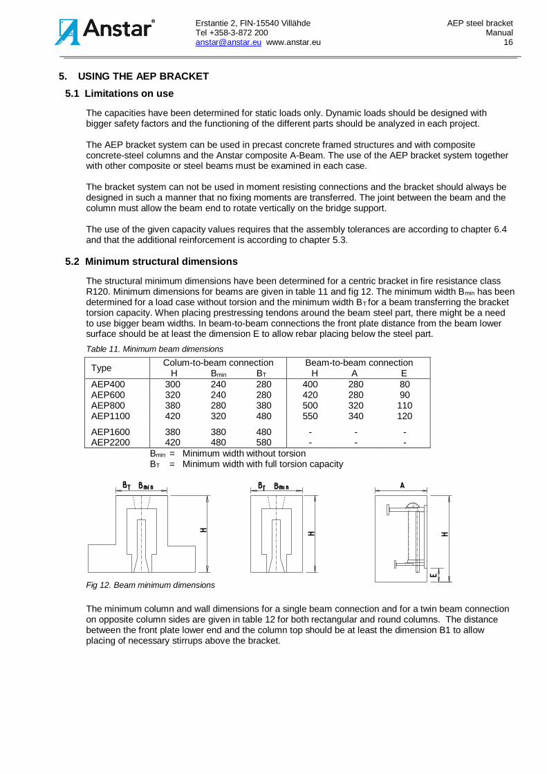
The structural minimum dimensions have been determined for a centric bracket in fire resistance classR120. Minimum dimensions for beams are given in table 11 and fig 12. The minimum width Bmin has beendetermined for a load case without torsion and the minimum width BT for a beam transferring the brackettorsion capacity. When placing prestressing tendons around the beam steel part, there might be a needto use bigger beam widths. In beam-to-beam connections the front plate distance from the beam lowersurface should be at least the dimension E to allow rebar placing below the steel part.Table 11. Minimum beam dimensions
Type Colum-to-beam connectionH Bmin BT
Beam-to-beam connectionH A E
AEP400 300 240 280 400 280 80AEP600 320 240 280 420 280 90AEP800 380 280 380 500 320 110AEP1100 420 320 480 550 340 120
AEP1600 380 380 480 - - -AEP2200 420 480 580 - - -
Bmin = Minimum width without torsionBT = Minimum width with full torsion capacity
Fig 12. Beam minimum dimensions
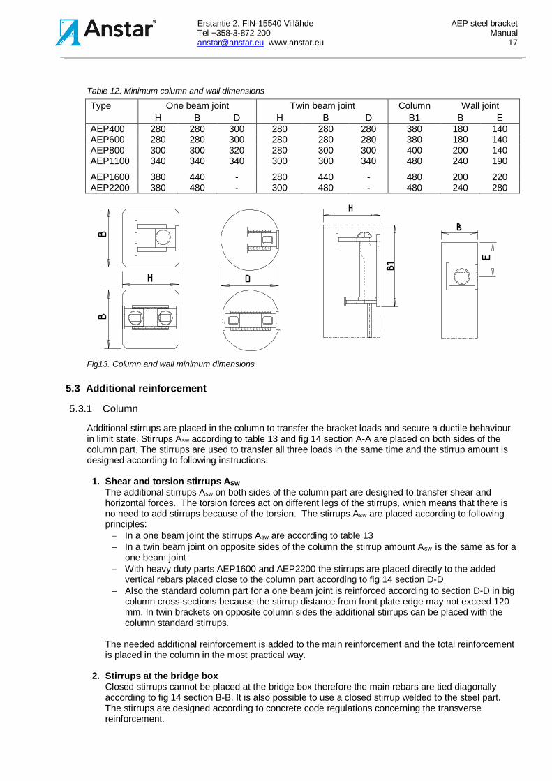
The minimum column and wall dimensions for a single beam connection and for a twin beam connectionon opposite column sides are given in table 12 for both rectangular and round columns. The distancebetween the front plate lower end and the column top should be at least the dimension B1 to allowplacing of necessary stirrups above the bracket.
Erstantie 2, FIN-15540 Villähde AEP steel bracketTel +358-3-872 200 [email protected] www.anstar.eu 17
Table 12. Minimum column and wall dimensions
Type One beam joint Twin beam joint Column Wall jointH B D H B D B1 B E
AEP400 280 280 300 280 280 280 380 180 140AEP600 280 280 300 280 280 280 380 180 140AEP800 300 300 320 280 300 300 400 200 140AEP1100 340 340 340 300 300 340 480 240 190
AEP1600 380 440 - 280 440 - 480 200 220AEP2200 380 480 - 300 480 - 480 240 280
Fig13. Column and wall minimum dimensions
5.3 Additional reinforcement
5.3.1 Column
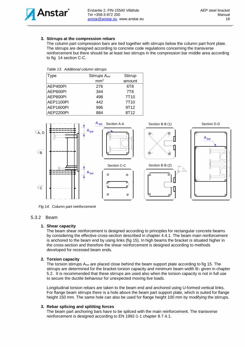
Additional stirrups are placed in the column to transfer the bracket loads and secure a ductile behaviourin limit state. Stirrups Asw according to table 13 and fig 14 section A-A are placed on both sides of thecolumn part. The stirrups are used to transfer all three loads in the same time and the stirrup amount isdesigned according to following instructions:
1. Shear and torsion stirrups ASWThe additional stirrups Asw on both sides of the column part are designed to transfer shear andhorizontal forces. The torsion forces act on different legs of the stirrups, which means that there isno need to add stirrups because of the torsion. The stirrups Asw are placed according to followingprinciples:- In a one beam joint the stirrups Asw are according to table 13- In a twin beam joint on opposite sides of the column the stirrup amount Asw is the same as for a
one beam joint- With heavy duty parts AEP1600 and AEP2200 the stirrups are placed directly to the added
vertical rebars placed close to the column part according to fig 14 section D-D- Also the standard column part for a one beam joint is reinforced according to section D-D in big
column cross-sections because the stirrup distance from front plate edge may not exceed 120mm. In twin brackets on opposite column sides the additional stirrups can be placed with thecolumn standard stirrups.
The needed additional reinforcement is added to the main reinforcement and the total reinforcementis placed in the column in the most practical way.
2. Stirrups at the bridge boxClosed stirrups cannot be placed at the bridge box therefore the main rebars are tied diagonallyaccording to fig 14 section B-B. It is also possible to use a closed stirrup welded to the steel part.The stirrups are designed according to concrete code regulations concerning the transversereinforcement.
Erstantie 2, FIN-15540 Villähde AEP steel bracketTel +358-3-872 200 [email protected] www.anstar.eu 18
3. Stirrups at the compression rebarsThe column part compression bars are tied together with stirrups below the column part front plate.The stirrups are designed according to concrete code regulations concerning the transversereinforcement but there should be at least two stirrups in the compression bar middle area accordingto fig 14 section C-C.
Table 13. Additional column stirrups
Type Stirrups Asw Stirrupmm2 amount
AEP400PI 276 6T8AEP600PI 344 7T8AEP800PI 498 7T10AEP1100PI 442 7T10AEP1600PI 996 9T12AEP2200PI 884 8T12
swA
swAswA
Section D-D
A
A, D
Section B-B (2)
Section A-A
sw
B
C
Section B-B (1)
Section C-C
Fig 14. Column part reinforcement
5.3.2 Beam
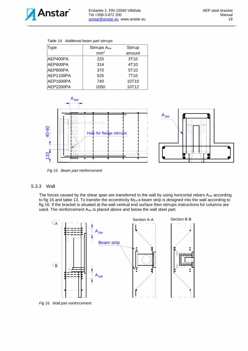
1. Shear capacityThe beam shear reinforcement is designed according to principles for rectangular concrete beamsby considering the effective cross-section described in chapter 4.4.1. The beam main reinforcementis anchored to the beam end by using links (fig 15). In high beams the bracket is situated higher inthe cross-section and therefore the shear reinforcement is designed according to methodsdeveloped for recessed beam ends.
2. Torsion capacityThe torsion stirrups Asw are placed close behind the beam support plate according to fig 15. Thestirrups are determined for the bracket torsion capacity and minimum beam width BT given in chapter5.2. It is recommended that these stirrups are used also when the torsion capacity is not in full useto secure the ductile behaviour for unexpected moving live loads.
Longitudinal torsion rebars are taken to the beam end and anchored using U-formed vertical links.For flange beam stirrups there is a hole above the beam part support plate, which is suited for flangeheight 150 mm. The same hole can also be used for flange height 100 mm by modifying the stirrups.
3. Rebar splicing and splitting forcesThe beam part anchoring bars have to be spliced with the main reinforcement. The transversereinforcement is designed according to EN 1992-1-1 chapter 8.7.4.1.
Erstantie 2, FIN-15540 Villähde AEP steel bracketTel +358-3-872 200 [email protected] www.anstar.eu 19
Table 14. Additional beam part stirrups
Type Stirrups Asw Stirrupmm2 amount
AEP400PA 220 3T10AEP600PA 314 4T10AEP800PA 370 5T10AEP1100PA 525 7T10AEP1600PA 740 10T10AEP2200PA 1050 10T12
Hole for flange stirrups
swA
swA
110
40-6
0
Fig 15. Beam part reinforcement
5.3.3 Wall
The forces caused by the shear span are transferred to the wall by using horizontal rebars Asw accordingto fig 16 and table 13. To transfer the eccentricity MEd a beam strip is designed into the wall according tofig 16. If the bracket is situated at the wall vertical end surface then stirrups instructions for columns areused. The reinforcement Asw is placed above and below the wall steel part.
Section B-B
B
A
swA
swA
Beam strip
Section A-A
Fig 16. Wall part reinforcement
Erstantie 2, FIN-15540 Villähde AEP steel bracketTel +358-3-872 200 [email protected] www.anstar.eu 20
5.3.4 Beam-to-beam connection
In beam-to-beam connections the beam part AEP-PA is reinforced as in fig 15. The ’column’ part AEP-PPin the main beam is reinforced according to fig 17 and table 13. The additional reinforcement Asw isplaced on both sides of the steel part. Extra stirrups are placed close to the upper stud anchors toprevent concrete cone failure. High wall like beams can also be reinforced according to fig 16. The mainbeam shear force has to be considered as for standard point loaded rectangular concrete beams.
DESIGN HEIGHT LEVELswA swA
Fig 17. Beam-to-beam joint reinforcement
5.4 Fire protection
The AEP bracket steel parts are cast into concrete, which protects against fire. The rebar concrete coveris at least 45 mm, which corresponds to fire resistance class R120. On request the AEP column partrebars can be placed with a bigger concrete cover for resistance class R180. The beam part open endand the bridge box require a fire protection according to instructions in chapter 6.5.
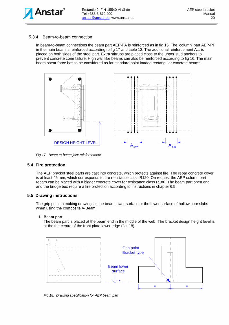
5.5 Drawing instructions
The grip point in making drawings is the beam lower surface or the lower surface of hollow core slabswhen using the composite A-Beam.
1. Beam partThe beam part is placed at the beam end in the middle of the web. The bracket design height level isat the the centre of the front plate lower edge (fig 18).
+
= =
Beam lowersurface
Grip pointBracket type
Fig 18. Drawing specification for AEP beam part
Erstantie 2, FIN-15540 Villähde AEP steel bracketTel +358-3-872 200 [email protected] www.anstar.eu 21
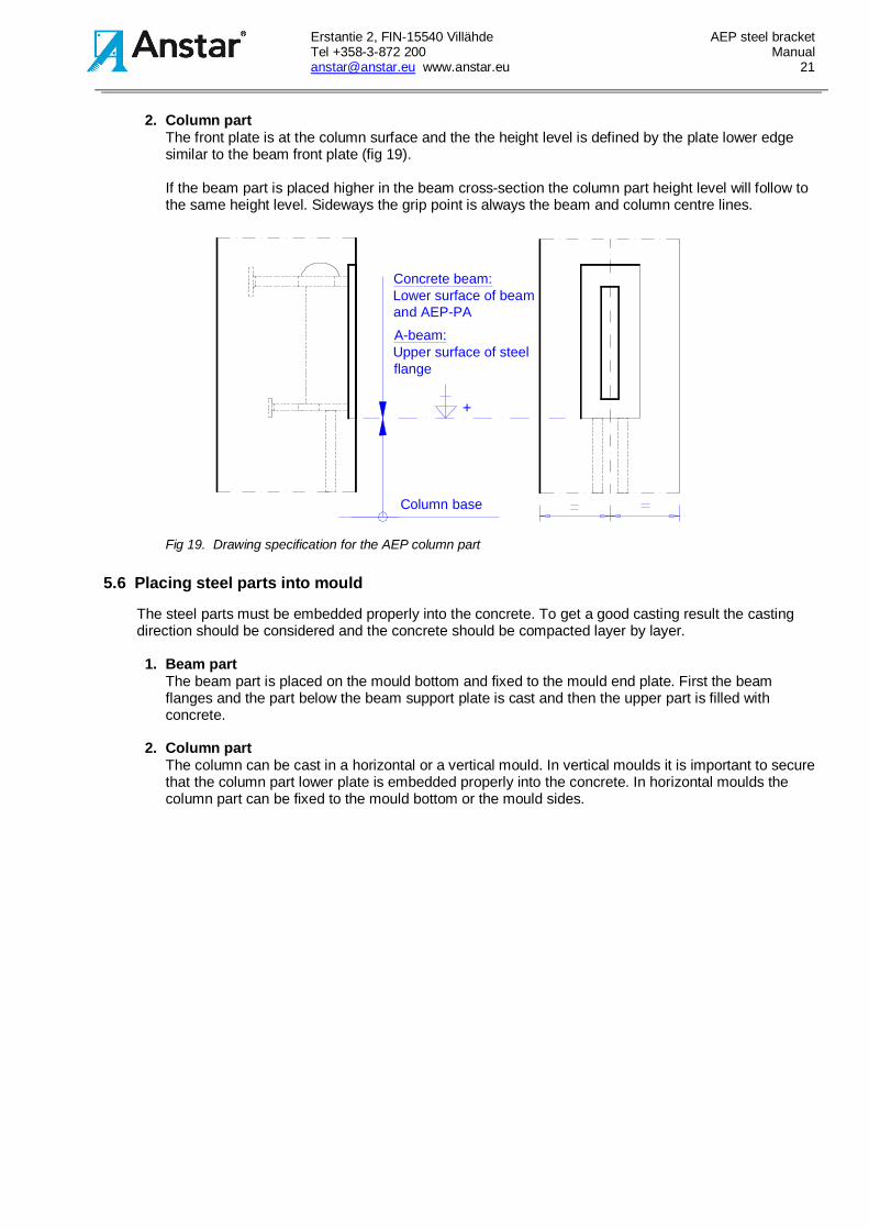
2. Column partThe front plate is at the column surface and the the height level is defined by the plate lower edgesimilar to the beam front plate (fig 19).
If the beam part is placed higher in the beam cross-section the column part height level will follow tothe same height level. Sideways the grip point is always the beam and column centre lines.
Column base
+
Concrete beam:Lower surface of beamand AEP-PA
A-beam:Upper surface of steelflange
Fig 19. Drawing specification for the AEP column part
5.6 Placing steel parts into mould
The steel parts must be embedded properly into the concrete. To get a good casting result the castingdirection should be considered and the concrete should be compacted layer by layer.
1. Beam partThe beam part is placed on the mould bottom and fixed to the mould end plate. First the beamflanges and the part below the beam support plate is cast and then the upper part is filled withconcrete.
2. Column partThe column can be cast in a horizontal or a vertical mould. In vertical moulds it is important to securethat the column part lower plate is embedded properly into the concrete. In horizontal moulds thecolumn part can be fixed to the mould bottom or the mould sides.
Erstantie 2, FIN-15540 Villähde AEP steel bracketTel +358-3-872 200 [email protected] www.anstar.eu 22
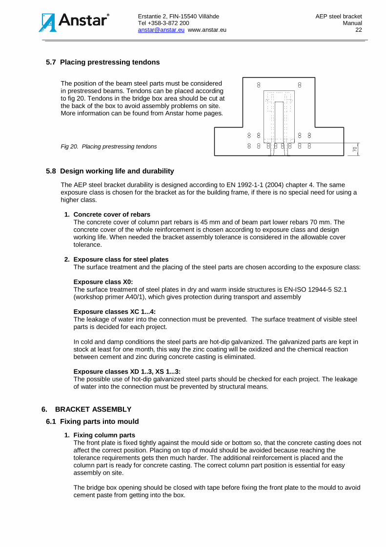
5.7 Placing prestressing tendons
The position of the beam steel parts must be consideredin prestressed beams. Tendons can be placed accordingto fig 20. Tendons in the bridge box area should be cut atthe back of the box to avoid assembly problems on site.More information can be found from Anstar home pages.
Fig 20. Placing prestressing tendons
5.8 Design working life and durability
The AEP steel bracket durability is designed according to EN 1992-1-1 (2004) chapter 4. The sameexposure class is chosen for the bracket as for the building frame, if there is no special need for using ahigher class.
1. Concrete cover of rebarsThe concrete cover of column part rebars is 45 mm and of beam part lower rebars 70 mm. Theconcrete cover of the whole reinforcement is chosen according to exposure class and designworking life. When needed the bracket assembly tolerance is considered in the allowable covertolerance.
2. Exposure class for steel platesThe surface treatment and the placing of the steel parts are chosen according to the exposure class:
Exposure class X0:The surface treatment of steel plates in dry and warm inside structures is EN-ISO 12944-5 S2.1(workshop primer A40/1), which gives protection during transport and assembly
Exposure classes XC 1...4:The leakage of water into the connection must be prevented. The surface treatment of visible steelparts is decided for each project.
In cold and damp conditions the steel parts are hot-dip galvanized. The galvanized parts are kept instock at least for one month, this way the zinc coating will be oxidized and the chemical reactionbetween cement and zinc during concrete casting is eliminated.
Exposure classes XD 1..3, XS 1...3:The possible use of hot-dip galvanized steel parts should be checked for each project. The leakageof water into the connection must be prevented by structural means.
6. BRACKET ASSEMBLY6.1 Fixing parts into mould
1. Fixing column partsThe front plate is fixed tightly against the mould side or bottom so, that the concrete casting does notaffect the correct position. Placing on top of mould should be avoided because reaching thetolerance requirements gets then much harder. The additional reinforcement is placed and thecolumn part is ready for concrete casting. The correct column part position is essential for easyassembly on site.
The bridge box opening should be closed with tape before fixing the front plate to the mould to avoidcement paste from getting into the box.
Erstantie 2, FIN-15540 Villähde AEP steel bracketTel +358-3-872 200 [email protected] www.anstar.eu 23
2. Fixing beam partsThe front plate is placed on the mould bottom and fixed tightly against the mould end plate so, thatthe correct position is kept during the concrete casting. Steel parts in correct position are essentialfor easy assembly on site.
Above the beam part a recess should be made for the wedging. The recess bottom should be atleast the same size as the wedge box opening and the sides should become wider upwards to makethe wedge assembly easy. When needed assembly parts can be welded to the steel plates. Thetendon opening at the back of the bridge box is closed in a suitable manner.
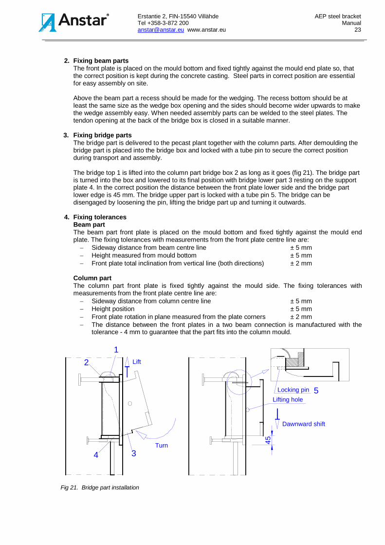
3. Fixing bridge partsThe bridge part is delivered to the pecast plant together with the column parts. After demoulding thebridge part is placed into the bridge box and locked with a tube pin to secure the correct positionduring transport and assembly.
The bridge top 1 is lifted into the column part bridge box 2 as long as it goes (fig 21). The bridge partis turned into the box and lowered to its final position with bridge lower part 3 resting on the supportplate 4. In the correct position the distance between the front plate lower side and the bridge partlower edge is 45 mm. The bridge upper part is locked with a tube pin 5. The bridge can bedisengaged by loosening the pin, lifting the bridge part up and turning it outwards.
4. Fixing tolerancesBeam partThe beam part front plate is placed on the mould bottom and fixed tightly against the mould endplate. The fixing tolerances with measurements from the front plate centre line are:- Sideway distance from beam centre line ± 5 mm- Height measured from mould bottom ± 5 mm- Front plate total inclination from vertical line (both directions) ± 2 mm
Column partThe column part front plate is fixed tightly against the mould side. The fixing tolerances withmeasurements from the front plate centre line are:- Sideway distance from column centre line ± 5 mm- Height position ± 5 mm- Front plate rotation in plane measured from the plate corners ± 2 mm- The distance between the front plates in a two beam connection is manufactured with the
tolerance - 4 mm to guarantee that the part fits into the column mould.
Turn34
1Lift2
5
Dawnward shift
Locking pinLifting hole
45
Fig 21. Bridge part installation
Erstantie 2, FIN-15540 Villähde AEP steel bracketTel +358-3-872 200 [email protected] www.anstar.eu 24
6.2 Assembly on site
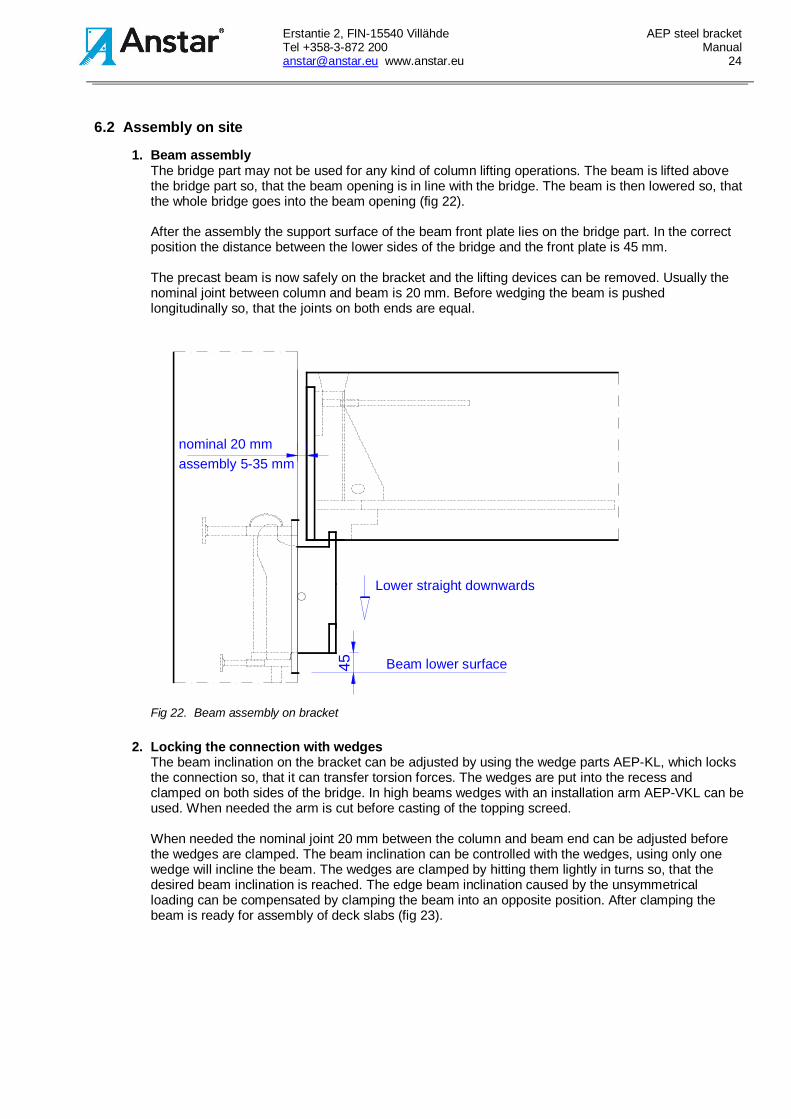
1. Beam assemblyThe bridge part may not be used for any kind of column lifting operations. The beam is lifted abovethe bridge part so, that the beam opening is in line with the bridge. The beam is then lowered so, thatthe whole bridge goes into the beam opening (fig 22).
After the assembly the support surface of the beam front plate lies on the bridge part. In the correctposition the distance between the lower sides of the bridge and the front plate is 45 mm.
The precast beam is now safely on the bracket and the lifting devices can be removed. Usually thenominal joint between column and beam is 20 mm. Before wedging the beam is pushedlongitudinally so, that the joints on both ends are equal.
assembly 5-35 mm
Lower straight downwards
nominal 20 mm
45 Beam lower surface
Fig 22. Beam assembly on bracket
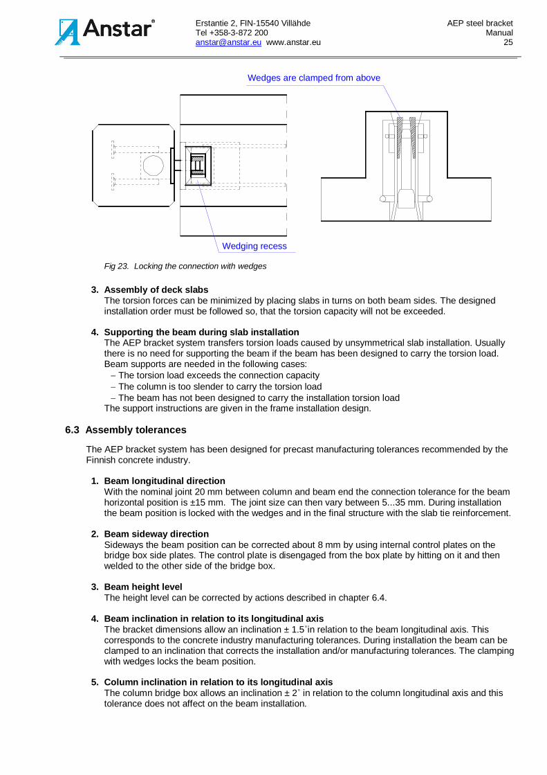
2. Locking the connection with wedgesThe beam inclination on the bracket can be adjusted by using the wedge parts AEP-KL, which locksthe connection so, that it can transfer torsion forces. The wedges are put into the recess andclamped on both sides of the bridge. In high beams wedges with an installation arm AEP-VKL can beused. When needed the arm is cut before casting of the topping screed.
When needed the nominal joint 20 mm between the column and beam end can be adjusted beforethe wedges are clamped. The beam inclination can be controlled with the wedges, using only onewedge will incline the beam. The wedges are clamped by hitting them lightly in turns so, that thedesired beam inclination is reached. The edge beam inclination caused by the unsymmetricalloading can be compensated by clamping the beam into an opposite position. After clamping thebeam is ready for assembly of deck slabs (fig 23).
Erstantie 2, FIN-15540 Villähde AEP steel bracketTel +358-3-872 200 [email protected] www.anstar.eu 25
Wedges are clamped from above
Wedging recess
Fig 23. Locking the connection with wedges
3. Assembly of deck slabsThe torsion forces can be minimized by placing slabs in turns on both beam sides. The designedinstallation order must be followed so, that the torsion capacity will not be exceeded.
4. Supporting the beam during slab installationThe AEP bracket system transfers torsion loads caused by unsymmetrical slab installation. Usuallythere is no need for supporting the beam if the beam has been designed to carry the torsion load.Beam supports are needed in the following cases:- The torsion load exceeds the connection capacity- The column is too slender to carry the torsion load- The beam has not been designed to carry the installation torsion load
The support instructions are given in the frame installation design.
6.3 Assembly tolerances
The AEP bracket system has been designed for precast manufacturing tolerances recommended by theFinnish concrete industry.
1. Beam longitudinal directionWith the nominal joint 20 mm between column and beam end the connection tolerance for the beamhorizontal position is ±15 mm. The joint size can then vary between 5...35 mm. During installationthe beam position is locked with the wedges and in the final structure with the slab tie reinforcement.
2. Beam sideway directionSideways the beam position can be corrected about 8 mm by using internal control plates on thebridge box side plates. The control plate is disengaged from the box plate by hitting on it and thenwelded to the other side of the bridge box.
3. Beam height levelThe height level can be corrected by actions described in chapter 6.4.
4. Beam inclination in relation to its longitudinal axisThe bracket dimensions allow an inclination ± 1.5˚in relation to the beam longitudinal axis. Thiscorresponds to the concrete industry manufacturing tolerances. During installation the beam can beclamped to an inclination that corrects the installation and/or manufacturing tolerances. The clampingwith wedges locks the beam position.
5. Column inclination in relation to its longitudinal axisThe column bridge box allows an inclination ± 2˚ in relation to the column longitudinal axis and thistolerance does not affect on the beam installation.
Erstantie 2, FIN-15540 Villähde AEP steel bracketTel +358-3-872 200 [email protected] www.anstar.eu 26
6.4 Actions when tolerances are exceeded
1. Beam longitudinal toleranceIf the beam longitudinal tolerance is exceeded the only way to correct the situation is to manufacturea longer bridge part, which means that the capacity values must be checked with new calculations.
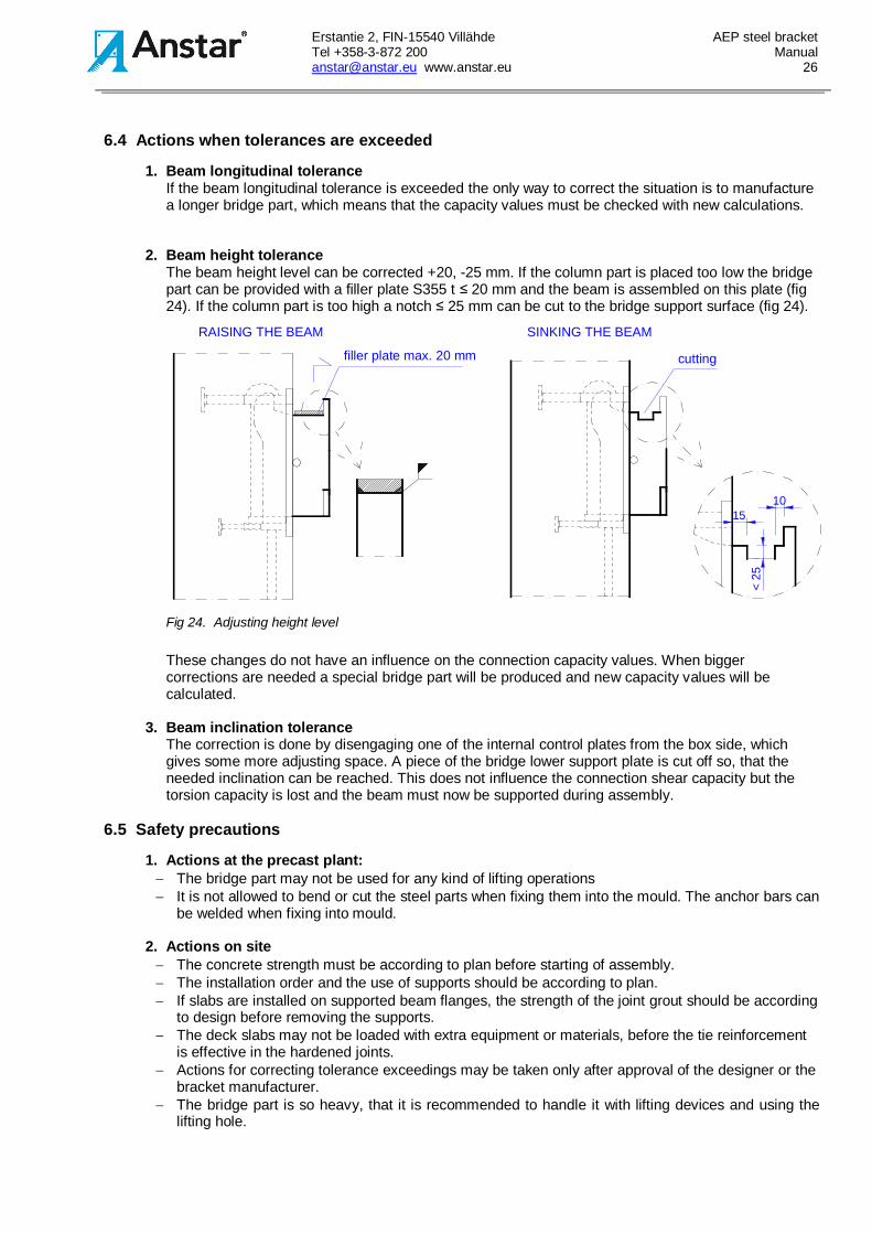
2. Beam height toleranceThe beam height level can be corrected +20, -25 mm. If the column part is placed too low the bridgepart can be provided with a filler plate S355 t ≤ 20 mm and the beam is assembled on this plate (fig24). If the column part is too high a notch ≤ 25 mm can be cut to the bridge support surface (fig 24).
<25
RAISING THE BEAM SINKING THE BEAM
filler plate max. 20 mm cutting
1510
Fig 24. Adjusting height level
These changes do not have an influence on the connection capacity values. When biggercorrections are needed a special bridge part will be produced and new capacity values will becalculated.
3. Beam inclination toleranceThe correction is done by disengaging one of the internal control plates from the box side, whichgives some more adjusting space. A piece of the bridge lower support plate is cut off so, that theneeded inclination can be reached. This does not influence the connection shear capacity but thetorsion capacity is lost and the beam must now be supported during assembly.
6.5 Safety precautions
1. Actions at the precast plant:- The bridge part may not be used for any kind of lifting operations- It is not allowed to bend or cut the steel parts when fixing them into the mould. The anchor bars can
be welded when fixing into mould.
2. Actions on site- The concrete strength must be according to plan before starting of assembly.- The installation order and the use of supports should be according to plan.- If slabs are installed on supported beam flanges, the strength of the joint grout should be according
to design before removing the supports.- The deck slabs may not be loaded with extra equipment or materials, before the tie reinforcement
is effective in the hardened joints.- Actions for correcting tolerance exceedings may be taken only after approval of the designer or the
bracket manufacturer.- The bridge part is so heavy, that it is recommended to handle it with lifting devices and using the
lifting hole.
Erstantie 2, FIN-15540 Villähde AEP steel bracketTel +358-3-872 200 [email protected] www.anstar.eu 27
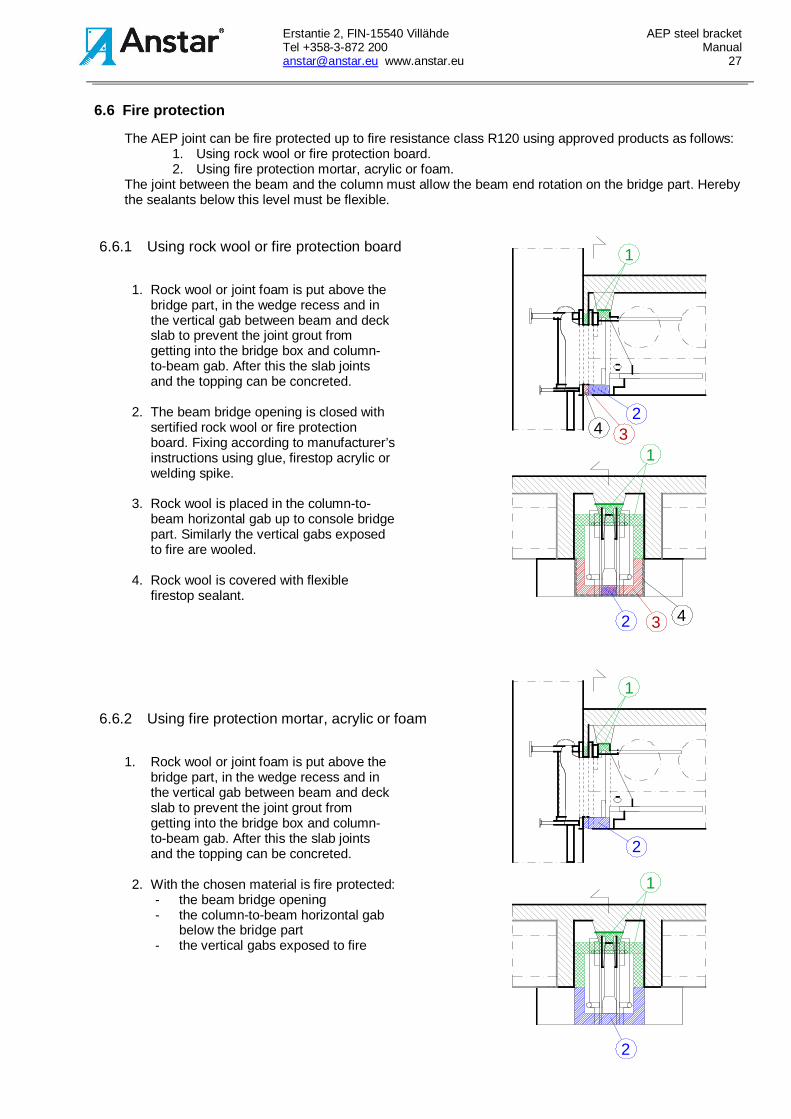
6.6 Fire protection
The AEP joint can be fire protected up to fire resistance class R120 using approved products as follows:1. Using rock wool or fire protection board.2. Using fire protection mortar, acrylic or foam.
The joint between the beam and the column must allow the beam end rotation on the bridge part. Herebythe sealants below this level must be flexible.
6.6.1 Using rock wool or fire protection board
1. Rock wool or joint foam is put above thebridge part, in the wedge recess and inthe vertical gab between beam and deckslab to prevent the joint grout fromgetting into the bridge box and column-to-beam gab. After this the slab jointsand the topping can be concreted.
2. The beam bridge opening is closed withsertified rock wool or fire protectionboard. Fixing according to manufacturer’sinstructions using glue, firestop acrylic orwelding spike.
3. Rock wool is placed in the column-to-beam horizontal gab up to console bridgepart. Similarly the vertical gabs exposedto fire are wooled.
4. Rock wool is covered with flexiblefirestop sealant.
6.6.2 Using fire protection mortar, acrylic or foam
1. Rock wool or joint foam is put above thebridge part, in the wedge recess and inthe vertical gab between beam and deckslab to prevent the joint grout fromgetting into the bridge box and column-to-beam gab. After this the slab jointsand the topping can be concreted.
2. With the chosen material is fire protected:- the beam bridge opening- the column-to-beam horizontal gab
below the bridge part- the vertical gabs exposed to fire
1
2
1
4 3
2
3 4
2
1
1
2
Erstantie 2, FIN-15540 Villähde AEP steel bracketTel +358-3-872 200 [email protected] www.anstar.eu 28
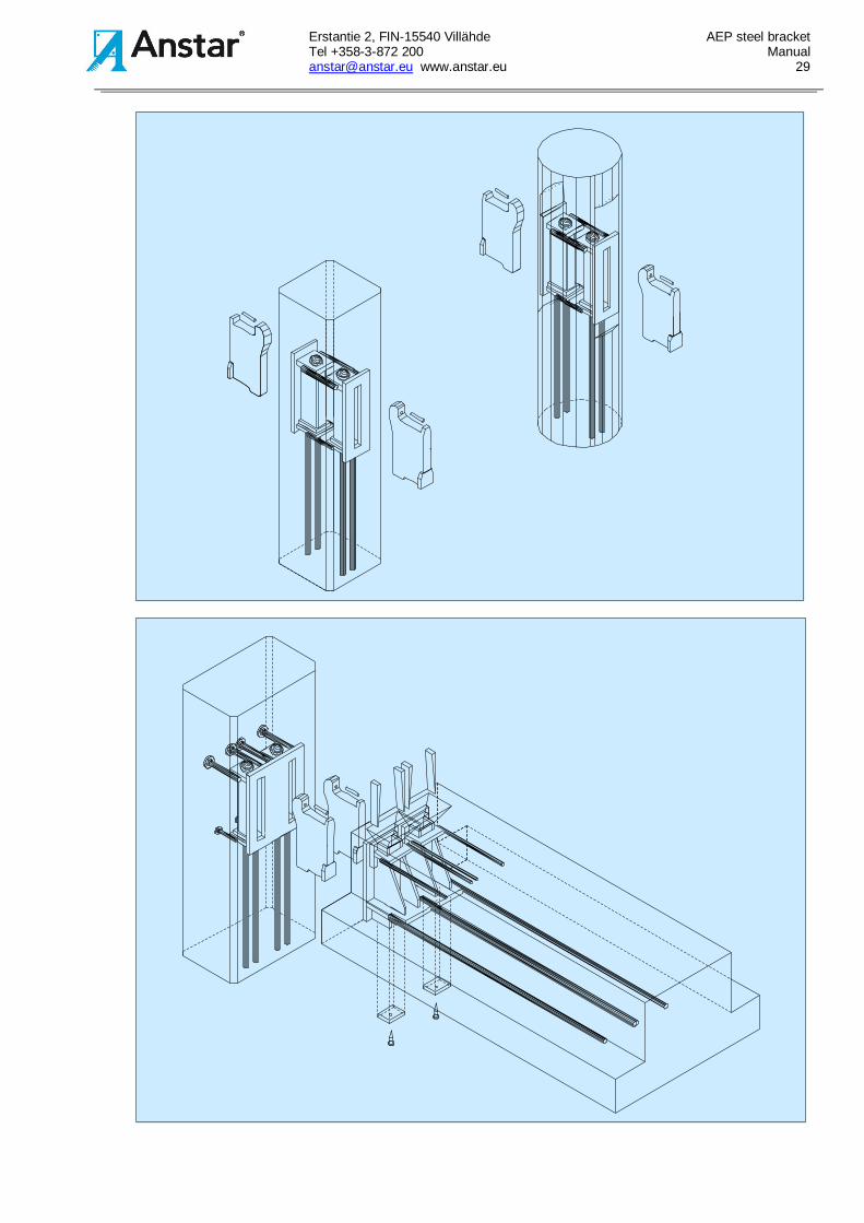
7. CONTROL PROCEDURES7.1 Instructions for precasting
1. Before concrete casting:- Check that the correct steel part (type, dimensions) is according to plan and that the parts are
undamaged.- Check that the additional reinforcement has been placed according to plan.- Beam part:
Check that the front plate is fixed tightly against the mould bottom and mould end plate and that thefront plate is perpendicular to the bottom line.Check that the wedge recess is firmly fixed and that the bridge box has been closed below thesupporting plate.
- Column part:Check that the front plate is fixed tightly against the column mould.Check that the steel part has been fixed in the correct position and the the front plate is in line withthe mould side.
2. After demoulding:- Check the concrete quality at the bracket and that the bidge boxes are clean.- Check that the steel parts are according to given tolerances (measure height level, position from
centre line and front plate inclination).
3. Bridge part assembly:- Check that the bridge part has been assembled according to plan and that it has been locked with
the tube pin.
7.2 Instructions for assembly on site
The installation is done according to the designer’s installation plan. Check list for the installationcontroller:
- The installation is done in planned order.- The column and beam supports are according to plan.- The deck slabs are assembled according to plan.- The bridge part has been wedged in the correct manner and the longitudinal beam tolerances have
been considered in the column-to-beam joints- The fire protection has been done according to given instructions.
Erstantie 2, FIN-15540 Villähde AEP steel bracketTel +358-3-872 200 [email protected] www.anstar.eu 29