Embed Size (px)
Citation preview
Establishment of Special Steel Production System at Kakogawa Works-Construction of No.3 Secondary Refining Equipment and No.6 Continuous Caster-Yasumasa YOSHIDA*1, Hideya OKADA*1, Hiroaki SAKAI*1, Hiroyuki ONODA*2, Dr. Takehiro NAKAOKA*3
*1 Steelmaking Department, Kakogawa Works, Iron & Steel Business*2 Steelmaking Development Department, Research & Development Laboratory, Iron & Steel Business*3 Mechanical Engineering Research Laboratory, Technical Development Group
Kobe Steel shut down the operation of the ironmaking and steelmaking process at Kobe Works in October 2017, and in November 2017, this upstream process was consolidated at Kakogawa Works. Prior to this, by January 2017, the Steelmaking Department of Kakogawa Works had established a special-steel production system for wire rods by installing No.3 secondary refining equipment (2LF, 4RH) and a No.6 continuous caster. A challenge in designing the new process was to produce small lots of special steel with high productivity, high yield and high quality at Kakogawa Works, which has a large heat size. In order to solve this problem, cutting edge technologies were introduced in the upstream equipment. This has enabled small-lot production and quality improvement while continuing stable production under the full production system after the consolidation of the upstream process. This paper reports the features of newly installed equipment, the concept of quality design, and the operational status.
Introduction
The Steelmaking Department of Kobe Steel's Kakogawa Works launched a new plant to consolidate the upstream process and worked to establish the manufacturing technology of special steel for wire rods and steel bars that had
been produced at Kobe Works. The department established a technology for adjusting nitrogen during molten steel processing, along with a technology for operating a 5-strand continuous bloom caster, and inaugurated a one-base system for producing crude steel at Kakogawa Works in November 2017, as planned. This paper describes the features and quality design concepts of No.3 molten steel treating equipment, including a No.4 Ruhrstahl-Heraeus degassing apparatus (4RH) and No.2 vessel furnace (2LF), as well as those of the No.6 continuous caster (6CC), and reports on their operational status after the consolidation of the upstream process.
1. Changes in steel production system
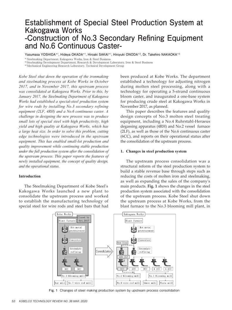
The upstream process consolidation was a structural reform of the steel production system to build a stable revenue base through steps such as reducing the costs of molten iron and steelmaking, as well as expanding the sales of the company's main products. Fig. 1 shows the changes in the steel production system associated with the consolidation of the upstream process. Kobe Steel shut down the upstream process at Kobe Works, from the blast furnace to the No.3 blooming mill plant, in
Fig. 1 Changes of steel making production system by upstream process consolidation
KOBELCO TECHNOLOGY REVIEW NO. 38 MAR. 202053
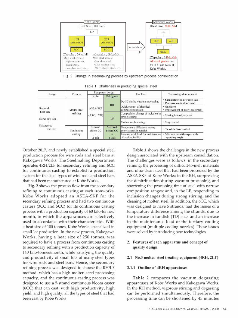
October 2017, and newly established a special steel production process for wire rods and steel bars at Kakogawa Works. The Steelmaking Department operates 4RH/2LF for secondary refining and 6CC for continuous casting to establish a production system for the steel types of wire rods and steel bars that had been manufactured at Kobe Works. Fig. 2 shows the process flow from the secondary refining to continuous casting at each ironworks. Kobe Works adopted an ASEA-SKF for the secondary refining process and had two continuous casters (3CC and 5CC) for its continuous casting process with a production capacity of 60 kilo-tonnes/month, in which the apparatuses are selectively used in accordance with their characteristics. With a heat size of 100 tonnes, Kobe Works specialized in small lot production. In the new process, Kakogawa Works, having a heat size of 250 tonnes, was required to have a process from continuous casting to secondary refining with a production capacity of 140 kilo-tonnes/month, while satisfying the quality and productivity of small lots of many steel types for wire rods and steel bars. Hence, the secondary refining process was designed to choose the RH/LF method, which has a high molten steel processing capacity, and the continuous casting process was designed to use a 5-strand continuous bloom caster (6CC) that can cast, with high productivity, high yield, and high quality, all the types of steel that had been cast by Kobe Works
Table 1 shows the challenges in the new process design associated with the upstream consolidation. The challenges were as follows: in the secondary refining, the processing of difficult-to-melt materials and ultra-clean steel that had been processed by the ASEA-SKF at Kobe Works; in the RH, suppressing the denitrification during vacuum processing, and shortening the processing time of steel with narrow composition ranges; and, in the LF, responding to inclusion changes during strong stirring, and the cleaning of molten steel. In addition, the 6CC, which was designed to have 5 strands, had the issues of a temperature difference among the strands, due to the increase in tundish (TD) size, and an increase in the maintenance load of the tertiary cooling equipment (multiple cooling nozzles). These issues were solved by introducing new technologies.
2. Features of each apparatus and concept of quality design
2.1 No.3 molten steel treating equipment (4RH, 2LF)
2.1.1 Outline of 4RH apparatuses
Table 2 compares the vacuum degassing apparatuses of Kobe Works and Kakogawa Works. In the RH method, vigorous stirring and degassing can be performed simultaneously. Therefore, the processing time can be shortened by 45 minutes
Fig. 2 Change in steelmaking process by upstream process consolidation
Table 1 Challenges in producing special steel
KOBELCO TECHNOLOGY REVIEW NO. 38 MAR. 2020 54
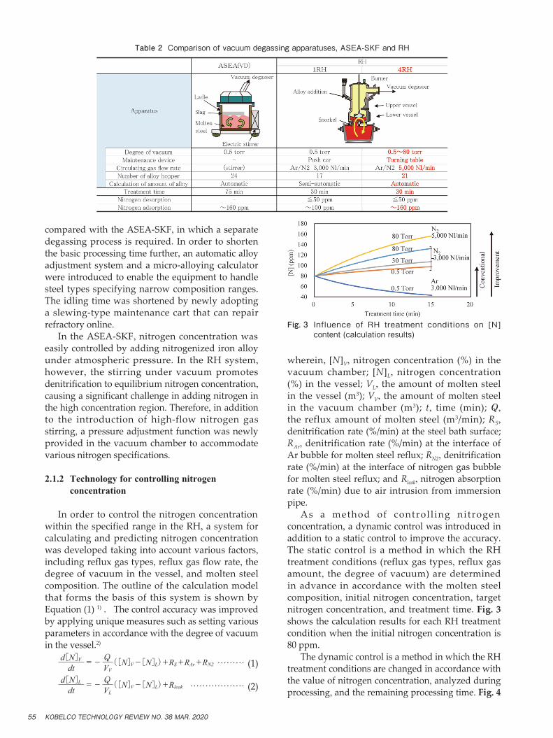
compared with the ASEA-SKF, in which a separate degassing process is required. In order to shorten the basic processing time further, an automatic alloy adjustment system and a micro-alloying calculator were introduced to enable the equipment to handle steel types specifying narrow composition ranges. The idling time was shortened by newly adopting a slewing-type maintenance cart that can repair refractory online. In the ASEA-SKF, nitrogen concentration was easily controlled by adding nitrogenized iron alloy under atmospheric pressure. In the RH system, however, the stirring under vacuum promotes denitrification to equilibrium nitrogen concentration, causing a significant challenge in adding nitrogen in the high concentration region. Therefore, in addition to the introduction of high-flow nitrogen gas stirring, a pressure adjustment function was newly provided in the vacuum chamber to accommodate various nitrogen specifications.
2.1.2 Technology for controlling nitrogen concentration
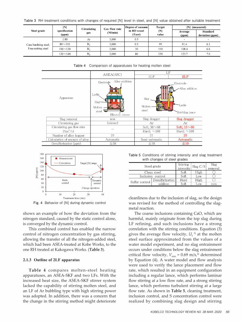
In order to control the nitrogen concentration within the specified range in the RH, a system for calculating and predicting nitrogen concentration was developed taking into account various factors, including reflux gas types, reflux gas flow rate, the degree of vacuum in the vessel, and molten steel composition. The outline of the calculation model that forms the basis of this system is shown by Equation (1) 1) . The control accuracy was improved by applying unique measures such as setting various parameters in accordance with the degree of vacuum in the vessel.2)
dtd[N]V
VV
Q=- ([N]V-[N]L)+RS+RAr+RN2 ……… (1)
dtd[N]L
VL
Q=- ([N]V-[N]L)+Rleak ……………… (2)
wherein, [N]V, nitrogen concentration (%) in the vacuum chamber; [N]L, nitrogen concentration (%) in the vessel; VL, the amount of molten steel in the vessel (m3); VV, the amount of molten steel in the vacuum chamber (m3); t, time (min); Q, the reflux amount of molten steel (m3/min); RS, denitrification rate (%/min) at the steel bath surface; RAr, denitrification rate (%/min) at the interface of Ar bubble for molten steel reflux; RN2, denitrification rate (%/min) at the interface of nitrogen gas bubble for molten steel reflux; and Rleak, nitrogen absorption rate (%/min) due to air intrusion from immersion pipe. As a method of control l ing nitrogen concentration, a dynamic control was introduced in addition to a static control to improve the accuracy. The static control is a method in which the RH treatment conditions (reflux gas types, reflux gas amount, the degree of vacuum) are determined in advance in accordance with the molten steel composition, initial nitrogen concentration, target nitrogen concentration, and treatment time. Fig. 3 shows the calculation results for each RH treatment condition when the initial nitrogen concentration is 80 ppm. The dynamic control is a method in which the RH treatment conditions are changed in accordance with the value of nitrogen concentration, analyzed during processing, and the remaining processing time. Fig. 4
Fig. 3 Influence of RH treatment conditions on [N] content (calculation results)
Table 2 Comparison of vacuum degassing apparatuses, ASEA-SKF and RH
KOBELCO TECHNOLOGY REVIEW NO. 38 MAR. 202055
shows an example of how the deviation from the nitrogen standard, caused by the static control alone, is converged by the dynamic control. This combined control has enabled the narrow control of nitrogen concentration by gas stirring, allowing the transfer of all the nitrogen-added steel, which had been ASEA-treated at Kobe Works, to the one RH treated at Kakogawa Works. (Table 3).
2.1.3 Outline of 2LF apparatus
Table 4 compares molten-steel heating apparatuses, an ASEA-SKF and two LFs. With the increased heat size, the ASEA-SKF stirrer system lacked the capability of stirring molten steel, and an LF of Ar bubbling type with high stirring power was adopted. In addition, there was a concern that the change in the stirring method might deteriorate
cleanliness due to the inclusion of slag, so the design was revised for the method of controlling the slag-metal reaction. The coarse inclusions containing CaO, which are harmful, mainly originate from the top slag during LF refining, and such inclusions have a strong correlation with the stirring conditions. Equation (3) gives the average flow velocity, U1
3) at the molten steel surface approximated from the values of a water model experiment, and no slag entrainment occurs under conditions below the slag entrainment critical flow velocity, Vmin = 0.69 m/s,4) determined by Equation (4). A water model and flow analysis were used to verify the lance placement and flow rate, which resulted in an equipment configuration including a regular lance, which performs laminar flow stirring at a low flow rate, and a strong stirring lance, which performs turbulent stirring at a large flow rate. As shown in Table 5, cleaning treatment, inclusion control, and S concentration control were realized by combining slag design and stirring
Fig. 4 Behavior of [N] during dynamic control
Table 3 RH treatment conditions with changes of required [N] level in steel, and [N] value obtained after suitable treatment
Table 4 Comparison of apparatuses for heating molten steel
Table 5 Conditions of stirring intensity and slag treatment with changes of steel grades
KOBELCO TECHNOLOGY REVIEW NO. 38 MAR. 2020 56
condition. ………………………………… (3) ………………………… (4)
U1=1.54(ε・R)0.43
Vmin=4{48g(ρm-ρs)σ}
ρs2
wherein, ρm, the density of molten steel (kg/m3); ρs, the density of slag (kg/m3); σ, molten steel/slag interfacial tension (N/m3); g, the acceleration of gravity (m/s2); ε, stirring power density (W/t); and R, vessel radius (cm). With the introduction of these new technologies, the RH equipment capable of N concentration control was combined with the LF equipment, which complements the functions of inclusion control and S concentration control, configuring the No.3 molten steel processing equipment to produce all steel types produced at Kobe Works.
2.2 No.6 continuous caster (6CC)
2.2.1 Equipment outline
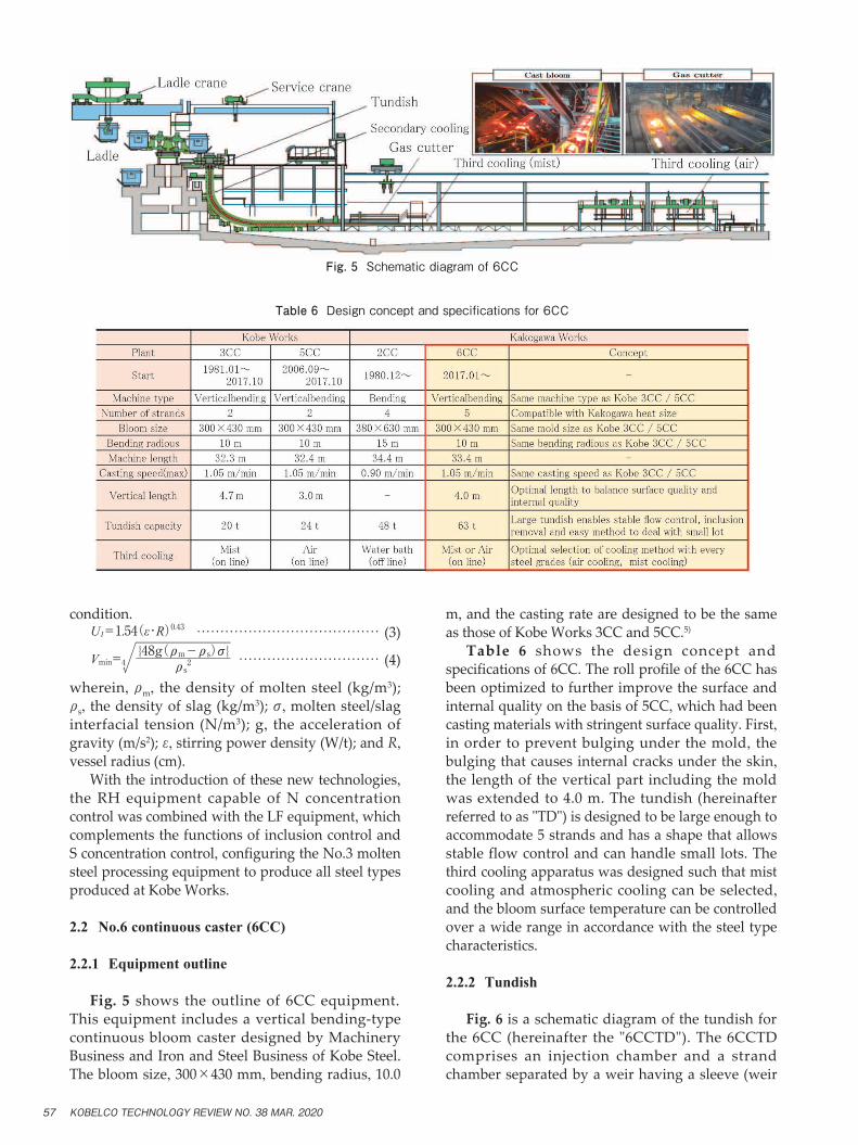
Fig. 5 shows the outline of 6CC equipment. This equipment includes a vertical bending-type continuous bloom caster designed by Machinery Business and Iron and Steel Business of Kobe Steel. The bloom size, 300×430 mm, bending radius, 10.0
m, and the casting rate are designed to be the same as those of Kobe Works 3CC and 5CC.5)
Table 6 shows the design concept and specifications of 6CC. The roll profile of the 6CC has been optimized to further improve the surface and internal quality on the basis of 5CC, which had been casting materials with stringent surface quality. First, in order to prevent bulging under the mold, the bulging that causes internal cracks under the skin, the length of the vertical part including the mold was extended to 4.0 m. The tundish (hereinafter referred to as "TD") is designed to be large enough to accommodate 5 strands and has a shape that allows stable flow control and can handle small lots. The third cooling apparatus was designed such that mist cooling and atmospheric cooling can be selected, and the bloom surface temperature can be controlled over a wide range in accordance with the steel type characteristics.
2.2.2 Tundish
Fig. 6 is a schematic diagram of the tundish for the 6CC (hereinafter the "6CCTD"). The 6CCTD comprises an injection chamber and a strand chamber separated by a weir having a sleeve (weir
Table 6 Design concept and specifications for 6CC
Fig. 5 Schematic diagram of 6CC
KOBELCO TECHNOLOGY REVIEW NO. 38 MAR. 202057
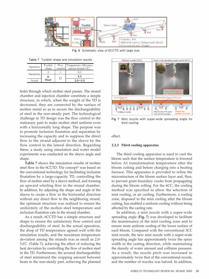
hole) through which molten steel passes. The strand chamber and injection chamber constitute a simple structure, in which, when the weight of the TD is decreased, they are connected by the surface of molten metal so as to secure the dischargeability of steel in the non-steady part. The technological challenge in TD design was the flow control in the stationary part to make molten steel uniform even with a horizontally long shape. The purpose was to promote inclusion floatation and separation by increasing the capacity and to suppress the direct flow to the strand adjacent to the sleeve by the flow control in the lateral direction. Regarding these, a study using simulation and water model experiments was conducted on the sleeve angle and shape. Table 7 shows the simulation results of molten steel flow in the 6CCTD. The concept6) was based on the conventional technology for facilitating inclusion floatation by a large-capacity TD, controlling the flow of molten steel by a sleeve method, and forming an upward whirling flow in the strand chamber.In addition, by adjusting the shape and angle of the sleeve to create a flow in the horizontal direction without any direct flow to the neighboring strand, the optimum structure was realized to ensure the uniformity of the molten steel temperature and inclusion floatation rate in the strand chamber. As a result, 6CCTD has a simple structure and shape to ensure the satisfactory flow control and dischargeability of steel. In the actual operation, the drop of TD temperature agreed well with the simulation results, and the maximum temperature deviation among the strands was as small as 2.0-5.0℃ (Table 7), achieving the effect of reducing the heat deviation by controlling the flow of molten steel in the TD. Furthermore, the secured dischargeability of steel minimized the cropping amount between heats in the non-steady part, achieving the planned
effect.
2.2.3 Third cooling apparatus
The third cooling apparatus is used to cool the bloom such that the surface temperature is lowered below A1 transformation temperature after the bloom cutting and before charging into a heating furnace. This apparatus is provided to refine the microstructure of the bloom surface layer and, thus, to prevent grain boundary cracks from propagating during the bloom rolling. For the 6CC, the cooling method was specified to allow the selection of mist cooling, or air cooling. Furthermore, a cooling zone, disposed in the mist cooling after the bloom cutting, has enabled a uniform cooling without being affected by the casting rate. In addition, a mist nozzle with a super-wide spreading angle (Fig. 7) was developed to facilitate the maintenance of the mist cooling zone and to ensure more uniform cooling of the lower surface of each bloom. Compared with the conventional 3CC mist nozzle, the new mist nozzle with a super-wide spreading angle has approximately twice the spray width in the casting direction, while maintaining the density of water amount and collision pressure. As a result, the nozzle pitch was increased to approximately twice that of the conventional nozzle, and the number of nozzles was halved. In addition,
Table 7 Tundish shape and simulation results
Fig. 7 Mist nozzle with super-wide spreading angle for third cooling
Fig. 6 Schematic view of 6CCTD with large size
KOBELCO TECHNOLOGY REVIEW NO. 38 MAR. 2020 58
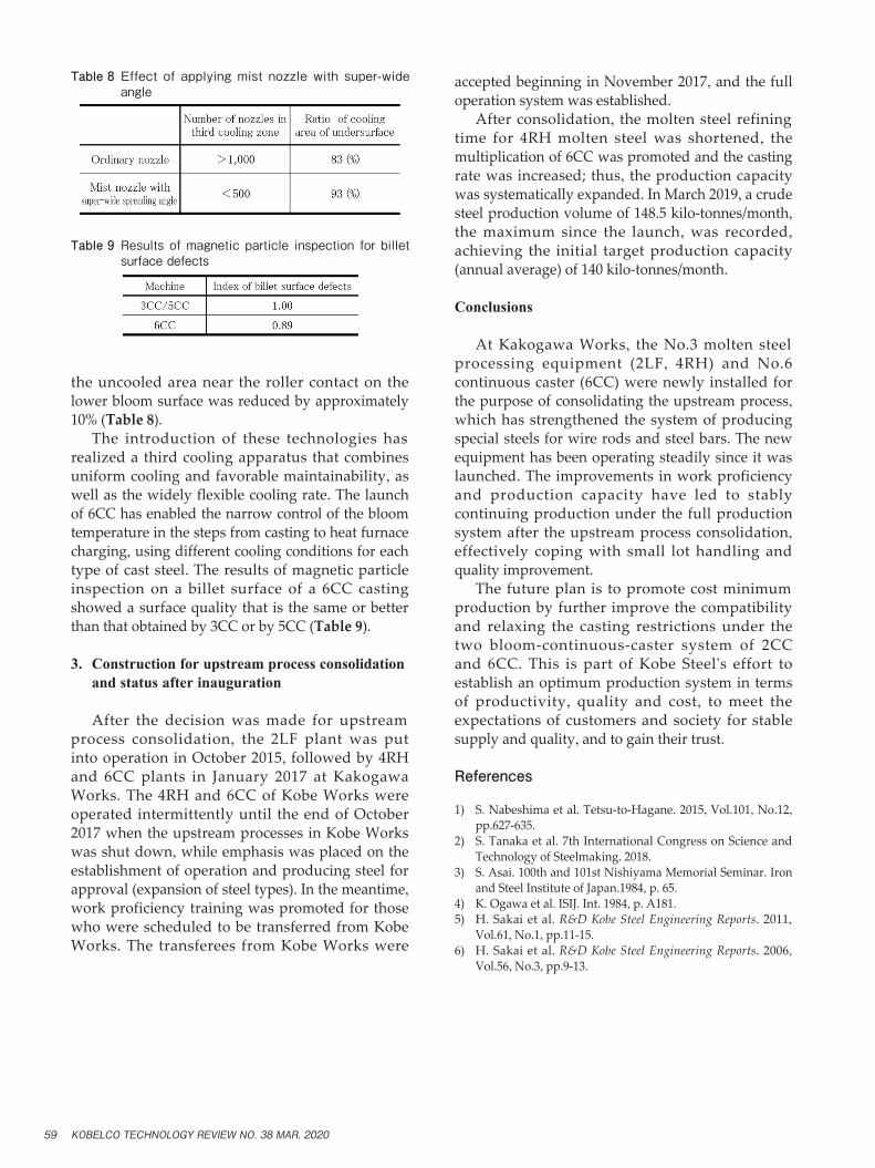
the uncooled area near the roller contact on the lower bloom surface was reduced by approximately 10% (Table 8). The introduction of these technologies has realized a third cooling apparatus that combines uniform cooling and favorable maintainability, as well as the widely flexible cooling rate. The launch of 6CC has enabled the narrow control of the bloom temperature in the steps from casting to heat furnace charging, using different cooling conditions for each type of cast steel. The results of magnetic particle inspection on a billet surface of a 6CC casting showed a surface quality that is the same or better than that obtained by 3CC or by 5CC (Table 9).
3. Construction for upstream process consolidation and status after inauguration
After the decision was made for upstream process consolidation, the 2LF plant was put into operation in October 2015, followed by 4RH and 6CC plants in January 2017 at Kakogawa Works. The 4RH and 6CC of Kobe Works were operated intermittently until the end of October 2017 when the upstream processes in Kobe Works was shut down, while emphasis was placed on the establishment of operation and producing steel for approval (expansion of steel types). In the meantime, work proficiency training was promoted for those who were scheduled to be transferred from Kobe Works. The transferees from Kobe Works were
accepted beginning in November 2017, and the full operation system was established. After consolidation, the molten steel refining time for 4RH molten steel was shortened, the multiplication of 6CC was promoted and the casting rate was increased; thus, the production capacity was systematically expanded. In March 2019, a crude steel production volume of 148.5 kilo-tonnes/month, the maximum since the launch, was recorded, achieving the initial target production capacity (annual average) of 140 kilo-tonnes/month.
Conclusions
At Kakogawa Works, the No.3 molten steel processing equipment (2LF, 4RH) and No.6 continuous caster (6CC) were newly installed for the purpose of consolidating the upstream process, which has strengthened the system of producing special steels for wire rods and steel bars. The new equipment has been operating steadily since it was launched. The improvements in work proficiency and production capacity have led to stably continuing production under the full production system after the upstream process consolidation, effectively coping with small lot handling and quality improvement. The future plan is to promote cost minimum production by further improve the compatibility and relaxing the casting restrictions under the two bloom-continuous-caster system of 2CC and 6CC. This is part of Kobe Steel's effort to establish an optimum production system in terms of productivity, quality and cost, to meet the expectations of customers and society for stable supply and quality, and to gain their trust.
References
1) S. Nabeshima et al. Tetsu-to-Hagane. 2015, Vol.101, No.12, pp.627-635.
2) S. Tanaka et al. 7th International Congress on Science and Technology of Steelmaking. 2018.
3) S. Asai. 100th and 101st Nishiyama Memorial Seminar. Iron and Steel Institute of Japan.1984, p. 65.
4) K. Ogawa et al. ISIJ. Int. 1984, p. A181.5) H. Sakai et al. R&D Kobe Steel Engineering Reports. 2011,
Vol.61, No.1, pp.11-15.6) H. Sakai et al. R&D Kobe Steel Engineering Reports. 2006,
Vol.56, No.3, pp.9-13.
Table 8 Effect of applying mist nozzle with super-wide angle
Table 9 Results of magnetic particle inspection for billet surface defects
KOBELCO TECHNOLOGY REVIEW NO. 38 MAR. 202059


![DAEHAN - suspipe.co.krsuspipe.co.kr/WebData/Web_2.pdf · daehan special steel daehan special steel [08 09] ® 5fotjpo mfwfmmfs z @ Ë Ì j ; 3 b v ² ø ; x d d 8 j à k b ñ 5 ý](https://img.pdfslide.tips/doc/110x75/5e084bca91f50949203c2b87/daehan-daehan-special-steel-daehan-special-steel-08-09-5fotjpo-mfwfmmfs-z.jpg)