Embed Size (px)
Citation preview
Kemistintie 3, Espoo P.O.Box 1001, FI-02044 VTT, FINLAND www.vttexpertservices.fi
Member of
www.eota.eu
Translations of this European Technical Assessment in other languages shall fully correspond to the original issued document and
should be identified as such.
Communication of this European Technical Assessment, including transmission by electronic means, shall be in full excepted the
confidential Annex(es) referred to above. However, partial reproduction may be made, with the written consent of the issuing
Technical Assessment Body. Any partial reproduction has to be identified as such.
European Technical Assessment
ETA‐10/0472 of 09/05/2017
GENERAL PART
TECHNICAL ASSESSMENT BODY ISSUING THE ETA AND
DESIGNATED ACCORDING TO ARTICLE 29 OF THE
REGULATION (EU) NO 305/2011
VTT EXPERT SERVICES LTD
TRADE NAME OF THE CONSTRUCTION PRODUCT SMART THROUGH BOLT ANCHORS S‐KA, S‐KAK,
S‐KAH, AND S‐KAH HCR
PRODUCT FAMILY TO WHICH THE CONSTRUCTION
PRODUCT BELONGS
TORQUE CONTROLLED EXPANSION ANCHORS OF
SIZES M8, M10, M12 AND M16 FOR USE IN
CONCRETE
MANUFACTURER PGB‐POLSKA SP. Z O.O.
UL. FRYDERYKA WILHELMA REDENA 3
41‐807 ZABRZE
POLAND
MANUFACTURING PLANT PGB‐POLSKA SMART PLANT II
THIS EUROPEAN TECHNICAL ASSESSMENT CONTAINS 14 PAGES INCLUDING 11 ANNEXES
WHICH FORM AN INTEGRAL PART OF THIS
ASSESSMENT
THIS EUROPEAN TECHNICAL ASSESSMENT IS ISSUED IN
ACCORDANCE WITH REGULATION
(EU) NO 305/2011, ON THE BASIS OF
GUIDELINES FOR EUROPEAN TECHNICAL APPROVAL
ETAG 001 METAL ANCHORS FOR USE IN CONCRETE
PART 1 AND PART 2, APRIL 2013, USED AS EUROPEAN
ASSESSMENT DOCUMENT (EAD).
THIS VERSION REPLACES EUROPEAN TECHNICAL ASSESSMENT
ETA‐10/0472 from 08/09/2016
ETA‐10/0472 of 9/5/2017 ‐ page 2 of 14
SPECIFIC PART
1. Technical description of the product
The SMART S‐KA is an anchor made of galvanized steel (designated as S‐KA). The SMART S‐KAK is an
anchor made of hot dip galvanized steel (designated as S‐KAK). The SMART S‐KAH is an anchor made of
stainless steel (designated as S‐KAH). The SMART S‐KAH HCR is an anchor made of high corrosion resistant
stainless steel (designated as S‐KAH HCR). The anchors are made in sizes M8, M10, M12 and M16. Anchors
are placed into a drilled hole and anchored by torque‐controlled expansion.
The illustration and description of the product are given in Annexes A.
2. Specification of the intended use in accordance with the applicable European Assessment
Document, EAD
The performances given in Section 3 are only valid if the anchor is used in compliance with the
specifications and conditions given in Annexes B.
The provisions made in this European technical assessment are based on an assumed working life of the
anchor of at least 50 years. The indications given on the working life cannot be interpreted as a guarantee
given by the producer, but are to be regarded only as a means for choosing the right products in relation
to the expected economically reasonable working life of the works.
3. Performance of the product and references to the methods used for its assessment
3.1 Mechanical resistance and stability (BWR 1)
Essential characteristic Performance
Characteristic tension resistance for static and quasi‐static action
acc. ETAG 001, Annex C or CEN/TS 1992‐4:2009
See Annex C1
Characteristic shear resistance for static and quasi‐static action
acc. ETAG 001, Annex C or CEN/TS 1992‐4:2009
See Annex C2
Characteristic resistance for Seismic Performance Category C1 See Annex C6
Displacements under static and quasi‐static action See Annex C5
3.2 Safety in case of fire (BWR 2)
Essential characteristic Performance
Reaction to fire Anchorages satisfy
requirements for Class A1
Characteristic tension resistance under fire exposure See Annex C3
Characteristic shear resistance under fire exposure See Annex C4
3.3 Hygiene, health and the environment (BWR 3) Regarding dangerous substances contained in this European technical approval, there may be
requirements applicable to the products falling within its scope (e.g. transposed European legislation
and national laws, regulations and administrative provisions). In order to meet the provisions of the
Construction Products Directive, these requirements need also to be complied with, when and
where they apply.
ETA‐10/0472 of 9/5/2017 ‐ page 3 of 14
3.4 Safety in use (BWR 4) For basic requirement Safety in use the same criteria are valid for Basic Requirement Mechanical
resistance and stability (BWR1).
3.5 Protection against noise (BWR5): Not relevant.
3.6 Energy economy and heat retention (BWR6): Not relevant.
3.7 Sustainable use of natural resources (BWR7) The sustainable use of natural resources was not investigated.
3.8 General aspects relating to fitness for use Durability and Serviceability are only ensured if the specifications of intended use according to Annex
B1 are kept.
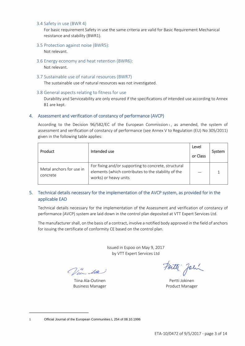
4. Assessment and verification of constancy of performance (AVCP)
According to the Decision 96/582/EC of the European Commission 1 , as amended, the system of
assessment and verification of constancy of performance (see Annex V to Regulation (EU) No 305/2011)
given in the following table applies:
Product Intended use Level
or Class System
Metal anchors for use in
concrete
For fixing and/or supporting to concrete, structural
elements (which contributes to the stability of the
works) or heavy units ― 1
5. Technical details necessary for the implementation of the AVCP system, as provided for in the
applicable EAD
Technical details necessary for the implementation of the Assessment and verification of constancy of
performance (AVCP) system are laid down in the control plan deposited at VTT Expert Services Ltd.
The manufacturer shall, on the basis of a contract, involve a notified body approved in the field of anchors
for issuing the certificate of conformity CE based on the control plan.
Issued in Espoo on May 9, 2017
by VTT Expert Services Ltd
Tiina Ala‐Outinen Pertti Jokinen Business Manager Product Manager
1 Official Journal of the European Communities L 254 of 08.10.1996
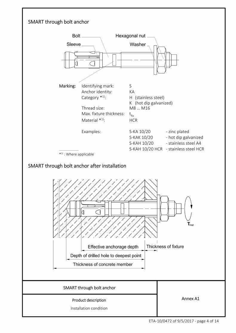
SMART through bolt anchor
Product description
Installation condition
Annex A1
ETA‐10/0472 of 9/5/2017 ‐ page 4 of 14
SMART through bolt anchor
Marking: Identifying mark: S Anchor identity: KA Category *1): H (stainless steel) K (hot dip galvanized) Thread size: M8 … M16 Max. fixture thickness:
f t
fix
Material *1): HCR Examples: S‐KA 10/20 ‐ zinc plated S‐KAK 10/20 ‐ hot dip galvanized S‐KAH 10/20 ‐ stainless steel A4 S‐KAH 10/20 HCR ‐ stainless steel HCR *1) : Where applicable
SMART through bolt anchor after installation
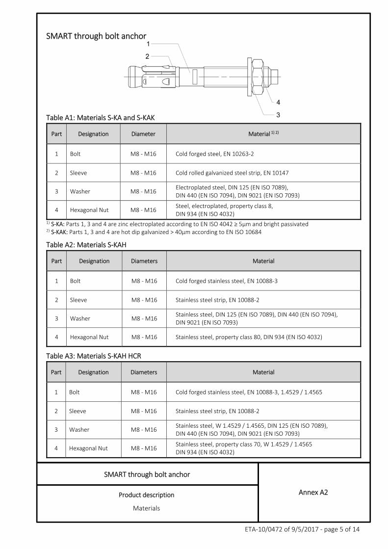
SMART through bolt anchor
Product description
Materials
Annex A2
ETA‐10/0472 of 9/5/2017 ‐ page 5 of 14
SMART through bolt anchor
Table A1: Materials S‐KA and S‐KAK
Part Designation Diameter Material 1) 2)
1 Bolt M8 ‐ M16 Cold forged steel, EN 10263‐2
2 Sleeve M8 ‐ M16 Cold rolled galvanized steel strip, EN 10147
3 Washer M8 ‐ M16 Electroplated steel, DIN 125 (EN ISO 7089), DIN 440 (EN ISO 7094), DIN 9021 (EN ISO 7093)
4 Hexagonal Nut M8 ‐ M16 Steel, electroplated, property class 8, DIN 934 (EN ISO 4032)
1) S‐KA: Parts 1, 3 and 4 are zinc electroplated according to EN ISO 4042 ≥ 5μm and bright passivated 2) S‐KAK: Parts 1, 3 and 4 are hot dip galvanized > 40μm according to EN ISO 10684
Table A2: Materials S‐KAH
Part Designation Diameters Material
1 Bolt M8 ‐ M16 Cold forged stainless steel, EN 10088‐3
2 Sleeve M8 ‐ M16 Stainless steel strip, EN 10088‐2
3 Washer M8 ‐ M16 Stainless steel, DIN 125 (EN ISO 7089), DIN 440 (EN ISO 7094), DIN 9021 (EN ISO 7093)
4 Hexagonal Nut M8 ‐ M16 Stainless steel, property class 80, DIN 934 (EN ISO 4032)
Table A3: Materials S‐KAH HCR
Part Designation Diameters Material
1 Bolt M8 ‐ M16 Cold forged stainless steel, EN 10088‐3, 1.4529 / 1.4565
2 Sleeve M8 ‐ M16 Stainless steel strip, EN 10088‐2
3 Washer M8 ‐ M16 Stainless steel, W 1.4529 / 1.4565, DIN 125 (EN ISO 7089), DIN 440 (EN ISO 7094), DIN 9021 (EN ISO 7093)
4 Hexagonal Nut M8 ‐ M16 Stainless steel, property class 70, W 1.4529 / 1.4565 DIN 934 (EN ISO 4032)
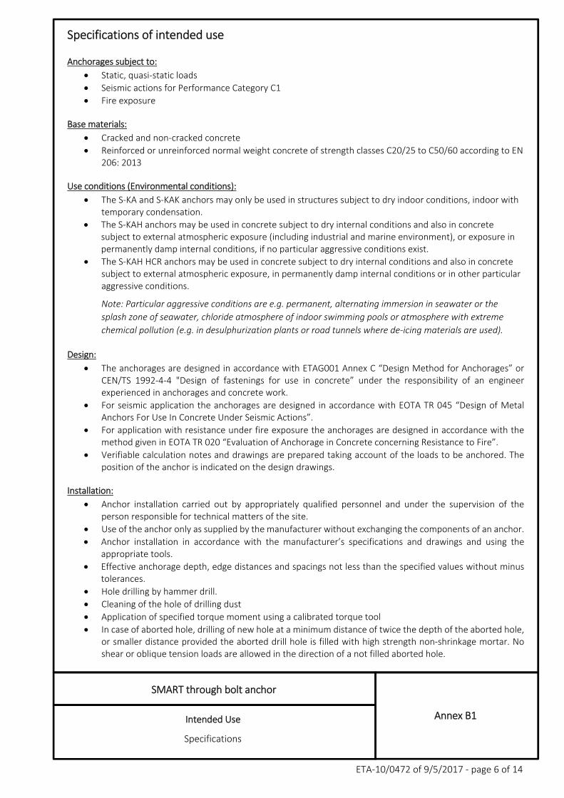
SMART through bolt anchor
Intended Use
Specifications
Annex B1
ETA‐10/0472 of 9/5/2017 ‐ page 6 of 14
Specifications of intended use
Anchorages subject to:
Static, quasi‐static loads
Seismic actions for Performance Category C1
Fire exposure
Base materials:
Cracked and non‐cracked concrete
Reinforced or unreinforced normal weight concrete of strength classes C20/25 to C50/60 according to EN 206: 2013
Use conditions (Environmental conditions):
The S‐KA and S‐KAK anchors may only be used in structures subject to dry indoor conditions, indoor with temporary condensation.
The S‐KAH anchors may be used in concrete subject to dry internal conditions and also in concrete subject to external atmospheric exposure (including industrial and marine environment), or exposure in permanently damp internal conditions, if no particular aggressive conditions exist.
The S‐KAH HCR anchors may be used in concrete subject to dry internal conditions and also in concrete subject to external atmospheric exposure, in permanently damp internal conditions or in other particular aggressive conditions.
Note: Particular aggressive conditions are e.g. permanent, alternating immersion in seawater or the
splash zone of seawater, chloride atmosphere of indoor swimming pools or atmosphere with extreme
chemical pollution (e.g. in desulphurization plants or road tunnels where de‐icing materials are used).
Design:
The anchorages are designed in accordance with ETAG001 Annex C “Design Method for Anchorages” or CEN/TS 1992‐4‐4 "Design of fastenings for use in concrete” under the responsibility of an engineer experienced in anchorages and concrete work.
For seismic application the anchorages are designed in accordance with EOTA TR 045 “Design of Metal Anchors For Use In Concrete Under Seismic Actions”.
For application with resistance under fire exposure the anchorages are designed in accordance with the method given in EOTA TR 020 “Evaluation of Anchorage in Concrete concerning Resistance to Fire”.
Verifiable calculation notes and drawings are prepared taking account of the loads to be anchored. The position of the anchor is indicated on the design drawings.
Installation:
Anchor installation carried out by appropriately qualified personnel and under the supervision of the person responsible for technical matters of the site.
Use of the anchor only as supplied by the manufacturer without exchanging the components of an anchor.
Anchor installation in accordance with the manufacturer’s specifications and drawings and using the appropriate tools.
Effective anchorage depth, edge distances and spacings not less than the specified values without minus tolerances.
Hole drilling by hammer drill.
Cleaning of the hole of drilling dust
Application of specified torque moment using a calibrated torque tool
In case of aborted hole, drilling of new hole at a minimum distance of twice the depth of the aborted hole, or smaller distance provided the aborted drill hole is filled with high strength non‐shrinkage mortar. No shear or oblique tension loads are allowed in the direction of a not filled aborted hole.
SMART through bolt anchor
Intended Use
Anchor dimensions
Annex B2
ETA‐10/0472 of 9/5/2017 ‐ page 7 of 14
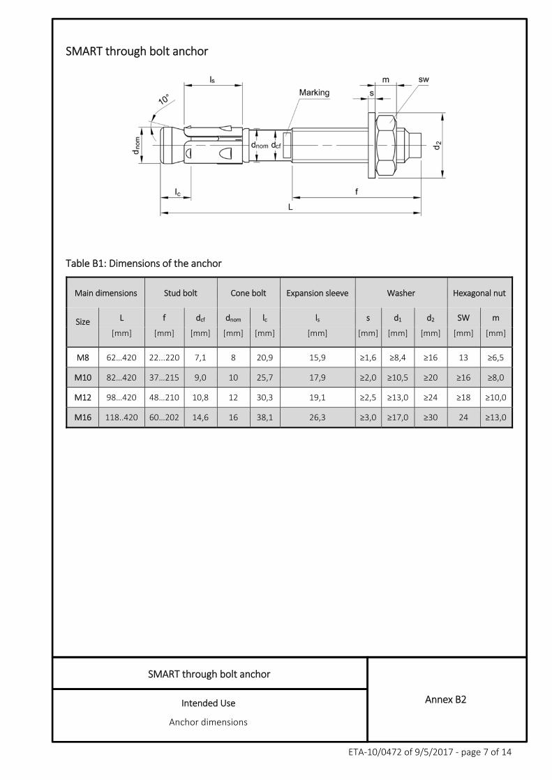
SMART through bolt anchor
Table B1: Dimensions of the anchor
Main dimensions Stud bolt Cone bolt Expansion sleeve Washer Hexagonal nut
Size
L f dcf dnom lc ls s d1 d2 SW m
[mm] [mm] [mm] [mm] [mm] [mm] [mm] [mm] [mm] [mm] [mm]
M8 62…420 22...220 7,1 8 20,9 15,9 ≥1,6 ≥8,4 ≥16 13 ≥6,5
M10 82…420 37…215 9,0 10 25,7 17,9 ≥2,0 ≥10,5 ≥20 ≥16 ≥8,0
M12 98…420 48…210 10,8 12 30,3 19,1 ≥2,5 ≥13,0 ≥24 ≥18 ≥10,0
M16 118..420 60…202 14,6 16 38,1 26,3 ≥3,0 ≥17,0 ≥30 24 ≥13,0
SMART through bolt anchor
Intended Use
Installation data
Annex B3
ETA‐10/0472 of 9/5/2017 ‐ page 8 of 14
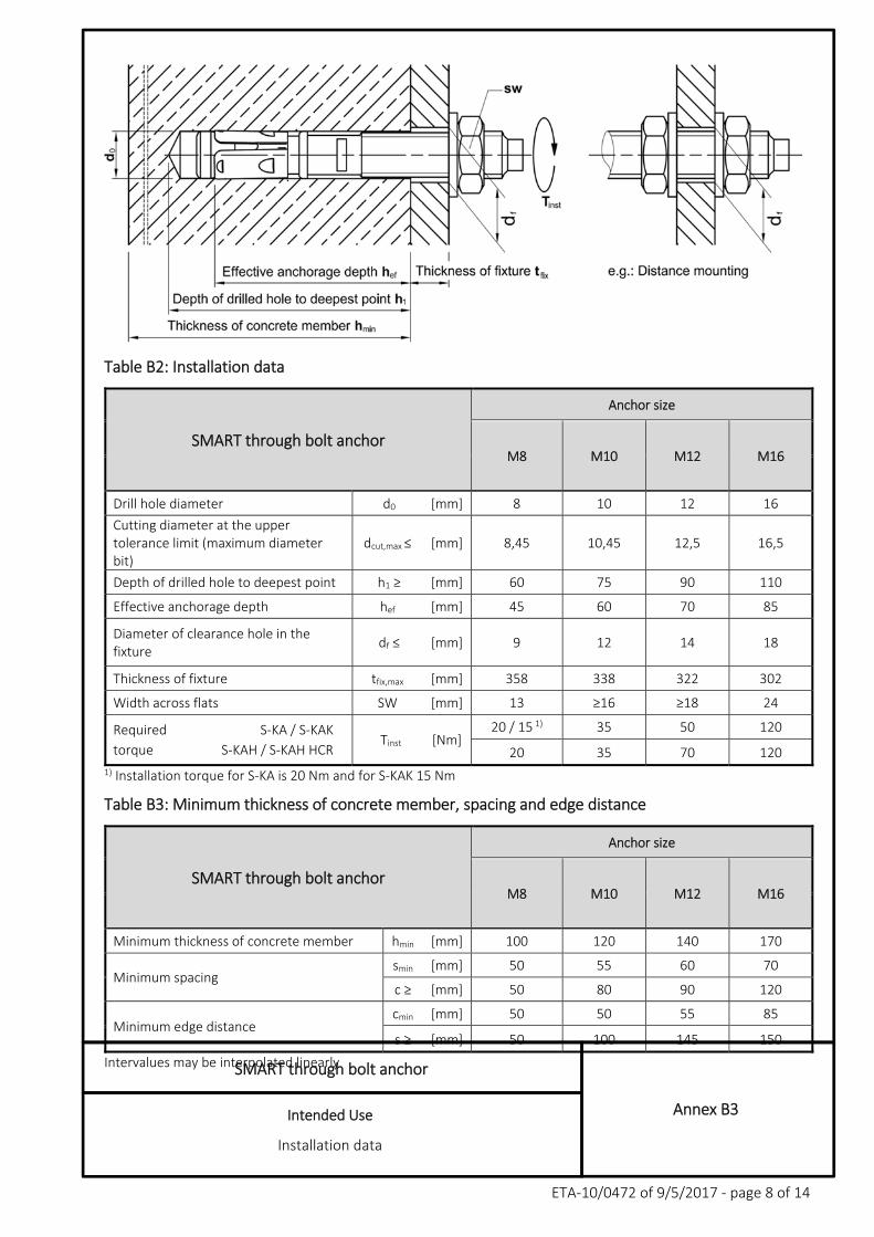
Table B2: Installation data
SMART through bolt anchor
Anchor size
M8 M10 M12 M16
Drill hole diameter d0 [mm] 8 10 12 16
Cutting diameter at the upper tolerance limit (maximum diameter bit)
dcut,max ≤ [mm] 8,45 10,45 12,5 16,5
Depth of drilled hole to deepest point h1 ≥ [mm] 60 75 90 110
Effective anchorage depth hef [mm] 45 60 70 85
Diameter of clearance hole in the fixture
df ≤ [mm] 9 12 14 18
Thickness of fixture tfix,max [mm] 358 338 322 302
Width across flats SW [mm] 13 ≥16 ≥18 24
Required S‐KA / S‐KAK Tinst [Nm]
20 / 15 1) 35 50 120
torque S‐KAH / S‐KAH HCR 20 35 70 120 1) Installation torque for S‐KA is 20 Nm and for S‐KAK 15 Nm
Table B3: Minimum thickness of concrete member, spacing and edge distance
SMART through bolt anchor
Anchor size
M8 M10 M12 M16
Minimum thickness of concrete member hmin [mm] 100 120 140 170
Minimum spacing smin [mm] 50 55 60 70
c ≥ [mm] 50 80 90 120
Minimum edge distance cmin [mm] 50 50 55 85
s ≥ [mm] 50 100 145 150
Intervalues may be interpolated linearly
SMART through bolt anchor
Performance
Characteristic resistance under tension loads
Annex C1
ETA‐10/0472 of 9/5/2017 ‐ page 9 of 14
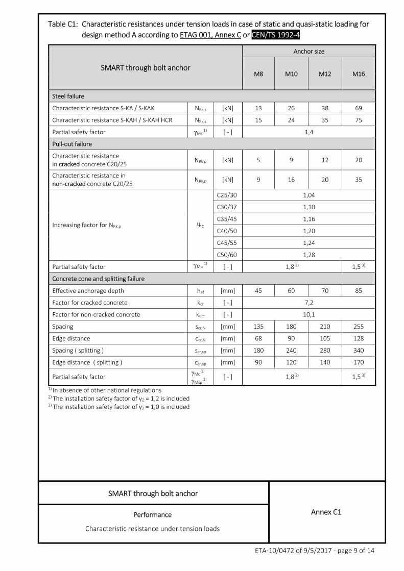
Table C1: Characteristic resistances under tension loads in case of static and quasi‐static loading for
design method A according to ETAG 001, Annex C or CEN/TS 1992‐4
SMART through bolt anchor
Anchor size
M8 M10 M12 M16
Steel failure
Characteristic resistance S‐KA / S‐KAK NRk,s [kN] 13 26 38 69
Characteristic resistance S‐KAH / S‐KAH HCR NRk,s [kN] 15 24 35 75
Partial safety factor γMs 1) [ ‐ ] 1,4
Pull‐out failure
Characteristic resistance in cracked concrete C20/25
NRk,p [kN] 5 9 12 20
Characteristic resistance in non‐cracked concrete C20/25
NRk,p [kN] 9 16 20 35
Increasing factor for NRk,p ΨC
C25/30 1,04
C30/37 1,10
C35/45 1,16
C40/50 1,20
C45/55 1,24
C50/60 1,28
Partial safety factor γMp1)
[ ‐ ] 1,8 2) 1,5 3)
Concrete cone and splitting failure
Effective anchorage depth hef [mm] 45 60 70 85
Factor for cracked concrete kcr [ ‐ ] 7,2
Factor for non‐cracked concrete kucr [ ‐ ] 10,1
Spacing scr,N [mm] 135 180 210 255
Edge distance ccr,N [mm] 68 90 105 128
Spacing ( splitting ) scr,sp [mm] 180 240 280 340
Edge distance ( splitting ) ccr,sp [mm] 90 120 140 170
Partial safety factor γMc
1)
γMsp 1)
[ ‐ ] 1,8 2) 1,5 3)
1) In absence of other national regulations 2) The installation safety factor of γ2 = 1,2 is included 3) The installation safety factor of γ2 = 1,0 is included
SMART through bolt anchor
Performance
Characteristic resistance under shear loads
Annex C2
ETA‐10/0472 of 9/5/2017 ‐ page 10 of 14
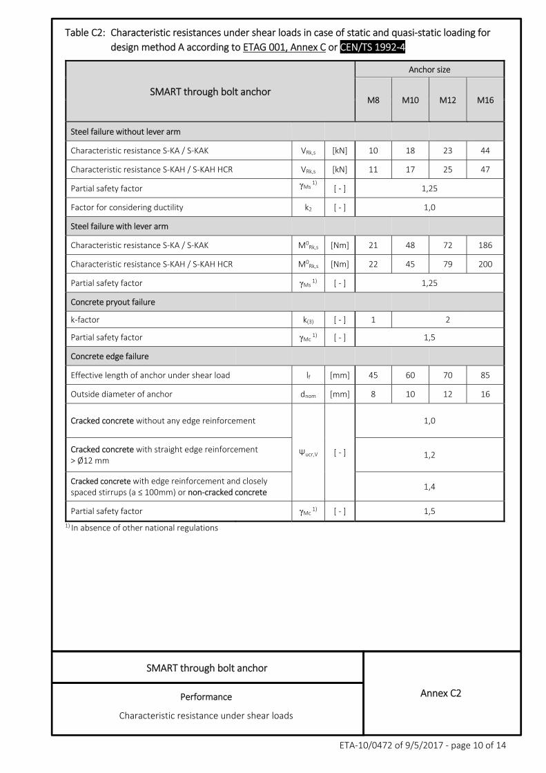
Table C2: Characteristic resistances under shear loads in case of static and quasi‐static loading for
design method A according to ETAG 001, Annex C or CEN/TS 1992‐4
SMART through bolt anchor
Anchor size
M8 M10 M12 M16
Steel failure without lever arm
Characteristic resistance S‐KA / S‐KAK VRk,s [kN] 10 18 23 44
Characteristic resistance S‐KAH / S‐KAH HCR VRk,s [kN] 11 17 25 47
Partial safety factor γMs1)
[ ‐ ] 1,25
Factor for considering ductility k2 [ ‐ ] 1,0
Steel failure with lever arm
Characteristic resistance S‐KA / S‐KAK M0Rk,s [Nm] 21 48 72 186
Characteristic resistance S‐KAH / S‐KAH HCR M0Rk,s [Nm] 22 45 79 200
Partial safety factor γMs 1) [ ‐ ] 1,25
Concrete pryout failure
k‐factor k(3) [ ‐ ] 1 2
Partial safety factor γMc 1) [ ‐ ] 1,5
Concrete edge failure
Effective length of anchor under shear load lf [mm] 45 60 70 85
Outside diameter of anchor dnom [mm] 8 10 12 16
Cracked concrete without any edge reinforcement
Ψucr,V [ ‐ ]
1,0
Cracked concrete with straight edge reinforcement > Ø12 mm
1,2
Cracked concrete with edge reinforcement and closely spaced stirrups (a ≤ 100mm) or non‐cracked concrete
1,4
Partial safety factor γMc 1) [ ‐ ] 1,5
1) In absence of other national regulations
SMART through bolt anchor
Performance
Characteristic tension resistance under fire exposure
Annex C3
ETA‐10/0472 of 9/5/2017 ‐ page 11 of 14
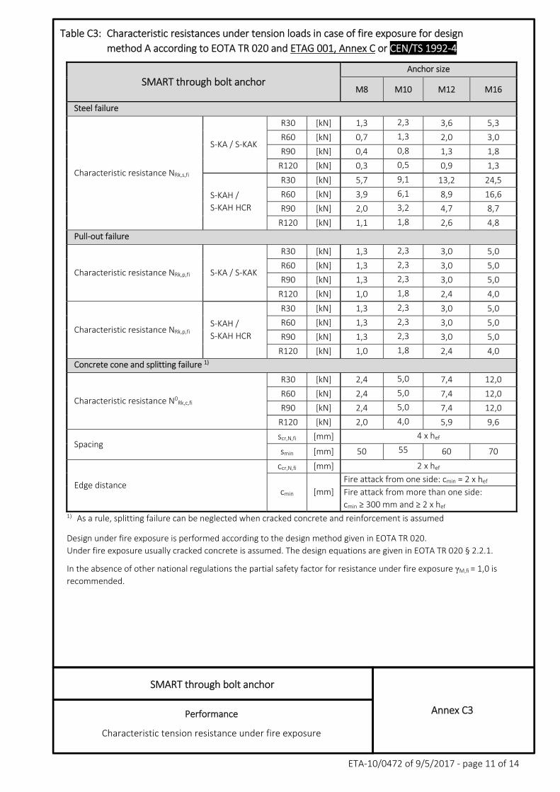
Table C3: Characteristic resistances under tension loads in case of fire exposure for design
method A according to EOTA TR 020 and ETAG 001, Annex C or CEN/TS 1992‐4
SMART through bolt anchor Anchor size
M8 M10 M12 M16
Steel failure
Characteristic resistance NRk,s,fi
S‐KA / S‐KAK
R30 [kN] 1,3 2,3 3,6 5,3
R60 [kN] 0,7 1,3 2,0 3,0
R90 [kN] 0,4 0,8 1,3 1,8
R120 [kN] 0,3 0,5 0,9 1,3
S‐KAH /
S‐KAH HCR
R30 [kN] 5,7 9,1 13,2 24,5
R60 [kN] 3,9 6,1 8,9 16,6
R90 [kN] 2,0 3,2 4,7 8,7
R120 [kN] 1,1 1,8 2,6 4,8
Pull‐out failure
Characteristic resistance NRk,p,fi S‐KA / S‐KAK
R30 [kN] 1,3 2,3 3,0 5,0
R60 [kN] 1,3 2,3 3,0 5,0
R90 [kN] 1,3 2,3 3,0 5,0
R120 [kN] 1,0 1,8 2,4 4,0
Characteristic resistance NRk,p,fi S‐KAH /
S‐KAH HCR
R30 [kN] 1,3 2,3 3,0 5,0
R60 [kN] 1,3 2,3 3,0 5,0
R90 [kN] 1,3 2,3 3,0 5,0
R120 [kN] 1,0 1,8 2,4 4,0
Concrete cone and splitting failure 1)
Characteristic resistance N0Rk,c,fi
R30 [kN] 2,4 5,0 7,4 12,0
R60 [kN] 2,4 5,0 7,4 12,0
R90 [kN] 2,4 5,0 7,4 12,0
R120 [kN] 2,0 4,0 5,9 9,6
Spacing scr,N,fi [mm] 4 x hef
smin [mm] 50 55 60 70
Edge distance
ccr,N,fi [mm] 2 x hef
cmin [mm]
Fire attack from one side: cmin = 2 x hef
Fire attack from more than one side:
cmin ≥ 300 mm and ≥ 2 x hef 1) As a rule, splitting failure can be neglected when cracked concrete and reinforcement is assumed
Design under fire exposure is performed according to the design method given in EOTA TR 020.
Under fire exposure usually cracked concrete is assumed. The design equations are given in EOTA TR 020 § 2.2.1.
In the absence of other national regulations the partial safety factor for resistance under fire exposure γM,fi = 1,0 is
recommended.
SMART through bolt anchor
Performance
Characteristic shear resistance under fire exposure
Annex C4
ETA‐10/0472 of 9/5/2017 ‐ page 12 of 14
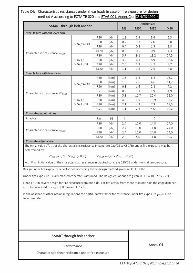
Table C4: Characteristic resistances under shear loads in case of fire exposure for design
method A according to EOTA TR 020 and ETAG 001, Annex C or CEN/TS 1992‐4
SMART through bolt anchor Anchor size
M8 M10 M12 M16
Steel failure without lever arm
Characteristic resistance VRk,s,fi
S‐KA / S‐KAK
R30 [kN] 1,3 2,3 3,6 5,3
R60 [kN] 0,7 1,3 2,0 3,0
R90 [kN] 0,4 0,8 1,3 1,8
R120 [kN] 0,3 0,5 0,9 1,3
S‐KAH /
S‐KAH HCR
R30 [kN] 5,7 9,1 13,2 24,5
R60 [kN] 3,9 6,1 8,9 16,6
R90 [kN] 2,0 3,2 4,7 8,7
R120 [kN] 1,1 1,8 2,6 4,8
Steel failure with lever arm
Characteristic resistance M0Rk,s,fi
S‐KA / S‐KAK
R30 [Nm] 1,8 3,6 6,4 16,2
R60 [Nm] 1,3 2,6 4,6 11,7
R90 [Nm] 0,8 1,6 2,8 7,2
R120 [Nm] 0,6 1,1 1,9 4,9
S‐KAH /
S‐KAH HCR
R30 [Nm] 5,8 11,7 20,4 52,0
R60 [Nm] 4,0 7,9 13,9 35,2
R90 [Nm] 2,1 4,2 7,3 18,5
R120 [Nm] 1,1 2,3 4,0 10,2
Concrete pryout failure
k‐factor k(3) [‐] 1 2
Characteristic resistance VRk,cp,fi
R30 [kN] 2,4 10,0 14,8 24,0
R60 [kN] 2,4 10,0 14,8 24,0
R90 [kN] 2,4 10,0 14,8 24,0
R120 [kN] 2,0 8,0 11,8 19,2
Concrete edge failure
The initial value V0Rk,c,fi of the characteristic resistance in concrete C20/25 to C50/60 under fire exposure may be
determined by:
V0Rk,c,fi = 0,25 x V0
Rk,c (≤ R90) V0Rk,c,fi = 0,20 x V0
Rk,c (R120)
with V0Rk,c initial value of the characteristic resistance in cracked concrete C20/25 under normal temperature.
Design under fire exposure is performed according to the design method given in EOTA TR 020.
Under fire exposure usually cracked concrete is assumed. The design equations are given in EOTA TR 020 § 2.2.1.
EOTA TR 020 covers design for fire exposure from one side. For fire attack from more than one side the edge distance
must be increased to cmin ≥ 300 mm and ≥ 2 x hef.
In the absence of other national regulations the partial safety factor for resistance under fire exposure γM,fi = 1,0 is
recommended.
SMART through bolt anchor
Performance
Displacements under tension and shear loads
Annex C5
ETA‐10/0472 of 9/5/2017 ‐ page 13 of 14
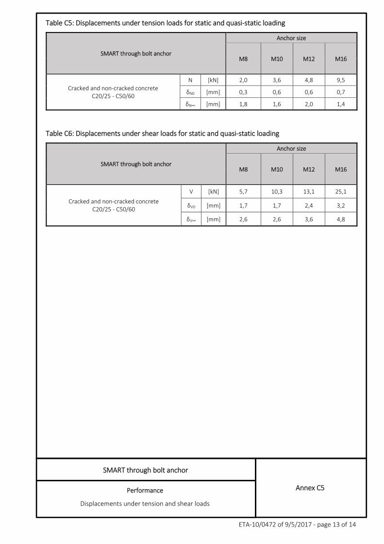
Table C5: Displacements under tension loads for static and quasi‐static loading
SMART through bolt anchor
Anchor size
M8 M10 M12 M16
Cracked and non‐cracked concrete C20/25 ‐ C50/60
N [kN] 2,0 3,6 4,8 9,5
δN0 [mm] 0,3 0,6 0,6 0,7
δN∞ [mm] 1,8 1,6 2,0 1,4
Table C6: Displacements under shear loads for static and quasi‐static loading
SMART through bolt anchor
Anchor size
M8 M10 M12 M16
Cracked and non‐cracked concrete C20/25 ‐ C50/60
V [kN] 5,7 10,3 13,1 25,1
δV0 [mm] 1,7 1,7 2,4 3,2
δV∞ [mm] 2,6 2,6 3,6 4,8
SMART through bolt anchor
Performance
Characteristic tension and shear resistances under seismic action,
Performance Category C1
Annex C6
ETA‐10/0472 of 9/5/2017 ‐ page 14 of 14
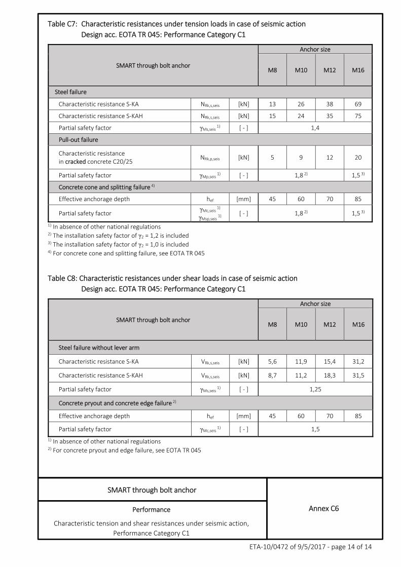
Table C7: Characteristic resistances under tension loads in case of seismic action
Design acc. EOTA TR 045: Performance Category C1
SMART through bolt anchor
Anchor size
M8 M10 M12 M16
Steel failure
Characteristic resistance S‐KA NRk,s,seis [kN] 13 26 38 69
Characteristic resistance S‐KAH NRk,s,seis [kN] 15 24 35 75
Partial safety factor γMs,seis 1) [ ‐ ] 1,4
Pull‐out failure
Characteristic resistance in cracked concrete C20/25
NRk,p,seis [kN] 5 9 12 20
Partial safety factor γMp,seis 1) [ ‐ ] 1,8 2) 1,5 3)
Concrete cone and splitting failure 4)
Effective anchorage depth hef [mm] 45 60 70 85
Partial safety factor γMc,seis
1)
γMsp,seis 1)
[ ‐ ] 1,8 2) 1,5 3)
1) In absence of other national regulations 2) The installation safety factor of γ2 = 1,2 is included 3) The installation safety factor of γ2 = 1,0 is included 4) For concrete cone and splitting failure, see EOTA TR 045
Table C8: Characteristic resistances under shear loads in case of seismic action
Design acc. EOTA TR 045: Performance Category C1
SMART through bolt anchor
Anchor size
M8 M10 M12 M16
Steel failure without lever arm
Characteristic resistance S‐KA VRk,s,seis [kN] 5,6 11,9 15,4 31,2
Characteristic resistance S‐KAH VRk,s,seis [kN] 8,7 11,2 18,3 31,5
Partial safety factor γMs,seis 1) [ ‐ ] 1,25
Concrete pryout and concrete edge failure 2)
Effective anchorage depth hef [mm] 45 60 70 85
Partial safety factor γMc,seis 1) [ ‐ ] 1,5
1) In absence of other national regulations 2) For concrete pryout and edge failure, see EOTA TR 045