Embed Size (px)
Citation preview
Aalborg Universitet
Evaluation of Core Loss in Magnetic Materials Employed in Utility Grid AC Filters
Beres, Remus Narcis; Wang, Xiongfei; Blaabjerg, Frede; Bak, Claus Leth; Matsumori,Hiroaki; Shimizu, ToshihisaPublished in:Proceedings of the 31st Annual IEEE Applied Power Electronics Conference and Exposition (APEC)
DOI (link to publication from Publisher):10.1109/APEC.2016.7468298
Publication date:2016
Document VersionEarly version, also known as pre-print
Link to publication from Aalborg University
Citation for published version (APA):Beres, R. N., Wang, X., Blaabjerg, F., Bak, C. L., Matsumori, H., & Shimizu, T. (2016). Evaluation of Core Lossin Magnetic Materials Employed in Utility Grid AC Filters. In Proceedings of the 31st Annual IEEE Applied PowerElectronics Conference and Exposition (APEC) (pp. 3051-3057). IEEE Press.https://doi.org/10.1109/APEC.2016.7468298
General rightsCopyright and moral rights for the publications made accessible in the public portal are retained by the authors and/or other copyright ownersand it is a condition of accessing publications that users recognise and abide by the legal requirements associated with these rights.
? Users may download and print one copy of any publication from the public portal for the purpose of private study or research. ? You may not further distribute the material or use it for any profit-making activity or commercial gain ? You may freely distribute the URL identifying the publication in the public portal ?
Take down policyIf you believe that this document breaches copyright please contact us at [email protected] providing details, and we will remove access tothe work immediately and investigate your claim.
Downloaded from vbn.aau.dk on: August 14, 2019

Evaluation of Core Loss in Magnetic Materials Employed in Utility Grid AC Filters
Remus Beres, Xiongfei Wang, Frede Blaabjerg, Claus Leth Bak
Department of Energy Technology Aalborg University Aalborg, Denmark
[email protected], [email protected], [email protected], [email protected]
Hiroaki Matsumori, Toshihisa Shimizu Dept. of Electrical Engineering Tokyo Metropolitan University
Tokyo, Japan [email protected], [email protected]
Abstract—Inductive components play an important role in filtering the switching harmonics related to the pulse width modulation in voltage source converters. Particularly, the filter reactor on the converter side of the filter is subjected to rectangular excitation which may lead to significant losses in the core, depending on the magnetic material of choice and current ripple specifications. Additionally, shunt or series reactors that exists in LCL or trap filters and which are subjected to sinusoidal excitations have different specifications and requirements. Therefore, the core losses of different magnetic materials adopted in utility grid ac filters have been investigated and measured for both sinusoidal and rectangular excitation, with and without dc bias condition. The core loss information can ensure cost-effective passive filter designs and may avoid trial-error design procedures of the passive components parameters.
Keywords—core loss; harmonic filters; passive components; PWM inverters.
I. INTRODUCTION Inductive components are a critical component in today’s
power electronics based power systems [1]. To achieve lower size and cost, high-order passive filters [2] are preferred in general, to limit the switching harmonics from Pulse Width Modulation (PWM). Passive filters solutions for voltage-source converters (VSC) may include the LCL [3] or trap filters [4], [5]. To reduce the size and cost of the passive filters, the total stored energy in the inductive components is minimized [6]–[9]. However, lower inductances in the filter, results in higher current ripple which adds loss to the overall system, decreasing the efficiency [10].
Particularly, the filter reactor on the converter side of the filter is subjected to high frequency rectangular excitation which may lead to significant losses in the core [11], [12], depending on the magnetic material of choice [13] and current ripple specifications [10]. Additionally, shunt or series reactors that exists in LCL or trap filters and which are subjected to sinusoidal excitation have different specifications and requirements compared to the reactor on the converter side of the filter. Then, the difficulties to describe the associated frequency-dependent core losses, especially under
the non-sinusoidal excitation [11], [14] and dc bias condition [11], leads to rather conservative design approach of passive filters. In general, there is a gap between the parameter selection of the passive filters which are well documented in literature [3], [6], [10] and the physical design of passive components which can be used for filter optimization [12]. Therefore, in most situations, trial and error based passive filter design methods cannot be avoided.
In the case of single-phase inductors, recent works [11], [15] established improved calculation methods of the core losses under rectangular excitation waveform and dc bias with good accuracies. For three-phase inductors, a core loss calculation and a measurement method was developed in [16]. However, since these models are mainly based on a loss map which stores the actual measurements of the core loss as a function of the dc pre-magnetization, flux density ripple and operating frequency, it is more difficult to be used and extended to other materials without additional measurements. Additionally, the core loss under sinusoidal excitation given in datasheets with Steinmetz coefficients are typically not accurate for low operating frequencies (lower than 20 kHz), which is the case of utility grid ac filters. Since the core losses under rectangular excitation with and without dc bias are not yet available in datasheets, it became more difficult to design PWM reactors with reasonable knowledge about power loss. Therefore, the core loss under sinusoidal and rectangular excitation with and without dc bias condition is measured and reported for several core materials which can be used for the physical design of the passive filters. The core losses are reported as a function of the magnetic field strength which can be used directly to relate the loss information with the current ripple in the reactors. The core loss information can ensure cost-effective passive filter designs and may avoid trial-error design procedures of the passive components parameters.
The operating principle of passive filters used in ac applications is described in the next section. The size and loss characteristics of typical magnetic cores and their applications to ac filter design are briefly summarized afterwards. The actual measurements of the core losses for the investigated magnetic materials conclude this paper.
This work was supported by European Research Council (ERC) under the European Union’s Seventh Framework Program (FP/2007-2013) /ERC Grant Agreement n. [321149-Harmony].
978-1-4673-9550-2/16/$31.00 ©2016 IEEE 3051
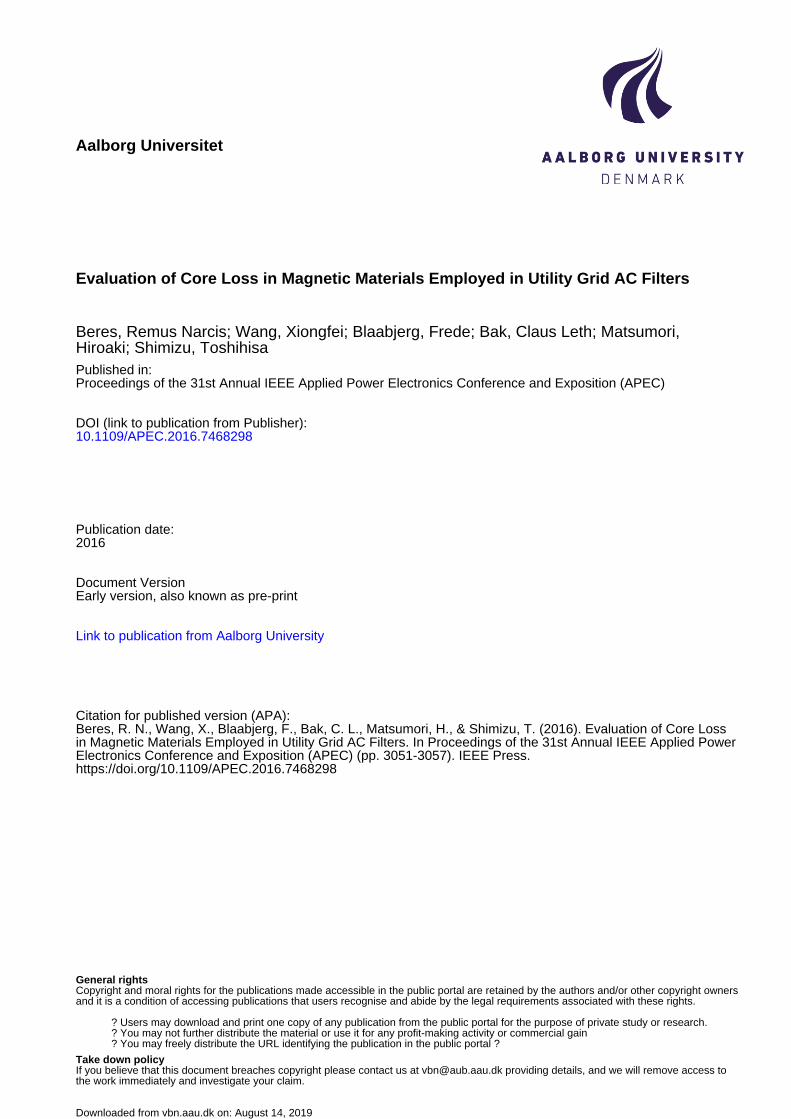
II. DESCRIPTION OF AC FILTERS Typical ac filters employed in utility grid applications are
illustrated in Fig. 1 where L1 is the reactor on the VSC output (PWM reactor); L2 is the reactor on the grid side (series reactor); Lf and Cf are the filter shunt reactor and capacitor, respectively. The circuit in Fig. 1 assumes ideal passive components. The parasitic resistances or the detailed model of the passive components can be lumped into the complex impedances Z1, Z2 and Z3 with Zg being the impedance of the utility grid. Note that all the impedances are time and frequency-dependent and vary with the operating point of the converter and utility grid.
The high-order filter illustrated in Fig. 1 and delimited by the VSC output and the Point of Common Coupling (PCC) can be used to analyze the three types of reactors, independently. The input (i1) and output current (i2) of the filter can be written as function of the admittance system as:
1 11 121 2
2 21 22
i Y Yv v
i Y Y⎡ ⎤ ⎡ ⎤ ⎡ ⎤
= +⎢ ⎥ ⎢ ⎥ ⎢ ⎥⎣ ⎦ ⎣ ⎦ ⎣ ⎦
(1)
where v1 and is v2 are the output converter voltage and PCC voltage, respectively (phase to ground voltages); Y11 and Y22 are the primary and secondary short-circuit admittances, respectively; Y12 and Y21 are the transfer short-circuit admittances. The admittance system in (1) applies to current controlled VSCs. For filter design, the high frequency content in the PCC voltage (v2) can be assumed very low therefore it can be neglected from (1). As result, the high frequency harmonic content is given mainly form the PWM harmonics found in the converter output voltage (v1) and which should be minimized by the filter.
The amplitude of the fundamental current (I1h) of the VSC can be calculated as:
11 1
23
VSCh
h h
SIV =
= (2)
where SVSC is the rated apparent power of the VSC and V1h is the amplitude of the converter voltage fundamental component. I1h can be used to derive the inductance and current ratings needed for the physical design of the three types of reactors.
A. PWM reactor PWM filters are mainly represented by a reactor subjected
to rectangular excitation (which depends on the PWM method) of frequencies up to tens of kHz. The time varying switched excitation waveform of the PWM reactor can be written in the general form as [17]:
Figure 1: One-phase schematic of typical AC filters employed in utility grids.
( ) ( ) ( ){ }
( ) ( ){ }
( ) ( ){ }
000 0 0 0
1
0 01
0 01
0
cos sin2
cos sin
cos sin
n nn
m c m cm
mn c mn cm n
n
AF t A n t B n t
A m t B m t
A m n t B m n t
ω ω
ω ω
ω ω ω ω
∞
=
∞
=∞ ∞
= =−∞≠
= + +
+ +
+ + + +⎡ ⎤ ⎡ ⎤⎣ ⎦ ⎣ ⎦
∑
∑
∑∑
(3)
where A00 is the dc offset of the time varying signal, the first summation term represents the fundamental and baseband harmonics, the second summation term represents the carrier harmonics while the third summation term represents the carrier sideband harmonics. For a given PWM method, the magnitude of [mωc+nω0] harmonic voltage components can be found evaluating the double integral Fourier form [17]:
( ) ( )2
1 ,2
j mx nymn mn mnC A jB F x y e dxdy
π π
π ππ+
− −
= + = ∫ ∫ (4)
where F(x,y) is the switched waveform for one fundamental period, ωc is the carrier frequency and x=ωct, ω0 is the fundamental frequency and y=ω0t, m is the carrier index (ωc/ω0); n is the baseband index. The analytical solutions of the Fourier coefficients for the most known PWM methods for single and three phase inverters are given in [18].
Once the harmonic spectrum of v1 is known, the inductance and current rating (to avoid saturation) of the PWM reactor can be found. The inductance of the PWM reactor is limited by the current ripple requirement. The inductance L1 at the rated current is directly proportional with the dc-link voltage (Vdc) and inversely proportional with the maximum current ripple (Δi1pk) and switching frequency (fsw):
11
dc
pk sw
VL
r i fΔ
(5)
For a two-level three-phase VSC which uses the conventional Space Vector Modulation (SVM) (assuming a modulation index of 0.9), the ripple factor r = 24 [2] while for unipolar modulation in the case of a single-phase VSC, r = 8. However, to evaluate the time varying current ripple, it is required to analyze (1) around the switching frequencies and multiples. Above the resonance frequency of the system (ωres), the individual current harmonics in the PWM reactor that contributes to the current ripple can be found as:
0
11
0 1res
resres
hh h h
h
VIh L ω
ω
ω >
=
=
(6)
Then, the time varying current ripple waveform results as:
( )1 1 0( ) cosres
n
r hh h
i t I h tω>
= ∑
(7)
3052

The current rating to design the PWM reactor in order to avoid the core saturation can be found as:
( ) ( )( ) max1 11 1
1
max cL pk r
A B NI i t i tL
= + = (8)
where i11(t)=I1hcos(ω0t); the maximum operating flux density of the reactor is chosen lower than the saturation flux density of the magnetic core (Bmax < Bsat); Ac is the cross-section area of the core and N is the number of turns. The key trade-off in the PWM reactor design is the optimum selection (to minimize loss) of the ripple current for a given magnetic material. The current ripple creates minor hysteresis loops related to the switching frequency modulation and are the major part of the core loss [16]. The core loss of each minor loop corresponding to each switching interval can be characterized and measured with a dc buck-chopper circuit and a B-H analyzer [11]. A smaller part of the core loss in a PWM reactor is related to the fundamental output frequency of the VSC, which can be measured with low frequency sinusoidal excitation.
B. Shunt Reactor Shunt filters can be used for power factor correction,
voltage support or harmonic compensation. The common operating frequencies of ac reactors in a harmonic shunt filter can be up to 3 kHz [19]. Shunt filtering can be also used to cancel out the ripple current from VSCs, especially in trap filter configurations [20]. For trap filters, the operating frequency of the reactors can reach tens of kHz [21]. The core loss of a shunt filter reactor can be measured with a high frequency (equal to the tuned frequency) and small amplitude sinusoidal voltage. A fixed inductance value is desirable in shunt reactors, in order to avoid de-tuning of the filter during operation. The shunt reactor inductance can be derived as:
21
ft f
LCω
= (9)
The current rating of the shunt reactor must consider the fundamental current given by the impedance of the shunt capacitor and the high frequency ripple current given in (7) as:
( ) ( )( ) max1 1max c
Lfpk Cf rf
A B NI i t i tL
= + = (10)
where iCf1(t)= ω0CfV1cos(ω0t) is the fundamental current in the shunt reactor.
C. Series Reactor Sine wave filters or series reactors used to smoothen out
the grid current are driven by sinusoidal voltages at the fundamental grid frequency. Since full current (rated current of the VSC) have to be handled by the reactors, high energy storage capability and low cost is preferable for this type of filter.
III. APPLICATION OF MAGNETIC MATERIALS TO AC FILTER DESIGN
A. Magnetic Materials Properties The key properties of common magnetic materials are
illustrated in Table I. The magnetic cores can be divided in two categories: with distributed gap (powder cores) and with physical gap (cut cores). The B-H curves of the cheapest materials from the two categories are illustrated in Fig. 2.
Figure 2: B-H dependence of laminated Fe-Si and Fe powder.
Table I: Comparison of different magnetic core materials [22]
Materials Permeability (µ) Bsat (T) Core Loss DC Bias Relative
Cost Temp.
Stability Curie Temp.
(ºC)
Powder
MPP (Ni-Fe-Mo) 14-200 0.7 Lower Better High Best 450
High Flux (Ni-Fe) 26-160 1.5 Low Best Medium Better 500
Sendust (Fe-Si-Al) 26-125 1 Low Good Low Good 500
Mega Flux (Fe-Si) 26-90 1.6 Medium Best Low Better 700
Iron (Fe) 10-100 1 High Poor Lowest Poor 770
Strip (Gapped)
Silicon Steel (Fe-Si)
Up to 10000
1.8 High Best Lowest Good 740
Amorphous (Fe-Si-Bo) 1.5 Low Better Medium Good 400
(Gapped) Ferrite (Mn-Zn) 0.45 Lowest Poor Lowest Poor 100~300
3053

The cut cores have linear B-H dependence for B<0.95Bsat (constant permeability) and exhibits a hard saturation while the powder cores have a non-linear B-H dependence (decreased permeability with increased excitation) and exhibits soft saturation. Due to the distributed air gap, powder cores can reach a maximum magnetic field strength (Hm) in the range of 10-80 kA/m. On the other hand, the ungapped laminated steel or ferrites class can reach about 1 kA/m. By adding air gap, the H range can be increased, leading to higher storage capability.
The permeability (µ) dependence (or inductance decrease) as function of the dc bias magnetic field (H0) are illustrated in Fig. 3 for magnetic core samples of equal volume (except the ferrite which is 1.5 times larger than others). The inductance factor (AL) or the permeance of the core samples is defined as:
0@ 0 2
1cL A
e
L AA
lNμ
= =ℜ
= (11)
m eH lN
I= (12)
where L0 is the inductance of the core at zero current, Ac is the core cross-section area, le is the effective core magnetic path length and N is the number of turns, which can be written as in (12) as a function of Hm, le and the inductor current I.
B. Selection of Magnetic Material Based on Energy Storage and DC Bias Charactersitics For designing reactors, it is reasonable to assume a 70% of
the initial permeability for powder cores, in order to “fully” exploit the stored energy capability. For gapped cores it is considered to be around 95-100% of the initial permeability in order to avoid saturation. Assuming a 1 mm diameter round wire for the inductor windings (with a current density of 5A/mm2) and considering a fixed Hmax to avoid saturation, the number of turns is readily available from (12). Since the inductance factor is fixed for a given material, the inductance value is given only by the number of turns, assuming fixed current and Hmax. By using the inductance factor from Fig. 3 and using (11), the inductance value can be found. In Table II, L, N and the energy storage capability (LI2) of the core samples are shown assuming 95% of the initial permeability at rated current for cut cores and 70% for the powder cores (including 95% and 50% for the Mega Flux core).
0
20
40
60
80
100
0 2000 4000 6000 8000 10000
%µ
H0 [A/m] a)
0
20
40
60
80
100
0 10000 20000 30000%
µH0 [A/m] b)
Figure 3: Relative permeability vs. H0 curves, measured with a Wayne Kerr Precision Magnetic Analyzer 3260B at 500 Hz and 10 V drive voltage for: a) cut cores with physical gap (data not available in datasheets); b) powder materials with distributed
gap (within ±10 % deviation from the datasheet values).
Eq. (11)-(12) are used only to evaluate the relative size of the inductors. The window utilization factor (Ku) has been assumed 0.45. However, as can be seen from Table II, the number of turns that lead to Ku=0.45 is exceeded for some reactors design. To avoid excessive temperature rise in reactors, the number of turns should be decreased or a larger core should be adopted. From the considered magnetic cores, the silicon steel and amorphous offers the best cost/energy storage trade-offs. For the powder cores, it is possible to increase the energy storage capability by adopting lower initial permeability which in turn will increase the size of the winding and associated cost/loss.
Table II: Design example of sample inductor with different materials
Samples
Ferrite (E55 N87)
Amorphous (AMCC10)
Fe-Si (SC10)
Iron (SK-36M)
High Flux (CH571)
Mega Flux (CK571)
MPP (CM571)
Sendust (CS571)
lg=0.4 mm
lg=0.8 mm
lg=0.4 mm
lg=0.8 mm
lg=0.4mm
lg=0.8mm
70 µ%
70 µ%
95 µ%
70 µ%
50 µ%
70 µ%
70 µ%
Hm (kA/m) 1.2 2.3 3 6 5 8.7 1.8 11 3 9 13 13 12
le (mm) 124 138 138 142.4 125 125 125 125 L (mH) 0.6 1.95 4.06 10.3 12.2 22 0.5 11 1.23 8.13 12 6.67 5.41
I (A) 4 4 4 4 4 4 4 4 4 4 4 4 4 N 32 73 105 210 175 300 65 350 96 287 414 414 382
LI2 (mHA2) 10 30 60 160 190 340 8 170 19 125 186 100 83 N (Ku=0.45) 185 220 220 400 300 300 300 300
3054
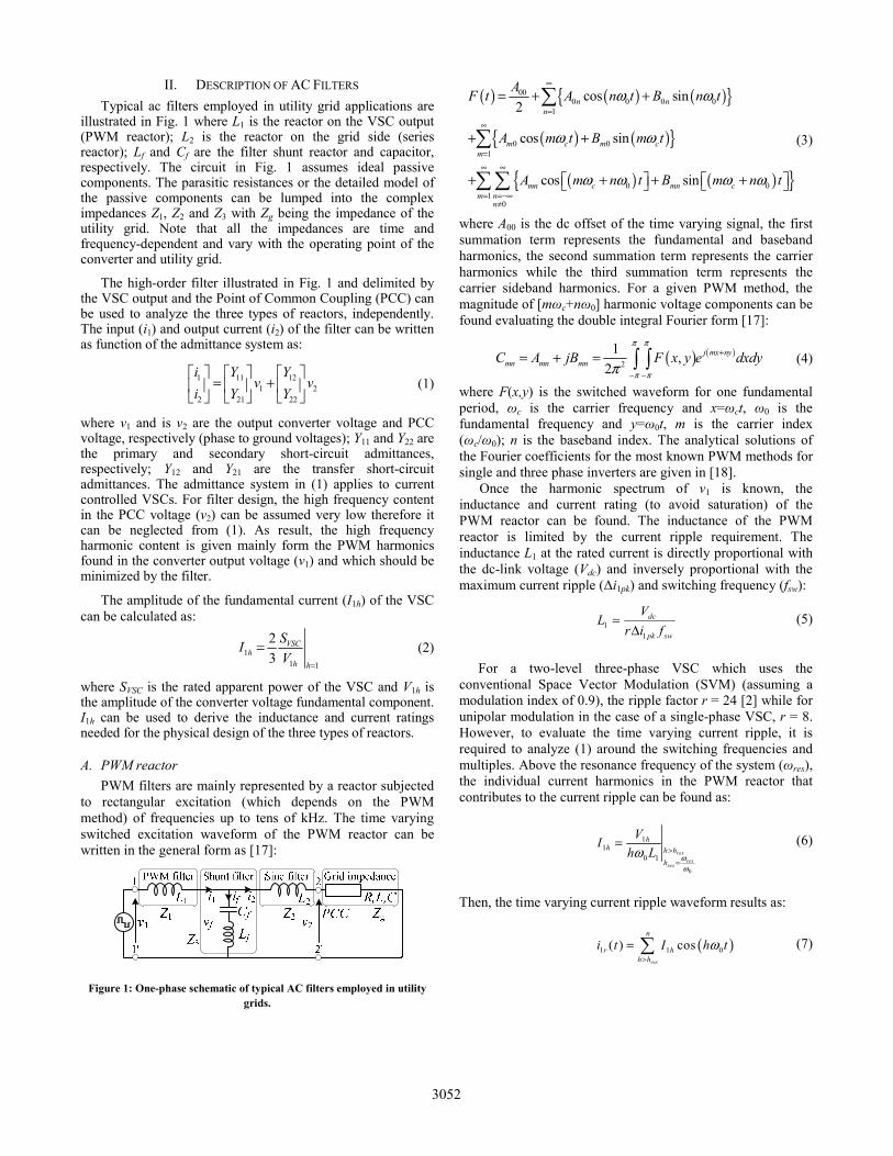
IV. EVALUATION OF CORE LOSS The core loss per volume (Pcv) for sinusoidal and
rectangular excitation is measured with an IWATSU SY-8219 B-H analyzer. The core loss under dc-bias is measured with an IWATSU SY-8232 B-H analyzer and a dc-chopper. The magnetic core samples are shown in Fig. 4.
Figure 4: Magnetic core samples
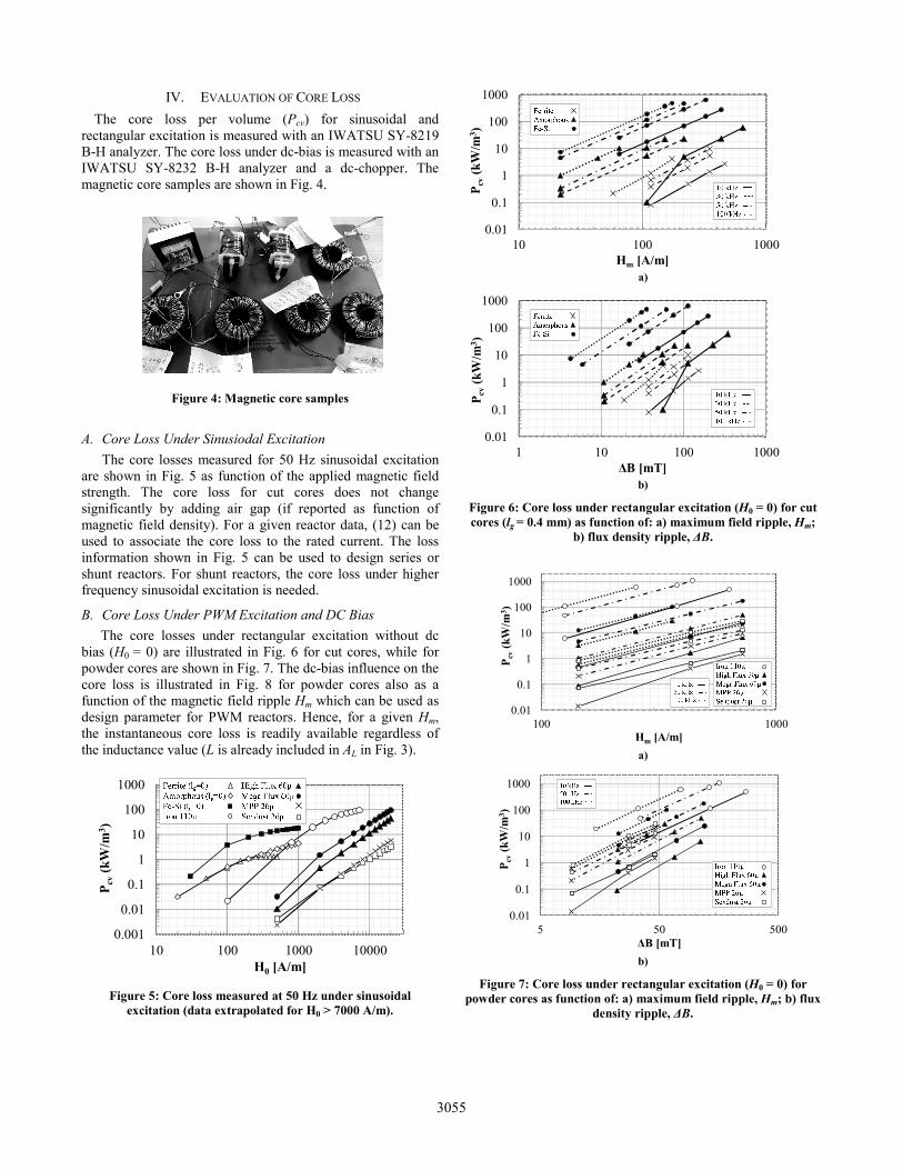
A. Core Loss Under Sinusiodal Excitation The core losses measured for 50 Hz sinusoidal excitation
are shown in Fig. 5 as function of the applied magnetic field strength. The core loss for cut cores does not change significantly by adding air gap (if reported as function of magnetic field density). For a given reactor data, (12) can be used to associate the core loss to the rated current. The loss information shown in Fig. 5 can be used to design series or shunt reactors. For shunt reactors, the core loss under higher frequency sinusoidal excitation is needed.
B. Core Loss Under PWM Excitation and DC Bias The core losses under rectangular excitation without dc
bias (H0 = 0) are illustrated in Fig. 6 for cut cores, while for powder cores are shown in Fig. 7. The dc-bias influence on the core loss is illustrated in Fig. 8 for powder cores also as a function of the magnetic field ripple Hm which can be used as design parameter for PWM reactors. Hence, for a given Hm, the instantaneous core loss is readily available regardless of the inductance value (L is already included in AL in Fig. 3).
0.001
0.01
0.1
1
10
100
1000
10 100 1000 10000
P cv
(kW
/m3 )
H0 [A/m]
Figure 5: Core loss measured at 50 Hz under sinusoidal excitation (data extrapolated for H0 > 7000 A/m).
0.01
0.1
1
10
100
1000
10 100 1000
P cv
(kW
/m3 )
Hm [A/m] a)
0.01
0.1
1
10
100
1000
1 10 100 1000
P cv
(kW
/m3 )
ΔB [mT] b)
Figure 6: Core loss under rectangular excitation (H0 = 0) for cut cores (lg = 0.4 mm) as function of: a) maximum field ripple, Hm;
b) flux density ripple, ΔB.
0.01
0.1
1
10
100
1000
100 1000
P cv
(kW
/m3 )
Hm [A/m] a)
0.01
0.1
1
10
100
1000
5 50 500
P cv
(kW
/m3 )
ΔB [mT] b)
Figure 7: Core loss under rectangular excitation (H0 = 0) for powder cores as function of: a) maximum field ripple, Hm; b) flux
density ripple, ΔB.
3055
1
10
100
1000
500 1500 2500 3500
P cv
(kW
/m3 )
Hm [A/m] a)
1
10
100
1000
0 5000 10000 15000 20000
P cv
(kW
/m3 )
H0 [A/m] b)
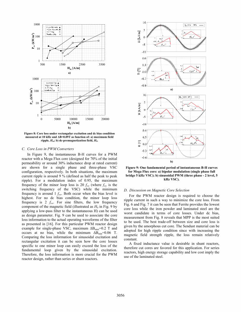
Figure 8: Core loss under rectangular excitation and dc bias condition measured at 10 kHz and ΔB=0.09T as function of: a) maximum field
ripple, Hm; b) dc-premagnetization field, H0.
C. Core Loss in PWM Converters In Figure 9, the instantaneous B-H curves for a PWM
reactor with a Mega Flux core (designed for 70% of the initial permeability or around 30% inductance drop at rated current) are shown for a single phase and three-phase VSC configuration, respectively. In both situations, the maximum current ripple is around 9 % (defined as half the peak to peak ripple). For a modulation index of 0.95, the maximum frequency of the minor loop loss is 20 fsw (where fsw is the switching frequency of the VSC) while the minimum frequency is around 1 fsw. Both occur when the bias level is highest. For no dc bias condition, the minor loop loss frequency is 2 fsw. For sine filters, the low frequency component of the magnetic field (illustrated as H0 in Fig. 9 by applying a low-pass filter to the instantaneous H) can be used as design parameter. Fig. 9 can be used to associate the core loss information to the actual operating waveforms of the filter as presented in [16]. For this particular PWM reactor design example for single-phase VSC, maximum ΔBmax=0.2 T and occurs at no bias, while the minimum ΔBmin=0.06 T. Comparing the loss information for sinusoidal excitation and rectangular excitation it can be seen how the core losses specific to one minor loop can easily exceed the loss of the fundamental loop given by the sinusoidal excitation. Therefore, the loss information is more crucial for the PWM reactor design, rather than series or shunt reactors.
a)
b)
Figure 9: One fundamental period of instantaneous B-H curves for Mega Flux core: a) bipolar modulation (single phase full
bridge 5 kHz VSC); b) sinusoidal PWM (three phase - 2 level, 5 kHz VSC).
D. Discussion on Magnetic Core Selection For the PWM reactor design is required to choose the
ripple current in such a way to minimize the core loss. From Fig. 6 and Fig. 7 it can be seen that Ferrite provides the lowest core loss while the iron powder and laminated steel are the worst candidate in terms of core losses. Under dc bias, measurement from Fig. 8 reveals that MPP is the most suited to be used. The best trade-off between size and core loss is given by the amorphous cut core. The Sendust material can be adopted for high ripple condition since with increasing the magnetic field strength ripple, the loss remain relatively constant.
A fixed inductance value is desirable in shunt reactors, therefore cut cores are favored for this application. For series reactors, high energy storage capability and low cost imply the use of the laminated steel.
3056

V. CONCLUSIONS In this paper, the core losses of several magnetic core
materials have been evaluated. From the investigated core materials, the laminated steel provides the best energy storage capability. However, it provides around 10 times higher core loss than the equivalent Mega Flux powder under rectangular excitation. Hence, the laminated steel is the best candidate for sine wave filters applications. The powder materials are good candidates for PWM filters, especially at high ripple current. The Amorphous core can be seen as the material with the best trade-off between size and loss. The Sendust core can ensure low loss under very high ripple condition. Ferrites do provide lower core loss, but the energy storage capability is the lowest. In addition, the permeability and loss of ferrites are highly dependent on temperature (the measurements reported in this paper are made at room temperature). For shunt filter applications, cut cores are preferred in order to keep a fixed inductance value as function of the dc bias.
REFERENCES [1] R. Teichmann, M. Malinowski, and S. Bernet, “Evaluation of
Three-Level Rectifiers for Low-Voltage Utility Applications,” IEEE Trans. Ind. Electron., vol. 52, no. 2, pp. 471–481, Apr. 2005.
[2] R. Beres, X. Wang, F. Blaabjerg, M. Liserre, and C. Bak, “Optimal
Design of High-Order Passive-Damped Filters for Grid-Connected Applications,” IEEE Trans. Power Electron., vol. 53, no. 4, pp. 1–1, 2015.
[3] M. Liserre, F. Blaabjerg, and S. Hansen, “Design and Control of an
LCL-Filter-Based Three-Phase Active Rectifier,” IEEE Trans. Ind. Appl., vol. 41, no. 5, pp. 1281–1291, Sep. 2005.
[4] J. M. Bloemink and T. C. Green, “Reducing Passive Filter Sizes
with Tuned Traps for Distribution Level Power Electronics,” in Proc. 14th European Conference on Power Electronics and Applications (EPE 2011), vol., no., pp.1-9, Aug. 30 2011-Sept. 1 2011.
[5] W. Wu, Y. He, and F. Blaabjerg, “An LLCL Power Filter for
Single-Phase Grid-Tied Inverter,” IEEE Trans. Power Electron., vol. 27, no. 2, pp. 782–789, Feb. 2012.
[6] K. Jalili and S. Bernet, “Design of LCL Filters of Active-Front-End
Two-Level Voltage-Source Converters,” IEEE Trans. Ind. Electron., vol. 56, no. 5, pp. 1674–1689, May 2009.
[7] G. Zeng, T. W. Rasmussen, and R. Teodorescu, “A novel optimized
LCL-filter designing method for grid connected converter,” in Proc. International Symposium on Power Electronics for Distributed Generation Systems, 2010, vol. 2, pp. 802–805.
[8] J. Verveckken, J. F. Silva, and J. Driesen, “Optimal analytic LCL
filter design for grid-connected voltage-source converter,” in Proc. of Eurocon 2013, 2013, no. July, pp. 823–830.
[9] L. Shen, G. Asher, P. Wheeler, and S. Bozhko, “Optimal LCL filter design for 3-phase Space Vector PWM rectifiers on variable frequency aircraft power system,” 2013 15th Eur. Conf. Power Electron. Appl. EPE 2013, 2013.
[10] Y. Jiao and F. C. Lee, “LCL Filter Design and Inductor Current
Ripple Analysis for a Three-Level NPC Grid Interface Converter,” IEEE Trans. Power Electron., vol. 30, no. 9, pp. 4659–4668, Sep. 2015.
[11] T. Shimizu and S. Iyasu, “A practical iron loss calculation for AC
filter inductors used in PWM inverters,” IEEE Trans. Ind. Electron., vol. 56, no. 7, pp. 2600–2609, 2009.
[12] J. Muhlethaler, M. Schweizer, R. Blattmann, J. W. Kolar, and A.
Ecklebe, “Optimal Design of LCL Harmonic Filters for Three-Phase PFC Rectifiers,” IEEE Trans. Power Electron., vol. 28, no. 7, pp. 3114–3125, Jul. 2013.
[13] M. S. Rylko, K. J. Hartnett, J. G. Hayes, and M. G. Egan, “Magnetic
Material Selection for High Power High Frequency Inductors in DC-DC Converters,” in Proc. IEEE Applied Power Electronics Conference and Exposition, 2009, pp. 2043–2049.
[14] K. Venkatachalam, C. R. Sullivan, T. Abdallah, and H. Tacca,
“Accurate prediction of ferrite core loss with nonsinusoidal waveforms using only Steinmetz parameters,” 2002 IEEE Work. Comput. Power Electron. 2002. Proceedings., no. June, 2002.
[15] J. Muhlethaler, J. Biela, J. W. Kolar, A. Ecklebe, M. Jonas, and A.
Ecklebe, “Core Losses Under the DC Bias Condition Based on Steinmetz Parameters,” IEEE Trans. Power Electron., vol. 27, no. 2, pp. 953–963, 2012.
[16] T. Shimizu, H. Matsumori, K. Takano, and H. Ishii, “Evaluation of
Iron Loss of AC Filter Inductor used in Three-Phase PWM inverters Based on an Iron Loss Analyzer (ILA),” IEEE Trans. Power Electron., vol. 8993, no. c, pp. 1–1, 2015.
[17] D. G. Holmes, “A general analytical method for determining the
theoreticalharmonic components of carrier based PWM strategies,” Conf. Rec. 1998 IEEE Ind. Appl. Conf. Thirty-Third IAS Annu. Meet. (Cat. No.98CH36242), vol. 2, no. 2, 1998.
[18] D. G. Holmes and T. A. Lipo, Pulse Width Modulation for Power
Converters: Principles and Practice. John Wiley & Sons, 2003. [19] J.C. Das, Power System Harmonics and Passive Filter Designs.
Piscataway, NJ 08854: Wiley-IEEE Press, 2015. [20] Y. Patel, D. Pixler, and A. Nasiri, “Analysis and design of TRAP
and LCL filters for active switching converters,” 2010 IEEE Int. Symp. Ind. Electron., pp. 638–643, Jul. 2010.
[21] J. Xu, J. Yang, J. Ye, Z. Zhang, and A. Shen, “An LTCL Filter for
Three-Phase Grid-Connected Converters,” IEEE Trans. Power Electron., vol. 29, no. 8, pp. 4322–4338, Aug. 2014.
[22] CSC catalog, “Magnetic Powder Cores.”, ver. 13.
3057