Embed Size (px)
Citation preview

2018 03 26 원종호
Evaluation of tensile properties using IIT
2
Contents
Background
POSCO project
- Evaluation of dynamic tensile property
Yield properties of PE pipe
3
Introduction
-Suitability of new material
-Degradation
-Accident amp damage analysis
Need for nondestructive technique
to evaluate material properties
at in-field
-Verification of feasibility
-Life predictionsafety assessment
-Construction of material DB
4
Introduction
Deformation
Fracture
σYS UTS n E
KIC JIC δIC
Destructive
How can I measure the mechanical properties
I am working Do not touch
5
Introduction
Specimens for tensile test Specimens for fracture test
Not applicable for small scale testing
Large scale testing
6
Introduction
Convenient
In-situ amp In-field System
Non-destructive amp Local test
Simple amp fast
7
Introduction
Ac
Hardness
Elastic modulus
CAPH max=
Ceff A
SE2π
=
Plastic deformation
Elastic deformation
8
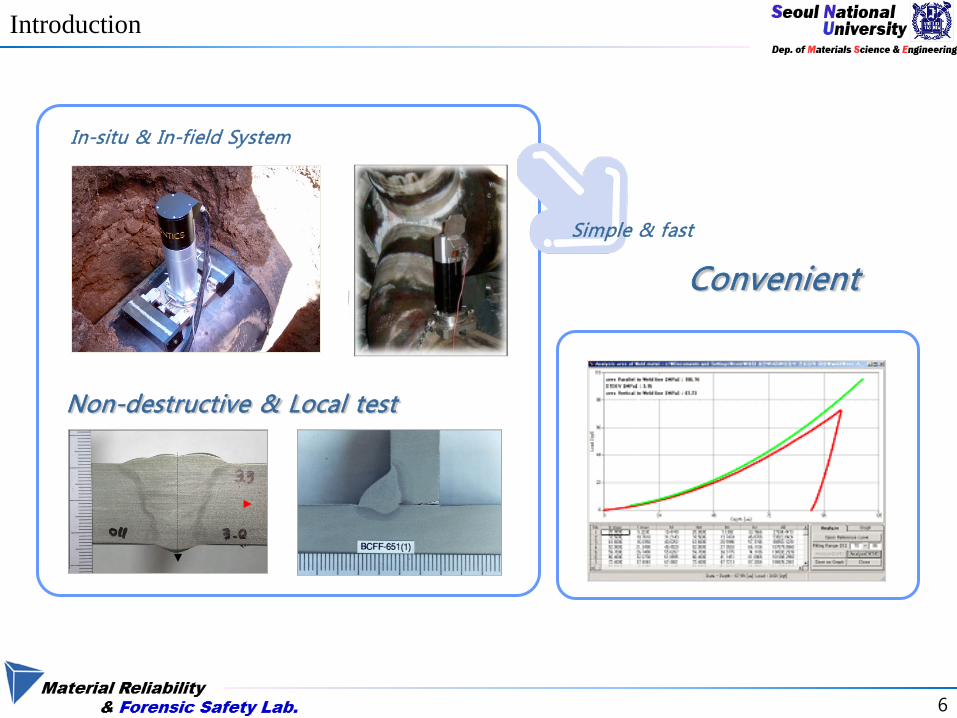
Algorithm for strength evaluation
diams Step 1Determining contact areataking into considerationplastic pile-upsink-in
SphericalIndentation
Stress and StrainState in Material
=
Rhnf
hh max
ITc
pile
diams Step 2Defining stress and strain statein materials underneath spherical indenteras representative stress and strain
c
maxT A
F1Ψ
σ = θξε tan=T
diams Step 3 amp 4Fitting to constitutive equation andevaluating tensile properties
True strain εΤ
True
stre
ss σ
Τ
σ=E(ε-0002) σ=Kεn
Representative stress-strain points
E
Instrumented indentation testwith a spherical indenter
Tensile propertiesTensile properties
σy IT σu IT nIT EIT
Force-depth curveof multiple unloadings
9
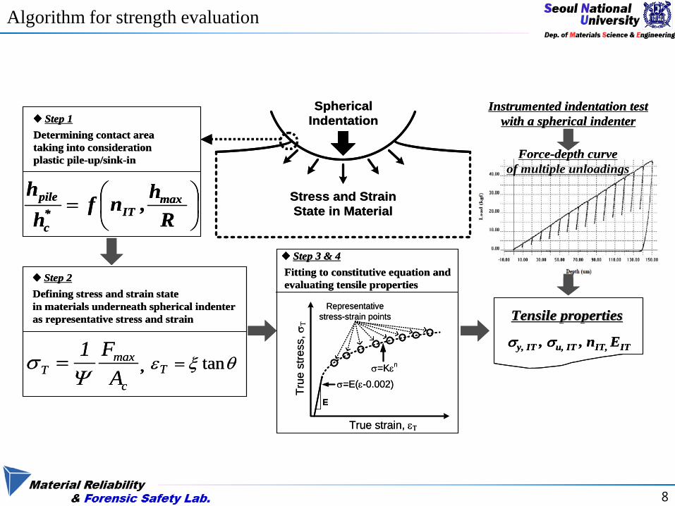
Step 1
Reference plane
Elastic deflection
dh-Plastic pile-upsink-in
pileh+
R
h c h d
h max
h pile
piledc hhhh +minus= max
SLhd
maxε= ) ( max
Rhnfhpile =
-WC Oliver amp GM Pharr J Mater Res (1992) -SH Kim et al Mater Sci Eng A (2006)
10
Step 2
Indentation depth increases Stress and strain increase
γ γ
Representative Stress Definition
Ψ=σR
mPΨ Constraint Factor (about 3)
2max
cm a
LPπ
=
Representative Strain Definition
γααε tan)(1 2
=minus
=Ra
Rac
c
R
-DTabor The Hardness of Metals (1951) -JH Ahn et al JMR (2000)
11
Step 3
nKε=σ
h
L
Loading
Unloading
σ
ε
Indentation load-depth curve Derived stress-strain points
12
Step 4
)0020( minus= yny EK εε
True
stre
ss
True strain
Yield strength
AL σ=
εdA
dAd=minus=
ll
σσd
AdA
=minus
σεσ
=dd
Tensile strength
nu =ε
13
POSCO project
(Evaluation of dynamic tensile property)
14
background
Room Temperature Low Temperature
Strain rate range 0001s 1s 10s 100s 200s
Schematic diagram of strain rate regimes
Dynamic strain rage 100 ~ 104 s
15
Definition of strain rate
Representative stress-strain definition (Expanding Cavity Model)
RhRh
Ra 222020 minus
==ε21
caL
πψσ =
Representative Stress Representative Strain
indentation strain rate (Spherical indenter)
- Representative strain definition RhRh
Ra 222020 minus
==ε
- indentation strain rate dt
dεε =amp )( VRhfdt
d=
εhc depth R indenter radius
V indentation speed
16
Definition of strain rate
4 6 8 10 12 14 16 18 20 22 2404
05
06
07
08
09
10
11
stra
in ra
te [
s]
h [um]
Dynamic range (100 ~ )
rarr 압입 깊이 별 strain rate 감소
Change of strain rate
according to indentation depth
0 20 40 60 80 100 120 140 160
02
04
06
08
10
12
14 strain rate=constant strain rate=changed
V[m
mm
in]
Depth[um]
example Indentation strain rate = 001
17
Result
000 005 010 015 020 0250
100
200
300
400
500
600
700
Tensile_Static Tensile_01s Tensile_02s Tensile_1s Indentation_Static Indentation_001s Indentation_005s
True
stre
ss[M
Pa]
True strain
[S-S curve comparison]
Confirming tendency of s-s curve according to strain rate
18
Equipment improvement
Minute control
AIS3000 Hardware
0 1 2 3 4 5 6 7 8 9 1000
02
04
06
08
10
Inde
ntat
ion
stra
in ra
te [
s]
indentation speed [mmmin]
19
Dynamic hardening factor
σd f(εp) = σs f(εp) middot DHF
DHF Dynamic Hardening Factor
Experimental constant (D)
[Joon mo Choung Dynamic hardening behaviors of various marine structural steels
considering dependencies on strain rate and temperature 2013]
20
Change in DHF
1E-3 001 01 1 10
10
11
12
13 SM400 (σ0=2967MPa)
DHF
Strain Rate [s]1E-3 001 01 1 10
10
11
12
13 SM490 (σ0=3421MPa)
DHF
Strain Rate [s]
SM400 SM490
Change in DHF with strain rate (tensile test)
01 1
100
101
102
103
104
105
106
107 SM490 σ0 = 3213 MPa
DHF
Strain Rate [s]01 1
100
101
102
103
104
105
106
107 SM400 σ0= 2664MPa
DHF
Strain Rate [s]
SM400 SM490
Change in DHF with strain rate (IIT)
21
Yield properties of PE pipe
22
Introduction
Gas Water Sewage Chemicals
In Industrial In Metropolitan
bull Corrosion amp Chemical resistance
bull Long life amp Life cycle cost savings
bull Leak free joint
bull Light weight
bull Flexibiility
bull High ductility
bull Easy installation
bull Fatigue amp Seismic resistance
Advantages of PE
23
Indenter
Background
Issue (Application to PE)
R
d1
R
d2
θ1
θ2
d
Residual Indent(top view)
Ψ=σR
mP Ψ Constraint Factor (about 3)
γε sin250=T
Representation
True strain εΤ
True
stre
ss σ
Τ
σ=E(ε-0002) σ=Kεn
Representative stress-strain points
E
In order to Evaluate Strength of Polyethylene Definition of strain rate on IIT is essential It is difficult to definite strain rate using spherical indenter Because the contact area is consistently changing during indentation
24
Indenter
Approach
Using flat-ended cylindrical indenter instead of spherical indenter
Characteristics
Indenter shape
Sharp Spherical
(Conventional representation)
Flat-ended cylindrical
No self-similarity Not keeping resemblance
during indentation X O O
Fixed contact area constant contact area during
indentation X X O
Closeness to compression test X O
25
Definition of strain
0
50
100
150
200
250
300
350
0 20 40 60 80 100
load
(kg
f)
depth (um)
a=250um
a=500um
a=1000um
Load-depth curve
00
05
10
15
20
25
30
00 01 02 03 04Pm
(G
Pa)
hR
a=250um
a=500um
a=1000um
Load rArr Pm h rArr hR
Normalization
hR can be ldquoRepresentativerdquo strain
26
Strain rate
Rh
r
bullbull
minus=χ
ε 1
From flat-ended indentation for creep test
Rhqr 21
bullbull
sdot=εA
hqr
bullbull
sdot= 2ε
q1 amp q2 are constant
[PMSargent Mater Sci Technol 1992] [JLu J Mech Phys Solids 2003]
Experimental approach
In progresshellip
27
28
(Indentation strain rate definition by Doener amp Nix )
Indentation strain rate
Indentation test parameter
Plastic zone expansion rate of indentation

2
Contents
Background
POSCO project
- Evaluation of dynamic tensile property
Yield properties of PE pipe
3
Introduction
-Suitability of new material
-Degradation
-Accident amp damage analysis
Need for nondestructive technique
to evaluate material properties
at in-field
-Verification of feasibility
-Life predictionsafety assessment
-Construction of material DB
4
Introduction
Deformation
Fracture
σYS UTS n E
KIC JIC δIC
Destructive
How can I measure the mechanical properties
I am working Do not touch
5
Introduction
Specimens for tensile test Specimens for fracture test
Not applicable for small scale testing
Large scale testing
6
Introduction
Convenient
In-situ amp In-field System
Non-destructive amp Local test
Simple amp fast
7
Introduction
Ac
Hardness
Elastic modulus
CAPH max=
Ceff A
SE2π
=
Plastic deformation
Elastic deformation
8
Algorithm for strength evaluation
diams Step 1Determining contact areataking into considerationplastic pile-upsink-in
SphericalIndentation
Stress and StrainState in Material
=
Rhnf
hh max
ITc
pile
diams Step 2Defining stress and strain statein materials underneath spherical indenteras representative stress and strain
c
maxT A
F1Ψ
σ = θξε tan=T
diams Step 3 amp 4Fitting to constitutive equation andevaluating tensile properties
True strain εΤ
True
stre
ss σ
Τ
σ=E(ε-0002) σ=Kεn
Representative stress-strain points
E
Instrumented indentation testwith a spherical indenter
Tensile propertiesTensile properties
σy IT σu IT nIT EIT
Force-depth curveof multiple unloadings
diams Step 1Determining contact areataking into considerationplastic pile-upsink-in
SphericalIndentation
Stress and StrainState in Material
=
Rhnf
hh max
ITc
pile
diams Step 2Defining stress and strain statein materials underneath spherical indenteras representative stress and strain
c
maxT A
F1Ψ
σ = θξε tan=T
diams Step 3 amp 4Fitting to constitutive equation andevaluating tensile properties
True strain εΤ
True
stre
ss σ
Τ
σ=E(ε-0002) σ=Kεn
Representative stress-strain points
E
Instrumented indentation testwith a spherical indenter
Tensile propertiesTensile properties
σy IT σu IT nIT EIT
Force-depth curveof multiple unloadings
9
Step 1
Reference plane
Elastic deflection
dh-Plastic pile-upsink-in
pileh+
R
h c h d
h max
h pile
piledc hhhh +minus= max
SLhd
maxε= ) ( max
Rhnfhpile =
-WC Oliver amp GM Pharr J Mater Res (1992) -SH Kim et al Mater Sci Eng A (2006)
10
Step 2
Indentation depth increases Stress and strain increase
γ γ
Representative Stress Definition
Ψ=σR
mPΨ Constraint Factor (about 3)
2max
cm a
LPπ
=
Representative Strain Definition
γααε tan)(1 2
=minus
=Ra
Rac
c
R
-DTabor The Hardness of Metals (1951) -JH Ahn et al JMR (2000)
11
Step 3
nKε=σ
h
L
Loading
Unloading
σ
ε
Indentation load-depth curve Derived stress-strain points
12
Step 4
)0020( minus= yny EK εε
True
stre
ss
True strain
Yield strength
AL σ=
εdA
dAd=minus=
ll
σσd
AdA
=minus
σεσ
=dd
Tensile strength
nu =ε
13
POSCO project
(Evaluation of dynamic tensile property)
14
background
Room Temperature Low Temperature
Strain rate range 0001s 1s 10s 100s 200s
Schematic diagram of strain rate regimes
Dynamic strain rage 100 ~ 104 s
15
Definition of strain rate
Representative stress-strain definition (Expanding Cavity Model)
RhRh
Ra 222020 minus
==ε21
caL
πψσ =
Representative Stress Representative Strain
indentation strain rate (Spherical indenter)
- Representative strain definition RhRh
Ra 222020 minus
==ε
- indentation strain rate dt
dεε =amp )( VRhfdt
d=
εhc depth R indenter radius
V indentation speed
16
Definition of strain rate
4 6 8 10 12 14 16 18 20 22 2404
05
06
07
08
09
10
11
stra
in ra
te [
s]
h [um]
Dynamic range (100 ~ )
rarr 압입 깊이 별 strain rate 감소
Change of strain rate
according to indentation depth
0 20 40 60 80 100 120 140 160
02
04
06
08
10
12
14 strain rate=constant strain rate=changed
V[m
mm
in]
Depth[um]
example Indentation strain rate = 001
17
Result
000 005 010 015 020 0250
100
200
300
400
500
600
700
Tensile_Static Tensile_01s Tensile_02s Tensile_1s Indentation_Static Indentation_001s Indentation_005s
True
stre
ss[M
Pa]
True strain
[S-S curve comparison]
Confirming tendency of s-s curve according to strain rate
18
Equipment improvement
Minute control
AIS3000 Hardware
0 1 2 3 4 5 6 7 8 9 1000
02
04
06
08
10
Inde
ntat
ion
stra
in ra
te [
s]
indentation speed [mmmin]
19
Dynamic hardening factor
σd f(εp) = σs f(εp) middot DHF
DHF Dynamic Hardening Factor
Experimental constant (D)
[Joon mo Choung Dynamic hardening behaviors of various marine structural steels
considering dependencies on strain rate and temperature 2013]
20
Change in DHF
1E-3 001 01 1 10
10
11
12
13 SM400 (σ0=2967MPa)
DHF
Strain Rate [s]1E-3 001 01 1 10
10
11
12
13 SM490 (σ0=3421MPa)
DHF
Strain Rate [s]
SM400 SM490
Change in DHF with strain rate (tensile test)
01 1
100
101
102
103
104
105
106
107 SM490 σ0 = 3213 MPa
DHF
Strain Rate [s]01 1
100
101
102
103
104
105
106
107 SM400 σ0= 2664MPa
DHF
Strain Rate [s]
SM400 SM490
Change in DHF with strain rate (IIT)
21
Yield properties of PE pipe
22
Introduction
Gas Water Sewage Chemicals
In Industrial In Metropolitan
bull Corrosion amp Chemical resistance
bull Long life amp Life cycle cost savings
bull Leak free joint
bull Light weight
bull Flexibiility
bull High ductility
bull Easy installation
bull Fatigue amp Seismic resistance
Advantages of PE
23
Indenter
Background
Issue (Application to PE)
R
d1
R
d2
θ1
θ2
d
Residual Indent(top view)
Ψ=σR
mP Ψ Constraint Factor (about 3)
γε sin250=T
Representation
True strain εΤ
True
stre
ss σ
Τ
σ=E(ε-0002) σ=Kεn
Representative stress-strain points
E
In order to Evaluate Strength of Polyethylene Definition of strain rate on IIT is essential It is difficult to definite strain rate using spherical indenter Because the contact area is consistently changing during indentation
24
Indenter
Approach
Using flat-ended cylindrical indenter instead of spherical indenter
Characteristics
Indenter shape
Sharp Spherical
(Conventional representation)
Flat-ended cylindrical
No self-similarity Not keeping resemblance
during indentation X O O
Fixed contact area constant contact area during
indentation X X O
Closeness to compression test X O
25
Definition of strain
0
50
100
150
200
250
300
350
0 20 40 60 80 100
load
(kg
f)
depth (um)
a=250um
a=500um
a=1000um
Load-depth curve
00
05
10
15
20
25
30
00 01 02 03 04Pm
(G
Pa)
hR
a=250um
a=500um
a=1000um
Load rArr Pm h rArr hR
Normalization
hR can be ldquoRepresentativerdquo strain
26
Strain rate
Rh
r
bullbull
minus=χ
ε 1
From flat-ended indentation for creep test
Rhqr 21
bullbull
sdot=εA
hqr
bullbull
sdot= 2ε
q1 amp q2 are constant
[PMSargent Mater Sci Technol 1992] [JLu J Mech Phys Solids 2003]
Experimental approach
In progresshellip
27
28
(Indentation strain rate definition by Doener amp Nix )
Indentation strain rate
Indentation test parameter
Plastic zone expansion rate of indentation

10
Step 2
Indentation depth increases Stress and strain increase
γ γ
Representative Stress Definition
Ψ=σR
mPΨ Constraint Factor (about 3)
2max
cm a
LPπ
=
Representative Strain Definition
γααε tan)(1 2
=minus
=Ra
Rac
c
R
-DTabor The Hardness of Metals (1951) -JH Ahn et al JMR (2000)
11
Step 3
nKε=σ
h
L
Loading
Unloading
σ
ε
Indentation load-depth curve Derived stress-strain points
12
Step 4
)0020( minus= yny EK εε
True
stre
ss
True strain
Yield strength
AL σ=
εdA
dAd=minus=
ll
σσd
AdA
=minus
σεσ
=dd
Tensile strength
nu =ε
13
POSCO project
(Evaluation of dynamic tensile property)
14
background
Room Temperature Low Temperature
Strain rate range 0001s 1s 10s 100s 200s
Schematic diagram of strain rate regimes
Dynamic strain rage 100 ~ 104 s
15
Definition of strain rate
Representative stress-strain definition (Expanding Cavity Model)
RhRh
Ra 222020 minus
==ε21
caL
πψσ =
Representative Stress Representative Strain
indentation strain rate (Spherical indenter)
- Representative strain definition RhRh
Ra 222020 minus
==ε
- indentation strain rate dt
dεε =amp )( VRhfdt
d=
εhc depth R indenter radius
V indentation speed
16
Definition of strain rate
4 6 8 10 12 14 16 18 20 22 2404
05
06
07
08
09
10
11
stra
in ra
te [
s]
h [um]
Dynamic range (100 ~ )
rarr 압입 깊이 별 strain rate 감소
Change of strain rate
according to indentation depth
0 20 40 60 80 100 120 140 160
02
04
06
08
10
12
14 strain rate=constant strain rate=changed
V[m
mm
in]
Depth[um]
example Indentation strain rate = 001
17
Result
000 005 010 015 020 0250
100
200
300
400
500
600
700
Tensile_Static Tensile_01s Tensile_02s Tensile_1s Indentation_Static Indentation_001s Indentation_005s
True
stre
ss[M
Pa]
True strain
[S-S curve comparison]
Confirming tendency of s-s curve according to strain rate
18
Equipment improvement
Minute control
AIS3000 Hardware
0 1 2 3 4 5 6 7 8 9 1000
02
04
06
08
10
Inde
ntat
ion
stra
in ra
te [
s]
indentation speed [mmmin]
19
Dynamic hardening factor
σd f(εp) = σs f(εp) middot DHF
DHF Dynamic Hardening Factor
Experimental constant (D)
[Joon mo Choung Dynamic hardening behaviors of various marine structural steels
considering dependencies on strain rate and temperature 2013]
20
Change in DHF
1E-3 001 01 1 10
10
11
12
13 SM400 (σ0=2967MPa)
DHF
Strain Rate [s]1E-3 001 01 1 10
10
11
12
13 SM490 (σ0=3421MPa)
DHF
Strain Rate [s]
SM400 SM490
Change in DHF with strain rate (tensile test)
01 1
100
101
102
103
104
105
106
107 SM490 σ0 = 3213 MPa
DHF
Strain Rate [s]01 1
100
101
102
103
104
105
106
107 SM400 σ0= 2664MPa
DHF
Strain Rate [s]
SM400 SM490
Change in DHF with strain rate (IIT)
21
Yield properties of PE pipe
22
Introduction
Gas Water Sewage Chemicals
In Industrial In Metropolitan
bull Corrosion amp Chemical resistance
bull Long life amp Life cycle cost savings
bull Leak free joint
bull Light weight
bull Flexibiility
bull High ductility
bull Easy installation
bull Fatigue amp Seismic resistance
Advantages of PE
23
Indenter
Background
Issue (Application to PE)
R
d1
R
d2
θ1
θ2
d
Residual Indent(top view)
Ψ=σR
mP Ψ Constraint Factor (about 3)
γε sin250=T
Representation
True strain εΤ
True
stre
ss σ
Τ
σ=E(ε-0002) σ=Kεn
Representative stress-strain points
E
In order to Evaluate Strength of Polyethylene Definition of strain rate on IIT is essential It is difficult to definite strain rate using spherical indenter Because the contact area is consistently changing during indentation
24
Indenter
Approach
Using flat-ended cylindrical indenter instead of spherical indenter
Characteristics
Indenter shape
Sharp Spherical
(Conventional representation)
Flat-ended cylindrical
No self-similarity Not keeping resemblance
during indentation X O O
Fixed contact area constant contact area during
indentation X X O
Closeness to compression test X O
25
Definition of strain
0
50
100
150
200
250
300
350
0 20 40 60 80 100
load
(kg
f)
depth (um)
a=250um
a=500um
a=1000um
Load-depth curve
00
05
10
15
20
25
30
00 01 02 03 04Pm
(G
Pa)
hR
a=250um
a=500um
a=1000um
Load rArr Pm h rArr hR
Normalization
hR can be ldquoRepresentativerdquo strain
26
Strain rate
Rh
r
bullbull
minus=χ
ε 1
From flat-ended indentation for creep test
Rhqr 21
bullbull
sdot=εA
hqr
bullbull
sdot= 2ε
q1 amp q2 are constant
[PMSargent Mater Sci Technol 1992] [JLu J Mech Phys Solids 2003]
Experimental approach
In progresshellip
27
28
(Indentation strain rate definition by Doener amp Nix )
Indentation strain rate
Indentation test parameter
Plastic zone expansion rate of indentation

11
Step 3
nKε=σ
h
L
Loading
Unloading
σ
ε
Indentation load-depth curve Derived stress-strain points
12
Step 4
)0020( minus= yny EK εε
True
stre
ss
True strain
Yield strength
AL σ=
εdA
dAd=minus=
ll
σσd
AdA
=minus
σεσ
=dd
Tensile strength
nu =ε
13
POSCO project
(Evaluation of dynamic tensile property)
14
background
Room Temperature Low Temperature
Strain rate range 0001s 1s 10s 100s 200s
Schematic diagram of strain rate regimes
Dynamic strain rage 100 ~ 104 s
15
Definition of strain rate
Representative stress-strain definition (Expanding Cavity Model)
RhRh
Ra 222020 minus
==ε21
caL
πψσ =
Representative Stress Representative Strain
indentation strain rate (Spherical indenter)
- Representative strain definition RhRh
Ra 222020 minus
==ε
- indentation strain rate dt
dεε =amp )( VRhfdt
d=
εhc depth R indenter radius
V indentation speed
16
Definition of strain rate
4 6 8 10 12 14 16 18 20 22 2404
05
06
07
08
09
10
11
stra
in ra
te [
s]
h [um]
Dynamic range (100 ~ )
rarr 압입 깊이 별 strain rate 감소
Change of strain rate
according to indentation depth
0 20 40 60 80 100 120 140 160
02
04
06
08
10
12
14 strain rate=constant strain rate=changed
V[m
mm
in]
Depth[um]
example Indentation strain rate = 001
17
Result
000 005 010 015 020 0250
100
200
300
400
500
600
700
Tensile_Static Tensile_01s Tensile_02s Tensile_1s Indentation_Static Indentation_001s Indentation_005s
True
stre
ss[M
Pa]
True strain
[S-S curve comparison]
Confirming tendency of s-s curve according to strain rate
18
Equipment improvement
Minute control
AIS3000 Hardware
0 1 2 3 4 5 6 7 8 9 1000
02
04
06
08
10
Inde
ntat
ion
stra
in ra
te [
s]
indentation speed [mmmin]
19
Dynamic hardening factor
σd f(εp) = σs f(εp) middot DHF
DHF Dynamic Hardening Factor
Experimental constant (D)
[Joon mo Choung Dynamic hardening behaviors of various marine structural steels
considering dependencies on strain rate and temperature 2013]
20
Change in DHF
1E-3 001 01 1 10
10
11
12
13 SM400 (σ0=2967MPa)
DHF
Strain Rate [s]1E-3 001 01 1 10
10
11
12
13 SM490 (σ0=3421MPa)
DHF
Strain Rate [s]
SM400 SM490
Change in DHF with strain rate (tensile test)
01 1
100
101
102
103
104
105
106
107 SM490 σ0 = 3213 MPa
DHF
Strain Rate [s]01 1
100
101
102
103
104
105
106
107 SM400 σ0= 2664MPa
DHF
Strain Rate [s]
SM400 SM490
Change in DHF with strain rate (IIT)
21
Yield properties of PE pipe
22
Introduction
Gas Water Sewage Chemicals
In Industrial In Metropolitan
bull Corrosion amp Chemical resistance
bull Long life amp Life cycle cost savings
bull Leak free joint
bull Light weight
bull Flexibiility
bull High ductility
bull Easy installation
bull Fatigue amp Seismic resistance
Advantages of PE
23
Indenter
Background
Issue (Application to PE)
R
d1
R
d2
θ1
θ2
d
Residual Indent(top view)
Ψ=σR
mP Ψ Constraint Factor (about 3)
γε sin250=T
Representation
True strain εΤ
True
stre
ss σ
Τ
σ=E(ε-0002) σ=Kεn
Representative stress-strain points
E
In order to Evaluate Strength of Polyethylene Definition of strain rate on IIT is essential It is difficult to definite strain rate using spherical indenter Because the contact area is consistently changing during indentation
24
Indenter
Approach
Using flat-ended cylindrical indenter instead of spherical indenter
Characteristics
Indenter shape
Sharp Spherical
(Conventional representation)
Flat-ended cylindrical
No self-similarity Not keeping resemblance
during indentation X O O
Fixed contact area constant contact area during
indentation X X O
Closeness to compression test X O
25
Definition of strain
0
50
100
150
200
250
300
350
0 20 40 60 80 100
load
(kg
f)
depth (um)
a=250um
a=500um
a=1000um
Load-depth curve
00
05
10
15
20
25
30
00 01 02 03 04Pm
(G
Pa)
hR
a=250um
a=500um
a=1000um
Load rArr Pm h rArr hR
Normalization
hR can be ldquoRepresentativerdquo strain
26
Strain rate
Rh
r
bullbull
minus=χ
ε 1
From flat-ended indentation for creep test
Rhqr 21
bullbull
sdot=εA
hqr
bullbull
sdot= 2ε
q1 amp q2 are constant
[PMSargent Mater Sci Technol 1992] [JLu J Mech Phys Solids 2003]
Experimental approach
In progresshellip
27
28
(Indentation strain rate definition by Doener amp Nix )
Indentation strain rate
Indentation test parameter
Plastic zone expansion rate of indentation
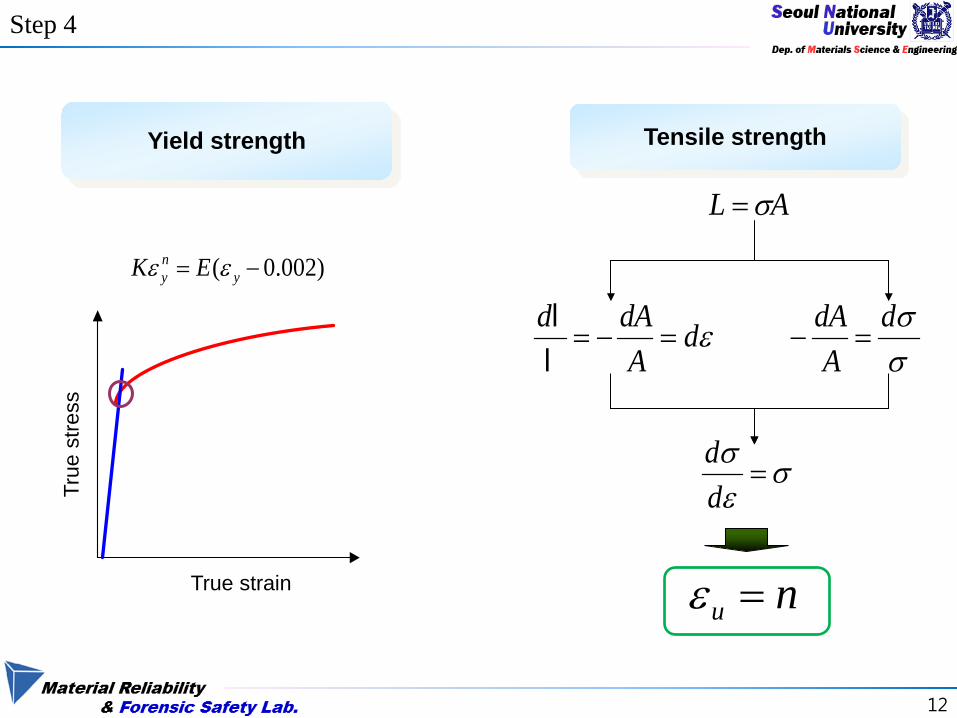
12
Step 4
)0020( minus= yny EK εε
True
stre
ss
True strain
Yield strength
AL σ=
εdA
dAd=minus=
ll
σσd
AdA
=minus
σεσ
=dd
Tensile strength
nu =ε
13
POSCO project
(Evaluation of dynamic tensile property)
14
background
Room Temperature Low Temperature
Strain rate range 0001s 1s 10s 100s 200s
Schematic diagram of strain rate regimes
Dynamic strain rage 100 ~ 104 s
15
Definition of strain rate
Representative stress-strain definition (Expanding Cavity Model)
RhRh
Ra 222020 minus
==ε21
caL
πψσ =
Representative Stress Representative Strain
indentation strain rate (Spherical indenter)
- Representative strain definition RhRh
Ra 222020 minus
==ε
- indentation strain rate dt
dεε =amp )( VRhfdt
d=
εhc depth R indenter radius
V indentation speed
16
Definition of strain rate
4 6 8 10 12 14 16 18 20 22 2404
05
06
07
08
09
10
11
stra
in ra
te [
s]
h [um]
Dynamic range (100 ~ )
rarr 압입 깊이 별 strain rate 감소
Change of strain rate
according to indentation depth
0 20 40 60 80 100 120 140 160
02
04
06
08
10
12
14 strain rate=constant strain rate=changed
V[m
mm
in]
Depth[um]
example Indentation strain rate = 001
17
Result
000 005 010 015 020 0250
100
200
300
400
500
600
700
Tensile_Static Tensile_01s Tensile_02s Tensile_1s Indentation_Static Indentation_001s Indentation_005s
True
stre
ss[M
Pa]
True strain
[S-S curve comparison]
Confirming tendency of s-s curve according to strain rate
18
Equipment improvement
Minute control
AIS3000 Hardware
0 1 2 3 4 5 6 7 8 9 1000
02
04
06
08
10
Inde
ntat
ion
stra
in ra
te [
s]
indentation speed [mmmin]
19
Dynamic hardening factor
σd f(εp) = σs f(εp) middot DHF
DHF Dynamic Hardening Factor
Experimental constant (D)
[Joon mo Choung Dynamic hardening behaviors of various marine structural steels
considering dependencies on strain rate and temperature 2013]
20
Change in DHF
1E-3 001 01 1 10
10
11
12
13 SM400 (σ0=2967MPa)
DHF
Strain Rate [s]1E-3 001 01 1 10
10
11
12
13 SM490 (σ0=3421MPa)
DHF
Strain Rate [s]
SM400 SM490
Change in DHF with strain rate (tensile test)
01 1
100
101
102
103
104
105
106
107 SM490 σ0 = 3213 MPa
DHF
Strain Rate [s]01 1
100
101
102
103
104
105
106
107 SM400 σ0= 2664MPa
DHF
Strain Rate [s]
SM400 SM490
Change in DHF with strain rate (IIT)
21
Yield properties of PE pipe
22
Introduction
Gas Water Sewage Chemicals
In Industrial In Metropolitan
bull Corrosion amp Chemical resistance
bull Long life amp Life cycle cost savings
bull Leak free joint
bull Light weight
bull Flexibiility
bull High ductility
bull Easy installation
bull Fatigue amp Seismic resistance
Advantages of PE
23
Indenter
Background
Issue (Application to PE)
R
d1
R
d2
θ1
θ2
d
Residual Indent(top view)
Ψ=σR
mP Ψ Constraint Factor (about 3)
γε sin250=T
Representation
True strain εΤ
True
stre
ss σ
Τ
σ=E(ε-0002) σ=Kεn
Representative stress-strain points
E
In order to Evaluate Strength of Polyethylene Definition of strain rate on IIT is essential It is difficult to definite strain rate using spherical indenter Because the contact area is consistently changing during indentation
24
Indenter
Approach
Using flat-ended cylindrical indenter instead of spherical indenter
Characteristics
Indenter shape
Sharp Spherical
(Conventional representation)
Flat-ended cylindrical
No self-similarity Not keeping resemblance
during indentation X O O
Fixed contact area constant contact area during
indentation X X O
Closeness to compression test X O
25
Definition of strain
0
50
100
150
200
250
300
350
0 20 40 60 80 100
load
(kg
f)
depth (um)
a=250um
a=500um
a=1000um
Load-depth curve
00
05
10
15
20
25
30
00 01 02 03 04Pm
(G
Pa)
hR
a=250um
a=500um
a=1000um
Load rArr Pm h rArr hR
Normalization
hR can be ldquoRepresentativerdquo strain
26
Strain rate
Rh
r
bullbull
minus=χ
ε 1
From flat-ended indentation for creep test
Rhqr 21
bullbull
sdot=εA
hqr
bullbull
sdot= 2ε
q1 amp q2 are constant
[PMSargent Mater Sci Technol 1992] [JLu J Mech Phys Solids 2003]
Experimental approach
In progresshellip
27
28
(Indentation strain rate definition by Doener amp Nix )
Indentation strain rate
Indentation test parameter
Plastic zone expansion rate of indentation

15
Definition of strain rate
Representative stress-strain definition (Expanding Cavity Model)
RhRh
Ra 222020 minus
==ε21
caL
πψσ =
Representative Stress Representative Strain
indentation strain rate (Spherical indenter)
- Representative strain definition RhRh
Ra 222020 minus
==ε
- indentation strain rate dt
dεε =amp )( VRhfdt
d=
εhc depth R indenter radius
V indentation speed
16
Definition of strain rate
4 6 8 10 12 14 16 18 20 22 2404
05
06
07
08
09
10
11
stra
in ra
te [
s]
h [um]
Dynamic range (100 ~ )
rarr 압입 깊이 별 strain rate 감소
Change of strain rate
according to indentation depth
0 20 40 60 80 100 120 140 160
02
04
06
08
10
12
14 strain rate=constant strain rate=changed
V[m
mm
in]
Depth[um]
example Indentation strain rate = 001
17
Result
000 005 010 015 020 0250
100
200
300
400
500
600
700
Tensile_Static Tensile_01s Tensile_02s Tensile_1s Indentation_Static Indentation_001s Indentation_005s
True
stre
ss[M
Pa]
True strain
[S-S curve comparison]
Confirming tendency of s-s curve according to strain rate
18
Equipment improvement
Minute control
AIS3000 Hardware
0 1 2 3 4 5 6 7 8 9 1000
02
04
06
08
10
Inde
ntat
ion
stra
in ra
te [
s]
indentation speed [mmmin]
19
Dynamic hardening factor
σd f(εp) = σs f(εp) middot DHF
DHF Dynamic Hardening Factor
Experimental constant (D)
[Joon mo Choung Dynamic hardening behaviors of various marine structural steels
considering dependencies on strain rate and temperature 2013]
20
Change in DHF
1E-3 001 01 1 10
10
11
12
13 SM400 (σ0=2967MPa)
DHF
Strain Rate [s]1E-3 001 01 1 10
10
11
12
13 SM490 (σ0=3421MPa)
DHF
Strain Rate [s]
SM400 SM490
Change in DHF with strain rate (tensile test)
01 1
100
101
102
103
104
105
106
107 SM490 σ0 = 3213 MPa
DHF
Strain Rate [s]01 1
100
101
102
103
104
105
106
107 SM400 σ0= 2664MPa
DHF
Strain Rate [s]
SM400 SM490
Change in DHF with strain rate (IIT)
21
Yield properties of PE pipe
22
Introduction
Gas Water Sewage Chemicals
In Industrial In Metropolitan
bull Corrosion amp Chemical resistance
bull Long life amp Life cycle cost savings
bull Leak free joint
bull Light weight
bull Flexibiility
bull High ductility
bull Easy installation
bull Fatigue amp Seismic resistance
Advantages of PE
23
Indenter
Background
Issue (Application to PE)
R
d1
R
d2
θ1
θ2
d
Residual Indent(top view)
Ψ=σR
mP Ψ Constraint Factor (about 3)
γε sin250=T
Representation
True strain εΤ
True
stre
ss σ
Τ
σ=E(ε-0002) σ=Kεn
Representative stress-strain points
E
In order to Evaluate Strength of Polyethylene Definition of strain rate on IIT is essential It is difficult to definite strain rate using spherical indenter Because the contact area is consistently changing during indentation
24
Indenter
Approach
Using flat-ended cylindrical indenter instead of spherical indenter
Characteristics
Indenter shape
Sharp Spherical
(Conventional representation)
Flat-ended cylindrical
No self-similarity Not keeping resemblance
during indentation X O O
Fixed contact area constant contact area during
indentation X X O
Closeness to compression test X O
25
Definition of strain
0
50
100
150
200
250
300
350
0 20 40 60 80 100
load
(kg
f)
depth (um)
a=250um
a=500um
a=1000um
Load-depth curve
00
05
10
15
20
25
30
00 01 02 03 04Pm
(G
Pa)
hR
a=250um
a=500um
a=1000um
Load rArr Pm h rArr hR
Normalization
hR can be ldquoRepresentativerdquo strain
26
Strain rate
Rh
r
bullbull
minus=χ
ε 1
From flat-ended indentation for creep test
Rhqr 21
bullbull
sdot=εA
hqr
bullbull
sdot= 2ε
q1 amp q2 are constant
[PMSargent Mater Sci Technol 1992] [JLu J Mech Phys Solids 2003]
Experimental approach
In progresshellip
27
28
(Indentation strain rate definition by Doener amp Nix )
Indentation strain rate
Indentation test parameter
Plastic zone expansion rate of indentation
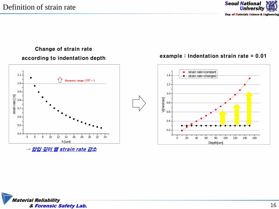

20
Change in DHF
1E-3 001 01 1 10
10
11
12
13 SM400 (σ0=2967MPa)
DHF
Strain Rate [s]1E-3 001 01 1 10
10
11
12
13 SM490 (σ0=3421MPa)
DHF
Strain Rate [s]
SM400 SM490
Change in DHF with strain rate (tensile test)
01 1
100
101
102
103
104
105
106
107 SM490 σ0 = 3213 MPa
DHF
Strain Rate [s]01 1
100
101
102
103
104
105
106
107 SM400 σ0= 2664MPa
DHF
Strain Rate [s]
SM400 SM490
Change in DHF with strain rate (IIT)
21
Yield properties of PE pipe
22
Introduction
Gas Water Sewage Chemicals
In Industrial In Metropolitan
bull Corrosion amp Chemical resistance
bull Long life amp Life cycle cost savings
bull Leak free joint
bull Light weight
bull Flexibiility
bull High ductility
bull Easy installation
bull Fatigue amp Seismic resistance
Advantages of PE
23
Indenter
Background
Issue (Application to PE)
R
d1
R
d2
θ1
θ2
d
Residual Indent(top view)
Ψ=σR
mP Ψ Constraint Factor (about 3)
γε sin250=T
Representation
True strain εΤ
True
stre
ss σ
Τ
σ=E(ε-0002) σ=Kεn
Representative stress-strain points
E
In order to Evaluate Strength of Polyethylene Definition of strain rate on IIT is essential It is difficult to definite strain rate using spherical indenter Because the contact area is consistently changing during indentation
24
Indenter
Approach
Using flat-ended cylindrical indenter instead of spherical indenter
Characteristics
Indenter shape
Sharp Spherical
(Conventional representation)
Flat-ended cylindrical
No self-similarity Not keeping resemblance
during indentation X O O
Fixed contact area constant contact area during
indentation X X O
Closeness to compression test X O
25
Definition of strain
0
50
100
150
200
250
300
350
0 20 40 60 80 100
load
(kg
f)
depth (um)
a=250um
a=500um
a=1000um
Load-depth curve
00
05
10
15
20
25
30
00 01 02 03 04Pm
(G
Pa)
hR
a=250um
a=500um
a=1000um
Load rArr Pm h rArr hR
Normalization
hR can be ldquoRepresentativerdquo strain
26
Strain rate
Rh
r
bullbull
minus=χ
ε 1
From flat-ended indentation for creep test
Rhqr 21
bullbull
sdot=εA
hqr
bullbull
sdot= 2ε
q1 amp q2 are constant
[PMSargent Mater Sci Technol 1992] [JLu J Mech Phys Solids 2003]
Experimental approach
In progresshellip
27
28
(Indentation strain rate definition by Doener amp Nix )
Indentation strain rate
Indentation test parameter
Plastic zone expansion rate of indentation
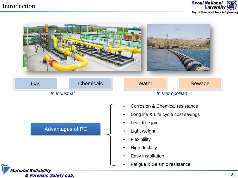

25
Definition of strain
0
50
100
150
200
250
300
350
0 20 40 60 80 100
load
(kg
f)
depth (um)
a=250um
a=500um
a=1000um
Load-depth curve
00
05
10
15
20
25
30
00 01 02 03 04Pm
(G
Pa)
hR
a=250um
a=500um
a=1000um
Load rArr Pm h rArr hR
Normalization
hR can be ldquoRepresentativerdquo strain
26
Strain rate
Rh
r
bullbull
minus=χ
ε 1
From flat-ended indentation for creep test
Rhqr 21
bullbull
sdot=εA
hqr
bullbull
sdot= 2ε
q1 amp q2 are constant
[PMSargent Mater Sci Technol 1992] [JLu J Mech Phys Solids 2003]
Experimental approach
In progresshellip
27
28
(Indentation strain rate definition by Doener amp Nix )
Indentation strain rate
Indentation test parameter
Plastic zone expansion rate of indentation

27
28
(Indentation strain rate definition by Doener amp Nix )
Indentation strain rate
Indentation test parameter
Plastic zone expansion rate of indentation

28
(Indentation strain rate definition by Doener amp Nix )
Indentation strain rate
Indentation test parameter
Plastic zone expansion rate of indentation
![Statistica descrittiva con R - Laboratorio di Statistica ... · voti_sorted >=75 #vettore di TRUE e FALSE ## [1] TRUE TRUE TRUE TRUE TRUE TRUE TRUE TRUE TRUE TRUE TRUE ## [12]](https://img.pdfslide.tips/doc/110x75/5fa7220773f533798518ec4c/statistica-descrittiva-con-r-laboratorio-di-statistica-votisorted-75.jpg)