Embed Size (px)
Citation preview

PIETRO PERSICO
Responsabile Progettazione e Laboratorio Prove Magnaghi Aeronautica e Salver
«BUILD TO PRINT» TO «BUILD TO SPEC»
EVOLUZIONE DI UN’AZIENDA AERONAUTICA
DA COSTRUIRE A DISEGNO A COSTRUIRE A SPECIFICA

Build to Print (B2P)
Definizione
“Build to Print” è il processo attraverso il quale un’azienda (fornitore o «supplier»)
realizza componenti, equipaggiamenti o sistemi, in accordo alle specifiche tecniche
dettate dal proprio committente (cliente o «customer») che specifica i requisiti
funzionali, realizza i disegni di dettaglio e d’assieme, decide le metodologie di
produzione e realizza i cicli di lavoro e le istruzioni di montaggio che saranno
utilizzati dal fornitore per produrre quanto richiesto nel documento “SoW”
(Statement of Work).

Build to Print (B2P)
L’approccio “Build to Print”
� Consente al «Customer» di mantenere il controllo della Proprietà Intellettuale, del know-how
e dei brevetti associati (“IPR”) e quindi di avere l’abilità di selezionare il miglior «Supplier»
per il prodotto
� Necessita di un’accurata fase di selezione del fornitore da parte del «Customer» e di continue
verifica delle capacità produttive del «Supplier» attraverso periodici “AUDITS”
� Richiede maggior lavoro e costi di sviluppo per il «customer» che rimane responsabile del
progetto e delle eventuali problematiche di qualità ad esso collegate
Un’azienda “Supplier” strutturata per la realizzazione del prodotto attraverso il processo “Build
to Print”, sviluppando adeguate competenze e capacità, ha come naturale prospettiva
l’evoluzione verso la connotazione di “Supplier” Build-to-Spec

Build to Spec (B2S)
Definizione
Il processo "Build-to-Spec“ si configura quando un’azienda (committente o «customer»)
seleziona un fornitore o «supplier» per realizzare un componente, un assieme, o un
sistema sulla base di specifici requisiti dimensionali, funzionali e prestazionali.
Con la Specifica Tecnica del “customer” e lo SoW vengono definiti i vincoli di progetto
ed i relativi gradi di libertà, ma in ultima analisi il «Supplier» è libero di utilizzare le
proprie “competenze“ ed il proprio “know-how” per progettare ed produrre quanto
commissionato.
Nel processo «Build to Spec» il «Supplier» realizza i disegni di dettaglio e d’assieme,
decide le metodologie di produzione e realizza i cicli di lavoro e le istruzioni di
montaggio in base all’esperienza ed alle proprie competenze per soddisfare i requisiti
della Specifica Tecnica secondo l’approccio di lavoro definito nel documento “SoW”
(Statement of work)

Con l’approccio “Build to Spec”
� Il fornitore «Supplier» detiene la piena responsabilità dell’intero progetto incluso
qualità, affidabilità e conformità ai requisiti definiti nella Specifica Tecnica.
� I disegni produttivi, le relazioni tecniche di dimensionamento e i parametri di
processo sono di proprietà del «Supplier» che esercita il diritto della Proprietà
Intellettuale «IPR», sgravando il cliente della “onere” di mantenere in casa
competenze che non costituiscono il “core business” dell’azienda.
Tale approccio ovviamente facilita l’integrazione verticalizzata nel “business” da
parte di “Suppliers” intraprendenti, ma soprattutto capaci e competenti
Build to Spec (B2S)

B2P (Build to Print) B2S (Build to Spec)
Costi Più alti per il cliente Più alti per il fornitore
Competenza/Expertise Cliente Fornitore
IPR Cliente Fornitore
Responsabilità del
ProgettoCliente Fornitore
Responsabilità
Qualifica/ CertificazioneCliente Fornitore
«BUILD TO PRINT» TO «BUILD TO SPEC»
Un’azienda seleziona un fornitore per un progetto “build-to-print” quando non ha le
competenze e le specializzazioni disponibili per il prodotto che intende realizzare, o quando
non dispone della capacità (risorse, spazi etc.) o delle attrezzature necessarie allo scopo.
Un progetto “build-to-spec” viene commissionato dal «Customer» per prodotti che non
costituiscono le competenze distintive e il “core business” identificative della propria azienda.
(i.e. Produttore di Aerei commissiona parti - strutturali e non- e/o equipaggiamenti/sistemi)

L’evoluzione di Magnaghi & Salver
…da “build-to-print” a “build-to-spec”

Magnaghi Aeronautica S.p.A.
Salver S.p.A. Metal Sud S.r.l. Magnaghi Aircraft S.r.l.Magnaghi Friuli
Aerospacial Ltda
Aeronautical Sector
Magnaghi Aeronautica Group

The group manages long-term relationships with top customers
worldwide (major OEMs in fixed and rotary wing sectors)

Magnaghi and Salver positioning
Aeronautical Sector Industry Structure Value Chain
• The aerospace manufacturing industry is generally divided into four
sub-components segments, with integration expertise of sub-
components remaining at Prime Contractor level
• Magnaghi refers to the Equipment segment, while Salver is fully
focused on composite-based aero-stuctures
• The industry value chain comprises three levels beneath the Prime
Contractor/Integrator (the OEM) with increasing value-add activity
(and complexity) further up the chain
• Over the last decade, through the development of increasingly
sophisticated capabilities (including design), accreditations and
approvals, Salver has sought to move up the value chain into higher
value-add activities typical of the Tier 1 supplier
Salver Magnaghi
Tier 3
Tier 2
Tier 1
� C27J
� KC390
� AW169
� P180
� AW129
� ATR 42/72
� SJ100
� M346
� ATR 42/72
� AW139
� C-Series
� P180
� B787
� B767/777
� A320
� CF34
Avionics
Engines
Aerostructures
PRIME
CONTRACTORS
Es: Boeing, Airbus,
Bombardier, Embraer,
Agusta, Piaggio, ecc.
Equipment
Magnaghi
Salver
Positioning of Magnaghi & Salver

Business Overview
Main
Activities
Key
Programs
& Customers
Production
Plants &
Staff
� Military: EFA, AMX, C27J, G222, A129,
NH90, M346, KC390
� Commercial: ATR 42/72, AW169, C Series,
SJ100, P180 Avanti III
� Design, development, qualification, and
production of Landing Gear and
Actuation Systems, hydraulic and
mechanical components
� Offered portfolio includes MRO services
Magnaghi Aeronautica S.p.A.
� ~28,000 sqm Naples site
� ~300 employees
�Military: C27J
�Business Jets: Falcon 2000, P180
�Civil: C Series, Boeing (incl. B787), Airbus
(incl. A380), AW 139
�Design, development, qualification, and
production of composite material
components and structures
Salver S.p.A.
� ~50,000 sqm Brindisi site
� ~290 employees

Magnaghi positioning (selected programs)
Magnaghi is generally positioned in the Value Chain as Tier 1/ Tier 2 supplier, developing and manufacturing complete
landing gear systems and complex components
IRIS-T
NLG/MLG
C27J ATR 42/72
NLG/MLG
KC390
CDAS
Stab Strut
EFA
Up Locks
and other
equipment
AW169
LG System LG
Components
M346
Motor Case
Tier 1
Tier 2
SJ100
LG
Components
Prime Contractor
Products
Programs
Salver positioning (selected programs)
Nacelle
components
Nacelle
components
Boeing
B787
Airbus
A320
Belly
fairings
Airbus
A380
Composite
Parts
Agusta Westland
AW139
Piaggio
P180
Multiple
components
ATR
42/72
Fan
cowls
GE
CF34
Radome
and panels
Multiple
components
Bombardier
C-Series
Multiple
components
Boeing
B767/777
Prime Contractor
Products
Programs
Tier 1
Tier 2
Tier 3
Salver is tipically positioned as a Tier 1/ Tier 2 supplier on the ongoing contracts

Intellectual property programs portfolio
Program Technical Description
Alenia Aermacchi C27J
Landing Gear
Actuation system
Steering system
Agusta Westland AW169Landing Gear
Electro-Mechanical Actuation System
NH Industries NH90Deck lock actuator
Deck lock hydraulic unit
Piaggio Aerospace P180Landing Gear
Actuation System
Alenia Aermacchi M346 LG Actuation system
Alenia Aermacchi Sky x
Landing Gear
Electro-Mechanical Actuation System
Steering System
Embraer KC 390Cargo Doors & Ramp Actuation System
Stabilizer Strut System
Agusta Westland AW 129 Landing Gear
Agusta Westland AW 109 Landing Gear
ATR 72 Tail Bumper
Bombardier C Series Wing Structural Components
Thanks to highly-skilled engineering dept, Magnaghi Group claims numerous intellectual property programs
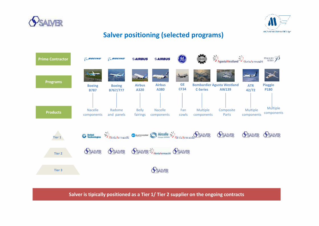
Magnaghi Production Evolution
Build to SpecificationCooperation
Bu
ild to
Prin
t
First m
ilitary
pa
rtne
rship
s
First civ
il pa
rtne
rship
s
First
Bu
ild to
Sp
ecifica
tion
sup
ply
con
tract
First m
ilitary
Bu
ild to
Sp
ecifica
tion
con
tract
First civ
ilB
uild
to S
pe
cificatio
n
con
tract
Build to Print
manufacturer
(Fiat G55)
1936 ‘60/’70 ‘80 2004 2012/132000
BTS contract for
AW169/P180/KC390
landing gear & Act SysBTS contract
for Sky X
landing gear
Build to Spec.
for the supply
of C27J
landing gearDetail design
for A109 and
ATR
Partnership
with Messier
Bugatti*
(G222)
Build to Print
*= today Messier-Dowty
� Design, analysis, test and
qualifications for landing gear
and Actuation Systems
Development & design
Manufacturing� Production of all landing gear
and actuation sys components
� Final tests and quality controls
Assembly� Landing gear “top assy"
e "sub assy" assembly
MRO� Assistance and MRO landing
systems

Magnaghi Facilities and production process
• Product Life Cycle
� Magnaghi is able to follow the entire process from concept to in-service maintainance
Raw material storage
RAW Material cutting and
deliveryRough machine Heat treatment Fine machining
Dimensional adn NDT
inspection
Special processes
Honings / Bushings Inst.
Paintings Assembly Testing Delivery
In-house Make or Buy

Fixed Wings - Commercial
Program System
ATR
72/42
Main and Nose
Landing Gears
SJ-100Main Landing Gear
Components
Progetti Magnaghi Build-to-Print

Fixed Wings – Transport & Defence/Trainer
Program System
EFA R/E system components
AMX Nose Landing Gear
G-222Landing Gear System
Progetti Magnaghi Build-to-Print

Fixed Wings - Transport
Program System
C-27JLanding Gear System
Progetti Magnaghi Build-to-Spec

Rotary wings
Program System
T-129 Main and Nose landing Gears
AW-109 Main and Nose Landing Gears
NH-90 Deck Lock System
AW-169 Landing gear System
Progetti Magnaghi Build-to-Spec

Fixed Wings - Commercial
Program System
ATR
72/42Tail Bumper
P-180Nose and Main
Landing Gears
Progetti Magnaghi Build-to-Spec

Fixed Wings – Defence/Trainer
Program System
M-346 R/E System
Progetti Magnaghi Build-to-Spec

Salver Production Evolution
Build to SpecificationCooperationBuild to PrintDevelopment & design
Manufacturing
Assembly
� Design, analysis, test and
qualifications for structural parts
and final assemblies in composite
material
� R&D of new composite
technology
� Manufacturing of composite
parts (carbon fiber, aramid, glass
fibers, etc.)
� CNC machines for laminating,
drilling, cutting prepregs,
contouring using laser
instruments
� Design and Planning Tools and
Jigs
� Managing entire process
of assembling composite
complex structures
A 3
80
EC
S
B7
67
/77
7 ra
do
me
A3
20
A3
80
py
lon
Fa
iring
B 7
87
En
gin
e O
ute
r Ba
rrel
B 7
87
EC
S D
uctin
g
Bo
mb
ard
ier C
-se
ries F
lap
s & S
po
iler
Fu
ll Bu
ild to
Sp
ecifica
tion
2001 2002 2003 2006 2007 2009 2012/132008
BtP
1999
Direct contract
with Eurocopter
MRP and
purchasing
Secondary
Structure Parts
Design &
Qualification
Boeing
Certification
Direct
contract with
Goodrich
Tooling planning
for Goodrich
Management
U.S. Supplier
TIER 1 for
primary
structure parts
Dedicated plant
for Bombardier
C-Series
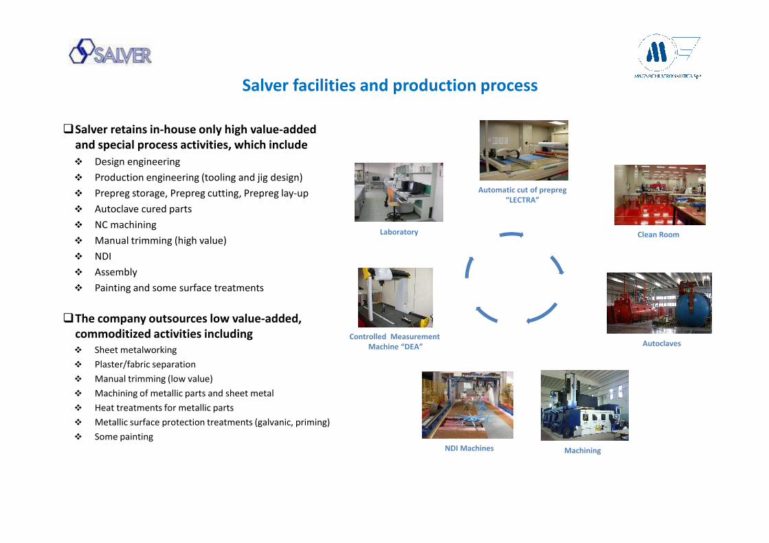
Salver facilities and production process
�Salver retains in-house only high value-added
and special process activities, which include
� Design engineering
� Production engineering (tooling and jig design)
� Prepreg storage, Prepreg cutting, Prepreg lay-up
� Autoclave cured parts
� NC machining
� Manual trimming (high value)
� NDI
� Assembly
� Painting and some surface treatments
�The company outsources low value-added,
commoditized activities including
� Sheet metalworking
� Plaster/fabric separation
� Manual trimming (low value)
� Machining of metallic parts and sheet metal
� Heat treatments for metallic parts
� Metallic surface protection treatments (galvanic, priming)
� Some painting
Clean RoomLaboratory
Controlled Measurement
Machine “DEA”
Automatic cut of prepreg
“LECTRA”
Autoclaves
NDI Machines Machining

B767 / B777 Radome Assy
Epoxy/Glass sandwich structure
A380 ECS – Composites
Ducts
Multinterface, Outlet, Oval
Ducts Made of hybrid
prepreg
B787 – Inlet Outer Barrel
CFRP laminate & sandwich
structure
B767
B777
A380
A380 ECS – Fan Cowls
B787 – ECS Ducts
B787
AW139 – Tail Plane
AW13
9
Kevlar laminate & sandwich
structure
Progetti Salver Build-to-Print
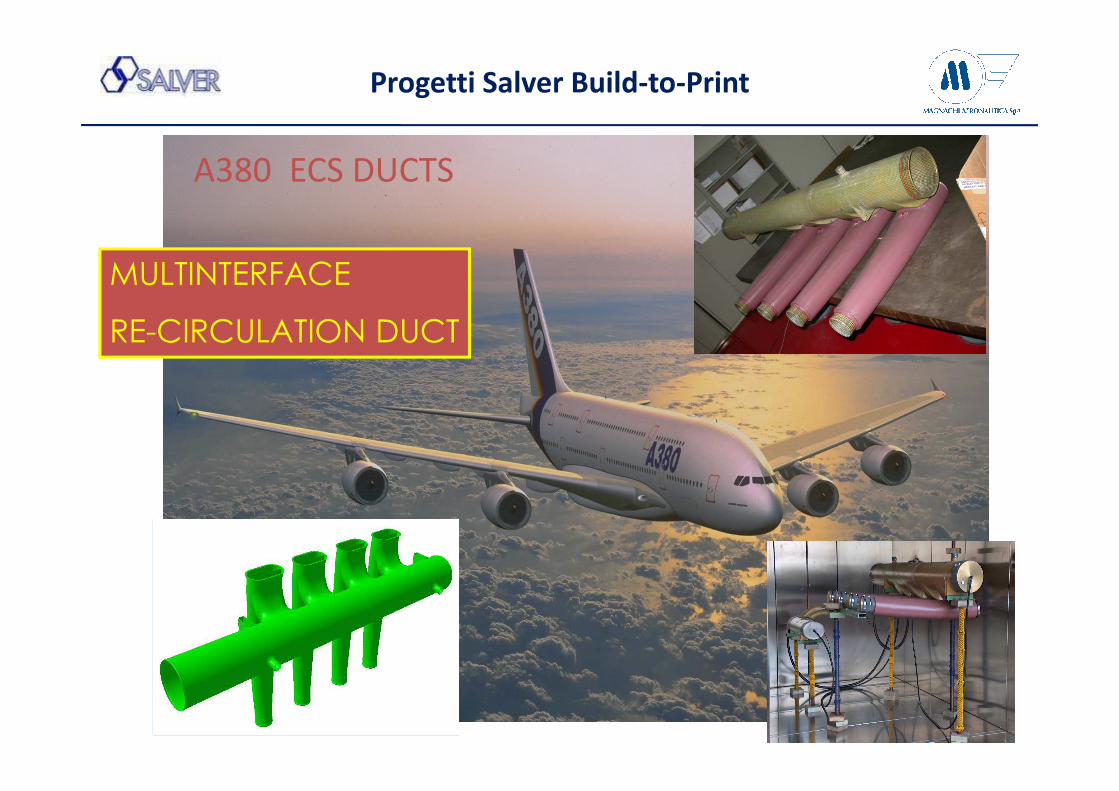
A380 ECS DUCTS
MULTINTERFACE
RE-CIRCULATION DUCT
Progetti Salver Build-to-Print

INVESCO
OUTLETS/DIFFUSERS
A380 ECS DUCTS
Progetti Salver Build-to-Print

Bombardier C-Series
• Bombardier’s new C-Series program consists of two models (C110 and C130) of a commercial, single-aisled regional aircraft designed to
carry between 100 and 150 passengers
• Once in operation, the C-Series is planned to have the lowest operating costs in its class
• Salver is a Tier 1, single source supplier to its customer Bombardier
• Assemblies supplied by Salver include
– Inboard and Outboard flaps
– Ground and Multi-Function spoilers
– Main landing gear bay doors
Salver’s first BtS program, with full responsibility for design, testing, certification and production
Salver Project Build-to-Spec

Primo volo prototipo sperimentale C-Series avvenuto a Montreal 16 Settembre 2013
La Certificazione per l’ntrata in servizio è attesa per Dicembre 2015
Outboard Flap
Inboard Flap
Salver Project Build-to-Spec
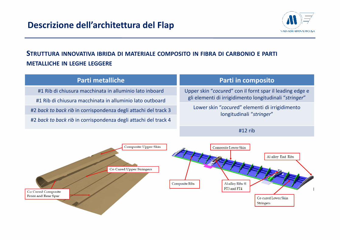
STRUTTURA INNOVATIVA IBRIDA DI MATERIALE COMPOSITO IN FIBRA DI CARBONIO E PARTI
METALLICHE IN LEGHE LEGGERE
Parti in composito
Upper skin “cocured” con il fornt spar il leading edge e
gli elementi di irrigidimento longitudinali “stringer”
Lower skin “cocured” elementi di irrigidimento
longitudinali “stringer”
#12 rib
Parti metalliche
#1 Rib di chiusura macchinata in alluminio lato inboard
#1 Rib di chiusura macchinata in alluminio lato outboard
#2 back to back rib in corrispondenza degli attachi del track 3
#2 back to back rib in corrispondenza degli attachi del track 4
Descrizione dell’architettura del Flap

Certifica delle
strutture in materiale
composito Part 1
•Il processo di certifica. Controllo e qualità del materiale prodotto
•Certificazione del prodotto.
•Test (Il Building-block approach (MIL-HDBK-17-1F)
Part 2
• La struttura della “Supply Chain”; Integrazione e logistica
Part 3
• L’evoluzione del Project management
Part 4
• Partener and Stakeholder
• Gestione del rischio. “Risk sharing”
…da “build-to-print” a “build-to-spec”
La fornitura:
“Extended Enterprise”
– Supply Chain System
Investimenti
Project Management

Ref. MIL-HDBK-17-3E
…Quality conformance tests are needed to assure the continued integrity of a characterized
material system. The tests performed must be able to characterize each batch/lot of material so
a proper assessment of critical properties of a material system can be made. These critical
properties provide information on the integrity of a material system with regard to material
properties, fabrication capability, and usage. Additionally, the test matrix must be designed to
economically and quickly evaluate a material system…”
Il controllo qualità in ambiente produttivo richiede l’ispezione ed il test del composito in ogni
fase dalla realizzazione del materiale fino alla produzione della parte specifica.
I test di ispezione devono essere effettuati separatamente per la resina, le fibre ed il laminato
(fabric o tape)
In particolare per il prepeg sono necessari test di ispezione in tutte le fasi: ricezione, messa in
opera e realizzaione della parte mediante test non distruttivi e distruttivi sia su parti campioni
che sul componente finito.
Materiali Compositi
Il processo di certificazione: Qualità e procedure

Ref. MIL-HDBK-17-3E
Process Certification: Quality ensure procedures
Materiali Compositi - Tipici test di ricezione/accettazione
Receiving inspection: l’utilizzatore del
material composito prepara le specifiche
dei controlli in accettazione del material
Per assicurare che incontri i requisiti
caratteristici definiti dal dipartimento di
Ingegneria
Process verification: L’ente Assicurazione
Qualità has la responsibilità di verificare che
I processi a cui è sottoposto il materiale
siano in linea con le specifiche definite dalla
Progettazione. Assicura quindi:
• Handling e conservazione del Materiale
• Idoneità delle attrezzature e degli
strumenti con cui si lavora
• La cura delle Parti
• Il Processo di Controllo dei campioni

Destructive tests: Spesso, quando non è possibile assicurare l’integrità strutturale del
material attraverso mezzi e metodi non distruttivi, sono necessarie prove distruttive.
Queste prove prevedono periodici sezionamenti a campione delle parti che hanno struttura
complessa.
Process Certification: Quality ensure procedures
The Composite Material

Process Certification

TRL 1
TRL 2
TRL 3
TRL 4
Conceptual Idea
Patent searches made, Conceptual schemes available, Manuf acturing concepts defined
Materials investigations started, Manufacturing concepts investig ated,
Preliminary Material available (new), Prelim Tooling available, Manuf acturing Trials started
Maturity Stages
TECHNOLOGY READINESS
TRL 5
TRL 6
TRL 7
TRL 8
TRL 9
Manufacturing Trials completed, Limited Material qualification data ava ilable (Coupons, T’s etc)
Product concepts frozen, Static & Fatigue testing underway, Material Allow able available, Prototypebuilt and tested in representative environment
Manufacturing Processes qualified, Production solutions (design & manufacturing ) qualified
Production Ready Technology , Requires Certification, Flight trialsunderway
Fully Productionised Technology, Flight Certified and fly ing with customer
APPLICATION READINESS
PRODUCTION READINESS
PPV
Start with Production
TECHNOLOGY READINESS LEVEL
Process Certification: Technologies Readiness plan

• Verify tooling performances, manufacturing process and method
• Validation and optimization of manufacturing phase
• Identification of manufacturing process parameter
Flat chargelamination
Charge hotforming
Stringer wet-assy
Cured “I” shapedStringer
Development manufacturing plan
Process Certification: Technologies Readiness plan

Process Certification: Technologies Readiness plan
MANUFACTURING DEMONSTRATOR

External vacuum Bag
MANUFACTURING DEMONSTRATOR
Internal vacuum Bag
Process Certification: Technologies Readiness plan

Lay-Up Tools Concept Flap
Process Certification: Technologies Readiness plan

Standard Invar Tools Example
Flaps Lay-Up Tools
Process Certification: Technologies Readiness plan

Demonstrator (Vacuum Bag)
3D Example Layup Tools Flap Lower Panel
In order to have a good compaction, 2 vacuum bag have been used.
The first one is inside the leading edge (so the plies of the leading edge will be compacted between the bag and the tool)
The second vacuum bag is the final bag that will cover all the tool. In this way, every part section is compacted between vacuum bag and rigid tool (tool skin or removable tools)
Double vacuum bag example
Tool side
Lay-Up Tools Concept Flap
Process Certification: Technologies Readiness plan

DEVELOPMENT OF CERTIFICATION AND VALIDATION TEST PR OGRAM
Testing Schedule & Cert Plan
L’obiettivo del Piano di Certificazione è definire I principi e le regole da seguire per ottenere laCertificazione della parte attreverso un accordo preliminare con le autorità certificanti coinvolte(FAA, EASA, etc.) definendo I “Means of Compliance” nella Qualification/Certification Matrix
Base di certificazione usata per qualificare il progetto C-Series:
• FAA - FAR Part 25 Amendment 25-1 fino a 25-114• EASA - Certification Specification 25, Initial Issue, Published 17 October 2003.• AC 20-107A or AMC No1 to CS 25.603
Product Certification: Test

Test Matrix example
Product Certification: Test
Test Category (sub-test)
Type Description Part Shape (Ref) QtyCon-
dition
Defect, Abuse & Impact Type &
Location
Loading - Column I
Loading - Column II
Test ObjectiveStrain gage
chn. QtyThickness (Ref)
Dimension (Ref.)TBC (mm)
Test Facility Site Magnaghi-Salver Activities
Full ScaleINBOARD FLAP Full
Scale TestsComplete assembled part 1 RT/AR
VID, BVID, Mfg defect
Static & CFRP DT
justification
saddles + hinges + actuators
To demonstrate load carrying capability of the inboard flap body under limit and ultimate static loads (including Environmental Knock Down
Factors) in retracted and deployed positions. To demonstrate the capability of composite structure for durability and damage tolerance.
To generate data to support validation of analysis.
16 axial, 4 rosette (TBC)
All 2330 x 678 N/AProvide the components for the Full Scale Test
Articles, Definition of impact locations, test article drawings, Test Setup Drawings (TBC).
Full ScaleINBOARD FLAP Full
Scale TestsComplete assembled part 1 RT/AR
VID, BVID, Mfg defect
Metal Parts Fatigue
saddles + hinges + actuators
To demonstrate durability and damage tolerance capability of inboard flap metallic internal parts and support structure. To generate data to
support validation of analysis.
16 axial, 4 rosette (TBC)
All 2330 x 678 N/AProvide the components for the Full Scale Test
Articles, Definition of impact locations, test article drawings, Test Setup Drawings (TBC).
Full ScaleINBOARD FLAP Full
Scale TestsComplete assembled part 1 RT/AR Mfg defect
Bird Strike Impact
To demonstrate bird strike capability of inboard flap and flap attachment structure mounted in a representative manner. To validate model of damage analysis prediction. To generate data to support validation of
residual strength analysis and demonstrate continue structural integrity post bird strike.
All 2330 x 678 N/AProvide the components for the Full Scale Test
Articles, Definition of impact locations, test article drawings, Test Setup Drawings (TBC).
Full ScaleOUTBOARD FLAP Full
Scale TestsComplete assembled part 1 RT/AR
VID, BVID, Mfg defect
Static & CFRP DT
justification
saddles + hinges + actuators
To demonstrate load carrying capability of the outboard flap body under limit and ultimate static loads (including Environmental Knock Down
Factors) in retracted and deployed positions. To demonstrate the capability of composite structure for durability and damage tolerance.
To generate data to support validation of analysis.
16 axial, 4 rosette (TBC)
All 4200 x 512 N/AProvide the components for the Full Scale Test
Articles, Definition of impact locations, test article drawings, Test Setup Drawings (TBC).
Full ScaleOUTBOARD FLAP Full
Scale TestsComplete assembled part 1 RT/AR
VID, BVID, Mfg defect
Metal Parts Fatigue
saddles + hinges + actuators
To demonstrate durability and damage tolerance capability of outboard flap metallic internal parts and support structure. To generate data to
support validation of analysis.
16 axial, 4 rosette (TBC)
All 4200 x 512 N/AProvide the components for the Full Scale Test
Articles, Definition of impact locations, test article drawings, Test Setup Drawings (TBC).
Sub-component
Box Skin Panel Skin + 3 spars flat panel 3 RT/AR BVID, Mfg defectStatic -
Compression1 Pristine + 2
Impacted
To validate the capability of the analysis method to predict the final strength of skin-Spar configuration under compressive loads and
evaluate the knockdown factor for damage and manufacturing defects on complex structure.
8 axial, 2 rosette, 4 EDI (TBC)
1 skin thickness TBDMagnaghi Aeronautica
Test Lab
Definition of impact locations, test article drawings, Test Setup Drawings. Tests Plan definition. Tests conduct. Test correlation
Sub-component
Box Skin Panel Skin + 3 spars flat panel 3 RT/AR BVID, Mfg defectStatic - Tension
1 Pristine + 2 Impacted
To validate the capability of the analysis method to predict the final strength of skin-spar configuration under tension loads and evaluate the
knockdown factor for damage and manufacturing defects on complex structure.
8 axial, 2 rosette, 4 EDI (TBC)
1 skin thickness TBDMagnaghi Aeronautica
Test Lab
Definition of impact locations, test article drawings, Test Setup Drawings. Tests Plan definition. Tests conduct. Test correlation
Sub-component
Box Skin Panel Skin + 3 spars flat panel 3 RT/AR BVID, Mfg defectFatigue
Compression3 Impacted
To validate the capability of the analysis method to predict the final strength of skin-spar configuration under fatigue compressive loads and
validate the Fatigue ELF obtained from coupon tests.
8 axial, 2 rosette, 4 EDI (TBC)
1 skin thickness TBDMagnaghi Aeronautica
Test Lab
Definition of impact locations, test article drawings, Test Setup Drawings. Tests Plan definition. Tests conduct. Test correlation
Sub-component
Box Skin Panel Skin + 3 spars flat panel 3 RT/AR BVID, Mfg defectFatigue - Tension
3 ImpactedTo validate the capability of the analysis method to predict the final
strength of skin-spar configuration under fatigue tension-compression loads and validate the Fatigue ELF obtained from coupon tests.
8 axial, 2 rosette, 4 EDI (TBC)
1 skin thickness TBDMagnaghi Aeronautica
Test Lab
Definition of impact locations, test article drawings, Test Setup Drawings. Tests Plan definition. Tests conduct. Test correlation
Sub-component
Box Skin Panel Flailing & Burst Tyre
Skin + 3 spars flat panel 1 RT/ARHigh Energy Impact (TBC)
ImpactTo evaluate the capability of inboard flap lower skin to resist to discrete
event damage caused from flailing tyre or tyre burst events.1 skin thickness TBD
Magnaghi Aeronautica Test Lab or External
Test Lab (TBD)
Definition of impact locations, test article drawings, Test Setup Drawings. Tests Plan definition. Tests conduct. Test correlation
Sub-component
Skin flat panel , Skin flat panel + hinges, Skin panel and
relative Al wedge, Skin flat panel + spar+ bolt
4 RT/ARLightning
StrikeDetermine the ability of skin panels and attached fittings to withstand
direct effect caused from a lightning striking to an aircraft.1 skin thickness TBD
Magnaghi Aeronautica Test Lab or External
Test Lab (TBD)
Definition of impact locations, test article drawings, Test Setup Drawings. Tests Plan definition. Tests conduct. Test correlation
Element Front Spar Double T-section beam 1+1 RT/AR BVID, Mfg defect Static1 for Impact test
survey+ 1 Bending load
To establish the impact energy to produce BVID in different location and to generate data to support validation of analysis. To demonstrate the
robustness of analysis method to predict failure
8 axial, 2 rosette, 4 EDI (TBC)
1 type TBDMagnaghi Aeronautica
Test Lab
Definition of impact locations, test article drawings, Test Setup Drawings. Tests Plan definition. Tests conduct. Test correlation
Element Middle/Rear Spar J-section beam 1+1 RT/AR BVID, Mfg defect Static1 for Impact test
survey+ 1 Bending load
To establish the impact energy to produce BVID in different location and to generate data to support validation of analysis. To demonstrate the
robustness of analysis method to predict failure
8 axial, 2 rosette, 4 EDI (TBC)
1 type TBDMagnaghi Aeronautica
Test Lab
Definition of impact locations, test article drawings, Test Setup Drawings. Tests Plan definition. Tests conduct. Test correlation
Element CFRP Rib Rib 1 RT/AR BVID, Mfg defect Static ShearTo evaluate the capability of composite ribs with several notch due to
mousehole to sustain shear loads and validate analysis method.8 axial, 2 rosette,
4 EDI (TBC)1 thickness type TBD
Magnaghi Aeronautica Test Lab
Definition of impact locations, test article drawings, Test Setup Drawings. Tests Plan definition. Tests conduct. Test correlation
CouponsUnnotched Tension Strenght & Modulus
coupon TBDRT+
CTD + HTW
N/A StaticDepends on test
methodMagnaghi Aeronautica
Lab (TBC)Data for Salver Material available from ASTM
Test methods
CouponsUnnotched Compression
Strenght & Moduluscoupon TBD
RT+ CTD + HTW
N/A StaticDepends on test
methodMagnaghi Aeronautica
Lab (TBC)Data for Salver Material available from ASTM
Test methods
Coupons ILSS coupon TBDRT+
CTD + HTW
N/A StaticDepends on test
methodMagnaghi Aeronautica
Lab (TBC)Data for Salver Material available from ASTM
Test methods
Coupons ILTS coupon TBDRT+
CTD + HTW
N/A StaticDepends on test
methodMagnaghi Aeronautica
Lab (TBC)Data for Salver Material available from ASTM
Test methods
Coupons Open Hole Compression coupon TBDRT+
CTD + HTW
N/A StaticDepends on test
methodMagnaghi Aeronautica
Lab (TBC)Data for Salver Material available from ASTM
Test methods
Coupons Filled Hole Compression coupon TBDRT+
CTD + HTW
N/A StaticDepends on test
methodMagnaghi Aeronautica
Lab (TBC)Data for Salver Material available from ASTM
Test methods
CouponsCompression After
Impactcoupon TBD
RT+ CTD + HTW
N/A StaticDepends on test
methodMagnaghi Aeronautica
Lab (TBC)Data for Salver Material available from ASTM
Test methods
Coupons Open Hole Tension coupon TBDRT+
CTD + HTW
N/A StaticDepends on test
methodMagnaghi Aeronautica
Lab (TBC)Data for Salver Material available from ASTM
Test methods
Coupons Filled Hole Tension coupon TBDRT+
CTD + HTW
N/A StaticDepends on test
methodMagnaghi Aeronautica
Lab (TBC)Data for Salver Material available from ASTM
Test methods
Coupons Bearing coupon TBDRT+
CTD + HTW
N/A StaticDepends on test
methodMagnaghi Aeronautica
Lab (TBC)Data for Salver Material available from ASTM
Test methods
Coupons Pull-trough coupon TBDRT+
CTD + HTW
N/A StaticDepends on test
methodMagnaghi Aeronautica
Lab (TBC)Data for Salver Material available from ASTM
Test methods
CouponsCompression After
Impactcoupon TBD
RT+ CTD + HTW
N/A FatigueDepends on test
methodMagnaghi Aeronautica
Lab (TBC)Data for Salver Material available from ASTM
Test methods
Coupons Open Hole Compression coupon TBDRT+
CTD + HTW
N/A FatigueDepends on test
methodMagnaghi Aeronautica
Lab (TBC)Data for Salver Material available from ASTM
Test methods
Test Article configuration Parameter of Tests
BVID to be specified from PAIManufacturing defect are simulated trhough teflon square 0.5" x 0.5" dimension

Building block approach
Functional area involved:
� Engineering: Analysis validation
� Laboratory: testing of full and subcomponent test article
�Production: manufacturing of test article
Hybrid CFRP+Metallic
Outboard Flap
Product Certification: Test

Test Strategy: “Building Block” approach
• Several coupon level tests that will characterize also the environmental effect
• Element and subcomponent tests are conducted at R.T. to establish point design values and validate analysis methods for panel, spars, ribs and joint.
• Full scale component tests, including static, fatigue, lightning and bird impact tests will be conducted to validate the design and analysis methods
Product Certification: Test

Coupons Test
Design allowable testing
• This testing is intended to cover any specific lay-ups with selected material system and confirm or update preliminary allowables used in the current phase.
• Layups tested are selected as representative of the designed structure, with the allowable generated at the critical environmental conditions.
Fastener validation testing
• This testing is intended to cover any specific fastener types or forms that do not exist within current database
Product Certification: Test

Coupons Test
Coupons have been tested for:
• Un-Notched Compression
• Open Hole Compression
• Compression After Impact
• Un-Notched Tension
• Filled Hole Tension
• Tension After Impact
• Bolted Joints (bearing and pull through)
• Laminate Inter-laminar Shear
• Laminate Inter-laminar Tension
• Compression After Impact Fatigue
• Open Hole Compression Fatigue
Product Certification: Test
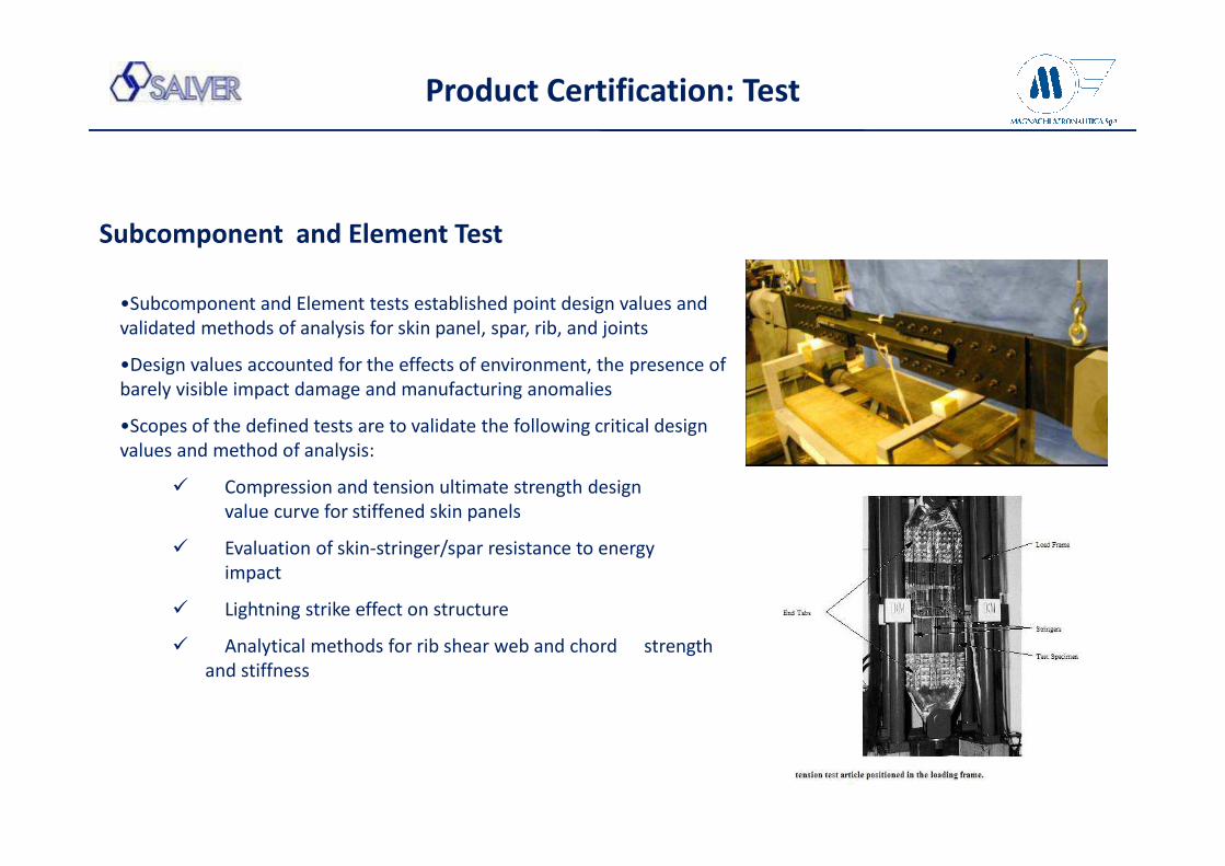
Subcomponent and Element Test
•Subcomponent and Element tests established point design values and
validated methods of analysis for skin panel, spar, rib, and joints
•Design values accounted for the effects of environment, the presence of
barely visible impact damage and manufacturing anomalies
•Scopes of the defined tests are to validate the following critical design
values and method of analysis:
� Compression and tension ultimate strength design
value curve for stiffened skin panels
� Evaluation of skin-stringer/spar resistance to energy
impact
� Lightning strike effect on structure
� Analytical methods for rib shear web and chord strength
and stiffness
Product Certification: Test

Product Certification: Test
Full Scale Test – Outboard Flap

Product Certification: Test
Full Scale Test – Inboard Flap

Product Certification: Test
Full Scale Test – Ground Spoiler

Full Scale Test: Bird Impact
• Complete Full Scale TA and attachment mounted in a realistically
representative manner on Bird Strike Test Rig
• Test performed at R.T.
• Selected areas of TA has been impacted by 8lb bird
• The data collected on test about damaged area and type has been
used to validate analysis method of damage prediction
Product Certification: Test

Bird Impact Lab Test
54
Bird Impact test

Fixture and scenario of a bird-strike
test.
a – air cannon bore;
b – velocity measure device;
c – test article;
d – high speed camera;
e – test bed;
f - safeguard screen;
g – load cell.
Bird Impact Test: sistema di acquisizione immagini/video ad alta velocità e risoluzione
55
Bird Impact test

C-Series Bird Impact Test
56
Bird Impact test: Video

CERTIFICATION AND VALIDATION TEST PROGRAM
Full Scale Test: Lightning Strike
• Test TA capabilities to resist through the thickness perforation
due to a lightning strike and capability to conduct current
through the structure.
• Test that lightning strike do not produce weld of fitting parts
• To generate data to support validation of analysis.
Product Certification

Supply Chain Structure, Logistic Integration evolution

“Project management is the application of knowledge, skills, tools, and techniques to project
activities to meet the project requirements. This application of knowledge requires the effective
management of the project management processes.” Ref. PM-BOK
Project management scope
• Select appropriate processes required to meet the project objectives;
• Use a defined approach that can be adapted to meet requirements;
• Establish and maintain appropriate communication and engagement with stakeholders;
• Comply with requirements to meet stakeholder needs and expectations; and
• Balance the competing constraints of scope, schedule, budget, quality, resources, and risk to
produce the specified product, service, or result.
Project Management

Evolution of Project Management

Evolution of Project Management
During project development all functional area need to be integrated based on TIME-COST-
QUALITY.

Investment PlanN°
Macchine/I
mpianti
increm.%
Autoclave 66,7%
Banco di lav.compositi/montaggio/sbavatura 2,5%
Cabina Verniciatura 36,4%
Carrello elevatore/Carroponte 6,5%
Centro di lavoro 10,8%
Clean room 50,0%
Compressore 21,4%
Foratrice 50,0%
Forno/Imp.Trattamenti termici 26,1%
Fresatrice 12,5%
Frigorifero/Refrigeratore/Congelatore 28,6%
Impianto CND 22,2%
Impianto galvanica 50,0%
Macchina di misura 20,0%
Macchina trazione/compressione provini 16,7%
Marcatrice/Stampigliatrice 20,0%
Nuova tecnologia Titanio 100,0%
Pallinatrice 40,0%
Pressa 17,5%
Rettificatrice 10,0%
Stampo termoregolato 100,0%
Tagliatrice/Troncatrice/Taglio al
plasma/waterjet 26,9%
Termoformatrice 40,0%
Tornio 8,5%
Trapano 3,3%
Gli investimenti rappresentano il vero punto di forza per
un’azienda nel significativo passaggio industriale da «Build to
Print» a «Build to Spec».
� Investire nelle risorse con specifiche competenze ed
esperienza
� Investire nell’acquisto di macchine e impianti per la
lavorazione del composito
� Potenziare le proprie capacità produttive con l’acquisto di
nuovi macchinari per le lavorazioni meccaniche per
incrementare la capacità o per soddisfare nuovi requisiti di
design che richiedono materiali innovativi come il titanio
� Introdurre/potenziare il settore dei processi speciali con
l’acquisizione di nuove tipologie di trattamenti
Investments

«BUILD TO PRINT» TO «BUILD TO SPEC»
CONCLUSIONI
Per un’azienda aeronautica il passaggio a «build to spec»
• rappresenta il momento della svolta industriale che stravolge l’impostazione e
l’organizzazione funzionale ed operativa dell’azienda con approccio «build to print».
• richiede investimenti non solo finanziari ma anche di competenze, esperienza e di numero
di risorse di gran lunga superiore a quello necessario per la gestione di un processo «build
to print»
• Costituisce il valore aggiunto per facilitare l’integrazione verticalizzata nel “business”

THE END
THANK YOU!