Embed Size (px)
Citation preview

8/6/2019 Explosion de Ducto
http://slidepdf.com/reader/full/explosion-de-ducto 1/4
Pipe Explosion During PiggingProcedure
n a hot summer day in Texas, whenthe temperature was 91ºF, contrac-tors were performing cleaning ser-vices in preparation for internally
coating a new section of 18-inch carbon steel pipeline. The pipeline was being constructed to carry brine to consumers from its sourceat a salt dome and had not yet been buried.That morning, three batches of methanol were pigged through the approximately 8,600 feetof pipe under service. As a final solvent rinse prior to application of the coating, 750 gallonsof methyl ethyl ketone (MEK) were loaded into the pipe in front of a solid urethane pig.
After removing the collected liquid MEK
from between the pig and the receiver gatevalve, operators opened the valve and bled some air from the receiver to allow the pig toenter. At that time, operators at the pig receiver reported hearing a loud “bang” and observinga shift in the position of the pipe, promptingthem to take cover.
Later inspection revealed that the pipelinehad ruptured at a fabricated bend located
approximately 90 feet from the pig receiver. Atthat time, no smoke or flames were observed and the line was completely depressurized.Figures 1 and 2 show the ruptured sectionof pipe as found after the incident. Soot wasdiscovered inside the pig receiver and the pigwas found pushed up against the receiver door.Luckily, the rupture occurred away from theworkstations and no injuries occurred.
Internal Coating ProcedureAt the time of the incident, a process was
under way to internally coat the new brine pipeline section with a protective epoxy mate-rial to inhibit corrosion. For this installation,
the process involved several steps: cleaning byabrasive blasting, solvent rinsing, and coating.
The blasting procedure begins with theinstallation of a blasting head at the launchend of the pipe. Abrasive material is injected into a high-velocity gas stream and removed from the opposite end of the pipe. The blastingmaterial used for this procedure was abrasiveflint and compressed nitrogen was used to blowit through the pipe. Following inspection, the blasting heads are removed and a pig launcher and receiver are installed on the pipeline.
Foam swab pigs are then run to removeresidual abrasive from the pipeline. After swabbing, several batches of methanol and afinal batch of MEK are run through the line toremove residual blasting dust. The run sheetsshow that the contractors ran three dry pigsand three batches of methanol on the previ-ous day, and three methanol batches and oneMEK batch on the day of the accident. Dry,compressed air was used to drive the pigs dur-ing these runs.
Normally, the solvent runs would be fol-lowed by a dry air purge, and then the finalepoxy coating would be performed.
Combustion In Pipes. Flames generally prop-agate much faster in confined volumes, such as
pipes, than in unconfined open spaces. Due tothe confinement, the heat and pressure gener-ated by the flame build up, and the confinementof this energy has a significant effect on the propagation of the flame. As a flame propagatesdown a long pipe, it encounters unburned gasesat increasing temperature and pressure, leadingto increased reaction rate and flame speed. Theresult of confinement is that the flame veloci-ties, temperatures, and pressures generated aremuch higher than those observed for flames inunconfined environments.
Deflagration To Detonation Transformation.A flame initially moves at a relatively slowvelocity, a phenomenon called “deflagration.”
The acceleration of a flame in a confined spacemay cause the flame front to accelerate tosupersonic speed. This is termed a deflagrationto detonation transformation (DDT). The com- pression waves ahead of the flame front col-lapse into a shock wave. Detonation incidentsinvolving flammable gases in the chemicalindustry frequently involve DDT.1 Turbulenceinduced by, for example, wall friction, obstruc-tions, and pipe bends can cause a deflagrationflame front to accelerate to detonation.
Continued propagation of the wave downthe pipe following the DDT leads to “overdriv-en detonation.” This is a transient state wherethe detonation wave overshoots its steadystate velocity. The peak pressure observed atthe location of an overdriven detonation can be 130 times greater than the pre-ignition pressure.2 If there is enough fuel in whichto propagate (and the pipe is still intact), theoverdriven wave decays to a steady detona-tion. If the pipe fails, the detonation wave mayquench due to the rapid expansion associ-ated with flow out of the break.3 If quenchingoccurs due to pipe rupture, this may mitigatethe hazards of the detonation wave propagat-ing farther into a piping system filled withcombustible gases.
By Lawrence M. Matta, Ph.D., P.E., C.F.E.I. and Gregory J. Haussmann,Ph.D., P.E., C.F.E.I., Exponent Failure Analysis, Inc., Houston, TX
Figure 1: View of ruptured pipeline sectionlooking toward pig receiver.
82 Pipeline & Gas Journal / September 08 / www.pgjonline.com
Figure 2: View of rupture onpig receiver side of the break.
8/6/2019 Explosion de Ducto
http://slidepdf.com/reader/full/explosion-de-ducto 2/484 Pipeline & Gas Journal / October 2008 / www.pgjonline.com
The distance from ignition to the formationof a steady detonation wave is known as the“run-up distance.” It has been reported that alength-to-diameter ratio of 10-60 is required for DDT to occur, depending on the sensitiv-ity of the reactant gas mixture. Exceptionallyreactive, unstable fuels, such as acetylene and ethylene, can run up to detonation in as littleas three diameters. The phenomenon of DDTis not well understood, and it is impossible to
accurately predict the location at which DDTwill occur for any specific combination of geometries and chemistries.
The run-up distance tends to decrease as pressure increases and as the mixture tendstoward stoichiometric. Research indicates thatrun-up distance is proportional to pipe diam-eter, and so for a certain gas mixture at aspecified initial pressure, transition to detona-tion occurs at a constant length-to-diameter ratio.1 The presence of pipe bends tends todecrease the run-up distance and toward DDT.The 18-inch pipeline involved in this incidentruptured approximately 90 feet from the pigreceiver — corresponding to 60 diameters. Thisis more than adequate distance for run up tooccur, even under less than ideal conditions.
MEK PropertiesMethyl ethyl ketone (MEK), also known as
2-butanone, is an organic solvent. It is typical-ly encountered as a low boiling point, rapidlyevaporating, colorless liquid that is partiallymiscible with water. Its general solvent prop-erties make it useful as a cleaning agent. Itsrapid evaporation rate make is especially use-
ful as a solvent in paintsand coatings.
With a flash point of 25°F and a boiling pointof 176°F, MEK is clas-sified as a Class IBFlammable Liquid. MEK is extremely flammable,and flames, sparks, elec-
trostatic discharge, heatand other ignition sourcesshould be avoided whenworking with it.4 The National Institute for Occupational Safety and Health (NIOSH) describesmixtures of MEK vaporsand air as explosive, and states, “Do NOT use compressed air for fill-ing, discharging, or handling.”5 The reported values of the lower explosion limit (LEL) and the upper explosion limit (UEL) are 1.8% and 11.5%, respectively.6
The saturation concentration of MEK in a
container can be determined from the vapor pressure. For example, at 68°F, the vapor pres-sure of MEK is roughly 1.4 PSI. Air saturated with MEK at atmospheric pressure (0 PSIG or 14.7 PSIA) has a vapor concentration of 1.4PSI / 14.7 PSI, or about 9.5%. An increase intemperature results in an increased vapor pres-sure and a corresponding rise in concentration.The pressure of the air, however, does notaffect the vapor pressure of MEK, so increas-ing the pressure of the air in the pipe at a fixed
temperature reduces the molar concentrationof MEK in the container.
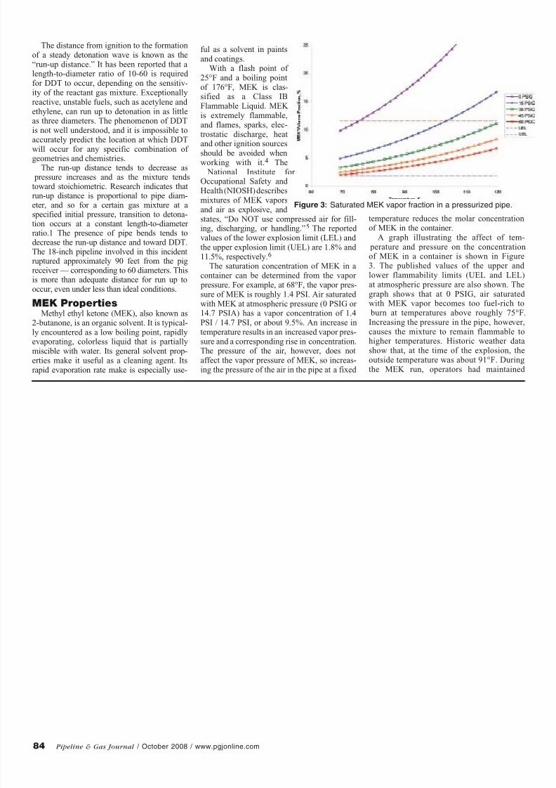
A graph illustrating the affect of tem- perature and pressure on the concentrationof MEK in a container is shown in Figure3. The published values of the upper and
lower flammability limits (UEL and LEL)at atmospheric pressure are also shown. Thegraph shows that at 0 PSIG, air saturated with MEK vapor becomes too fuel-rich to burn at temperatures above roughly 75°F.Increasing the pressure in the pipe, however,causes the mixture to remain flammable tohigher temperatures. Historic weather datashow that, at the time of the explosion, theoutside temperature was about 91°F. Duringthe MEK run, operators had maintained
Figure 3: Saturated MEK vapor fraction in a pressurized pipe.
8/6/2019 Explosion de Ducto
http://slidepdf.com/reader/full/explosion-de-ducto 3/4 Pipeline & Gas Journal / October 2008 / www.pgjonline.com 85
approximately 55 PSIG driving pressure and 30 PSIG backpressure on the pig.
Pipe Damage ByDetonations
Failure of a pipe subjected to detonationis significantly different than pipe failuredue to static overpressure. The highly local-ized, transient pressure peak associated witha detonation wave results in distinctive crack
propagation patterns.When a pipe ruptures due to a uniform
overpressure, the pipe fails under hoop stress.Propagation of the crack proceeds axiallyalong the pipe away from the initiation point,typically resulting in a classic “fish mouth”failure. This straight running crack occurs because the wall stress is approximately uni-form along the length of the pipe.
When a pipe fails under detonation loading,two cracks propagate away from the initiation point, one in the direction of the detonationwave propagation (forward) and one in theopposite direction (backward). Unlike failures
due to uniform loading, detonation-initiated cracks tend to travel straight for a short dis-tance and then either turn smoothly into a heli-cal crack or bifurcate into two branch cracksthat run sharply around the pipe, severing itwhen they meet on the opposite side.
Detonation pressure is localized and thewall stresses are not uniform along the lengthof the pipe. Bifurcation of the cracks favorsthe forward running crack. Chao and Shepard observed that bifurcation occurs on the for-
ward crack or both the forward and backward cracks, but not on the backward crack alone.3In other words, the pipe tends to separate com- pletely on the side of the rupture away from theignition point.
Incident PipeThe rupture occurred in a 45° pipe elbow.
The elbow was fabricated from seamlessA106B carbon steel 18-inch pipe with a
0.375-inch nominal wall thickness. The elbowwas formed with a 3-foot radius and a 5-footdrop-off on each side of the bend. The sec-tion of pipe had been hydrostatically tested in place at 1,500 PSIG for eight hours prior tothe explosion.
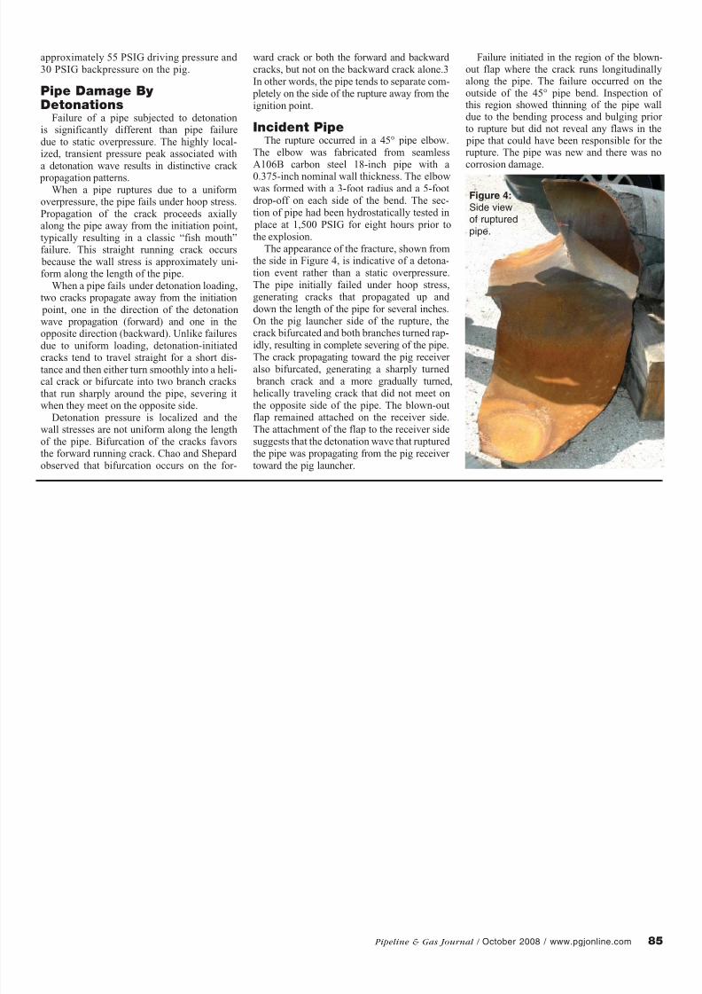
The appearance of the fracture, shown fromthe side in Figure 4, is indicative of a detona-tion event rather than a static overpressure.The pipe initially failed under hoop stress,generating cracks that propagated up and down the length of the pipe for several inches.On the pig launcher side of the rupture, thecrack bifurcated and both branches turned rap-
idly, resulting in complete severing of the pipe.The crack propagating toward the pig receiver also bifurcated, generating a sharply turned branch crack and a more gradually turned,helically traveling crack that did not meet onthe opposite side of the pipe. The blown-outflap remained attached on the receiver side.The attachment of the flap to the receiver sidesuggests that the detonation wave that ruptured the pipe was propagating from the pig receiver toward the pig launcher.
Failure initiated in the region of the blown-out flap where the crack runs longitudinallyalong the pipe. The failure occurred on theoutside of the 45° pipe bend. Inspection of this region showed thinning of the pipe walldue to the bending process and bulging prior to rupture but did not reveal any flaws in the pipe that could have been responsible for therupture. The pipe was new and there was nocorrosion damage.
Figure 4: Side viewof rupturedpipe.
8/6/2019 Explosion de Ducto
http://slidepdf.com/reader/full/explosion-de-ducto 4/486 Pipeline & Gas Journal / October 2008 / www.pgjonline.com
ConclusionsAn explosion occurred during a process to
internally coat a newly installed 18-inch pipe-line with a corrosion protecting epoxy coating.The explosion took place after a slug of MEK was pushed through the pipeline segmentusing a polyurethane pig driven by compressed air. The MEK left in the pipeline behind the pig mixed with the compressed air to form an
explosive mixture. The operators had removed the liquid MEK from between the pig and the pig trap, and were reportedly working to movethe pig into the receiver when they heard aloud noise and saw the pipe move.
Prior to the MEK run, the pipe had beensandblasted using a flint abrasive. Residualabrasive was pushed through the pipelineusing swab pigs. The swabbing procedureallows abrasive grit to enter the pig receiver.Possible ignition sources include sparking byflint abrasive scraped along the pipe or receiv-er wall by the pig and flint grit in a valve.
Upon ignition at the receiver end of the pipe,flame propagated through the pipeline toward the launcher. After passing through severalright angle turns and approximately 90 feet of pipe, the flame transitioned to a detonationas it entered the 45° elbow in which the rup-ture occurred. The pressure amplitude of theunsteady detonation wave exceeded the strengthof the pipe, resulting in localized wall failure.
The explosion and rupture of the pipecould have been prevented if an inert gas,
such as nitrogen, had been used to drive the pigs through the line and purge any remaining
volatiles following the run. Mixing flammable
liquids with air in a pipe certainly presents the possibility of producing an explosive mixture.
This particular incident occurred with MEK
but it could also have occurred with other flammable liquids. The accumulation of an
explosive mixture in a pipeline is unsafe and
one cannot rely on the absence of an ignitionsource during mechanical operations to pre-
vent a deflagration or detonation in the pipe.It is better to play it safe and use inert gas
when flammable liquids may be present in the
pipeline. P&GJ
Authors: Dr. Lawrence M. Matta is a Managing Engineer in Exponent’s Thermal
Sciences practice. He is registered in Texas as
a Professional Engineer and is a certified fireand explosion investigator (CFEI). Dr. Matta
specializes in combustion, thermodynamics,
heat transfer, and acoustics, and applies hisexpertise to the investigation of fires, explo-
sions, chemical releases, and combustionbased equipment. His fire investigation expe-rience includes commercial, residential and
industrial fires and explosions, ranging from
consumer products and small-engine equip-ment to pipelines and power plants. He has
a B.S. degree from Penn State and M.S. and
Ph.D. degrees in aerospace engineering fromGeorgia Tech.
Dr. Gregory J. Haussmann is a Principal Engineer and Exponent’s Houston Office Director. He is a registered professional mechanical engineer in California and Texasand is a certified fire and explosion investiga-tor (CFEI). He specializes in investigating thecause, origin, and propagation of fires and explosions. Dr. Haussmann has investigated several hundred fires and explosions includ-
ing refinery and chemical plant incidents;dust explosions; natural gas and propane fires and explosions; and residential, com-mercial, and industrial fires. He received his B.S. degree from Caltech and M.S. and Ph.D. degrees in mechanical engineering fromStanford University.R EFERENCES:
1 Helen James, “Detonations”, DIN TD5 039, British
Health and Safety Executive, Oct. 2001.
2 “Enardo – Flame Arrestor Technology”, http://www.
enardo.com/pdfs/tech_paper_fat.pdf.
3 T.W. Chao and J.E. Shepherd, “Fracture Response of
Externally Flawed Aluminum Cylindrical Shells Under
Internal Gaseous Detonation Loading”. International
Journal of Fracture, 134(1):59-90, July 2005.
4 Working Safely with Methyl Ethyl Ketone, http://
www.ccohs.ca/oshanswers/chemicals/chem_profiles/
mek/working_mek.html.
5 NIOSH International Chemical Safety Card 0179.
6 Shell Chemicals, Methyl Ethyl Ketone Data Sheet,
http://www.shellchemicals.com/chemicals/pdf/solvents/
chemical/ketones/mek_eu_26.pdf?section=our_prod-
ucts.