Embed Size (px)
Citation preview
BELL SYSTEM PRACTICES Plant Series
SECTION 081-740-105CA Issue B, October, 1972
Bell Canada Standard
EXTENSION LADDERS AND ATTACHMENTS
DESCRIPTION AND USE
CONTENTS PAGE
1. GENERAL . 73
2. DESCRIPTION OF STANDARD EXTENSION LADDER 73
3. SAFETY PRECAUTIONS 74
4. SELECTING LENGTH OF LADDER 75
5. SELECTING FOOTING 76
6. PROVISIONS FOR SUPPORTING UPPER END 77
7. RAISING AN•D LOWERING 84
8. HANDLING TOP SECTIONS 89
9. TRANSPORTING 91
10. INS·PECTION OF EXTENSION LADDERS 95
11. DEFECTS TO LOOK FOR ON LADDER RAILS 95
12. DEFECTS TO LOOK FOR ON LADDER RUNGS 96
13. D·EFECTS TO LOOK FOR ON LADDER FITTINGS 96
14. FIELD REPAIRS 98
15. STORAGE OF LADDERS 99
16. DISPOSITION OF DEFECTIVE LADDERS • 99
1. GENERAL
1.01 This section describes the standard Extension Ladder and standard attachments pre
sently used in Bell Canada and specifies methods of using the ladders and attachments safely.
1.02 This section is being issued to up-date the information and incorporate the Adden
dum Issue A which is hereby cancelled.
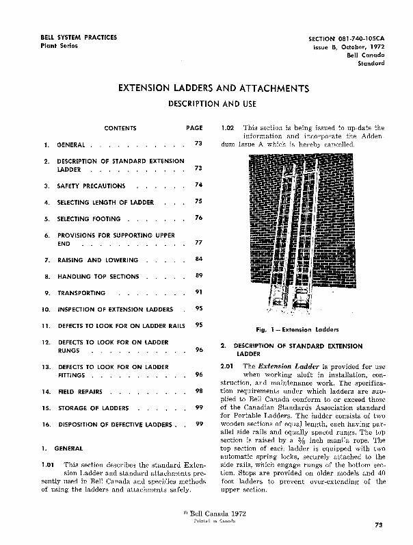
Fig. 1 - Extension Ladders
2. DESCRIPTION OF STANDARD EXTENSION LADDER
2.01 The Extension Ladder is provided for use when working aloft in installation, con
struction, and maintenance work. The specification requirements under which ladders are supplied to Bell Canada conform to or exceed those of the Canadian Standards Association standard for Portable Ladders. The ladder consists of two wooden sections of equal length, each having parallel side rails and equally spaced rungs. The top section is raised by a % inch manila rope. The top section of each ladder is equipped with two automatic spring locks, securely attached to the side rails, which engage rungs of the bottom section. Stops are provided on older models and 40 foot ladders to prevent over-extending of the upper section.
©Bell Canada 1972 Printed in Canada
73
SECTION 081-7 40-1 OSCA
2.02 Extension Ladders (Fig. 1) are supplied in 24, 28, 32 and 40 foot sizes. The size
of an Extension Ladder is the sum of the lengths of the two sections. All ladders are provided with spurs, unless otherwise specified, to prevent the ladder feet from slipping. 24 and 28 foot ladders are equipped with a Pole Grip unless ordered with Rotatable Ladder Hooks for aerial cable work.
3. SAFETY PRECAUTIONS
3.01 Whenever possible in areas exposed to vehicular traffic, place ladder on the strand
from the field side to avoid danger from passing vehicles.
3.02 If a ladder must be placed at a wc:rk location where it may be struck by vehicles or
pedestrians display warning flags or signs in the most advantageous locations.
3.03 Ensure that the ladder is in good working condition as defined in Part 10 of this sec-
tion.
3.04 Extension ladders are not to be left erect-ed overnight at work location, as this
creates a safety hazard to the public and especially to children. It is also contrary to the Canada Labour Code (Safety of Employees).
3.05 Before climbing, ensure that the rungs and side rails of the ladder, also the hands and
feet are free from any slippery substances.
3.06 Do not place ladders on boxes, barrels, or other objects to obtain additional height;
use a ladder of sufficient length for the job at hand.
3.07 Follow the instructions given in Para. 5.03 when the surface on which the base of the
ladder is resting is such that the ladder may have a tendency to slip.
3.08 Do not place a ladder inside or opposite an angle formed by wires or cables where
loosening of the wire or cable attachments might cause the ladder to move or fall.
74
3.09 Keep hands and feet off the rungs when raising or lowering the top section of an
extension ladder. Stand clear when the top section is being lowered so that it will not strike the feet.
Extreme caution must be exercised when lowering the upper section of a ladder equipped with the New Type Spring Lock (See Fig. 35). Always Lower The Upper Section Slowly.
3.10 Make certain that ladder locks are engaged properly and the ladder rope is tied secure
ly to one of the rungs of the bottom section before climbing an extension ladder.
3.11 If the ladder is equipped with ladder hooks and the ladder is to be used on aerial cable,
turn the hooks to the working position before the ladder is raised. Ladder hooks should be placed on the cable strand unless ladder is to be lashed as covered in Para. 6.05. Do not turn the hooks in before descending the ladder.
3.12 Place ladders not equipped with ladder hooks against the strand so that at least
two rungs extend above the strand when the craftsman is in position on the ladder.
3.13 Be especially careful when going up or down ladders during wet or icy weather.
3.14 Do not climb a ladder while wearing climbers.
3.15 Do not hurry when going up or down a ladder. Take one step at a time. Always
face the ladder when going up or down and be sure to have both hands free. Do not slide down an extension ladder.
3.16 Only one person at a time is permitted on a ladder.
3.17 When a ladder is lashed, secured or otherwise made stable so that it cannot fall, the
craftsman may improve his security by passing one leg between the rungs.
3.18 If the top end of the ladder is secured to suspension strand or other support, (See
Fig. 6 and 7) the craftsman may increase his safety by passing his safety strap around one
rung, or between two rungs and around one side rail.
3.19 When the ladder is properly placed on strand, (hooks over strand or two rungs
above strand) pass the safety strap around the strand and one side rail between two rungs.
3.20 The craftsman should always remember, to first make himself secure on the lad
der by passing his safety strap around one rung and the strand, or between two rungs, around the pole, and one side rail, so that he will not fall if he slips, loses his balance, or if something else goes wrong. Secure the ladder with a rope as shown in Figs. 6 and 7. The manner in which the craftsman secures himself to the ladder will depend on the nature of the work to be done.
3.21 Do not throw tools or materials to a crafts-man working on a ladder; raise them by
means of a handline. Be careful that tools or materials being used aloft cannot fall on persons passing below.
3.22 Do not attempt to lean to the side so far that the breast bone is beyond the side rail
when working on a ladder. Loss of footing in this position may cause loss of balance. The weight being shifted to one side of the ladder may cause it to twist and then slip at the top. Descend and move the ladder to the proper location.
3.23 When working from ladders do not allow drop wires, lashing wires, handlines, or
ladder ropes to dangle to the ground where they may be struck by passing vehicles. A wire or rope caught on a passing vehicle may pull the ladder causing it to fall or it may pull the craftsman off the ladder. The handline, when not in use, shall be tied to the lower portion of the ladder or pulled aloft.
3.24 Safety boots reaching above the ankle ( 6" or higher) should be worn when climbing
a ladder.
3.25 Never carry an extension ladder from one location to another while it is extended.
First lower the ladder and secure the ladder rope, then extend it again at the new location.
3.26 Point the spurs forward and downward, about 18" from the ground when carrying
a ladder on the shoulder.
ISS. B, SECTION 081-740-lOSCA
3.27 Avoid swinging the ladder into the path of passing vehicles or pedestrians when carry
ing a ladder or removing it from a vehicle.
3.28 Do not place ladders where they may come in contact with power lines.
3.29 Do not tie drop wires or pulling lines to ladders.
3.30 Do not use a ladder in a horizontal position as a platform, runway, or scaffold.
3.31 Do not place a ladder against a suspension strand which is held under tension by a
strand puller only.
3.32 Avoid placing a ladder in front of a door-way, especially where the door opens to
ward the ladder. Avoid placing a ladder near passageways, near moving machinery, or at locations where vehicles or pedestrians may strike or displace it. When these conditions cannot be avoided, or when a door cannot be secured in the open position or locked with no possibility of its being opened inadvertently, make arrangements to have the ladder guarded by another craftsman. Also, use warning devices to alert people of activity beyond a closed door.
4. SELECTING LENGTH OF LADDER
4.01 The maximum working length of an Extension Ladder is from 3 to 4 feet less than its
given size. The maximum working length for the various sizes of ladder is given in Table A.
TABLE A- WORKING LENGTHS OF EXTENSION LADDERS
SIZE OF MAXIMUM MINIMUM LADDER WORKING LENGTH o~~~'(;P FEET FEET)
20 17 3 24 21 3 28 25 3 32 29 3 36 32 4
40 36 4
The 20 and 36 ft. extension ladders are from returns only.
75
SECTION 081-740-105CA
4.02 Local conditions determine the size of lad-der to be carried by plant forces. However,
the 24 foot extension ladder will usually meet the conditions encountered by installation and repair forces and the 28- foot ladder will meet the requirements of the construction forces. The use of ladder hooks on 24 foot ladders will usually enable the service forces to perform their work along suspension strand without the need for carrying longer ladders. A ladder not equipped with ladder hooks may be used if two rungs extend beyond the strand when a man is standing on the ladder and it is secured to the strand as outlined in Paras. 6.01 through 6.07.
4.03 Always select a ladder of sufficient length for the work to be done. The length of
the ladder should be such that the work can be performed when standing no higher than on the fourth rung from the top, thus permitting the side rails to be grasped conveniently. If the ladder is too short for the work at hand, obtain a longer ladder.
5. SELECTING FOOTING
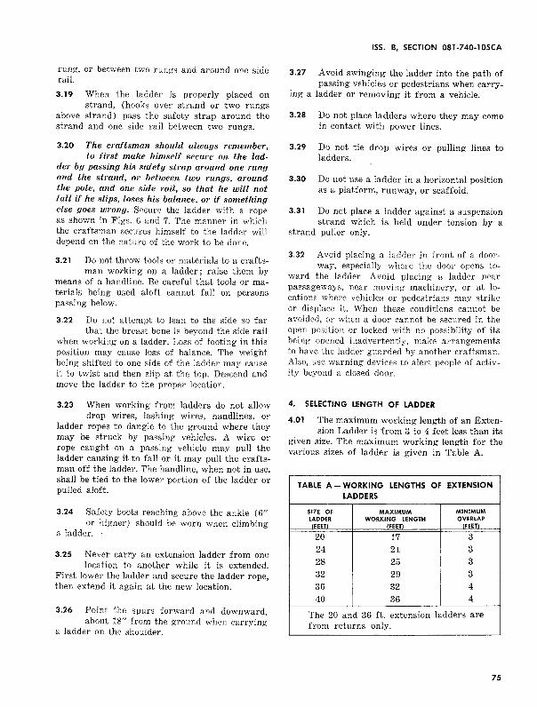
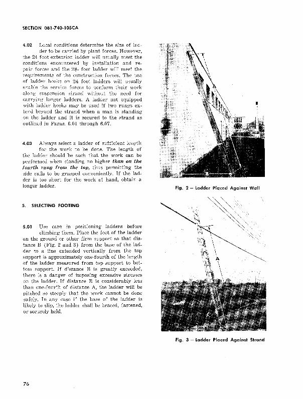
5.01 Use care in positioning ladders before climbing them. Place the foot of the ladder
on the ground or other firm support so that distance B (Fig. 2 and 3) from the base of the ladder to a line extended vertically from the top wpport is approximately one-fourth of the length of the ladder measured from top support to bottom support. If distance B is greatly exceeded, there is a danger of imposing excessive stresses on the ladder. If distance B is considerably less than one-fourth of distance A, the ladder will be pitched so steeply that the work cannot be done safely. In any case if the base of the ladder is likely to slip, the ladder shall be braced, fastened, or securely held.
76
Fig. 2- Ladder Plqced Ag<1inst W<1ll
Fig. 3 - L<1dder Pl<1ced Against Str<1nd
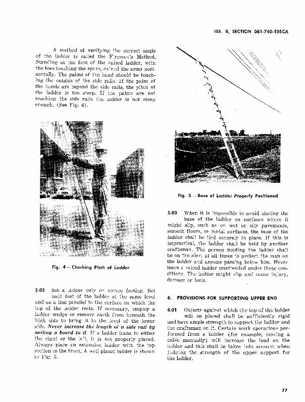
A method of verifying the correct angle of the ladder is called the Firemen's Method, Standing at the foot of the raised ladder, with the toes touching the spurs, extend the arms horizontally. The palms of the hand should be touching the outside of the side rails. If the palm of the hands are beyond the side rails, the pitch of the ladder is too steep. If the palms are not reaching the side rails the ladder is not steep enough. (See Fig. 4).
Fig. 4 - Checking Pitch of Ladder
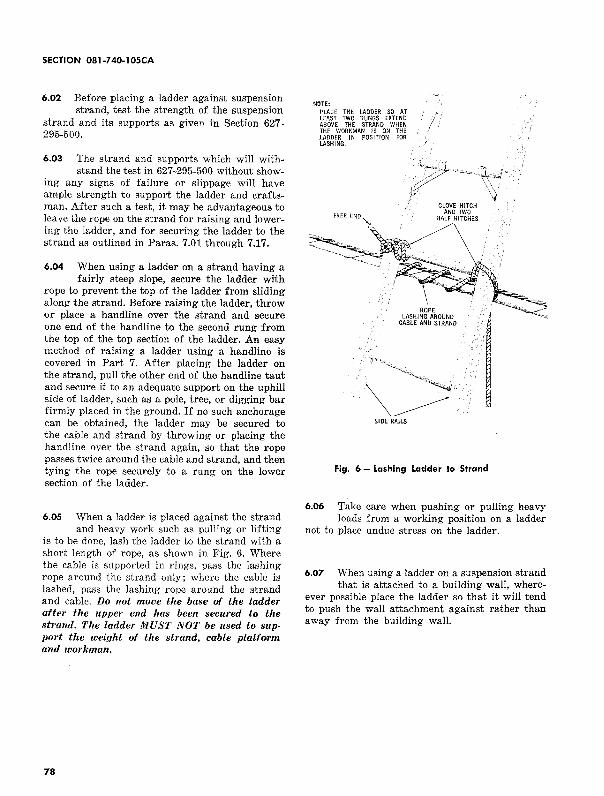
5.02 Set a ladder only on secure footing. Set both feet of the ladder at the same level
and on a line parallel to the surface on which the top of the ladder rests. If necessary, employ a ladder wedge or remove earth from beneath the high side to bring it to the level of the lower side. Never increase the length of a side rail by nailing a board to it. If a ladder leans to either the right or the left, it is not properly placed. Always place an extension ladder with the top section to the front. A well placed ladder is shown in Fig. 5.
ISS. B, SECTION 081-740-105CA
Fig. 5 - Base of Ladder Properly Positioned
5.03 When it is impossible to avoid placing the base of the ladder on surfaces where it
might slip, such as on wet or oily pavements, smooth floors, or metal surfaces, the base of the ladder shall be tied securely in place. If this is impractical, the ladder shall be held by another craftsman. The person holding the ladder shall be on the alert at all times to protect the man on the ladder and anyone passing below him. Never leave a raised ladder unattended under these conditions. The ladder might slip and cause injury, damage or both.
6. PROVISIONS FOR SUPPORTING UPPER END
6.01 Objects against which the top of the ladder will be placed shall be sufficiently rigid
and have ample strength to support the ladder and the craftsman on it. Certain work operations performed from a ladder (for example, moving a cable manually) will increase the load on the ladder and this shall be taken into account when judging the strength of the upper support for the ladder.
77
SECTION' 081-740-IOSCA
6.02 Before placing a ladder against suspension strand, test the strength of the suspension
strand and its supports as given in Section 627 · 295-500.
6.03 The strand and supports which will with-stand the test in 627-295-500 without show
ing any signs of failure or slippage will have ample strength to support the ladder and craftsman. After such a test, it may be advantageous to leave the rope on the strand for raising and lowering the ladder, and for securing the ladder to the strand as outlined in Paras. 7.01 through 7.17.
6.04 When using a ladder on a strand having a fairly steep slope, secure the ladder with
rope to prevent the top of the ladder from sliding along the strand. Before raising the ladder, throw or place a handline over the strand and secure one end of the handline to the second rung from the top of the top section of the ladder. An easy method of raising a ladder using a handline is covered in Part 7. After placing the ladder on the strand, pull the other end of the handline taut and secure it to an adequate support on the uphill side of ladder, such as a pole, tree, or digging bar firmly placed in the ground. If no such anchorage can be obtained, the ladder may be secured to the cable and strand by throwing or placing the handline over the strand again, so that the rope passes twice around the cable and strand, and then tying the rope securely to a rung on the lower section of the ladder.
6.05 When a ladder is placed against the strand and heavy work such as pulling or lifting
is to be done, lash the ladder to the strand with a short length of rope, as shown in Fig. 6. Where the cable is supported in rings, pass the lashing rope around the strand only; where the cable is lashed, pass the lashing rope around the strand and cable. Do not move the base of the ladder after the upper end has been secured to the strand. The ladder MUST NOT be used to support the weight of the strand, cable platform and workman.
78
NOTE' PLACE THE LADDER SO AT LEAST TWO RUNGS EXTEND ABOVE THE STRAND WHEN THE WORKMAN IS ON THE LADDER IN POSITION FOR lASHING.
FREE END\~
SIDE RAILS
CLOVE HITCH AND TWO
HALF HITCHES
/\
Fig. 6- Lashing Ladder to Strand
6.06 Take care when pushing or pulling heavy loads from a working position on a ladder
not to place undue stress on the ladder.
6.07 When using a ladder on a suspension strand that is attached to a building wall, where
ever possible place the ladder so that it will tend to push the wall attachment against rather than away from the building wall.
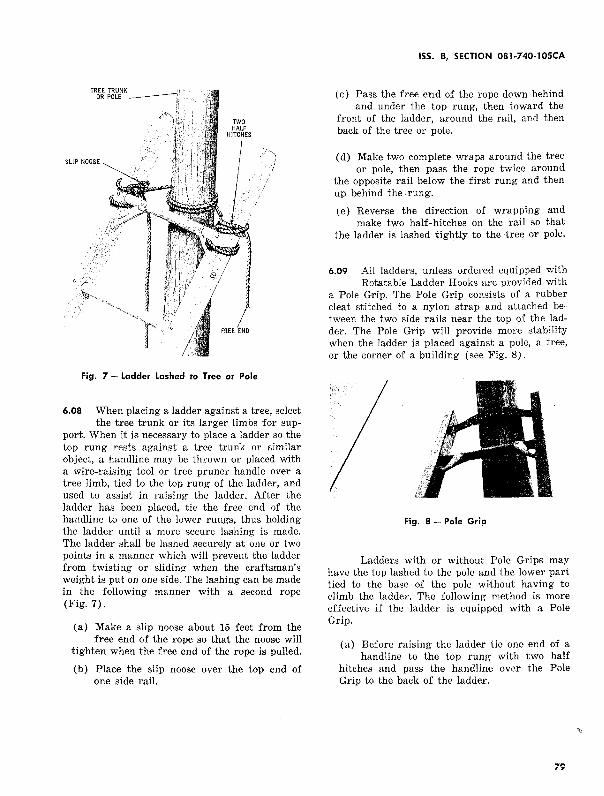
Fig. 7- Ladder Lashed to Tree or Pole
6.08 When placing a ladder against a tree, select the tree trunk or its larger limbs for sup
port. When it is necessary to place a ladder so the top rung rests against a tree trunk or similar object, a handline may be thrown or placed with a wire-raising tool or tree pruner handle over a tree limb, tied to the top rung of the ladder, and used to assist in raising the ladder. Mter the ladder has been placed, tie the free end of the handline to one of the lower rungs, thus holding the ladder until a more secure lashing is made. The ladder shall be lashed securely at one or two points in a manner which will prevent the ladder from twisting or sliding when the craftsman's weight is put on one side. The lashing can be made in the following manner with a second rope (Fig. 7).
(a) Make a slip noose about 15 feet from the free end of the rope so that the noose will
tighten when the free end of the rope is pulled.
(b) Place the slip noose over the top end of one side rail.
ISS. 8, SECTION 081-740-lOSCA
(c) Pass the free end of the rope down behind and under the top rung, then toward the
front of the ladder, around the rail, and then back of the tree -or pole.
(d) Make two complete wraps around the tree or pole, then pass the rope twice around
the opposite rail below the first rung and then up behind the rung.
(e) Reverse the direction of wrapping and make two half-hitches on the rail so that
the ladder is lashed tightly to the tree or pole.
6.09 All ladders, unless ordered equipped with Rotatable Ladder Hooks are provided with
a Pole Grip. The Pole Grip consists of a rubber cleat stitched to a nylon strap and attached between the two side rails near the top of the ladder. The Pole Grip will provide more stability when the ladder is placed against a pole, a tree, or the corner of a building (see Fig. 8).
Fig. 8 - Pole Grip
Ladders with or without Pole Grips may have the top lashed to the pole and the lower part tied to the base of the pole without having to climb the ladder. The following method is more effective if the ladder is equipped with a Pole Grip.
(a) Before raising the ladder tie one end of a handline to the top rung with two half
hitches and pass the handline over the Pole Grip to the back of the ladder.
79
SECTION 081-740-IOSCA
80
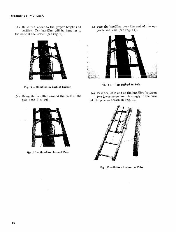
(b) Raise the ladder to the proper height and position. The handline will be hanging to
the back of the ladder (see Fig. 9).
Fig. 9- Handline in Back of Ladder
(c) Bring the handline around the back of the pole (see Fig. 10).
Fig. 10- Handline Around Pole
(d) Flip the handline over the end of the opposite side rail (see Fig. 11).
Fig. II - Top Lashed to Pole
(e) Pass the loose end of the handline between two lower rungs and tie snugly to the base
of the pole as shown in Fig. 12.
I Fig. 12 - Bottom Lashed to Pole
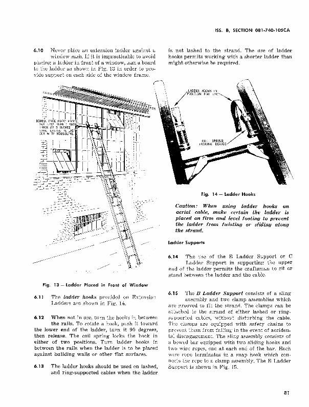
6.10 Never place an extension ladder against a window sash. If it is impracticable to avoid
placing a ladder in front of a window, lash a board to the ladder as shown in Fig. 13 in order to provide support on each side of the window frame.
Fig. 13 - Ladder Placed in Front of Window
6.11 The ladder hooks provided on Extension Ladders are shown in Fig. 14.
6.12 When not in use, turn the hooks in between the rails. To rotate a hook, push it toward
the lower end of the ladder, turn it 90 degrees, then release. The coil spring locks the hook in either of two positions. Turn ladder hooks in between the rails when the ladder is to be placed against building walls or other flat surfaces.
6.13 The ladder hooks should be used on lashed, and ring-supported cables when the ladder
ISS. B, SECTION 081-740-105CA
is not lashed to the strand. The use of ladder hooks permits working with a shorter ladder than might otherwise be required.
Fig. 14 - Ladder Haaks
Caution: When using ladder hooks on aerial cable, make certain the ladder is placed on firm and level footing to prevent the ladder from twisting or sliding along the strand.
Ladder Supports
6.14 The use of the B Ladder Support or C Ladder Support in supporting the upper
end of the ladder permits the craftsman to sit or stand between the ladder and the cable.
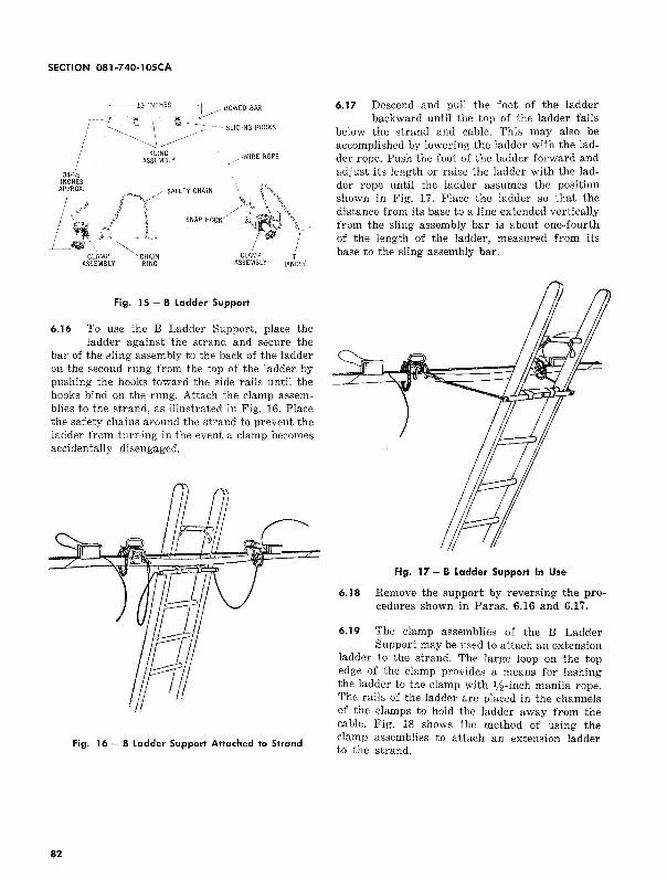
6.15 The B Ladder Support consists of a sling assembly and two clamp assemblies which
are grooved to fit the strand. The clamps can be attached to the strand of either lashed or ringsupported cables, without disturbing the cable. The clamps are equipped with safety chains to prevent them from falling in the event of accidental disengagement. The sling assembly consists of a bowed bar equipped with two sliding hooks and two wire ropes, one at each end of the bar. Each wire rope terminates in a snap hook which con .. nects the rope to a clamp assembly. The B Ladder Support is shown in Fig. 15.
81
SECTION 081-7 40-1 05CA
I '
;
34-112
r I
1----·19 INCHES I
r t:., \ t,-~~ . .
~~1.~/ SLING
ASSEMBLY
BOWED BAR
-·-SLIDING HOOKS
__..---WIRE ROPE
INCHES APPROX. ft"~ / SAFETY CHAIN 6-.::"\,
I t ,., / "". \ '\ i··. I\ / .. ,., I ~ {~~ J.. SNAP HOOK/ "'Ill~ ~\
L...i114Jii \ "" I CLAMP ""·CHAIN CLAMP T
ASSEMBLY RING ASSEMBLY HANDLE
Fig, 15- 8 ladder Support
6.16 To use the B Ladder Support, place the ladder against the strand and secure the
bar of the sling assembly to the back of the ladder on the second rung from the top of the ladder by pushing the hooks toward the side rails until the hooks bind on the rung. Attach the clamp assemblies to the strand, as illustrated in Fig. 16. Place the safety chains around the strand to prevent the ladder from turning in the event a clamp becomes accidentally disengaged,
Fig. 16 - 8 ladder Support Attached to Strand
82
6.17 Descend and pull the foot of the ladder backward until the top of the ladder falls
below the strand and cable. This may also be accomplished by lowering the ladder with the ladder rope. Push the foot of the ladder forward and adjust its length or raise the ladder with the ladder rope until the ladder assumes the position shown in Fig. 17. Place the ladder so that the distance from its base to a line extended vertically from the sling assembly bar is about one-fourth of the length of the ladder, measured from its base to the sling assembly bar.
Fig. 17- 8 Ladder Support In Use
6.18 Remove the support by reversing the procedures shown in Paras. 6.16 and 6.17.
6.19 The clamp assemblies of the B Ladder Support may be used to attach an extension
ladder to the strand. The large loop on the top edge of the clamp provides a means for lashing the ladder to the clamp with %-inch manila rope. The rails of the ladder are placed in the channels of the clamps to hold the ladder away from the cable. Fig. 18 shows the method of using the clamp assemblies to attach an extension ladder to the strand.
2 2
Fig. 18 - Ladder Attached to Strand with B. Ladder Support Clamps
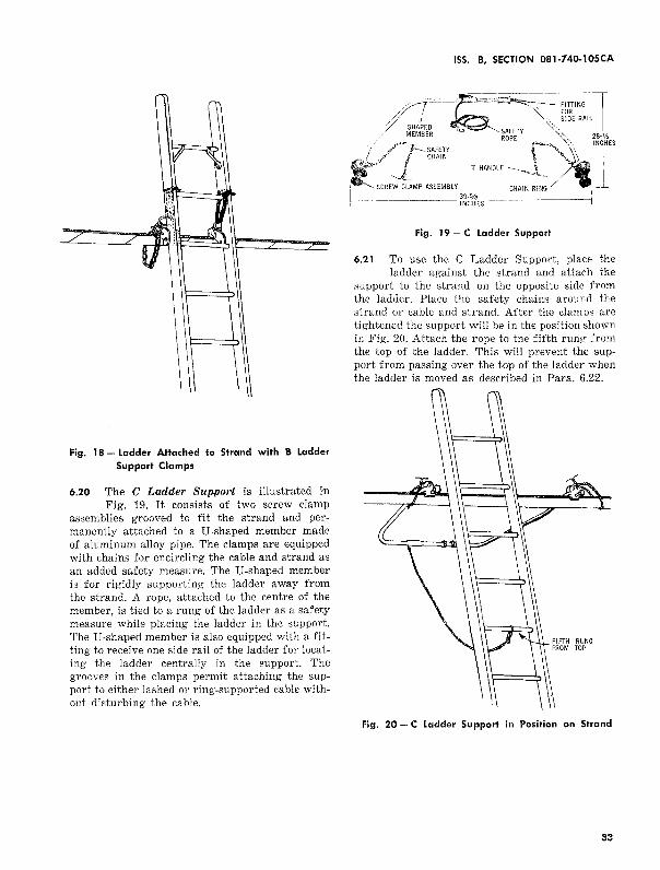
6.20 The C Ladder Support is illustrated in Fig. 19. It consists of two screw clamp
assemblies grooved to fit the strand and permanently attached to a U-shaped member made of aluminum alloy pipe. The clamps are equipped with chains for encircling the cable and strand as an added safety measure. The U-shaped member is for rigidly supporting the ladder away from the strand. A rope, attached to the centre of the member, is tied to a rung of the ladder as a safety measure while placing the ladder in the support. The U-shaped member is also equipped with a fitting to receive one side rail of the ladder for locating the ladder centrally in the support. The grooves in the clamps permit attaching the support to either lashed or ring-supported cable without disturbing the cable.
ISS. B, SECTION 081-740-105CA
Fig. 19 - C ladder Support
6.21 To use the C Ladder Support, place the ladder against the strand and attach the
support to the strand on the opposite side from the ladder. Place the safety chains around the strand or cable and strand. After the clamps are tightened the support will be in the position shown in Fig. 20. Attach the rope to the fifth rung from the top of the ladder. This will prevent the support from passing over the top of the ladder when the ladder is moved as described in Para. 6.22.
Fig. 20- C Ladder Support in Position on Strand
83
SECTION 081-740-lOSCA
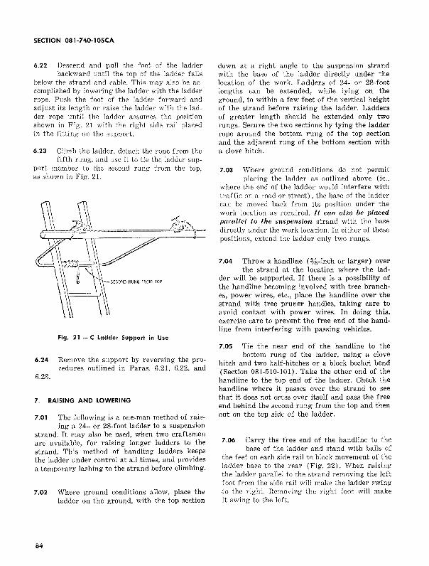
6.22 Descend and pull the foot of the ladder backward until the top of the ladder falls
below the strand and cable. This may also be accomplished by lowering the ladder with the ladder rope. Push the foot of the ladder forward and adjust its length or raise the ladder with the ladder rope until the ladder assumes the position shown in Fig. 21 with the right side rail placed in the fitting on the support.
6.23 Climb the ladder, detach the rope from the fifth rung, and use it to tie the ladder sup
port member to the second rung from the top, as shown in Fig. 21.
Fig. 21 - C Ladder Support in Use
6.24 Remove the support by reversing the procedures outlined in Paras. 6.21, 6.22, and
6.23.
7. RAISING AND LOWERING
7.01 The following is a one-man method of rais-ing a 24- or 28-foot ladder to a suspension
strand. It may also be used, when two craftsmen are available, for raising longer ladders to the strand. This method of handling ladders keeps the ladder under control at all times, and provides a temporary lashing to the strand before climbing.
7.02 Where ground conditions allow, place the ladder on the ground, with the top section
84
down at a right angle to the suspension strand with the base of the ladder directly under the location of the work. Ladders of 24- or 28-foot lengths can be extended, while lying on the ground, to within a few feet of the vertical height of the strand before raising the ladder. Ladders of greater length should be extended only two rungs. Secure the two sections by tying the ladder rope around the bottom rung of the top section and the adjacent rung of the bottom section with a clove hitch.
7.03 Where ground conditions do not permit placing the ladder as outlined above (ie.,
where the end of the ladder would interfere with traffic on a road or street) , the base of the ladder can be moved back from its position under the work location as required. It can alsfJ be placed parallel to the suspension strand with the base directly under the work location. In either of these positions, extend the ladder only two rungs.
7.04 Throw a handline (%-inch or larger) over the strand at the location where the lad
der will be supported. If there is a possibility of the handline becoming involved with tree branches, power wires, etc., place the handline over the strand with tree pruner handles, taking care to avoid contact with power wires. In doing this, exercise care to prevent the free end of the handline from interfering with passing vehicles.
7.05 Tie the near end of the handline to the bottom rung of the ladder, using a clove
hitch and two half-hitches or a block becket bend (Section 081-510-101). Take the other end of the handline to the top end of the ladder. Check the handline where it passes over the strand to see that it does not cross over itself and pass the free end behind the second rung from the top and then out on the top side of the ladder.
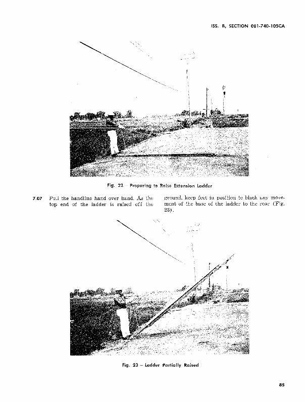
7.06 Carry the free end of the handline to the base of the ladder and stand with balls of
the feet on each side rail to block movement of the ladder base to the rear (Fig. 22). When raising the ladder parallel to the strand removing the left foot from the side rail will make the ladder swing to the right. Removing the right foot will make it swing to the left.
ISS. B, SECTION 081-740-lOSCA
f i
Fig. 22 - Preparing to Raise Extension Ladder
7.07 Pull the handline hand over hand. As the top end of the ladder is raised off the
ground, keep feet in position to block any movement of the base of the ladder to the rear (Fig. 23).
Fig. 23 - Ladder Partially Raised
85
SECTION 081-7 40-1 05CA
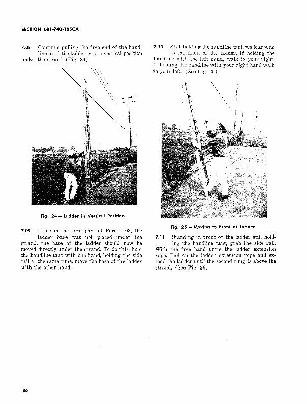
7.08 Continue pulling the free end of the handline until the ladder is in a vertical position
under the strand (Fig. 24).
Fig. 24- Ladder in Vertical Position
7.09 If, as in the first part of Para. 7.03, the ladder base was not placed under the
strand, the base of the ladder should now be moved directly under the strand. To do this, hold the handline taut with one hand, holding the side rail at the same time, move the base of the ladder with the other hand.
86
7.10 Still holding the handline taut, walk around to the front of the ladder. If holding the
handline with the left hand, walk to your right. If holding the handline with your right hand walk to your left. (See Fig. 25)
Fig. 25 - Moving to Front of Ladder
7.11 Standing in front of the ladder still hold-ing the handline taut, grab the side rail.
With the free hand untie the ladder extension rope. Pull on the ladder extension rope and extend the ladder until the second rung is above the strand. (See Fig. 26)
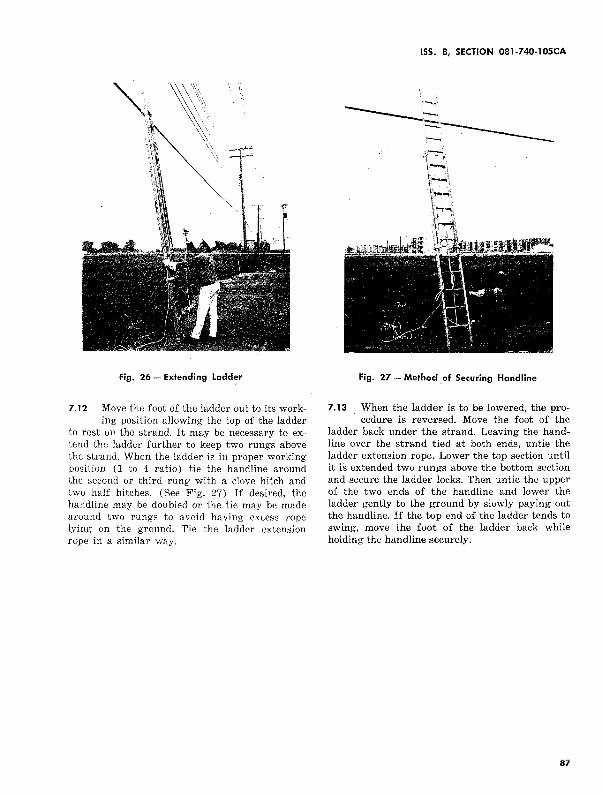
Fig. 26 _, Extending Ladder
7.12 Move the foot of the ladder out to its work-ing position allowing the top of the ladder
to rest on the strand. It may be necessary to extend the ladder further to keep two rungs above the strand. When the ladder is in proper working position (1 to 4 ratio) tie the handline around the second or third rung with a clove hitch and two half hitches. (See Fig. 27) If desired, the handline may be doubled or the tie may be made around two rungs to avoid having excess rope lying on the ground. Tie the ladder extension rope in a similar way.
ISS. B, SECTION 081-740-lOSCA
Fig. 27- Method of Securing Handline
7.13 When the ladder is to be lowered, the pro-cedure is reversed. Move the foot of the
ladder back under the strand. Leaving the handline over the strand tied at both ends, untie the ladder extension rope. Lower the top section until it is extended two rungs above the bottom section and secure the ladder locks. Then untie the upper of the two ends of the handline and lower the ladder gently to the ground by slowly paying out the handline. If the top end of the ladder tends to swing, move the foot of the ladder back while holding the handline securely.
87
SECTION 081-740-IOSCA
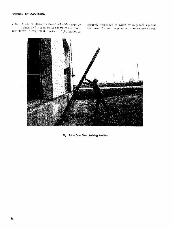
7.14 A 24-, or 28-foot Extension Ladder may be raised or lowered by one man in the man
ner shown in Fig. 28 if the foot of the ladder is
securely embedded in earth or is placed against the base of a wall, a pole, or other secure object.
Fig. 28- One Man Raising Ladder
88
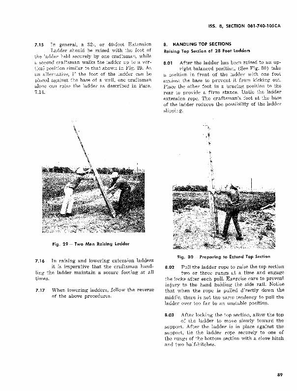
7.15 In general, a 32-, or 40-foot Extension Ladder should be raised with the foot of
the ladder held securely by one craftsman, while a second craftsman walks the ladder up to a vertical position similar to that shown in Fig. 29. As an alternative, if the foot of the ladder can be placed against the base of a wall, one craftsman alone can raise the ladder as described in Para. 7.14.
Fig. 29- Two Men Raising Ladder
7.16 In raising and lowering extension ladders it is imperative that the craftsman hand
ling the ladder maintain a secure footing at all times.
7.17 When lowering ladders, follow the reverse of the above procedures.
ISS. B, SECTION 081-740-lOSCA
8. HANDLING TOP SECTIONS
Raising Top Section of 28 Foot Ladders
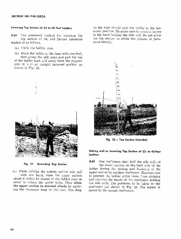
8.01 After the ladder has been raised to an up-right balanced position, (See Fig. 30) take
a position in front of the ladder with one foot against the base to prevent it from kicking out. Place the other foot in a bracing position to the rear to provide a firm stance. Untie the ladder extension rope. The craftsman's foot at the base of the ladder reduces the possibility of the ladder slipping.
Fig. 30- Preparing to Extend Top Section
8.02 Pull the ladder rope to raise the top section two or three rungs at a time and engage
the locks after each pull. Exercise care to prevent injury to the hand holding the side rail. Notice that when the rope is pulled directly down the
middle, there is not the same tendency to pull the ladder over too far to an unstable position.
8.03 After locking the top section, allow the top of the ladder to move slowly toward the
support. After the ladder is in place against the support, tie the ladder rope securely to one of the rungs of the bottom section with a clove hitch and two half-hitches.
89
SECTION 081-740-IOSCA
lowering Top Section of 24 to 28 Foot Ladders
8.04 The prefernd method for lowering the top section of 24, and 28-foot extension
ladders is as follows.
(a) Untie the ladder rope.
(b) Block the ladder at the base with one foot, then grasp the side rails and pull the top
of the ladder back and away from the support until it is in an upright balanc.ed position as shown in Fig. 31.
Fig. 31 -Extending Top Section
(c) While holding the bottom section side rail with one hand, raise the upper section
about 6 inches by means of the ladder rope in order to release the ladder locks. Then allow the upper section to descend slowly by applying the necessary drag on the rope. The drag
90
on the rope should hold the ladder in the balanced position. Exercise care to prevent injury to the hand holding the side rail. Do not allow the top section to strike the ground or pavement sharply.
Fig. 32 - Top Section Extended
Raising and/ or Lowering Top Section of 32- to 40-Foot ladders
8.05 One craftsman shall hold the side rails of the lower section on the back side of the
ladder during the raising and lowering of the upper section by another craftsman. Exercise care to prevent the ladder guide irons from striking and injuring the hands of the craftsman holding the side rails. The positions to be taken by the craftsmen are shown in Fig. 33. The ladder is raised by the second craftsman.
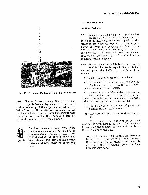
Fig. 33 -Two-Man Method of Extending Top Section
8.06 The craftsman holding the ladder shall keep his feet and legs clear of the side rails
and bottom rung of the upper section while it is being lowered. The craftsman lowering the top
section shall check its downward movement with the ladder rope so that the top section does not
strike the ground or pavement sharply.
Ladders equipped with New Type Spring Lock shall not be lowered by free fall. The mechanism of these locks cannot operate at such a speed and may catch a lower rung of the bottom section and thus crack or break this rung.
ISS. B, SECTION 081-740-105CA
9. TRANSPORTING
On Motor Vehicles
9.01 When transporting 32 or 40 foot ladders on trucks or other motor vehicles, always
fasten them securely in their proper position with straps or other devices provided for the purpose. Never use wire for securing a ladder to the brackets of a truck. A ladder hanging loosely on
the brackets of a truck will soon be maued, cracked and weakened by road shocks. Use the required warning signals.
9.02 When the motor vehicle is equipped with a roof bracket to transport 24 and 28 foot
ladders, place the ladder on the bracket as
follows:
(1) Place the ladder against the vehicle.
(2) Assume a position at the side of the vehicle, facing the rear, with the back of the
ladder adjacent to the vehicle.
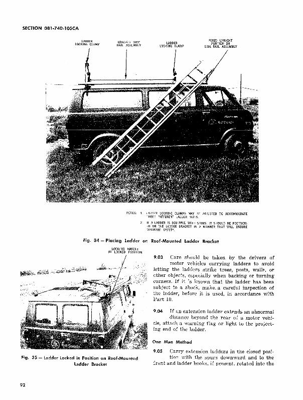
(3) Lower the base of the ladder to the ground and position the top portion of the ladder
behind the rolled upright portion of the outside side rail assembly as shown in Fig. 34.
( 4) Raise the base of the ladder and place it in position in the ladder bracket.
(5) Lock the ladder in place as shown in Fig. 35.
For removing the ladder from the truck reverse the procedure listed above. Caution must be exercised not to drop the foot of the ladder as this will damage the spurs.
Note: The steps outlined in Para. 9.02 are for a typical roof-mounted ladder bracket. Other types of ladder brackets are available and the method of placing ladders in these
brackets may vary.
9i
SECTION 081-7 40-1 OSCA
LADDER LOCKING CLAMP
BRACKET SIDE RAIL ASSEMBLY
LADDER LOCKING CLAMP
FIXED UPRIGHT PORTION ON
SIDE RAIL ASSEMBLY
NOTES: 1. lADDER LOCKING CLAMPS MAY BE ADJUSTED TO ACCOMMODATE THREE DltFERENT LADDER SIZES.
2. IF A LADDER IS EQUIPPED WITH SPURS, IT SHOULD BE POSIT!ONED ON THE LADDER BRACKET IN A MANNER THAT WILL ENSURE MAXIMUM SAFETY.
Fig. 34 - Placing Ladder on Roof-Mounted ladder Bracket
lOCKING HANDLE IN LOCKED POSITION
Fig. 35- Ladder Locked in Position on Roof-Mounted Ladder Bracket
92
9.03 Care should be taken by the drivers of motor vehicles carrying ladders to avoid
letting the ladders strike trees, posts, walls, or other objects, especially when backing or turning corners. If it is known that the ladder has been subject to a shock, make. a careful inspection of the ladder, before it is used, in accordance with Part 10.
9.04 If an extension ladder extends an abnormal distance beyond the rear of a motor vehi
cle, attach a warning flag or light to the projecting end of the ladder.
One Man Method
9.05 Carry extension ladders in the closed position with the spurs downward and to the
front and ladder hooks, if present, rotated into the
plane of the rungs between the side rails. Secure the end of the ladder rope by tying it with a clove
hitch around one rung of the top section and the
adjacent rung of the bottom section.
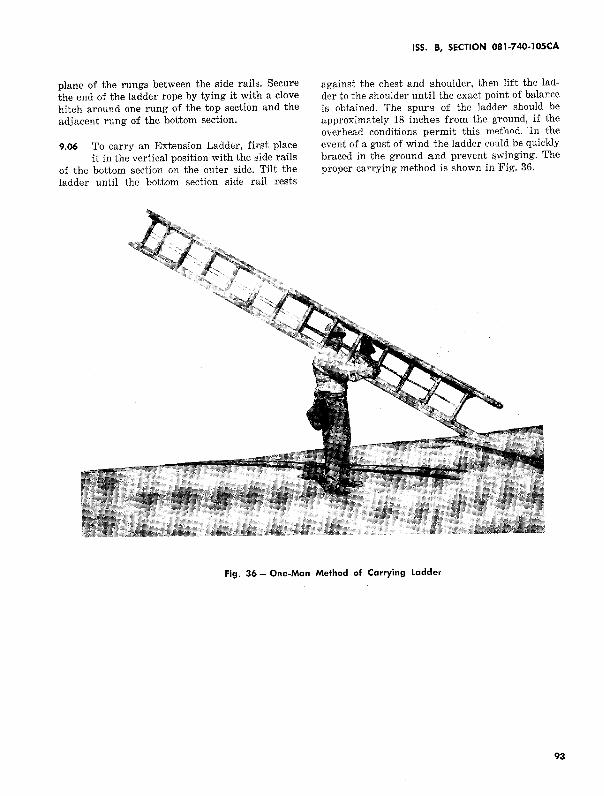
9.06 To carry an Extension Ladder, first place it in the vertical position with the side rails
of the bottom section on the outer side. Tilt the ladder until the bottom section side rail rests
ISS. 8, SECTION 081-740-lOSCA
against the chest and shoulder, then lift the ladder to the shoulder until the exact point of balance is obtained. The spurs of the ladder should be approximately 18 inches from the ground, if the overhead conditions permit this method. In the event of a gust of wind the ladder could be quickly braced in the ground and prevent swinging. The proper carrying method is shown in Fig. 36.
Fig. 36- One-Man Method of Carrying Ladder
93
SECTION 081-740-lOSCA
9.07 Do not lift or carry a ladder by grasping the ladder rope.
Two Man Method
9.08 Before carrying the ladder, secure the free end of the ladder rope with a clove hitch
around one rl)ng of the top section and the adja-
cent rung of the bottom section. Rotate the ladder hooks, if present, into the plane of the rungs, between the side rails.
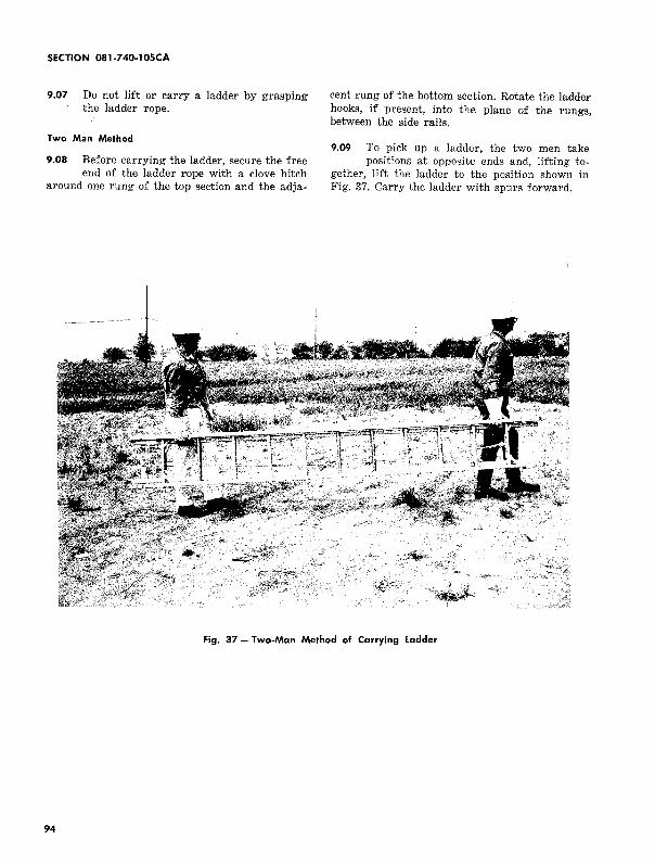
9.09 To pick up a ladder, the two men take positions at opposite ends and, lifting to
gether, lift the ladder to the position shown in Fig. 37. Carry the ladder with spurs forward.
Fig. 37 - Two-Man Method of Carrying Ladder
94
10. INSPECTION OF EXTENSION LADDERS
Inspection Routine
10.01 Each person using a ladder shall deter-mine that it is in good condition and that
its appearance indicates neither deterioration nor damage sufficient to affect its strength. Ladders not in storage shall be examined visually once each week as outlined in Paras. 11.01 through 11.09. Should such examination reveal a split, splinter etc., in a side rail, the sections shall be inspected as outlined in Paras. 10.06 through 10.10. The sections shall also be examined under the prescribed dead-weight load inspection in the event the ladder has been dropped or has otherwise been abused or damaged or every 6 months.
10.02 The definitions of some terms used in inspecting ladders are as follows:
• Cracks are fractures across the lengthwise fibers of the wood resulting usually from mechanical stresses.
• Decay is disintegration of the wood due to action of wood-destroying fungi.
• Splits are lengthwise separations of the wood extending in the direction of the grain.
10.03 The inspection of extension ladders shall be made when the wood is dry. Absorp
tion of considerable moisture causes swelling which tends to conceal defects.
10.04 The supervisor shall inspect the ladders used by his forces at least every two
months. Inspection under dead weight load may be omitted in this inspection.
10.0S The supervisor shall see that the craftsmen comply with the inspection routine.
Method of Inspection
10.06 Examine the ladder to determine the condition of all of its parts. In order to
facilitate careful inspection, place the ladder at a convenient height in a well lighted area. If any defects are found which cannot be taken care
ISS. B, SECTION 081-740-105CA
of by the craftsman or if the condition is such that there is doubt about the ladder being safe to use, exchange it at once, in accordance with local routine, for one in good condition.
Dead Weight Test
10.07 Separate the ladder sections and place one section at a time on two supports located
a few inches from the ends of the side rails. These supports should be of a height which will permit the craftsman to examine the underside of each rail thoroughly.
10.08 Place a weight of approximately 100 pounds (3 coils of drop wire) at a point
approximately 2 feet from one end support. The weight should be supported approximately evenly by the two side rails. Examine the under edges and the faces of each rail carefully for signs of the defects described in Paras. 11.01 through 11.09. Particular attention should be given to the points where the rungs are joined to the side rails, as these are points where fractures are most likely to occur.
10.09 Repeat the operation in Para. 10.08 with the weight placed at the midpoint of the
ladder section and again with the weight placed about 2 feet from the other support.
10.10 Turn the section over and repeat the inspections outlined in Paras. 10.08 and
10.09 above. The suggested loading is not a strength test of the section, but rather a means for disclosing defects and, therefore is of no significance unless a careful visual examination is carried out while the section is under load. Under no circumstances shall an extended ladder be inspected in this manner nor shall a weight appreciably in excess of the specified 100 pounds (such as the weight of a person) be applied to a ladder section being inspected.
11. DEFECTS TO LOOK FOR ON LADDER RAILS
11.01 Look for damage to the rails which may appear as a fine crack, as a fold or crease
in the wood fibers, or as a splintering of the wood fibers. Such defects are usually caused by over-
95
SECTION 081-740-105CA
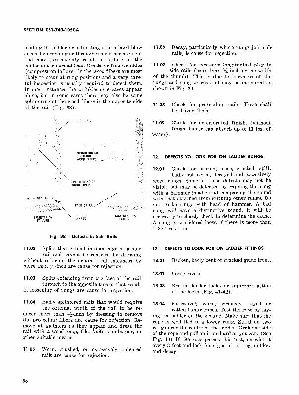
loading the ladder or subjecting it to a hard blow either by dropping or through some other accident and may subsequently result in failure of the ladder under normal load. Cracks or fine wrinkles (compression failure) in the wood fibers are most likely to occur at rung positions and a very careful inspection is usually required to detect them. In most instances the wrinkles or creases appear alone, but in some cases there may also be some splintering of the wood fibers in the opposite side of the rail (Fig. 38).
·r
/ EDGE DF RAIL
/" ~ WRINKLING OR BUCKLING OF
I WOOD FIBERS --
: """ '"'"" . WOOD FIBERS
FACE DF RAIL/,,,',
SPLINTERING FAILURE
COMPRESSION FAILURE
Fig. 38 - Defects in Side Rails
11.02 Splits that extend into an edge of a side rail and cannot be removed by dressing
without reducing the original rail thickness by more than 3;i1-inch are cause for rejection.
11.03 Splits extending from one face of the rail through to the opposite face or that result
in loosening of rungs are cause for rejection.
11.04 Badly splintered rails that would require the original width of the rail to be re
duced more than 112-inch by dressing to remove the projecting fibers are cause for rejection. Remove all splinters as they appear and dress the rail with a wood rasp, file, knife, sandpaper, or other suitable means.
11.05 Worn, crushed, or excessively indented rails are cause for rejection.
96
11.06 Decay, particularly where rungs join side rails, is cause for rejection.
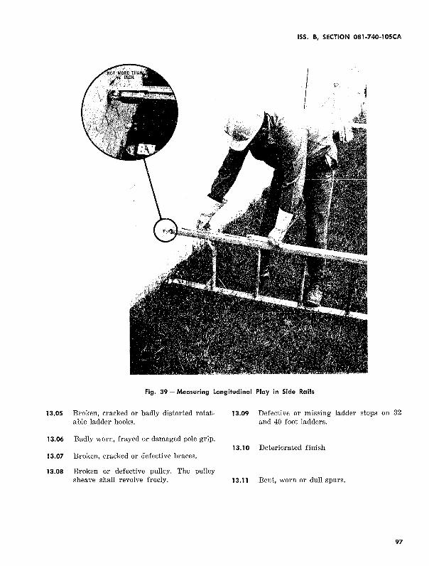
11.07 Check for excessive longitudinal play in side rails (more than %-inch or the width
of the thumb). This is due to looseness of the rungs and rung braces and may be measured as shown in Fig. 39.
11.08 Check for protruding nails. These shall be driven flush.
11.09 Check for deteriorated finish, (without finish, ladder can absorb up to 11 ibs. of
water).
12. DEFECTS TO LOOK FOR ON LADDER RUNGS
12.01 Check for broken, loose, cracked, split, badly splintered, decayed and excessively
worn rungs. Some of these defects may not be visible but may be detected by rapping the rung with a hammer handle and comparing the sound with that obtained from striking other rungs. Do not strike rungs with head of hammer. A bad rung will have a distinctive sound. It will be necessary to closely check to determine the cause. A rung is considered loose if there is more than 1/32" rotation.
13. DEFECTS TO LOOK FOR ON LADDER FITTINGS
13.01 Broken, badly bent or cracked guide irons.
13.02 Loose rivets.
13.03 Broken ladder locks or improper action of the locks (Fig. 41-42).
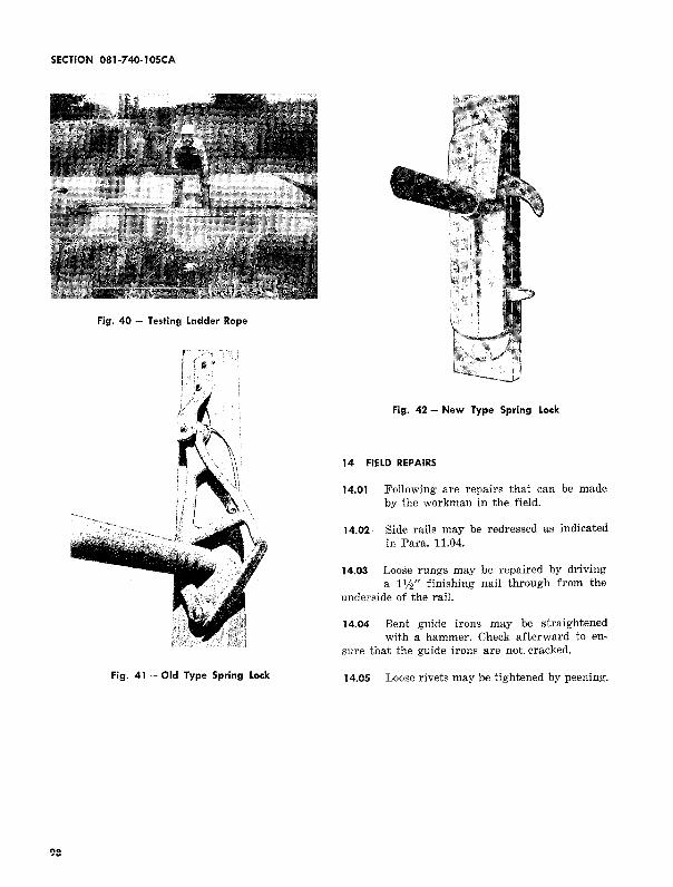
13.04 Excessively worn, seriously frayed or rotted ladder ropes. Test the rope by lay
ing the ladder on the ground. Make sure that the rope is well tied to a lower rung. Stand on two rungs near the centre of the ladder. Grab one side of the rope and pull on it, as hard as you can. (See Fig. 40) If the rope passes this test, untwist it every 3 feet and look for signs of rotting, mildew and decay.
ISS. B, SECTION 081-740-IOSCA
Fig. 39- Measuring Longitudinal Play in Side Rails
13.05 Broken, cracked or badly distorted rotat- 13.09 Defective or m1ssmg ladder stops on 32 able ladder hooks. and 40 foot ladders.
13.06 Badly worn, frayed or damaged pole grip. 13.10 Deteriorated finish
13.07 Broken, cracked or defective braces.
13.08 Broken or defective pulley. The pulley sheave shall revolve freely. 13.11 Bent, worn or dull spurs.
97
SECTION 081-7 40-1 OSCA
Fig. 40 - Testing Ladder Rope
Fig. 41 - Old Type Spring Lock
98
Fig. 42 - New Type Spring Lock
14 FIELD REPAIRS
14.01 Following are repairs that can be made by the workman in the field.
14.02 Side rails may be redressed as indicated in Para. 11.04.
14.03 Loose rungs may be repaired by driving a 1112" finishing nail through from the
underside of the rail.
14.04 Bent guide irons may be straightened with a hammer. Check afterward to en
sure that the guide irons are not. cracked.
14.05 Loose rivets may be tightened by peening.
14.06 Tight ladder locks should be oiled. If the tightness is caused by the swelling of the
wood, the rivet holding the lock can be countersunk slightly to free the lock. This should be done only when the wood is wet.
14.07 Replace ladder ropes.
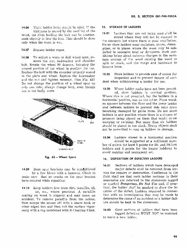
14.08 To adjust a worn or dull wheel spur, re-move the nut, lockwasher and shoulder
bolt. Rotate the wheel 90 degrees, bringing the unused portion of the wheel in position for use. Replace the bolt with the shoulder properly seated in the plate and wheel. Replace the lockwasher and the nut and tighten securely. (See Fig. 43) Do not change the position of a wheel spur on only one side; always change both, even though one is not badly worn.
SHOULDER BOLT
Fig. 43 - Wheel Spurs
14.09 Bent spur brackets may be stratghtened by a few blows with a hammer. Check to
make sure that no cracks on the spur bracket have occured while repairing.
14.10 Keep ladders free from dirt, paraffin, oil, tar, etc., where practical. A paraffin
coating on wood is slippery and may cause an accident. To remove paraffin from the ladder, first scrape the excess off with a shave hook or other edged tool and then rub the surface vigorously with a rag moistened with B Cleaning Fluid.
ISS. B, SECTION 081-740-105CA
15. STORAGE OF LADDERS
15.01 Ladders that are not being used shall be stored where they will not be exposed to
the elements but where there is good ventilation. Never store ladders near radiators, stoves, steampipes, or in places where the wood may be subjected to excessive heat or dampness. Such conditions bring about extreme changes in the moisture content of the wood causing the wood to split or crack, and the rungs and hardware to become loose.
15.02 Store ladders to provide ease of access for inspection and to prevent danger of acci
dent when withdrawing a ladder for use.
15.03 Where ladder racks have not been provid-ed, store ladders in vertical position.
Where this is not practical, lay the ladders in a horizontal position, one on the other. Place wooden spacers between the floor and the lower ladder and between ladders to prevent side rails from becoming damaged by guide irons. Do not store ladders in any position where there is a chance of pressure being placed on them that might cause warping or twisting. Not more than six ladders should be placed in one stack. Heavy objects shall not be permitted to rest on ladders in storage.
15.04 Ladders stored in a horizontal position should be supported at a sufficient num
ber of points (at least 3 points for 20- and 24-foot ladders and 4 points for the longer ladders) to avoid sagging and permanent set.
16. DISPOSITION OF DEFECTIVE LADDERS
16.01 Sections of ladders which have developed major defects shall be removed from ser
vice for repairs or destruction. Craftsmen in the field shall see that such ladder sections in their possession are returned to the storeroom tagged or marked Dangerous, Do Not Use and, if practical, the ladder shall be marked to show the location of the defect. Ladders required in connection with an investigation that may be made to determine the cause of an accident or a ladder failure should be kept in the storeroom.
16.02 Good sections of ladders that have been tagged defective MUST NOT be matched
to make a new ladder.
99