Embed Size (px)
Citation preview
FR200 Series Vector control inverter
- 1 -
Preface
Thank you for choosing FRECON developed and produced FR200 seriesvector control inverter.
FR200 series vector control inverter is mainly positioned as a high-end market for OEMcustomers and the specific requirements of fan and pump load applications,its flexible design, bothembedded SVC and VF control in one,can be widely used for speed control accuracy, torqueresponse speed, low-frequency output characteristics and other situations with higher requirements.
This user manual supplies a detailed description of FR200 series vector control inverter includesproduct characterization, structural features, parameter setting, operation and commissioning,inspection maintenance and other contents. Be sure to carefully read through the safety precautionsbefore use, and use this product on the premise that personnel and equipment safety is ensured.
IMPORTANT NOTESTo illustrate the details of the products,pictures in this manual based on products with outercasing or safety cover being removed. When using this product, please be sure to well installouter casing or covering by the rules, and operating in accordance with the manual contents.The illustrations this manual for illustration only and may vary with different products you haveordered.The company is committed to continuous improvement of products, product features willcontinue to upgrade, the information provided is subject to change without notice.If you are using have questions, please contact our regional agents or our customer servicecenter. Customer Service Tel 0755 -33067999.The company's other products please visit our website.http://www.frecon.com.cn

FR200 Series Vector control inverter
- 2 -
FR200 Series Vector control inverter
- 3 -
Contents
Preface............................................................................................................................................................- 1 -
Contents......................................................................................................................................................... - 3 -
Chapter 1 Safety Precautions................................................................................................................... - 5 -
1.1 Safety Considerations....................................................................................................................... - 5 -1.2 Precautions......................................................................................................................................... - 7 -
Chapter 2 Product Information................................................................................................................. - 9 -
2.1 Nameplate information...................................................................................................................... - 9 -2.2 Information of FR200 Product Model............................................................................................ - 10 -2.3 Technical Features of FR200.........................................................................................................- 11 -2.4 Parts Drawing................................................................................................................................... - 14 -2.5 Configuration, Mounting Dimensions and Weight....................................................................... - 14 -2.6 Wall mounting dimensions..............................................................................................................- 16 -2.7 External Dimensions of Keypad.....................................................................................................- 18 -
Chapter 3 Installation and Wiring.......................................................................................................... - 19 -
3.1 Installation Environment..................................................................................................................- 19 -3.2 Installation Direction, Space and Cooling.....................................................................................- 19 -3.3 Fixed manner....................................................................................................................................- 21 -3.4 Remove & Mount Keypad and Cover........................................................................................... - 23 -3.5 Dust cover installation and removal(Optional accessories)..................................................- 25 -3.6 Configuration of Peripheral Devices..............................................................................................- 26 -3.7 Wiring way........................................................................................................................................ - 28 -3.8 Terminal Configuration....................................................................................................................- 29 -3.9 EMI Solutions................................................................................................................................... - 36 -
Chapter 4 Operation and display........................................................................................................... - 39 -
4.1 Introduction of Keypad.................................................................................................................... - 39 -4.2 Viewing and Modifying Function Codes....................................................................................... - 41 -4.3 Viewing Status Parameters............................................................................................................ - 42 -4.4 Motor Auto-tuning............................................................................................................................ - 42 -4.5 Password Setting............................................................................................................................. - 42 -4.6 Keypad lock...................................................................................................................................... - 42 -
Chapter 5 List of Parameter.................................................................................................................... - 43 -
5.1 Standard Function Parameters...................................................................................................... - 44 -
Chapter 6 Specification of Parameters.................................................................................................- 65 -
Group F00 System Parameters............................................................................................................- 65 -Group F00 Frequency command......................................................................................................... - 68 -Group F02 Start/Stop Control Start/Stop Control...............................................................................- 71 -Group F03 Accel/Decel Parameters.................................................................................................... - 74 -Group F04 Digital Input..........................................................................................................................- 76 -Group F05 Digital Output...................................................................................................................... - 82 -Group F06 Analog and Pulse Input......................................................................................................- 85 -Group F07 Analog and Pulse Output.................................................................................................. - 89 -Group F08 Parameters of Motor 1....................................................................................................... - 90 -Group F09 V/f Control Parameters of Motor 1................................................................................... - 91 -Group F10 Vector Control Parameters of Motor 1.............................................................................- 94 -
FR200 Series Vector control inverter
- 4 -
Group F11 Protection Parameters....................................................................................................... - 96 -Group F12 Multi-Reference and Simple PLC Function.................................................................. - 100 -Group F13 Process PID...................................................................................................................... - 103 -Group F14 Swing Frequency, Fixed Length, Count and Wakeup.................................................- 106 -Group F15 Communication Parameters........................................................................................... - 108 -Group F16 Keys and Display of Keypad Parameters..................................................................... - 109 -Group F17 User-defined Display Parameters.................................................................................. - 110 -Group U00 Status Monitoring............................................................................................................. - 111 -Group U01 Fault Record..................................................................................................................... - 112 -
Chapter 7 Maintenance and Troubleshooting.................................................................................. - 114 -
Chapter 8 Maintenance and Inspection............................................................................................. - 118 -
8.1 Inspection........................................................................................................................................- 118 -8.2 Maintenance................................................................................................................................... - 119 -
Appendix A: Modbus Communication Protocol.............................................................................. - 121 -
Appendix B: Accessories...................................................................................................................... - 127 -
B.1 Braking Resistor............................................................................................................................ - 127 -B.2 Uploading and Downloading Module..........................................................................................- 127 -
FR200 Series Vector control inverter
- 5 -
Chapter 1 Safety Precautions
Safety Precautions
Safety signs in this manual:DANGER: indicates the situation in which the failure to follow operating requirements may result
in fire or serious personal injury or even death.CAUTION: indicates the situation in which the failure to follow operating requirements may cause
moderate or slight injury and damage to equipment.
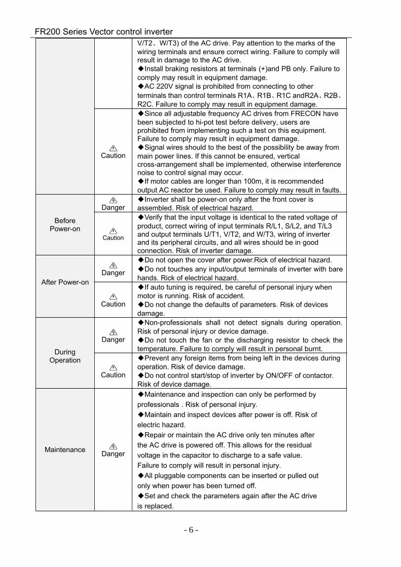
Users are requested to read this chapter carefully when installing, commissioning and repairingthis product and perform the operation according to safety precautions as set forth in this chapterwithout fail. FRECON will bear no responsibility for any injury and loss as a result of any violationoperation.1.1 Safety Considerations
The use phase Safetyclass Considerations
BeforeInstallation
Danger
Do not install the product if the package is with water, orcomponent is missing or broken.Do not install the product if the label on the package is notidentical to that on the inverter.
Caution
Be careful of carrying or transportation. Risk of devicesdamage.Do not use damaged product or the inverters missingcomponent .Risk of injury.Do not touch the parts of control system with bare hands. Riskof ESD hazard.
Installation
Danger
Installation base shall be metal or other non-flammablematerial. Risk of fire.Do not install inverter in an environment containing explosivegases, otherwise there is danger of explosion.Do not unscrew the fixing bolts, especially the bolts with redmark.
Caution
Do not leave cable strips or screws in the inverter. Risk ofinverter damage.Install the product at the place with less vibration and no directsunlight.Consider the installation space for cooling purpose when twoor more inverters are placed in the same cabinet.
Wiring Danger
Wiring must be performed by authorized and qualifiedpersonnel. Risk of danger.Circuit-breaker should be installed between inverter and themains. Risk of fire.Make sure the input power supply has been completelydisconnected before wiring. Failure to comply may result inpersonnel injury and/or equipment damage.Since overall leakage current of this equipment may be biggerthan 3.5mA, for safety's sake, this equipment and its associatedmotor must be well grounded so as to avoid risk of electricshock.Never connect the power cables to the output terminals (U/T1、
FR200 Series Vector control inverter
- 6 -
V/T2、W/T3) of the AC drive. Pay attention to the marks of thewiring terminals and ensure correct wiring. Failure to comply willresult in damage to the AC drive.Install braking resistors at terminals (+)and PB only. Failure tocomply may result in equipment damage.AC 220V signal is prohibited from connecting to otherterminals than control terminals R1A、R1B、R1C andR2A、R2B、R2C. Failure to comply may result in equipment damage.
Caution
Since all adjustable frequency AC drives from FRECON havebeen subjected to hi-pot test before delivery, users areprohibited from implementing such a test on this equipment.Failure to comply may result in equipment damage.Signal wires should to the best of the possibility be away frommain power lines. If this cannot be ensured, verticalcross-arrangement shall be implemented, otherwise interferencenoise to control signal may occur.If motor cables are longer than 100m, it is recommendedoutput AC reactor be used. Failure to comply may result in faults.
BeforePower-on
DangerInverter shall be power-on only after the front cover isassembled. Risk of electrical hazard.
Caution
Verify that the input voltage is identical to the rated voltage ofproduct, correct wiring of input terminals R/L1, S/L2, and T/L3and output terminals U/T1, V/T2, and W/T3, wiring of inverterand its peripheral circuits, and all wires should be in goodconnection. Risk of inverter damage.
After Power-onDanger
Do not open the cover after power.Rick of electrical hazard.Do not touches any input/output terminals of inverter with barehands. Rick of electrical hazard.
Caution
If auto tuning is required, be careful of personal injury whenmotor is running. Risk of accident.Do not change the defaults of parameters. Risk of devicesdamage.
DuringOperation
Danger
Non-professionals shall not detect signals during operation.Risk of personal injury or device damage.Do not touch the fan or the discharging resistor to check thetemperature. Failure to comply will result in personal burnt.
Caution
Prevent any foreign items from being left in the devices duringoperation. Risk of device damage.Do not control start/stop of inverter by ON/OFF of contactor.Risk of device damage.
Maintenance Danger
Maintenance and inspection can only be performed byprofessionals . Risk of personal injury.Maintain and inspect devices after power is off. Risk ofelectric hazard.Repair or maintain the AC drive only ten minutes afterthe AC drive is powered off. This allows for the residualvoltage in the capacitor to discharge to a safe value.Failure to comply will result in personal injury.All pluggable components can be inserted or pulled outonly when power has been turned off.Set and check the parameters again after the AC driveis replaced.
FR200 Series Vector control inverter
- 7 -
1.2 Precautions1.2.1 Motor Insulation Inspection
When the motor is used for the first time or when the motor is reused after being kept, or whenperiodical inspection is performed, insulation inspection shall be conducted with motor so as to avoiddamaging the inverter because of the insulation failure of the motor windings. The motor wires must bedisconnected from the inverter during the insulation inspection. It is recommended to use the 500Vmega meter, and the insulating resistance measured shall be 5MΩ at least.1.2.2 Motor Thermal Protection
If the motor rating does not match that of the inverter, especially when the rated power of theinverter is higher than that of the motor, adjust motor protection parameters in the inverter or installthermal relay to protect motor.1.2.3 Operating with the Frequency Higher than Grid Power Frequency
Output frequency of FR200 is 0.00Hz~600.00Hz. If FR200 is required to operate above 50.00Hz,please take the endurance of mechanical devices into consideration.1.2.4 Mechanical Vibrations
Inverter may encounter mechanical resonance point of the load device at certain outputfrequencies which can be avoided by setting the skip frequency parameters of the inverter.1.2.5 Motor Heat and Noise
Since output voltage of inverter is PWM wave and contains a certain amount of harmonics, sothat the temperature, noise and vibration of the motor will be higher than those when the inverter runsat grid power frequency.1.2.6 Voltage-sensitive device or capacitor on output side of the AC drive
Do not install the capacitor for improving power factor or lightning protection voltage-sensitiveresistor on the output side of the AC drive because the output of the AC drive is PWM wave.Otherwise, the AC drive may suffer transient overcurrent or even be damaged.1.2.7 Contactor at the I/O terminal of the AC drive
When a contactor is installed between the input side of the AC drive and the power supply, the ACdrive must not be started or stopped by switching the contactor on or off. If the AC drive has to beoperated by the contactor, ensure that the time interval between switching is at least one hour sincefrequent charge and discharge will shorten the service life of the capacitor inside the AC drive.When a contactor is installed between the output side of the AC drive and the motor, do not turn off thecontactor when the AC drive is active. Otherwise, modules inside the AC drive may be damaged.1.2.8 Applied with the Rated Voltage
Apply FR200 with the rated voltage. Failure to comply will damage inverter. If required, take atransformer to boost or step-down voltage.1.2.9 Do Not Apply a 3-Phase Input Inverter to 2-Phase Input Applications
Do not apply a 3-phase input FR inverter to 2-phase input applications. Otherwise, it will result infaults or damage inverter.1.2.10 Lightning Protection
FR200 has integrated lightning over-current protection device which has certain self-protectioncapacity against the lightning. Additional protection devices have to be installed between inverterand power supply in the area where lightning occurs frequently.1.2.11 Altitude De-rating
In places where the altitude is above 1000 m and the cooling effect reduces due to thin air, it isnecessary to de-rate the AC drive. Contact FRECON for technical support.1.2.12 some special usages
If wiring that is not described in this manual such as common DC bus is applied, contact the agentor FRECON for technical support.1.2.13 Cautions for Inverter Disposal
The electrolytic capacitors on the main circuit and PCBA may explode when they are burnt.Emission of toxic gas may be generated when the plastic parts are burnt. Please dispose inverter asindustrial wastes.1.2.14 Adaptable Motor
The standard adaptable motor is adaptable four-pole squirrel-cage asynchronous induction motoror PMSM. For other types of motor, select a proper AC drive according to the rated motor current.
The cooling fan and rotor shaft of non-variable-frequency motor are coaxial, which results inreduced cooling effect when the rotational speed declines. If variable speed is required, add a morepowerful fan or replace it with variable-frequency motor in applications where the motor overheatseasily.

FR200 Series Vector control inverter
- 8 -
The standard parameters of the adaptable motor have been configured inside the AC drive. It isstill necessary to perform motor auto-tuning or modify the default values based on actual conditions.Otherwise, the running result and protection performance will be affected.
The AC drive may alarm or even be damaged when short-circuit exists on cables or inside themotor. Therefore, perform insulation short-circuit test when the motor and cables are newly installed orduring routine maintenance. During the test, make sure that the AC drive is disconnected from thetested parts.
FR200 Series Vector control inverter
- 9 -
Chapter 2 Product Information
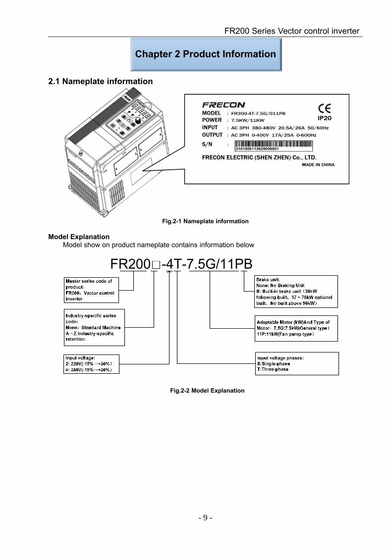
2.1 Nameplate information
Fig.2-1 Nameplate information
Model ExplanationModel show on product nameplate contains information below
Fig.2-2 Model Explanation
FR200 Series Vector control inverter
- 10 -
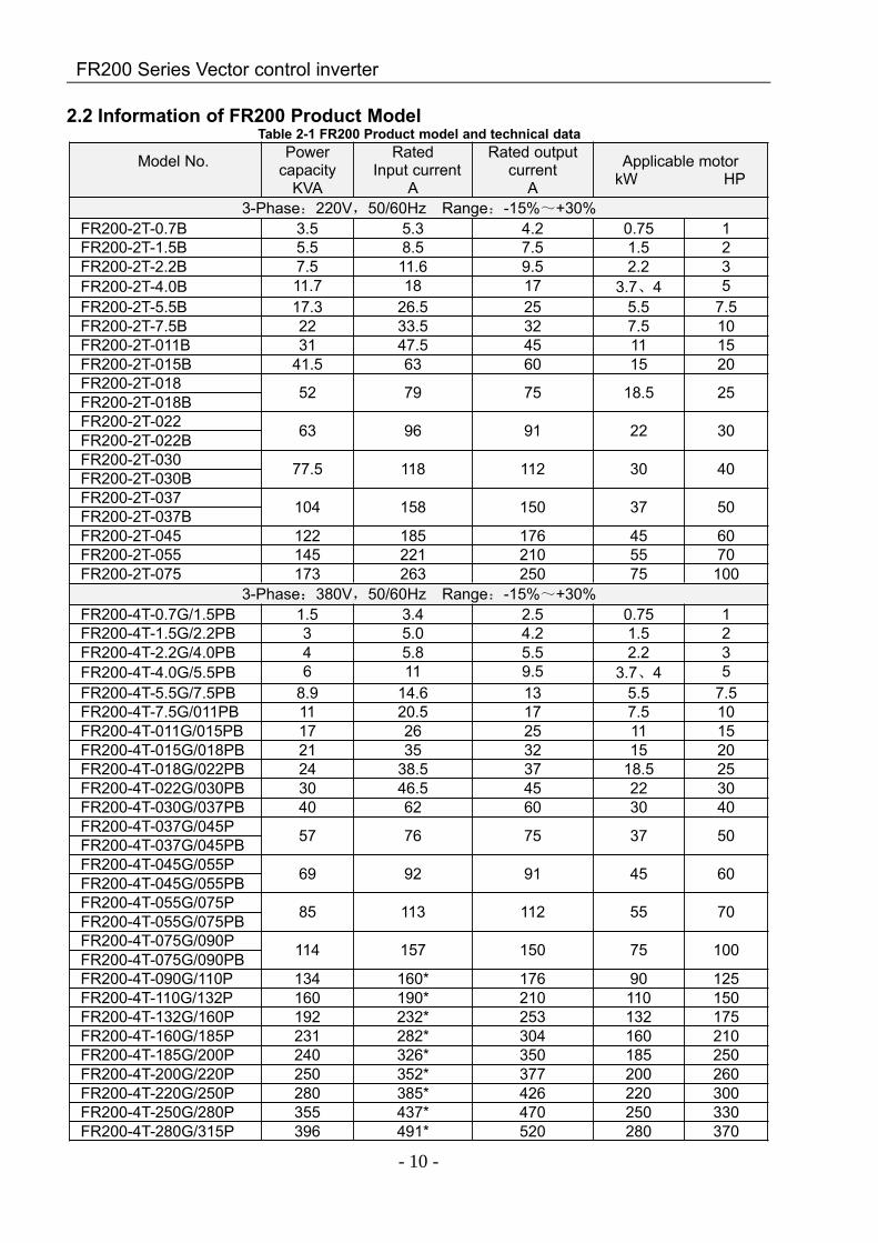
2.2 Information of FR200 Product ModelTable 2-1 FR200 Product model and technical data
Model No. Powercapacity
KVA
RatedInput current
A
Rated outputcurrent
A
Applicable motorkW HP
3-Phase:220V,50/60Hz Range:-15%~+30%FR200-2T-0.7B 3.5 5.3 4.2 0.75 1FR200-2T-1.5B 5.5 8.5 7.5 1.5 2FR200-2T-2.2B 7.5 11.6 9.5 2.2 3FR200-2T-4.0B 11.7 18 17 3.7、4 5FR200-2T-5.5B 17.3 26.5 25 5.5 7.5FR200-2T-7.5B 22 33.5 32 7.5 10FR200-2T-011B 31 47.5 45 11 15FR200-2T-015B 41.5 63 60 15 20FR200-2T-018 52 79 75 18.5 25FR200-2T-018BFR200-2T-022 63 96 91 22 30FR200-2T-022BFR200-2T-030 77.5 118 112 30 40FR200-2T-030BFR200-2T-037 104 158 150 37 50FR200-2T-037BFR200-2T-045 122 185 176 45 60FR200-2T-055 145 221 210 55 70FR200-2T-075 173 263 250 75 100
3-Phase:380V,50/60Hz Range:-15%~+30%FR200-4T-0.7G/1.5PB 1.5 3.4 2.5 0.75 1FR200-4T-1.5G/2.2PB 3 5.0 4.2 1.5 2FR200-4T-2.2G/4.0PB 4 5.8 5.5 2.2 3FR200-4T-4.0G/5.5PB 6 11 9.5 3.7、4 5FR200-4T-5.5G/7.5PB 8.9 14.6 13 5.5 7.5FR200-4T-7.5G/011PB 11 20.5 17 7.5 10FR200-4T-011G/015PB 17 26 25 11 15FR200-4T-015G/018PB 21 35 32 15 20FR200-4T-018G/022PB 24 38.5 37 18.5 25FR200-4T-022G/030PB 30 46.5 45 22 30FR200-4T-030G/037PB 40 62 60 30 40FR200-4T-037G/045P 57 76 75 37 50FR200-4T-037G/045PBFR200-4T-045G/055P 69 92 91 45 60FR200-4T-045G/055PBFR200-4T-055G/075P 85 113 112 55 70FR200-4T-055G/075PBFR200-4T-075G/090P 114 157 150 75 100FR200-4T-075G/090PBFR200-4T-090G/110P 134 160* 176 90 125FR200-4T-110G/132P 160 190* 210 110 150FR200-4T-132G/160P 192 232* 253 132 175FR200-4T-160G/185P 231 282* 304 160 210FR200-4T-185G/200P 240 326* 350 185 250FR200-4T-200G/220P 250 352* 377 200 260FR200-4T-220G/250P 280 385* 426 220 300FR200-4T-250G/280P 355 437* 470 250 330FR200-4T-280G/315P 396 491* 520 280 370
FR200 Series Vector control inverter
- 11 -
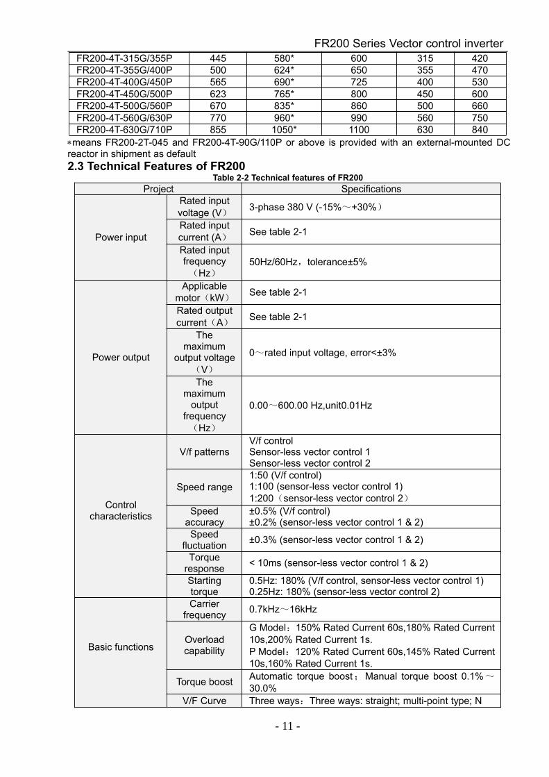
FR200-4T-315G/355P 445 580* 600 315 420FR200-4T-355G/400P 500 624* 650 355 470FR200-4T-400G/450P 565 690* 725 400 530FR200-4T-450G/500P 623 765* 800 450 600FR200-4T-500G/560P 670 835* 860 500 660FR200-4T-560G/630P 770 960* 990 560 750FR200-4T-630G/710P 855 1050* 1100 630 840
∗means FR200-2T-045 and FR200-4T-90G/110P or above is provided with an external-mounted DCreactor in shipment as default2.3 Technical Features of FR200
Table 2-2 Technical features of FR200Project Specifications
Power input
Rated inputvoltage (V) 3-phase 380 V (-15%~+30%)
Rated inputcurrent (A) See table 2-1
Rated inputfrequency(Hz)
50Hz/60Hz,tolerance±5%
Power output
Applicablemotor(kW)
See table 2-1
Rated outputcurrent(A) See table 2-1
Themaximum
output voltage(V)
0~rated input voltage, error<±3%
Themaximum
outputfrequency(Hz)
0.00~600.00 Hz,unit0.01Hz
Controlcharacteristics
V/f patternsV/f controlSensor-less vector control 1Sensor-less vector control 2
Speed range1:50 (V/f control)1:100 (sensor-less vector control 1)1:200(sensor-less vector control 2)
Speedaccuracy
±0.5% (V/f control)±0.2% (sensor-less vector control 1 & 2)
Speedfluctuation ±0.3% (sensor-less vector control 1 & 2)
Torqueresponse < 10ms (sensor-less vector control 1 & 2)
Startingtorque
0.5Hz: 180% (V/f control, sensor-less vector control 1)0.25Hz: 180% (sensor-less vector control 2)
Basic functions
Carrierfrequency 0.7kHz~16kHz
Overloadcapability
G Model:150% Rated Current 60s,180% Rated Current10s,200% Rated Current 1s.P Model:120% Rated Current 60s,145% Rated Current10s,160% Rated Current 1s.
Torque boost Automatic torque boost;Manual torque boost 0.1%~30.0%
V/F Curve Three ways:Three ways: straight; multi-point type; N
FR200 Series Vector control inverter
- 12 -
Th-type V / F curve(1.2 Th -type、1.4 Th -type、1.6 Th-type、1.8 Th -type、2 Th -type)
Accelerationand
decelerationCurve
Line or curve acceleration and deceleration mode.Four kinds of acceleration and deceleration time,RampTime Range :0.0~6000.0s
DC brakeDC brake start frequency: 0.00~600.00HzDC brake time:0.0s~10.0sDC brake current:0.0%~150.0%
Basic functions
Jog brake Jog frequency range:0.00Hz~50.00Hz.Jog deceleration time: 0.0s~6000.0s.
Simple PLC、Multi-speed
Through the built-in PLC or control terminal to achieveup to 16 speed running
Built-in PID Facilitate the realization of process control loop controlsystem
Automaticvoltage
adjustment(AVR)
When the grid voltage changes, can automaticallymaintain a constant output voltage
Fast currentlimit function Minimize over current fault protection inverter running
Over voltageOver current
System automatically limits of current and voltage duringoperation to prevent frequent
Run
Commandsource
Given the control panel, control terminal, serialcommunication port given.
Frequencygiven
Sevkeinradlswoafysfrtoeqsuweintcchy sources: digitalsetting, keyboard potentiometer setting, analogVoltage, given analog current reference pulse is given,the serial port is given, multi-speed given, PLC is given,the process PI D reference. There are several ways toswitch
Input terminal
7 Switch input terminals, one way to make high-speedpulse input.3-channel analog inputs, including 2-way 0~10V / 0~20mA voltage and current options,a way to support -10~+10 V input
outputterminal
2-way switch output terminal, which supports amaximum road speed 100kHz pulse output.2 relay output terminals.2 analog output terminal, and optional voltage andcurrent.
Featuredfunctions
Parameter copy、parameter backup、flexible parameter displayed &hidden. Common DC bus(Contains below 30 KW).Various master & auxiliary command and switchover.Reliable speed search started.A variety of Accel / Decel curves programmable.Timing control、 fixed length control、count function.Three faults recorded.Over excitation brake、overvoltage stall protection programmable、undervoltage stall protection programmable、restart upon power loss.Four kinds of Accel/Decel time.Motor thermal protection.Flexible fan control.Process PID control、simple PLC、16-step speed control programmable.Wobble frequency control.Multi-functional key programmable、field-weakening control.
FR200 Series Vector control inverter
- 13 -
High-precision torque control、V/f separated control、torque control atsensor-less vector control.
Protectionfunction
Provide fault protection dozen:Overcurrent、Overvoltage、Undervoltage、Overtemperature、Overload Etc Protection.
Display andkeyboard
LED Display Display ParametersKey lock and
functionselection
Realize some or all of the keys locked, scope definitionsection keys to prevent misuse
Run and stopmonitoringinformation
In the run or stop can be set to monitor U00 group fourobjects were.
Environment
Place ofoperation
Indoors, no direct sunlight, free from dust, corrosivegases,flammable gases, oil mist, water vapor, water drop andsalt, etc.
Altitude0~2000mDe-rate 1% for every 100m when the altitude is above1000 meters
Ambienttemperature -10~40
Relativehumidity 5~95%, no condensation
Vibration Less than 5.9m/s2 (0.6g)Storage
temperature -20~+70
Others
Efficiency Rated power≥93%Installation Wall-mounted or Flange mountingIP grade IP20Coolingmethod Fan cooled
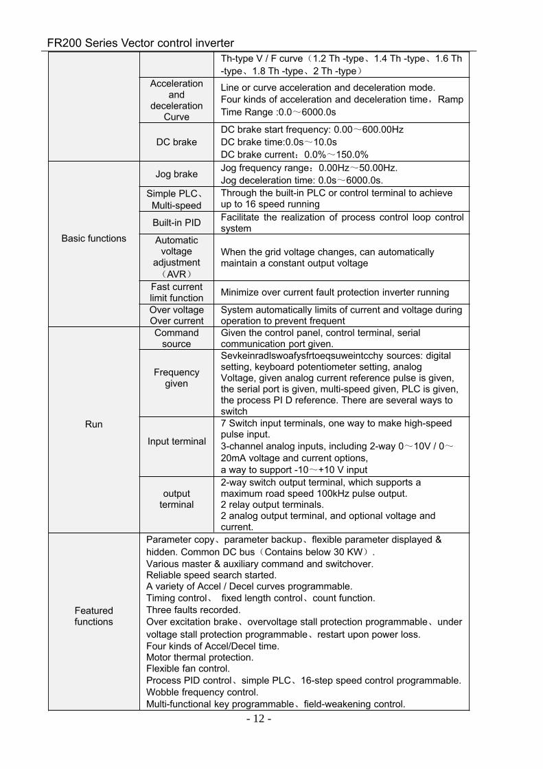
2.4 Parts Drawing
Fig 2-3 0.75~15kW Outline
FR200 Series Vector control inverter
- 14 -
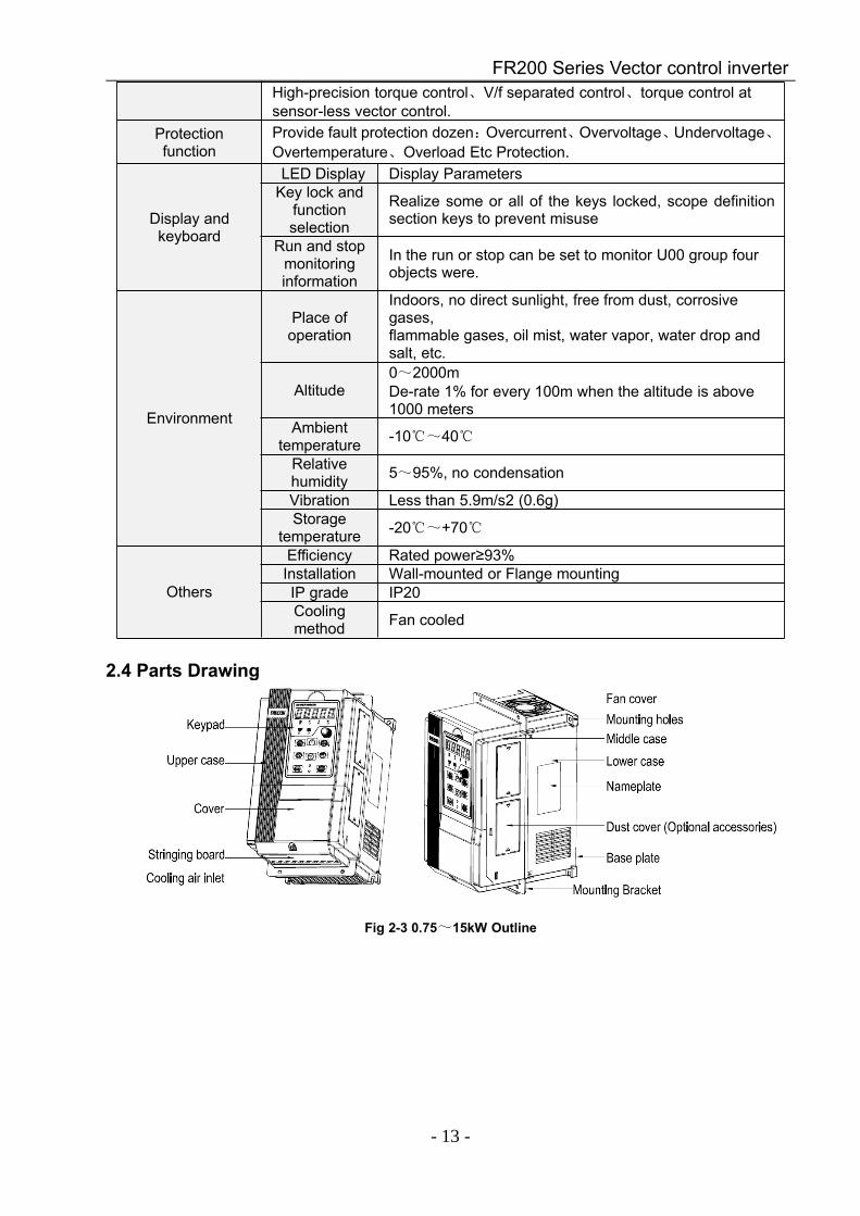
Fig 2-4 18.5~132kW Outline
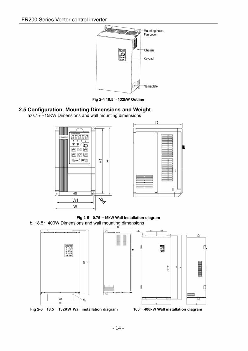
2.5 Configuration, Mounting Dimensions and Weighta:0.75~15KW Dimensions and wall mounting dimensions
Fig 2-5 0.75~15kW Wall installation diagramb: 18.5~400W Dimensions and wall mounting dimensions
Fig 2-6 18.5~132KW Wall installation diagram 160~400kW Wall installation diagram
FR200 Series Vector control inverter
- 15 -
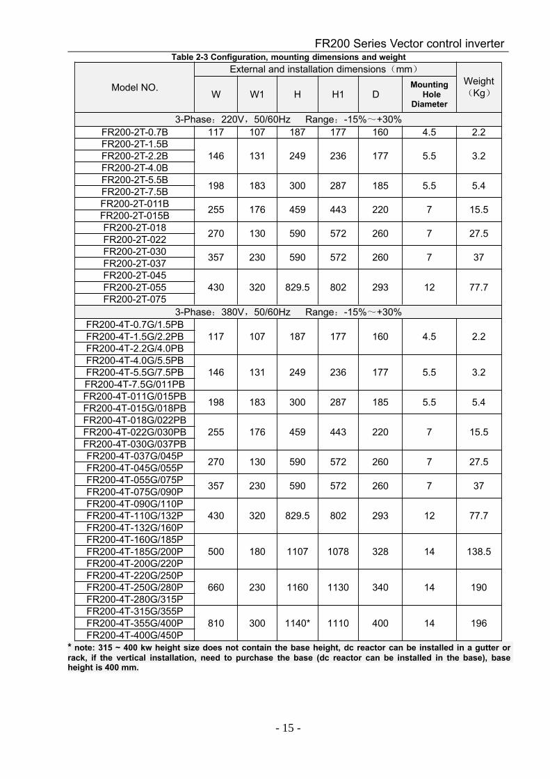
Table 2-3 Configuration, mounting dimensions and weight
Model NO.
External and installation dimensions(mm)Weight(Kg)W W1 H H1 D
MountingHole
Diameter
3-Phase:220V,50/60Hz Range:-15%~+30%FR200-2T-0.7B 117 107 187 177 160 4.5 2.2FR200-2T-1.5B
146 131 249 236 177 5.5 3.2FR200-2T-2.2BFR200-2T-4.0BFR200-2T-5.5B 198 183 300 287 185 5.5 5.4FR200-2T-7.5BFR200-2T-011B 255 176 459 443 220 7 15.5FR200-2T-015BFR200-2T-018 270 130 590 572 260 7 27.5FR200-2T-022FR200-2T-030 357 230 590 572 260 7 37FR200-2T-037FR200-2T-045
430 320 829.5 802 293 12 77.7FR200-2T-055FR200-2T-075
3-Phase:380V,50/60Hz Range:-15%~+30%FR200-4T-0.7G/1.5PB
117 107 187 177 160 4.5 2.2FR200-4T-1.5G/2.2PBFR200-4T-2.2G/4.0PBFR200-4T-4.0G/5.5PB
146 131 249 236 177 5.5 3.2FR200-4T-5.5G/7.5PBFR200-4T-7.5G/011PBFR200-4T-011G/015PB 198 183 300 287 185 5.5 5.4FR200-4T-015G/018PBFR200-4T-018G/022PB
255 176 459 443 220 7 15.5FR200-4T-022G/030PBFR200-4T-030G/037PBFR200-4T-037G/045P 270 130 590 572 260 7 27.5FR200-4T-045G/055PFR200-4T-055G/075P 357 230 590 572 260 7 37FR200-4T-075G/090PFR200-4T-090G/110P
430 320 829.5 802 293 12 77.7FR200-4T-110G/132PFR200-4T-132G/160PFR200-4T-160G/185P
500 180 1107 1078 328 14 138.5FR200-4T-185G/200PFR200-4T-200G/220PFR200-4T-220G/250P
660 230 1160 1130 340 14 190FR200-4T-250G/280PFR200-4T-280G/315PFR200-4T-315G/355P
810 300 1140* 1110 400 14 196FR200-4T-355G/400PFR200-4T-400G/450P
* note: 315 ~ 400 kw height size does not contain the base height, dc reactor can be installed in a gutter orrack, if the vertical installation, need to purchase the base (dc reactor can be installed in the base), baseheight is 400 mm.
FR200 Series Vector control inverter
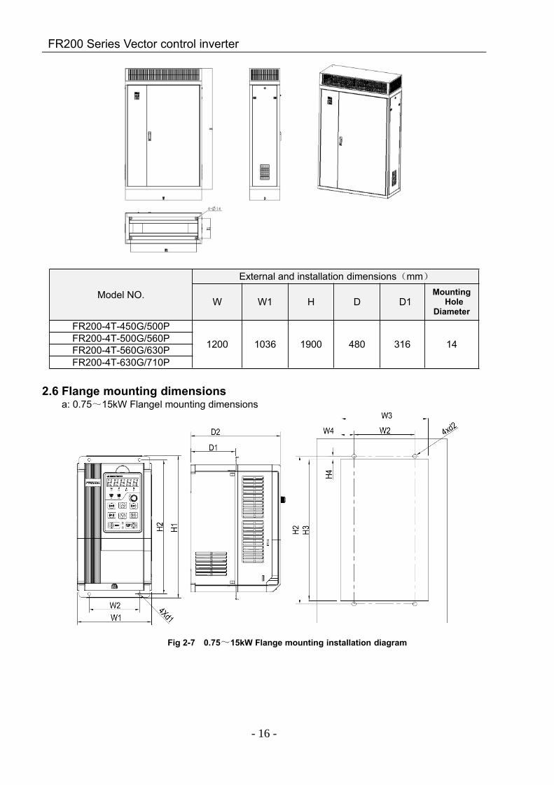
- 16 -
Model NO.
External and installation dimensions(mm)
W W1 H D D1MountingHole
Diameter
FR200-4T-450G/500P
1200 1036 1900 480 316 14FR200-4T-500G/560PFR200-4T-560G/630PFR200-4T-630G/710P
2.6 Flange mounting dimensionsa: 0.75~15kW Flangel mounting dimensions
Fig 2-7 0.75~15kW Flange mounting installation diagram

FR200 Series Vector control inverter
- 17 -
b: 18.5~132kW Flange mounting dimensions
Fig 2-8 18.5~132kW Flange mountingTable 2-4 Flange mounting dimensions table
Model.NO External and installation dimensions(mm)W1 W2 W3 W4 H1 H2 H3 H4 D1 D2 d1 d2
3-Phase:220V,50/60Hz Range:-15%~+30%FR200-2T-0.7B 117 142 124 9 227 209 191 8 53 160 4.5 5
FR200-2T-1.5B146 100 147 21 279 262 251 5.5 88 177 5.5 6FR200-2T-2.2B
FR200-2T-4.0BFR200-2T-5.5B
198 160 199 17 330 313 302 5.5 91 185 5.5 6FR200-2T-7.5BFR200-2T-011B
255 176 257 40.5 460.5 445 427 9.5 110 218 7 7FR200-2T-015BFR200-2T-018
270 130 276 73 591.5 572 554 10.5 109.5 258 7 7FR200-2T-022FR200-2T-030
357 230 361 65.5 591.5 572 554 10.5 109.7 258 7 7FR200-2T-037FR200-2T-045
430 320 436 58 803.5 831.5 775 14 161 291 12 12FR200-2T-055FR200-2T-075
3-Phase:380V,50/60Hz Range:-15%~+30%FR200-4T-0.7G/1.5PB
117 142 124 9 227 209 191 8 53 160 4.5 5FR200-4T-1.5G/2.2PBFR200-4T-2.2GB
FR200-4T-4.0G/5.5PB146 100 147 21 279 262 251 5.5 88 177 5.5 6FR200-4T-5.5G/7.5PB
FR200-4T-7.5G/011PBFR200-4T-011G/015PB
198 160 199 17 330 313 302 5.5 91 185 5.5 6FR200-4T-015G/018PBFR200-4T-018G/022PB
255 176 257 40.5 460.5 445 427 9.5 110 218 7 7FR200-4T-022G/030PBFR200-4T-030G/037PBFR200-4T-037G/045P 270 130 276 73 591.5 572 554 10.5 109.5 258 7 7FR200-4T-045G/055PFR200-4T-055G/075P
357 230 361 65.5 591.5 572 554 10.5 109.7 258 7 7FR200-4T-075G/090PFR200-4T-090G/110P
430 320 436 58 803.5 831.5 775 14 161 291 12 12FR200-4T-110G/132PFR200-4T-132G/160P
FR200 Series Vector control inverter
- 18 -
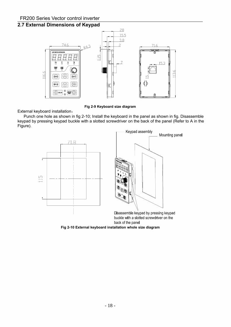
2.7 External Dimensions of Keypad
Fig 2-9 Keyboard size diagramExternal keyboard installation:
Punch one hole as shown in fig 2-10; Install the keyboard in the panel as shown in fig. Disassemblekeypad by pressing keypad buckle with a slotted screwdriver on the back of the panel (Refer to A in theFigure).
Fig 2-10 External keyboard installation whole size diagram
FR200 Series Vector control inverter
- 19 -
Chapter 3 Installation and Wiring
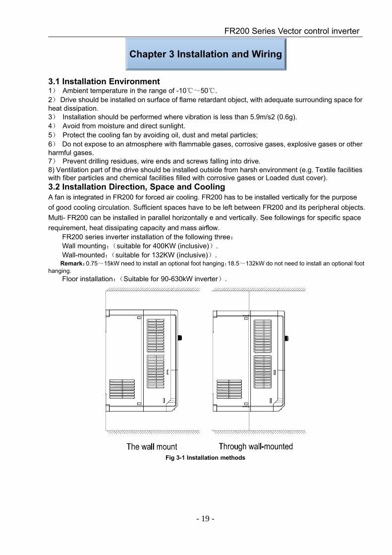
3.1 Installation Environment1) Ambient temperature in the range of -10~50.2)Drive should be installed on surface of flame retardant object, with adequate surrounding space forheat dissipation.3) Installation should be performed where vibration is less than 5.9m/s2 (0.6g).4) Avoid from moisture and direct sunlight.5) Protect the cooling fan by avoiding oil, dust and metal particles;6) Do not expose to an atmosphere with flammable gases, corrosive gases, explosive gases or otherharmful gases.7) Prevent drilling residues, wire ends and screws falling into drive.8) Ventilation part of the drive should be installed outside from harsh environment (e.g. Textile facilitieswith fiber particles and chemical facilities filled with corrosive gases or Loaded dust cover).3.2 Installation Direction, Space and CoolingA fan is integrated in FR200 for forced air cooling. FR200 has to be installed vertically for the purposeof good cooling circulation. Sufficient spaces have to be left between FR200 and its peripheral objects.Multi- FR200 can be installed in parallel horizontally e and vertically. See followings for specific spacerequirement, heat dissipating capacity and mass airflow.
FR200 series inverter installation of the following three:Wall mounting:(suitable for 400KW (inclusive)).Wall-mounted:(suitable for 132KW (inclusive)).Remark:0.75~15kW need to install an optional foot hanging;18.5~132kW do not need to install an optional foot
hanging.Floor installation:(Suitable for 90-630kW inverter).
Fig 3-1 Installation methods
FR200 Series Vector control inverter
- 20 -
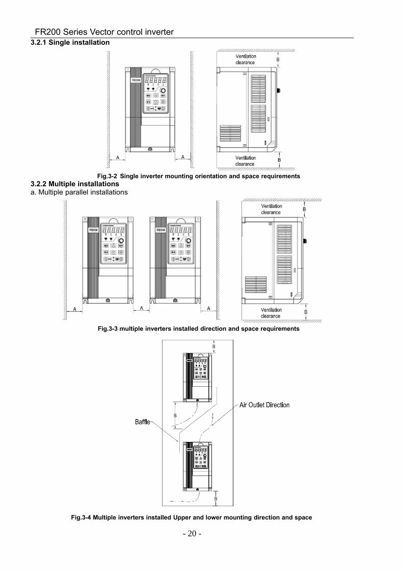
3.2.1 Single installation
Fig.3-2 Single inverter mounting orientation and space requirements3.2.2 Multiple installationsa. Multiple parallel installations
Fig.3-3 multiple inverters installed direction and space requirements
Fig.3-4 Multiple inverters installed Upper and lower mounting direction and space
FR200 Series Vector control inverter
- 21 -
Table 3-1 Requirement of minimum mounting clearances
Drive model Mounting clearances (mm)A B
0.75~15kW ≥50 ≥100
18.5~45kW ≥50 ≥200
55kW and above ≥150 ≥300
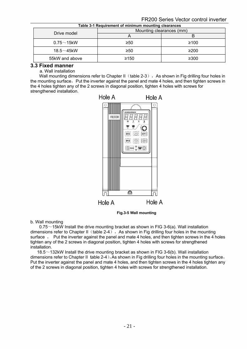
3.3 Fixed mannera. Wall installationWall mounting dimensions refer to Chapter II(table 2-3),As shown in Fig drilling four holes in
the mounting surface,Put the inverter against the panel and mate 4 holes, and then tighten screws inthe 4 holes tighten any of the 2 screws in diagonal position, tighten 4 holes with screws forstrengthened installation.
Fig.3-5 Wall mounting
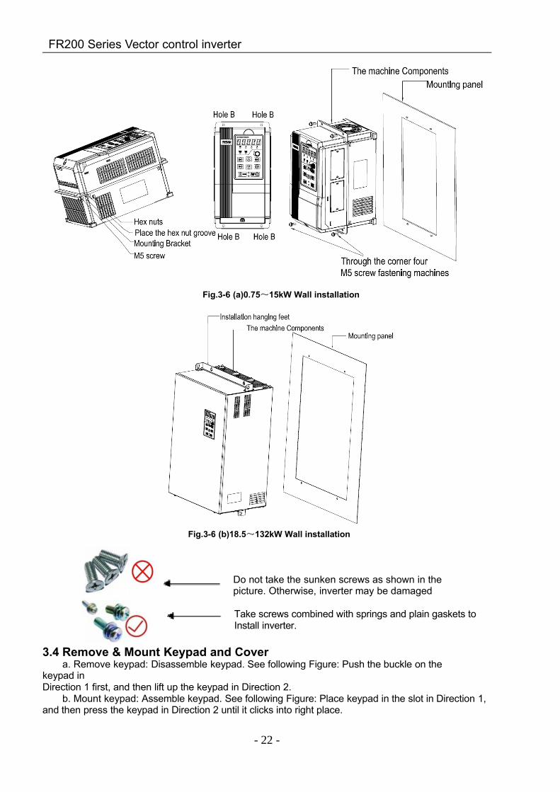
b. Wall mounting0.75~15kW Install the drive mounting bracket as shown in FIG 3-6(a). Wall installation
dimensions refer to Chapter II(table 2-4),As shown in Fig drilling four holes in the mountingsurface , Put the inverter against the panel and mate 4 holes, and then tighten screws in the 4 holestighten any of the 2 screws in diagonal position, tighten 4 holes with screws for strengthenedinstallation.
18.5~132kW Install the drive mounting bracket as shown in FIG 3-6(b). Wall installationdimensions refer to Chapter II(table 2-4),As shown in Fig drilling four holes in the mounting surface,Put the inverter against the panel and mate 4 holes, and then tighten screws in the 4 holes tighten anyof the 2 screws in diagonal position, tighten 4 holes with screws for strengthened installation.
FR200 Series Vector control inverter
- 22 -
Fig.3-6 (a)0.75~15kW Wall installation
Fig.3-6 (b)18.5~132kW Wall installation
Do not take the sunken screws as shown in thepicture. Otherwise, inverter may be damaged
Take screws combined with springs and plain gaskets toInstall inverter.
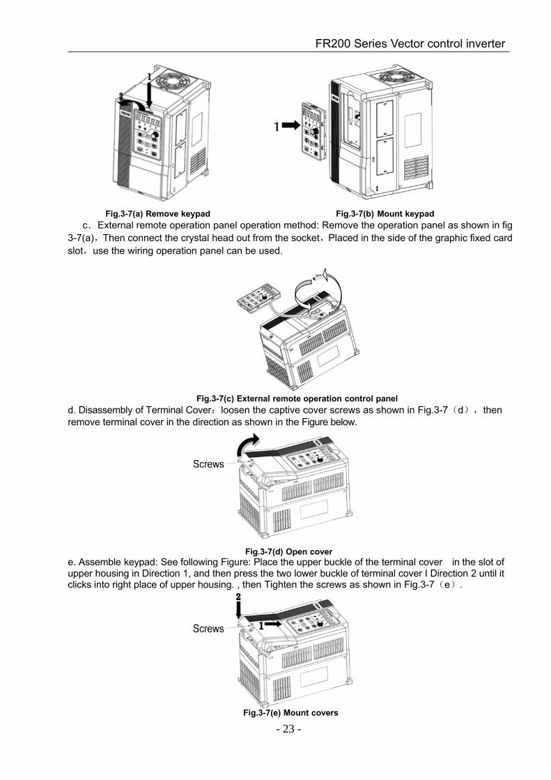
3.4 Remove & Mount Keypad and Covera. Remove keypad: Disassemble keypad. See following Figure: Push the buckle on the
keypad inDirection 1 first, and then lift up the keypad in Direction 2.
b. Mount keypad: Assemble keypad. See following Figure: Place keypad in the slot in Direction 1,and then press the keypad in Direction 2 until it clicks into right place.
FR200 Series Vector control inverter
- 23 -
Fig.3-7(a) Remove keypad Fig.3-7(b) Mount keypadc.External remote operation panel operation method: Remove the operation panel as shown in fig
3-7(a),Then connect the crystal head out from the socket,Placed in the side of the graphic fixed cardslot,use the wiring operation panel can be used.
Fig.3-7(c) External remote operation control paneld. Disassembly of Terminal Cover:loosen the captive cover screws as shown in Fig.3-7(d),thenremove terminal cover in the direction as shown in the Figure below.
Fig.3-7(d) Open covere. Assemble keypad: See following Figure: Place the upper buckle of the terminal cover in the slot ofupper housing in Direction 1, and then press the two lower buckle of terminal cover I Direction 2 until itclicks into right place of upper housing. , then Tighten the screws as shown in Fig.3-7(e).
Fig.3-7(e) Mount covers
1
FR200 Series Vector control inverter
- 24 -
f. Removing and installing the cover method as shown in fig 3-7(f) :First, loosen the screws Thenopen the cover up. According to the assembly when the shell shown method to be assembled in place,and then tighten the screws.
Fig.3-7(f) Disassemble and installation of the coverg. Stringing board disassembly and installation:Disassemble board first when stringing wire,
When connected input and output cables, the Stringing board clicks into place. Referring to fig 3-7(g)
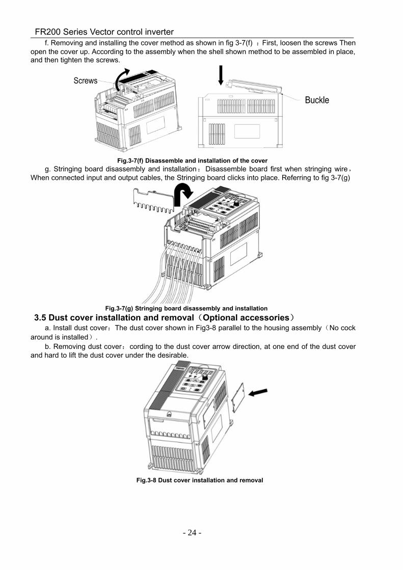
Fig.3-7(g) Stringing board disassembly and installation3.5 Dust cover installation and removal(Optional accessories)
a. Install dust cover:The dust cover shown in Fig3-8 parallel to the housing assembly(No cockaround is installed).
b. Removing dust cover:cording to the dust cover arrow direction, at one end of the dust coverand hard to lift the dust cover under the desirable.
Fig.3-8 Dust cover installation and removal
FR200 Series Vector control inverter
- 25 -
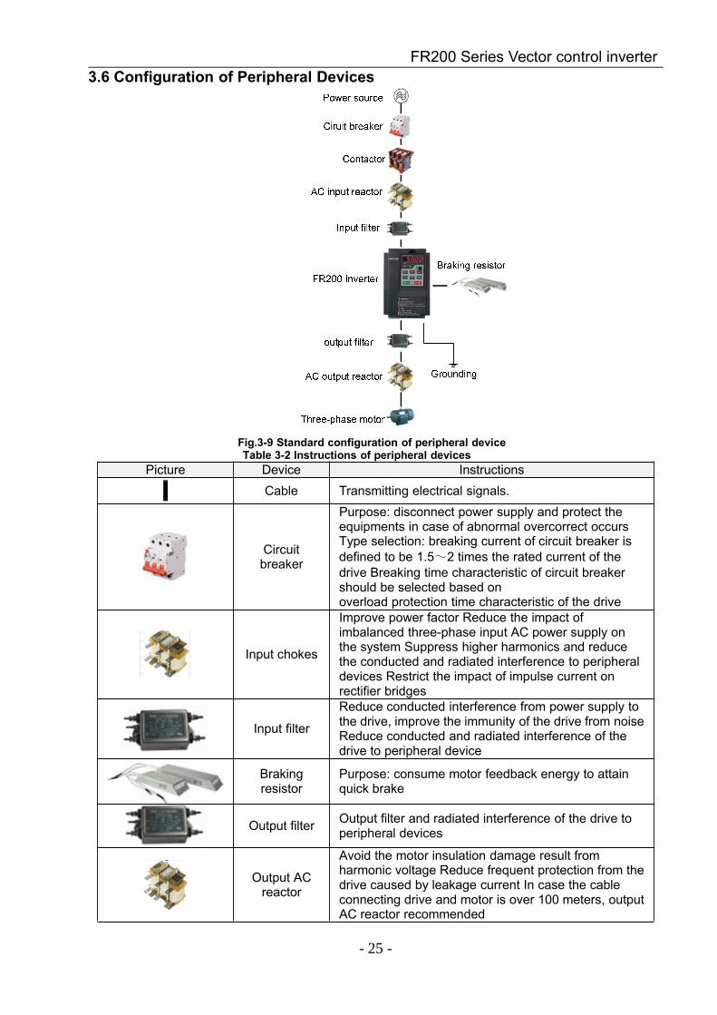
3.6 Configuration of Peripheral Devices
Fig.3-9 Standard configuration of peripheral deviceTable 3-2 Instructions of peripheral devices
Picture Device InstructionsCable Transmitting electrical signals.
Circuitbreaker
Purpose: disconnect power supply and protect theequipments in case of abnormal overcorrect occursType selection: breaking current of circuit breaker isdefined to be 1.5~2 times the rated current of thedrive Breaking time characteristic of circuit breakershould be selected based onoverload protection time characteristic of the drive
Input chokes
Improve power factor Reduce the impact ofimbalanced three-phase input AC power supply onthe system Suppress higher harmonics and reducethe conducted and radiated interference to peripheraldevices Restrict the impact of impulse current onrectifier bridges
Input filter
Reduce conducted interference from power supply tothe drive, improve the immunity of the drive from noiseReduce conducted and radiated interference of thedrive to peripheral device
Brakingresistor
Purpose: consume motor feedback energy to attainquick brake
Output filter Output filter and radiated interference of the drive toperipheral devices
Output ACreactor
Avoid the motor insulation damage result fromharmonic voltage Reduce frequent protection from thedrive caused by leakage current In case the cableconnecting drive and motor is over 100 meters, outputAC reactor recommended

FR200 Series Vector control inverter
- 26 -
3.6.1 Selection of Peripheral DevicesTable 3-3 Selection of peripheral devices
Model.NOCircuit
breaker(A)
Contactor(A)
Powerterminals CableSpecifications
(mm2)
Groundterminal cablespecifications
(mm2)
Terminalscrews
Specifications
3-Phase:220V,50/60Hz Range:-15%~+30%FR200-2T-0.7B 16 10 2.5 2.5 M4FR200-2T-1.5B 25 16 4.0 4.0 M4FR200-2T-2.2B 32 25 4.0 4.0 M4FR200-2T-4.0B 40 32 4.0 4.0 M4FR200-2T-5.5B 63 40 6.0 6.0 M5FR200-2T-7.5B 63 40 6.0 6.0 M5FR200-2T-011B 100 63 10 10 M6FR200-2T-015B 100 63 16 10 M6FR200-2T-018 160 100 16 16 M8FR200-2T-018BFR200-2T-022 200 125 25 16 M8FR200-2T-022BFR200-2T-030 200 125 35 25 M8FR200-2T-030BFR200-2T-037 250 160 50 25 M8FR200-2T-037BFR200-2T-045 250 160 70 35 M10FR200-2T-055 350 350 120 60 M10FR200-2T-075 400 400 150 75 M10
3-Phase:380V,50/60Hz Range:-15%~+30%FR200-4T-0.7G/1.5PB 10 10 2.5 2.5 M4FR200-4T-1.5G/2.2PB 16 10 2.5 2.5 M4FR200-4T-2.2GB 16 10 2.5 2.5 M4FR200-4T-4.0G/5.5PB 25 16 4.0 4.0 M4FR200-4T-5.5G/7.5PB 32 25 4.0 4.0 M4FR200-4T-7.5G/011PB 40 32 4.0 4.0 M4FR200-4T-011G/015PB 63 40 6.0 6.0 M5FR200-4T-015G/018PB 63 40 6.0 6.0 M5FR200-4T-018G/022PB 100 63 10 10 M6FR200-4T-022G/030PB 100 63 10 10 M6FR200-4T-030G/037PB 100 63 16 10 M6FR200-4T-037G/045P 160 100 16 16 M8FR200-4T-037G/045PBFR200-4T-045G/055P 200 125 25 16 M8FR200-4T-045G/055PBFR200-4T-055G/075P 200 125 35 25 M8FR200-4T-055G/075PBFR200-4T-075G/090P 250 160 50 25 M8FR200-4T-075G/090PBFR200-4T-090G/110P 250 160 70 35 M10FR200-4T-110G/132P 350 350 120 60 M10FR200-4T-132G/160P 400 400 150 75 M10FR200-4T-160G/185P 500 400 185 95 M10FR200-4T-185G/200P 600 600 185 95 M10FR200-4T-200G/220P 600 600 150*2 150 M10FR200-4T-220G/250P 600 600 150*2 150 M12FR200-4T-250G/280P 800 600 185*2 95*2 M12FR200-4T-280G/315P 800 800 185*2 95*2 M12FR200-4T-315G/355P 800 800 150*3 75*3 M16
FR200 Series Vector control inverter
- 27 -
FR200-4T-355G/400P 800 800 150*4 75*4 M16FR200-4T-400G/450P 1000 1000 150*4 75*4 M16FR200-4T-450G/500P 1200 1200 180*4 90*4 M16FR200-4T-500G/560P 1200 1200 180*4 90*4 M16FR200-4T-560G/630P 1200 1200 180*4 90*4 M16FR200-4T-630G/710P 1500 1500 180*4 90*4 M16
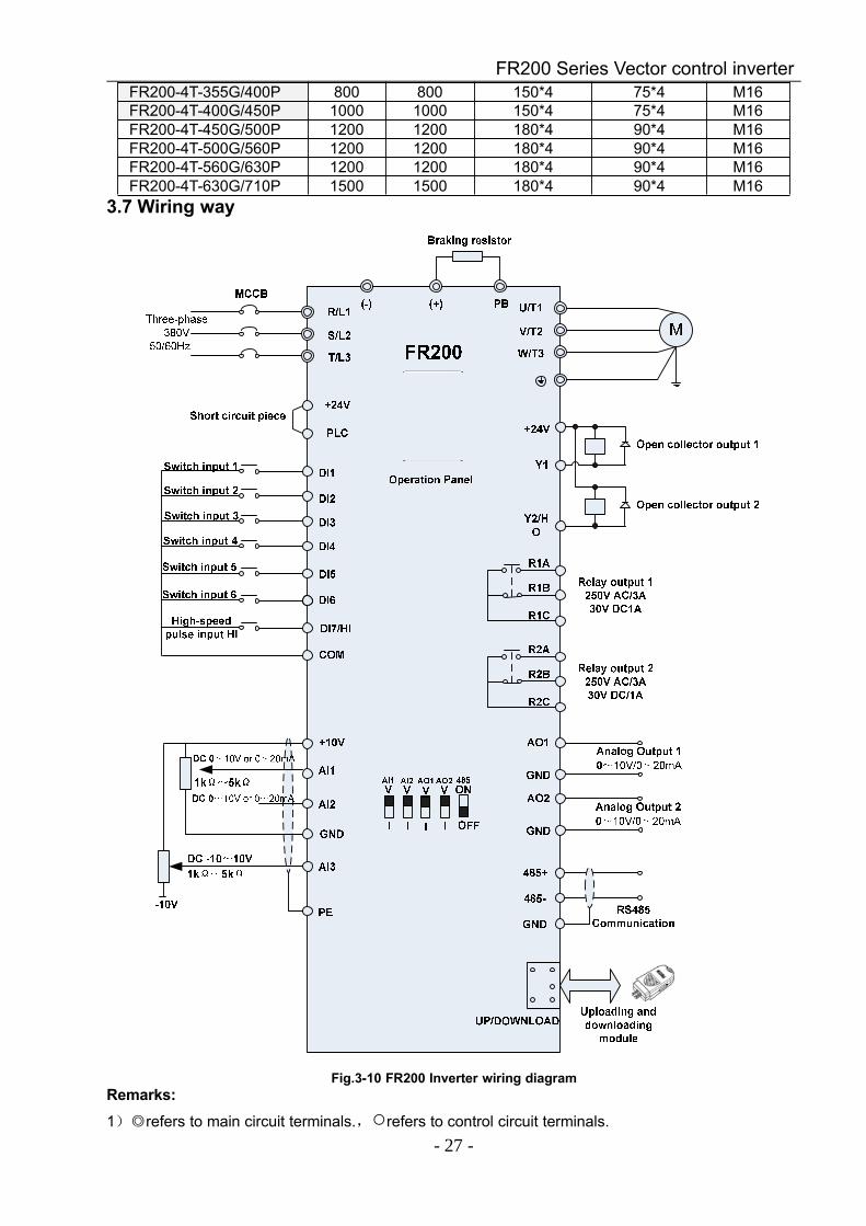
3.7 Wiring way
Fig.3-10 FR200 Inverter wiring diagramRemarks:1)refers to main circuit terminals.,refers to control circuit terminals.
FR200 Series Vector control inverter
- 28 -
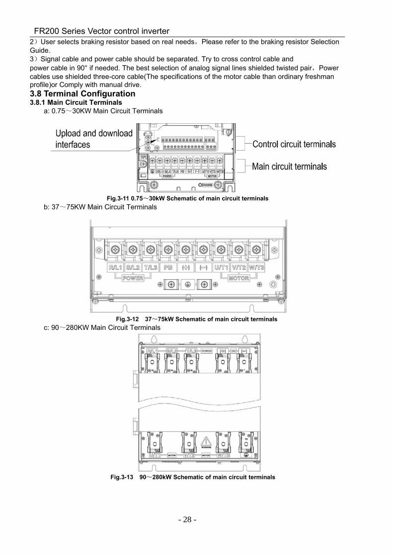
2)User selects braking resistor based on real needs,Please refer to the braking resistor SelectionGuide.3)Signal cable and power cable should be separated. Try to cross control cable andpower cable in 90° if needed. The best selection of analog signal lines shielded twisted pair,Powercables use shielded three-core cable(The specifications of the motor cable than ordinary freshmanprofile)or Comply with manual drive.3.8 Terminal Configuration3.8.1 Main Circuit Terminals
a: 0.75~30KW Main Circuit Terminals
Fig.3-11 0.75~30kW Schematic of main circuit terminalsb: 37~75KW Main Circuit Terminals
Fig.3-12 37~75kW Schematic of main circuit terminalsc: 90~280KW Main Circuit Terminals
Fig.3-13 90~280kW Schematic of main circuit terminals
FR200 Series Vector control inverter
- 29 -
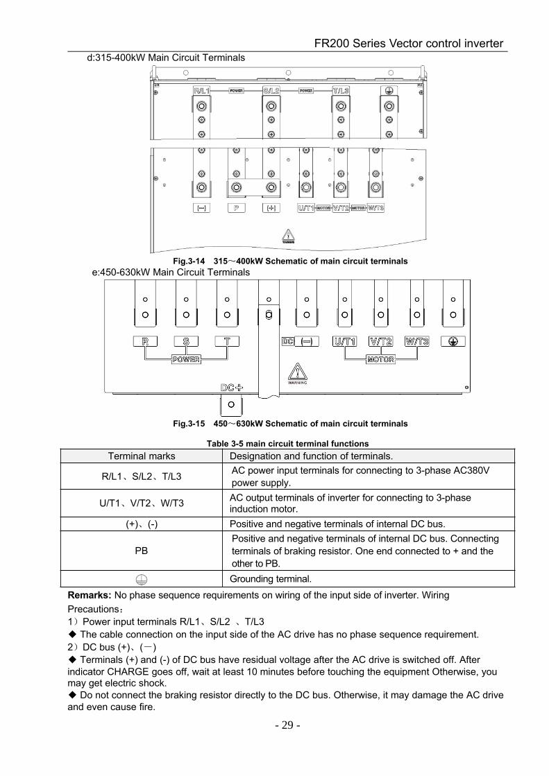
d:315-400kW Main Circuit Terminals
Fig.3-14 315~400kW Schematic of main circuit terminalse:450-630kW Main Circuit Terminals
Fig.3-15 450~630kW Schematic of main circuit terminals
Table 3-5 main circuit terminal functionsTerminal marks Designation and function of terminals.
R/L1、S/L2、T/L3 AC power input terminals for connecting to 3-phase AC380Vpower supply.
U/T1、V/T2、W/T3 AC output terminals of inverter for connecting to 3-phaseinduction motor.
(+)、(-) Positive and negative terminals of internal DC bus.
PBPositive and negative terminals of internal DC bus. Connectingterminals of braking resistor. One end connected to + and theother to PB.Grounding terminal.
Remarks: No phase sequence requirements on wiring of the input side of inverter. WiringPrecautions:1)Power input terminals R/L1、S/L2 、T/L3 The cable connection on the input side of the AC drive has no phase sequence requirement.2)DC bus (+)、(-) Terminals (+) and (-) of DC bus have residual voltage after the AC drive is switched off. Afterindicator CHARGE goes off, wait at least 10 minutes before touching the equipment Otherwise, youmay get electric shock. Do not connect the braking resistor directly to the DC bus. Otherwise, it may damage the AC driveand even cause fire.
FR200 Series Vector control inverter
- 30 -
3)Braking resistor connection terminals (+)、PB The cable length of the braking resistor shall be less than 5 m. Otherwise, it may damage the ACdrive.4)AC drive output terminals U/T1、V/T2、W/T3 The capacitor or surge absorber cannot be connected to the output side of the AC drive. Otherwise,it may cause frequent AC drive fault or even damage the AC drive.
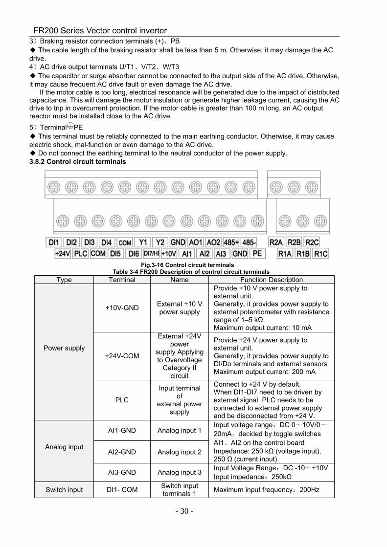
If the motor cable is too long, electrical resonance will be generated due to the impact of distributedcapacitance. This will damage the motor insulation or generate higher leakage current, causing the ACdrive to trip in overcurrent protection. If the motor cable is greater than 100 m long, an AC outputreactor must be installed close to the AC drive.5)Terminal PE This terminal must be reliably connected to the main earthing conductor. Otherwise, it may causeelectric shock, mal-function or even damage to the AC drive. Do not connect the earthing terminal to the neutral conductor of the power supply.3.8.2 Control circuit terminals
Fig.3-16 Control circuit terminalsTable 3-4 FR200 Description of control circuit terminals
Type Terminal Name Function Description
Power supply
+10V-GND External +10 Vpower supply
Provide +10 V power supply toexternal unit.Generally, it provides power supply toexternal potentiometer with resistancerange of 1–5 kΩ.Maximum output current: 10 mA
+24V-COM
External +24Vpower
supply Applyingto Overvoltage
Category IIcircuit
Provide +24 V power supply toexternal unit.Generally, it provides power supply toDI/Do terminals and external sensors.Maximum output current: 200 mA
PLC
Input terminalof
external powersupply
Connect to +24 V by default.When DI1-DI7 need to be driven byexternal signal, PLC needs to beconnected to external power supplyand be disconnected from +24 V.
Analog input
AI1-GND Analog input 1Input voltage range:DC 0~10V/0~20mA,decided by toggle switchesAI1、AI2 on the control boardImpedance: 250 kΩ (voltage input),250 Ω (current input)
AI2-GND Analog input 2
AI3-GND Analog input 3 Input Voltage Range:DC -10~+10VInput impedance:250kΩ
Switch input DI1- COM Switch inputterminals 1 Maximum input frequency:200Hz
FR200 Series Vector control inverter
- 31 -
Impedance:2.4kΩVoltage range for level input:9V~30V
DI2- COM Switch inputterminals 2
DI3- COM Switch inputterminals 3
DI4- COM Switch inputterminals 4
DI5- COM Switch inputterminals 5
DI6- COM Switch inputterminals 6
DI7/HI-COM
Switch inputterminals 7 OR
High-speedpulse input
Besides features of DI1–DI6, it can beused for high-speed pulse input.Maximum input frequency: 100 kHz
Analogoutput
AO1-GND Analog outputterminal 1
Output voltage range:DC 0~10V/0~20mA,decided by toggle switchesAO1、AO2 on the control boardImpedance requirements≥10kΩAO2-GND Analog output
terminal 2
Switch output
Y1-COM Open collectoroutput 1
Voltage range:0~24VCurrent range:0~50mA
Y2/HO-COM
Open collectoroutput 2 ORHigh-speedpulse output
Besides features of Y1, it can be usedfor High-speed pulse output channels.The maximum out put frequency:100kHz
Relay output
R1A-R1C Normally openterminal
Contact driving capacity:AC250V,3A,COSØ=0.4.DC 30V,1A
R1B-R1C Normallyclosed terminal
R2A-R2C Normally openterminal
R2B-R2C Normallyclosed terminal
485Communication
485+-485-485
CommunicationTerminals
Rate:4800/9600/19200/38400/57600/115200bpsTermination resistor is set by thetoggle switch on the control panelRS485
GND
485Communication
shieldedground
Shield PE Shield Ground Ground terminal for shield
AuxiliaryInterface
Externaloperation
panel interface
Use standard network cableMaximum cable distance: 50m
UP/DOWNLOAD Parametercopy interface
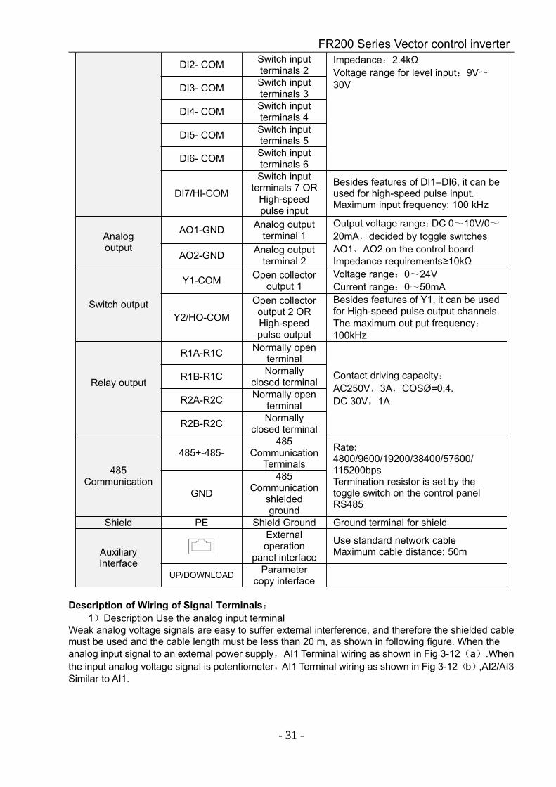
Description of Wiring of Signal Terminals:1)Description Use the analog input terminal
Weak analog voltage signals are easy to suffer external interference, and therefore the shielded cablemust be used and the cable length must be less than 20 m, as shown in following figure. When theanalog input signal to an external power supply,AI1 Terminal wiring as shown in Fig 3-12(a).Whenthe input analog voltage signal is potentiometer,AI1 Terminal wiring as shown in Fig 3-12(b),AI2/AI3Similar to AI1.
FR200 Series Vector control inverter
- 32 -
(a) (b)Fig.3-17 Analog input terminal wiring diagram
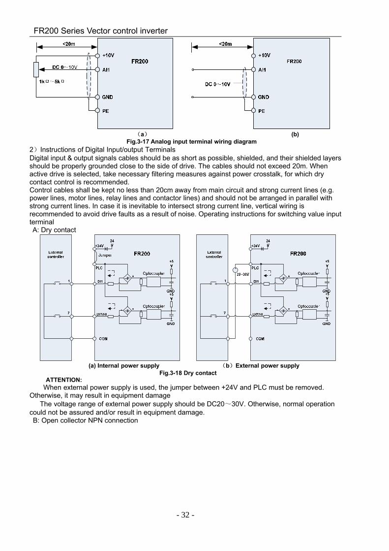
2)Instructions of Digital Input/output TerminalsDigital input & output signals cables should be as short as possible, shielded, and their shielded layersshould be properly grounded close to the side of drive. The cables should not exceed 20m. Whenactive drive is selected, take necessary filtering measures against power crosstalk, for which drycontact control is recommended.Control cables shall be kept no less than 20cm away from main circuit and strong current lines (e.g.power lines, motor lines, relay lines and contactor lines) and should not be arranged in parallel withstrong current lines. In case it is inevitable to intersect strong current line, vertical wiring isrecommended to avoid drive faults as a result of noise. Operating instructions for switching value inputterminalA: Dry contact
(a) Internal power supply (b)External power supplyFig.3-18 Dry contact
ATTENTION:When external power supply is used, the jumper between +24V and PLC must be removed.
Otherwise, it may result in equipment damageThe voltage range of external power supply should be DC20~30V. Otherwise, normal operation
could not be assured and/or result in equipment damage.B: Open collector NPN connection
FR200 Series Vector control inverter
- 33 -
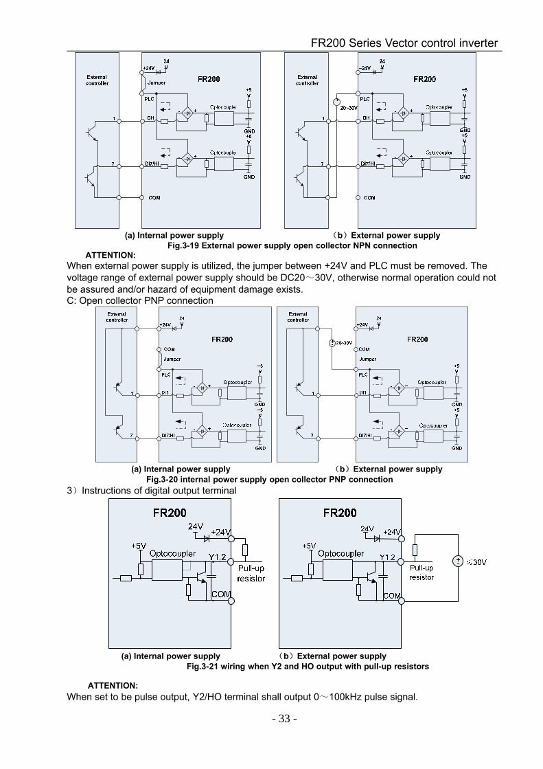
(a) Internal power supply (b)External power supplyFig.3-19 External power supply open collector NPN connection
ATTENTION:When external power supply is utilized, the jumper between +24V and PLC must be removed. Thevoltage range of external power supply should be DC20~30V, otherwise normal operation could notbe assured and/or hazard of equipment damage exists.C: Open collector PNP connection
(a) Internal power supply (b)External power supplyFig.3-20 internal power supply open collector PNP connection
3)Instructions of digital output terminal
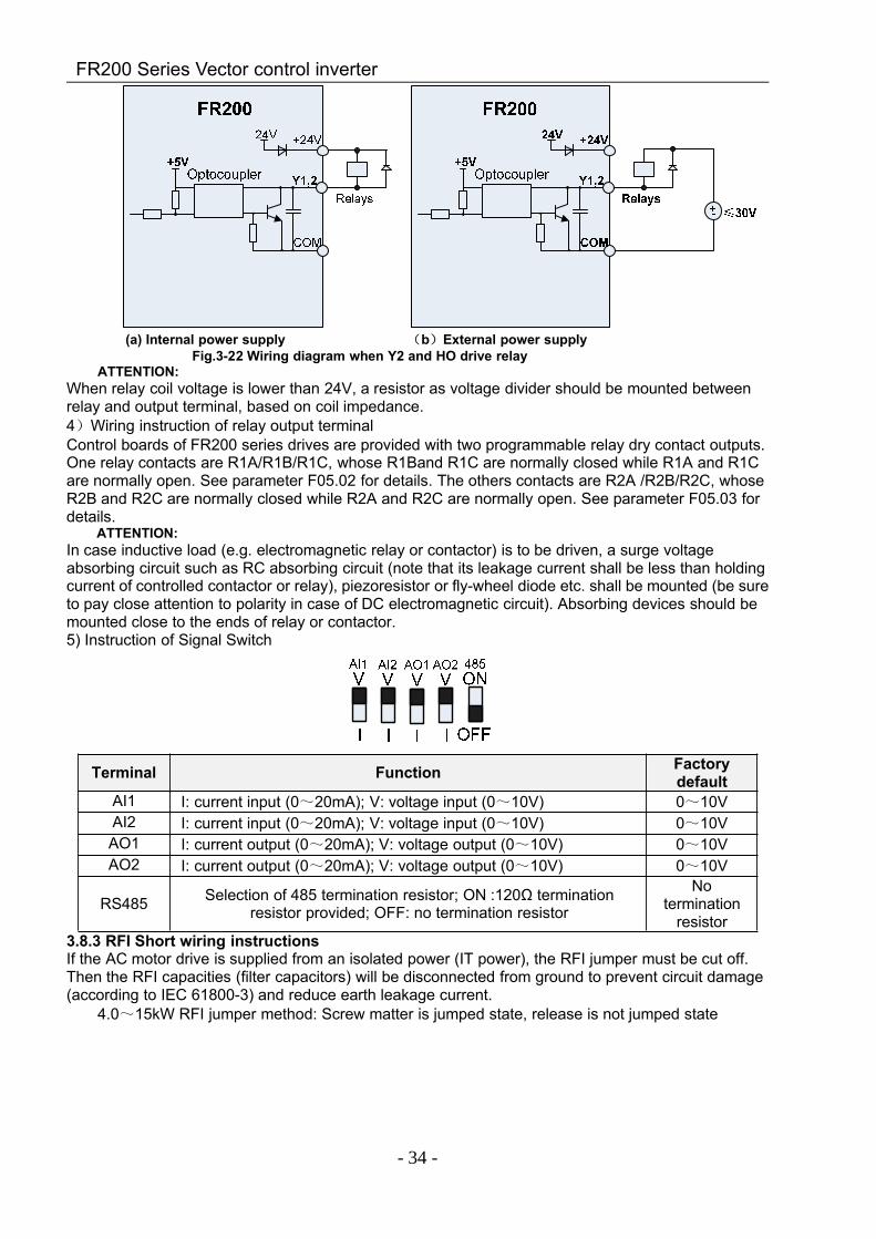
(a) Internal power supply (b)External power supplyFig.3-21 wiring when Y2 and HO output with pull-up resistors
ATTENTION:When set to be pulse output, Y2/HO terminal shall output 0~100kHz pulse signal.
FR200 Series Vector control inverter
- 34 -
(a) Internal power supply (b)External power supplyFig.3-22 Wiring diagram when Y2 and HO drive relay
ATTENTION:When relay coil voltage is lower than 24V, a resistor as voltage divider should be mounted betweenrelay and output terminal, based on coil impedance.4)Wiring instruction of relay output terminalControl boards of FR200 series drives are provided with two programmable relay dry contact outputs.One relay contacts are R1A/R1B/R1C, whose R1Band R1C are normally closed while R1A and R1Care normally open. See parameter F05.02 for details. The others contacts are R2A /R2B/R2C, whoseR2B and R2C are normally closed while R2A and R2C are normally open. See parameter F05.03 fordetails.
ATTENTION:In case inductive load (e.g. electromagnetic relay or contactor) is to be driven, a surge voltageabsorbing circuit such as RC absorbing circuit (note that its leakage current shall be less than holdingcurrent of controlled contactor or relay), piezoresistor or fly-wheel diode etc. shall be mounted (be sureto pay close attention to polarity in case of DC electromagnetic circuit). Absorbing devices should bemounted close to the ends of relay or contactor.5) Instruction of Signal Switch
Terminal Function Factorydefault
AI1 I: current input (0~20mA); V: voltage input (0~10V) 0~10VAI2 I: current input (0~20mA); V: voltage input (0~10V) 0~10VAO1 I: current output (0~20mA); V: voltage output (0~10V) 0~10VAO2 I: current output (0~20mA); V: voltage output (0~10V) 0~10V
RS485 Selection of 485 termination resistor; ON :120Ω terminationresistor provided; OFF: no termination resistor
Notermination
resistor3.8.3 RFI Short wiring instructionsIf the AC motor drive is supplied from an isolated power (IT power), the RFI jumper must be cut off.Then the RFI capacities (filter capacitors) will be disconnected from ground to prevent circuit damage(according to IEC 61800-3) and reduce earth leakage current.
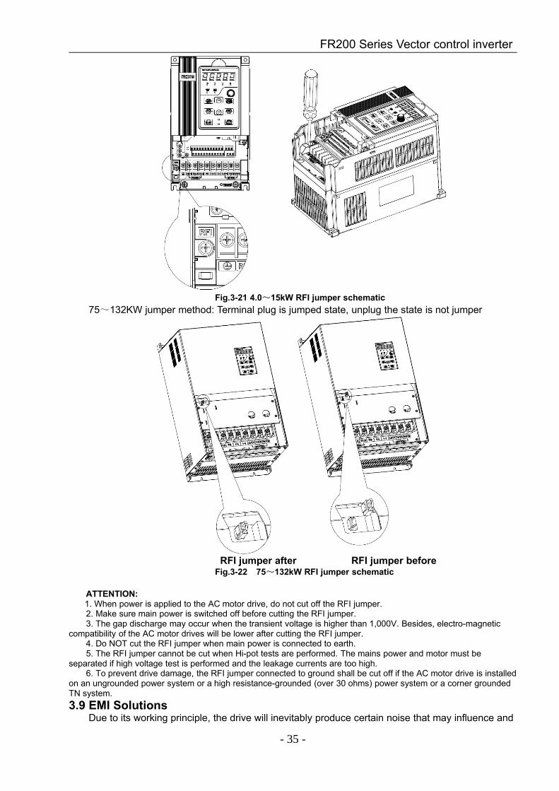
4.0~15kW RFI jumper method: Screw matter is jumped state, release is not jumped state
FR200 Series Vector control inverter
- 35 -
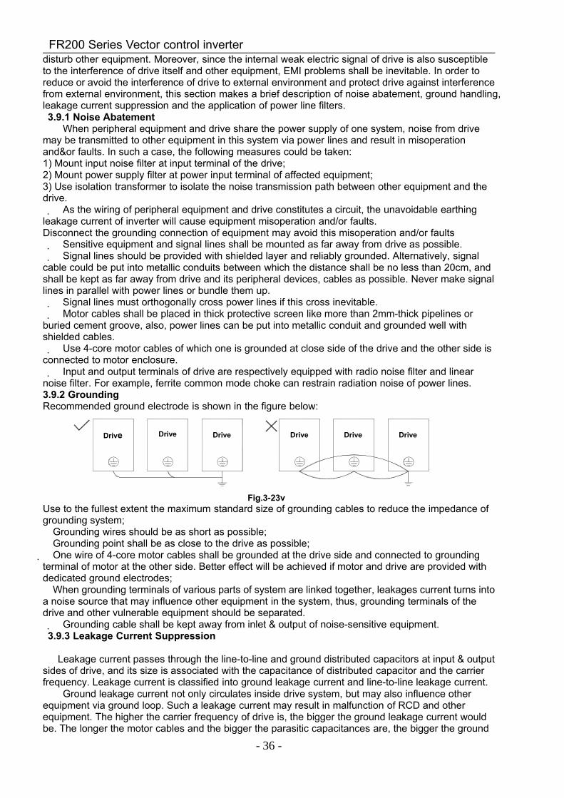
Fig.3-21 4.0~15kW RFI jumper schematic75~132KW jumper method: Terminal plug is jumped state, unplug the state is not jumper
RFI jumper after RFI jumper beforeFig.3-22 75~132kW RFI jumper schematic
ATTENTION:1. When power is applied to the AC motor drive, do not cut off the RFI jumper.2. Make sure main power is switched off before cutting the RFI jumper.3. The gap discharge may occur when the transient voltage is higher than 1,000V. Besides, electro-magnetic
compatibility of the AC motor drives will be lower after cutting the RFI jumper.4. Do NOT cut the RFI jumper when main power is connected to earth.5. The RFI jumper cannot be cut when Hi-pot tests are performed. The mains power and motor must be
separated if high voltage test is performed and the leakage currents are too high.6. To prevent drive damage, the RFI jumper connected to ground shall be cut off if the AC motor drive is installed
on an ungrounded power system or a high resistance-grounded (over 30 ohms) power system or a corner groundedTN system.3.9 EMI Solutions
Due to its working principle, the drive will inevitably produce certain noise that may influence and
FR200 Series Vector control inverter
- 36 -
disturb other equipment. Moreover, since the internal weak electric signal of drive is also susceptibleto the interference of drive itself and other equipment, EMI problems shall be inevitable. In order toreduce or avoid the interference of drive to external environment and protect drive against interferencefrom external environment, this section makes a brief description of noise abatement, ground handling,leakage current suppression and the application of power line filters.3.9.1 Noise Abatement
When peripheral equipment and drive share the power supply of one system, noise from drivemay be transmitted to other equipment in this system via power lines and result in misoperationand&or faults. In such a case, the following measures could be taken:1) Mount input noise filter at input terminal of the drive;2) Mount power supply filter at power input terminal of affected equipment;3) Use isolation transformer to isolate the noise transmission path between other equipment and thedrive. As the wiring of peripheral equipment and drive constitutes a circuit, the unavoidable earthing
leakage current of inverter will cause equipment misoperation and/or faults.Disconnect the grounding connection of equipment may avoid this misoperation and/or faults Sensitive equipment and signal lines shall be mounted as far away from drive as possible. Signal lines should be provided with shielded layer and reliably grounded. Alternatively, signal
cable could be put into metallic conduits between which the distance shall be no less than 20cm, andshall be kept as far away from drive and its peripheral devices, cables as possible. Never make signallines in parallel with power lines or bundle them up. Signal lines must orthogonally cross power lines if this cross inevitable. Motor cables shall be placed in thick protective screen like more than 2mm-thick pipelines or
buried cement groove, also, power lines can be put into metallic conduit and grounded well withshielded cables. Use 4-core motor cables of which one is grounded at close side of the drive and the other side is
connected to motor enclosure. Input and output terminals of drive are respectively equipped with radio noise filter and linear
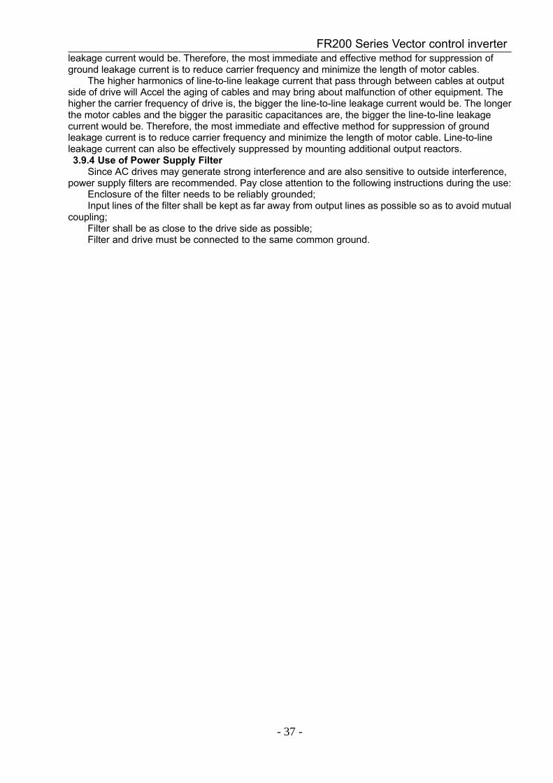
noise filter. For example, ferrite common mode choke can restrain radiation noise of power lines.3.9.2 GroundingRecommended ground electrode is shown in the figure below:
变频器 变频器 变频器 变频器 变频器 变频器
Fig.3-23vUse to the fullest extent the maximum standard size of grounding cables to reduce the impedance ofgrounding system;
Grounding wires should be as short as possible;Grounding point shall be as close to the drive as possible;
One wire of 4-core motor cables shall be grounded at the drive side and connected to groundingterminal of motor at the other side. Better effect will be achieved if motor and drive are provided withdedicated ground electrodes;
When grounding terminals of various parts of system are linked together, leakages current turns intoa noise source that may influence other equipment in the system, thus, grounding terminals of thedrive and other vulnerable equipment should be separated. Grounding cable shall be kept away from inlet & output of noise-sensitive equipment.3.9.3 Leakage Current Suppression
Leakage current passes through the line-to-line and ground distributed capacitors at input & outputsides of drive, and its size is associated with the capacitance of distributed capacitor and the carrierfrequency. Leakage current is classified into ground leakage current and line-to-line leakage current.
Ground leakage current not only circulates inside drive system, but may also influence otherequipment via ground loop. Such a leakage current may result in malfunction of RCD and otherequipment. The higher the carrier frequency of drive is, the bigger the ground leakage current wouldbe. The longer the motor cables and the bigger the parasitic capacitances are, the bigger the ground
Drive Drive Drive Drive Drive Drive
FR200 Series Vector control inverter
- 37 -
leakage current would be. Therefore, the most immediate and effective method for suppression ofground leakage current is to reduce carrier frequency and minimize the length of motor cables.
The higher harmonics of line-to-line leakage current that pass through between cables at outputside of drive will Accel the aging of cables and may bring about malfunction of other equipment. Thehigher the carrier frequency of drive is, the bigger the line-to-line leakage current would be. The longerthe motor cables and the bigger the parasitic capacitances are, the bigger the line-to-line leakagecurrent would be. Therefore, the most immediate and effective method for suppression of groundleakage current is to reduce carrier frequency and minimize the length of motor cable. Line-to-lineleakage current can also be effectively suppressed by mounting additional output reactors.3.9.4 Use of Power Supply Filter
Since AC drives may generate strong interference and are also sensitive to outside interference,power supply filters are recommended. Pay close attention to the following instructions during the use:
Enclosure of the filter needs to be reliably grounded;Input lines of the filter shall be kept as far away from output lines as possible so as to avoid mutual
coupling;Filter shall be as close to the drive side as possible;Filter and drive must be connected to the same common ground.
FR200 Series Vector control inverter
- 38 -
Chapter 4 Operation and display
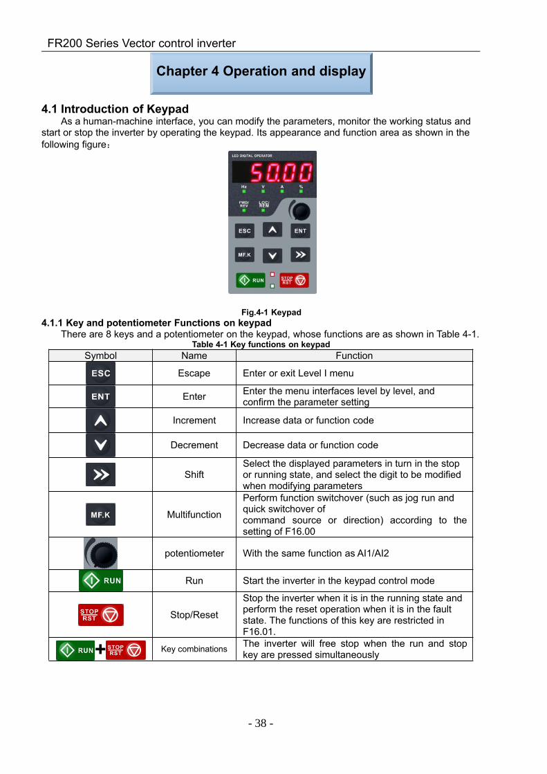
4.1 Introduction of KeypadAs a human-machine interface, you can modify the parameters, monitor the working status and
start or stop the inverter by operating the keypad. Its appearance and function area as shown in thefollowing figure:
Fig.4-1 Keypad4.1.1 Key and potentiometer Functions on keypad
There are 8 keys and a potentiometer on the keypad, whose functions are as shown in Table 4-1.Table 4-1 Key functions on keypad
Symbol Name Function
Escape Enter or exit Level I menu
Enter Enter the menu interfaces level by level, andconfirm the parameter setting
Increment Increase data or function code
Decrement Decrease data or function code
ShiftSelect the displayed parameters in turn in the stopor running state, and select the digit to be modifiedwhen modifying parameters
Multifunction
Perform function switchover (such as jog run andquick switchover ofcommand source or direction) according to thesetting of F16.00
potentiometer With the same function as AI1/AI2
Run Start the inverter in the keypad control mode
Stop/Reset
Stop the inverter when it is in the running state andperform the reset operation when it is in the faultstate. The functions of this key are restricted inF16.01.
+ Key combinations The inverter will free stop when the run and stopkey are pressed simultaneously
FR200 Series Vector control inverter
- 39 -
4.1.2 Keypad IndicatorsThere are 8 Indicators on the keypad, whose descriptions are as shown in Table 4-2.
Table 4-2 Description of indicatorsIndicator Name Meaning
Unit
Hz Frequency ON: currently displayed parameter isfrequency
V Voltage ON:currently displayed parameter is voltageA Current ON:currently displayed parameter is current
% Percentage ON:currently displayed parameter ispercentage
All off Other unit Other unit or no unit
State
FWD/REV Forward orreverse
ON:the drive is running reverseOFF:the drive is running forwardFlash:dormant state
LOC/REMKeypad,
terminals orcommunication
ON:Terminal controlOFF:Keypad controlFlash:Communication control
(Green border)Running state
ON:Running stateOFF:Stopped stateFlash:In process of stop
(Red border)Fault state
ON:Fault stateOFF:Normal stateFlash:Warning state
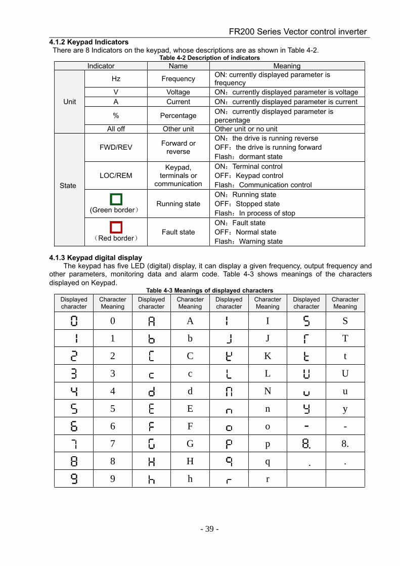
4.1.3 Keypad digital displayThe keypad has five LED (digital) display, it can display a given frequency, output frequency and
other parameters, monitoring data and alarm code. Table 4-3 shows meanings of the charactersdisplayed on Keypad.
Table 4-3 Meanings of displayed charactersDisplayedcharacter
CharacterMeaning
Displayedcharacter
CharacterMeaning
Displayedcharacter
CharacterMeaning
Displayedcharacter
CharacterMeaning
0 A I S
1 b J T
2 C K t
3 c L U
4 d N u
5 E n y
6 F o -
7 G p 8.
8 H q .
9 h r
FR200 Series Vector control inverter
- 40 -
4.1.4 Message statusA message appears when the state of completion of certain operations. Prompt message
characters and their meanings are specified in Table 4-4.Table 4-4 Prompt characters
Prompt symbol Meaning Prompt symbol Meaning
Err00~Err99 Fault type TUNEMotor parameteridentification in
processA00~A99 Alarm type -END- Write parameter
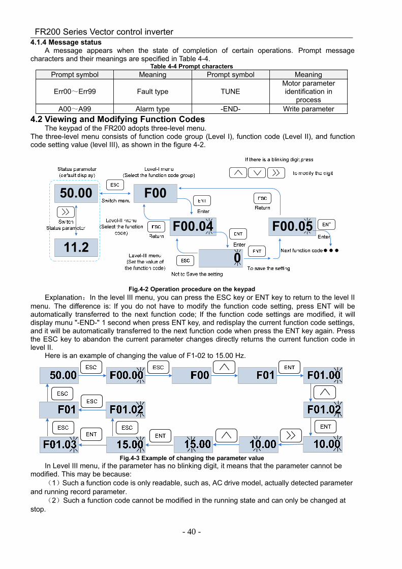
4.2 Viewing and Modifying Function CodesThe keypad of the FR200 adopts three-level menu.
The three-level menu consists of function code group (Level I), function code (Level II), and functioncode setting value (level III), as shown in the figure 4-2.
Fig.4-2 Operation procedure on the keypadExplanation:In the level III menu, you can press the ESC key or ENT key to return to the level II
menu. The difference is: If you do not have to modify the function code setting, press ENT will beautomatically transferred to the next function code; If the function code settings are modified, it willdisplay munu "-END-" 1 second when press ENT key, and redisplay the current function code settings,and it will be automatically transferred to the next function code when press the ENT key again. Pressthe ESC key to abandon the current parameter changes directly returns the current function code inlevel II.
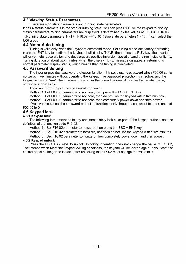
Here is an example of changing the value of F1-02 to 15.00 Hz.
Fig.4-3 Example of changing the parameter valueIn Level III menu, if the parameter has no blinking digit, it means that the parameter cannot be
modified. This may be because:(1)Such a function code is only readable, such as, AC drive model, actually detected parameter
and running record parameter.(2)Such a function code cannot be modified in the running state and can only be changed at
stop.
FR200 Series Vector control inverter
- 41 -
4.3 Viewing Status ParametersThere are stop state parameters and running state parameters.
It has 4 status parameters in the stop or running state .You can press “>>” on the keypad to displaystatus parameters. Which parameters are displayed is determined by the values of F16.03~F16.06(Running state parameters 1~4)、F16.07~F16.10(stop state parameters1~4),it can select theU00 group.4.4 Motor Auto-tuning
Tuning is valid only when the keyboard command mode. Set tuning mode (stationary or rotating),press the ENT key to confirm, the keyboard will display TUNE, then press the RUN key, the inverterwill drive motor acceleration and deceleration, positive inversion operation,and the run indicator lights.Tuning duration of about two minutes, when the display TUNE message disappears, returning tonormal parameter display status, which means that the tuning is completed.4.5 Password Setting
The inverter provides password protection function, it is set a user's password when F00.00 set tononzero.If five minutes without operating the keypad, the password protection is effective, and thekeypad will show “-----”, then the user must enter the correct password to enter the regular menu,otherwise inaccessible.
There are three ways a user password into force:Method 1: Set F00.00 parameter to nonzero, then press the ESC + ENT key.Method 2: Set F00.00 parameter to nonzero, then do not use the keypad within five minutes.Method 3: Set F00.00 parameter to nonzero, then completely power down and then power.If you want to cancel the password protection functions, only through a password to enter, and set
F00.00 to 0.4.6 Keypad lock4.6.1 Keypad lock
The following three methods to any one immediately lock all or part of the keypad buttons; see thedefinition of the function code F16.02.
Method 1:Set F16.02parameter to nonzero, then press the ESC + ENT key.Method 2:Set F16.02 parameter to nonzero, and then do not use the keypad within five minutes.Method 3:Set F16.02 parameter to nonzero, then completely power down and then power.
4.6.2 Keypad unlockPress the ESC + >> keys to unlock.Unlocking operation does not change the value of F16.02,
That means when Meet the keypad locking conditions, the keypad will be locked again. If you want thecontrol panel no longer be locked, after unlocking the F16.02 must change the value to 0.
FR200 Series Vector control inverter
- 42 -
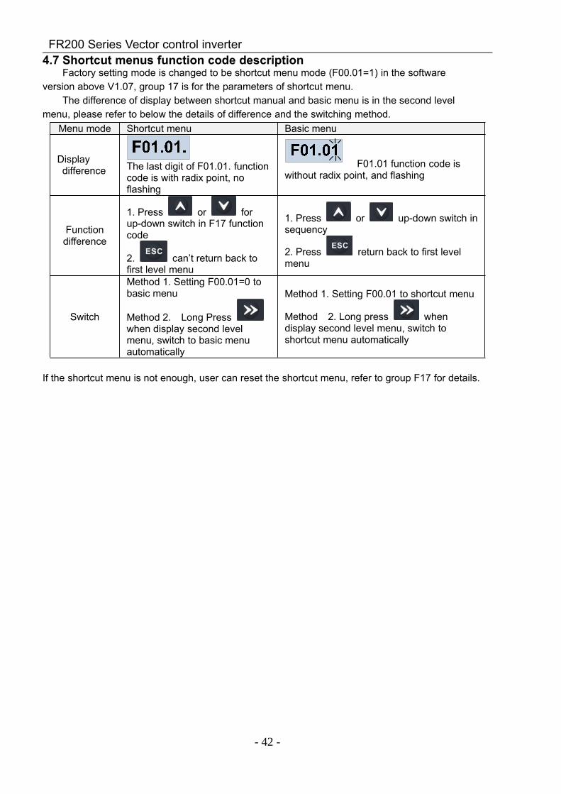
4.7 Shortcut menus function code descriptionFactory setting mode is changed to be shortcut menu mode (F00.01=1) in the software
version above V1.07, group 17 is for the parameters of shortcut menu.The difference of display between shortcut manual and basic menu is in the second level
menu, please refer to below the details of difference and the switching method.Menu mode Shortcut menu Basic menu
Displaydifference The last digit of F01.01. function
code is with radix point, noflashing
F01.01 function code iswithout radix point, and flashing
Functiondifference
1. Press or forup-down switch in F17 functioncode
2. can’t return back tofirst level menu
1. Press or up-down switch insequency
2. Press return back to first levelmenu
Switch
Method 1. Setting F00.01=0 tobasic menu
Method 2. Long Presswhen display second levelmenu, switch to basic menuautomatically
Method 1. Setting F00.01 to shortcut menu
Method 2. Long press whendisplay second level menu, switch toshortcut menu automatically
If the shortcut menu is not enough, user can reset the shortcut menu, refer to group F17 for details.
FR200 Series Vector control inverter
- 43 -
Chapter 5 List of Parameter
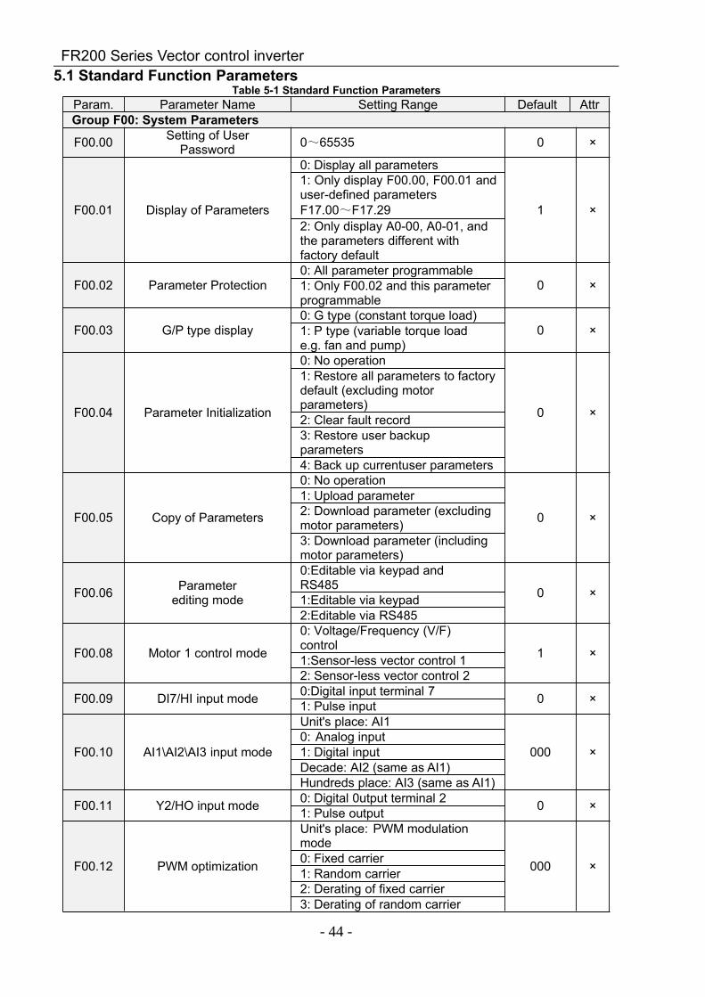
Group F00~F17 are standard function parameters. Group U00 is status monitoring parameters.Group U01 is fault record parameters.
The symbols in the function code table are described as follows:" " means the value of this parameter can be modified in stop and running status of drive;"×" means the value of this parameter cannot be modified when drive is running;"⊙" means this parameter is a measured value that cannot be modified;Default: The value when restored to factory default. Neither measured parameter value nor
recorded value will be restored.Setting Range: the scope of setting and display of parametersFR200 parameter groups are listed below:
Category Parameter GroupSystem Parameters F00: System Parameters
Basic Parameters
F01: Frequency Command
F02: Start/Stop Control Start/Stop Control
F03: Accelerate/Decelerate Parameters
Input & Output Terminals
F04: Digital InputF05: Digital OutputF06: Analog and Pulse InputF07: Analog and Pulse Output
Motor and Control ParametersF08: Parameters of Motor 1F09: V/f Control Parameters of Motor 1F10: Vector Control Parameters of Motor 1
Protection Parameters F11: Protection Parameters
Application Parameters
F12: Multi-Reference and Simple PLC FunctionF13: Process PIDF14: Swing Frequency, Fixed Length , Count andWakeup
Communication Parameters F15: Communication ParametersKeys and Display of KeypadParameters F16:Keys and Display of Keypad Parameters
User-defined Display Parameters F17:User-defined Display Parameters
Monitoring ParametersU00:Status monitoringU01:Fault record
FR200 Series Vector control inverter
- 44 -
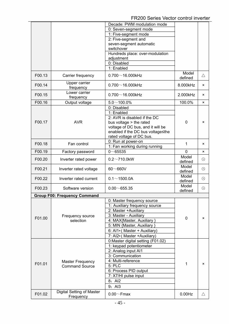
5.1 Standard Function ParametersTable 5-1 Standard Function Parameters
Param. Parameter Name Setting Range Default AttrGroup F00: System Parameters
F00.00 Setting of UserPassword 0~65535 0 ×
F00.01 Display of Parameters
0: Display all parameters
1 ×
1: Only display F00.00, F00.01 anduser-defined parametersF17.00~F17.292: Only display A0-00, A0-01, andthe parameters different withfactory default
F00.02 Parameter Protection0: All parameter programmable
0 ×1: Only F00.02 and this parameterprogrammable
F00.03 G/P type display0: G type (constant torque load)
0 ×1: P type (variable torque loade.g. fan and pump)
F00.04 Parameter Initialization
0: No operation
0 ×
1: Restore all parameters to factorydefault (excluding motorparameters)2: Clear fault record3: Restore user backupparameters4: Back up currentuser parameters
F00.05 Copy of Parameters
0: No operation
0 ×
1: Upload parameter2: Download parameter (excludingmotor parameters)3: Download parameter (includingmotor parameters)
F00.06 Parameterediting mode
0:Editable via keypad andRS485 0 ×1:Editable via keypad2:Editable via RS485
F00.08 Motor 1 control mode
0: Voltage/Frequency (V/F)control 1 ×1:Sensor-less vector control 12: Sensor-less vector control 2
F00.09 DI7/HI input mode 0:Digital input terminal 7 0 ×1: Pulse input
F00.10 AI1\AI2\AI3 input mode
Unit's place: AI1
000 ×0: Analog input1: Digital inputDecade: AI2 (same as AI1)Hundreds place: AI3 (same as AI1)
F00.11 Y2/HO input mode 0: Digital 0utput terminal 2 0 ×1: Pulse output
F00.12 PWM optimization
Unit's place: PWM modulationmode
000 ×0: Fixed carrier1: Random carrier2: Derating of fixed carrier3: Derating of random carrier
FR200 Series Vector control inverter
- 45 -
Decade: PWM modulation mode0: Seven-segment mode1: Five-segment mode2: Five-segment andseven-segment automaticswitchoverHundreds place: over-modulationadjustment0: Disabled1: Enabled
F00.13 Carrier frequency 0.700~16.000kHz Modeldefined
F00.14 Upper carrierfrequency 0.700~16.000kHz 8.000kHz ×
F00.15 Lower carrierfrequency 0.700~16.000kHz 2.000kHz ×
F00.16 Output voltage 5.0~100.0% 100.0% ×
F00.17 AVR
0: Disabled
0 ×
1: Enabled2: AVR is disabled if the DCbus voltage > the ratedvoltage of DC bus, and it will beenabled if the DC bus voltage≤therated voltage of DC bus.
F00.18 Fan control 0: Run at power-on 1 ×1: Fan working during runningF00.19 Factory password 0~65535 0 ×
F00.20 Inverter rated power 0.2~710.0kW Modeldefined ⊙
F00.21 Inverter rated voltage 60~660V Modeldefined ⊙
F00.22 Inverter rated current 0.1~1500.0A Modeldefined ⊙
F00.23 Software version 0.00~655.35 Modeldefined ⊙
Group F00: Frequency Command
F01.00 Frequency sourceselection
0: Master frequency source
0 ×
1: Auxiliary frequency source2: Master +Auxiliary3: Master - Auxiliary4: MAXMaster, Auxiliary 5: MIN Master, Auxiliary 6: AI1∗( Master + Auxiliary)7: AI2∗( Master +Auxiliary)
F01.01 Master FrequencyCommand Source
0:Master digital setting (F01.02)
1 ×
1: keypad potentiometer2: Analog input AI13: Communication4: Multi-reference5: PLC6: Process PID output7: X7/HI pulse input8:AI29:AI3
F01.02 Digital Setting of MasterFrequency 0.00~Fmax 0.00Hz
FR200 Series Vector control inverter
- 46 -
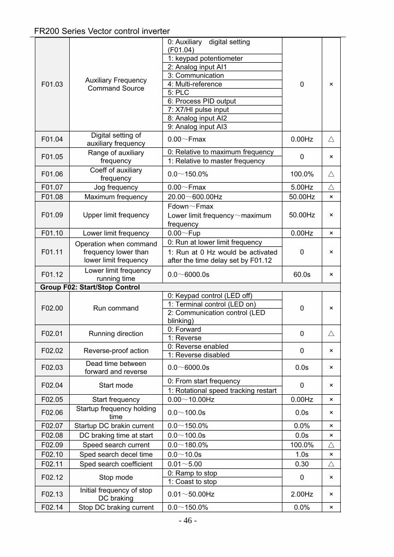
F01.03 Auxiliary FrequencyCommand Source
0: Auxiliary digital setting(F01.04)
0 ×
1: keypad potentiometer2: Analog input AI13: Communication4: Multi-reference5: PLC6: Process PID output7: X7/HI pulse input8: Analog input AI29: Analog input AI3
F01.04 Digital setting ofauxiliary frequency 0.00~Fmax 0.00Hz
F01.05 Range of auxiliaryfrequency
0: Relative to maximum frequency0 ×1: Relative to master frequency
F01.06 Coeff of auxiliaryfrequency 0.0~150.0% 100.0%
F01.07 Jog frequency 0.00~Fmax 5.00Hz
F01.08 Maximum frequency 20.00~600.00Hz 50.00Hz ×
F01.09 Upper limit frequencyFdown~FmaxLower limit frequency~maximumfrequency
50.00Hz ×
F01.10 Lower limit frequency 0.00~Fup 0.00Hz ×
F01.11Operation when command
frequency lower thanlower limit frequency
0: Run at lower limit frequency0 ×1: Run at 0 Hz would be activated
after the time delay set by F01.12
F01.12 Lower limit frequencyrunning time 0.0~6000.0s 60.0s ×
Group F02: Start/Stop Control
F02.00 Run command
0: Keypad control (LED off)
0 ×1: Terminal control (LED on)2: Communication control (LEDblinking)
F02.01 Running direction 0: Forward 0 1: Reverse
F02.02 Reverse-proof action 0: Reverse enabled 0 ×1: Reverse disabled
F02.03 Dead time betweenforward and reverse 0.0~6000.0s 0.0s ×
F02.04 Start mode 0: From start frequency 0 ×1: Rotational speed tracking restart
F02.05 Start frequency 0.00~10.00Hz 0.00Hz ×
F02.06 Startup frequency holdingtime 0.0~100.0s 0.0s ×
F02.07 Startup DC brakin current 0.0~150.0% 0.0% ×F02.08 DC braking time at start 0.0~100.0s 0.0s ×F02.09 Speed search current 0.0~180.0% 100.0%
F02.10 Sped search decel time 0.0~10.0s 1.0s ×F02.11 Sped search coefficient 0.01~5.00 0.30
F02.12 Stop mode 0: Ramp to stop 0 ×1: Coast to stop
F02.13 Initial frequency of stopDC braking 0.01~50.00Hz 2.00Hz ×
F02.14 Stop DC braking current 0.0~150.0% 0.0% ×
FR200 Series Vector control inverter
- 47 -
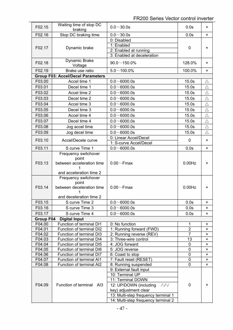
F02.15 Waiting time of stop DCbraking 0.0~30.0s 0.0s ×
F02.16 Stop DC braking time 0.0~30.0s 0.0s ×
F02.17 Dynamic brake
0: Disabled
0 ×1: Enabled2: Enabled at running3: Enabled at deceleration
F02.18 Dynamic BrakeVoltage 90.0~150.0% 128.0% ×
F02.19 Brake use ratio 5.0~100.0% 100.0% ×Group F03: Accel/Decel ParametersF03.00 Accel time 1 0.0~6000.0s 15.0s
F03.01 Decel time 1 0.0~6000.0s 15.0s
F03.02 Accel time 2 0.0~6000.0s 15.0s
F03.03 Decel time 2 0.0~6000.0s 15.0s
F03.04 Accel time 3 0.0~6000.0s 15.0s
F03.05 Decel time 3 0.0~6000.0s 15.0s
F03.06 Accel time 4 0.0~6000.0s 15.0s
F03.07 Decel time 4 0.0~6000.0s 15.0s
F03.08 Jog accel time 0.0~6000.0s 15.0s
F03.09 Jog decel time 0.0~6000.0s 15.0s
F03.10 Accel/Decele curve 0: Linear Accel/Decel 0 ×1: S-curve Accel/DecelF03.11 S curve Time 1 0.0~6000.0s 0.0s ×
F03.13
Frequency switchoverpoint
between acceleration time1
and acceleration time 2
0.00~Fmax 0.00Hz ×
F03.14
Frequency switchoverpoint
between deceleration time1
and deceleration time 2
0.00~Fmax 0.00Hz ×
F03.15 S curve Time 2 0.0~6000.0s 0.0s ×F03.16 S curve Time 3 0.0~6000.0s 0.0s ×F03.17 S curve Time 4 0.0~6000.0s 0.0s ×Group F04 Digital InputF04.00 Function of terminal DI1 0: No function 1 ×F04.01 Function of terminal DI2 1: Running forward (FWD) 2 ×F04.02 Function of terminal DI3 2: Running reverse (REV) 7 ×F04.03 Function of terminal DI4 3: Three-wire control 13 ×F04.04 Function of terminal DI5 4: JOG forward 0 ×F04.05 Function of terminal DI6 5: JOG reverse 0 ×F04.06 Function of terminal DI7 6: Coast to stop 0 ×F04.07 Function of terminal AI1 7: Fault reset (RESET) 0 ×F04.08 Function of terminal AI2 8: Running suspended 0 ×
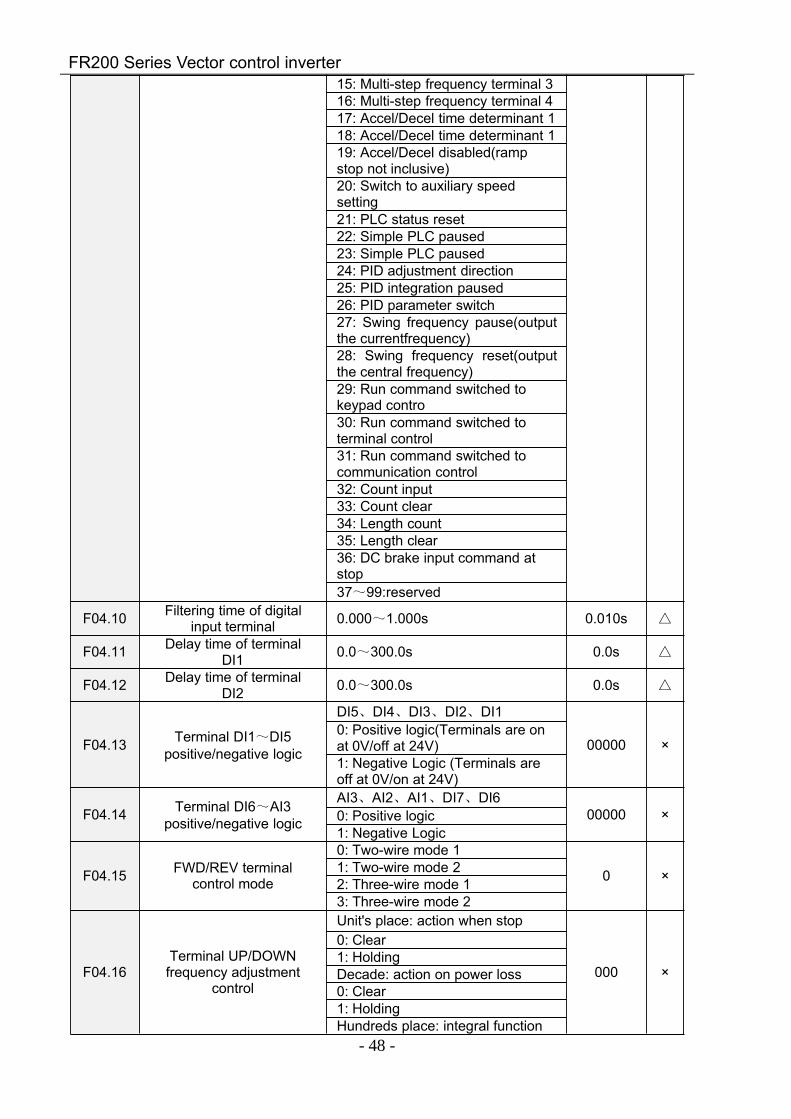
F04.09 Function of terminal AI3
9: External fault input
0 ×
10: Terminal UP11: Terminal DOWN12: UP/DOWN (including ∧/∨key) adjustment clear13: Multi-step frequency terminal 114: Multi-step frequency terminal 2
FR200 Series Vector control inverter
- 48 -
15: Multi-step frequency terminal 316: Multi-step frequency terminal 417: Accel/Decel time determinant 118: Accel/Decel time determinant 119: Accel/Decel disabled(rampstop not inclusive)20: Switch to auxiliary speedsetting21: PLC status reset22: Simple PLC paused23: Simple PLC paused24: PID adjustment direction25: PID integration paused26: PID parameter switch27: Swing frequency pause(outputthe currentfrequency)28: Swing frequency reset(outputthe central frequency)29: Run command switched tokeypad contro30: Run command switched toterminal control31: Run command switched tocommunication control32: Count input33: Count clear34: Length count35: Length clear36: DC brake input command atstop37~99:reserved
F04.10 Filtering time of digitalinput terminal 0.000~1.000s 0.010s
F04.11 Delay time of terminalDI1 0.0~300.0s 0.0s
F04.12 Delay time of terminalDI2 0.0~300.0s 0.0s
F04.13 Terminal DI1~DI5positive/negative logic
DI5、DI4、DI3、DI2、DI1
00000 ×0: Positive logic(Terminals are onat 0V/off at 24V)1: Negative Logic (Terminals areoff at 0V/on at 24V)
F04.14 Terminal DI6~AI3positive/negative logic
AI3、AI2、AI1、DI7、DI600000 ×0: Positive logic
1: Negative Logic
F04.15 FWD/REV terminalcontrol mode
0: Two-wire mode 1
0 ×1: Two-wire mode 22: Three-wire mode 13: Three-wire mode 2
F04.16Terminal UP/DOWNfrequency adjustment
control
Unit's place: action when stop
000 ×
0: Clear1: HoldingDecade: action on power loss0: Clear1: HoldingHundreds place: integral function
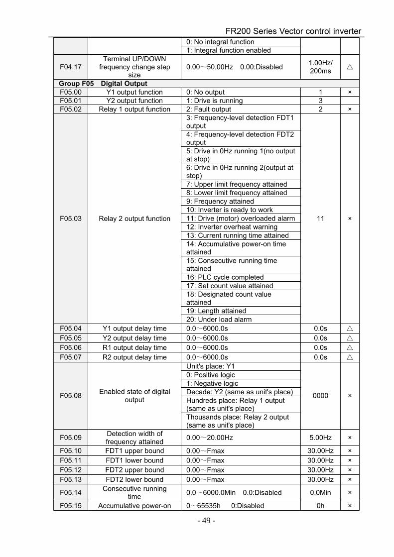
FR200 Series Vector control inverter
- 49 -
0: No integral function1: Integral function enabled
F04.17Terminal UP/DOWN
frequency change stepsize
0.00~50.00Hz 0.00:Disabled 1.00Hz/200ms
Group F05 Digital OutputF05.00 Y1 output function 0: No output 1 ×F05.01 Y2 output function 1: Drive is running 3F05.02 Relay 1 output function 2: Fault output 2 ×
F05.03 Relay 2 output function
3: Frequency-level detection FDT1output
11 ×
4: Frequency-level detection FDT2output5: Drive in 0Hz running 1(no outputat stop)6: Drive in 0Hz running 2(output atstop)7: Upper limit frequency attained8: Lower limit frequency attained9: Frequency attained10: Inverter is ready to work11: Drive (motor) overloaded alarm12: Inverter overheat warning13: Current running time attained14: Accumulative power-on timeattained15: Consecutive running timeattained16: PLC cycle completed17: Set count value attained18: Designated count valueattained19: Length attained20: Under load alarm
F05.04 Y1 output delay time 0.0~6000.0s 0.0s
F05.05 Y2 output delay time 0.0~6000.0s 0.0s
F05.06 R1 output delay time 0.0~6000.0s 0.0s
F05.07 R2 output delay time 0.0~6000.0s 0.0s
F05.08 Enabled state of digitaloutput
Unit's place: Y1
0000 ×
0: Positive logic1: Negative logicDecade: Y2 (same as unit's place)Hundreds place: Relay 1 output(same as unit's place)Thousands place: Relay 2 output(same as unit's place)
F05.09 Detection width offrequency attained 0.00~20.00Hz 5.00Hz ×
F05.10 FDT1 upper bound 0.00~Fmax 30.00Hz ×F05.11 FDT1 lower bound 0.00~Fmax 30.00Hz ×F05.12 FDT2 upper bound 0.00~Fmax 30.00Hz ×F05.13 FDT2 lower bound 0.00~Fmax 30.00Hz ×
F05.14 Consecutive runningtime 0.0~6000.0Min 0.0:Disabled 0.0Min ×
F05.15 Accumulative power-on 0~65535h 0:Disabled 0h ×
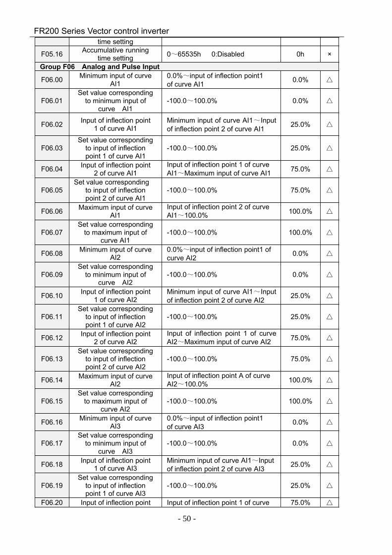
FR200 Series Vector control inverter
- 50 -
time setting
F05.16 Accumulative runningtime setting 0~65535h 0:Disabled 0h ×
Group F06 Analog and Pulse Input
F06.00 Minimum input of curveAI1
0.0%~input of inflection point1of curve AI1 0.0%
F06.01Set value corresponding
to minimum input ofcurve AI1
-100.0~100.0% 0.0%
F06.02 Input of inflection point1 of curve AI1
Minimum input of curve AI1~Inputof inflection point 2 of curve AI1 25.0%
F06.03Set value corresponding
to input of inflectionpoint 1 of curve AI1
-100.0~100.0% 25.0%
F06.04 Input of inflection point2 of curve AI1
Input of inflection point 1 of curveAI1~Maximum input of curve AI1 75.0%
F06.05Set value corresponding
to input of inflectionpoint 2 of curve AI1
-100.0~100.0% 75.0%
F06.06 Maximum input of curveAI1
Input of inflection point 2 of curveAI1~100.0% 100.0%
F06.07Set value corresponding
to maximum input ofcurve AI1
-100.0~100.0% 100.0%
F06.08 Minimum input of curveAI2
0.0%~input of inflection point1 ofcurve AI2 0.0%
F06.09Set value corresponding
to minimum input ofcurve AI2
-100.0~100.0% 0.0%
F06.10 Input of inflection point1 of curve AI2
Minimum input of curve AI1~Inputof inflection point 2 of curve AI2 25.0%
F06.11Set value corresponding
to input of inflectionpoint 1 of curve AI2
-100.0~100.0% 25.0%
F06.12 Input of inflection point2 of curve AI2
Input of inflection point 1 of curveAI2~Maximum input of curve AI2 75.0%
F06.13Set value corresponding
to input of inflectionpoint 2 of curve AI2
-100.0~100.0% 75.0%
F06.14 Maximum input of curveAI2
Input of inflection point A of curveAI2~100.0% 100.0%
F06.15Set value corresponding
to maximum input ofcurve AI2
-100.0~100.0% 100.0%
F06.16 Minimum input of curveAI3
0.0%~input of inflection point1of curve AI3 0.0%
F06.17Set value corresponding
to minimum input ofcurve AI3
-100.0~100.0% 0.0%
F06.18 Input of inflection point1 of curve AI3
Minimum input of curve AI1~Inputof inflection point 2 of curve AI3 25.0%
F06.19Set value corresponding
to input of inflectionpoint 1 of curve AI3
-100.0~100.0% 25.0%
F06.20 Input of inflection point Input of inflection point 1 of curve 75.0%
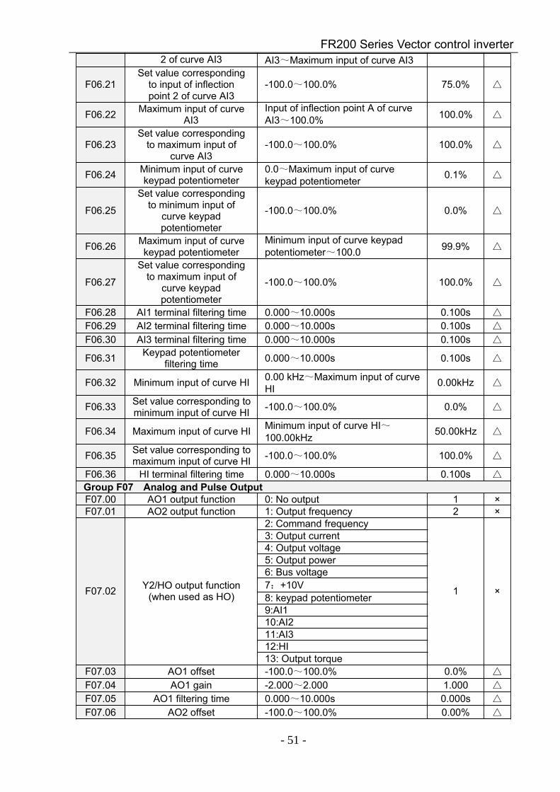
FR200 Series Vector control inverter
- 51 -
2 of curve AI3 AI3~Maximum input of curve AI3
F06.21Set value corresponding
to input of inflectionpoint 2 of curve AI3
-100.0~100.0% 75.0%
F06.22 Maximum input of curveAI3
Input of inflection point A of curveAI3~100.0% 100.0%
F06.23Set value corresponding
to maximum input ofcurve AI3
-100.0~100.0% 100.0%
F06.24 Minimum input of curvekeypad potentiometer
0.0~Maximum input of curvekeypad potentiometer 0.1%
F06.25
Set value correspondingto minimum input of
curve keypadpotentiometer
-100.0~100.0% 0.0%
F06.26 Maximum input of curvekeypad potentiometer
Minimum input of curve keypadpotentiometer~100.0 99.9%
F06.27
Set value correspondingto maximum input of
curve keypadpotentiometer
-100.0~100.0% 100.0%
F06.28 AI1 terminal filtering time 0.000~10.000s 0.100s
F06.29 AI2 terminal filtering time 0.000~10.000s 0.100s
F06.30 AI3 terminal filtering time 0.000~10.000s 0.100s
F06.31 Keypad potentiometerfiltering time 0.000~10.000s 0.100s
F06.32 Minimum input of curve HI 0.00 kHz~Maximum input of curveHI 0.00kHz
F06.33 Set value corresponding tominimum input of curve HI -100.0~100.0% 0.0%
F06.34 Maximum input of curve HI Minimum input of curve HI~100.00kHz 50.00kHz
F06.35 Set value corresponding tomaximum input of curve HI -100.0~100.0% 100.0%
F06.36 HI terminal filtering time 0.000~10.000s 0.100s
Group F07 Analog and Pulse OutputF07.00 AO1 output function 0: No output 1 ×F07.01 AO2 output function 1: Output frequency 2 ×
F07.02 Y2/HO output function(when used as HO)
2: Command frequency
1 ×
3: Output current4: Output voltage5: Output power6: Bus voltage7:+10V8: keypad potentiometer9:AI110:AI211:AI312:HI13: Output torque
F07.03 AO1 offset -100.0~100.0% 0.0%
F07.04 AO1 gain -2.000~2.000 1.000
F07.05 AO1 filtering time 0.000~10.000s 0.000s
F07.06 AO2 offset -100.0~100.0% 0.00%
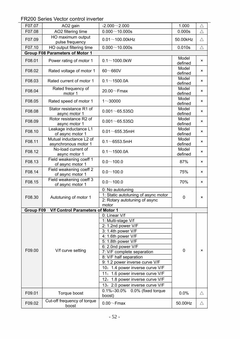
FR200 Series Vector control inverter
- 52 -
F07.07 AO2 gain -2.000~2.000 1.000
F07.08 AO2 filtering time 0.000~10.000s 0.000s
F07.09 HO maximum outputpulse frequency 0.01~100.00kHz 50.00kHz
F07.10 HO output filtering time 0.000~10.000s 0.010s
Group F08 Parameters of Motor 1
F08.01 Power rating of motor 1 0.1~1000.0kW Modeldefined ×
F08.02 Rated voltage of motor 1 60~660V Modeldefined ×
F08.03 Rated current of motor 1 0.1~1500.0A Modeldefined ×
F08.04 Rated frequency ofmotor 1 20.00~Fmax Model
defined ×
F08.05 Rated speed of motor 1 1~30000 Modeldefined ×
F08.08 Stator resistance R1 ofasync motor 1 0.001~65.535Ω Model
defined ×
F08.09 Rotor resistance R2 ofasync motor 1 0.001~65.535Ω Model
defined ×
F08.10 Leakage inductance L1of async motor 1 0.01~655.35mH Model
defined ×
F08.11 Mutual inductance L2 ofasynchronous motor 1 0.1~6553.5mH Model
defined ×
F08.12 No-load current ofasync motor 1 0.1~1500.0A Model
defined ×
F08.13 Field weakening coeff 1of async motor 1 0.0~100.0 87% ×
F08.14 Field weakening coeff 2of async motor 1 0.0~100.0 75% ×
F08.15 Field weakening coeff 3of async motor 1 0.0~100.0 70% ×
F08.30 Autotuning of motor 1
0: No autotuning
0 ×1: Static autotuning of async motor2: Rotary autotuning of asyncmotor
Group F09 V/f Control Parameters of Motor 1
F09.00 V/f curve setting
0: Linear V/f
0 ×
1: Multi-stage V/f2: 1.2nd power V/F3: 1.4th power V/F4: 1.6th power V/F5: 1.8th power V/F6: 2.0nd power V/F7: V/F complete separation8: V/F half separation9: 1.2 power inverse curve V/F10:1.4 power inverse curve V/F11:1.6 power inverse curve V/F12:1.8 power inverse curve V/F13:2.0 power inverse curve V/F
F09.01 Torque boost 0.1%–30.0% 0.0% (fixed torqueboost) 0.0%
F09.02 Cut-off frequency of torqueboost 0.00~Fmax 50.00Hz
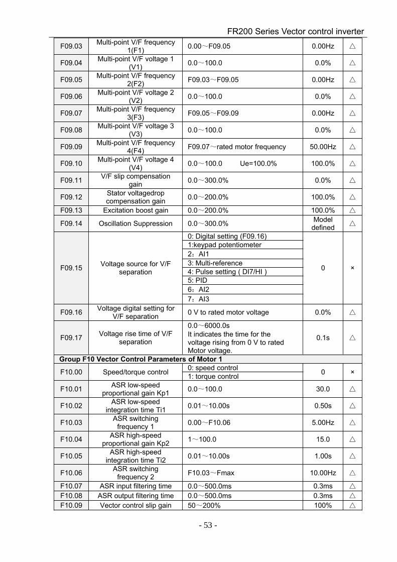
FR200 Series Vector control inverter
- 53 -
F09.03 Multi-point V/F frequency1(F1) 0.00~F09.05 0.00Hz
F09.04 Multi-point V/F voltage 1(V1) 0.0~100.0 0.0%
F09.05 Multi-point V/F frequency2(F2) F09.03~F09.05 0.00Hz
F09.06 Multi-point V/F voltage 2(V2) 0.0~100.0 0.0%
F09.07 Multi-point V/F frequency3(F3) F09.05~F09.09 0.00Hz
F09.08 Multi-point V/F voltage 3(V3) 0.0~100.0 0.0%
F09.09 Multi-point V/F frequency4(F4) F09.07~rated motor frequency 50.00Hz
F09.10 Multi-point V/F voltage 4(V4) 0.0~100.0 Ue=100.0% 100.0%
F09.11 V/F slip compensationgain 0.0~300.0% 0.0%
F09.12 Stator voltagedropcompensation gain 0.0~200.0% 100.0%
F09.13 Excitation boost gain 0.0~200.0% 100.0%
F09.14 Oscillation Suppression 0.0~300.0% Modeldefined
F09.15 Voltage source for V/Fseparation
0: Digital setting (F09.16)
0 ×
1:keypad potentiometer2:AI13: Multi-reference4: Pulse setting ( DI7/HI )5: PID6:AI27:AI3
F09.16 Voltage digital setting forV/F separation 0 V to rated motor voltage 0.0%
F09.17 Voltage rise time of V/Fseparation
0.0~6000.0sIt indicates the time for thevoltage rising from 0 V to ratedMotor voltage.
0.1s
Group F10 Vector Control Parameters of Motor 1
F10.00 Speed/torque control 0: speed control 0 ×1: torque control
F10.01 ASR low-speedproportional gain Kp1 0.0~100.0 30.0
F10.02 ASR low-speedintegration time Ti1 0.01~10.00s 0.50s
F10.03 ASR switchingfrequency 1 0.00~F10.06 5.00Hz
F10.04 ASR high-speedproportional gain Kp2 1~100.0 15.0
F10.05 ASR high-speedintegration time Ti2 0.01~10.00s 1.00s
F10.06 ASR switchingfrequency 2 F10.03~Fmax 10.00Hz
F10.07 ASR input filtering time 0.0~500.0ms 0.3ms
F10.08 ASR output filtering time 0.0~500.0ms 0.3ms
F10.09 Vector control slip gain 50~200% 100%
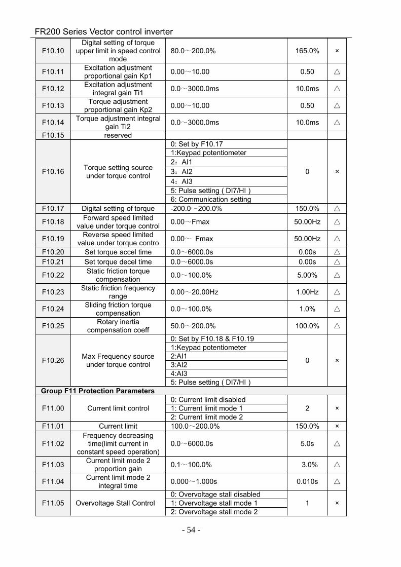
FR200 Series Vector control inverter
- 54 -
F10.10Digital setting of torque
upper limit in speed controlmode
80.0~200.0% 165.0% ×
F10.11 Excitation adjustmentproportional gain Kp1 0.00~10.00 0.50
F10.12 Excitation adjustmentintegral gain Ti1 0.0~3000.0ms 10.0ms
F10.13 Torque adjustmentproportional gain Kp2 0.00~10.00 0.50
F10.14 Torque adjustment integralgain Ti2 0.0~3000.0ms 10.0ms
F10.15 reserved
F10.16 Torque setting sourceunder torque control
0: Set by F10.17
0 ×
1:Keypad potentiometer2:AI13:AI24:AI35: Pulse setting ( DI7/HI )6: Communication setting
F10.17 Digital setting of torque -200.0~200.0% 150.0%
F10.18 Forward speed limitedvalue under torque control 0.00~Fmax 50.00Hz
F10.19 Reverse speed limitedvalue under torque contro 0.00~ Fmax 50.00Hz
F10.20 Set torque accel time 0.0~6000.0s 0.00s
F10.21 Set torque decel time 0.0~6000.0s 0.00s
F10.22 Static friction torquecompensation 0.0~100.0% 5.00%
F10.23 Static friction frequencyrange 0.00~20.00Hz 1.00Hz
F10.24 Sliding friction torquecompensation 0.0~100.0% 1.0%
F10.25 Rotary inertiacompensation coeff 50.0~200.0% 100.0%
F10.26 Max Frequency sourceunder torque control
0: Set by F10.18 & F10.19
0 ×
1:Keypad potentiometer2:AI13:AI24:AI35: Pulse setting ( DI7/HI )
Group F11 Protection Parameters
F11.00 Current limit control0: Current limit disabled
2 ×1: Current limit mode 12: Current limit mode 2
F11.01 Current limit 100.0~200.0% 150.0% ×
F11.02Frequency decreasing
time(limit current inconstant speed operation)
0.0~6000.0s 5.0s
F11.03 Current limit mode 2proportion gain 0.1~100.0% 3.0%
F11.04 Current limit mode 2integral time 0.000~1.000s 0.010s
F11.05 Overvoltage Stall Control0: Overvoltage stall disabled
1 ×1: Overvoltage stall mode 12: Overvoltage stall mode 2
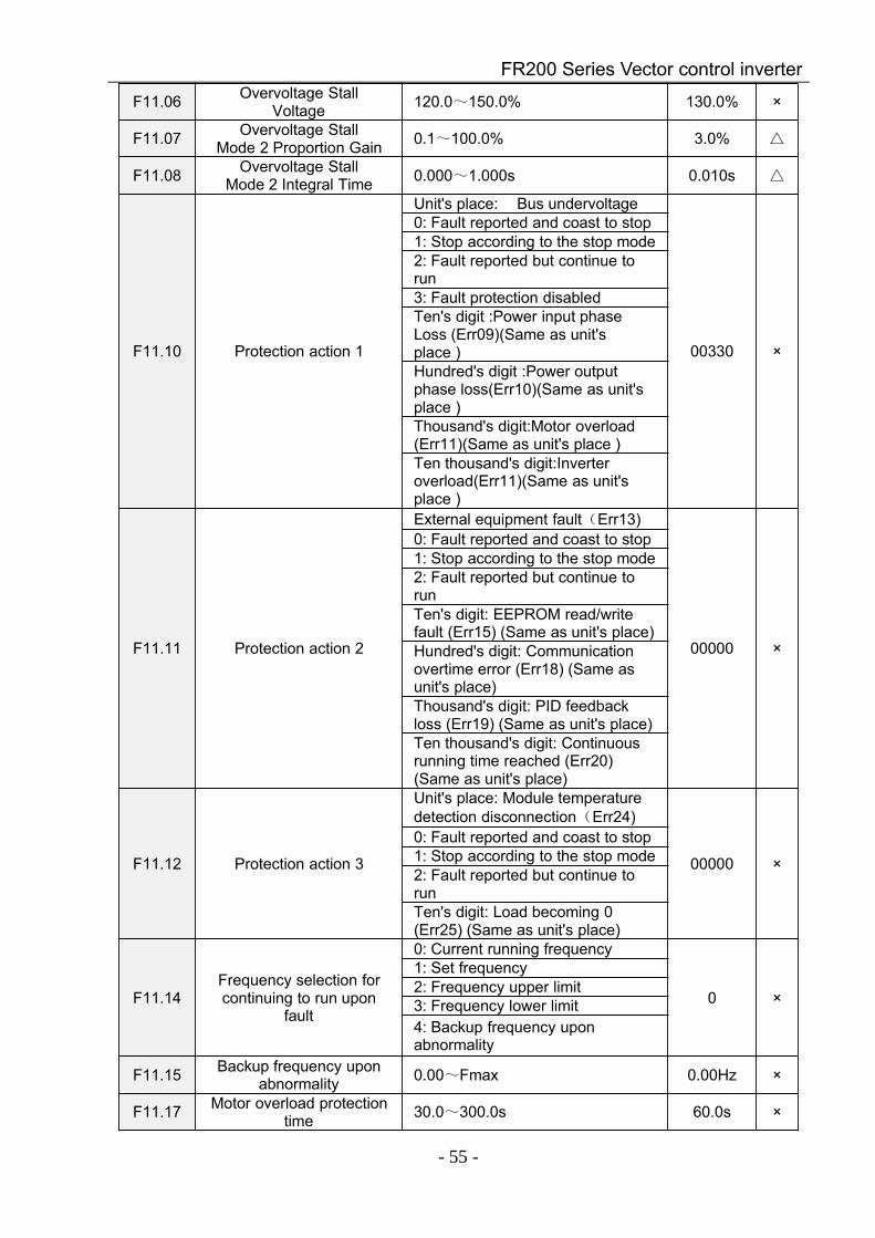
FR200 Series Vector control inverter
- 55 -
F11.06 Overvoltage StallVoltage 120.0~150.0% 130.0% ×
F11.07 Overvoltage StallMode 2 Proportion Gain 0.1~100.0% 3.0%
F11.08 Overvoltage StallMode 2 Integral Time 0.000~1.000s 0.010s
F11.10 Protection action 1
Unit's place: Bus undervoltage
00330 ×
0: Fault reported and coast to stop1: Stop according to the stop mode2: Fault reported but continue torun3: Fault protection disabledTen's digit :Power input phaseLoss (Err09)(Same as unit'splace )Hundred's digit :Power outputphase loss(Err10)(Same as unit'splace )Thousand's digit:Motor overload(Err11)(Same as unit's place )Ten thousand's digit:Inverteroverload(Err11)(Same as unit'splace )
F11.11 Protection action 2
External equipment fault(Err13)
00000 ×
0: Fault reported and coast to stop1: Stop according to the stop mode2: Fault reported but continue torunTen's digit: EEPROM read/writefault (Err15) (Same as unit's place)Hundred's digit: Communicationovertime error (Err18) (Same asunit's place)Thousand's digit: PID feedbackloss (Err19) (Same as unit's place)Ten thousand's digit: Continuousrunning time reached (Err20)(Same as unit's place)
F11.12 Protection action 3
Unit's place: Module temperaturedetection disconnection(Err24)
00000 ×
0: Fault reported and coast to stop1: Stop according to the stop mode2: Fault reported but continue torunTen's digit: Load becoming 0(Err25) (Same as unit's place)
F11.14Frequency selection forcontinuing to run upon
fault
0: Current running frequency
0 ×
1: Set frequency2: Frequency upper limit3: Frequency lower limit4: Backup frequency uponabnormality
F11.15 Backup frequency uponabnormality 0.00~Fmax 0.00Hz ×
F11.17 Motor overload protectiontime 30.0~300.0s 60.0s ×

FR200 Series Vector control inverter
- 56 -
F11.18 Overload alarm
Unit's place: detection option:
00 ×
0: Always detect1: Detect at constant speed onlyTen's digit : compared object0: Rated current of motor1: Rated current of drive
F11.19 Overload alarm threshold 20.0~200.0% 130.0% ×
F11.20Overload alarm
activated time thatexceeding threshold
0.1~60.0s 5.0s ×
F11.21 Inverter overheat warningthreshold 50~overheat Temperature Model
defined ×
F11.22 Detection level of powerloss 5.0~100.0% 20.0% ×
F11.23 Detection time of powerloss 0.1~60.0s 5.0s ×
F11.24Action selection at
instantaneous powerfailure
0: Disabled1 ×
1: Enabled
F11.25Decel time at
instantaneous powerfailure
0.0~6000.0s 5.0s
F11.26 Rapid current limit 0: Disabled 0 ×1: Enabled
F11.27 Times of automaticreset 0~20 0 ×
F11.28 Interval of automaticreset 0.1~100.0s 1.0s ×
F11.29 DO action during fault autoreset
0: Not act0 ×1: Act
Group F12: Multi-Reference and Simple PLC FunctionF12.00 Reference 0 -100.0~100.0% 0.0%
F12.01 Reference 1 -100.0~100.0% 0.0%
F12.02 Reference 2 -100.0~100.0% 0.0%
F12.03 Reference 3 -100.0~100.0% 0.0%
F12.04 Reference 4 -100.0~100.0% 0.0%
F12.05 Reference 5 -100.0~100.0% 0.0%
F12.06 Reference 6 -100.0~100.0% 0.0%
F12.07 Reference 7 -100.0~100.0% 0.0%
F12.08 Reference 8 -100.0~100.0% 0.0%
F12.09 Reference 9 -100.0~100.0% 0.0%
F12.10 Reference 10 -100.0~100.0% 0.0%
F12.11 Reference 11 -100.0~100.0% 0.0%
F12.12 Reference 12 -100.0~100.0% 0.0%
F12.13 Reference 13 -100.0~100.0% 0.0%
F12.14 Reference 14 -100.0~100.0% 0.0%
F12.15 Reference 15 -100.0~100.0% 0.0%
F12.16 Reference 0 source
0: Digital setting(F12.00)
0 ×
1:keypad potentiometer2:AI13: Process PID output4: X7/HI pulse input5:AI2
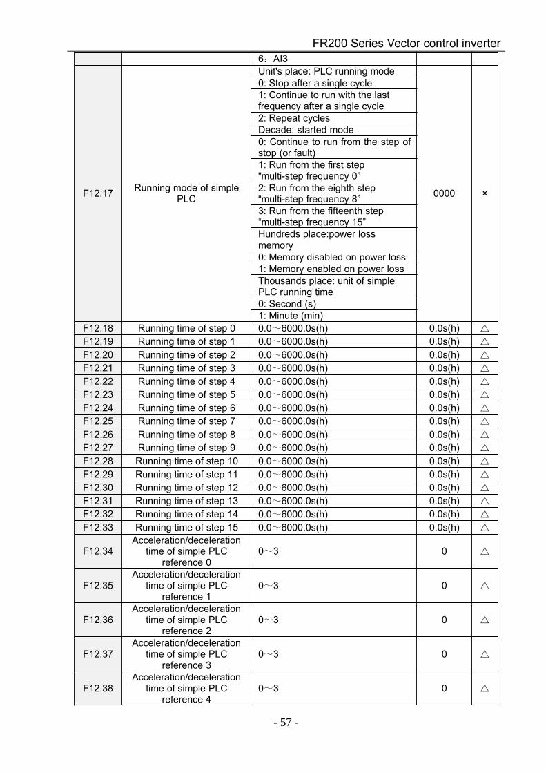
FR200 Series Vector control inverter
- 57 -
6:AI3
F12.17 Running mode of simplePLC
Unit's place: PLC running mode
0000 ×
0: Stop after a single cycle1: Continue to run with the lastfrequency after a single cycle2: Repeat cyclesDecade: started mode0: Continue to run from the step ofstop (or fault)1: Run from the first step“multi-step frequency 0”2: Run from the eighth step“multi-step frequency 8”3: Run from the fifteenth step“multi-step frequency 15”Hundreds place:power lossmemory0: Memory disabled on power loss1: Memory enabled on power lossThousands place: unit of simplePLC running time0: Second (s)1: Minute (min)
F12.18 Running time of step 0 0.0~6000.0s(h) 0.0s(h)
F12.19 Running time of step 1 0.0~6000.0s(h) 0.0s(h)
F12.20 Running time of step 2 0.0~6000.0s(h) 0.0s(h)
F12.21 Running time of step 3 0.0~6000.0s(h) 0.0s(h)
F12.22 Running time of step 4 0.0~6000.0s(h) 0.0s(h)
F12.23 Running time of step 5 0.0~6000.0s(h) 0.0s(h)
F12.24 Running time of step 6 0.0~6000.0s(h) 0.0s(h)
F12.25 Running time of step 7 0.0~6000.0s(h) 0.0s(h)
F12.26 Running time of step 8 0.0~6000.0s(h) 0.0s(h)
F12.27 Running time of step 9 0.0~6000.0s(h) 0.0s(h)
F12.28 Running time of step 10 0.0~6000.0s(h) 0.0s(h)
F12.29 Running time of step 11 0.0~6000.0s(h) 0.0s(h)
F12.30 Running time of step 12 0.0~6000.0s(h) 0.0s(h)
F12.31 Running time of step 13 0.0~6000.0s(h) 0.0s(h)
F12.32 Running time of step 14 0.0~6000.0s(h) 0.0s(h)
F12.33 Running time of step 15 0.0~6000.0s(h) 0.0s(h)
F12.34Acceleration/deceleration
time of simple PLCreference 0
0~3 0
F12.35Acceleration/deceleration
time of simple PLCreference 1
0~3 0
F12.36Acceleration/deceleration
time of simple PLCreference 2
0~3 0
F12.37Acceleration/deceleration
time of simple PLCreference 3
0~3 0
F12.38Acceleration/deceleration
time of simple PLCreference 4
0~3 0
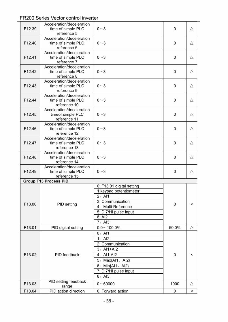
FR200 Series Vector control inverter
- 58 -
F12.39Acceleration/deceleration
time of simple PLCreference 5
0~3 0
F12.40Acceleration/deceleration
time of simple PLCreference 6
0~3 0
F12.41Acceleration/deceleration
time of simple PLCreference 7
0~3 0
F12.42Acceleration/deceleration
time of simple PLCreference 8
0~3 0
F12.43Acceleration/deceleration
time of simple PLCreference 9
0~3 0
F12.44Acceleration/deceleration
time of simple PLCreference 10
0~3 0
F12.45Acceleration/deceleration
timeof simple PLCreference 11
0~3 0
F12.46Acceleration/deceleration
time of simple PLCreference 12
0~3 0
F12.47Acceleration/deceleration
time of simple PLCreference 13
0~3 0
F12.48Acceleration/deceleration
time of simple PLCreference 14
0~3 0
F12.49Acceleration/deceleration
time of simple PLCreference 15
0~3 0
Group F13 Process PID
F13.00 PID setting
0: F13.01 digital setting
0 ×
1:keypad potentiometer2:AI13: Communication4:Multi-Reference5: DI7/HI pulse input6: AI27:AI3
F13.01 PID digital setting 0.0~100.0% 50.0%
F13.02 PID feedback
0:AI1
0 ×
1:AI22: Communication3:AI1+AI24:AI1-AI25:MaxAI1,AI26:MinAI1,AI27: DI7/HI pulse input8:AI3
F13.03 PID setting feedbackrange 0~60000 1000
F13.04 PID action direction 0: Forward action 0 ×
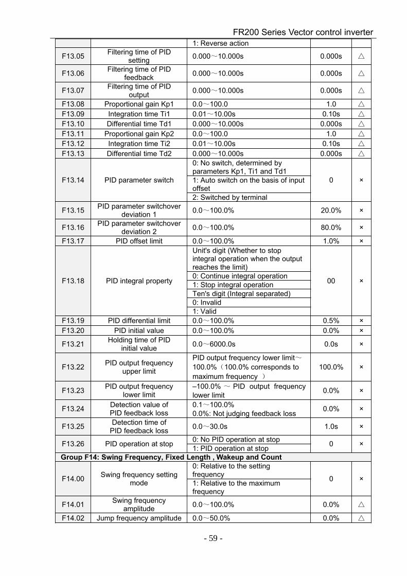
FR200 Series Vector control inverter
- 59 -
1: Reverse action
F13.05 Filtering time of PIDsetting 0.000~10.000s 0.000s
F13.06 Filtering time of PIDfeedback 0.000~10.000s 0.000s
F13.07 Filtering time of PIDoutput 0.000~10.000s 0.000s
F13.08 Proportional gain Kp1 0.0~100.0 1.0
F13.09 Integration time Ti1 0.01~10.00s 0.10s
F13.10 Differential time Td1 0.000~10.000s 0.000s
F13.11 Proportional gain Kp2 0.0~100.0 1.0
F13.12 Integration time Ti2 0.01~10.00s 0.10s
F13.13 Differential time Td2 0.000~10.000s 0.000s
F13.14 PID parameter switch
0: No switch, determined byparameters Kp1, Ti1 and Td1
0 ×1: Auto switch on the basis of inputoffset2: Switched by terminal
F13.15 PID parameter switchoverdeviation 1 0.0~100.0% 20.0% ×
F13.16 PID parameter switchoverdeviation 2 0.0~100.0% 80.0% ×
F13.17 PID offset limit 0.0~100.0% 1.0% ×
F13.18 PID integral property
Unit's digit (Whether to stopintegral operation when the outputreaches the limit)
00 ×0: Continue integral operation1: Stop integral operationTen's digit (Integral separated)0: Invalid1: Valid
F13.19 PID differential limit 0.0~100.0% 0.5% ×F13.20 PID initial value 0.0~100.0% 0.0% ×
F13.21 Holding time of PIDinitial value 0.0~6000.0s 0.0s ×
F13.22 PID output frequencyupper limit
PID output frequency lower limit~100.0%(100.0% corresponds tomaximum frequency )
100.0% ×
F13.23 PID output frequencylower limit
–100.0% ~ PID output frequencylower limit 0.0% ×
F13.24 Detection value ofPID feedback loss
0.1~100.0%0.0%: Not judging feedback loss 0.0% ×
F13.25 Detection time ofPID feedback loss 0.0~30.0s 1.0s ×
F13.26 PID operation at stop 0: No PID operation at stop 0 ×1: PID operation at stopGroup F14: Swing Frequency, Fixed Length , Wakeup and Count
F14.00 Swing frequency settingmode
0: Relative to the settingfrequency 0 ×1: Relative to the maximumfrequency
F14.01 Swing frequencyamplitude 0.0~100.0% 0.0%
F14.02 Jump frequency amplitude 0.0~50.0% 0.0%
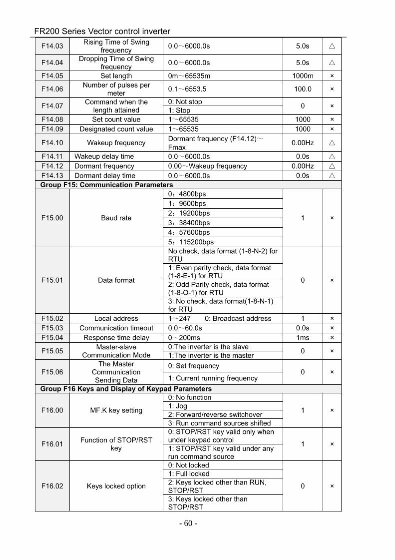
FR200 Series Vector control inverter
- 60 -
F14.03 Rising Time of Swingfrequency 0.0~6000.0s 5.0s
F14.04 Dropping Time of Swingfrequency 0.0~6000.0s 5.0s
F14.05 Set length 0m~65535m 1000m ×
F14.06 Number of pulses permeter 0.1~6553.5 100.0 ×
F14.07 Command when thelength attained
0: Not stop 0 ×1: StopF14.08 Set count value 1~65535 1000 ×F14.09 Designated count value 1~65535 1000 ×
F14.10 Wakeup frequency Dormant frequency (F14.12)~Fmax 0.00Hz
F14.11 Wakeup delay time 0.0~6000.0s 0.0s
F14.12 Dormant frequency 0.00~Wakeup frequency 0.00Hz
F14.13 Dormant delay time 0.0~6000.0s 0.0s
Group F15: Communication Parameters
F15.00 Baud rate
0:4800bps
1 ×
1:9600bps2:19200bps3:38400bps4:57600bps5:115200bps
F15.01 Data format
No check, data format (1-8-N-2) forRTU
0 ×
1: Even parity check, data format(1-8-E-1) for RTU2: Odd Parity check, data format(1-8-O-1) for RTU3: No check, data format(1-8-N-1)for RTU
F15.02 Local address 1~247 0: Broadcast address 1 ×F15.03 Communication timeout 0.0~60.0s 0.0s ×F15.04 Response time delay 0~200ms 1ms ×
F15.05 Master-slaveCommunication Mode
0:The inverter is the slave 0 ×1:The inverter is the master
F15.06The Master
CommunicationSending Data
0: Set frequency0 ×
1: Current running frequencyGroup F16 Keys and Display of Keypad Parameters
F16.00 MF.K key setting
0: No function
1 ×1: Jog2: Forward/reverse switchover3: Run command sources shifted
F16.01 Function of STOP/RSTkey
0: STOP/RST key valid only whenunder keypad control 1 ×1: STOP/RST key valid under anyrun command source
F16.02 Keys locked option
0: Not locked
0 ×
1: Full locked2: Keys locked other than RUN,STOP/RST3: Keys locked other thanSTOP/RST
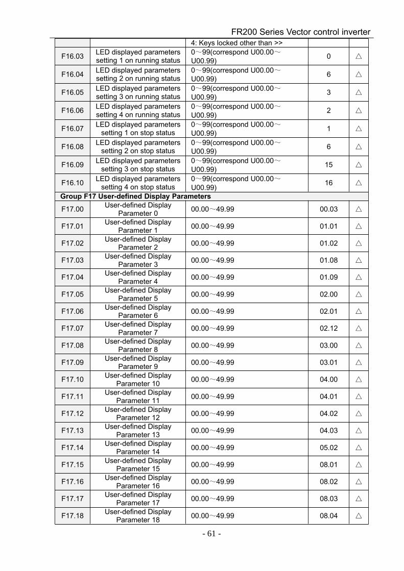
FR200 Series Vector control inverter
- 61 -
4: Keys locked other than >>
F16.03 LED displayed parameterssetting 1 on running status
0~99(correspond U00.00~U00.99) 0
F16.04 LED displayed parameterssetting 2 on running status
0~99(correspond U00.00~U00.99) 6
F16.05 LED displayed parameterssetting 3 on running status
0~99(correspond U00.00~U00.99) 3
F16.06 LED displayed parameterssetting 4 on running status
0~99(correspond U00.00~U00.99) 2
F16.07 LED displayed parameterssetting 1 on stop status
0~99(correspond U00.00~U00.99) 1
F16.08 LED displayed parameterssetting 2 on stop status
0~99(correspond U00.00~U00.99) 6
F16.09 LED displayed parameterssetting 3 on stop status
0~99(correspond U00.00~U00.99) 15
F16.10 LED displayed parameterssetting 4 on stop status
0~99(correspond U00.00~U00.99) 16
Group F17 User-defined Display Parameters
F17.00 User-defined DisplayParameter 0 00.00~49.99 00.03
F17.01 User-defined DisplayParameter 1 00.00~49.99 01.01
F17.02 User-defined DisplayParameter 2 00.00~49.99 01.02
F17.03 User-defined DisplayParameter 3 00.00~49.99 01.08
F17.04 User-defined DisplayParameter 4 00.00~49.99 01.09
F17.05 User-defined DisplayParameter 5 00.00~49.99 02.00
F17.06 User-defined DisplayParameter 6 00.00~49.99 02.01
F17.07 User-defined DisplayParameter 7 00.00~49.99 02.12
F17.08 User-defined DisplayParameter 8 00.00~49.99 03.00
F17.09 User-defined DisplayParameter 9 00.00~49.99 03.01
F17.10 User-defined DisplayParameter 10 00.00~49.99 04.00
F17.11 User-defined DisplayParameter 11 00.00~49.99 04.01
F17.12 User-defined DisplayParameter 12 00.00~49.99 04.02
F17.13 User-defined DisplayParameter 13 00.00~49.99 04.03
F17.14 User-defined DisplayParameter 14 00.00~49.99 05.02
F17.15 User-defined DisplayParameter 15 00.00~49.99 08.01
F17.16 User-defined DisplayParameter 16 00.00~49.99 08.02
F17.17 User-defined DisplayParameter 17 00.00~49.99 08.03
F17.18 User-defined DisplayParameter 18 00.00~49.99 08.04
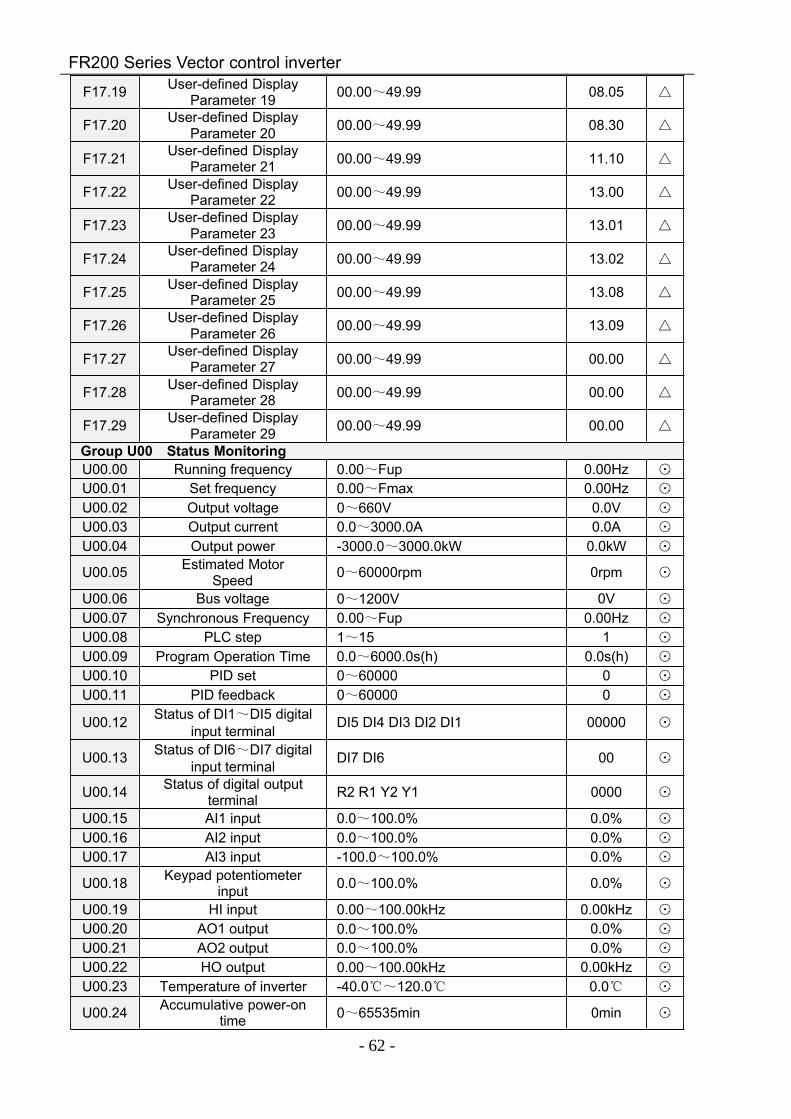
FR200 Series Vector control inverter
- 62 -
F17.19 User-defined DisplayParameter 19 00.00~49.99 08.05
F17.20 User-defined DisplayParameter 20 00.00~49.99 08.30
F17.21 User-defined DisplayParameter 21 00.00~49.99 11.10
F17.22 User-defined DisplayParameter 22 00.00~49.99 13.00
F17.23 User-defined DisplayParameter 23 00.00~49.99 13.01
F17.24 User-defined DisplayParameter 24 00.00~49.99 13.02
F17.25 User-defined DisplayParameter 25 00.00~49.99 13.08
F17.26 User-defined DisplayParameter 26 00.00~49.99 13.09
F17.27 User-defined DisplayParameter 27 00.00~49.99 00.00
F17.28 User-defined DisplayParameter 28 00.00~49.99 00.00
F17.29 User-defined DisplayParameter 29 00.00~49.99 00.00
Group U00 Status MonitoringU00.00 Running frequency 0.00~Fup 0.00Hz ⊙
U00.01 Set frequency 0.00~Fmax 0.00Hz ⊙
U00.02 Output voltage 0~660V 0.0V ⊙
U00.03 Output current 0.0~3000.0A 0.0A ⊙
U00.04 Output power -3000.0~3000.0kW 0.0kW ⊙
U00.05 Estimated MotorSpeed 0~60000rpm 0rpm ⊙
U00.06 Bus voltage 0~1200V 0V ⊙
U00.07 Synchronous Frequency 0.00~Fup 0.00Hz ⊙
U00.08 PLC step 1~15 1 ⊙
U00.09 Program Operation Time 0.0~6000.0s(h) 0.0s(h) ⊙
U00.10 PID set 0~60000 0 ⊙
U00.11 PID feedback 0~60000 0 ⊙
U00.12 Status of DI1~DI5 digitalinput terminal DI5 DI4 DI3 DI2 DI1 00000 ⊙
U00.13 Status of DI6~DI7 digitalinput terminal DI7 DI6 00 ⊙
U00.14 Status of digital outputterminal R2 R1 Y2 Y1 0000 ⊙
U00.15 AI1 input 0.0~100.0% 0.0% ⊙
U00.16 AI2 input 0.0~100.0% 0.0% ⊙
U00.17 AI3 input -100.0~100.0% 0.0% ⊙
U00.18 Keypad potentiometerinput 0.0~100.0% 0.0% ⊙
U00.19 HI input 0.00~100.00kHz 0.00kHz ⊙
U00.20 AO1 output 0.0~100.0% 0.0% ⊙
U00.21 AO2 output 0.0~100.0% 0.0% ⊙
U00.22 HO output 0.00~100.00kHz 0.00kHz ⊙
U00.23 Temperature of inverter -40.0~120.0 0.0 ⊙
U00.24 Accumulative power-ontime 0~65535min 0min ⊙
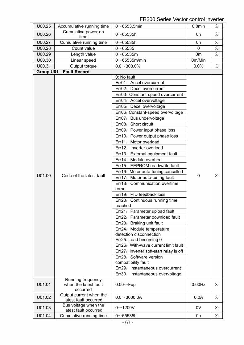
FR200 Series Vector control inverter
- 63 -
U00.25 Accumulative running time 0~6553.5min 0.0min ⊙
U00.26 Cumulative power-ontime 0~65535h 0h ⊙
U00.27 Cumulative running time 0~65535h 0h ⊙
U00.28 Count value 0~65535 0 ⊙
U00.29 Length value 0~65535m 0m ⊙
U00.30 Linear speed 0~65535m/min 0m/MinU00.31 Output torque 0.0~300.0% 0.0% ⊙
Group U01 Fault Record
U01.00 Code of the latest fault
0: No fault
0 ⊙
Err01:Accel overcurrentErr02:Decel overcurrentErr03:Constant-speed overcurrentErr04:Accel overvoltageErr05:Decel overvoltageErr06:Constant-speed overvoltageErr07:Bus undervoltageErr08:Short circuitErr09:Power input phase lossErr10:Power output phase lossErr11:Motor overloadErr12:Inverter overloadErr13:External equipment faultErr14:Module overheatErr15:EEPROM read/write faultErr16:Motor auto-tuning cancelledErr17:Motor auto-tuning faultErr18:Communication overtimeerrorErr19:PID feedback lossErr20:Continuous running timereachedErr21:Parameter upload faultErr22:Parameter download faultErr23:Braking unit faultErr24:Module temperaturedetection disconnectionErr25: Load becoming 0Err26:With-wave current limit faultErr27:Inverter soft-start relay is offErr28:Software versioncompatibility faultErr29:Instantaneous overcurrentErr30:Instantaneous overvoltage
U01.01Running frequencywhen the latest fault
occurred0.00~Fup 0.00Hz ⊙
U01.02 Output current when thelatest fault occurred 0.0~3000.0A 0.0A ⊙
U01.03 Bus voltage when thelatest fault occurred 0~1200V 0V ⊙
U01.04 Cumulative running time 0~65535h 0h ⊙
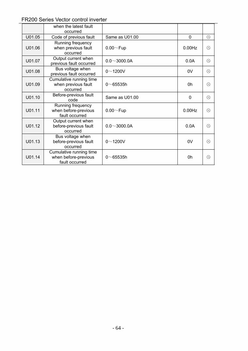
FR200 Series Vector control inverter
- 64 -
when the latest faultoccurred
U01.05 Code of previous fault Same as U01.00 0 ⊙
U01.06Running frequencywhen previous fault
occurred0.00~Fup 0.00Hz ⊙
U01.07 Output current whenprevious fault occurred 0.0~3000.0A 0.0A ⊙
U01.08 Bus voltage whenprevious fault occurred 0~1200V 0V ⊙
U01.09Cumulative running time
when previous faultoccurred
0~65535h 0h ⊙
U01.10 Before-previous faultcode Same as U01.00 0 ⊙
U01.11Running frequency
when before-previousfault occurred
0.00~Fup 0.00Hz ⊙
U01.12Output current whenbefore-previous fault
occurred0.0~3000.0A 0.0A ⊙
U01.13Bus voltage when
before-previous faultoccurred
0~1200V 0V ⊙
U01.14Cumulative running time
when before-previousfault occurred
0~65535h 0h ⊙
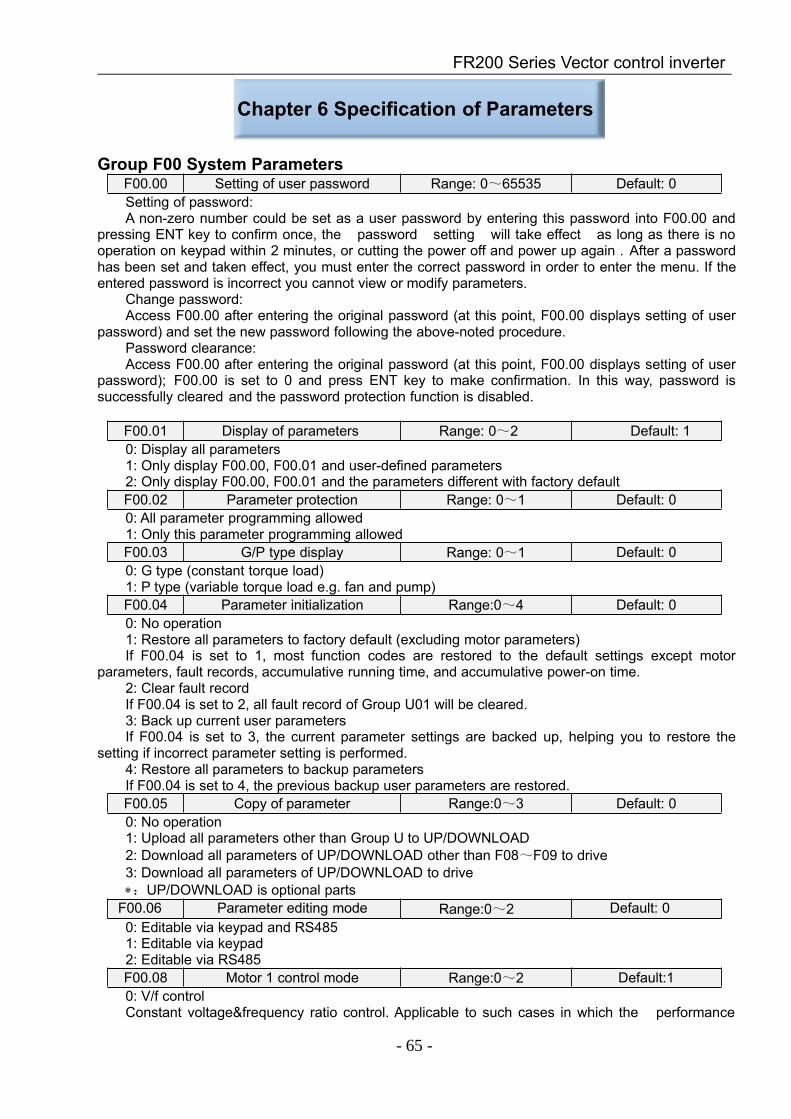
FR200 Series Vector control inverter
- 65 -
Chapter 6 Specification of Parameters
Group F00 System ParametersF00.00 Setting of user password Range: 0~65535 Default: 0Setting of password:A non-zero number could be set as a user password by entering this password into F00.00 and
pressing ENT key to confirm once, the password setting will take effect as long as there is nooperation on keypad within 2 minutes, or cutting the power off and power up again . After a passwordhas been set and taken effect, you must enter the correct password in order to enter the menu. If theentered password is incorrect you cannot view or modify parameters.
Change password:Access F00.00 after entering the original password (at this point, F00.00 displays setting of user
password) and set the new password following the above-noted procedure.Password clearance:Access F00.00 after entering the original password (at this point, F00.00 displays setting of user
password); F00.00 is set to 0 and press ENT key to make confirmation. In this way, password issuccessfully cleared and the password protection function is disabled.
F00.01 Display of parameters Range: 0~2 Default: 10: Display all parameters1: Only display F00.00, F00.01 and user-defined parameters2: Only display F00.00, F00.01 and the parameters different with factory defaultF00.02 Parameter protection Range: 0~1 Default: 00: All parameter programming allowed1: Only this parameter programming allowedF00.03 G/P type display Range: 0~1 Default: 00: G type (constant torque load)1: P type (variable torque load e.g. fan and pump)F00.04 Parameter initialization Range:0~4 Default: 00: No operation1: Restore all parameters to factory default (excluding motor parameters)If F00.04 is set to 1, most function codes are restored to the default settings except motor
parameters, fault records, accumulative running time, and accumulative power-on time.2: Clear fault recordIf F00.04 is set to 2, all fault record of Group U01 will be cleared.3: Back up current user parametersIf F00.04 is set to 3, the current parameter settings are backed up, helping you to restore the
setting if incorrect parameter setting is performed.4: Restore all parameters to backup parametersIf F00.04 is set to 4, the previous backup user parameters are restored.F00.05 Copy of parameter Range:0~3 Default: 00: No operation1: Upload all parameters other than Group U to UP/DOWNLOAD2: Download all parameters of UP/DOWNLOAD other than F08~F09 to drive3: Download all parameters of UP/DOWNLOAD to drive∗:UP/DOWNLOAD is optional parts
F00.06 Parameter editing mode Range:0~2 Default: 00: Editable via keypad and RS4851: Editable via keypad2: Editable via RS485F00.08 Motor 1 control mode Range:0~2 Default:10: V/f controlConstant voltage&frequency ratio control. Applicable to such cases in which the performance
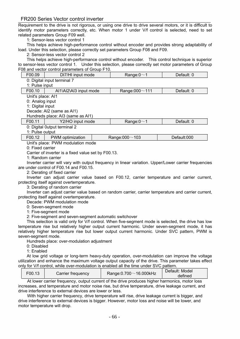
FR200 Series Vector control inverter
- 66 -
Requirement to the drive is not rigorous, or using one drive to drive several motors, or it is difficult toidentify motor parameters correctly, etc. When motor 1 under V/f control is selected, need to setrelated parameters Group F09 well.
1: Sensor-less vector control 1This helps achieve high-performance control without encoder and provides strong adaptability of
load. Under this selection, please correctly set parameters Group F08 and F09.2: Sensor-less vector control 2This helps achieve high-performance control without encoder. This control technique is superior
to sensor-less vector control 1. Under this selection, please correctly set motor parameters of GroupF08 and vector control parameters of Group F10.
F00.09 DI7/HI input mode Range:0~1 Default: 00: Digital input terminal 71: Pulse inputF00.10 AI1\AI2\AI3 input mode Range:000~111 Default: 0Unit's place: AI10: Analog input1: Digital inputDecade: AI2 (same as AI1)Hundreds place: AI3 (same as AI1)F00.11 Y2/HO input mode Range:0~1 Default: 00: Digital 0utput terminal 21: Pulse outputF00.12 PWM optimization Range:000~103 Default:000Unit's place: PWM modulation mode0: Fixed carrierCarrier of inverter is a fixed value set by F00.13.1: Random carrierInverter carrier will vary with output frequency in linear variation. Upper/Lower carrier frequencies
are under control of F00.14 and F00.15.2: Derating of fixed carrierInverter can adjust carrier value based on F00.12, carrier temperature and carrier current,
protecting itself against overtemperature.3: Derating of random carrierInverter can adjust carrier value based on random carrier, carrier temperature and carrier current,
protecting itself against overtemperature.Decade: PWM modulation mode0: Seven-segment mode1: Five-segment mode2: Five-segment and seven-segment automatic switchoverThis selection is valid only for V/f control. When five-segment mode is selected, the drive has low
temperature rise but relatively higher output current harmonic. Under seven-segment mode, it hasrelatively higher temperature rise but lower output current harmonic. Under SVC pattern, PWM isseven-segment mode.
Hundreds place: over-modulation adjustment0: Disabled1: EnabledAt low grid voltage or long-term heavy-duty operation, over-modulation can improve the voltage
utilization and enhance the maximum voltage output capacity of the drive. This parameter takes effectonly for V/f control, while over-modulation is enabled all the time under SVC pattern.
F00.13 Carrier frequency Range:0.700~16.000kHz Default: Modeldefined
At lower carrier frequency, output current of the drive produces higher harmonics, motor lossincreases, and temperature and motor noise rise, but drive temperature, drive leakage current, anddrive interference to external devices are lower or less.
With higher carrier frequency, drive temperature will rise, drive leakage current is bigger, anddrive interference to external devices is bigger. However, motor loss and noise will be lower, andmotor temperature will drop.
FR200 Series Vector control inverter
- 67 -
The table below specifies the setting range and factory default of PWM carrier frequency of thedrives at different power ratings:
Power rating of theinverter Range Default
≤15kW 0.700k~16.000k 4.000k18.5kW~45kW 0.700k~8.000k 4.000k55kW~75kW 0.700k~6.000k 3.000k≥90kW 0.700k~3.000k 2.000k
PWM carrier frequency setting method:1) When the motor line is too long, reduce carrier frequency.2) When torque at low speed is unstable, reduce carrier frequency.3) If the drive produces severe interference to surrounding equipment, reduce carrier frequency.4) Leakage current of the drive is big, reduce carrier frequency.5) Drive temperature rise is relatively high, reduce carrier frequency.6) Motor temperature rise is relatively high, increase carrier frequency.7) Motor noise is relatively big, increase carrier frequency.ATTENTION:Increasing carrier frequency can reduce motor noise and heat, but it will increase temperature of
inverter. When the carrier frequency is higher than the default, inverter rated power shall be decreasedby 5% for every additional 1 kHz carrier frequency.
F00.14 Upper carrier frequency Range:0.700~16.000kHz Default:8.000 kHzF00.15 Lower carrier frequency Range:0.700~16.000kHz Default:2.000 kHzInverter carrier will vary with output frequency in linear variation. Upper/Lower carrier frequencies
are under control of F00.14 and F00.15.F00.16 Output voltage Range:5.0~100.0% Default:100.0%
Adjust the percentage of output voltage to input voltage.F00.17 AVR Range:0~2 Default: 00: Disabled1: Enabled2: AVR is disabled if the DC bus voltage > the rated voltage of DC bus, and it will be enabled if the
DC bus voltage≤the rated voltage of DC bus.F00.18 Fan control Range:0~1 Default:1After power is on, the fan runs per the control mode after running for 2 minutes regardless of the
working status of inverter.0: The fan runs directly after inverter is power-on.1: the fan works when the AC drive is in running state. When the AC drive stops, the cooling fan
works if the heat sink temperature is higher than 42°C, and stops working if the heat sink temperatureis lower than 38°C.
F00.19 Factory password Range:0~65535 Default: 0Factory parameter
F00.20 Inverter rated power Range:0.2~710.0kW Default: Modeldefined
F00.21 Inverter rated voltage Range:220~380V Default: Modeldefined
F00.22 Inverter rated current Range:0.1~1500.0A Default: Modeldefined
F00.23 Software version Range:0.01~99.99 Default: Modeldefined
The parameters are only for reference and cannot be edited.
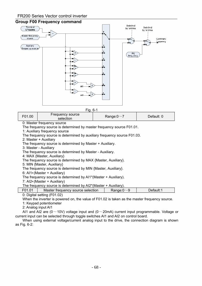
FR200 Series Vector control inverter
- 68 -
Group F00 Frequency command
Fig. 6-1
F01.00 Frequency sourceselection Range:0~7 Default: 0
0: Master frequency sourceThe frequency source is determined by master frequency source F01.01.1: Auxiliary frequency sourceThe frequency source is determined by auxiliary frequency source F01.03.2: Master + AuxiliaryThe frequency source is determined by Master + Auxiliary.3: Master - AuxiliaryThe frequency source is determined by Master - Auxiliary.4: MAX Master, AuxiliaryThe frequency source is determined by MAX Master, Auxiliary.5: MIN Master, AuxiliaryThe frequency source is determined by MIN Master, Auxiliary.6: AI1∗(Master + Auxiliary)The frequency source is determined by AI1*(Master + Auxiliary).7: AI2∗(Master + Auxiliary)The frequency source is determined by AI2*(Master + Auxiliary).F01.01 Master frequency source selection Range:0~9 Default:10: Digital setting (F01.02)When the inverter is powered on, the value of F01.02 is taken as the master frequency source.1: Keypad potentiometer2: Analog input AI1AI1 and AI2 are (0~10V) voltage input and (0~20mA) current input programmable. Voltage or
current input can be selected through toggle switches AI1 and AI2 on control board.When using external voltage/current analog input to the drive, the connection diagram is shown
as Fig. 6-2:
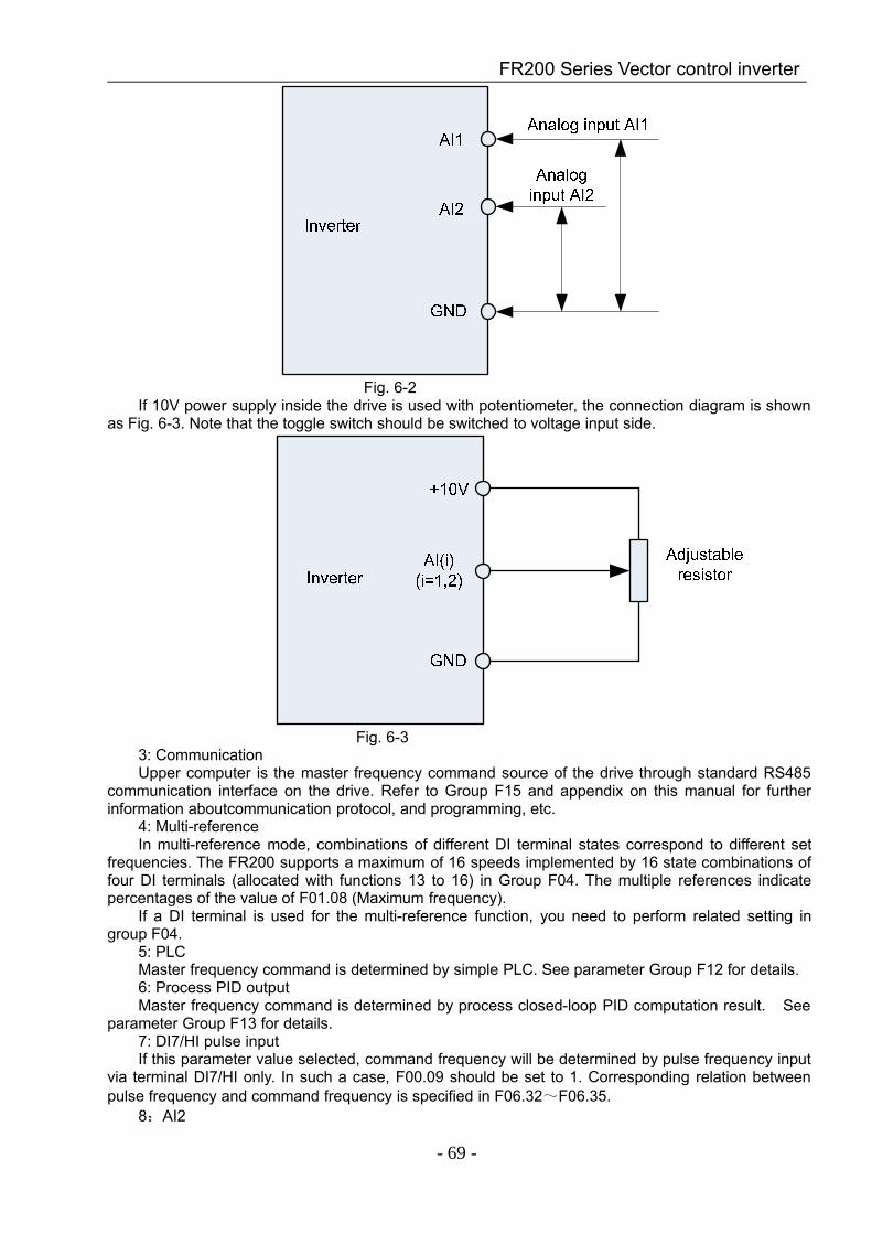
FR200 Series Vector control inverter
- 69 -
Fig. 6-2If 10V power supply inside the drive is used with potentiometer, the connection diagram is shown
as Fig. 6-3. Note that the toggle switch should be switched to voltage input side.
Fig. 6-33: CommunicationUpper computer is the master frequency command source of the drive through standard RS485
communication interface on the drive. Refer to Group F15 and appendix on this manual for furtherinformation aboutcommunication protocol, and programming, etc.
4: Multi-referenceIn multi-reference mode, combinations of different DI terminal states correspond to different set
frequencies. The FR200 supports a maximum of 16 speeds implemented by 16 state combinations offour DI terminals (allocated with functions 13 to 16) in Group F04. The multiple references indicatepercentages of the value of F01.08 (Maximum frequency).
If a DI terminal is used for the multi-reference function, you need to perform related setting ingroup F04.
5: PLCMaster frequency command is determined by simple PLC. See parameter Group F12 for details.6: Process PID outputMaster frequency command is determined by process closed-loop PID computation result. See
parameter Group F13 for details.7: DI7/HI pulse inputIf this parameter value selected, command frequency will be determined by pulse frequency input
via terminal DI7/HI only. In such a case, F00.09 should be set to 1. Corresponding relation betweenpulse frequency and command frequency is specified in F06.32~F06.35.
8:AI2
FR200 Series Vector control inverter
- 70 -
Master frequency command is determined by analog input AI2.9:AI3Master frequency command is determined by analog input AI3.
F01.02 Digital setting of masterfrequency Range:0.00~FmaxHz Default:0.00Hz
When master frequency source selection F01.01 is set to 1, this parameter value will be the initialvalue of master frequency command.
F01.03 Auxiliary frequency commandsource Range:0~9 Default: 0
0: Digital setting (F01.04)When the inverter is powered on, the value of F01.02 is taken as the master frequency source.1: Keypad potentiometerAuxiliary frequency command is determined by keypad potentiometer.2: Analog input AI1Auxiliary frequency command is determined by analog input AI1.3: CommunicationUpper computer is the auxiliary frequency command source of the drive through standard RS485
communication interface on the drive.4: Multi-referenceAuxiliary frequency command is determined by multi-reference. See parameter Group F04 for
details.5: PLCAuxiliary frequency command is determined by simple PLC. See parameter Group F12 for details.6: Process PID outputAuxiliary frequency command is determined by process PID computation result. See parameter
Group F13 for details.7: DI7/HI pulse inputAuxiliary frequency command is determined by DI7/HI pulse input.8:AI2Auxiliary frequency command is determined by analog input AI2.9:AI3Auxiliary frequency command is determined by analog input AI3.
F01.04 Digital setting of auxiliaryfrequency Range:0.00~Fmax Default:0.00Hz
When auxiliary frequency command F01.03 is set to 0, this parameter value should be the initialvalue of auxiliary frequency command.
F01.05 Range of auxiliary frequency Range:0~1 Default: 00: Relative to maximum frequency1: Relative to master frequencySee F01.06 specification for details.F01.06 Coeff of auxiliary frequency Range:0.0~150.0% Default:100.0%F01.05 and F01.06 will determine the final output value of auxiliary frequency command.When F01.05 is set to 0 (relative to maximum frequency):The auxiliary frequency= the auxiliary frequency ∗F01.06.When F01.05 is set to 1 (relative to master frequency):The setting range of the auxiliary frequency varies according to the master frequency.The auxiliary frequency= the auxiliary frequency ∗F01.06∗abs (the master frequency)/F01.08.F01.07 Jog frequency Range:0.00~Fmax Default:5.00HzThis parameter sets the running frequency during jog.F01.08 Maximum frequency Range:20.00~600.00 Default:50.00HzMaximum frequency of F01.08 is the maximum allowable output frequency of drive.F01.09 Upper limit frequency Range:Fdown~Fmax Default:50.00HzF01.10 Lower limit frequency Range:0.00~Fup Default:50.00HzF01.09upper limit frequency is the user-defined maximum allowable running frequency; F01.10
lower limit frequency is user-defined minimum allowable running frequency.
FR200 Series Vector control inverter
- 71 -
ATTENTION:1. Fup and Fdown shall be set as per motor nameplate parameters and working conditions. Motor
shall not work in low frequency for a long time. Otherwise, motor service lifespan will be shortened dueto overheating.
2. Correlation of Fmax, Fup and Fdown: 0.00Hz ≤Fdown ≤Fup≤Fmax ≤600.00Hz
F01.11Operation when commandfrequency lower than lower
limit frequencyRange:0~1 Default: 0
F01.12 Lower limit frequencyrunning time Range:0.0~6000.0s Default:0.0s
0: Run at lower limit frequencyIn case command frequency is lower than lower limit frequency, the running should be at lower
limit frequency.1: Run at 0 Hz would be activated after the time delayIf frequency command is lower than lower limit frequency, run at 0 Hz would be activated after the
time delay set by F01.12. When lower limit frequency is 0, this limitation is invalid.Group F02 Start/Stop Control Start/Stop Control
F02.00 Run command Range:0~2 Default: 0This parameter sets run command source. Run commands include "start, stop, forward ,
reverse,jog", etc.0: Keypad control (LED off)Control run command through RUN, STOP/RESET and MF.K keys on keypad (set multifunction
key MF.K to JOG by F16.00). Refer to Chapter 4 about the operation of keypad.1: Terminal control (LED on)Controls run command via DI terminals. Perform FORWARD and REVERSE by DI terminals. The
control modes are two-wire mode and three-wire mode selectable. See Group F04 for details ofdesignation and wiring regulation of DI terminals.
2: Communication control (LED blinking)Master device is able to control run command through built-in RS485 serial communication
interface of drive. Refer to parameters Group F15 and appendix for further information aboutprogramming.
Run command from keypad, terminals and communication can be switched by terminals "runcommand switched to keypad control", "run command switched to terminal control" and "run commandswitched to communication control".
Multifunction key MF.K can be set to "run command sources shifted" key through parameterF16.00. When MF key is pressed under this setting; run command will be shifted during keypad control,terminal control and communication control circularly.
F02.01 Running direction Range:0~1 Default: 00: Forward1: ReverseYou can change the rotation direction of the motor just by modifying this parameter without
changing the motor wiring. Modifying this parameter is equivalent to exchanging any two of the motor'sU, V, W wires.
Note:The motor will resume running in the original direction after parameter initialization. Do not use
this function in applications where changing the rotating direction of the motor is prohibited aftersystem commissioning is complete.
F02.02 Reverse-proof action Range:0~1 Default: 00: Reverse enabled1: Reverse disabledIn some applications, reverse is likely to result in equipment damage. This parameter is used to
prevent reverse running.
F02.03 Dead time of forward andreverse Range:0.0~6000.0s Default:0.0s
The dead time with 0Hz output during the transition from forward to reverse, or from reverse to forward. As shownin Fig. 6-4.
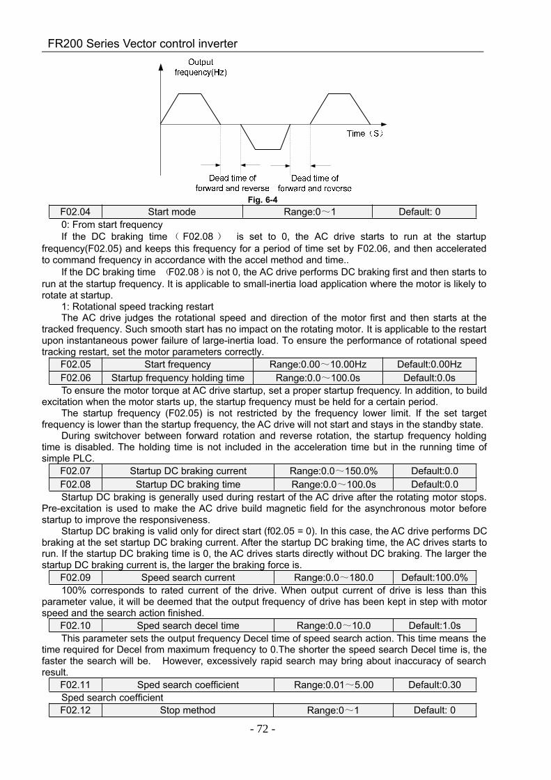
FR200 Series Vector control inverter
- 72 -
Fig. 6-4F02.04 Start mode Range:0~1 Default: 00: From start frequencyIf the DC braking time ( F02.08 ) is set to 0, the AC drive starts to run at the startup
frequency(F02.05) and keeps this frequency for a period of time set by F02.06, and then acceleratedto command frequency in accordance with the accel method and time..
If the DC braking time (F02.08)is not 0, the AC drive performs DC braking first and then starts torun at the startup frequency. It is applicable to small-inertia load application where the motor is likely torotate at startup.
1: Rotational speed tracking restartThe AC drive judges the rotational speed and direction of the motor first and then starts at the
tracked frequency. Such smooth start has no impact on the rotating motor. It is applicable to the restartupon instantaneous power failure of large-inertia load. To ensure the performance of rotational speedtracking restart, set the motor parameters correctly.
F02.05 Start frequency Range:0.00~10.00Hz Default:0.00HzF02.06 Startup frequency holding time Range:0.0~100.0s Default:0.0sTo ensure the motor torque at AC drive startup, set a proper startup frequency. In addition, to build
excitation when the motor starts up, the startup frequency must be held for a certain period.The startup frequency (F02.05) is not restricted by the frequency lower limit. If the set target
frequency is lower than the startup frequency, the AC drive will not start and stays in the standby state.During switchover between forward rotation and reverse rotation, the startup frequency holding
time is disabled. The holding time is not included in the acceleration time but in the running time ofsimple PLC.
F02.07 Startup DC braking current Range:0.0~150.0% Default:0.0F02.08 Startup DC braking time Range:0.0~100.0s Default:0.0Startup DC braking is generally used during restart of the AC drive after the rotating motor stops.
Pre-excitation is used to make the AC drive build magnetic field for the asynchronous motor beforestartup to improve the responsiveness.
Startup DC braking is valid only for direct start (f02.05 = 0). In this case, the AC drive performs DCbraking at the set startup DC braking current. After the startup DC braking time, the AC drives starts torun. If the startup DC braking time is 0, the AC drives starts directly without DC braking. The larger thestartup DC braking current is, the larger the braking force is.
F02.09 Speed search current Range:0.0~180.0 Default:100.0%100% corresponds to rated current of the drive. When output current of drive is less than this
parameter value, it will be deemed that the output frequency of drive has been kept in step with motorspeed and the search action finished.
F02.10 Sped search decel time Range:0.0~10.0 Default:1.0sThis parameter sets the output frequency Decel time of speed search action. This time means the
time required for Decel from maximum frequency to 0.The shorter the speed search Decel time is, thefaster the search will be. However, excessively rapid search may bring about inaccuracy of searchresult.
F02.11 Sped search coefficient Range:0.01~5.00 Default:0.30Sped search coefficientF02.12 Stop method Range:0~1 Default: 0
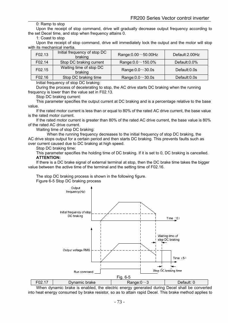
FR200 Series Vector control inverter
- 73 -
0: Ramp to stopUpon the receipt of stop command, drive will gradually decrease output frequency according to
the set Decel time, and stop when frequency attains 0.1: Coast to stopUpon the receipt of stop command, drive will immediately lock the output and the motor will stop
with its mechanical inertia.
F02.13 Initial frequency of stop DCbraking Range:0.00~50.00Hz Default:2.00Hz
F02.14 Stop DC braking current Range:0.0~150.0% Default:0.0%
F02.15 Waiting time of stop DCbraking Range:0.0~30.0s Default:0.0s
F02.16 Stop DC braking time Range:0.0~30.0s Default:0.0sInitial frequency of stop DC braking:During the process of decelerating to stop, the AC drive starts DC braking when the running
frequency is lower than the value set in F02.13.Stop DC braking current:This parameter specifies the output current at DC braking and is a percentage relative to the base
value.If the rated motor current is less than or equal to 80% of the rated AC drive current, the base value
is the rated motor current.If the rated motor current is greater than 80% of the rated AC drive current, the base value is 80%
of the rated AC drive current.Waiting time of stop DC braking:
When the running frequency decreases to the initial frequency of stop DC braking, theAC drive stops output for a certain period and then starts DC braking. This prevents faults such asover current caused due to DC braking at high speed.
Stop DC braking time:This parameter specifies the holding time of DC braking. If it is set to 0, DC braking is cancelled.ATTENTION:If there is a DC brake signal of external terminal at stop, then the DC brake time takes the bigger
value between the active time of the terminal and the setting time of F02.16.
The stop DC braking process is shown in the following figure.Figure 6-5 Stop DC braking process
Fig. 6-5F02.17 Dynamic brake Range:0~3 Default: 0When dynamic brake is enabled, the electric energy generated during Decel shall be converted
into heat energy consumed by brake resistor, so as to attain rapid Decel. This brake method applies to
FR200 Series Vector control inverter
- 74 -
brake of high-inertia load or the situations that require quick stop. In such a case, it is necessary toselect appropriate dynamic brake resistor and break unit. The AC drives equal and below 30kW isprovided with a standard built-in brake unit. Built-in brake unit is optional for AC drive 37kW~75kW.
0: Disabled1: Enabled2: Enabled at running3: Enabled at deceleration
F02.18 Dynamic brake thresholdvoltage Range:90.0~150.0% Default:128.0%
This parameter takes effect only to the drives with built-in brake unit.When bus voltage of AC drive attains the value of F02.18, dynamic brake shall perform. The
energy shall be rapidly consumed through brake resistor. This value is used to regulate the brakeeffect of brake unit.
F02.19 Brake use ratio Range:5.0~100.0% Default:100.0%It is valid only for the AC drive with internal braking unit and used to adjust the duty ratio of the
braking unit. The larger the value of this parameter is, the better the braking result will be. However,too larger value causes great fluctuation of the AC drive bus voltage during the braking process.Group F03 Accel/Decel Parameters
F03.00 Accel time 1 Range:0.0~6000.0s Default:15.0sF03.01 Decel time 1 Range:0.0~6000.0s Default:15.0sF03.02 Accel time 2 Range:0.0~6000.0s Default:15.0sF03.03 Decel time 2 Range:0.0~6000.0s Default:15.0sF03.04 Accel time 3 Range:0.0~6000.0s Default:15.0sF03.05 Decel time 3 Range:0.0~6000.0s Default:15.0sF03.06 Accel time 4 Range:0.0~6000.0s Default:15.0sF03.07 Decel time 4 Range:0.0~6000.0s Default:15.0sAccel time means required time for drive to Accelerate to maximum frequency F01.08 from zero
frequency, while Decel time refers to the time required for drive to Decelerate to zero frequency frommaximum frequency F01.08.
These four types of Accel/Decel time can be selected through the ON/OFF combination ofDI terminals" Accel/Decel time determinant 1" and "Accel/Decel time determinant 2". See the followingtable.
Accel/Decel timedeterminant 2
Accel/Decel timedeterminant 1 Accel/Decel time
OFF OFF Accel/Decel time 1(F03.00、F03.01)OFF ON Accel/Decel time 2(F03.02、F03.03)ON OFF Accel/Decel time 3(F03.04、F03.05)ON ON Accel/Decel time 4(F03.06、F03.07)
F03.08 Jog accel time Range:0.0~6000.0s Default:15.0sF03.09 Jog decel time Range:0.0~6000.0s Default:15.0s
F03.08 and F03.09 set the rate of Accel/Decel of Jog, similar with F03.00~F03.07.F03.10 Accel/Decele curve Range:0~1 Default: 0F03.11 S curve Time 1 Range:0.0~6000.0s Default:0.0sF03.15 S curve Time 2 Range:0.0~6000.0s Default:0.0sF03.16 S curve Time 3 Range:0.0~6000.0s Default:0.0sF03.17 S curve Time 4 Range:0.0~6000.0s Default:0.0s
0: Linear Accel/DecelAccel/Decel is in linear mode.1: S-curve Accel/DecelThe 1st section and the last section in accelerating or decelerating are in smooth transition. Theacceleration/deceleration curve is similar to S curve. When it is in S curve, the finalacceleration/deceleration time= S curve time+ Linear acceleration/deceleration time. See Figure 6-13for 2 acceleration/deceleration modes.
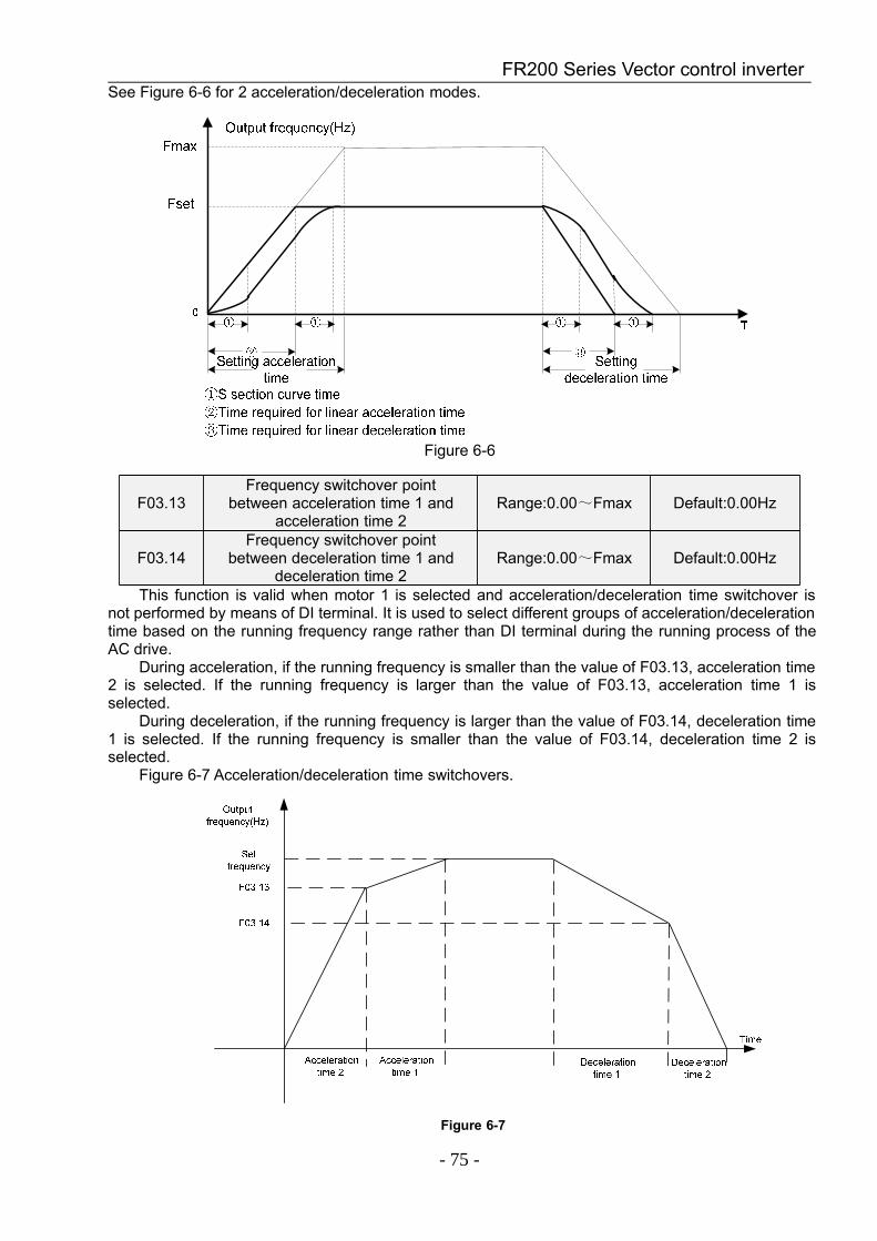
FR200 Series Vector control inverter
- 75 -
See Figure 6-6 for 2 acceleration/deceleration modes.
Figure 6-6
F03.13Frequency switchover point
between acceleration time 1 andacceleration time 2
Range:0.00~Fmax Default:0.00Hz
F03.14Frequency switchover point
between deceleration time 1 anddeceleration time 2
Range:0.00~Fmax Default:0.00Hz
This function is valid when motor 1 is selected and acceleration/deceleration time switchover isnot performed by means of DI terminal. It is used to select different groups of acceleration/decelerationtime based on the running frequency range rather than DI terminal during the running process of theAC drive.
During acceleration, if the running frequency is smaller than the value of F03.13, acceleration time2 is selected. If the running frequency is larger than the value of F03.13, acceleration time 1 isselected.
During deceleration, if the running frequency is larger than the value of F03.14, deceleration time1 is selected. If the running frequency is smaller than the value of F03.14, deceleration time 2 isselected.
Figure 6-7 Acceleration/deceleration time switchovers.
Figure 6-7

FR200 Series Vector control inverter
- 76 -
Group F04 Digital InputF04.00 Function of terminal DI1 Range:0~99 Default:1F04.01 Function of terminal DI2 Range:0~99 Default:2F04.02 Function of terminal DI3 Range:0~99 Default:7F04.03 Function of terminal DI4 Range:0~99 Default:13F04.04 Function of terminal DI5 Range:0~99 Default:0F04.05 Function of terminal DI6 Range:0~99 Default:0F04.06 Function of terminal DI7 Range:0~99 Default:0
Value Function escription0 No function Set 0 for reserved terminals to avoid malfunction.
1 Forward RUN(FWD) Terminals control forward running and reverse running of the
drive. Refer to F04.15 for enabled conditions on initial powerup.2 Reverse RUN
(REV)
3 Three-wire control The terminal determines three-line control of the AC drive. Fordetails, see the description of F04.15.
4 Forward JOG(FJOG)
FJOG indicates forward JOG running, while RJOG indicatesreverse JOG running. The JOG frequency, acceleration timeand deceleration time are described respectively in F01.07,F03.08 and F03.09.5 Reverse JOG
(RJOG)
6 Coast to stopThe AC drive blocks its output, the motor coasts to rest and isnot controlled by the AC drive. It is the same as coast to stopdescribed in F02.12.
7 Fault reset (RESET)The terminal is used for fault reset function, the same as thefunction of RESET key on the operation panel.Remote faultreset is implemented by this function.
8 RUN pause
The AC drive decelerates to stop, but the running parametersare all memorized, such as PLC, swing frequency and PIDparameters. After this function is disabled, the AC driveresumes its status before stop.
9Normally open (NO)
inputof external fault
If this terminal becomes ON, the AC drive reports Err13 andperforms the fault protection action. For more details, see thedescription of F11.11.
10 Terminal UP If the frequency is determined by external terminals, theTerminals with the two functions are used as increment anddecrement commands for frequency modification.11 Terminal DOWN
12
UP and DOWNsetting
clear (terminal,keypad)
If the frequency source is master frequency source setting, theterminalis used to clear the modification by using theUP/DOWN function or the increment/decrement key on thekeypad, returning the set frequency to the value of masterfrequency source setting.
13 Multi-referenceterminal 1
The setting of 16 speeds or 16 other references can beimplemented through combinations of 16 states of these fourterminals.
14 Multi-referenceterminal 2
15 Multi-referenceterminal 3
16 Multi-referenceterminal 4
17
Terminal 1 foracceleration/
deceleration timeselection
Totally four groups of acceleration/deceleration time can beselected through combinations of two states of these twoterminals.
18 Terminal 2 foracceleration/
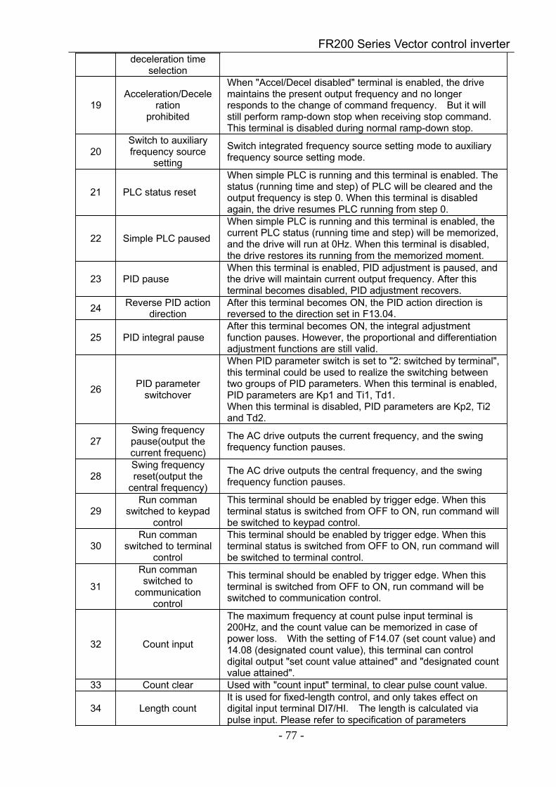
FR200 Series Vector control inverter
- 77 -
deceleration timeselection
19Acceleration/Decele
rationprohibited
When "Accel/Decel disabled" terminal is enabled, the drivemaintains the present output frequency and no longerresponds to the change of command frequency. But it willstill perform ramp-down stop when receiving stop command.This terminal is disabled during normal ramp-down stop.
20Switch to auxiliaryfrequency source
setting
Switch integrated frequency source setting mode to auxiliaryfrequency source setting mode.
21 PLC status reset
When simple PLC is running and this terminal is enabled. Thestatus (running time and step) of PLC will be cleared and theoutput frequency is step 0. When this terminal is disabledagain, the drive resumes PLC running from step 0.
22 Simple PLC paused
When simple PLC is running and this terminal is enabled, thecurrent PLC status (running time and step) will be memorized,and the drive will run at 0Hz. When this terminal is disabled,the drive restores its running from the memorized moment.
23 PID pauseWhen this terminal is enabled, PID adjustment is paused, andthe drive will maintain current output frequency. After thisterminal becomes disabled, PID adjustment recovers.
24 Reverse PID actiondirection
After this terminal becomes ON, the PID action direction isreversed to the direction set in F13.04.
25 PID integral pauseAfter this terminal becomes ON, the integral adjustmentfunction pauses. However, the proportional and differentiationadjustment functions are still valid.
26 PID parameterswitchover
When PID parameter switch is set to "2: switched by terminal",this terminal could be used to realize the switching betweentwo groups of PID parameters. When this terminal is enabled,PID parameters are Kp1 and Ti1, Td1.When this terminal is disabled, PID parameters are Kp2, Ti2and Td2.
27Swing frequencypause(output thecurrent frequenc)
The AC drive outputs the current frequency, and the swingfrequency function pauses.
28Swing frequencyreset(output the
central frequency)
The AC drive outputs the central frequency, and the swingfrequency function pauses.
29Run comman
switched to keypadcontrol
This terminal should be enabled by trigger edge. When thisterminal status is switched from OFF to ON, run command willbe switched to keypad control.
30Run comman
switched to terminalcontrol
This terminal should be enabled by trigger edge. When thisterminal status is switched from OFF to ON, run command willbe switched to terminal control.
31
Run commanswitched to
communicationcontrol
This terminal should be enabled by trigger edge. When thisterminal is switched from OFF to ON, run command will beswitched to communication control.
32 Count input
The maximum frequency at count pulse input terminal is200Hz, and the count value can be memorized in case ofpower loss. With the setting of F14.07 (set count value) and14.08 (designated count value), this terminal can controldigital output "set count value attained" and "designated countvalue attained".
33 Count clear Used with "count input" terminal, to clear pulse count value.
34 Length countIt is used for fixed-length control, and only takes effect ondigital input terminal DI7/HI. The length is calculated viapulse input. Please refer to specification of parameters
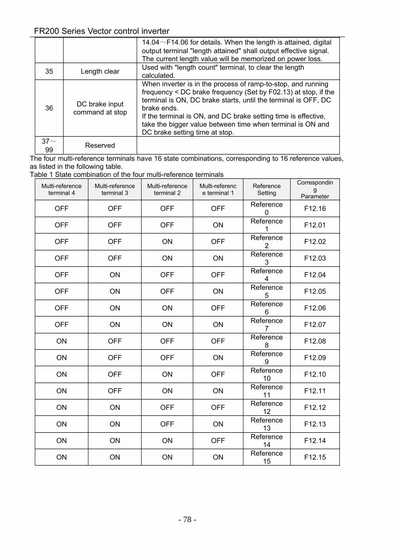
FR200 Series Vector control inverter
- 78 -
14.04~F14.06 for details. When the length is attained, digitaloutput terminal "length attained" shall output effective signal.The current length value will be memorized on power loss.
35 Length clear Used with "length count" terminal, to clear the lengthcalculated.
36 DC brake inputcommand at stop
When inverter is in the process of ramp-to-stop, and runningfrequency < DC brake frequency (Set by F02.13) at stop, if theterminal is ON, DC brake starts, until the terminal is OFF, DCbrake ends.If the terminal is ON, and DC brake setting time is effective,take the bigger value between time when terminal is ON andDC brake setting time at stop.
37~99 Reserved
The four multi-reference terminals have 16 state combinations, corresponding to 16 reference values,as listed in the following table.Table 1 State combination of the four multi-reference terminals
Multi-referenceterminal 4
Multi-referenceterminal 3
Multi-referenceterminal 2
Multi-reference terminal 1
ReferenceSetting
Corresponding
Parameter
OFF OFF OFF OFF Reference0 F12.16
OFF OFF OFF ON Reference1 F12.01
OFF OFF ON OFF Reference2 F12.02
OFF OFF ON ON Reference3 F12.03
OFF ON OFF OFF Reference4 F12.04
OFF ON OFF ON Reference5 F12.05
OFF ON ON OFF Reference6 F12.06
OFF ON ON ON Reference7 F12.07
ON OFF OFF OFF Reference8 F12.08
ON OFF OFF ON Reference9 F12.09
ON OFF ON OFF Reference10 F12.10
ON OFF ON ON Reference11 F12.11
ON ON OFF OFF Reference12 F12.12
ON ON OFF ON Reference13 F12.13
ON ON ON OFF Reference14 F12.14
ON ON ON ON Reference15 F12.15
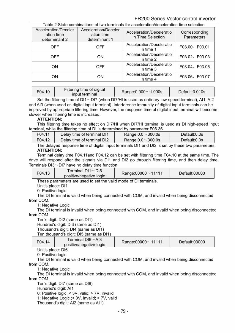
FR200 Series Vector control inverter
- 79 -
Table 2 State combinations of two terminals for acceleration/deceleration time selectionAcceleration/Deceler
ation timedeterminant 2
Acceleration/Deceleration time
determinant 1
Acceleration/Deceleration Time Selection
CorrespondingParameters
OFF OFF Acceleration/Deceleration time 1 F03.00、F03.01
OFF ON Acceleration/Deceleration time 2 F03.02、F03.03
ON OFF Acceleration/Deceleration time 3 F03.04、F03.05
ON ON Acceleration/Deceleration time 4 F03.06、F03.07
F04.10 Filtering time of digitalinput terminal Range:0.000~1.000s Default:0.010s
Set the filtering time of DI1~DI7 (when DI7/HI is used as ordinary low-speed terminal), AI1, AI2and AI3 (when used as digital input terminal). Interference immunity of digital input terminals can beimproved by appropriate filtering time. However, the response time of digital input terminal will becomeslower when filtering time is increased.
ATTENTION:This filtering time takes no effect on DI7/HI when DI7/HI terminal is used as DI high-speed input
terminal, while the filtering time of DI is determined by parameter F06.36.F04.11 Delay time of terminal DI1 Range:0.0~300.0s Default:0.0sF04.12 Delay time of terminal DI2 Range:0.0~300.0s Default:0.0sThe delayed response time of digital input terminals DI1 and DI2 is set by these two parameters.ATTENTION:Terminal delay time F04.11and F04.12 can be set with filtering time F04.10 at the same time. The
drive will respond after the signals via DI1 and DI2 go through filtering time, and then delay time.Terminals DI3~DI7 have no delay time function.
F04.13 Terminal DI1~DI5positive/negative logic Range:00000~11111 Default:00000
These parameters are used to set the valid mode of DI terminals.Unit's place: DI10: Positive logicThe DI terminal is valid when being connected with COM, and invalid when being disconnected
from COM.1: Negative LogicThe DI terminal is invalid when being connected with COM, and invalid when being disconnected
from COM.Ten's digit: DI2 (same as DI1)Hundred's digit: DI3 (same as DI1)Thousand's digit: DI4 (same as DI1)Ten thousand's digit: DI5 (same as DI1)
F04.14 Terminal DI6~AI3positive/negative logic Range:00000~11111 Default:00000
Unit's place: DI60: Positive logicThe DI terminal is valid when being connected with COM, and invalid when being disconnected
from COM.1: Negative LogicThe DI terminal is invalid when being connected with COM, and invalid when being disconnected
from COM.Ten's digit: DI7 (same as DI6)Hundred's digit: AI10: Positive logic ;< 3V, valid; > 7V, invalid1: Negative Logic ;< 3V, invalid; > 7V, validThousand's digit: AI2 (same as AI1)
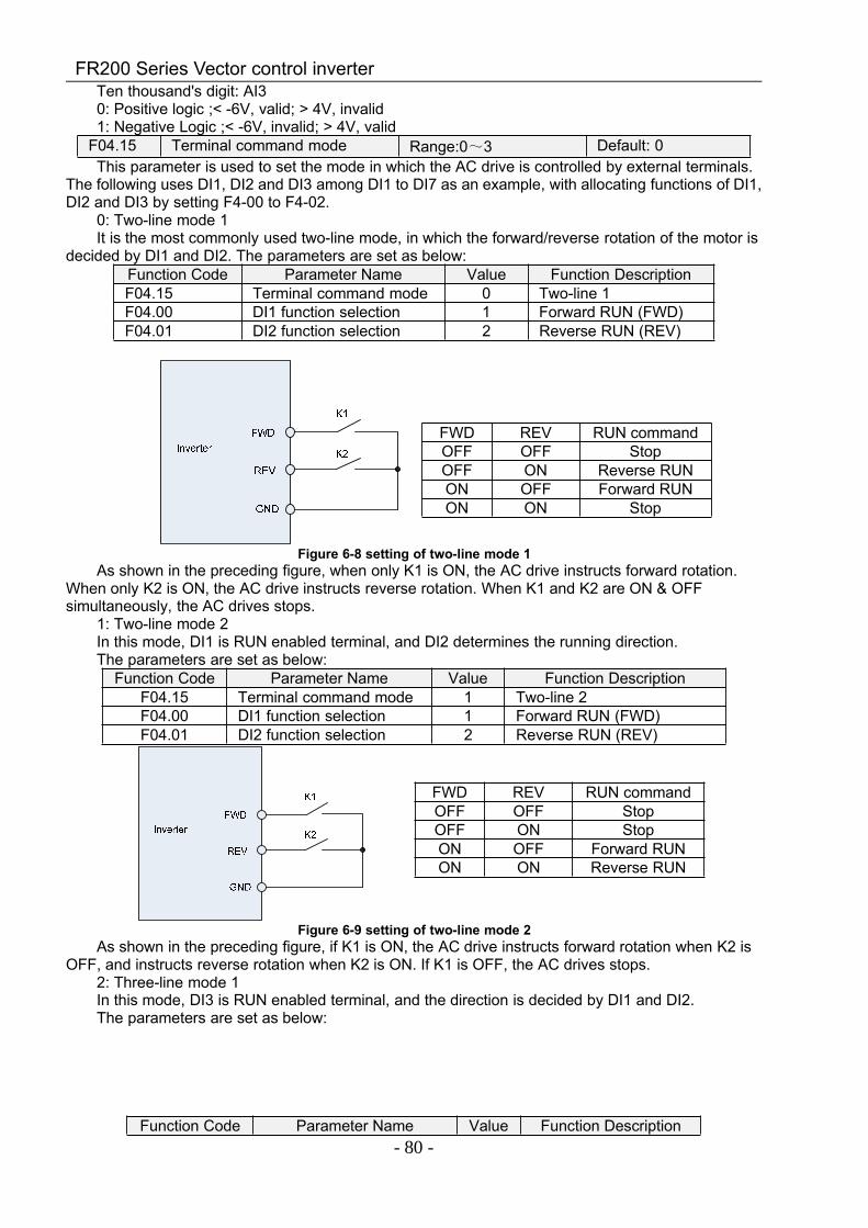
FR200 Series Vector control inverter
- 80 -
Ten thousand's digit: AI30: Positive logic ;< -6V, valid; > 4V, invalid1: Negative Logic ;< -6V, invalid; > 4V, valid
F04.15 Terminal command mode Range:0~3 Default: 0This parameter is used to set the mode in which the AC drive is controlled by external terminals.
The following uses DI1, DI2 and DI3 among DI1 to DI7 as an example, with allocating functions of DI1,DI2 and DI3 by setting F4-00 to F4-02.
0: Two-line mode 1It is the most commonly used two-line mode, in which the forward/reverse rotation of the motor is
decided by DI1 and DI2. The parameters are set as below:Function Code Parameter Name Value Function DescriptionF04.15 Terminal command mode 0 Two-line 1F04.00 DI1 function selection 1 Forward RUN (FWD)F04.01 DI2 function selection 2 Reverse RUN (REV)
Figure 6-8 setting of two-line mode 1As shown in the preceding figure, when only K1 is ON, the AC drive instructs forward rotation.
When only K2 is ON, the AC drive instructs reverse rotation. When K1 and K2 are ON & OFFsimultaneously, the AC drives stops.
1: Two-line mode 2In this mode, DI1 is RUN enabled terminal, and DI2 determines the running direction.The parameters are set as below:
Function Code Parameter Name Value Function DescriptionF04.15 Terminal command mode 1 Two-line 2F04.00 DI1 function selection 1 Forward RUN (FWD)F04.01 DI2 function selection 2 Reverse RUN (REV)
Figure 6-9 setting of two-line mode 2As shown in the preceding figure, if K1 is ON, the AC drive instructs forward rotation when K2 is
OFF, and instructs reverse rotation when K2 is ON. If K1 is OFF, the AC drives stops.2: Three-line mode 1In this mode, DI3 is RUN enabled terminal, and the direction is decided by DI1 and DI2.The parameters are set as below:
Function Code Parameter Name Value Function Description
FWD REV RUN commandOFF OFF StopOFF ON Reverse RUNON OFF Forward RUNON ON Stop
FWD REV RUN commandOFF OFF StopOFF ON StopON OFF Forward RUNON ON Reverse RUN
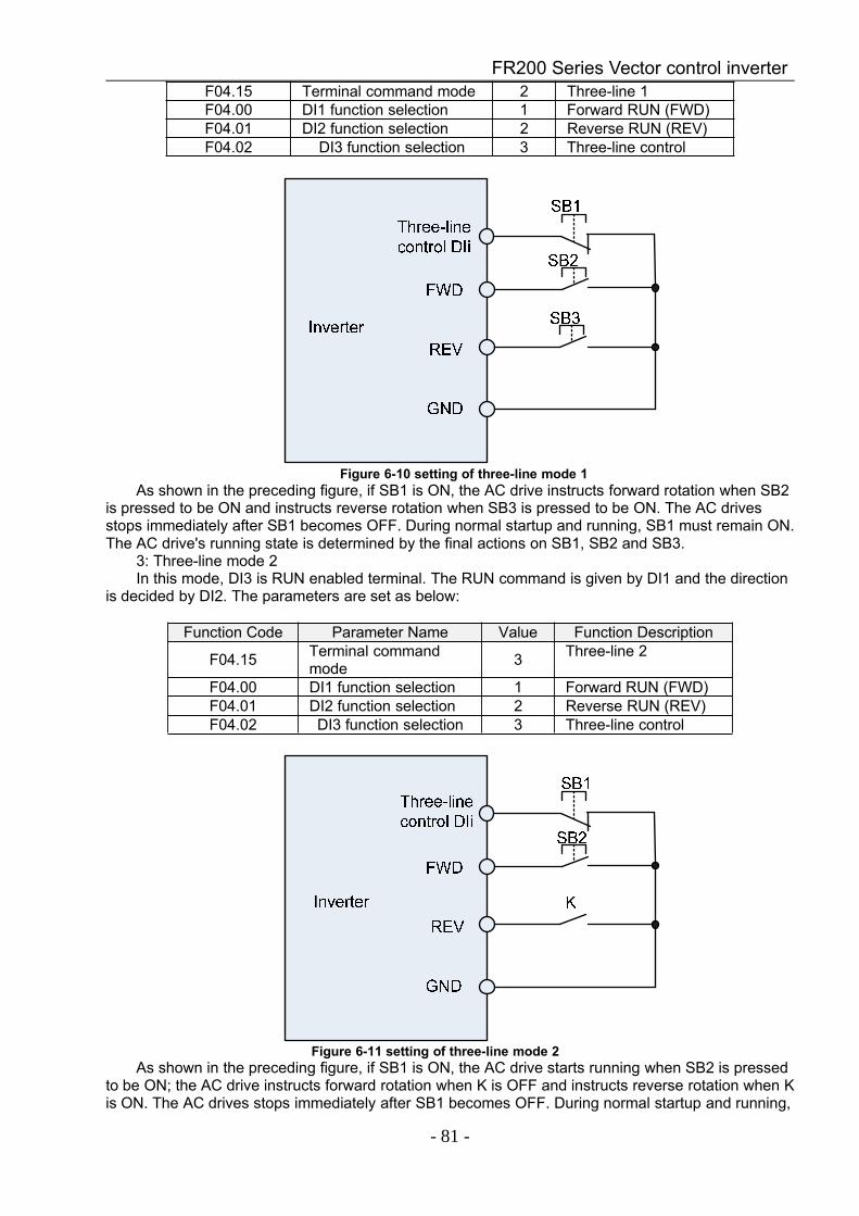
FR200 Series Vector control inverter
- 81 -
F04.15 Terminal command mode 2 Three-line 1F04.00 DI1 function selection 1 Forward RUN (FWD)F04.01 DI2 function selection 2 Reverse RUN (REV)F04.02 DI3 function selection 3 Three-line control
Figure 6-10 setting of three-line mode 1As shown in the preceding figure, if SB1 is ON, the AC drive instructs forward rotation when SB2
is pressed to be ON and instructs reverse rotation when SB3 is pressed to be ON. The AC drivesstops immediately after SB1 becomes OFF. During normal startup and running, SB1 must remain ON.The AC drive's running state is determined by the final actions on SB1, SB2 and SB3.
3: Three-line mode 2In this mode, DI3 is RUN enabled terminal. The RUN command is given by DI1 and the direction
is decided by DI2. The parameters are set as below:
Function Code Parameter Name Value Function Description
F04.15 Terminal commandmode 3 Three-line 2
F04.00 DI1 function selection 1 Forward RUN (FWD)F04.01 DI2 function selection 2 Reverse RUN (REV)F04.02 DI3 function selection 3 Three-line control
Figure 6-11 setting of three-line mode 2As shown in the preceding figure, if SB1 is ON, the AC drive starts running when SB2 is pressed
to be ON; the AC drive instructs forward rotation when K is OFF and instructs reverse rotation when Kis ON. The AC drives stops immediately after SB1 becomes OFF. During normal startup and running,
FR200 Series Vector control inverter
- 82 -
SB1 must remain ON. The AC drive's running state is determined by the final actions of SB1, SB2 andK.
F04.16 Terminal UP/DOWN frequencyadjustment treatment Range:00~11 Default:00
Unit's place: action when stop0: ClearTerminal UP/DOWN frequency adjustment value is cleared when the drive stops.1: HoldingTerminal UP/DOWN frequency adjustment value is maintained when the drive stops.Ten's digit: action on power loss0: ClearTerminal UP/DOWN frequency adjustment value is cleared in case of power loss.1: HoldingTerminal UP/DOWN frequency adjustment value is saved in case of power loss.Hundred's digit: integral function0: No integral functionAdjustment step size is kept constant during terminal UP/DOWN adjustment, in compliance with
F04.17.1: Integral function enabledWhen frequency is adjusted through terminal UP/DOWN, initial step size is set by F04.17.
With the effective lasting time of the terminals, adjustment step size will increase gradually.
F04.17 Terminal UP/DOWNfrequency change step size Range:0.00~50.00Hz Default:1.00Hz/200ms
It is used to adjust the rate of change of frequency when the frequency is adjusted by means ofterminal UP/DOWN.Group F05 Digital Output
F05.00 Y1 output function Range:0~99 Default:1
F05.01 Y2/HO output function(when used as Y2) Range:0~99 Default:3
F05.02 Relay 1 output function Range:0~99 Default:2F05.03 Relay 2 output function Range:0~99 Default:11
Define the functions of digital output terminals Y1 & Y2, relay 1 and relay 2.Output terminalfunction selections are as follows:
Setting
Correspondingfunction Description
0 No output Output terminal is disabled, and there is no output.
1 Drive is running The output is ON when the drive is running, and output isOFF when drive stopped.
2 Fault output When the drive is in fault, outputs ON.
3 Frequency-leveldetection FDT1 output Refer to the descriptions of F05.10 and F05.11.
4 Frequency-leveldetection FDT2 output Refer to the descriptions of F05.12 and F05.13.
5 Drive in 0Hz running1(no output at stop)
When be running at 0Hz, this corresponding terminaloutputs ON signal. No ON signal will be output at stop.
6 Drive in 0Hz running2(output at stop)
Outputs ON signal when is running at 0Hz and also outputsON signal at stop.
7 Upper limit frequencyattained
When output frequency attains F01.09 (upper limitfrequency), outputs ON.
8Lower limit frequencyattained (no output at
stop)
When output frequency attains F01.10 (lower limitfrequency), outputs ON. In the stop state, the terminalbecomes OFF.
9 Frequency attained Refer to the descriptions of F05.09.
10 Ready for RUNIf the AC drive main circuit and control circuit becomestable, and the AC drive detects no fault and is ready forRUN, the terminal becomes ON.
FR200 Series Vector control inverter
- 83 -
11 Drive (motor)overloaded alarm
In case drive output current exceeds F11.19 (overloadalarm threshold) and its last time exceeds F11.20 (overloadalarm activated time that exceeding threshold), outputs ON.Refer to parameters F11.18~ F11.20 for information withregard to drive (motor) overloaded alarm.
12 Drive overheat alarm When drive internally detected temperature exceeds F11.21(Drive overheat alarm threshold), ON signal will be output.
13 Current running timeattained
When current running time attains the value of F05.14,corresponding terminal outputs ON. Current running time iscleared when stop.
14Accumulativepower-on time
attained
When accumulative power-on time attains the value ofF05.15, corresponding terminal outputs ON. Accumulativepower-on time is maintained when stop.
15 Accumulative runningtime attained
When accumulative running time attains the value ofF05.16, corresponding terminal outputs ON. Accumulativerunning time is maintained when stop.
16 PLC cycle completed Upon the completion of a cycle of simple PLC running, ONsignal with a width of 250ms will be output.
17 Set count valueattained
The terminal becomes ON when the count value reachesthe value set in F14.07.
18 Designated countvalue attained
The terminal becomes ON when the count value reachesthe value set in F14.08. Refer to the specification ofparameter F14.07 and F14.08.
19 Length attainedThe terminal becomes ON when the detected actual lengthexceeds the value set in F14.04. Refer to the specificationof parameter F14.05~F14.07.
20~99 Reserved
F05.04 Y1 output delay time Range:0.0~6000.0s Default:0.0sF05.05 Y2 output delay time Range:0.0~6000.0s Default:0.0sF05.06 Relay 1 output delay time Range:0.0~6000.0s Default:0.0sF05.07 Relay 2 output delay time Range:0.0~6000.0s Default:0.0sThese four parameters define the delay response time of digital output terminals Y1 & Y2, relay 1
and relay 2.
F05.08 Enabled state of digitaloutput Range:0000~1111 Default:0000
Unit's place: Y10: Positive logic; ON when current passes through1: Negative logic; ON when no current passes through
Decade: Y2 (same as Y1) Hundreds place: relay 1 output
0: Positive logic; ON when there is coil excitation1: Negative logic; ON when there is no coil excitation
Thousands place: relay 2 output (same as relay 1)Wiring diagram of digital output terminal is shown as Fig. 6-12:
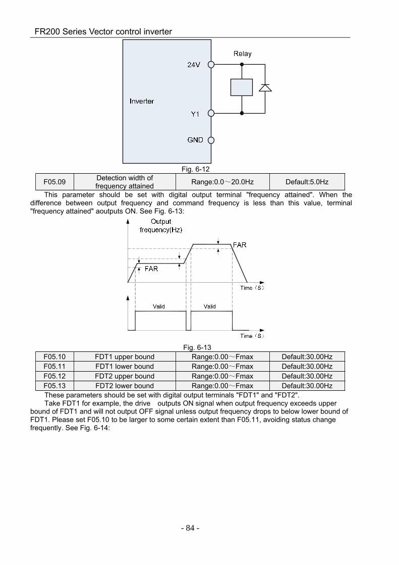
FR200 Series Vector control inverter
- 84 -
Fig. 6-12
F05.09 Detection width offrequency attained Range:0.0~20.0Hz Default:5.0Hz
This parameter should be set with digital output terminal "frequency attained". When thedifference between output frequency and command frequency is less than this value, terminal"frequency attained" aoutputs ON. See Fig. 6-13:
Fig. 6-13F05.10 FDT1 upper bound Range:0.00~Fmax Default:30.00HzF05.11 FDT1 lower bound Range:0.00~Fmax Default:30.00HzF05.12 FDT2 upper bound Range:0.00~Fmax Default:30.00HzF05.13 FDT2 lower bound Range:0.00~Fmax Default:30.00HzThese parameters should be set with digital output terminals "FDT1" and "FDT2".Take FDT1 for example, the drive outputs ON signal when output frequency exceeds upper
bound of FDT1 and will not output OFF signal unless output frequency drops to below lower bound ofFDT1. Please set F05.10 to be larger to some certain extent than F05.11, avoiding status changefrequently. See Fig. 6-14:
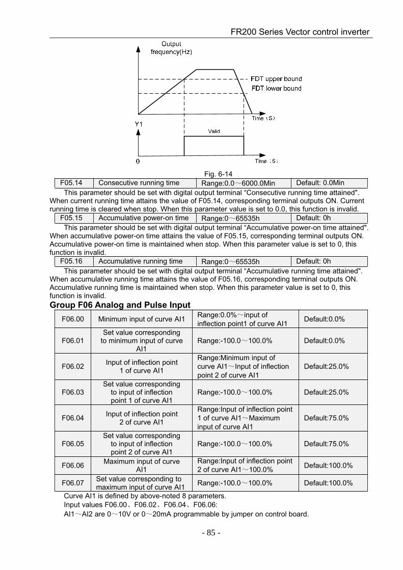
FR200 Series Vector control inverter
- 85 -
Fig. 6-14F05.14 Consecutive running time Range:0.0~6000.0Min Default: 0.0MinThis parameter should be set with digital output terminal “Consecutive running time attained".
When current running time attains the value of F05.14, corresponding terminal outputs ON. Currentrunning time is cleared when stop. When this parameter value is set to 0.0, this function is invalid.
F05.15 Accumulative power-on time Range:0~65535h Default: 0hThis parameter should be set with digital output terminal “Accumulative power-on time attained".
When accumulative power-on time attains the value of F05.15, corresponding terminal outputs ON.Accumulative power-on time is maintained when stop. When this parameter value is set to 0, thisfunction is invalid.
F05.16 Accumulative running time Range:0~65535h Default: 0hThis parameter should be set with digital output terminal “Accumulative running time attained".
When accumulative running time attains the value of F05.16, corresponding terminal outputs ON.Accumulative running time is maintained when stop. When this parameter value is set to 0, thisfunction is invalid.Group F06 Analog and Pulse Input
F06.00 Minimum input of curve AI1 Range:0.0%~input ofinflection point1 of curve AI1 Default:0.0%
F06.01Set value corresponding
to minimum input of curveAI1
Range:-100.0~100.0% Default:0.0%
F06.02 Input of inflection point1 of curve AI1
Range:Minimum input ofcurve AI1~Input of inflectionpoint 2 of curve AI1
Default:25.0%
F06.03Set value corresponding
to input of inflectionpoint 1 of curve AI1
Range:-100.0~100.0% Default:25.0%
F06.04 Input of inflection point2 of curve AI1
Range:Input of inflection point1 of curve AI1~Maximuminput of curve AI1
Default:75.0%
F06.05Set value corresponding
to input of inflectionpoint 2 of curve AI1
Range:-100.0~100.0% Default:75.0%
F06.06 Maximum input of curveAI1
Range:Input of inflection point2 of curve AI1~100.0% Default:100.0%
F06.07 Set value corresponding tomaximum input of curve AI1 Range:-100.0~100.0% Default:100.0%
Curve AI1 is defined by above-noted 8 parameters.Input values F06.00、F06.02、F06.04、F06.06:AI1~AI2 are 0~10V or 0~20mA programmable by jumper on control board.
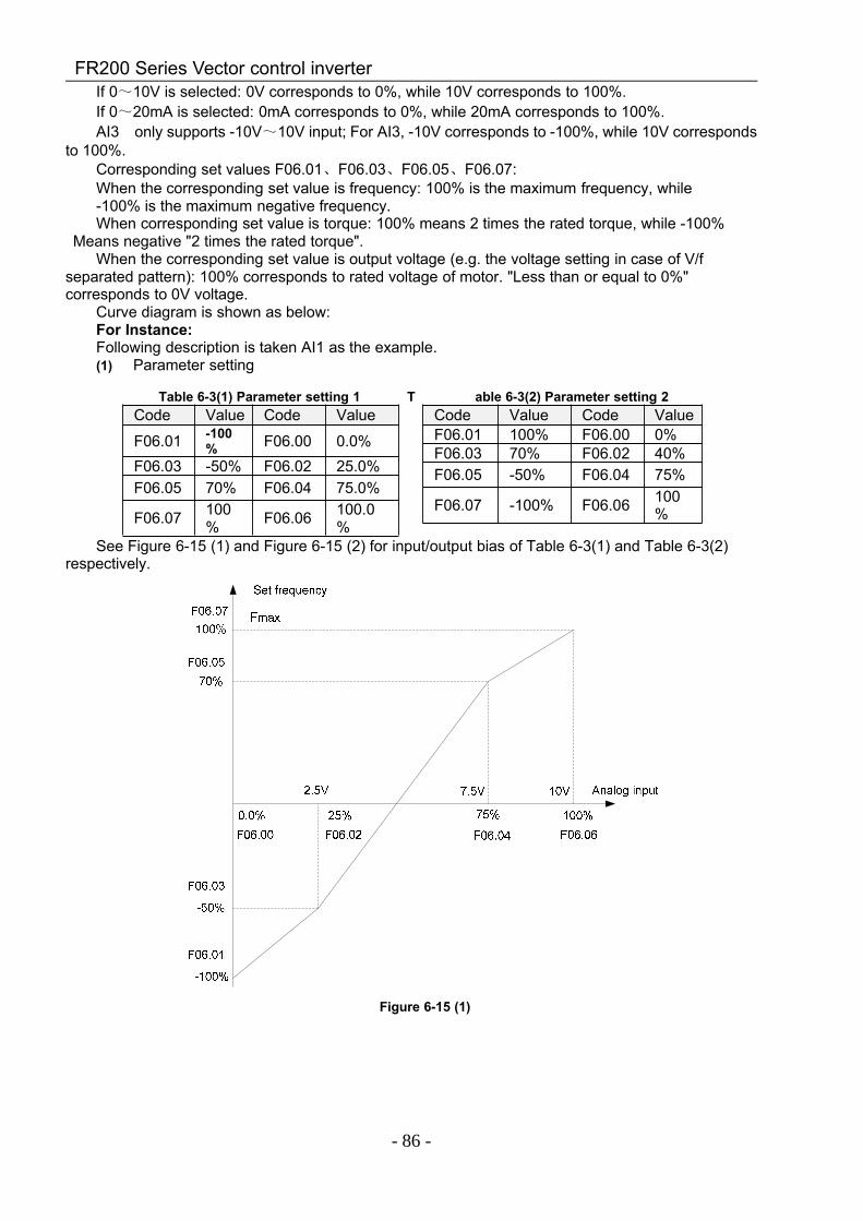
FR200 Series Vector control inverter
- 86 -
If 0~10V is selected: 0V corresponds to 0%, while 10V corresponds to 100%.If 0~20mA is selected: 0mA corresponds to 0%, while 20mA corresponds to 100%.AI3 only supports -10V~10V input; For AI3, -10V corresponds to -100%, while 10V corresponds
to 100%.Corresponding set values F06.01、F06.03、F06.05、F06.07:When the corresponding set value is frequency: 100% is the maximum frequency, while-100% is the maximum negative frequency.When corresponding set value is torque: 100% means 2 times the rated torque, while -100%
Means negative "2 times the rated torque".When the corresponding set value is output voltage (e.g. the voltage setting in case of V/f
separated pattern): 100% corresponds to rated voltage of motor. "Less than or equal to 0%"corresponds to 0V voltage.
Curve diagram is shown as below:For Instance:Following description is taken AI1 as the example.(1) Parameter setting
Table 6-3(1) Parameter setting 1 T able 6-3(2) Parameter setting 2Code Value Code Value
F06.01 -100% F06.00 0.0%
F06.03 -50% F06.02 25.0%F06.05 70% F06.04 75.0%
F06.07 100% F06.06 100.0
%
Code Value Code ValueF06.01 100% F06.00 0%F06.03 70% F06.02 40%F06.05 -50% F06.04 75%
F06.07 -100% F06.06 100%
See Figure 6-15 (1) and Figure 6-15 (2) for input/output bias of Table 6-3(1) and Table 6-3(2)respectively.
Figure 6-15 (1)
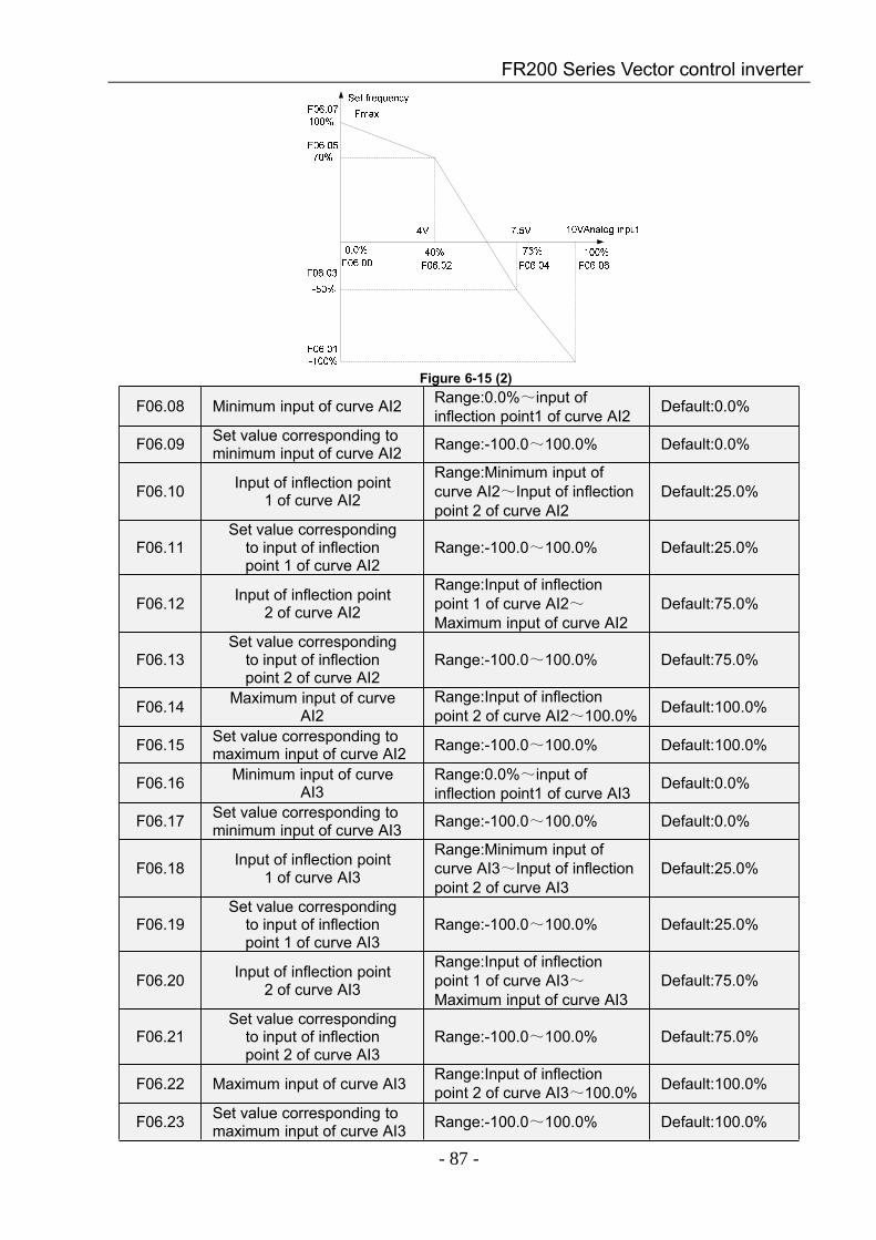
FR200 Series Vector control inverter
- 87 -
Figure 6-15 (2)
F06.08 Minimum input of curve AI2 Range:0.0%~input ofinflection point1 of curve AI2 Default:0.0%
F06.09 Set value corresponding tominimum input of curve AI2 Range:-100.0~100.0% Default:0.0%
F06.10 Input of inflection point1 of curve AI2
Range:Minimum input ofcurve AI2~Input of inflectionpoint 2 of curve AI2
Default:25.0%
F06.11Set value corresponding
to input of inflectionpoint 1 of curve AI2
Range:-100.0~100.0% Default:25.0%
F06.12 Input of inflection point2 of curve AI2
Range:Input of inflectionpoint 1 of curve AI2~Maximum input of curve AI2
Default:75.0%
F06.13Set value corresponding
to input of inflectionpoint 2 of curve AI2
Range:-100.0~100.0% Default:75.0%
F06.14 Maximum input of curveAI2
Range:Input of inflectionpoint 2 of curve AI2~100.0% Default:100.0%
F06.15 Set value corresponding tomaximum input of curve AI2 Range:-100.0~100.0% Default:100.0%
F06.16 Minimum input of curveAI3
Range:0.0%~input ofinflection point1 of curve AI3 Default:0.0%
F06.17 Set value corresponding tominimum input of curve AI3 Range:-100.0~100.0% Default:0.0%
F06.18 Input of inflection point1 of curve AI3
Range:Minimum input ofcurve AI3~Input of inflectionpoint 2 of curve AI3
Default:25.0%
F06.19Set value corresponding
to input of inflectionpoint 1 of curve AI3
Range:-100.0~100.0% Default:25.0%
F06.20 Input of inflection point2 of curve AI3
Range:Input of inflectionpoint 1 of curve AI3~Maximum input of curve AI3
Default:75.0%
F06.21Set value corresponding
to input of inflectionpoint 2 of curve AI3
Range:-100.0~100.0% Default:75.0%
F06.22 Maximum input of curve AI3 Range:Input of inflectionpoint 2 of curve AI3~100.0% Default:100.0%
F06.23 Set value corresponding tomaximum input of curve AI3 Range:-100.0~100.0% Default:100.0%
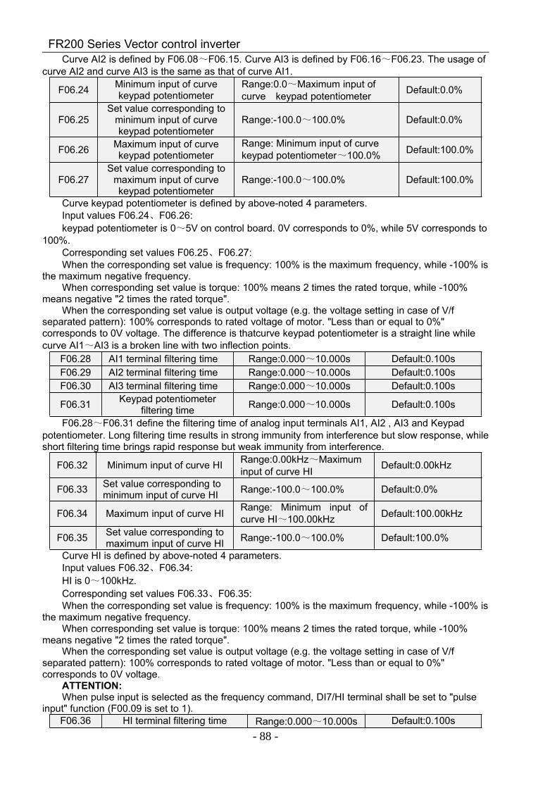
FR200 Series Vector control inverter
- 88 -
Curve AI2 is defined by F06.08~F06.15. Curve AI3 is defined by F06.16~F06.23. The usage ofcurve AI2 and curve AI3 is the same as that of curve AI1.
F06.24 Minimum input of curvekeypad potentiometer
Range:0.0~Maximum input ofcurve keypad potentiometer Default:0.0%
F06.25Set value corresponding to
minimum input of curvekeypad potentiometer
Range:-100.0~100.0% Default:0.0%
F06.26 Maximum input of curvekeypad potentiometer
Range: Minimum input of curvekeypad potentiometer~100.0% Default:100.0%
F06.27Set value corresponding to
maximum input of curvekeypad potentiometer
Range:-100.0~100.0% Default:100.0%
Curve keypad potentiometer is defined by above-noted 4 parameters.Input values F06.24、F06.26:keypad potentiometer is 0~5V on control board. 0V corresponds to 0%, while 5V corresponds to
100%.Corresponding set values F06.25、F06.27:When the corresponding set value is frequency: 100% is the maximum frequency, while -100% is
the maximum negative frequency.When corresponding set value is torque: 100% means 2 times the rated torque, while -100%
means negative "2 times the rated torque".When the corresponding set value is output voltage (e.g. the voltage setting in case of V/f
separated pattern): 100% corresponds to rated voltage of motor. "Less than or equal to 0%"corresponds to 0V voltage. The difference is thatcurve keypad potentiometer is a straight line whilecurve AI1~AI3 is a broken line with two inflection points.
F06.28 AI1 terminal filtering time Range:0.000~10.000s Default:0.100sF06.29 AI2 terminal filtering time Range:0.000~10.000s Default:0.100sF06.30 AI3 terminal filtering time Range:0.000~10.000s Default:0.100s
F06.31 Keypad potentiometerfiltering time Range:0.000~10.000s Default:0.100s
F06.28~F06.31 define the filtering time of analog input terminals AI1, AI2 , AI3 and Keypadpotentiometer. Long filtering time results in strong immunity from interference but slow response, whileshort filtering time brings rapid response but weak immunity from interference.
F06.32 Minimum input of curve HI Range:0.00kHz~Maximuminput of curve HI Default:0.00kHz
F06.33 Set value corresponding tominimum input of curve HI Range:-100.0~100.0% Default:0.0%
F06.34 Maximum input of curve HI Range: Minimum input ofcurve HI~100.00kHz Default:100.00kHz
F06.35 Set value corresponding tomaximum input of curve HI Range:-100.0~100.0% Default:100.0%
Curve HI is defined by above-noted 4 parameters.Input values F06.32、F06.34:HI is 0~100kHz.Corresponding set values F06.33、F06.35:When the corresponding set value is frequency: 100% is the maximum frequency, while -100% is
the maximum negative frequency.When corresponding set value is torque: 100% means 2 times the rated torque, while -100%
means negative "2 times the rated torque".When the corresponding set value is output voltage (e.g. the voltage setting in case of V/f
separated pattern): 100% corresponds to rated voltage of motor. "Less than or equal to 0%"corresponds to 0V voltage.
ATTENTION:When pulse input is selected as the frequency command, DI7/HI terminal shall be set to "pulse
input" function (F00.09 is set to 1).F06.36 HI terminal filtering time Range:0.000~10.000s Default:0.100s
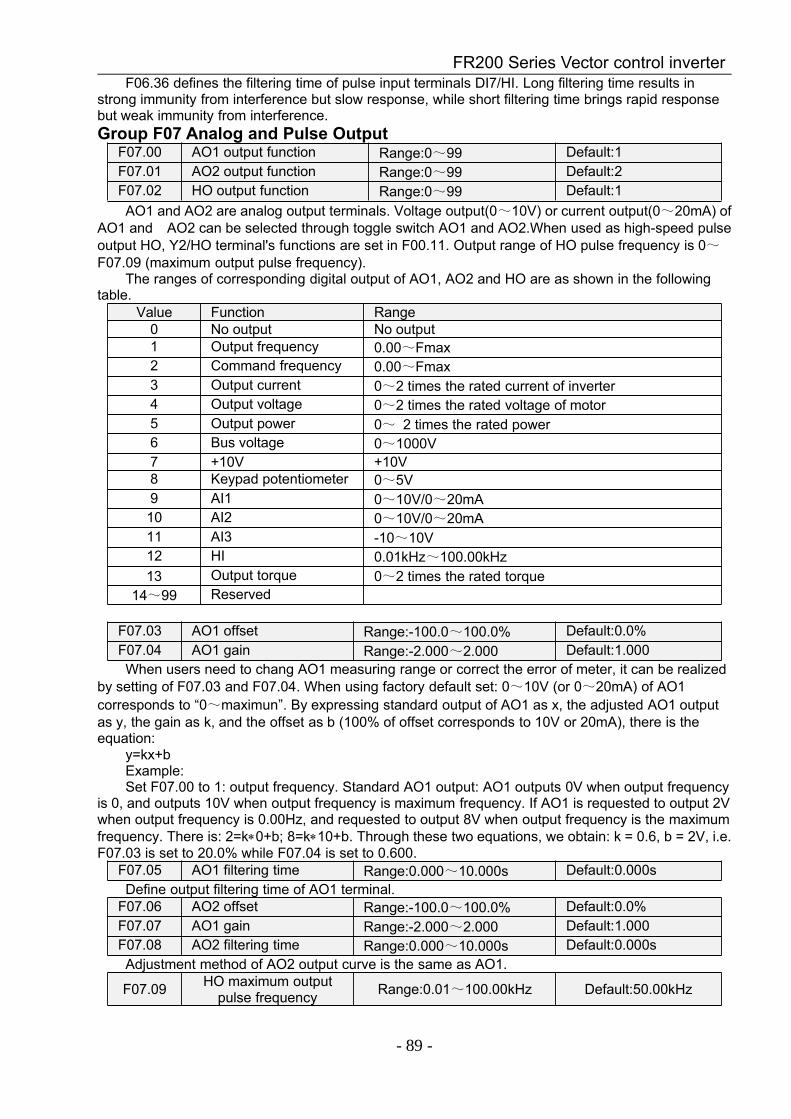
FR200 Series Vector control inverter
- 89 -
F06.36 defines the filtering time of pulse input terminals DI7/HI. Long filtering time results instrong immunity from interference but slow response, while short filtering time brings rapid responsebut weak immunity from interference.Group F07 Analog and Pulse Output
F07.00 AO1 output function Range:0~99 Default:1F07.01 AO2 output function Range:0~99 Default:2F07.02 HO output function Range:0~99 Default:1AO1 and AO2 are analog output terminals. Voltage output(0~10V) or current output(0~20mA) of
AO1 and AO2 can be selected through toggle switch AO1 and AO2.When used as high-speed pulseoutput HO, Y2/HO terminal's functions are set in F00.11. Output range of HO pulse frequency is 0~F07.09 (maximum output pulse frequency).
The ranges of corresponding digital output of AO1, AO2 and HO are as shown in the followingtable.
Value Function Range0 No output No output1 Output frequency 0.00~Fmax2 Command frequency 0.00~Fmax3 Output current 0~2 times the rated current of inverter4 Output voltage 0~2 times the rated voltage of motor5 Output power 0~ 2 times the rated power6 Bus voltage 0~1000V7 +10V +10V8 Keypad potentiometer 0~5V9 AI1 0~10V/0~20mA10 AI2 0~10V/0~20mA11 AI3 -10~10V12 HI 0.01kHz~100.00kHz13 Output torque 0~2 times the rated torque
14~99 Reserved
F07.03 AO1 offset Range:-100.0~100.0% Default:0.0%F07.04 AO1 gain Range:-2.000~2.000 Default:1.000When users need to chang AO1 measuring range or correct the error of meter, it can be realized
by setting of F07.03 and F07.04. When using factory default set: 0~10V (or 0~20mA) of AO1corresponds to “0~maximun”. By expressing standard output of AO1 as x, the adjusted AO1 outputas y, the gain as k, and the offset as b (100% of offset corresponds to 10V or 20mA), there is theequation:
y=kx+bExample:Set F07.00 to 1: output frequency. Standard AO1 output: AO1 outputs 0V when output frequency
is 0, and outputs 10V when output frequency is maximum frequency. If AO1 is requested to output 2Vwhen output frequency is 0.00Hz, and requested to output 8V when output frequency is the maximumfrequency. There is: 2=k∗0+b; 8=k∗10+b. Through these two equations, we obtain: k = 0.6, b = 2V, i.e.F07.03 is set to 20.0% while F07.04 is set to 0.600.
F07.05 AO1 filtering time Range:0.000~10.000s Default:0.000sDefine output filtering time of AO1 terminal.
F07.06 AO2 offset Range:-100.0~100.0% Default:0.0%F07.07 AO1 gain Range:-2.000~2.000 Default:1.000F07.08 AO2 filtering time Range:0.000~10.000s Default:0.000sAdjustment method of AO2 output curve is the same as AO1.
F07.09 HO maximum outputpulse frequency Range:0.01~100.00kHz Default:50.00kHz
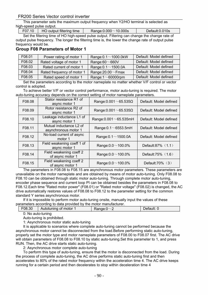
FR200 Series Vector control inverter
- 90 -
This parameter sets the maximum output frequency when Y2/HO terminal is selected ashigh-speed pulse output.
F07.10 HO output filtering time Range:0.000~10.000s Default:0.010sSet the filtering time of HO high-speed pulse output. Filtering can change the change rate of
output pulse frequency. The longer the filtering time is, the lower the change rate of output pulsefrequency would be.Group F08 Parameters of Motor 1
Set the parameters according to the motor nameplate no matter whether V/F control or vectorcontrol is adopted.
To achieve better V/F or vector control performance, motor auto-tuning is required. The motorauto-tuning accuracy depends on the correct setting of motor nameplate parameters.
F08.08 Stator resistance R1 ofasync motor 1 Range:0.001~65.535Ω Default: Model defined
F08.09 Rotor resistance R2 ofasync motor 1 Range:0.001~65.535Ω Default: Model defined
F08.10 Leakage inductance L1 ofasync motor 1 Range:0.001~65.535mH Default: Model defined
F08.11 Mutual inductance L2 ofasynchronous motor 1 Range:0.1~6553.5mH Default: Model defined
F08.12 No-load current of asyncmotor 1 Range:0.1~1500.0A Default: Model defined
F08.13 Field weakening coeff 1 ofasync motor 1 Range:0.0~100.0% Default:87%(1.1)
F08.14 Field weakening coeff 2of async motor 1 Range:0.0~100.0% Default:75%(1.6)
F08.15 Field weakening coeff 2of async motor 1 Range:0.0~100.0% Default:70%(3)
The parameters in F08.08 to F08.15 are asynchronous motor parameters. These parameters areunavailable on the motor nameplate and are obtained by means of motor auto-tuning. Only F08.08 toF08.10 can be obtained through static motor auto-tuning. Through complete motor auto-tuning,encoder phase sequence and current loop PI can be obtained besides the parameters in F08.08 toF08.12.Each time "Rated motor power" (F08.01) or "Rated motor voltage" (F08.02) is changed, the ACdrive automatically restores values of F08.08 to F08.12 to the parameter setting for the commonstandard Y series asynchronous motor.
If it is impossible to perform motor auto-tuning onsite, manually input the values of theseparameters according to data provided by the motor manufacturer.
F08.30 Autotuning of motor 1 Range:0~2 Default: 00: No auto-tuningAuto-tuning is prohibited.1: Asynchronous motor static auto-tuningIt is applicable to scenarios where complete auto-tuning cannot be performed because the
asynchronous motor cannot be disconnected from the load.Before performing static auto-tuning,properly set the motor type and motor nameplate parameters of F08.00 to F08.07 first. The AC drivewill obtain parameters of F08.08 to F08.10 by static auto-tuning.Set this parameter to 1, and pressRUN. Then, the AC drive starts static auto-tuning.
2: Asynchronous motor complete auto-tuningTo perform this type of auto-tuning, ensure that the motor is disconnected from the load. During
the process of complete auto-tuning, the AC drive performs static auto-tuning first and thenaccelerates to 80% of the rated motor frequency within the acceleration time 4. The AC drive keepsrunning for a certain period and then decelerates to stop within deceleration time 4
F08.01 Power rating of motor 1 Range:0.1~1000.0kW Default: Model definedF08.02 Rated voltage of motor 1 Range:60~660V Default: Model definedF08.03 Rated current of motor 1 Range:0.1~1500.0A Default: Model definedF08.04 Rated frequency of motor 1 Range:20.00~Fmax Default: Model definedF08.05 Rated speed of motor 1 Range:1~60000rpm Default: Model defined

FR200 Series Vector control inverter
- 91 -
Before performing complete auto-tuning, properly set the motor type, motor nameplateparameters of F08.00 to F08.07.
The AC drive will obtain motor parameters of F08.08 to F08.12 by complete auto-tuning.Set this parameter to 2, and press RUN. Then, the AC drive starts complete auto-tuning.ATTENTION:1) Please make sure the motor is in a stationary status before autotuning, or autotuning cannot be
performed normally.2) Keypad displays "TUNE", and RUN indicator is lighting during autotuning. RUN indicator
turns off upon the completion of autotuning.3) If autotuning failed, the fault code “Err17" shall be displayed.
Group F09 V/f Control Parameters of Motor 1F09.00 V/f curve setting Range:0~13 Default: 0Set the relation between output voltage and output frequency of the drive when motor 1 is under
V/f control.0: Linear V/fApplies to general constant-torque load.When drive output frequency is 0, output voltage will be 0,
while when output frequency is rated frequency of motor, the output voltage would be rated voltage ofmotor.
1: Broken line V/f (determined by F09.03~F09.10)Applies to spin drier, centrifuge, industrial washing machine and to other special loads. When
drive output frequency is 0, output voltage will be 0, while when output frequency is rated frequency ofmotor, the output voltage would be rated voltage of motor. What is different is this pattern can set 4inflection points by F09.03~F09.10.
2: 1.2nd power3: 1.4th power4: 1.6th power5: 1.8th power6: 2.0th powerParameter values 2~6 apply to torque-dropped loads such as fans and water pumps. See Fig.
6-16.
Fig. 6-167: V/F complete separationIn this mode, the output frequency and output voltage of the AC drive are independent. The
output frequency is determined by the frequency source, and the output voltage is determined by"Voltage source for V/F separation" (F09.15).It is applicable to induction heating, inverse power supplyand torque motor control.
8: V/F half separationIn this mode, V and F are proportional and the proportional relationship can be set in F09.15.
The relationship between V and F are also related to the rated motor voltage and rated motorfrequency in Group F08.Assume that the voltage source input is X (0 to 100%), the relationshipbetween V and F is:
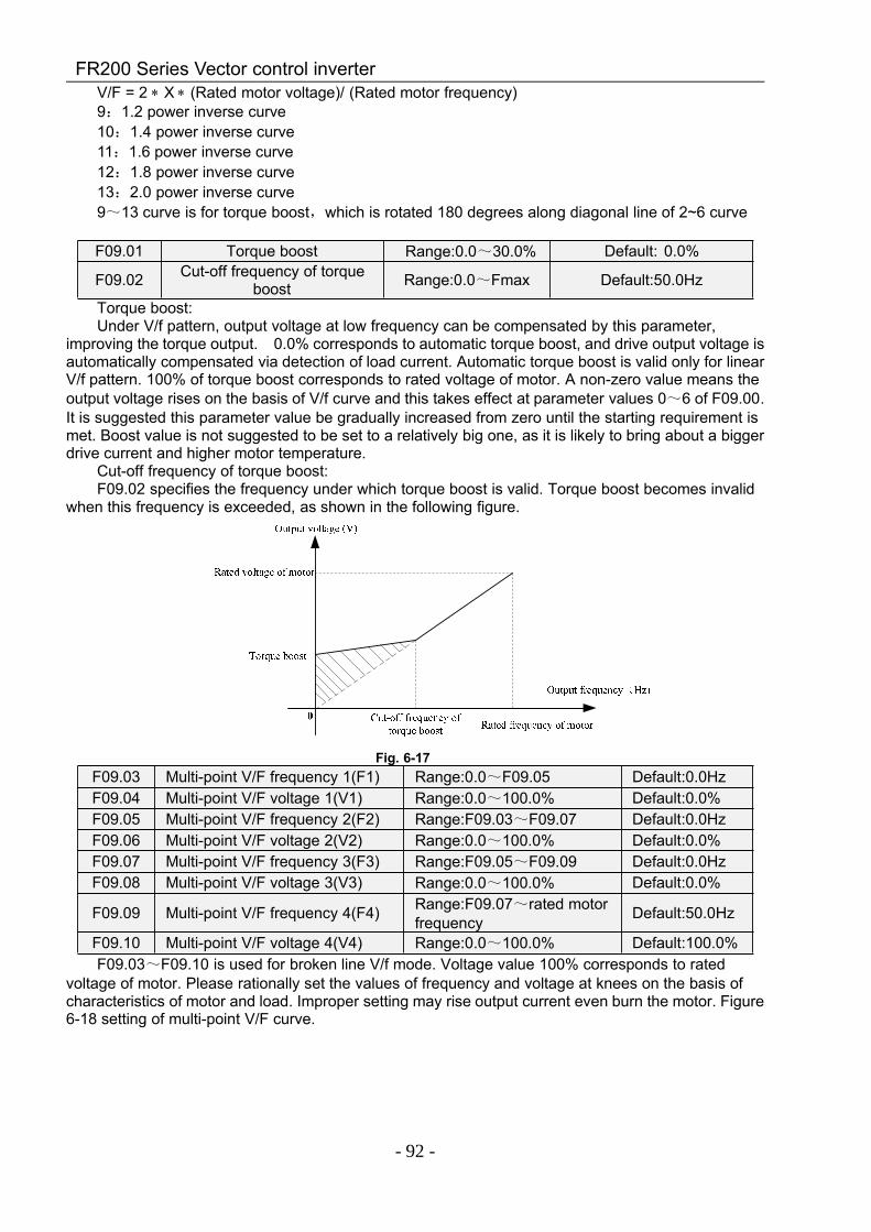
FR200 Series Vector control inverter
- 92 -
V/F = 2 ∗ X ∗ (Rated motor voltage)/ (Rated motor frequency)9:1.2 power inverse curve10:1.4 power inverse curve11:1.6 power inverse curve12:1.8 power inverse curve13:2.0 power inverse curve9~13 curve is for torque boost,which is rotated 180 degrees along diagonal line of 2~6 curve
F09.01 Torque boost Range:0.0~30.0% Default: 0.0%
F09.02 Cut-off frequency of torqueboost Range:0.0~Fmax Default:50.0Hz
Torque boost:Under V/f pattern, output voltage at low frequency can be compensated by this parameter,
improving the torque output. 0.0% corresponds to automatic torque boost, and drive output voltage isautomatically compensated via detection of load current. Automatic torque boost is valid only for linearV/f pattern. 100% of torque boost corresponds to rated voltage of motor. A non-zero value means theoutput voltage rises on the basis of V/f curve and this takes effect at parameter values 0~6 of F09.00.It is suggested this parameter value be gradually increased from zero until the starting requirement ismet. Boost value is not suggested to be set to a relatively big one, as it is likely to bring about a biggerdrive current and higher motor temperature.
Cut-off frequency of torque boost:F09.02 specifies the frequency under which torque boost is valid. Torque boost becomes invalid
when this frequency is exceeded, as shown in the following figure.
Fig. 6-17F09.03 Multi-point V/F frequency 1(F1) Range:0.0~F09.05 Default:0.0HzF09.04 Multi-point V/F voltage 1(V1) Range:0.0~100.0% Default:0.0%F09.05 Multi-point V/F frequency 2(F2) Range:F09.03~F09.07 Default:0.0HzF09.06 Multi-point V/F voltage 2(V2) Range:0.0~100.0% Default:0.0%F09.07 Multi-point V/F frequency 3(F3) Range:F09.05~F09.09 Default:0.0HzF09.08 Multi-point V/F voltage 3(V3) Range:0.0~100.0% Default:0.0%
F09.09 Multi-point V/F frequency 4(F4) Range:F09.07~rated motorfrequency Default:50.0Hz
F09.10 Multi-point V/F voltage 4(V4) Range:0.0~100.0% Default:100.0%F09.03~F09.10 is used for broken line V/f mode. Voltage value 100% corresponds to rated
voltage of motor. Please rationally set the values of frequency and voltage at knees on the basis ofcharacteristics of motor and load. Improper setting may rise output current even burn the motor. Figure6-18 setting of multi-point V/F curve.
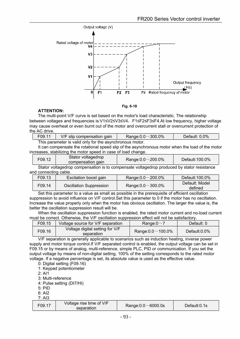
FR200 Series Vector control inverter
- 93 -
Fig. 6-18ATTENTION:The multi-point V/F curve is set based on the motor's load characteristic. The relationship
between voltages and frequencies is:V1≤V2≤V3≤V4,F1≤F2≤F3≤F4.At low frequency, higher voltagemay cause overheat or even burnt out of the motor and overcurrent stall or overcurrent protection ofthe AC drive.
F09.11 V/F slip compensation gain Range:0.0~300.0% Default: 0.0%This parameter is valid only for the asynchronous motor.It can compensate the rotational speed slip of the asynchronous motor when the load of the motor
increases, stabilizing the motor speed in case of load change.
F09.12 Stator voltagedropcompensation gain Range:0.0~200.0% Default:100.0%
Stator voltagedrop compensation is to compensate voltagedrop produced by stator resistanceand connecting cable.
F09.13 Excitation boost gain Range:0.0~200.0% Default:100.0%
F09.14 Oscillation Suppression Range:0.0~300.0% Default: Modeldefined
Set this parameter to a value as small as possible in the prerequisite of efficient oscillationsuppression to avoid influence on V/F control.Set this parameter to 0 if the motor has no oscillation.Increase the value properly only when the motor has obvious oscillation. The larger the value is, thebetter the oscillation suppression result will be.
When the oscillation suppression function is enabled, the rated motor current and no-load currentmust be correct. Otherwise, the V/F oscillation suppression effect will not be satisfactory.
F09.15 Voltage source for V/F separation Range:0~7 Default: 0
F09.16 Voltage digital setting for V/Fseparation Range:0.0~100.0% Default:0.0%
V/F separation is generally applicable to scenarios such as induction heating, inverse powersupply and motor torque control.If V/F separated control is enabled, the output voltage can be set inF09.15 or by means of analog, multi-reference, simple PLC, PID or communication. If you set theoutput voltage by means of non-digital setting, 100% of the setting corresponds to the rated motorvoltage. If a negative percentage is set, its absolute value is used as the effective value.
0: Digital setting (F09.16)1: Keypad potentiometer2: AI13: Multi-reference4: Pulse setting (DI7/HI)5: PID6: AI27: AI3
F09.17 Voltage rise time of V/Fseparation Range:0.0~6000.0s Default:0.1s
FR200 Series Vector control inverter
- 94 -
This parameter value is the time rising from 0V to motor rated voltage or dropping from ratedvoltage to 0V.Group F10 Vector Control Parameters of Motor 1
F10.00 Speed/torque control Range:0~1 Default: 0Sensor-less vector control 2 and close-loop vector control support torque control. Under these two
control patterns, speed control and torque control can be programmed by this parameter.Added to this,the switchover between speed control and torque control can also be realized by digital input terminal"speed/torque control switch". The relation of the switchover via terminal and parameter is shown inthe following table:
F10.00 Speed/torque controlswitch terminal Control mode
0 OFF Speed control0 ON Torque control1 OFF Torque control1 ON Speed control
Under speed control, output torque of motor will match load automatically. In order to avoidovercurrent fault caused by excessive output torque, it is necessary to set appropriate torque limitvalue and keep output torque of motor within this limit. Please refer to the specification of F10.10 fortorque limited information.
Under torque control, torque can be set by different sources, by F10.16. Under torque control,motor speed is determined by the difference between set torque and load torque. When the set torqueis bigger than load torque, motor will be accelerated continuously. When the set torque is smaller thanload torque, motor will be decelerated continuously. When the set torque is matching load torque well,the speed of motor will be maintained. Therefore, it is necessary to set limit value of forward or reversespeed during torque control so as to prevent over-run caused by continuous acceleration of motor.Please set the speed limits in F10.18~F10.19 under torque control.
ATTENTION:Jog mode will run in the manner of speed control, and torque control is disabled.
F10.01 ASR low-speed proportionalgain Kp1 Range:0.0~100.0 Default:30.0
F10.02 ASR low-speed integrationtime Ti1 Range:0.00~10.00s Default:0.50s
F10.03 ASR switching frequency 1 Range:0.0~F10.06 Default:5.0HzF10.04 ASR high-speed
proportional gain Kp2 Range:0.0~100.0 Default:15.0
F10.05 ASR high-speed integrationtime Ti2 Range:0.00~10.00s Default:1.00s
F10.06 ASR switching frequency 2 Range:F10.03~Fup Default:10.0HzSpeed loop PI parameters vary with running frequencies of the AC drive.If the running frequency is less than or equal to "Switchover frequency 1" (F10.03), the speed loop
PI parameters are F10.00 and F10.01.If the running frequency is equal to or greater than "Switchover frequency 2" (F10.06), the speed
loop PI parameters are F10.04 and F10.05.If the running frequency is between F10.03 and F10.03, the speed loop PI parameters are
obtained from the linear switchover between the two groups of PI parameters.The speed dynamic response characteristics in vector control can be adjusted by setting
theproportional gain and integral time of the speed regulator.To achieve a faster system response,increase the proportional gain and reduce the integral time. Be aware that this may lead to systemoscillation.
The recommended adjustment method is as follows:If the factory setting cannot meet the requirements, make proper adjustment. Increase the
proportional gain first to ensure that the system does not oscillate, and then reduce the integral time toensure that the system has quick response and small overshoot.
ATTENTION:Improper PI parameter setting may cause too large speed overshoot, and overvoltage fault may
even occur when the overshoot drops.
FR200 Series Vector control inverter
- 95 -
F10.07 ASR input filtering time Range:0.0~500.0ms Default:0.3msF10.08 ASR output filtering time Range:0.0~500.0ms Default:0.3msSets the input/output filtering time of ASR.No need to modify its default setting if not have special
requirement.F10.09 Vector control slip gain Range:50~200% Default:100%For SFVC, it is used to adjust speed stability accuracy of the motor. When the motor with load
runs at a very low speed, increase the value of this parameter; when the motor with load runs at a verylarge speed, decrease the value of this parameter.
For CLVC, it is used to adjust the output current of the AC drive with same load.
F10.10 Digital setting of torque upperlimit in speed control mode Range:50.0~200.0% Default:100%
In the speed control mode, the maximum output torque of the AC drive is restricted by F10.10.
F10.11 Excitation adjustmentproportional gain Kp1 Range:0.00~10.00 Default:0.50
F10.12 Excitation adjustment integralgain Ti1 Range:0.0~3000.0ms Default:10.0ms
F10.13 Torque adjustmentproportional gain Kp2 Range:0.00~10.00 Default:0.50
F10.14 Torque adjustment integralgain Ti2 Range:0.0~3000.0ms Default:10.0ms
These are current loop PI parameters for vector control. These parameters are automaticallyobtained through "Asynchronous motor complete auto-tuning" or "Synchronous motor no-loadauto-tuning", and need not be modified.
F10.16 Torque setting source undertorque control Range:0~6 Default:0
F10.17 Digital setting of torque Range:-200~200% Default:150.0%F10.16 is used to set the torque setting source. There are a total of 6 torque setting sources.The torque setting is a relative value. 100.0% corresponds to the AC drives rated torque. The
setting range is -200.0% to 200.0%, indicating the AC drive's maximum torque is twice of the ACdrive's rated torque.
If the torque setting is positive, the AC drive rotates in forward direction. If the torque setting isnegative, the AC drive rotates in reverse direction.
0: Digital setting (F10.17)The target torque directly uses the value set in F10.17.1: Keypad potentiometer2: AI13: AI24: AI3The target torque is decided by analog input.5: Pulse setting (DI7/HI)The target torque is set by DI7/HI (high-speed pulse). The pulse setting signal specification is
9–30 V (voltage range) and 0–100 kHz (frequency range). The pulse can only be input via DI7.6: Communication settingThe target torque is set by means of communication.
F10.18 Forward speed limited valueunder torque control Range:0.0~Fmax Default:50.0Hz
F10.19 Reverse speed limited valueunder torque control Range:0.0~Fmax Default:50.0Hz
When F00.26=0,Two parameters are used to set the maximum frequency in forward or reverserotation in torque control mode.
In torque control, if the load torque is smaller than the motor output torque, the motor's rotationalspeed will rise continuously. To avoid runaway of the mechanical system, the motor maximum rotatingspeed must be limited in torque control.
You can implement continuous change of the maximum frequency in torque control dynamicallyby controlling the frequency upper limit.
FR200 Series Vector control inverter
- 96 -
F10.20 Set torque accel time Range:0.0~6000.0s Default:0.0sF10.21 Set torque decel time Range:0.0~6000.0s Default:0.0sIn torque control, the difference between the motor output torque and the load torque determines
the speed change rate of the motor and load. The motor rotational speed may change quickly and thiswill result in noise or too large mechanical stress. The setting of acceleration/deceleration time intorque control makes the motor rotational speed change softly.
However, in applications requiring rapid torque response, set theacceleration/deceleratio time intorque control to 0.00s.
For example, two AC drives are connected to drive the same load. To balance the load allocation,set one AC drive as master in speed control and the other as slave in torque control. The slavereceives the master's output torque as the torque command and must follow the master rapidly. In thiscase, the acceleration/deceleration time of the slave in torque control is set to 0.0s.
F10.22 Static friction torquecompensation Range:0.0~100.0% Default:5.0%
F10.23 Static friction frequency range Range:0.0~20.0Hz Default:1.0HzThis parameter takes effect only in torque control. To compensate the static friction of system at
the start, additional torque might be needed. When the motor runs, static friction torque compensationis disabled. 100% corresponds to rated torque of motor.
F10.24 Sliding friction torquecompensation Range:0.0~100.0% Default:1.0%
This parameter takes effect only in torque control. To compensate the sliding friction duringrunning, additional torque might be needed. 100% corresponds to rated torque of motor.
F10.25 Rotary inertia compensationcoeff Range:50.0~200.0% Default:100.0%
This parameter takes effect only in torque control. This parameter value is to compensatemechanical rotary inertia during acceleration/deceleration.
F10.26 Max Frequency sourceunder torque control
0: Set by F10.18 & F10.19
0 ×
1:Keypad potentiometer2:AI13:AI24:AI35: Pulse setting ( DI7/HI )
This parameter takes effect only in torque control. F10.26 is used to set the Max frequency sourceunder torque control.
Group F11 Protection ParametersF11.00 Current limit control Range:0~2 Default:2F11.01 Current limit Range:100.0~200.0% Default:150.0%
F11.02 Frequency decreasing time (limitcurrent in constant speed operation) Range:0.0~6000.0s Default:5.0s
F11.03 Current limit mode 2 proportio gain Range:0.1~100.0% Default:3.0%F11.04 Current limit mode 2 integral time Range:0.000~1.000s Default:0.010sF11.00=0:Current limit disabledF11.00=1:Current limit mode 1During acceleration and deceleration, if output current exceeds current limit (F11.01), inverter
stops acceleration/deceleration and remains at present running frequency, and willaccelerate/decelerate as per previous acceleration/deceleration time after output current decreased.
During steady state, after output current exceeds the current limit (F11.01), inverter deceleratesas per the decreasing time (F11.02) of constant speed current frequency, and the minimumdeceleration could reach lower limit frequency (F01.10). After output current decreases, inverterwillaccelerate to setting frequency as per setting acceleration time, see Figure 6-19.
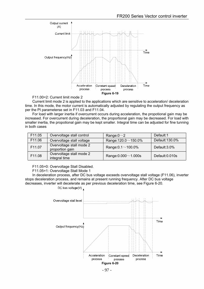
FR200 Series Vector control inverter
- 97 -
Figure 6-19F11.00=2: Current limit mode 2Current limit mode 2 is applied to the applications which are sensitive to acceleration/ deceleration
time. In this mode, the motor current is automatically adjusted by regulating the output frequency asper the PI parameterse set in F11.03 and F11.04.
For load with larger inertia if overcurrent occurs during acceleration, the propotional gain may beincreased. For overcurrent during deceleration, the proportional gain may be decreased. For load withsmaller inertia, the propotional gain may be kept smaller. Integral time can be adjusted for fine tunningin both cases
F11.05 Overvoltage stall control Range:0~2 Default:1F11.06 Overvoltage stall voltage Range:120.0~150.0% Default:130.0%
F11.07 Overvoltage stall mode 2proportion gain Range:0.1~100.0% Default:3.0%
F11.08 Overvoltage stall mode 2integral time Range:0.000~1.000s Default:0.010s
F11.05=0: Overvoltage Stall Disabled.F11.05=1: Overvoltage Stall Mode 1In deceleration process, after DC bus voltage exceeds overvoltage stall voltage (F11.06), inverter
stops deceleration process, and remains at present running frequency. After DC bus voltagedecreases, inverter will decelerate as per previous deceleration time, see Figure 6-20.
Figure 6-20
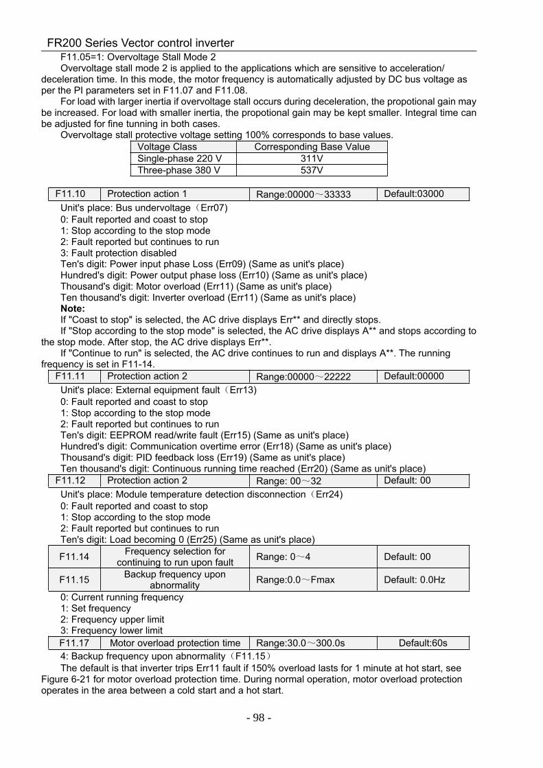
FR200 Series Vector control inverter
- 98 -
F11.05=1: Overvoltage Stall Mode 2Overvoltage stall mode 2 is applied to the applications which are sensitive to acceleration/
deceleration time. In this mode, the motor frequency is automatically adjusted by DC bus voltage asper the PI parameters set in F11.07 and F11.08.
For load with larger inertia if overvoltage stall occurs during deceleration, the propotional gain maybe increased. For load with smaller inertia, the propotional gain may be kept smaller. Integral time canbe adjusted for fine tunning in both cases.
Overvoltage stall protective voltage setting 100% corresponds to base values.Voltage Class Corresponding Base ValueSingle-phase 220 V 311VThree-phase 380 V 537V
F11.10 Protection action 1 Range:00000~33333 Default:03000Unit's place: Bus undervoltage(Err07)0: Fault reported and coast to stop1: Stop according to the stop mode2: Fault reported but continues to run3: Fault protection disabledTen's digit: Power input phase Loss (Err09) (Same as unit's place)Hundred's digit: Power output phase loss (Err10) (Same as unit's place)Thousand's digit: Motor overload (Err11) (Same as unit's place)Ten thousand's digit: Inverter overload (Err11) (Same as unit's place)Note:If "Coast to stop" is selected, the AC drive displays Err** and directly stops.If "Stop according to the stop mode" is selected, the AC drive displays A** and stops according to
the stop mode. After stop, the AC drive displays Err**.If "Continue to run" is selected, the AC drive continues to run and displays A**. The running
frequency is set in F11-14.F11.11 Protection action 2 Range:00000~22222 Default:00000Unit's place: External equipment fault(Err13)0: Fault reported and coast to stop1: Stop according to the stop mode2: Fault reported but continues to runTen's digit: EEPROM read/write fault (Err15) (Same as unit's place)Hundred's digit: Communication overtime error (Err18) (Same as unit's place)Thousand's digit: PID feedback loss (Err19) (Same as unit's place)Ten thousand's digit: Continuous running time reached (Err20) (Same as unit's place)
F11.12 Protection action 2 Range: 00~32 Default: 00Unit's place: Module temperature detection disconnection(Err24)0: Fault reported and coast to stop1: Stop according to the stop mode2: Fault reported but continues to runTen's digit: Load becoming 0 (Err25) (Same as unit's place)
F11.14 Frequency selection forcontinuing to run upon fault Range: 0~4 Default: 00
F11.15 Backup frequency uponabnormality Range:0.0~Fmax Default: 0.0Hz
0: Current running frequency1: Set frequency2: Frequency upper limit3: Frequency lower limitF11.17 Motor overload protection time Range:30.0~300.0s Default:60s4: Backup frequency upon abnormality(F11.15)The default is that inverter trips Err11 fault if 150% overload lasts for 1 minute at hot start, see
Figure 6-21 for motor overload protection time. During normal operation, motor overload protectionoperates in the area between a cold start and a hot start.
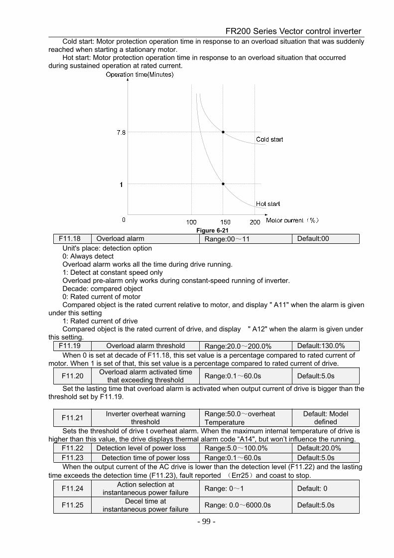
FR200 Series Vector control inverter
- 99 -
Cold start: Motor protection operation time in response to an overload situation that was suddenlyreached when starting a stationary motor.
Hot start: Motor protection operation time in response to an overload situation that occurredduring sustained operation at rated current.
Figure 6-21F11.18 Overload alarm Range:00~11 Default:00Unit's place: detection option0: Always detectOverload alarm works all the time during drive running.1: Detect at constant speed onlyOverload pre-alarm only works during constant-speed running of inverter.Decade: compared object0: Rated current of motorCompared object is the rated current relative to motor, and display " A11" when the alarm is given
under this setting1: Rated current of driveCompared object is the rated current of drive, and display " A12" when the alarm is given under
this setting.F11.19 Overload alarm threshold Range:20.0~200.0% Default:130.0%When 0 is set at decade of F11.18, this set value is a percentage compared to rated current of
motor. When 1 is set of that, this set value is a percentage compared to rated current of drive.
F11.20 Overload alarm activated timethat exceeding threshold Range:0.1~60.0s Default:5.0s
Set the lasting time that overload alarm is activated when output current of drive is bigger than thethreshold set by F11.19.
F11.21 Inverter overheat warningthreshold
Range:50.0~overheatTemperature
Default: Modeldefined
Sets the threshold of drive t overheat alarm. When the maximum internal temperature of drive ishigher than this value, the drive displays thermal alarm code “A14", but won’t influence the running.
F11.22 Detection level of power loss Range:5.0~100.0% Default:20.0%F11.23 Detection time of power loss Range:0.1~60.0s Default:5.0sWhen the output current of the AC drive is lower than the detection level (F11.22) and the lasting
time exceeds the detection time (F11.23), fault reported (Err25)and coast to stop.
F11.24 Action selection atinstantaneous power failure Range: 0~1 Default: 0
F11.25 Decel time atinstantaneous power failure Range: 0.0~6000.0s Default:5.0s
FR200 Series Vector control inverter
- 100 -
0: Disabled1: EnabledUnder momentary voltage drop or momentary power loss, the drive will accordingly drop output
frequency, and compensate the voltage drop via the energy feedback from load, so as to maintainconsecutive running, no trip. This function applies to fans and centrifugal pumps and such.
F11.26 Rapid current limit Range: 0~1 Default: 00: Disabled1: EnabledThe rapid current limit function can reduce the AC drive's overcurrent faults at maximum,
guaranteeing uninterrupted running of the AC drive.However, long-time rapid current limit may causethe AC drive to overheat, which is not allowed. In this case, the AC drive will report Err26, indicatingthe AC drive is overloaded and needs to stop
F11.27 Times of automatic reset Range:0~20 Default: 0It is used to set the times of fault auto resets if this function is used. After the value is exceeded,
the AC drive will remain in the fault state.F11.28 Interval of automatic reset Range:0.1~100.0s Default:1.0sIt is used to set the waiting time from the alarm of the AC drive to fault auto reset.
F11.29 DO action during fault autoreset Range:0~1 Default: 0
0: Not act1: ActIt is used to decide whether the DO acts during the fault auto reset if the fault auto reset function is
selected.Group F12 Multi-Reference and Simple PLC Function
F12.00 Reference 0 Range:-100.0~100.0% Default:0.0%F12.01 Reference 1 Range:-100.0~100.0% Default:0.0%F12.02 Reference 2 Range:-100.0~100.0% Default:0.0%F12.03 Reference 3 Range:-100.0~100.0% Default:0.0%F12.04 Reference 4 Range:-100.0~100.0% Default:0.0%F12.05 Reference 5 Range:-100.0~100.0% Default:0.0%F12.06 Reference 6 Range:-100.0~100.0% Default:0.0%F12.07 Reference 7 Range:-100.0~100.0% Default:0.0%F12.08 Reference 8 Range:-100.0~100.0% Default:0.0%F12.09 Reference 9 Range:-100.0~100.0% Default:0.0%F12.10 Reference 10 Range:-100.0~100.0% Default:0.0%F12.11 Reference 11 Range:-100.0~100.0% Default:0.0%F12.12 Reference 12 Range:-100.0~100.0% Default:0.0%F12.13 Reference 13 Range:-100.0~100.0% Default:0.0%F12.14 Reference 14 Range:-100.0~100.0% Default:0.0%F12.15 Reference 15 Range:-100.0~100.0% Default:0.0%At most 16 steps of multi-feference can be set by different status combinations of
" multi-feference terminals 1~4" of digital input.Multi-reference can be the setting source of frequency, V/F separated voltage and process PID.
The multi-reference is relative value and ranges from -100.0% to 100.0%.As frequency source, it is a percentage relative to the maximum frequency. As V/F separated
voltage source, it is a percentage relative to the rated motor voltage. As process PID setting source, itdoes not require conversion.
Multi-reference can be switched over based on different states of DI terminals. For details, see thedescriptions of group F4.
F12.16 Reference 0 source Range:0~6 Default: 00: Digital setting(F12.00)1: keypad potentiometer2:AI13: Process PID output
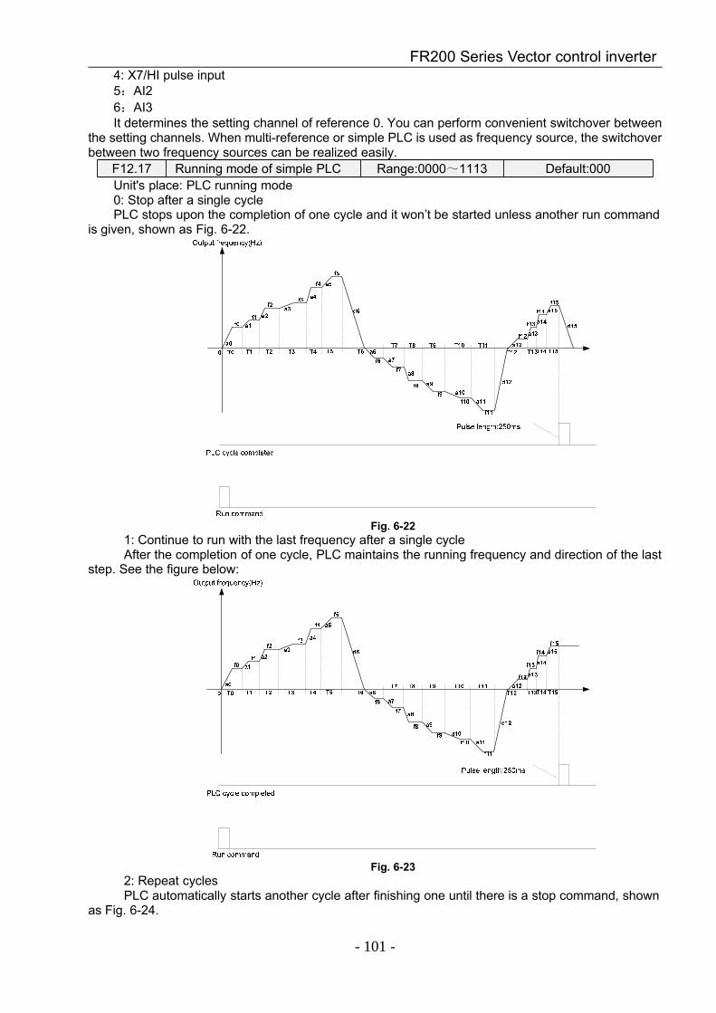
FR200 Series Vector control inverter
- 101 -
4: X7/HI pulse input5:AI26:AI3It determines the setting channel of reference 0. You can perform convenient switchover between
the setting channels. When multi-reference or simple PLC is used as frequency source, the switchoverbetween two frequency sources can be realized easily.
F12.17 Running mode of simple PLC Range:0000~1113 Default:000Unit's place: PLC running mode0: Stop after a single cyclePLC stops upon the completion of one cycle and it won’t be started unless another run command
is given, shown as Fig. 6-22.
Fig. 6-221: Continue to run with the last frequency after a single cycleAfter the completion of one cycle, PLC maintains the running frequency and direction of the last
step. See the figure below:
Fig. 6-232: Repeat cyclesPLC automatically starts another cycle after finishing one until there is a stop command, shown
as Fig. 6-24.
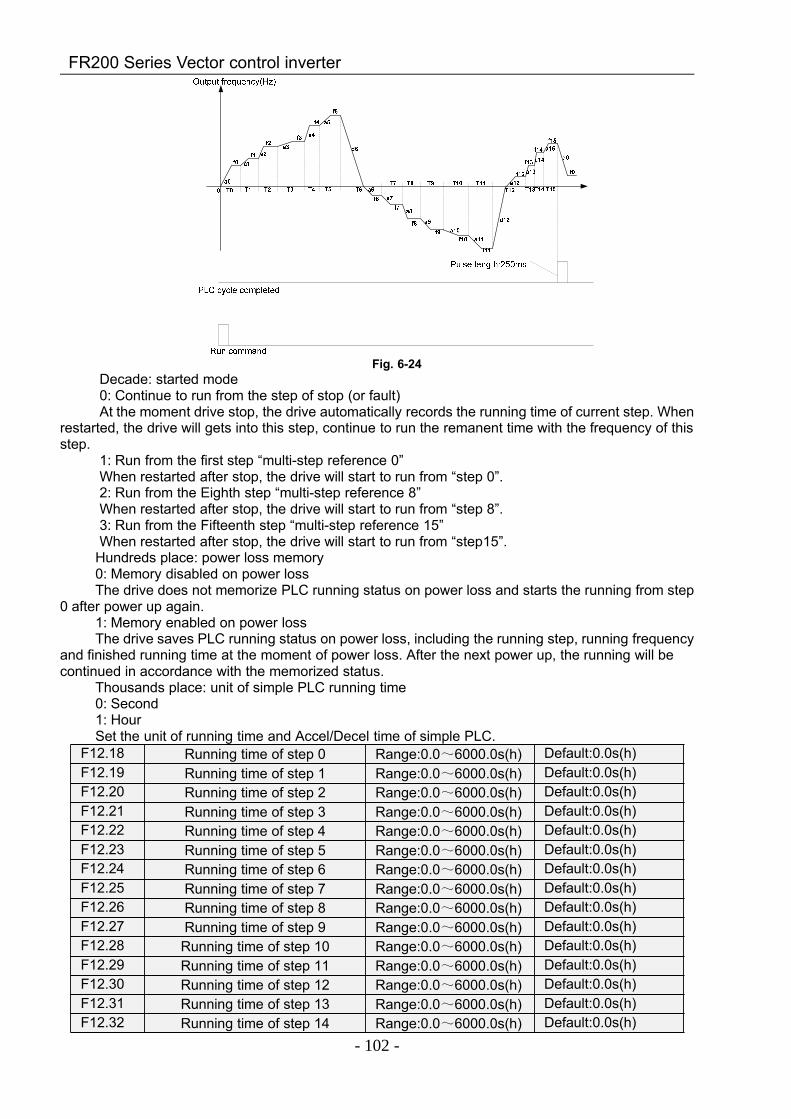
FR200 Series Vector control inverter
- 102 -
Fig. 6-24Decade: started mode0: Continue to run from the step of stop (or fault)At the moment drive stop, the drive automatically records the running time of current step. When
restarted, the drive will gets into this step, continue to run the remanent time with the frequency of thisstep.
1: Run from the first step “multi-step reference 0”When restarted after stop, the drive will start to run from “step 0”.2: Run from the Eighth step “multi-step reference 8”When restarted after stop, the drive will start to run from “step 8”.3: Run from the Fifteenth step “multi-step reference 15”When restarted after stop, the drive will start to run from “step15”.
Hundreds place: power loss memory0: Memory disabled on power lossThe drive does not memorize PLC running status on power loss and starts the running from step
0 after power up again.1: Memory enabled on power lossThe drive saves PLC running status on power loss, including the running step, running frequency
and finished running time at the moment of power loss. After the next power up, the running will becontinued in accordance with the memorized status.
Thousands place: unit of simple PLC running time0: Second1: HourSet the unit of running time and Accel/Decel time of simple PLC.
F12.18 Running time of step 0 Range:0.0~6000.0s(h) Default:0.0s(h)F12.19 Running time of step 1 Range:0.0~6000.0s(h) Default:0.0s(h)F12.20 Running time of step 2 Range:0.0~6000.0s(h) Default:0.0s(h)F12.21 Running time of step 3 Range:0.0~6000.0s(h) Default:0.0s(h)F12.22 Running time of step 4 Range:0.0~6000.0s(h) Default:0.0s(h)F12.23 Running time of step 5 Range:0.0~6000.0s(h) Default:0.0s(h)F12.24 Running time of step 6 Range:0.0~6000.0s(h) Default:0.0s(h)F12.25 Running time of step 7 Range:0.0~6000.0s(h) Default:0.0s(h)F12.26 Running time of step 8 Range:0.0~6000.0s(h) Default:0.0s(h)F12.27 Running time of step 9 Range:0.0~6000.0s(h) Default:0.0s(h)F12.28 Running time of step 10 Range:0.0~6000.0s(h) Default:0.0s(h)F12.29 Running time of step 11 Range:0.0~6000.0s(h) Default:0.0s(h)F12.30 Running time of step 12 Range:0.0~6000.0s(h) Default:0.0s(h)F12.31 Running time of step 13 Range:0.0~6000.0s(h) Default:0.0s(h)F12.32 Running time of step 14 Range:0.0~6000.0s(h) Default:0.0s(h)
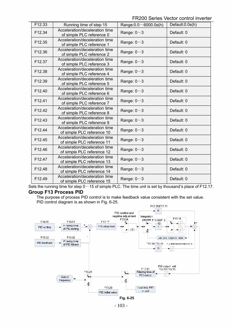
FR200 Series Vector control inverter
- 103 -
F12.33 Running time of step 15 Range:0.0~6000.0s(h) Default:0.0s(h)
F12.34 Acceleration/deceleration timeof simple PLC reference 0 Range: 0~3 Default: 0
F12.35 Acceleration/deceleration timeof simple PLC reference 1 Range: 0~3 Default: 0
F12.36 Acceleration/deceleration timeof simple PLC reference 2 Range: 0~3 Default: 0
F12.37 Acceleration/deceleration timeof simple PLC reference 3 Range: 0~3 Default: 0
F12.38 Acceleration/deceleration timeof simple PLC reference 4 Range: 0~3 Default: 0
F12.39 Acceleration/deceleration timeof simple PLC reference 5 Range: 0~3 Default: 0
F12.40 Acceleration/deceleration timeof simple PLC reference 6 Range: 0~3 Default: 0
F12.41 Acceleration/deceleration timeof simple PLC reference 7 Range: 0~3 Default: 0
F12.42 Acceleration/deceleration timeof simple PLC reference 8 Range: 0~3 Default: 0
F12.43 Acceleration/deceleration timeof simple PLC reference 9 Range: 0~3 Default: 0
F12.44 Acceleration/deceleration timeof simple PLC reference 10 Range: 0~3 Default: 0
F12.45 Acceleration/deceleration timeof simple PLC reference 11 Range: 0~3 Default: 0
F12.46 Acceleration/deceleration timeof simple PLC reference 12 Range: 0~3 Default: 0
F12.47 Acceleration/deceleration timeof simple PLC reference 13 Range: 0~3 Default: 0
F12.48 Acceleration/deceleration timeof simple PLC reference 14 Range: 0~3 Default: 0
F12.49 Acceleration/deceleration timeof simple PLC reference 15 Range: 0~3 Default: 0
Sets the running time for step 0~15 of simple PLC. The time unit is set by thousand’s place of F12.17.Group F13 Process PID
The purpose of process PID control is to make feedback value consistent with the set value.PID control diagram is as shown in Fig. 6-25.
Fig. 6-25
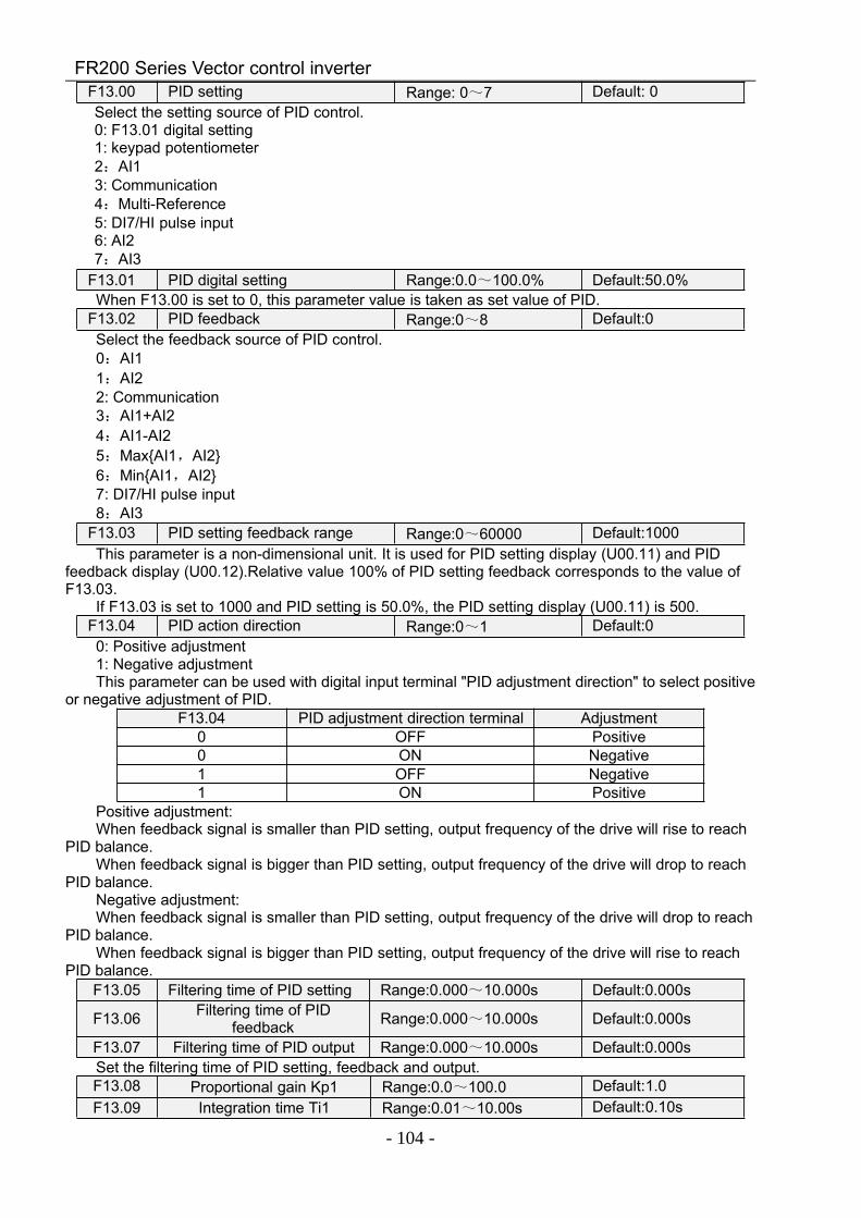
FR200 Series Vector control inverter
- 104 -
F13.00 PID setting Range: 0~7 Default: 0Select the setting source of PID control.0: F13.01 digital setting1: keypad potentiometer2:AI13: Communication4:Multi-Reference5: DI7/HI pulse input6: AI27:AI3
F13.01 PID digital setting Range:0.0~100.0% Default:50.0%When F13.00 is set to 0, this parameter value is taken as set value of PID.
F13.02 PID feedback Range:0~8 Default:0Select the feedback source of PID control.0:AI11:AI22: Communication3:AI1+AI24:AI1-AI25:MaxAI1,AI26:MinAI1,AI27: DI7/HI pulse input8:AI3
F13.03 PID setting feedback range Range:0~60000 Default:1000This parameter is a non-dimensional unit. It is used for PID setting display (U00.11) and PID
feedback display (U00.12).Relative value 100% of PID setting feedback corresponds to the value ofF13.03.
If F13.03 is set to 1000 and PID setting is 50.0%, the PID setting display (U00.11) is 500.F13.04 PID action direction Range:0~1 Default:00: Positive adjustment1: Negative adjustmentThis parameter can be used with digital input terminal "PID adjustment direction" to select positive
or negative adjustment of PID.F13.04 PID adjustment direction terminal Adjustment
0 OFF Positive0 ON Negative1 OFF Negative1 ON Positive
Positive adjustment:When feedback signal is smaller than PID setting, output frequency of the drive will rise to reach
PID balance.When feedback signal is bigger than PID setting, output frequency of the drive will drop to reach
PID balance.Negative adjustment:When feedback signal is smaller than PID setting, output frequency of the drive will drop to reach
PID balance.When feedback signal is bigger than PID setting, output frequency of the drive will rise to reach
PID balance.F13.05 Filtering time of PID setting Range:0.000~10.000s Default:0.000s
F13.06 Filtering time of PIDfeedback Range:0.000~10.000s Default:0.000s
F13.07 Filtering time of PID output Range:0.000~10.000s Default:0.000sSet the filtering time of PID setting, feedback and output.F13.08 Proportional gain Kp1 Range:0.0~100.0 Default:1.0F13.09 Integration time Ti1 Range:0.01~10.00s Default:0.10s
FR200 Series Vector control inverter
- 105 -
F13.10 Differential time Td1 Range:0.000~10.000s Default:0.000sProportional gain Kp1:It decides the regulating intensity of the PID regulator. The higher the Kp1 is, the larger the
regulating intensity is. The value 100.0 indicates when the deviation between PID feedback and PIDsetting is 100.0%; the adjustment amplitude of the PID regulator on the output frequency reference isthe maximum frequency.
Integral time Ti1:It decides the integral regulating intensity. The shorter the integral time is, the larger the regulating
intensity is. When the deviation between PID feedback and PID setting is 100.0%, the integralregulator performs continuous adjustment for the time set in FA-06. Then the adjustment amplitudereaches the maximum frequency.
Differential time Td1:It decides the regulating intensity of the PID regulator on the deviation change. The longer the
differential time is, the larger the regulating intensity is. Differential time is the time within which thefeedback value change reaches 100.0%, and then the adjustment amplitude reaches the maximumfrequency.
F13.11 Proportional gain Kp2 Range:0.0~100.0 Default:1.0F13.12 Integration time Ti2 Range:0.01~10.00s Default:0.10sF13.13 Differential time Td2 Range:0.000~10.000s Default:0.000sIn some applications, PID parameters switchover is required when one group of PID parameters
cannot satisfy the requirement of the whole running process.These parameters are used forswitchover between two groups of PID parameters. Regulator parameters F13.11 to F13.13 are set inthe same way as F13.08 to F13.10.
F13.14 PID parameter switch Range:0~2 Default: 0
F13.15 PID parameter switchoverdeviation 1 Range:0.0~100.0% Default:20.0%
F13.16 PID parameter switchoverdeviation 2 Range:0.0~100.0% Default:80.0%
Process PID is provided with two groups of proportional, integral and differential parameters,which is set by this parameter.
0: No switch, determined by parameters Kp1, Ti1 and Td1Always determined by Kp1, Ti1 and Td1 set at F13.08 to F13.10.1: Auto switched on the basis of input offsetWhen the offset between setting and feedback is less than the set value of F13.15, PID
adjustment is determined by Kp1, Ti1 and Td1. When the offset between setting and feedback isbigger than the set value of F13.15, PID adjustment is determined by Kp2, Ti2 and Td2 set at F13.11to F13.13.
2: Switched by terminalWhen digital input terminal "PID parameters switch" is OFF, it is determined by Kp1, Ti1 and Td1.
When "PID parameters switch" is ON, it is determined by Kp2, Ti2 and Td2F13.17 PID offset limit Range:0.0~100.0% Default:1.0%If the offset between PID feedback and setting is more than this set value, PID regulator will
implement regulation. If the offset between PID feedback and setting is less than this set value, PIDwill stop the regulation and the PID controller output will be kept unchanged. This function can improvethe stability of PID performance.
F13.18 PID integral property Range:00~11 Default:00Unit's digit (Whether to stop integral operation when the output reaches the limit)0: Continue integral operation1: Stop integral operationIf "Stop integral operation" is selected, the PID integral operation stops, which may help to reduce
the PID, overshoot.Ten's digit (Integral separated)0: Invalid1: ValidIf it is set to valid, the PID integral operation stops when the DI allocated with function 25 "PID
integral pause" is ON In this case, only proportional and differential operations take effect.
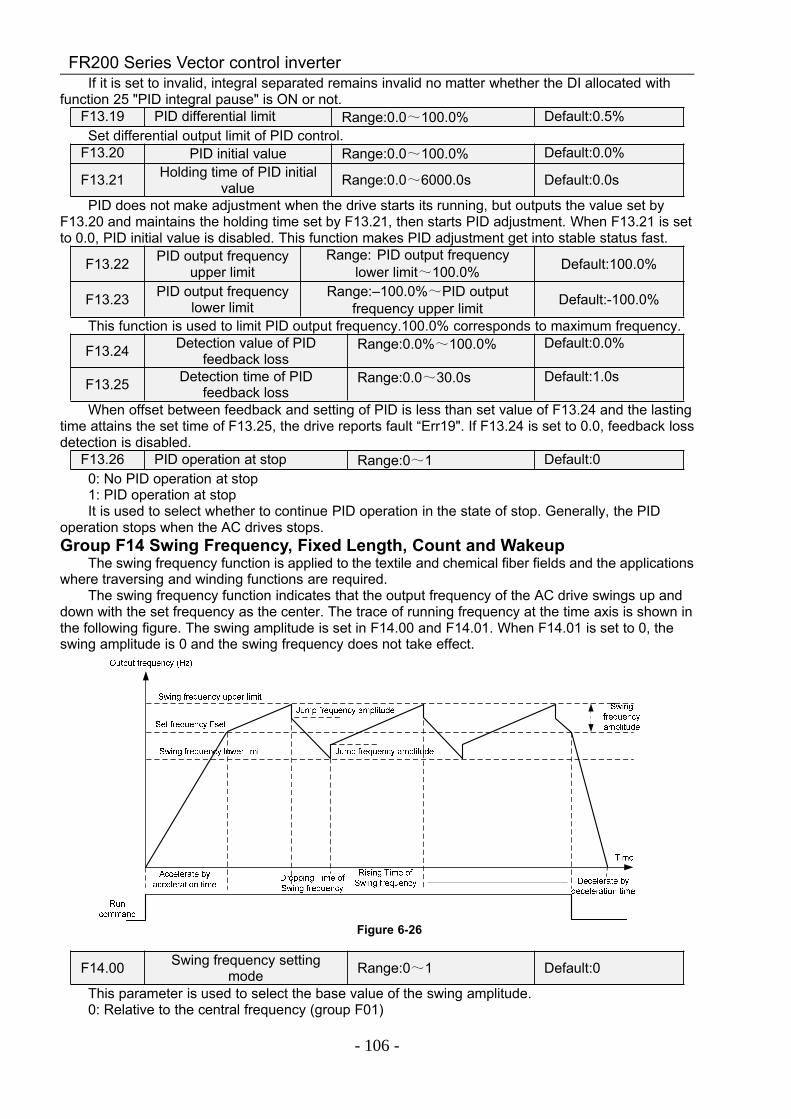
FR200 Series Vector control inverter
- 106 -
If it is set to invalid, integral separated remains invalid no matter whether the DI allocated withfunction 25 "PID integral pause" is ON or not.
F13.19 PID differential limit Range:0.0~100.0% Default:0.5%Set differential output limit of PID control.
F13.20 PID initial value Range:0.0~100.0% Default:0.0%
F13.21 Holding time of PID initialvalue Range:0.0~6000.0s Default:0.0s
PID does not make adjustment when the drive starts its running, but outputs the value set byF13.20 and maintains the holding time set by F13.21, then starts PID adjustment. When F13.21 is setto 0.0, PID initial value is disabled. This function makes PID adjustment get into stable status fast.
F13.22 PID output frequencyupper limit
Range: PID output frequencylower limit~100.0% Default:100.0%
F13.23 PID output frequencylower limit
Range:–100.0%~PID outputfrequency upper limit Default:-100.0%
This function is used to limit PID output frequency.100.0% corresponds to maximum frequency.
F13.24 Detection value of PIDfeedback loss
Range:0.0%~100.0% Default:0.0%
F13.25 Detection time of PIDfeedback loss
Range:0.0~30.0s Default:1.0s
When offset between feedback and setting of PID is less than set value of F13.24 and the lastingtime attains the set time of F13.25, the drive reports fault “Err19". If F13.24 is set to 0.0, feedback lossdetection is disabled.
F13.26 PID operation at stop Range:0~1 Default:00: No PID operation at stop1: PID operation at stopIt is used to select whether to continue PID operation in the state of stop. Generally, the PID
operation stops when the AC drives stops.Group F14 Swing Frequency, Fixed Length, Count and Wakeup
The swing frequency function is applied to the textile and chemical fiber fields and the applicationswhere traversing and winding functions are required.
The swing frequency function indicates that the output frequency of the AC drive swings up anddown with the set frequency as the center. The trace of running frequency at the time axis is shown inthe following figure. The swing amplitude is set in F14.00 and F14.01. When F14.01 is set to 0, theswing amplitude is 0 and the swing frequency does not take effect.
Figure 6-26
F14.00 Swing frequency settingmode Range:0~1 Default:0
This parameter is used to select the base value of the swing amplitude.0: Relative to the central frequency (group F01)
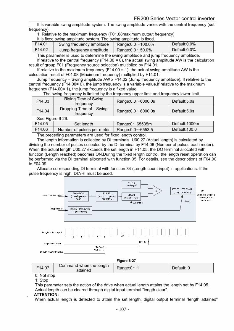
FR200 Series Vector control inverter
- 107 -
It is variable swing amplitude system. The swing amplitude varies with the central frequency (setfrequency).
1: Relative to the maximum frequency (F01.08maximum output frequency)It is fixed swing amplitude system. The swing amplitude is fixed.
F14.01 Swing frequency amplitude Range:0.0~100.0% Default:0.0%F14.02 Jump frequency amplitude Range:0.0~50.0% Default:0.0%This parameter is used to determine the swing amplitude and jump frequency amplitude.If relative to the central frequency (F14.00 = 0), the actual swing amplitude AW is the calculation
result of group F01 (Frequency source selection) multiplied by F14.01.If relative to the maximum frequency (F14.00 = 1), the actual swing amplitude AW is the
calculation result of F01.08 (Maximum frequency) multiplied by F14.01.Jump frequency = Swing amplitude AW x F14.02 (Jump frequency amplitude). If relative to the
central frequency (F14.00= 0), the jump frequency is a variable value.If relative to the maximumfrequency (F14.00= 1), the jump frequency is a fixed value.
The swing frequency is limited by the frequency upper limit and frequency lower limit.
F14.03 Rising Time of Swingfrequency Range:0.0~6000.0s Default:5.0s
F14.04 Dropping Time of Swingfrequency Range:0.0~6000.0s Default:5.0s
See Figure 6-26.F14.05 Set length Range:0~65535m Default:1000mF14.06 Number of pulses per meter Range:0.0~6553.5 Default:100.0The preceding parameters are used for fixed length control.The length information is collected by DI terminals. U00.27 (Actual length) is calculated by
dividing the number of pulses collected by the DI terminal by F14.06 (Number of pulses each meter).When the actual length U00.27 exceeds the set length in F14.05, the DO terminal allocated withfunction (Length reached) becomes ON.During the fixed length control, the length reset operation canbe performed via the DI terminal allocated with function 35. For details, see the descriptions of F04.00to F04.09.
Allocate corresponding DI terminal with function 34 (Length count input) in applications. If thepulse frequency is high, DI7/HI must be used.
Figure 6-27
F14.07 Command when the lengthattained Range:0~1 Default: 0
0: Not stop1: StopThis parameter sets the action of the drive when actual length attains the length set by F14.05.Actual length can be cleared through digital input terminal "length clear".
ATTENTION: When actual length is detected to attain the set length, digital output terminal "length attained"
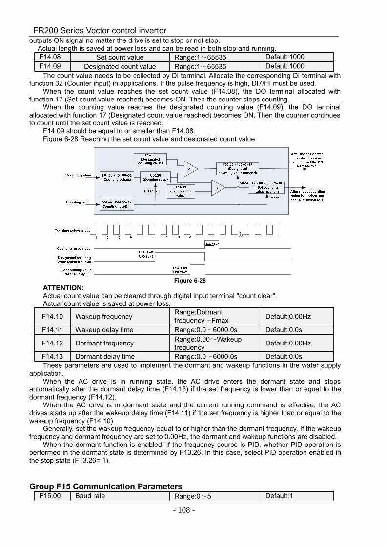
FR200 Series Vector control inverter
- 108 -
outputs ON signal no matter the drive is set to stop or not stop. Actual length is saved at power loss and can be read in both stop and running.
F14.08 Set count value Range:1~65535 Default:1000F14.09 Designated count value Range:1~65535 Default:1000The count value needs to be collected by DI terminal. Allocate the corresponding DI terminal with
function 32 (Counter input) in applications. If the pulse frequency is high, DI7/HI must be used.When the count value reaches the set count value (F14.08), the DO terminal allocated with
function 17 (Set count value reached) becomes ON. Then the counter stops counting.When the counting value reaches the designated counting value (F14.09), the DO terminal
allocated with function 17 (Designated count value reached) becomes ON. Then the counter continuesto count until the set count value is reached.
F14.09 should be equal to or smaller than F14.08.Figure 6-28 Reaching the set count value and designated count value
Figure 6-28ATTENTION:Actual count value can be cleared through digital input terminal "count clear".Actual count value is saved at power loss.
F14.10 Wakeup frequency Range:Dormantfrequency~Fmax Default:0.00Hz
F14.11 Wakeup delay time Range:0.0~6000.0s Default:0.0s
F14.12 Dormant frequency Range:0.00~Wakeupfrequency Default:0.00Hz
F14.13 Dormant delay time Range:0.0~6000.0s Default:0.0sThese parameters are used to implement the dormant and wakeup functions in the water supply
application.When the AC drive is in running state, the AC drive enters the dormant state and stops
automatically after the dormant delay time (F14.13) if the set frequency is lower than or equal to thedormant frequency (F14.12).
When the AC drive is in dormant state and the current running command is effective, the ACdrives starts up after the wakeup delay time (F14.11) if the set frequency is higher than or equal to thewakeup frequency (F14.10).
Generally, set the wakeup frequency equal to or higher than the dormant frequency. If the wakeupfrequency and dormant frequency are set to 0.00Hz, the dormant and wakeup functions are disabled.
When the dormant function is enabled, if the frequency source is PID, whether PID operation isperformed in the dormant state is determined by F13.26. In this case, select PID operation enabled inthe stop state (F13.26= 1).
Group F15 Communication ParametersF15.00 Baud rate Range:0~5 Default:1
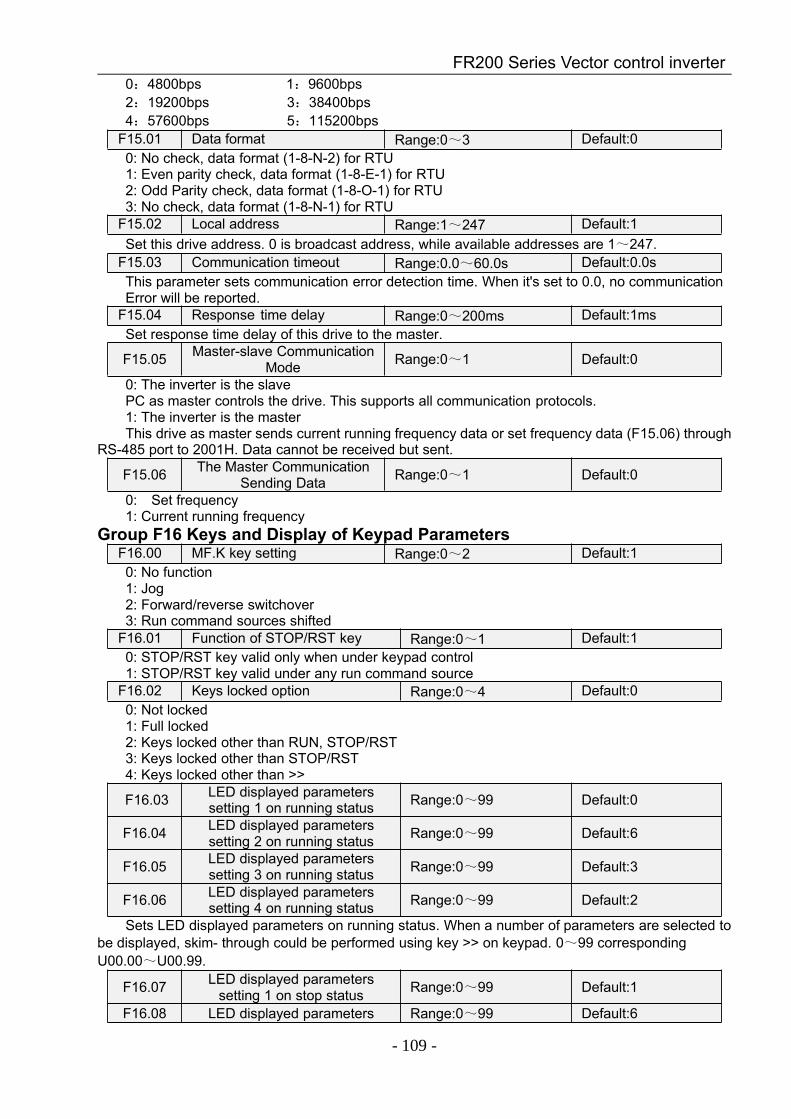
FR200 Series Vector control inverter
- 109 -
0:4800bps 1:9600bps2:19200bps 3:38400bps4:57600bps 5:115200bps
F15.01 Data format Range:0~3 Default:00: No check, data format (1-8-N-2) for RTU1: Even parity check, data format (1-8-E-1) for RTU2: Odd Parity check, data format (1-8-O-1) for RTU3: No check, data format (1-8-N-1) for RTU
F15.02 Local address Range:1~247 Default:1Set this drive address. 0 is broadcast address, while available addresses are 1~247.
F15.03 Communication timeout Range:0.0~60.0s Default:0.0sThis parameter sets communication error detection time. When it's set to 0.0, no communicationError will be reported.
F15.04 Response time delay Range:0~200ms Default:1msSet response time delay of this drive to the master.
F15.05 Master-slave CommunicationMode Range:0~1 Default:0
0: The inverter is the slavePC as master controls the drive. This supports all communication protocols.1: The inverter is the masterThis drive as master sends current running frequency data or set frequency data (F15.06) through
RS-485 port to 2001H. Data cannot be received but sent.
F15.06 The Master CommunicationSending Data Range:0~1 Default:0
0: Set frequency1: Current running frequency
Group F16 Keys and Display of Keypad ParametersF16.00 MF.K key setting Range:0~2 Default:10: No function1: Jog2: Forward/reverse switchover3: Run command sources shifted
F16.01 Function of STOP/RST key Range:0~1 Default:10: STOP/RST key valid only when under keypad control1: STOP/RST key valid under any run command source
F16.02 Keys locked option Range:0~4 Default:00: Not locked1: Full locked2: Keys locked other than RUN, STOP/RST3: Keys locked other than STOP/RST4: Keys locked other than >>
F16.03 LED displayed parameterssetting 1 on running status Range:0~99 Default:0
F16.04 LED displayed parameterssetting 2 on running status Range:0~99 Default:6
F16.05 LED displayed parameterssetting 3 on running status Range:0~99 Default:3
F16.06 LED displayed parameterssetting 4 on running status Range:0~99 Default:2
Sets LED displayed parameters on running status. When a number of parameters are selected tobe displayed, skim- through could be performed using key >> on keypad. 0~99 correspondingU00.00~U00.99.
F16.07 LED displayed parameterssetting 1 on stop status Range:0~99 Default:1
F16.08 LED displayed parameters Range:0~99 Default:6
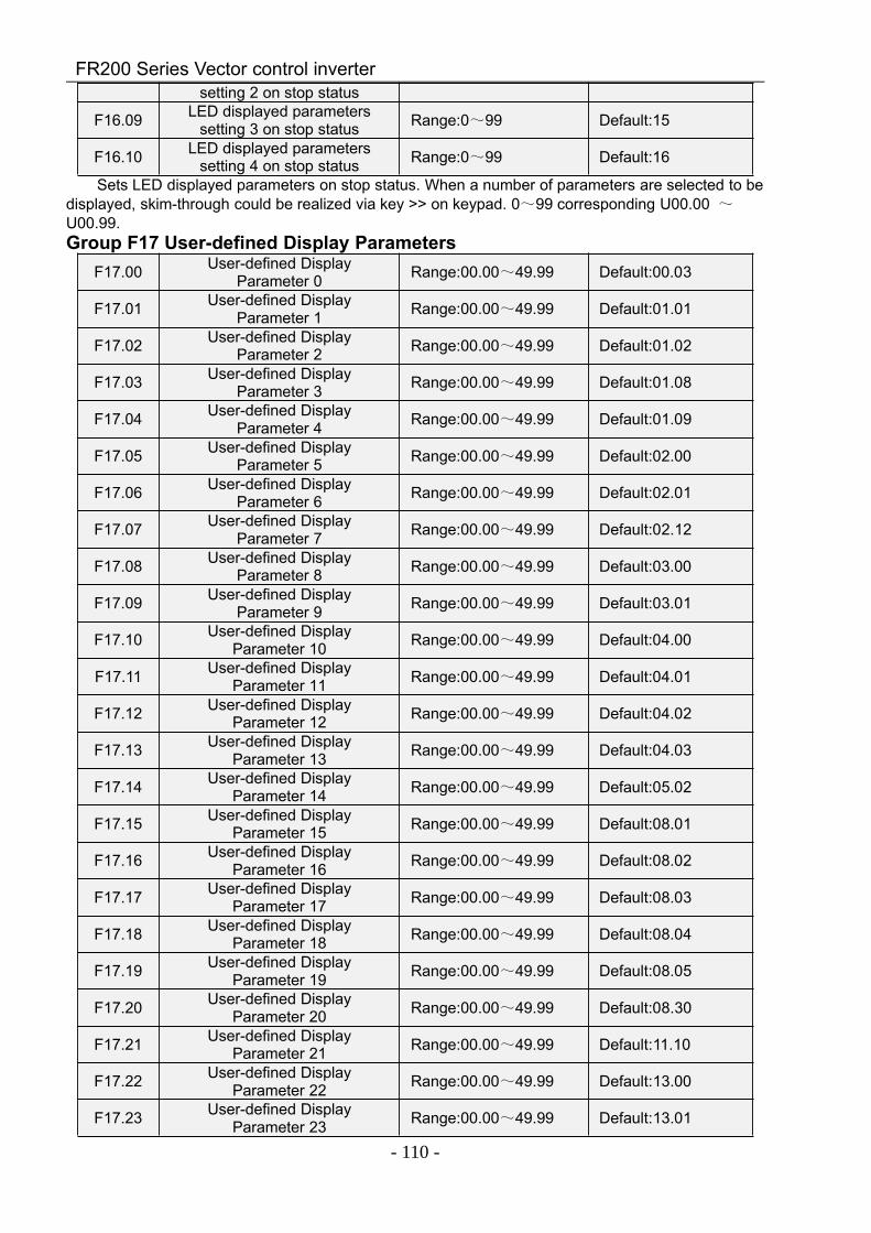
FR200 Series Vector control inverter
- 110 -
setting 2 on stop status
F16.09 LED displayed parameterssetting 3 on stop status Range:0~99 Default:15
F16.10 LED displayed parameterssetting 4 on stop status Range:0~99 Default:16
Sets LED displayed parameters on stop status. When a number of parameters are selected to bedisplayed, skim-through could be realized via key >> on keypad. 0~99 corresponding U00.00 ~U00.99.Group F17 User-defined Display Parameters
F17.00 User-defined DisplayParameter 0 Range:00.00~49.99 Default:00.03
F17.01 User-defined DisplayParameter 1 Range:00.00~49.99 Default:01.01
F17.02 User-defined DisplayParameter 2 Range:00.00~49.99 Default:01.02
F17.03 User-defined DisplayParameter 3 Range:00.00~49.99 Default:01.08
F17.04 User-defined DisplayParameter 4 Range:00.00~49.99 Default:01.09
F17.05 User-defined DisplayParameter 5 Range:00.00~49.99 Default:02.00
F17.06 User-defined DisplayParameter 6 Range:00.00~49.99 Default:02.01
F17.07 User-defined DisplayParameter 7 Range:00.00~49.99 Default:02.12
F17.08 User-defined DisplayParameter 8 Range:00.00~49.99 Default:03.00
F17.09 User-defined DisplayParameter 9 Range:00.00~49.99 Default:03.01
F17.10 User-defined DisplayParameter 10 Range:00.00~49.99 Default:04.00
F17.11 User-defined DisplayParameter 11 Range:00.00~49.99 Default:04.01
F17.12 User-defined DisplayParameter 12 Range:00.00~49.99 Default:04.02
F17.13 User-defined DisplayParameter 13 Range:00.00~49.99 Default:04.03
F17.14 User-defined DisplayParameter 14 Range:00.00~49.99 Default:05.02
F17.15 User-defined DisplayParameter 15 Range:00.00~49.99 Default:08.01
F17.16 User-defined DisplayParameter 16 Range:00.00~49.99 Default:08.02
F17.17 User-defined DisplayParameter 17 Range:00.00~49.99 Default:08.03
F17.18 User-defined DisplayParameter 18 Range:00.00~49.99 Default:08.04
F17.19 User-defined DisplayParameter 19 Range:00.00~49.99 Default:08.05
F17.20 User-defined DisplayParameter 20 Range:00.00~49.99 Default:08.30
F17.21 User-defined DisplayParameter 21 Range:00.00~49.99 Default:11.10
F17.22 User-defined DisplayParameter 22 Range:00.00~49.99 Default:13.00
F17.23 User-defined DisplayParameter 23 Range:00.00~49.99 Default:13.01
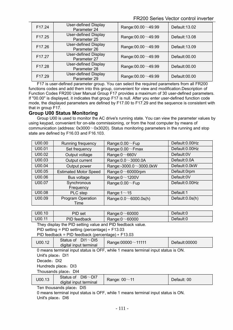
FR200 Series Vector control inverter
- 111 -
F17.24 User-defined DisplayParameter 24 Range:00.00~49.99 Default:13.02
F17.25 User-defined DisplayParameter 25 Range:00.00~49.99 Default:13.08
F17.26 User-defined DisplayParameter 26 Range:00.00~49.99 Default:13.09
F17.27 User-defined DisplayParameter 27 Range:00.00~49.99 Default:00.00
F17.28 User-defined DisplayParameter 28 Range:00.00~49.99 Default:00.00
F17.29 User-defined DisplayParameter 29 Range:00.00~49.99 Default:00.00
F17 is user-defined parameter group. You can select the required parameters from all FR200functions codes and add them into this group, convenient for view and modification.Description ofFunction Codes FR200 User Manual Group F17 provides a maximum of 30 user-defined parameters.If "00.00" is displayed, it indicates that group F17 is null. After you enter user-defined function codemode, the displayed parameters are defined by F17.00 to F17.29 and the sequence is consistent withthat in group F17.Group U00 Status Monitoring
Group U00 is used to monitor the AC drive's running state. You can view the parameter values byusing keypad, convenient for on-site commissioning, or from the host computer by means ofcommunication (address: 0x3000~0x3020). Status monitoring parameters in the running and stopstate are defined by F16.03 and F16.103.
U00.00 Running frequency Range:0.00~Fup Default:0.00HzU00.01 Set frequency Range:0.00~Fmax Default:0.00HzU00.02 Output voltage Range:0~660V Default:0VU00.03 Output current Range:0.0~3000.0A Default:0.0AU00.04 Output power Range:-3000.0~3000.0kW Default:0.0kWU00.05 Estimated Motor Speed Range:0~60000rpm Default:0rpmU00.06 Bus voltage Range:0~1200V Default:0VU00.07 Synchronous
FrequencyRange:0.00~Fup Default:0.00Hz
U00.08 PLC step Range:1~15 Default:1U00.09 Program Operation
TimeRange:0.0~6000.0s(h) Default:0.0s(h)
U00.10 PID set Range:0~60000 Default:0U00.11 PID feedback Range:0~60000 Default:0They display the PID setting value and PID feedback value.PID setting = PID setting (percentage) ∗ F13.03PID feedback = PID feedback (percentage) ∗ F13.03
U00.12 Status of DI1~DI5digital input terminal Range:00000~11111 Default:00000
0 means terminal input status is OFF, while 1 means terminal input status is ON.Unit's place:DI1Decade:DI2Hundreds place:DI3Thousands place:DI4
U00.13 Status of DI6~DI7digital input terminal Range: 00~11 Default: 00
Ten thousands place:DI50 means terminal input status is OFF, while 1 means terminal input status is ON.Unit's place:DI6
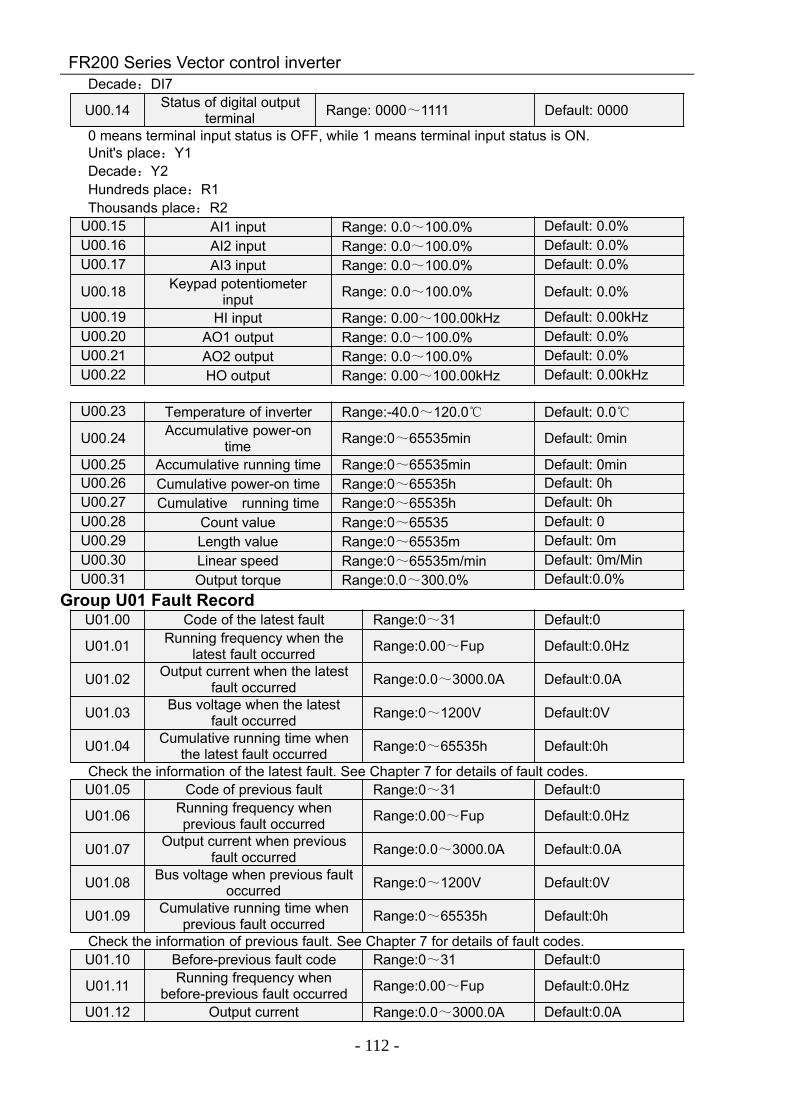
FR200 Series Vector control inverter
- 112 -
Decade:DI7
U00.14 Status of digital outputterminal Range: 0000~1111 Default: 0000
0 means terminal input status is OFF, while 1 means terminal input status is ON.Unit's place:Y1Decade:Y2Hundreds place:R1Thousands place:R2
U00.15 AI1 input Range: 0.0~100.0% Default: 0.0%U00.16 AI2 input Range: 0.0~100.0% Default: 0.0%U00.17 AI3 input Range: 0.0~100.0% Default: 0.0%
U00.18 Keypad potentiometerinput Range: 0.0~100.0% Default: 0.0%
U00.19 HI input Range: 0.00~100.00kHz Default: 0.00kHzU00.20 AO1 output Range: 0.0~100.0% Default: 0.0%U00.21 AO2 output Range: 0.0~100.0% Default: 0.0%U00.22 HO output Range: 0.00~100.00kHz Default: 0.00kHz
U00.23 Temperature of inverter Range:-40.0~120.0 Default: 0.0
U00.24 Accumulative power-ontime Range:0~65535min Default: 0min
U00.25 Accumulative running time Range:0~65535min Default: 0minU00.26 Cumulative power-on time Range:0~65535h Default: 0hU00.27 Cumulative running time Range:0~65535h Default: 0hU00.28 Count value Range:0~65535 Default: 0U00.29 Length value Range:0~65535m Default: 0mU00.30 Linear speed Range:0~65535m/min Default: 0m/MinU00.31 Output torque Range:0.0~300.0% Default:0.0%
Group U01 Fault RecordU01.00 Code of the latest fault Range:0~31 Default:0
U01.01 Running frequency when thelatest fault occurred Range:0.00~Fup Default:0.0Hz
U01.02 Output current when the latestfault occurred Range:0.0~3000.0A Default:0.0A
U01.03 Bus voltage when the latestfault occurred Range:0~1200V Default:0V
U01.04 Cumulative running time whenthe latest fault occurred Range:0~65535h Default:0h
Check the information of the latest fault. See Chapter 7 for details of fault codes.U01.05 Code of previous fault Range:0~31 Default:0
U01.06 Running frequency whenprevious fault occurred Range:0.00~Fup Default:0.0Hz
U01.07 Output current when previousfault occurred Range:0.0~3000.0A Default:0.0A
U01.08 Bus voltage when previous faultoccurred Range:0~1200V Default:0V
U01.09 Cumulative running time whenprevious fault occurred Range:0~65535h Default:0h
Check the information of previous fault. See Chapter 7 for details of fault codes.U01.10 Before-previous fault code Range:0~31 Default:0
U01.11 Running frequency whenbefore-previous fault occurred Range:0.00~Fup Default:0.0Hz
U01.12 Output current Range:0.0~3000.0A Default:0.0A
FR200 Series Vector control inverter
- 113 -
whenbefore-previous faultoccurred
U01.13 Bus voltage whenbefore-previous fault occurred Range:0~1200V Default:0V
U01.14 Cumulative running time whenbefore-previous fault occurred Range:0~65535h Default:0h
Check the information of before-previous fault (the fault sequence: before-previous fault, previousfault, latest fault). See Chapter 7 for details of fault code
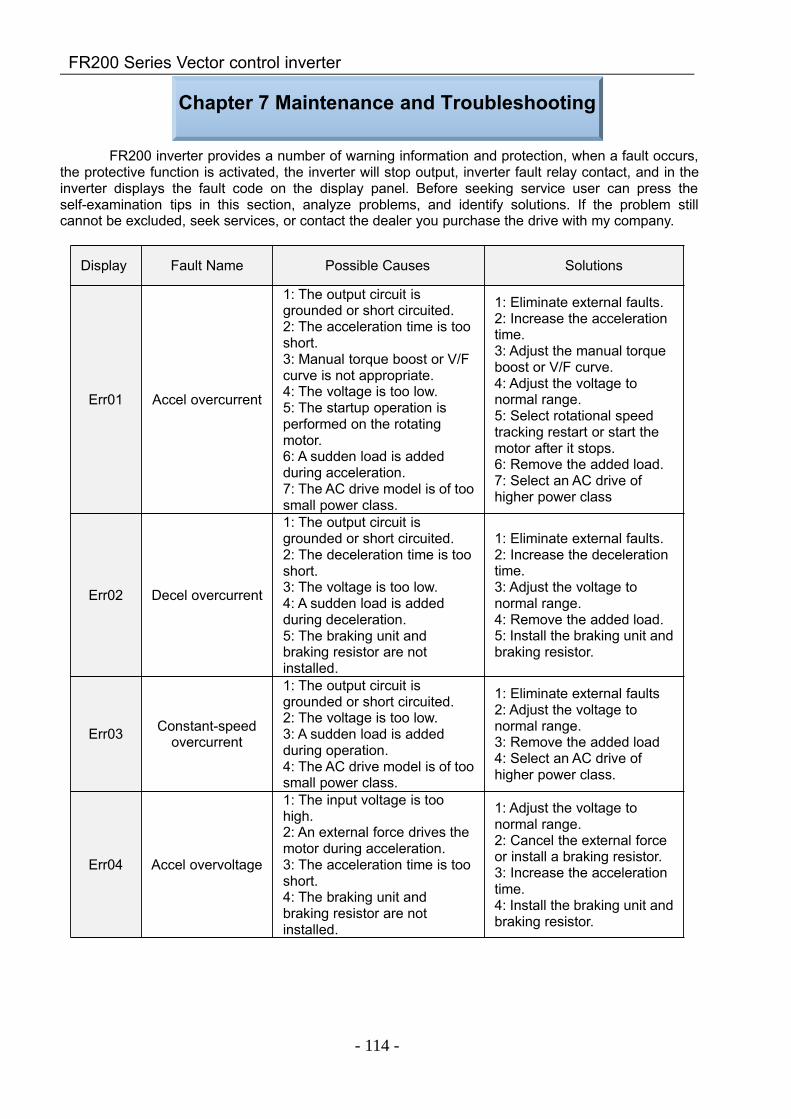
FR200 Series Vector control inverter
- 114 -
Chapter 7 Maintenance and Troubleshooting
FR200 inverter provides a number of warning information and protection, when a fault occurs,the protective function is activated, the inverter will stop output, inverter fault relay contact, and in theinverter displays the fault code on the display panel. Before seeking service user can press theself-examination tips in this section, analyze problems, and identify solutions. If the problem stillcannot be excluded, seek services, or contact the dealer you purchase the drive with my company.
Display Fault Name Possible Causes Solutions
Err01 Accel overcurrent
1: The output circuit isgrounded or short circuited.2: The acceleration time is tooshort.3: Manual torque boost or V/Fcurve is not appropriate.4: The voltage is too low.5: The startup operation isperformed on the rotatingmotor.6: A sudden load is addedduring acceleration.7: The AC drive model is of toosmall power class.
1: Eliminate external faults.2: Increase the accelerationtime.3: Adjust the manual torqueboost or V/F curve.4: Adjust the voltage tonormal range.5: Select rotational speedtracking restart or start themotor after it stops.6: Remove the added load.7: Select an AC drive ofhigher power class
Err02 Decel overcurrent
1: The output circuit isgrounded or short circuited.2: The deceleration time is tooshort.3: The voltage is too low.4: A sudden load is addedduring deceleration.5: The braking unit andbraking resistor are notinstalled.
1: Eliminate external faults.2: Increase the decelerationtime.3: Adjust the voltage tonormal range.4: Remove the added load.5: Install the braking unit andbraking resistor.
Err03 Constant-speedovercurrent
1: The output circuit isgrounded or short circuited.2: The voltage is too low.3: A sudden load is addedduring operation.4: The AC drive model is of toosmall power class.
1: Eliminate external faults2: Adjust the voltage tonormal range.3: Remove the added load4: Select an AC drive ofhigher power class.
Err04 Accel overvoltage
1: The input voltage is toohigh.2: An external force drives themotor during acceleration.3: The acceleration time is tooshort.4: The braking unit andbraking resistor are notinstalled.
1: Adjust the voltage tonormal range.2: Cancel the external forceor install a braking resistor.3: Increase the accelerationtime.4: Install the braking unit andbraking resistor.
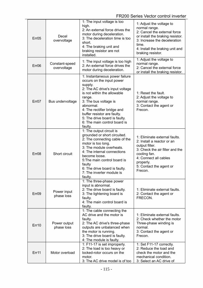
FR200 Series Vector control inverter
- 115 -
Err05 Decelovervoltage
1: The input voltage is toohigh.2: An external force drives themotor during deceleration.3: The deceleration time is tooshort.4: The braking unit andbraking resistor are notinstalled.
1: Adjust the voltage tonormal range.2: Cancel the external forceor install the braking resistor.3: Increase the decelerationtime.4: Install the braking unit andbraking resistor.
Err06 Constant-speedovervoltage
1: The input voltage is too high2: An external force drives themotor during deceleration.
1: Adjust the voltage tonormal range.2: Cancel the external forceor install the braking resistor.
Err07 Bus undervoltage
1: Instantaneous power failureoccurs on the input powersupply.2: The AC drive's input voltageis not within the allowablerange.3: The bus voltage isabnormal.4: The rectifier bridge andbuffer resistor are faulty.5: The drive board is faulty.6: The main control board isfaulty.
1: Reset the fault.2: Adjust the voltage tonormal range.3: Contact the agent orFrecon.
Err08 Short circuit
1: The output circuit isgrounded or short circuited.2: The connecting cable of themotor is too long.3: The module overheats.4: The internal connectionsbecome loose.5:The main control board isfaulty6: The drive board is faulty.7: The inverter module isfaulty.
1: Eliminate external faults.2: Install a reactor or anoutput filter.3: Check the air filter and thecooling fan.4: Connect all cablesproperly.5: Contact the agent orFrecon.
Err09 Power inputphase loss
1: The three-phase powerinput is abnormal.2: The drive board is faulty.3: The lightening board isfaulty.4: The main control board isfaulty.
1: Eliminate external faults.2: Contact the agent orFRECON.
Err10 Power outputphase loss
1: The cable connecting theAC drive and the motor isfaulty.2: The AC drive's three-phaseoutputs are unbalanced whenthe motor is running.3: The drive board is faulty.4: The module is faulty.
1: Eliminate external faults.2: Check whether the motorThree-phase winding isnormal.3: Contact the agent orFrecon.
Err11 Motor overload
1: F11-17 is set improperly.2: The load is too heavy orlocked-rotor occurs on themotor.3: The AC drive model is of too
1: Set F11-17 correctly.2: Reduce the load andcheck the motor and themechanical condition.3: Select an AC drive of
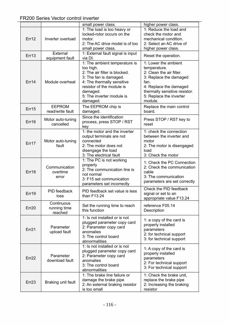
FR200 Series Vector control inverter
- 116 -
small power class. higher power class.
Err12 Inverter overload
1: The load is too heavy orlocked-rotor occurs on themotor.2: The AC drive model is of toosmall power class.
1: Reduce the load andcheck the motor andmechanical condition.2: Select an AC drive ofhigher power class.
Err13 Externalequipment fault
1: External fault signal is inputvia DI. Reset the operation.
Err14 Module overheat
1: The ambient temperature istoo high.2: The air filter is blocked.3: The fan is damaged.4: The thermally sensitiveresistor of the module isdamaged.5: The inverter module isdamaged.
1: Lower the ambienttemperature.2: Clean the air filter.3: Replace the damagedfan.4: Replace the damagedthermally sensitive resistor.5: Replace the invertermodule.
Err15 EEPROMread/write fault
The EEPROM chip isdamaged.
Replace the main controlboard.
Err16 Motor auto-tuningcancelled
Since the identificationprocess, press STOP / RSTkey
Press STOP / RST key toreset
Err17 Motor auto-tuningfault
1: the motor and the inverteroutput terminals are notconnected2: The motor does notdisengage the load3: The electrical fault
1: check the connectionbetween the inverter andmotor2: The motor is disengagedload3: Check the motor
Err18Communication
overtimeerror
1: The PC is not workingproperly2: The communication line isnot normal3: F15 set communicationparameters set incorrectly
1: Check the PC Connection2: Check the communicationcable3: The communicationparameters are set correctly
Err19 PID feedbackloss
PID feedback set value is lessthan F13.24
Check the PID feedbacksignal or set to anappropriate value F13.24
Err20Continuousrunning time
reached
Set the running time to reachthis function
reference F05.14Description
Err21 Parameterupload fault
1: Is not installed or is notplugged parameter copy card2: Parameter copy cardanomalies3: The control boardabnormalities
1: a copy of the card isproperly installedparameters2: for technical support3: for technical support
Err22 Parameterdownload fault
1: Is not installed or is notplugged parameter copy card2: Parameter copy cardanomalies3: The control boardabnormalities
1: A copy of the card isproperly installedparameters2: For technical support3: For technical support
Err23 Braking unit fault
1: The brake line failure ordamage the brake pipe2: An external braking resistoris too small
1: Check the brake unit,replace the brake pipe2: Increasing the brakingresistor
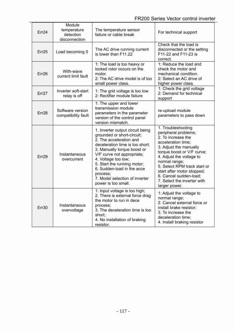
FR200 Series Vector control inverter
- 117 -
Err24
Moduletemperature
detectiondisconnection
The temperature sensorfailure or cable break For technical support
Err25 Load becoming 0 The AC drive running currentis lower than F11.22
Check that the load isdisconnected or the settingF11-22 and F11-23 iscorrect.
Err26 With-wavecurrent limit fault
1: The load is too heavy orlocked rotor occurs on themotor.2: The AC drive model is of toosmall power class.
1: Reduce the load andcheck the motor andmechanical condition.2: Select an AC drive ofhigher power class.
Err27 Inverter soft-startrelay is off
1: The grid voltage is too low2: Rectifier module failure
1: Check the grid voltage2: Demand for technicalsupport
Err28 Software versioncompatibility fault
1: The upper and lowertransmission moduleparameters in the parameterversion of the control panelversion mismatch.
re-upload moduleparameters to pass down
Err29 Instantaneousovercurrent
1. Inverter output circuit beinggrounded or short-circuit;2. The acceleration anddeceleration time is too short;3. Manually torque boost orV/F curve not appropriate;4. Voltage too low;5. Start the running motor;6. Sudden-load in the acceprocess;7. Model selection of inverterpower is too small.
1. Troubleshootingperipheral problems;2. To increase theacceleration time;3. Adjust the manuallytorque boost or V/F curve;4. Adjust the voltage tonormal range;5. Select RPM track start orstart after motor stopped;6. Cancel sudden-load;7. Select the inverter withlarger power.
Err30 Instantaneousovervoltage
1: Input voltage is too high;2. There is external force dragthe motor to run in deceprocess;3. The deceleration time is tooshort;4. No installation of brakingresistor.
1: Adjust the voltage tonormal range;2. Cancel external force orinstall brake resistor;3. To increase thedeceleration time;4. Install braking resistor
FR200 Series Vector control inverter
- 118 -
Chapter 8 Maintenance and Inspection
8.1 InspectionFrequency semiconductor devices, passive electronic components, and the movement device is
configured, these devices have life, even under normal working conditions, if over the useful life, somedevices may have characteristic changes or failure. In order to prevent this phenomenon leads tofailure and must be checked daily, periodic inspection, parts replacement and other preventativemaintenance checks. After the machine installation is recommended every 3 to 4 months to conductan inspection. If any of the following situations, please check to shorten the cycle.
High-temperature, high-altitude environment;Frequent starting and stopping the environment;The presence of AC power or load greater volatility environment;Environment existed large vibration or shock;The existence of environmental dust, metal dust, salt, sulfuric acid, chlorine element;Storage environment is very bad.
8.1.1 Daily inspectionTo avoid damage and shorten the life of the inverter, please confirm the following items daily.
item contents Strategies
Power supply
Check the supply voltage meets therequirements phase power supplyand the presence of thephenomenon.
Press nameplate asked to solve.
Surroundings Installation environment meets therequirements of Table 3-1.
Confirm the source and properlyresolve
Cooling SystemWhether the inverter and the motoris abnormal discoloration heatingand cooling fan status.
Confirm whether the overload,tighten the screws, if the inverterheatsink fan is dirty confirmwhether the stall.
Motor Whether the motor is abnormalvibration and abnormal noise.
Tightening mechanical andelectrical connections and dolubricated mechanical parts.
Load conditionsInverter output current is higher thanthe rating of the motor or inverterand lasted for some time.
Confirm whether there is anoverload condition occurs confirmthe correct drive selection
Note: Do not relate jobs in the state power is turned on, otherwise there is danger of electricshock to cause death. When conducting related operations, turn off the power and make sure themain circuit DC voltage has dropped to a safe level, five minutes before the related operations.8.1.2 Regularly check
Under normal circumstances, every three months to four months to conduct a periodic inspectionis appropriate, but in the actual case, combined with the use of each machine and the workingenvironment, to determine the actual inspection cycle.
FR200 Series Vector control inverter
- 119 -
item contents Strategies
Overall Insulation resistance check; environmental inspections.
fastening and replace bad parts; Clean improving operatingenvironment.
Electricalconnection
Are there wires and connectionportion discolored insulation fordamage, cracks, discoloration andaging signs; connection terminals for wear,damage, loose; ground checks.
Replace damaged wires; tighten loose terminals andreplace the damaged terminal; measure ground resistance andtighten the corresponding groundterminal.
Mechanicalconnection
whether there is abnormal vibrationand noise, fixed loose.
tightening, lubrication,replacement of bad parts.
Semiconductor devices
Are stained with dirt and dust; Are there significant changes inappearance.
Clean the operatingenvironment; Replace damaged parts.
Electrolyticcapacitor
whether the leaks, discoloration,cracking, safety is exposed, swelling,cracking or leakage.
Replace damaged parts.
Peripheralequipment
peripherals appearance andinsulation inspection.
Clean Environment replacedamaged parts.
Printed circuitboard
Are there odor, discoloration, severerust connector is correct and reliable.
Fastening; Clean the printed circuit board; Replace damaged printed circuitboard.
CoolingSystem
whether the cooling fan is broken andstall phenomenon; fins are not stained with garbage anddirt, dirty; air intake and exhaust ports areclogged or contaminated with foreignmatter.
Clean the operatingenvironment; Replace damaged parts.
Keyboard Are there broken keyboard anddisplay incomplete phenomenon. Replace damaged parts.
Motor The motor is abnormal vibration andabnormal noise.
fastening mechanical andelectrical connections, and themotor shaft lubrication.
Note: Do not relate jobs in the state power is turned on, otherwise there is danger of electricshock to cause death. When conducting related operations, turn off the power and make sure the maincircuit DC voltage has dropped to a safe level, five minutes before the related operations.
8.2 MaintenanceAll equipment, parts are all life, the right to life has been extended maintenance, but the damage
cannot be resolved equipment, devices, according to the requirements of life reached or are about toreach the end of the device to be replaced.
Part name Life CycleFan 2 to 3 years
Electrolytic capacitor 4 to 5 yearsPrinted circuit board 8 to 10 years
8.2.1 FanWhen replacing the cooling fan, use the original fan, buy original fan, and please contact the
dealer where you purchased the product or the company's sales department. Drive is equipped with aplurality of cooling fan models. For a number of cooling fans with inverter, To maximize the useful life ofthe product, when changing the cooling fan to simultaneously replace all the fans.

FR200 Series Vector control inverter
- 120 -
Fan Removal Method1. Under pressure Figure 8-1 (a) shows a fan elastic snaps, while a little harder to pull out in
parallel, remove the fan cover from the Inverter.2.Figure 8-1 (b) shown in order to come up with the fan cover and fan, and then press the fan as
shown in the medial elastic snap lead terminal, while a little harder to pull the fan lead terminal.
Figure 8-1 (a) Remove the fan covers Figure 8-1 (b) Remove the fanFan Installation1.Figure 8-2 (a) shown in finger pressure to the inside of the fan under the lead terminal elastic
snaps, while a little harder vertically into the lead terminal, and then fan vertically into the slot.2. Figure 8-2 (b), (c) as shown in the fan shroud assembly ramp into the hole at one end and the
other end to snap into place.
Figure 8-2 (a) Install the fan leads Figure 8-2 (b) Install the fan cover Figure 8-2 (c) fixed in placeNote:
1, do not related jobs in the state power is turned on, otherwise there is danger of electric shock tocause death. When conducting related operations, turn off the power and make sure the main circuitDC voltage has dropped to a safe level, five minutes before the related operations.
2, the drive to work due to the loss caused by the heat sink temperature, in order to prevent burns,do not touch the heat sink fins must be confirmed sufficiently cooled to a safe temperature below thenreplace the cooling fan.
3, in order to ensure that the inverter can maximize performance, please use the original fan.8.2.2 Other Devices
Replacement of other devices to maintain familiarity with technology and products are very strictand must go through rigorous testing to be put into use after the replacement, so I do not recommendthe user to replace the other internal components, if indeed need to be replaced, please contact thedealer where you purchased the product or our sales department.
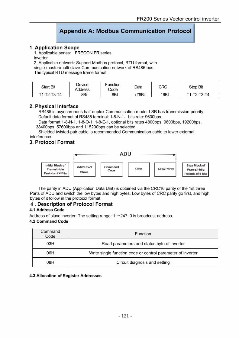
FR200 Series Vector control inverter
- 121 -
Appendix A: Modbus Communication Protocol
1. Application Scope1. Applicable series: FRECON FR seriesinverter2. Applicable network: Support Modbus protocol, RTU format, withsingle-master/multi-slave Communication network of RS485 bus.The typical RTU message frame format:
Start Bit DeviceAddress
FunctionCode Data CRC Stop Bit
T1-T2-T3-T4 8Bit 8Bit n*8Bit 16Bit T1-T2-T3-T4
2. Physical InterfaceRS485 is asynchronous half-duplex Communication mode. LSB has transmission priority.Default data format of RS485 terminal: 1-8-N-1,bits rate: 9600bps.Data format 1-8-N-1, 1-8-O-1, 1-8-E-1, optional bits rates 4800bps, 9600bps, 19200bps,
38400bps, 57600bps and 115200bps can be selected.Shielded twisted-pair cable is recommended Communication cable to lower external
interference.3. Protocol Format
The parity in ADU (Application Data Unit) is obtained via the CRC16 parity of the 1st threeParts of ADU and switch the low bytes and high bytes. Low bytes of CRC parity go first, and highbytes of it follow in the protocol format.4. Description of Protocol Format4.1 Address CodeAddress of slave inverter. The setting range: 1~247, 0 is broadcast address.4.2 Command Code
CommandCode Function
03H Read parameters and status byte of inverter
06H Write single function code or control parameter of inverter
08H Circuit diagnosis and setting
4.3 Allocation of Register Addresses
FR200 Series Vector control inverter
- 122 -
name Description
Function Code(F00.00~U01.99)
High byte function code group number, F00~F31, U00, U01,respectively, corresponding to the high byte address is 00H~1FH, 30H,31H.Low byte of the group function code number, from 0 to 99 correspondingto the low byte address is 00H~63H.For example: Modify F01.02 function code value, no power-down whenstoring the corresponding register address (referred to as RAM address)to 0102H.EEPROM is frequently modified, will reduce the life of the EEPROM. Ifyou modify the value of the function code-down storage needs, you canmake this function code is the highest position a high address. Note thatthis address is only to write, not read.For example: Modify F01.02 function code value, and the correspondingneed to power down when storing the register address (referred to asEEPROM address) to 8102H.
Function code group RAM address high byte EEPROM address high byteF00 0x00 0x80F01 0x01 0x81F02 0x02 0x82…… …… ……F30 0x1E 0x9EF31 0x1F 0x9F
U00 (Read Only) 0x30 --U01 (Read Only) 0x31 --
4.4 Address and control command functions: (write only)Command word address Command Function
2000H
0001: Forward run0002: Reverse Run0003: Inching Forward0004: Reverse Jog0005: Slowdown stop0006: freewheel0007: Fault reset
2001H Communication setting frequency (0~Fmax (Unit: 0.01Hz))2002H PID given range (0 to 1000, 1000 corresponds to 100.0%)2003H PID feedback range (0~1000, 1000 corresponds to 100.0%)
2004H Torque set point (-3000~3000, 1000 corresponds to 100.0%motor rated current)
2005~20FF Retention
FR200 Series Vector control inverter
- 123 -
4.5 The status and function of the read address Description: (read only)Status word address functional status word
2100H
0000H: parameter setting0001H: slave run0002H: JOG operation0003H: learning run0004H: Slave parking0005H: JOG parking0006H: Fault Status
2101H
Bit0: 0 are given effective1 Given negative effective
Bit1:0 frequency output Forward1 frequency output inversion
Bit2~3:00 Keyboard start-stop01 terminal start-stop10 start-stop communication11 Reserved
Bit4:0 Factory password is invalid1 factory password is valid
Bit5:0 user password is invalid1 valid user password
Bit6~7:00 basic function code group01 user-defined function code group10 different functions with the factory default code group11 Others
5.Explanation of CommandCommand code 0x03: Read parameter and status of inverter.
ADU Item Byte No. RangeMaster requests:Address of slave 1 0~127Command Code 1 0x03Register start address 2 0x0000~0xFFFFThe number of register 2 0x0000~0x0008CRC parity(Low bytes go first) 2Slave responds :Address of slave 1 The local addressCommand Code 1 0x03Register start address 1 2∗number of registersThe number of register 2∗number of registersCRC parity 2Remarks: Read maximum 8 function codes consecutively.
FR200 Series Vector control inverter
- 124 -
Command code 0x06: Write single function code or control parameter of inverter.ADU Item Byte No. Range
Master requests:Address of slave 1 0~127Command Code 1 0x06Register start address 2 0x0000~0xFFFFThe number of register 2 0x0000~0xFFFFCRC parity 2Slave responds :Address of slave 1 The local addressCommand Code 1 0x06Register start address 2 0x0000~0xFFFFThe number of register 2 0x0000~0xFFFFCRC parity 2
Command code 0x08: Circuit Diagnosis and SettingADU Item Byte No. Range
Master requests:Address of slave 1 0~127Command Code 1 0x08Register start address 2 0x0000~0xFFFFThe number of register 2CRC parity 2Slave responds :Address of slave 1 The local addressCommand Code 1 0x08Register start address 2 0x0000~0xFFFFThe number of register 2CRC parity 2
Remarks: Command code 0x08 is only for circuit check.6.CRC Parity
Sending equipment calculates CRC parity value first, and then attaches it to the sendingmessage. Upon receipt of the message, receiving equipment will calculate CRC parity value again,and compare the operation result with received CRC parity value. If the two values are different, itindicates that there is error during transmission.Calculation process of CRC parity:1. Define a CRC parity register, and initialize it as FFFFH.2. Conduct XOR calculation between the first byte of sending message and the value of CRC parityregister, and then upload the result to CRC parity register. Start from address code, the start bit andstop bit will not be calculated.3. Collect and check LSB (the least significant bit of CRC parity register).4. If LSB is 1, shift each bit of CRC parity register rightwards by 1 bit, the highest bit filled with 0.Conduct XOR calculation between the value of CRC register and A001H, and then upload the result toCRC parity register.5. If LSB is 0, shift each bit of CRC parity register rightwards by 1 bit, the highest bit filled with 0.6. Repeat steps 3, 4 and 5 until completing 8 rounds of shifting.7. Repeat steps 2, 3, 4, 5 and 6, and process the next byte of sending message. Repeat above processcontinuously until each byte of sending message is processed.8. CRC parity date will be saved in CRC parity register after calculation.9. LUT (Look-up table) method is to obtain CRC parity in the system with limited time resources.Simple CRC functions as shown in following (C language Programming):
FR200 Series Vector control inverter
- 125 -
unsigned int CRC_Cal_Value (unsigned char ∗Data, unsigned char Length)
unsigned int crc_value = 0xFFFF;int i = 0;while (Length--)
crc_value ^= ∗Data++;for (i=0; i<8; i++)
if (crc_value & 0x0001)
crc_value = (crc_value>>1) ^ 0xa001;else
crc_value = crc_value>>1;
return (crc_value);
7.Error Message ResponseInverter will send an error message report when the master sends error data or inverter receives
the error data due to the external interference.When Communication error occurs, slave combines the highest bit 1 of command code and error
code as the response to the master.Responding data frame format when errors happened in Communication:
ADU Item Byte No. RangeError response:Address of slave 1 0~127Error command code 1 The highest bit 1 of command codeError code 1 0x01~0x13CRC parity(Low bytes go first) 2
Responding command code at normal Communication and error CommunicationResponding Command Code at Normal
CommunicationResponding Command Code at Error
Communication03H 83H06H 86H08H 88H
Description of Error Code:error Description error Description
01H Exceptional commandcode 03H Illegal Data
02H Exceptional data address 04H Operation failedFor example, for U00.00 write data 50.00HZ frequency. The host sends the data frame (hex):
01H 06H 30H 00H 13H 88H 8BH 9CHBecause F00.00 is read only, inverter responds error message. Inverter responds data frame inhexadecimal format:
01H 86H 02H C3H A1HCommand code is 86H in error message, the highest bit 1 of 06H. If error code detail is 11H, it meansthe parameter is read only.
After responding to the error data receipt, master can revise the responding program viaresending data frame or based on the error message responded by the inverter.
FR200 Series Vector control inverter
- 126 -
8. Illustration1, No. 01 reads the output frequency value (U00.00), returned 5000, that 50.00Hz.To send data:01 03 30 00 00 01 8B 0AThe received data is:01 03 02 13 88 B5 122, No. 01 Drive communication given frequency 30.00Hz, send the data content of 3000.To send data:01 06 20 01 0B B8 D4 88The received data is:01 06 20 01 0B B8 D4 883, communications sent on the 1st drive forward run command, write to the address 2000H 01To send data:01 06 20 00 00 01 43 CAThe received data is:01 06 20 00 00 01 43 CA4, No. 01 communications sent inverter deceleration stop command, the address to write to
2000H 05To send data:0,106,200,000,054,209The received data is:0,106,200,000,054,209
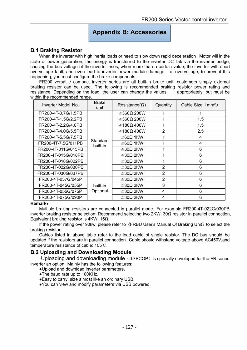
FR200 Series Vector control inverter
- 127 -
Appendix B: Accessories
B.1 Braking ResistorWhen the inverter with high inertia loads or need to slow down rapid deceleration,Motor will in the
state of power generation, the energy is transferred to the inverter DC link via the inverter bridge,causing the bus voltage of the inverter rises, when more than a certain value, the inverter will reportovervoltage fault, and even lead to inverter power module damage of overvoltage, to prevent thishappening, you must configure the brake components.
FR200 versatile compact inverter series are all built-in brake unit, customers simply externalbraking resistor can be used. The following is recommended braking resistor power rating andresistance. Depending on the load, the user can change the values appropriately, but must bewithin the recommended range.
Inverter Model No. Brakeunit Resistance(Ω) Quantity Cable Size(mm2)
FR200-4T-0.7G/1.5PB
Standardbuilt-in
≧360Ω 200W 1 1FR200-4T-1.5G/2.2PB ≧360Ω 200W 1 1.5FR200-4T-2.2G/4.0PB ≧180Ω 400W 1 1.5FR200-4T-4.0G/5.5PB ≧180Ω 400W 2 2.5FR200-4T-5.5G/7.5PB ≧60Ω 1KW 1 4FR200-4T-7.5G/011PB ≧60Ω 1KW 1 4FR200-4T-011G/015PB ≧30Ω 2KW 1 6FR200-4T-015G/018PB ≧30Ω 2KW 1 6FR200-4T-018G/022PB ≧30Ω 2KW 1 6FR200-4T-022G/030PB ≧30Ω 2KW 2 6FR200-4T-030G/037PB ≧30Ω 2KW 2 6FR200-4T-037G/045P
built-inOptional
≧30Ω 2KW 2 6FR200-4T-045G/055P ≧30Ω 2KW 3 6FR200-4T-055G/075P ≧30Ω 2KW 4 6FR200-4T-075G/090P ≧30Ω 2KW 4 6
Remark:Multiple braking resistors are connected in parallel mode. For example FR200-4T-022G/030PB
inverter braking resistor selection: Recommend selecting two 2KW, 30Ω resistor in parallel connection,Equivalent braking resistor is 4KW, 15Ω.
If the power rating over 90kw, please refer to《FRBU User's Manual Of Braking Unit》to select thebraking resistor.
Cables listed in above table refer to the lead cable of single resistor. The DC bus should beupdated if the resistors are in parallel connection. Cable should withstand voltage above AC450V,andtemperature resistance of cable: 105.B.2 Uploading and Downloading Module
Uploading and downloading module(0.7BCOP)is specially developed for the FR seriesinverter an option, Mainly has the following features:
Upload and download inverter parameters.The baud rate up to 100KHz.Easy to carry, size almost like an ordinary USB.You can view and modify parameters via USB powered.
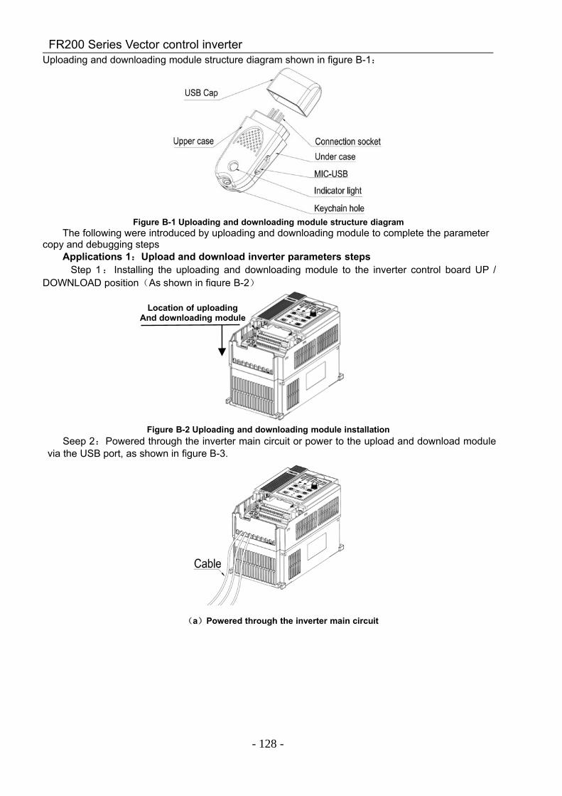
FR200 Series Vector control inverter
- 128 -
Uploading and downloading module structure diagram shown in figure B-1:
Figure B-1 Uploading and downloading module structure diagramThe following were introduced by uploading and downloading module to complete the parameter
copy and debugging stepsApplications 1:Upload and download inverter parameters steps
Step 1: Installing the uploading and downloading module to the inverter control board UP /DOWNLOAD position(As shown in figure B-2)
Figure B-2 Uploading and downloading module installationSeep 2:Powered through the inverter main circuit or power to the upload and download module
via the USB port, as shown in figure B-3.
(a)Powered through the inverter main circuit
Location of uploadingAnd downloading module
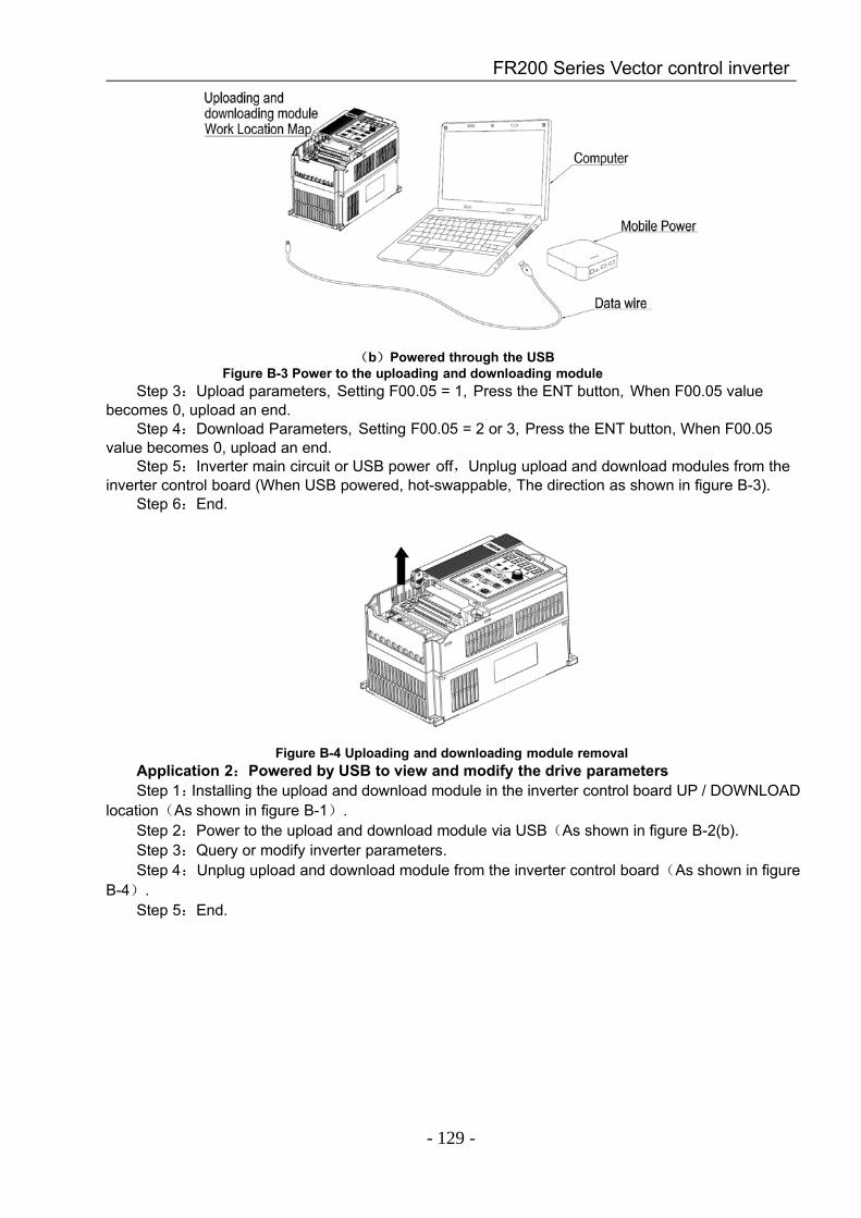
FR200 Series Vector control inverter
- 129 -
(b)Powered through the USBFigure B-3 Power to the uploading and downloading module
Step 3:Upload parameters, Setting F00.05 = 1, Press the ENT button, When F00.05 valuebecomes 0, upload an end.
Step 4:Download Parameters, Setting F00.05 = 2 or 3, Press the ENT button, When F00.05value becomes 0, upload an end.
Step 5:Inverter main circuit or USB power off,Unplug upload and download modules from theinverter control board (When USB powered, hot-swappable, The direction as shown in figure B-3).
Step 6:End.
Figure B-4 Uploading and downloading module removalApplication 2:Powered by USB to view and modify the drive parametersStep 1:Installing the upload and download module in the inverter control board UP / DOWNLOAD
location(As shown in figure B-1).Step 2:Power to the upload and download module via USB(As shown in figure B-2(b).Step 3:Query or modify inverter parameters.Step 4:Unplug upload and download module from the inverter control board(As shown in figure
B-4).Step 5:End.