Embed Size (px)
Citation preview
DRAFT MODIFIED ADOPTION
IS 10613 : 2014
1
(Amalgamating IS 10616: 1983)
भारतीय मानक
साइककल – साइककल क ललए सरषा अपषाए
Indian Standard
CYCLES — SAFETY REQUIREMENTS FOR
BICYCLES
( Second Revision )
ICS 43.150
@ BIS 2014
B U R E A U O F I N D I A N S T A N D A R D S MANAK BHAVAN, 9 BAHADUR SHAH ZAFAR MARG
NEW DELHI 110002
April 2014 Price Group
Bicycles Sectional Committee, TED 16
DRAFT MODIFIED ADOPTION
IS 10613 : 2014
2
‘FOREWORD
This Indian Standard (First Revision), a modified adoption of ‘ISO 4210 : 1996 Cycles — Safety
requirements for bicycles’ issued by the International Organization for Standardization ( ISO ) was adopted by the Bureau of Indian Standards on the recommendations of the Bicycles Sectional
Committee and approval of the Transport Engineering Division Council.
IS 10613:1983 ‘Specification for bicycles’ was first published in 1983. Methods of tests were
covered in IS 10616:1983 ‘Methods of tests for bicycle and sub-assemblies’. This revision has been undertaken by amalgamating it with IS 10613, in order to harmonize withIndian Standard ISO
4210:1996. This standard was revised and published in 2004 as identical to ISO 4210 : 1996. Since
the requirements of Retro-reflective tapes are not specified in ISO standard at present, the dual
number status of this standard has been changed to modified adoption for incorporating the
requirements for retro-reflective tapes in accordance with statutory regulations issued by the
regulatory body ‘Ministry of Road Transport & Highways’.
In this revision (modified adoption) the following changes are considered:
1. References to the available Indian standards (Technically equivalent) are considered in
place of ISO standards.
2. Additional requirement of Retro-reflective tapes, their sizes and placement are considered
in this draft standard as an additional clause.
3. Provisions of ISO 6742-1 and ISO 7636 were already reviewed by the technical committee
and decided that they are acceptable for use in conjunction with the earlier adopted ISO
4210: 1996, hence they are also considered even in this modified adoption.
4. Marking details are modified in line with BIS certification requirements.
For the purpose of deciding whether a particular requirement of this standard is complied with. the
final value. observed or calculated, expressing the result of a test or analysis, shall be rounded off
in accordance with IS 2 : 1960 ‘Rules for rounding off numerical values ( revised )’. The number of
significant places retained in the rounded off value should be the same as that of the specified value
in this standard.
IS 10613 : 2014
DRAFT MODIFIED ADOPTION
IS 10613 : 2014
3
Indian Standard
CYCLES — SAFETY REQUIREMENTS FOR
BICYCLES
( Second Revision )
SECTION 1: GENERAL
1.1 Scope
This Indian Standard specifies safety and performance requirements for the design, assembly and
testing of bicycles and sub-assemblies, and lays down guidelines for instructions on the use and
care of bicycles.
It applies to bicycles intended for use on public roads, and on which the saddle can be adjusted to
provide a saddle height of 635 mm or more.
It does not apply to specialized types of bicycle such as tradesmen’s delivery bicycles, tandems, toy
bicycles and bicycles designed and equipped for use in sanctioned competitive events.
1.2 References
The following standards contain provisions, which, through reference in this text, constitute
provisions of this Indian Standard. At the time of publication, the editions indicated were valid. All
standards are subject to revision, and parties to agreements based on this Standard are encouraged
to investigate the possibility of applying the most recent editions of the standards listed below:
IS/ ISO Number Title
624:2003 Bicycles - Rims - Specification (fourth revision)
| ISO 5775-2:1996
1283:1995 Bicycles – Freewheels and chains - Specification (second revision)
2414: 2005 Cycle and rickshaw pneumatic tyres - Specification (fourth revision)
ISO 6742-1:1987 Cycles — Lighting and retro-reflective devices — Photometric and physical
requirements — Part 1: Lighting equipment.
IS/ISO 6742-2:1985 Cycles - Lighting and retro-reflective devices - Photometric and physical
requirements Part 2: Retro-reflective devices (Superseding IS 7699)
14221: 1995 Automotive vehicles — Retro-reflective sheets and tapes – Specification’
ISO 7636:1984 Bels for bicycles and mopeds — Technical specifications.

DRAFT MODIFIED ADOPTION
IS 10613 : 2014
4
1.3 Definitions
For the purposes of this Indian Standard, the following definitions apply.
1.3.1 Cycle: Any vehicle that has at least two wheels and is propelled solely by the muscular
energy of the person on that vehicle, in particular by means of pedals.
1.3.2 Bicycle: Two-wheeled cycle.
1.3.3 Delivery bicycle: Bicycle designed for the primary purpose of carrying goods.
1.3.4 Tandem: Bicycle with saddles for two or more riders, one behind the other.
1.3.5 Saddle Height: Dimension from the ground plane to the top of the saddle, measured in the
centre of the seating area normal to the ground plane when the bicycle is upright.
1.3.6 Braking Distance travelled by a bicycle between the commencement of braking (1.3.7) and
the
point at which the bicycle comes to rest.
1.3.7 Commencement Of Braking: Point on the test track at which the brake actuating mechanism
is moved from its rest position. In tests with two brakes, this point is determined by the first
mechanism to operate.
1.3.8 Gear Development Distance travel led by a bicycle during one revolution of the pedal cranks.
1.3.9 Exposed Protrusion: Protrusion that can be contacted by the central 75 mm of the lateral
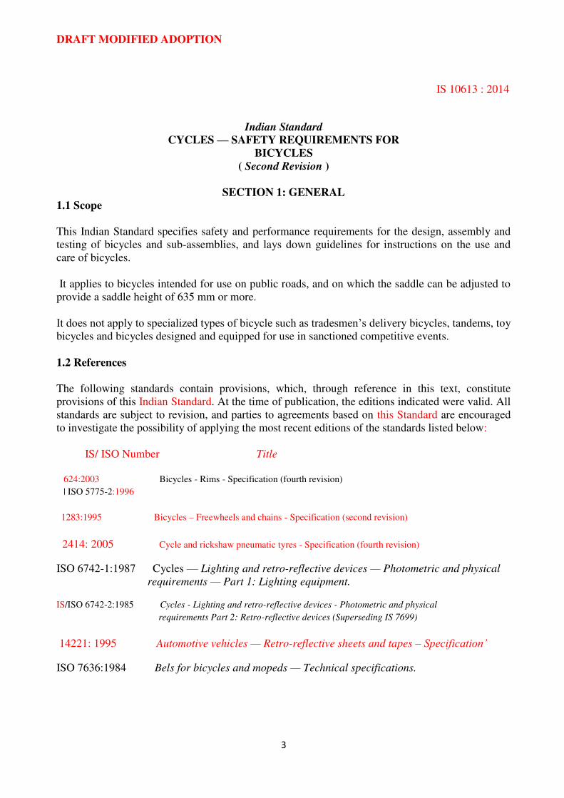
surface of a cylinder 250 mm long and 83 mm in diameter (simulating a limb). See figure 1.
1.3.10 (Pedal) Tread Surface: Surface of a pedal that is presented to the underside of the foot, the
design of which incorporates a slip-resistant characteristic.
1.3.11 Ferrous Component composed of structural members made entirely from ferrous materials
excluding any jointing media such as brazing materials or adhesives.
1.3.12 Non-Ferrous Component: Component composed of structural members made entirely from
non-ferrous materials excluding any jointing media such as adhesives.
NOTE— For the purposes of the choice of fatigue test forces, any component made from a mixture
of ferrous and nonferrous members shall be classified as non-ferrous.
1.3.13 Crank Assembly: Crank assembly for fatigue testing consists of the two cranks, the pedal
spindles, the bottom bracket spindle, and the first component of the drive system, e.g. chain wheel.
DRAFT MODIFIED ADOPTION
IS 10613 : 2014
5
SECTION 2
2.1 General
2.1.1 Sharp Edges
Exposed edges that could come into contact with the rider’s hands, legs, etc., during normal riding or normal handling and normal maintenance shall not be sharp.
2.1.2 Protrusions
Any rigid exposed protrusion longer than 8 mm after assembly shall terminate in a radius of not
less than 6, 3 mm. Such protrusions shall have a major end dimension greater than 12,7 mm and a
minor end dimension greater than 3,2 mm.
Figure 1 — Exposed protrusion test cylinder
There shall be no protrusions on the top tube of a bicycle frame between the saddle and a point 300
mm forward of the saddle, with the exception that control cables no greater than 6,4 mm in
diameter and cable clamps made from material no thicker than 4,8 mm may be attached to the top
tube.
Foam pads attached to the bicycle frame to act as protective cushions are permitted, provided that
the bicycle meets the requirements for protrusions when the pads are removed.
A screw thread that is an exposed protrusion (1.3.9) shall be limited to a protrusion length of one
major diameter of the screw beyond the internally threaded mating part.
DRAFT MODIFIED ADOPTION
IS 10613 : 2014
6
2.2 Brakes
2.2.1 Braking Systems
A bicycle shall be equipped with two braking systems. One shall operate on the front wheel and
one on the rear wheel. The braking systems shall operate without binding and shall be capable of
meeting the braking performance requirements of 2.2.5.
Brake blocks containing asbestos shall not be permitted.
2.2.2 Hand-Operated Brakes
2.2.2.1 Brake lever position
Hand brake levers for front and rear brakes, shall be positioned according to the legislation or
custom and practice’ of the country in which the bicycle is to be sold.
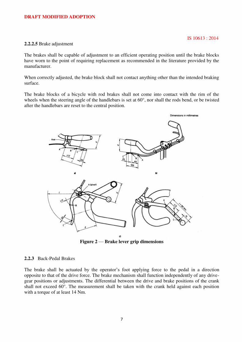
2, 2.2.2 Brake lever dimensions
The maximum grip dimension, d, measured between the outer surfaces of the brake lever and the
handlebar, or the handlebar grip or any other covering where present, shall not exceed 90 mm
between points A and B, and 100 mm between points B and C (see figure 2).
NOTE— The range of adjustment on the brake lever should permit these dimensions to be
obtained.
2.2.2.3 Attachment of brake assembly
The screws used to attach a brake assembly to the frame; fork or handlebar shall be provided with
suitable locking devices, for example a lock-washer, lock-nut or stiff-nut.
Cable pinch-bolts shall not sever any of the cable strands when assembled to the manufacturer’s instructions. In the event of a brake cable failing, no part of the brake mechanism shall
inadvertently inhibit the rotation of the wheel.
The cable end shall either be treated to prevent unravelling, protected with a cap that shall
withstand a removal force of 20 N or be otherwise treated to prevent unravelling.
2.2.2.4 Brake block assembly
The brake block shall be securely attached to the backing plate or holder and there shall be no
failure of the block assembly when tested by the method specified in 4.1. The brake system shall be
capable of meeting the strength test specified in 2.2.4.1 and the braking performance requirements
of 2.2.5.1 and 2.2.5.2 after completion of the test specified in 4.1.
DRAFT MODIFIED ADOPTION
IS 10613 : 2014
7
2.2.2.5 Brake adjustment
The brakes shall be capable of adjustment to an efficient operating position until the brake blocks
have worn to the point of requiring replacement as recommended in the literature provided by the
manufacturer.
When correctly adjusted, the brake block shall not contact anything other than the intended braking
surface.
The brake blocks of a bicycle with rod brakes shall not come into contact with the rim of the
wheels when the steering angle of the handlebars is set at 60°, nor shall the rods bend, or be twisted
after the handlebars are reset to the central position.
Figure 2 — Brake lever grip dimensions
2.2.3 Back-Pedal Brakes
The brake shall be actuated by the operator’s foot applying force to the pedal in a direction
opposite to that of the drive force. The brake mechanism shall function independently of any drive-
gear positions or adjustments. The differential between the drive and brake positions of the crank
shall not exceed 60°. The measurement shall be taken with the crank held against each position
with a torque of at least 14 Nm.
DRAFT MODIFIED ADOPTION
IS 10613 : 2014
8
2.2.4 Strength of Brake System
2.2.4.1 Hand-operated brakes
When tested by the method described in 4.2.1, there shall be no failure of the brake system or of
any component thereof.
2.2.4.2 Back-pedal brakes
When tested by the method described in 4.2.2, there shall be no failure of the brake system or any
component thereof.
2.2.5 Braking Performance
2.2.5.1 Braking under dry conditions
When tested by the method described in 4.3, a bicycle shall be brought to a smooth safe stop within
the relevant distances and from the relevant velocities given in table 1.
2.2.5.2 Braking under wet conditions
When tested by the method described in 4.3, a bicycle shall be brought to a smooth safe stop within
the relevant distances and from the relevant velocities given in table 1.
2.2.5.3 Extension levers
Where a bicycle is fitted with extension levers, separate tests shall be conducted for the operation
of the extension levers In addition to tests using the normal levers to which the extensions are
attached.
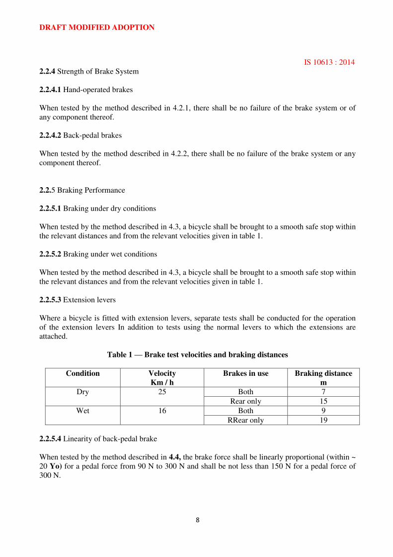
Table 1 — Brake test velocities and braking distances
Condition Velocity
Km / h
Brakes in use Braking distance
m
Dry 25 Both 7
Rear only 15
Wet 16 Both 9
RRear only 19
2.2.5.4 Linearity of back-pedal brake
When tested by the method described in 4.4, the brake force shall be linearly proportional (within ~
20 Yo) for a pedal force from 90 N to 300 N and shall be not less than 150 N for a pedal force of
300 N.
DRAFT MODIFIED ADOPTION
IS 10613 : 2014
9
2.3 Steering
2.3.1 Handlebars
The handlebars shall have an overall width between 350 mm and 700 mm. The vertical distance
between the top of the handlebar grips, when assembled to the highest riding position according to
the manufacturer’s instructions and the seat surface of the saddle in its lowest position shall not
exceed 400 mm.
The ends of the handlebars shall be fitted with handgrips or end plugs that will withstand a removal
force of 70 N.
2.3.2 Handlebar Stem
The handlebar stem shall contain a permanent mark that clearly indicates the minimum insertion
depth of the handlebar stem into the fork stem, or alternatively a positive and permanent means of
ensuring the minimum insertion depth shall be provided. The insertion mark, or insertion depth,
shall be not less than 2,5 times the shaft diameter from the lower end of the stem, and there shall be
at least one shaft diameter’s length of contiguous circumferential shaft material below the mark. An
insertion mark shall not affect the strength of the handlebar stem.
2.3.3 Expander Bolt For Handlebar Stem
The minimum failure torque of the bolt shall be at least 50 Y. greater than the manufacturer’s maximum tightening torque.
2.3.4 Steering Stability
The steering shall be free to turn through at least 60° either side of the straight-ahead position and
shall exhibit no tight spots, stiffness or slackness in the bearings when correctly adjusted.
A minimum of 25 % of the total mass of the bicycle and rider shall act on the front wheel when the
rider is holding the handlebar grips and sitting on the saddle, with the saddle and rider in their most
rearward positions.
Recommendations for steering geometry are given in annex B.
2.3.5 Strength of Steering Assembly
The handlebar stem shall be capable of withstanding without fracture the tests described in 4.5.1.1
and 4.5.1.2.
When tested by the method described in 4.5.2, there shall be no movement of the handlebar relative
to the stem.
When tested by the method described in 4.5.3, there shall be no movement of the handlebar stem
relative to the fork stem other than that movement required to take up tolerances before any locking
faces abut. Such movement shall not exceed 5°.
DRAFT MODIFIED ADOPTION
IS 10613 : 2014
10
2.3.6 Fatigue Test on Handlebar and Stem Assembly
When tested by the method described in 4.5.4, there shall be no fractures or visible cracks in the
handlebar or stem.
NOTE— It is recommended that standardized crack inspection methods are used, such as those
contained in ISO 3452. This recommendation applies to all crack test requirements in this Indian
Standard.
2.4 Frame-Fork Assembly
2.4.1 Impact Test (Falling Mass)
When tested by the method described in 4.6.1, there shall be no visible evidence of fracture, and
the permanent deformation of the assembly, measured between the centrelines of the wheel axles
(wheelbase), shall not exceed 40 mm.
2.4.2 Impact Test (Falling Frame-Fork Assembly)
When tested by the method described in 4.6.2, there shall be no visible evidence of fracture.
2.5 Front Fork
2.5.1 Means Of Location
The slots or other means of location for the front wheel axle within the front fork shall be such that
when the axle or cones are firmly abutting the top face of the slots, the front wheel remains central
within the front fork.
2.5.2 Fatigue Strength Of Fork
When tested by the method described in 4.6.3 there shall be no fracture or visible cracks on any
part of the fork.
2.6 Wheels
2.6.1 Rotational Trueness
Rotational trueness is defined in ISO 1101 in terms of circular run-out tolerance (axial). The run-
out tolerances given in 2.6.1.1 and 2.6.1.2 represent the maximum permissible variation of position
of the rim (i.e. full indicator reading) of a fully assembled wheel during one complete revolution
about the axle without axial movement.

DRAFT MODIFIED ADOPTION
IS 10613 : 2014
11
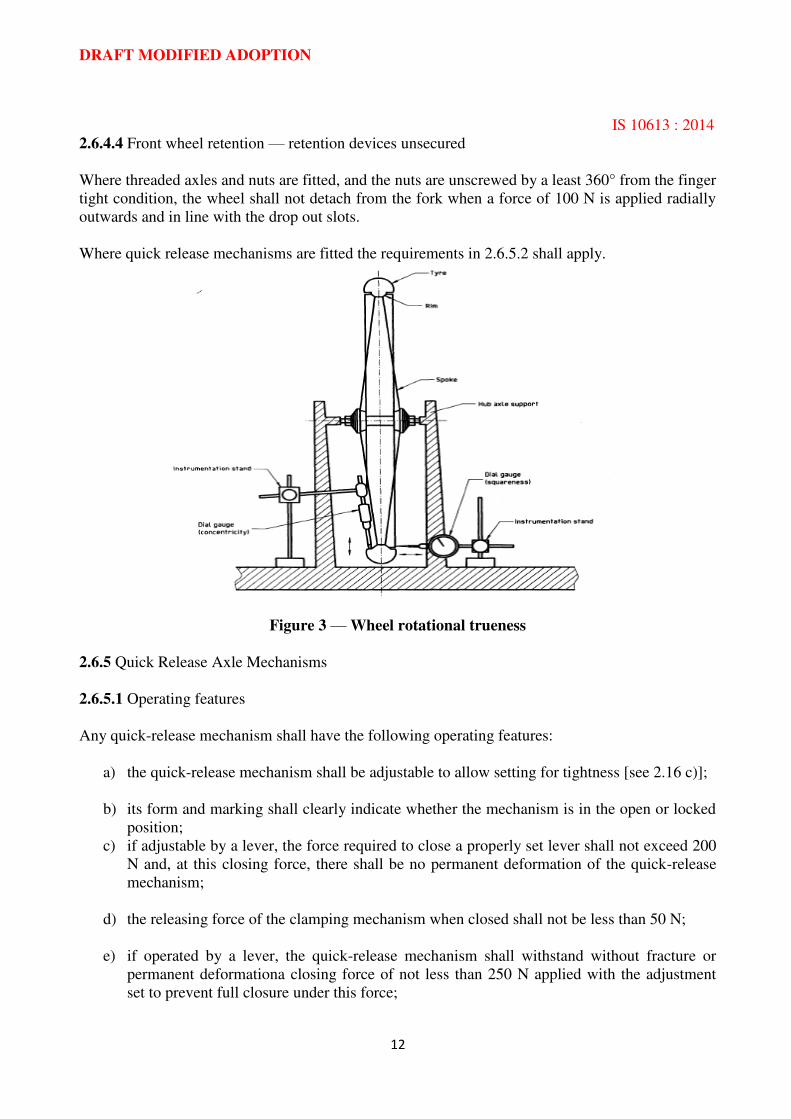
2.6.1.1 Concentricity tolerance
For bicycles equipped with rim brakes, the run-out shall not exceed 2 mm when measured
perpendicular to the axle at a suitable point along the rim. (See figure 3.)
For bicycles not equipped with rim brakes, the run-out shall not exceed 4 mm.
2.6.1.2 Squareness tolerance
For bicycles equipped with rim brakes, the run-out shall not exceed 2 mm when measured parallel
to the axle at a suitable point along the rim. (See figure 3.)
For bicycles not equipped with rim brakes, the run-out shall not exceed 4 mm.
2.6.2 Clearance
Alignment of the wheel assembly in a bicycle shall allow not less than 2 mm clearance between the
tyre and any frame or fork element.
2.6.3 Static Load Test
When a fully assembled wheel is tested by the method described in 4.7, there shall be no failure of
any of the components of the wheel, and the permanent deformation, measured at the point of
application of the force on the rim, shall not exceed 1,5 mm.
2.6.4 Wheel Retention
2.6.4.1 General
Wheels shall be secured to the bicycle frame and fork such that when adjusted to the
manufacturer’s recommendations they comply with 2.6.4.2, 2.6.4.3, 2.6.4.4 and 2.6.5.
Wheel nuts shall have a minimum removal torque of 70 % of the manufacturers’ recommended tightening torque. Where quick-release axle mechanisms are used they shall comply with 2.6.5.
2.6.4.2 Front wheel retention — retention devices secured
There shall be no relative motion between the axle and the front fork when a force of 2300 N is
applied symmetrically to either side of the axle for a period of 30s in the direction of the removal of
the wheel.
2.6.4.3 Rear wheel retention — retention devices secured
There shall be no relative motion between the axle and the frame when a force of 2300 N is applied
symmetrically to either side of the axle for a period of 30 s in the direction of the removal of the
wheel.
DRAFT MODIFIED ADOPTION
IS 10613 : 2014
12
2.6.4.4 Front wheel retention — retention devices unsecured
Where threaded axles and nuts are fitted, and the nuts are unscrewed by a least 360° from the finger
tight condition, the wheel shall not detach from the fork when a force of 100 N is applied radially
outwards and in line with the drop out slots.
Where quick release mechanisms are fitted the requirements in 2.6.5.2 shall apply.
Figure 3 — Wheel rotational trueness
2.6.5 Quick Release Axle Mechanisms
2.6.5.1 Operating features
Any quick-release mechanism shall have the following operating features:
a) the quick-release mechanism shall be adjustable to allow setting for tightness [see 2.16 c)];
b) its form and marking shall clearly indicate whether the mechanism is in the open or locked
position;
c) if adjustable by a lever, the force required to close a properly set lever shall not exceed 200
N and, at this closing force, there shall be no permanent deformation of the quick-release
mechanism;
d) the releasing force of the clamping mechanism when closed shall not be less than 50 N;
e) if operated by a lever, the quick-release mechanism shall withstand without fracture or
permanent deformationa closing force of not less than 250 N applied with the adjustment
set to prevent full closure under this force;
DRAFT MODIFIED ADOPTION
IS 10613 : 2014
13
f) the wheel retention with the quick-release mechanism in the clamped position shall be in
accordance with 2.6.4.2 and 2.6.4.3.
If applied to a lever, the forces specified in c), d) and e) shall be applied 5 mm from the tip end of
the lever.
2.6.5.2 Removal
It shall be possible to remove and replace the wheel without disturbing the preset condition when
secondary devices are not present. When a secondary device is present, and the quick release lever
is fully open and the brake system is disconnected or released, the wheel shall not detach from the
fork when a force of 100 N IS applied to the wheel radially outward and in line with the drop out
slots.
NOTE— It is recommended that it be possible to remove and replace the wheel without disturbing
the preset condition when secondary devices are present.
2.7 Rims, Tyres and Tubes
Non-moulded tyres are excluded from the requirements of 2.7.1 and 2.7.2.
2.7.1 Inflation Pressure
The maximum inflation pressure recommended by the manufacturer shall be moulded on the
sidewall of the tyre so as to be readily visible when the latter is assembled on the wheel.
2.7.2 Compatibility
Tyres shall comply with the requirements of IS 2414: 2005 and rims shall comply with the
requirements of IS 624:2003 / ISO 5775-2:1996. The tyre and tube shall be compatible with the rim
design. When inflated to 110 % of the maximum inflation pressure for a period of not less than 5
rein, the tyre shall remain intact on the rim.
2.8 Pedals and Pedal/Crank Drive System
2.8.1 Pedal Tread
2.8.1.1 The tread surface of a pedal shall be secured against movement within the pedal assembly.
2.8.1.2 Pedals intended to be used without toe-clips, or for optional use with toe-clips, shall have
a) tread surfaces on the top and bottom surfaces of the pedal, or
b) b) a definite preferred position that automatically presents the tread surface to the rider’s foot.
DRAFT MODIFIED ADOPTION
IS 10613 : 2014
14
2.8.1.3 Pedals designed to be used onlv with toe-clim or shoe retention devices shall have toe-clips
or shoe retention devices securely attached and need not comply with the requirements given in
2.8.1.2 a) and b).
2.8.2 Pedal Clearance
2.8.2.1 Ground clearance
With the bicycle unladen, the pedal at its lowest point and the tread surface of the pedal parallel to
the ground and uppermost where it has only one tread surface, the bicycle shall be capable of being
leaned over at an angle of 25° from the vertical before any part of the pedal touches the ground.
When a bicycle is equipped with a sprung suspension, this measurement shall be taken with the
suspension in a depressed position such as would be caused by a rider weighing 85 kg.
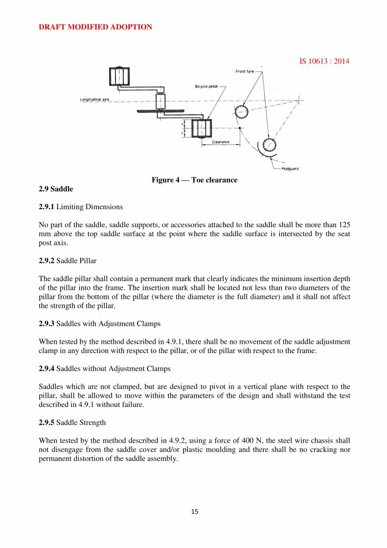
2.8.2.2 Toe clearance
Bicycles not equipped with positive foot-retaining devices (such as toe-clips) shall have at least 89
mm clearance between the pedal and the front tyre or mudguard [when turned to any position). The
clearance shall be measured forward and parallel to the longitudinal axis of the bicycle from the
centre of either pedal to the arc swept by the tyre or mudguard, whichever results in the least
clearance. (See figure 4.)
Where a bicycle front fork has features that are designed to permit the fitting of a front mudguard,
the toe clearance shall be measured with a suitable mudguard so fitted.
2.8.3 Drive System Static Load Test
When tested by the method described in 4.8.1, there shall be no visible fracture of any component
of the drive system, and drive capability shall not be lost.
2.8.4 Pedal Dynamic Durability Test
When tested by the method described in 4.8.2, there shall be no visible fracture of any part of the
pedal or of the crank threads.
2.8.5 Fatigue Test on Crank Assembly
When tested by the method described in 4.8.3, there shall be no fractures of, or visible cracks in,
either of the pedal spindles, either of the cranks, the bottom-bracket spindle, or the attachment of
the chain wheel (or other type of drive component).
DRAFT MODIFIED ADOPTION
IS 10613 : 2014
15
Figure 4 — Toe clearance
2.9 Saddle
2.9.1 Limiting Dimensions
No part of the saddle, saddle supports, or accessories attached to the saddle shall be more than 125
mm above the top saddle surface at the point where the saddle surface is intersected by the seat
post axis.
2.9.2 Saddle Pillar
The saddle pillar shall contain a permanent mark that clearly indicates the minimum insertion depth
of the pillar into the frame. The insertion mark shall be located not less than two diameters of the
pillar from the bottom of the pillar (where the diameter is the full diameter) and it shall not affect
the strength of the pillar.
2.9.3 Saddles with Adjustment Clamps
When tested by the method described in 4.9.1, there shall be no movement of the saddle adjustment
clamp in any direction with respect to the pillar, or of the pillar with respect to the frame.
2.9.4 Saddles without Adjustment Clamps
Saddles which are not clamped, but are designed to pivot in a vertical plane with respect to the
pillar, shall be allowed to move within the parameters of the design and shall withstand the test
described in 4.9.1 without failure.
2.9.5 Saddle Strength
When tested by the method described in 4.9.2, using a force of 400 N, the steel wire chassis shall
not disengage from the saddle cover and/or plastic moulding and there shall be no cracking nor
permanent distortion of the saddle assembly.
DRAFT MODIFIED ADOPTION
IS 10613 : 2014
16
2.9.6 Fatigue Test on Saddle Pillar
When tested by the method described in 4.9.3, there shall be no fractures of, or visible cracks in,
the saddle pillar.
2.10 Chain
Where a chain drive is used as a means of transmitting the motive force, the chain shall operate
over the front and rear sprockets without binding.
The chain shall conform to the requirements of IS 1283 : 1995.
2.11 Chain guard
2.11.1 A bicycle shall be equipped with one of the following:
a) a chain wheel disc that conforms to 2.1 1.2; or
b) a protective device that conforms to 2.11 .3; or
c) where fitted with positive foot retention devices on the pedals, a combined front gear
change guide and protective device that conforms to 2.11.4.
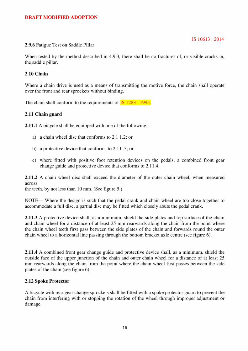
2.11.2 A chain wheel disc shall exceed the diameter of the outer chain wheel, when measured
across
the teeth, by not less than 10 mm. (See figure 5.)
NOTE— Where the design is such that the pedal crank and chain wheel are too close together to
accommodate a full disc, a partial disc may be fitted which closely abuts the pedal crank.
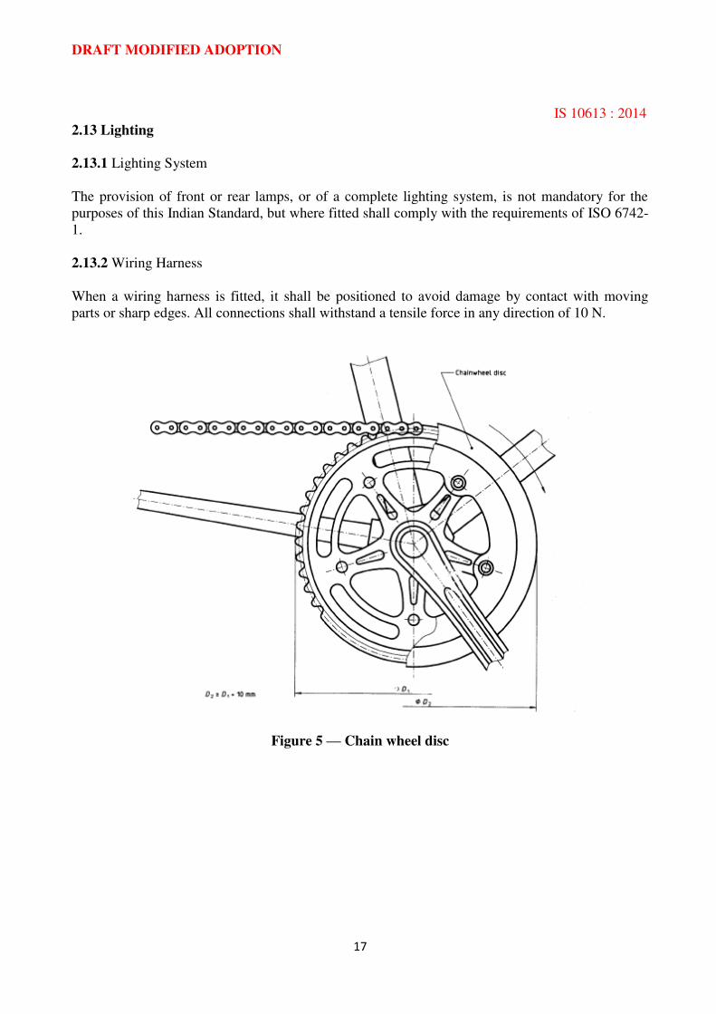
2.11.3 A protective device shall, as a minimum, shield the side plates and top surface of the chain
and chain wheel for a distance of at least 25 mm rearwards along the chain from the point where
the chain wheel teeth first pass between the side plates of the chain and forwards round the outer
chain wheel to a horizontal line passing through the bottom bracket axle centre (see figure 6).
2.11.4 A combined front gear change guide and protective device shall, as a minimum, shield the
outside face of the upper junction of the chain and outer chain wheel for a distance of at least 25
mm rearwards along the chain from the point where the chain wheel first passes between the side
plates of the chain (see figure 6).
2.12 Spoke Protector
A bicycle with rear gear change sprockets shall be fitted with a spoke protector guard to prevent the
chain from interfering with or stopping the rotation of the wheel through improper adjustment or
damage.
DRAFT MODIFIED ADOPTION
IS 10613 : 2014
17
2.13 Lighting
2.13.1 Lighting System
The provision of front or rear lamps, or of a complete lighting system, is not mandatory for the
purposes of this Indian Standard, but where fitted shall comply with the requirements of ISO 6742-
1.
2.13.2 Wiring Harness
When a wiring harness is fitted, it shall be positioned to avoid damage by contact with moving
parts or sharp edges. All connections shall withstand a tensile force in any direction of 10 N.
Figure 5 — Chain wheel disc
DRAFT MODIFIED ADOPTION
IS 10613 : 2014
18
Figure 6 — Chain and chain wheel junction
2.14 Reflectors
2.14.1 Rear Reflectors
A bicycle equipped with a rear light in accordance with 2.13 shall be additionally equipped with a
rear wide-angle reflector, or conventional reflector, meeting the requirements of IS/ISO 6742-2. A
bicycle that has no such rear light shall be equipped with a wide-angle reflector. Rear reflectors
shall be red in colour.
2.14.2 Side Reflectors
A bicycle shall be equipped with two side reflectors each visible from both sides. The reflectors
shall be either
a) wide-angle reflectors fitted on the front half and on the rear half of the bicycle. At least one
of these shall be mounted on the spokes of the wheel. Where a bicycle incorporates features
at the rear wheel other than the frame and mudguard stays, the moving reflector shall be
mounted on the front wheel; or
b) a continuous circle of reflective material applied to both sides of each wheel within 10 cm
of the outer diameter of the tyre.
Wide-angle reflectors shall comply with the requirements of IS/ISO 6742-2. Reflective materials
shall comply with the photometric requirements of IS/ISO 6742-2.
All side reflectors shall be of the same colour, either white (clear) or yellow.
2.14.3 Front Reflectors
A bicycle shall be equipped with a front wide-angle reflector complying with the requirements of
IS/ISO 6742-2. Front reflectors shall be white (clear) in colour.
DRAFT MODIFIED ADOPTION
IS 10613 : 2014
19
2.14.4 Pedal Reflectors
Each pedal shall have reflectors complying with the requirements of IS/ISO 6742-2, located on the
front and rear surfaces of the pedal. The reflector elements shall be either integral with the
construction of the pedal or mechanically attached, but shall be sufficiently recessed from the edge
of the pedal, or of the reflector housing, to prevent contact of the reflector element with a flat
surface placed in contact with the edge of the pedal. Pedal reflectors shall be yellow in colour.
2.15 Retro-Reflective Tapes
2.15.1 A bicycle shall also be equipped with retro-reflective tapes. Retro-Reflective tapes used on
bicycles shall comply with the requirements of IS 14221: 1995.
2.15.2 The details regarding placement, colour and sizes of such tapes used on bicycles shall be as
per the details given in Annex D.’
2.16 Warning Device
Where a bell or other suitable audible warning device is fitted, it shall comply with ISO 7636.
2.17 Instructions
Each bicycle shall be provided with a set of instructions containing information on:
a) preparation for riding — how to measure and adjust the seat height and handlebar height to
suit the rider, with an explanation of the warning marks on the seat pillar and handlebar
stem;
b) recommended tightening of fasteners related to handlebar, handlebar stem, saddle and
pillar, and wheels;
c) the method for determining the correct adjustment of wheel quick release mechanisms,
such as, “ the mechanism should emboss the fork ends when closed to the locked position”;
d) lubrication — where and how often to lubricate, and recommended lubricant;
e) the correct chain tension and how to adjust this;
f) adjustment of brakes and recommendations for replacement of brake blocks;
g) adjustment of gears
h) appropriate spares, i.e. tyres, tubes, brake-block holder assembly;
i) accessories — where these are offered as fitted, details should be included such as
operation, maintenance required (if any) and relevant spares (i.e. light-bulbs);
DRAFT MODIFIED ADOPTION
IS 10613 : 2014
20
j) safe riding — regular checks on brakes, tyres, steering and lighting; caution concerning
increased braking distance in wet weather;
k) the type of use for which the bicycle is designed (e.g. on-road or all-terrain) ‘with a warning against the hazards of incorrect use;
l) the correct assembly of any parts supplied unassembled.
NOTE— Any other relevant information may be included at the discretion of the manufacturer
2.18 BIS Certification Marking
2.18.1 The material may also be marked with Standard Mark.
2.18.2 The use of the Standard Mark is governed by the provisions of the Bureau of Indian
Standards Act, 1986 and the Rules and Regulations made there under. The details of conditions
under which the license for the use of Standard Mark may be granted to manufacturers or
producers may be obtained from the Bureau of Indian Standards.’
DRAFT MODIFIED ADOPTION
IS 10613 : 2014
21
SECTION 3: REQUIREMENTS OF COMPLETE BICYCLE
3.1 Road Test
When tested by the method described in 4.10, there shall be no system or component failure and no
loosening or misalignment of the seat, handlebars, control or reflectors.
The bicycle shall exhibit stable handling in turning and steering, and it shall be possible to ride
with one hand removed from the handlebar (as when giving hand signals), without difficulty of
operation or hazard to the rider.
DRAFT MODIFIED ADOPTION
IS 10613 : 2014
22
SECTION 4 TEST METHODS
4.1 Brake Block Test
The test shall be conducted on a fully assembled bicycle with the brakes adjusted to a correct
position with a rider or equivalent mass on the saddle. The combined mass of bicycle and rider (or
equivalent mass) shall be 100 kg +/- 1 %. Each brake lever shali be actuated with a force of 180 N
or a force sufficient to bring the brake lever into contact with handlebar grip, whichever is the less.
Such force shall be maintained throughout the test.
The bicycle shall then be subjected to five forward and five rearwards movements, each of which is
not less than 75 mm distance.
4.2 Brake System Load Test
4.2.1 Hand-Operated Brake
This test shall be conducted on a fully assembled bicycle. After it has been ensured that the braking
system is correctly adjusted, a force shall be applied to the brake lever or the extension lever at a
point 25 mm from the end of either type of lever, as shown in figure 7. This force shall be 450 N,
or such lesser force as is required to bring:
a) a cable-brake lever into contact with the handlebar grip, or with the handlebar in the
absence of a grip;
b) a cable-brake extension lever level with the upper surface of the handlebars or in contact
with the handlebars;
c) a rod-operated brake lever level with the upper surface of the handlebar grip.
This test shall be repeated for a total of 10 times on each hand-brake lever and on each extension
lever.
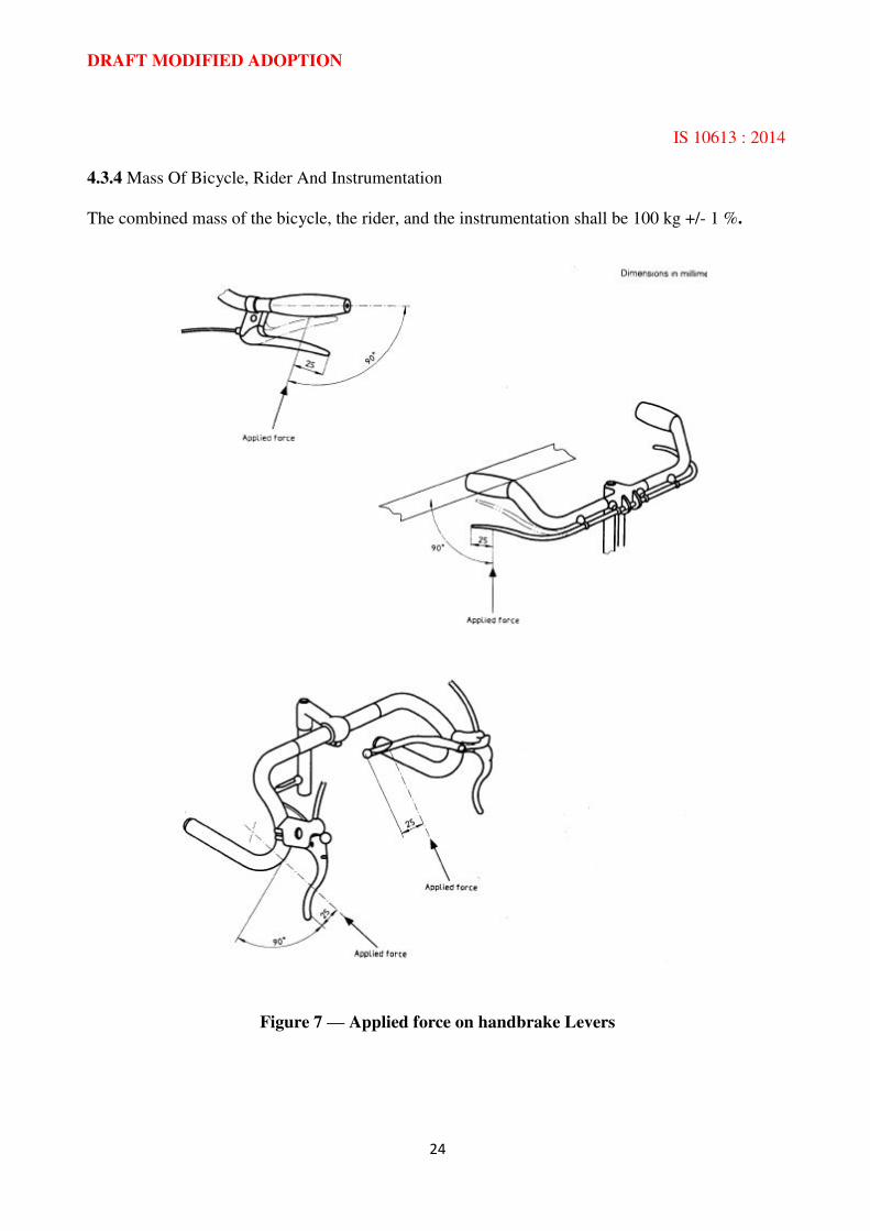
4.2.2 Back-Pedal Brake
This test shall be conducted on a fully assembled bicycle. After it has been ensured that the braking
system is correctly adjusted, and with the pedal cranks in a horizontal position, as shown in figure
8, a force shall be applied to the centre of the left-hand pedal axle. This force shall be 1500 N,
gradually applied, in a vertical direction, and shall be maintained fully for 15 s.
This test shall be repeated for a total of 10 times.
4.3 Braking Performance Test
Unless otherwise stated, these requirements apply to both dry and wet test conditions.
DRAFT MODIFIED ADOPTION
IS 10613 : 2014
23
4.3.1 Test Bicycle
The braking performance test shall be conducted on a fully assembled bicycle after the brakes have
been subjected to the load test detailed in 4.2. The brakes may be re-adjusted to a correct position if
necessary and the tyres shall be inflated to the maximum recommended pressure, as marked on the
tyre. (See 2.7.1)
4.3.2 Test Track
4.3.2.1 An indoor test track shall be used if possible. Where an outdoor track is used, special
attention should be paid to ambient conditions throughout the tests.
4.3.2.2 The gradient of the track shall not exceed 0,5’? 4.. If the gradient is less than 0,27., all runs shall be carried out in the same direction. If the gradient lies between 0,2% and 0,5?40, alternate
runs shall be carried out in opposite directions.
4.3.2.3 The surface shall be hard, of concrete or fine asphalt, free from loose dirt or gravel. The
minimum coefficient of friction between the dry surface and the bicycle tyre shall be 0,5.
.
4.3.2.4 The track shall be essentially dry at the commencement of tests. When testing to the
requirements of 2.2.5.1, the track shall remain dry throughout the tests.
4.3.2.5 The wind speed on the track shall not exceed 3 m/s during the tests.
4.3.3 Instrumentation
The test bicycle shall be instrumented to include the following.
4.3.3.1 Calibrated speedometer or tachometer, accurate to within +/- 5 % to indicate to the rider the
approximate speed at the commencement of braking.
4.3.3.2 Velocity recording device, accurate to +/- 2 % to record the velocity at the commencement
of braking.
4.3.3.3 Distance recording system, accurate to +/- 1 % to record the braking distance.
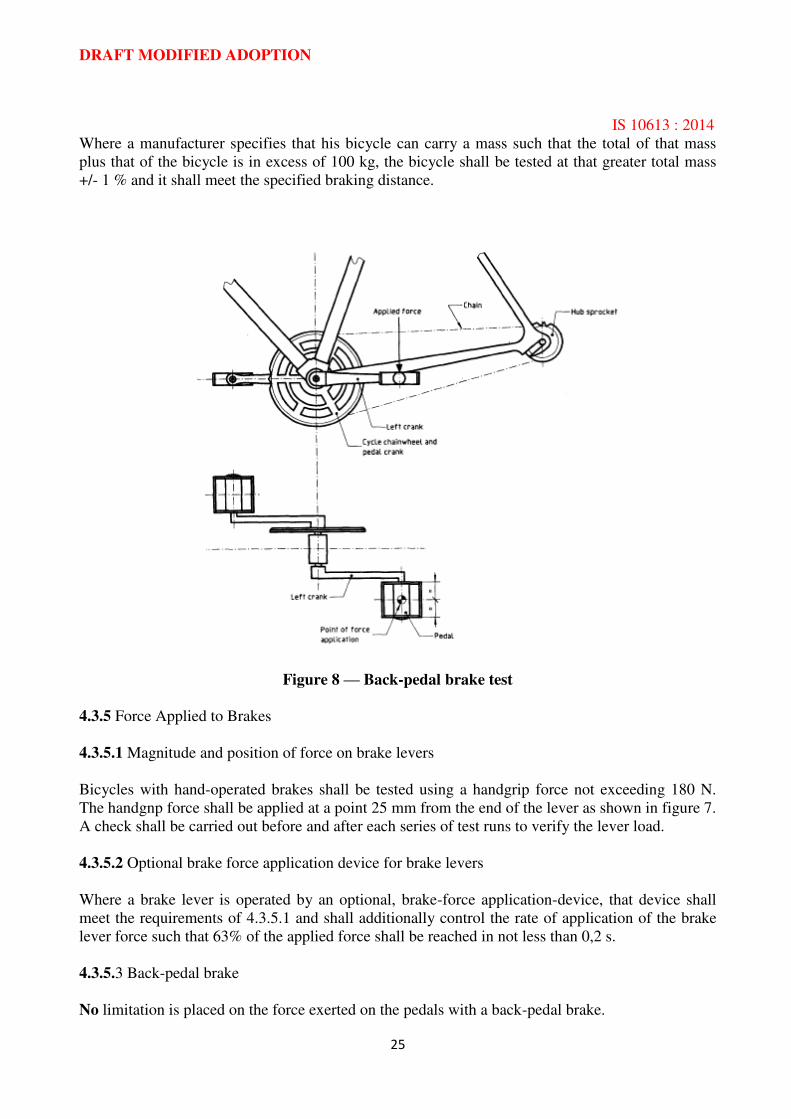
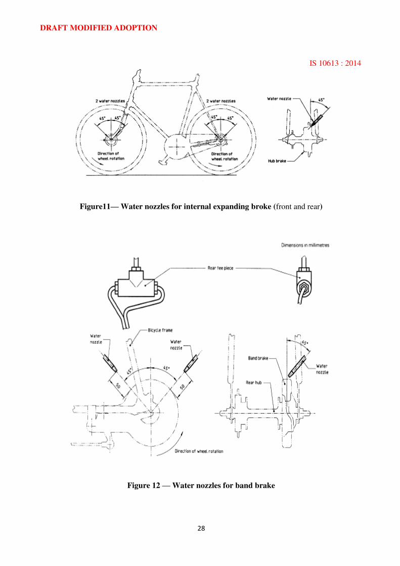
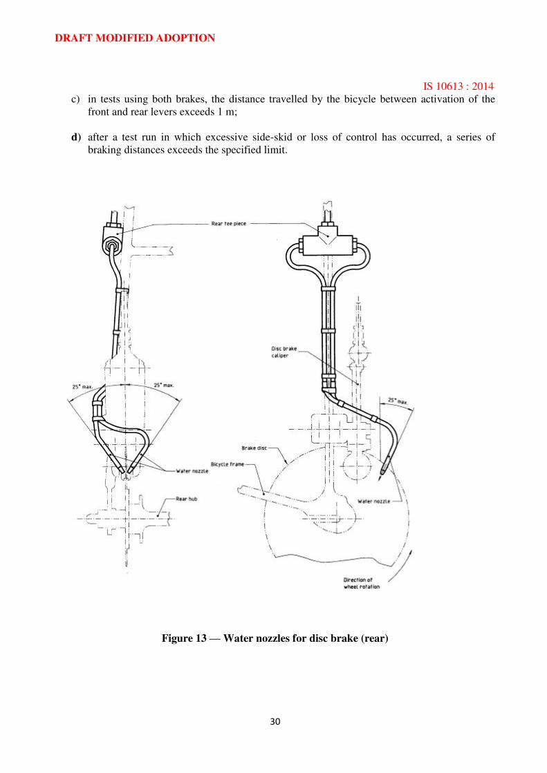
4.3.3.4 Water spray system, to provide wetting of the braking surfaces, consisting of a water
reservoir connected by tubing to a pair of nozzles on the front wheel and a pair of nozzles on the
rear wheel. A quick-acting on/off valve shall be included for control by the rider. Each nozzle shall
provide a flow of water of not less than 4 ml/s. Distilled water at ambient temperature shall be
used.
Details of the positions and directions of nozzles for caliper, internal expander, band, disc and
back-pedal brakes are given in figures 9 to 14.
4.3.3.5 Brake actuation indicating system, to record independently when each brake is actuated
DRAFT MODIFIED ADOPTION
IS 10613 : 2014
24
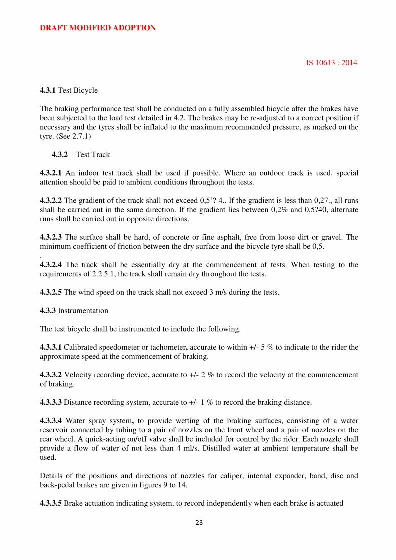
4.3.4 Mass Of Bicycle, Rider And Instrumentation
The combined mass of the bicycle, the rider, and the instrumentation shall be 100 kg +/- 1 %.
Figure 7 — Applied force on handbrake Levers
DRAFT MODIFIED ADOPTION
IS 10613 : 2014
25
Where a manufacturer specifies that his bicycle can carry a mass such that the total of that mass
plus that of the bicycle is in excess of 100 kg, the bicycle shall be tested at that greater total mass
+/- 1 % and it shall meet the specified braking distance.
Figure 8 — Back-pedal brake test
4.3.5 Force Applied to Brakes
4.3.5.1 Magnitude and position of force on brake levers
Bicycles with hand-operated brakes shall be tested using a handgrip force not exceeding 180 N.
The handgnp force shall be applied at a point 25 mm from the end of the lever as shown in figure 7.
A check shall be carried out before and after each series of test runs to verify the lever load.
4.3.5.2 Optional brake force application device for brake levers
Where a brake lever is operated by an optional, brake-force application-device, that device shall
meet the requirements of 4.3.5.1 and shall additionally control the rate of application of the brake
lever force such that 63% of the applied force shall be reached in not less than 0,2 s.
4.3.5.3 Back-pedal brake
No limitation is placed on the force exerted on the pedals with a back-pedal brake.
DRAFT MODIFIED ADOPTION
IS 10613 : 2014
26
4.3.6 Method
4.3.6.1 Test runs under dry conditions
The rider shall pedal the test bicycle until the specified test velocity apply the brakes. The bicycle
shall be brought to a smooth, safe stop. is attained. He shall stop pedalling and then apply the
brakes. The bicycle shall be brought to a smooth, safe stop.
Figure 9 — Water nozzles for caliper brake (front)
4.3.6.2 Test runs under wet conditions
The method shall be as given in 4.3.6.1, with the addition that the wetting of the brake system(s)
shall commence not less than 25 m prior to the commencement of braking (1.3.7) and shall
continue until the bicycle comes to rest.
NOTE— Excessive amounts of water maybe swept from the test track surface between runs,
4.3.6.3 Number of valid test runs
4.3.6.3.1 If the gradient of the track is less than 0,2 9!. the following runs shall be made:
a) five consecutive valid runs under dry conditions;
b) two acclimatization runs under wet conditions (results not recorded);
c) five consecutive valid runs under wet conditions
4.3.6.3.2 If the gradient of the track lies between 0,2 % and 0,5 ‘Yo, the following runs shall be
made:

DRAFT MODIFIED ADOPTION
IS 10613 : 2014
27
a) six consecutive valid runs under dry conditions with alternate runs in opposite directions;
b) two acclimatization runs under wet conditions (results not recorded);
c) six consecutive valid runs under wet conditions with alternate runs in opposite directions.
NOTE— A rest period not exceeding 3 min may be taken between successive runs.
Figure 10 — Water nozzles for caliper brake (rear)
DRAFT MODIFIED ADOPTION
IS 10613 : 2014
28
Figure11— Water nozzles for internal expanding broke (front and rear)
Figure 12 — Water nozzles for band brake
DRAFT MODIFIED ADOPTION
IS 10613 : 2014
29
4.3.7 Velocity/Distance Correction Factor
A correction factor shall be applied to the measured braking distance if the velocity as checked by
the timing device is not precisely that specified in 2.2.5.
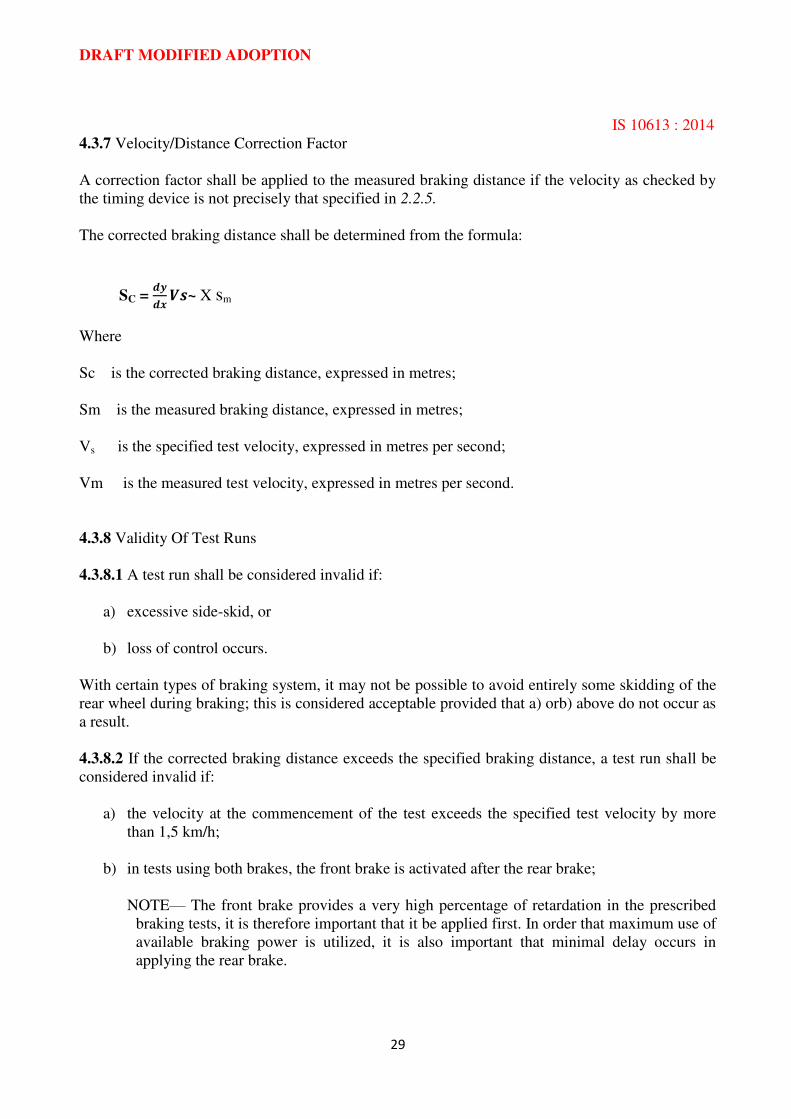
The corrected braking distance shall be determined from the formula:
SC = ~ X sm
Where
Sc is the corrected braking distance, expressed in metres;
Sm is the measured braking distance, expressed in metres;
Vs is the specified test velocity, expressed in metres per second;
Vm is the measured test velocity, expressed in metres per second.
4.3.8 Validity Of Test Runs
4.3.8.1 A test run shall be considered invalid if:
a) excessive side-skid, or
b) loss of control occurs.
With certain types of braking system, it may not be possible to avoid entirely some skidding of the
rear wheel during braking; this is considered acceptable provided that a) orb) above do not occur as
a result.
4.3.8.2 If the corrected braking distance exceeds the specified braking distance, a test run shall be
considered invalid if:
a) the velocity at the commencement of the test exceeds the specified test velocity by more
than 1,5 km/h;
b) in tests using both brakes, the front brake is activated after the rear brake;
NOTE— The front brake provides a very high percentage of retardation in the prescribed
braking tests, it is therefore important that it be applied first. In order that maximum use of
available braking power is utilized, it is also important that minimal delay occurs in
applying the rear brake.
DRAFT MODIFIED ADOPTION
IS 10613 : 2014
30
c) in tests using both brakes, the distance travelled by the bicycle between activation of the
front and rear levers exceeds 1 m;
d) after a test run in which excessive side-skid or loss of control has occurred, a series of
braking distances exceeds the specified limit.
Figure 13 — Water nozzles for disc brake (rear)

DRAFT MODIFIED ADOPTION
IS 10613 : 2014
31
Figure 14 — Water nozzles for back-pedal brake
4.3.8.3 If the corrected braking distance is less than the specified braking distance, a test run shall
be considered invalid if:
a) the velocity at the commencement of braking is more than 1,5 km/h below the specified test
velocity;
b) in tests using both brakes, the distance travelled by the bicycle between confirmation of the
velocity and activation of the rear levers exceeds 2 m.
If the corrected braking distance exceeds the braking distance specified in table 1, the test run shall
be considered valid.
4.3.9 Test Results
4.3.9.1 Braking under dry conditions
Depending on the gradient of the test track, the test result shall be the average value of the
corrected braking distances (see 4.3.7) of the tests runs of either 4.3.6.3.1 a) or 4.3.6.3.2 a).
For compliance with the requirements of 2.2.5.1, the above average values shall not exceed the
relevant braking distances specified in table 1.
DRAFT MODIFIED ADOPTION
IS 10613 : 2014
32
4.3.9.2 Braking under wet conditions
Depending on the gradient of the test track, the test result shall be the average value of the
corrected braking distances (see 4.3.7) of the test runs of either 4.3.6.3.1 c) or 4.3.6.3.2 c).
For compliance with the requirements of 2.2.5.2, the above average values shall not exceed the
relevant braking distances specified in table 1.
4.4 Back-Pedal Brake Linearity Test
This test shall be conducted on a fully assembled bicycle. The output force for a back-pedal brake
shall be measured tangentially to the circumference of the rear tyre, when the wheel is rotated in
the direction of forward movement, whilst a force of between 90 N and 300 N is being applied to
the pedal at right angles to the crank and in the direction of braking.
The braking force reading shall be taken during a steady pull and after one revolution of the wheel.
A minimum of five results, each at a different pedal force level, shall be taken. Each result shall be
the average of three individual readings at the same load level.
The results shall be plotted on a graph, showing the line of best fit and the A 20 % limit lines
obtained by the method of least squares outlined in annex A.
4.5 Steering Assembly Test
4.5.l Handlebar Stem
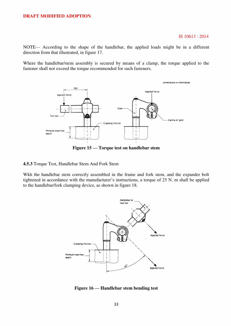
4.5.1.1 Torque test
With the handlebar stem securely clamped in a fixture to the minimum insertion depth (see 2.3.2),
and a test bar or handlebar assembled securely to the stem, a torque of 108 N. m shall be applied to
the stem by means of the test bar in a plane parallel to the stem and in the direction shown in figure
15.
4.5.1.2 Handlebar stem bending test
With the handlebar stem securely clamped in a fixture to the minimum insertion depth (see 2.3.2), a
force shall be applied through the handlebar attachment point in a forward direction and at 45° to
the axis of the stem shank as shown in figure 16.
If the stem yields, it shall be capable of being bent through an angle up to 45° from the stem axis
without fracture and shall support a force of not less than 1600 N.
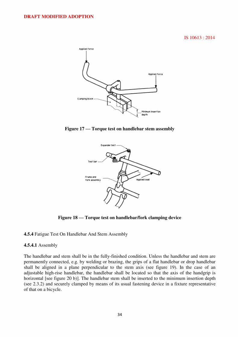
4.5.2 Torque Test, Handlebar and Stem
With the stem of the handlebar assembly securely clamped to the minimum insertion depth in a
fixture, a force of 220 N shall be applied simultaneously to each side of the handlebar in a direction
and at the location that will provide a maximum turning moment at the junction of the handlebar
and stem. Where this location occurs at the end of the handlebar, the force shall be applied as near
to the end as is practicable, and in any case not further than 15 mm from the end. (See figure 17.)
DRAFT MODIFIED ADOPTION
IS 10613 : 2014
33
NOTE— According to the shape of the handlebar, the applied loads might be in a different
direction from that illustrated, in figure 17.
Where the handlebar/stem assembly is secured by means of a clamp, the torque applied to the
fastener shall not exceed the torque recommended for such fasteners.
Figure 15 — Torque test on handlebar stem
4.5.3 Torque Test, Handlebar Stem And Fork Stem
Wkh the handlebar stem correctly assembled in the frame and fork stem, and the expander bolt
tightened in accordance with the manufacturer’s instructions, a torque of 25 N. m shall be applied to the handlebar/fork clamping device, as shown in figure 18.
Figure 16 — Handlebar stem bending test
DRAFT MODIFIED ADOPTION
IS 10613 : 2014
34
Figure 17 — Torque test on handlebar stem assembly
Figure 18 — Torque test on handlebar/fork clamping device
4.5.4 Fatigue Test On Handlebar And Stem Assembly
4.5.4.1 Assembly
The handlebar and stem shall be in the fully-finished condition. Unless the handlebar and stem are
permanently connected, e.g. by welding or brazing, the grips of a flat handlebar or drop handlebar
shall be aligned in a plane perpendicular to the stem axis (see figure 19). In the case of an
adjustable high-rise handlebar, the handlebar shall be located so that the axis of the handgrip is
horizontal [see figure 20 b)]. The handlebar stem shall be inserted to the minimum insertion depth
(see 2.3.2) and securely clamped by means of its usual fastening device in a fixture representative
of that on a bicycle.
DRAFT MODIFIED ADOPTION
IS 10613 : 2014
35
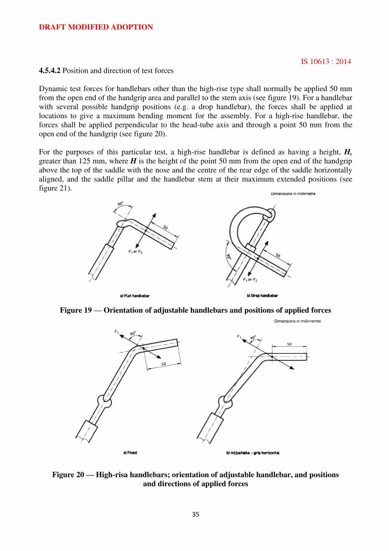
4.5.4.2 Position and direction of test forces
Dynamic test forces for handlebars other than the high-rise type shall normally be applied 50 mm
from the open end of the handgrip area and parallel to the stem axis (see figure 19). For a handlebar
with several possible handgrip positions (e.g. a drop handlebar), the forces shall be applied at
locations to give a maximum bending moment for the assembly. For a high-rise handlebar, the
forces shall be applied perpendicular to the head-tube axis and through a point 50 mm from the
open end of the handgrip (see figure 20).
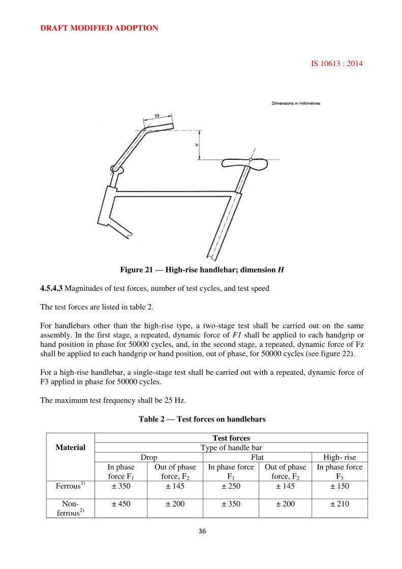
For the purposes of this particular test, a high-rise handlebar is defined as having a height, H,
greater than 125 mm, where H is the height of the point 50 mm from the open end of the handgrip
above the top of the saddle with the nose and the centre of the rear edge of the saddle horizontally
aligned, and the saddle pillar and the handlebar stem at their maximum extended positions (see
figure 21).
Figure 19 — Orientation of adjustable handlebars and positions of applied forces
Figure 20 — High-risa handlebars; orientation of adjustable handlebar, and positions
and directions of applied forces
DRAFT MODIFIED ADOPTION
IS 10613 : 2014
36
Figure 21 — High-rise handlebar; dimension H
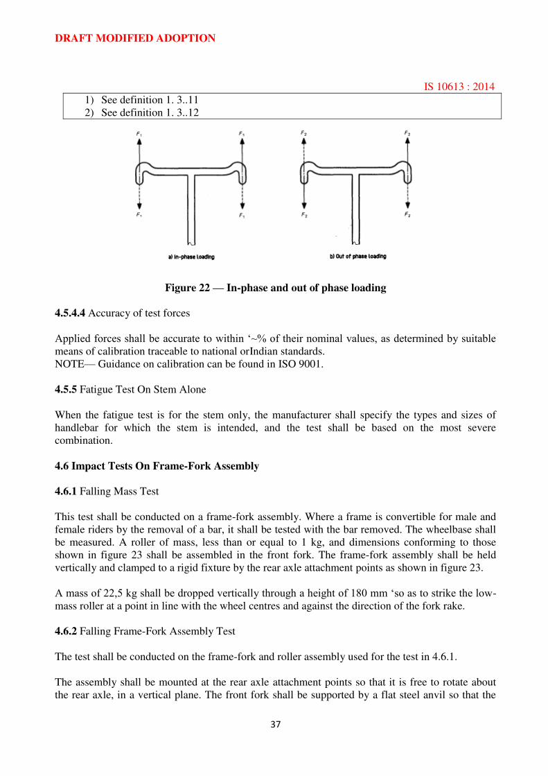
4.5.4.3 Magnitudes of test forces, number of test cycles, and test speed
The test forces are listed in table 2.
For handlebars other than the high-rise type, a two-stage test shall be carried out on the same
assembly. In the first stage, a repeated, dynamic force of F1 shall be applied to each handgrip or
hand position in phase for 50000 cycles, and, in the second stage, a repeated, dynamic force of Fz
shall be applied to each handgrip or hand position, out of phase, for 50000 cycles (see figure 22).
For a high-rise handlebar, a single-stage test shall be carried out with a repeated, dynamic force of
F3 applied in phase for 50000 cycles.
The maximum test frequency shall be 25 Hz.
Table 2 — Test forces on handlebars
Material
Test forces
Type of handle bar
Drop Flat High- rise
In phase
force F1
Out of phase
force, F2
In phase force
F1
Out of phase
force, F2
In phase force
F3
Ferrous1)
± 350 ± 145 ± 250 ± 145 ± 150
Non-
ferrous2)
± 450 ± 200 ± 350 ± 200 ± 210
DRAFT MODIFIED ADOPTION
IS 10613 : 2014
37
1) See definition 1. 3..11
2) See definition 1. 3..12
Figure 22 — In-phase and out of phase loading
4.5.4.4 Accuracy of test forces
Applied forces shall be accurate to within ‘~% of their nominal values, as determined by suitable means of calibration traceable to national orIndian standards.
NOTE— Guidance on calibration can be found in ISO 9001.
4.5.5 Fatigue Test On Stem Alone
When the fatigue test is for the stem only, the manufacturer shall specify the types and sizes of
handlebar for which the stem is intended, and the test shall be based on the most severe
combination.
4.6 Impact Tests On Frame-Fork Assembly
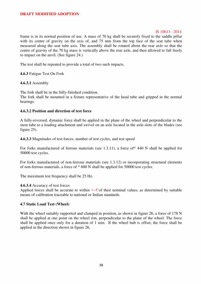
4.6.1 Falling Mass Test
This test shall be conducted on a frame-fork assembly. Where a frame is convertible for male and
female riders by the removal of a bar, it shall be tested with the bar removed. The wheelbase shall
be measured. A roller of mass, less than or equal to 1 kg, and dimensions conforming to those
shown in figure 23 shall be assembled in the front fork. The frame-fork assembly shall be held
vertically and clamped to a rigid fixture by the rear axle attachment points as shown in figure 23.
A mass of 22,5 kg shall be dropped vertically through a height of 180 mm ‘so as to strike the low-
mass roller at a point in line with the wheel centres and against the direction of the fork rake.
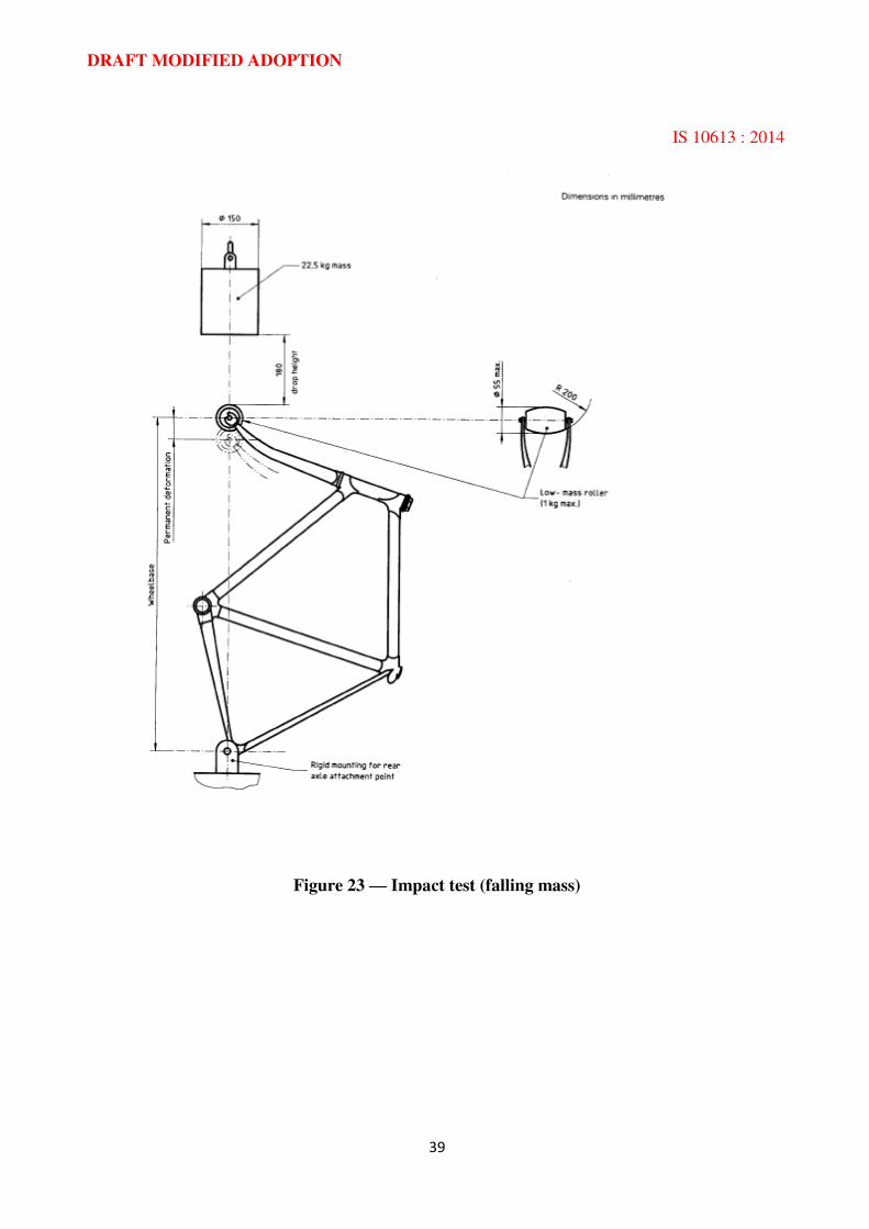
4.6.2 Falling Frame-Fork Assembly Test
The test shall be conducted on the frame-fork and roller assembly used for the test in 4.6.1.
The assembly shall be mounted at the rear axle attachment points so that it is free to rotate about
the rear axle, in a vertical plane. The front fork shall be supported by a flat steel anvil so that the
DRAFT MODIFIED ADOPTION
IS 10613 : 2014
38
frame is in its normal position of use. A mass of 70 kg shall be securely fixed to the saddle pillar
with its centre of gravity on the axis of, and 75 mm from the top face of the seat tube when
measured along the seat tube axis. The assembly shall be rotated about the rear axle so that the
centre of gravity of the 70 kg mass is vertically above the rear axle, and then allowed to fall freely
to impact on the anvil. (See figure 24.)
The test shall be repeated to provide a total of two such impacts.
4.6.3 Fatigue Test On Fork
4.6.3.1 Assembly
The fork shall be in the fully-finished condition.
The fork shall be mounted in a fixture representative of the head tube and gripped in the normal
bearings.
4.6.3.2 Position and direction of test force
A fully-reversed, dynamic force shall be applied in the plane of the wheel and perpendicular to the
stem tube to a loading attachment and swivel on an axle located in the axle-slots of the blades (see
figure 25).
4.6.3.3 Magnitudes of test forces, number of test cycles, and test speed
For forks manufactured of ferrous materials (see 1.3.11), a force of* 440 N shall be applied for
50000 test cycles.
For forks manufactured of non-ferrous materials (see 1.3.12) or incorporating structural elements
of non-ferrous materials, a force of * 600 N shall be applied for 50000 test cycles.
The maximum test frequency shall be 25 Hz.
4.6.3.4 Accuracy of test forces
Applied forces shall be accurate to within +~5‘of their nominal values, as determined by suitable
means of calibration traceable to national or Indian standards.
4.7 Static Load Test (Wheel)
With the wheel suitably supported and clamped in position, as shown in figure 26, a force of 178 N
shall be applied at one point on the wheel rim, perpendicular to the plane of the wheel. The force
shall be applied once only for a duration of 1 min. If the wheel hub is offset, the force shall be
applied in the direction shown in figure 26,
DRAFT MODIFIED ADOPTION
IS 10613 : 2014
39
Figure 23 — Impact test (falling mass)
DRAFT MODIFIED ADOPTION
IS 10613 : 2014
40
Figure 24 — Impact test (falling frame-fork assembly)
Figure 25 — Typical test arrangement for a fork
Figure 26 — Static load test on wheel

DRAFT MODIFIED ADOPTION
IS 10613 : 2014
41
4.8 Pedal Tests
4.8.1 Drive system static load test
The test shall be conducted on an assembly comprising frame, pedals, transmission system, rear
wheel assembly and, where appropriate, the gear change mechanism. The frame shall be supported
with its longitudinal plane vertical, and with the rear wheel clamped securely at the rim to prevent
the wheel rotating.
4.8.1.1 Single speed system
4.8.1.1.1 With the left-hand crank in the forward horizontal position, a force of 1500 N shall be
gradually applied vertically downwards to the centre of the left-hand pedal.
The force shall be maintained for 15s.
Should the system yield or the drive sprockets tighten such that the crank rotates while under load
to a position more than 30° below horizontal, the crank shall be returned to horizontal, or to some
appropriate position above horizontal to take account of system yield, and the test repeated.
4.8.1.1.2 On completion of the test in 4.8.1.1.1, the test shall be repeated with the right-hand crank
in the forward horizontal position and the load applied to the centre of the right-hand pedal.
4.8.1.2 Multispeed system
4.8.1.2.1 The test given in 4.8.1 .1.1 shall be conducted with the transmission correctly adjusted in
its highest gear.
4.8.1.2.2 The test given in 4.8.1 .1.2 shall be conducted with the transmission correctly adjusted in
its lowest gear.
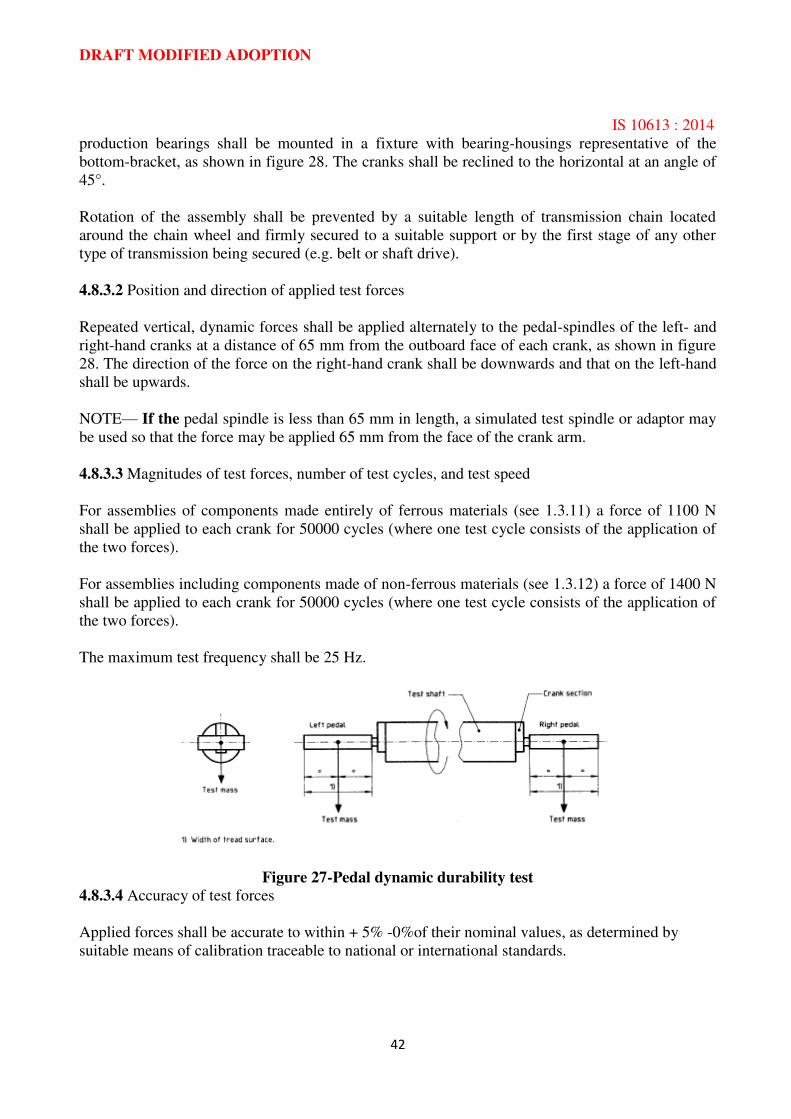
4.8.2 Pedal dynamic durability test
With suitable sections cut from a pair of cranks fitted securely to a test shaft, assemble a pair of
pedals to the crank sections. A mass totalling 50 kg shall be suspended from each pedal by means
of a spring to minimize oscillation of the load, as shown in figure 27. The shaft shall then be driven
at approximately 100 min-l for a total of 1000000 revolutions. After 500000 revolutions, the pedals
shall be turned through 180° if they are provided with two treads.
4.8.3 Fatigue Test On Crank Assembly
4.8.3.1 Assembly
All of the components under test shall be in the fully-finished condition. The two pedal spindles,
the two cranks, the chain wheel (or other drive component), and the bottom-bracket spindle located
on its normal-
DRAFT MODIFIED ADOPTION
IS 10613 : 2014
42
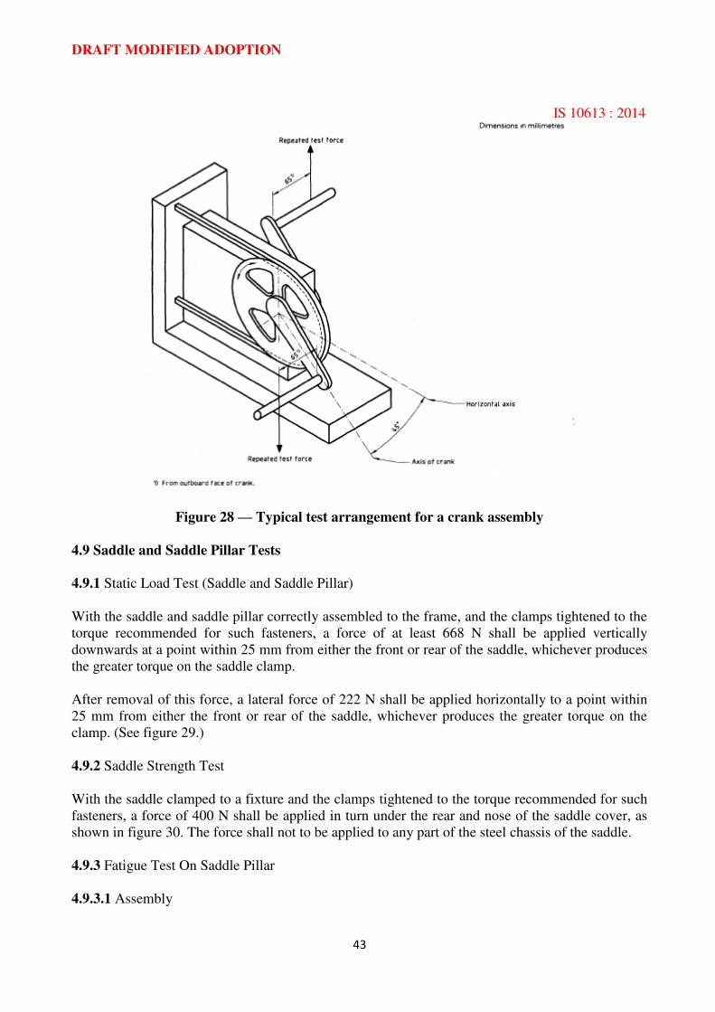
production bearings shall be mounted in a fixture with bearing-housings representative of the
bottom-bracket, as shown in figure 28. The cranks shall be reclined to the horizontal at an angle of
45°.
Rotation of the assembly shall be prevented by a suitable length of transmission chain located
around the chain wheel and firmly secured to a suitable support or by the first stage of any other
type of transmission being secured (e.g. belt or shaft drive).
4.8.3.2 Position and direction of applied test forces
Repeated vertical, dynamic forces shall be applied alternately to the pedal-spindles of the left- and
right-hand cranks at a distance of 65 mm from the outboard face of each crank, as shown in figure
28. The direction of the force on the right-hand crank shall be downwards and that on the left-hand
shall be upwards.
NOTE— If the pedal spindle is less than 65 mm in length, a simulated test spindle or adaptor may
be used so that the force may be applied 65 mm from the face of the crank arm.
4.8.3.3 Magnitudes of test forces, number of test cycles, and test speed
For assemblies of components made entirely of ferrous materials (see 1.3.11) a force of 1100 N
shall be applied to each crank for 50000 cycles (where one test cycle consists of the application of
the two forces).
For assemblies including components made of non-ferrous materials (see 1.3.12) a force of 1400 N
shall be applied to each crank for 50000 cycles (where one test cycle consists of the application of
the two forces).
The maximum test frequency shall be 25 Hz.
Figure 27-Pedal dynamic durability test
4.8.3.4 Accuracy of test forces
Applied forces shall be accurate to within + 5% -0%of their nominal values, as determined by
suitable means of calibration traceable to national or international standards.
DRAFT MODIFIED ADOPTION
IS 10613 : 2014
43
Figure 28 — Typical test arrangement for a crank assembly
4.9 Saddle and Saddle Pillar Tests
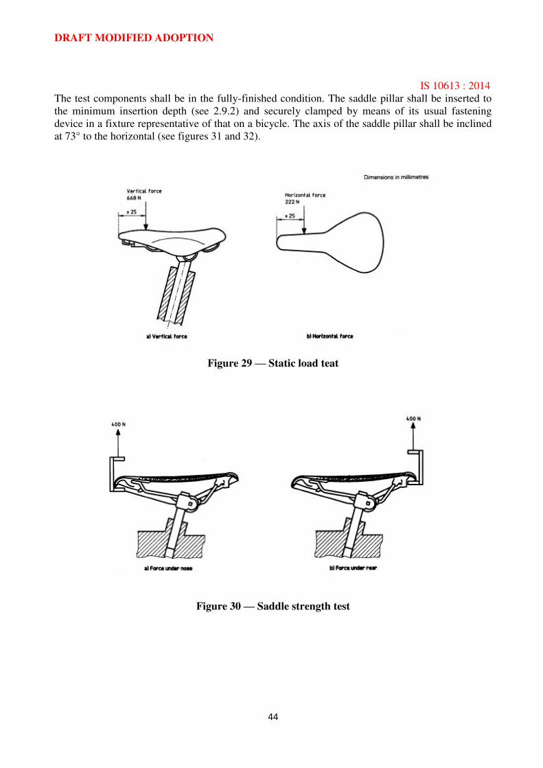
4.9.1 Static Load Test (Saddle and Saddle Pillar)
With the saddle and saddle pillar correctly assembled to the frame, and the clamps tightened to the
torque recommended for such fasteners, a force of at least 668 N shall be applied vertically
downwards at a point within 25 mm from either the front or rear of the saddle, whichever produces
the greater torque on the saddle clamp.
After removal of this force, a lateral force of 222 N shall be applied horizontally to a point within
25 mm from either the front or rear of the saddle, whichever produces the greater torque on the
clamp. (See figure 29.)
4.9.2 Saddle Strength Test
With the saddle clamped to a fixture and the clamps tightened to the torque recommended for such
fasteners, a force of 400 N shall be applied in turn under the rear and nose of the saddle cover, as
shown in figure 30. The force shall not to be applied to any part of the steel chassis of the saddle.
4.9.3 Fatigue Test On Saddle Pillar
4.9.3.1 Assembly
DRAFT MODIFIED ADOPTION
IS 10613 : 2014
44
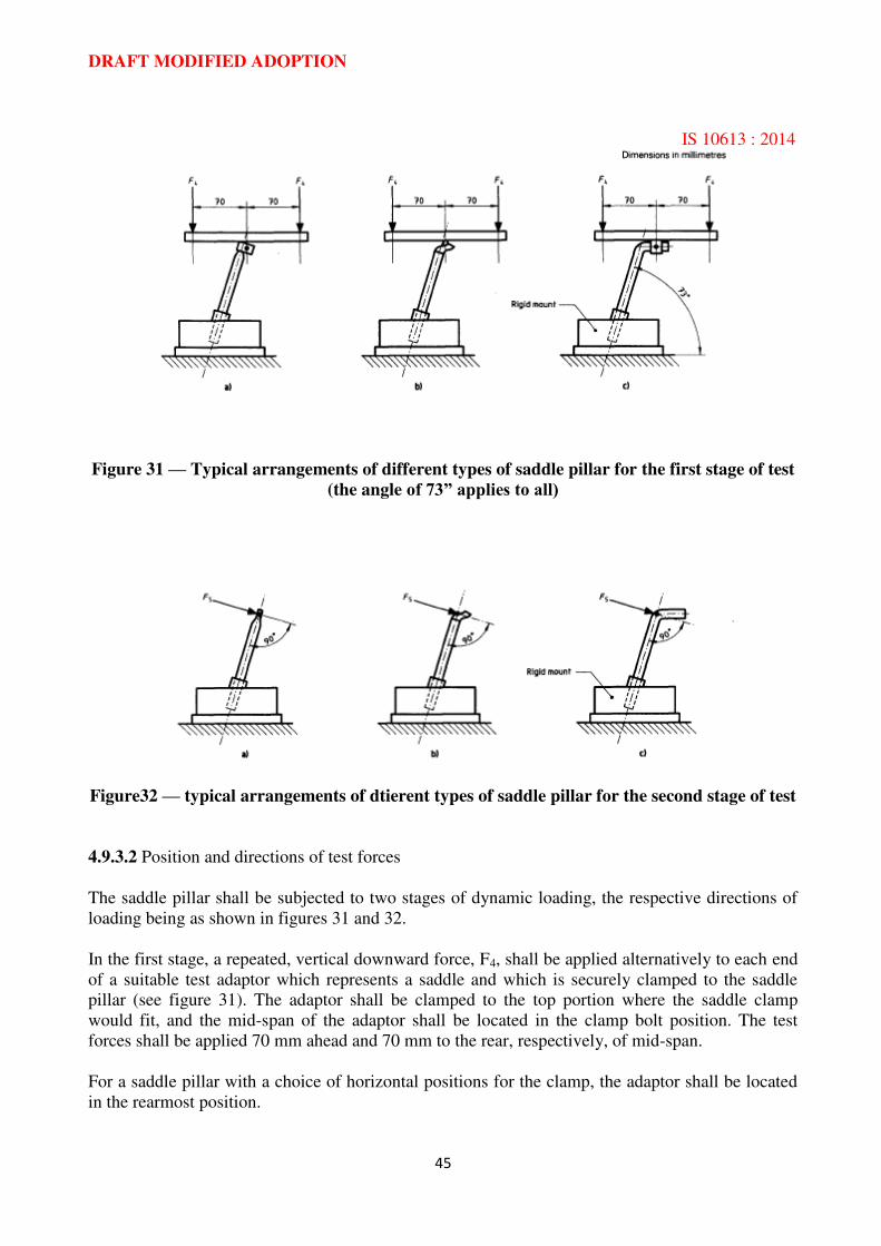
The test components shall be in the fully-finished condition. The saddle pillar shall be inserted to
the minimum insertion depth (see 2.9.2) and securely clamped by means of its usual fastening
device in a fixture representative of that on a bicycle. The axis of the saddle pillar shall be inclined
at 73° to the horizontal (see figures 31 and 32).
Figure 29 — Static load teat
Figure 30 — Saddle strength test
DRAFT MODIFIED ADOPTION
IS 10613 : 2014
45
Figure 31 — Typical arrangements of different types of saddle pillar for the first stage of test
(the angle of 73” applies to all)
Figure32 — typical arrangements of dtierent types of saddle pillar for the second stage of test
4.9.3.2 Position and directions of test forces
The saddle pillar shall be subjected to two stages of dynamic loading, the respective directions of
loading being as shown in figures 31 and 32.
In the first stage, a repeated, vertical downward force, F4, shall be applied alternatively to each end
of a suitable test adaptor which represents a saddle and which is securely clamped to the saddle
pillar (see figure 31). The adaptor shall be clamped to the top portion where the saddle clamp
would fit, and the mid-span of the adaptor shall be located in the clamp bolt position. The test
forces shall be applied 70 mm ahead and 70 mm to the rear, respectively, of mid-span.
For a saddle pillar with a choice of horizontal positions for the clamp, the adaptor shall be located
in the rearmost position.
DRAFT MODIFIED ADOPTION
IS 10613 : 2014
46
In the second stage, a repeated, rearward force, F5, shall be applied at 90° to the main axis of the
pillar. For a straight pillar, the force shall be applied through the centre of that position of the tube
intended for the saddle clamp [see figure 32 a), and for a pillar with a horizontal extension the force
shall be applied through the intersection of the axes of the main tube and the extension [see figures
32 b) and c)].
4.9.3.3 Magnitudes of test forces, number of test cycles, and test speed
The test forces are given in table 3.
In each stage, forces shall be applied for 50000 cycles where a cycle represents the application of
the two alternating forces in the first stage and the application of the single force in the second
stage.
The maximum test frequency shall be 25 Hz.
Table 3 — Test forces on saddle pillar
Material
Test force
N
F4 F5
Ferrous i) 850 650
Non-ferrous 2)
1200 900
1) See definition 1.3.11.
2) See definition 1.3.12.
4.9.3.4 Accuracy of test forces
Applied forces shall be accurate to within + 5%-0 of their nominal values, as determined by
suitable means of calibration traceable to national or Indian standards.
4.10 Road Test
Each bicycle selected for the road test shall first be checked and adjusted if necessary to ensure that
the steering and wheels rotate freely without slackness, that brakes are adjusted correctly and do
not impede wheel rotation. Wheel alignment shall be checked and corrected if necessary and tyres
inflated to the recommended pressure as marked on the sidewall of the tyre. Drive chain adjustment
shall be checked and corrected if necessary and any gear control fitted shall be checked for correct
and free operation.
The saddle and handlebar positions shall be carefully adjusted to suit the rider.
The bicycle shall be ridden for at least 1 km by a rider of appropriate size.
During the test, the bicycle shall be ridden five times over a course, 30 m in length, consisting of
wooden strips measuring 50 mm wide and 25 mm high with a 12 mm by 45° chamfer on the
corners contacting the tyres. The strips shall be spaced every 2 m over the 30 m course. The bicycle
shall be ridden over this course at speeds consistent with those indicated in 2.2.5.2.
DRAFT MODIFIED ADOPTION
IS 10613 : 2014
47
Annex A
(Informative)
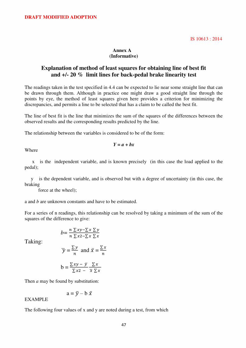
Explanation of method of least squares for obtaining line of best fit
and +/- 20 % limit lines for back-pedal brake linearity test
The readings taken in the test specified in 4.4 can be expected to lie near some straight line that can
be drawn through them. Although in practice one might draw a good straight line through the
points by eye, the method of least squares given here provides a criterion for minimizing the
discrepancies, and permits a line to be selected that has a claim to be called the best fit.
The line of best fit is the line that minimizes the sum of the squares of the differences between the
observed results and the corresponding results predicted by the line.
The relationship between the variables is considered to be of the form:
Y = a + bx
Where
x is the independent variable, and is known precisely (in this case the load applied to the
pedal);
y is the dependent variable, and is observed but with a degree of uncertainty (in this case, the
braking
force at the wheel);
a and b are unknown constants and have to be estimated.
For a series of n readings, this relationship can be resolved by taking a minimum of the sum of the
squares of the difference to give:
b= ∑ ∑ ∑ ∑ ∑ ∑
Taking:
= ∑ and =
∑
b = ∑ ∑ ∑ ∑
Then a may be found by substitution:
a = – b
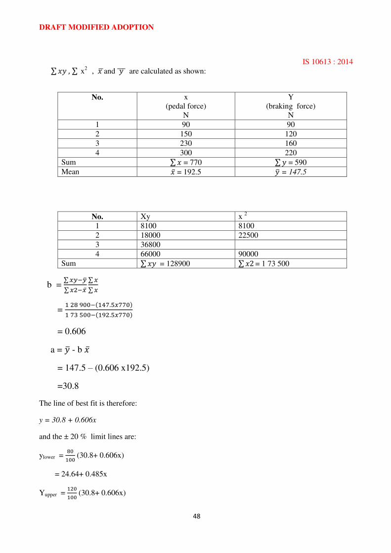
EXAMPLE
The following four values of x and y are noted during a test, from which
DRAFT MODIFIED ADOPTION
IS 10613 : 2014
48
∑ ∑ x2 , and are calculated as shown:
No. x
(pedal force)
N
Y
(braking force)
N
1 90 90
2 150 120
3 230 160
4 300 220
Sum ∑ = 770 ∑ = 590
Mean = 192.5 = 147.5
No. Xy x 2
1 8100 8100
2 18000 22500
3 36800
4 66000 90000
Sum ∑ = 128900 ∑ = 1 73 500
b = ∑ ∑ ∑ ∑
=
= 0.606
a = - b = 147.5 – (0.606 x192.5)
=30.8
The line of best fit is therefore:
y = 30.8 + 0.606x
and the ± 20 % limit lines are:
ylower = (30.8+ 0.606x)
= 24.64+ 0.485x
Yupper = (30.8+ 0.606x)
DRAFT MODIFIED ADOPTION
IS 10613 : 2014
49
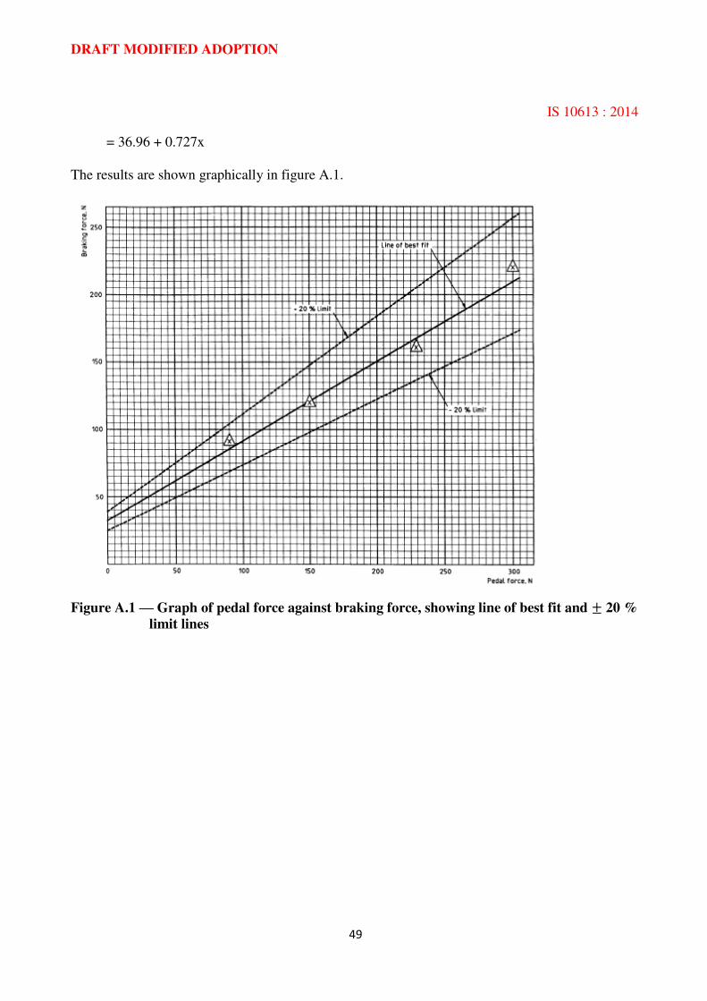
= 36.96 + 0.727x
The results are shown graphically in figure A.1.
Figure A.1 — Graph of pedal force against braking force, showing line of best fit and 20 %
limit lines

DRAFT MODIFIED ADOPTION
IS 10613 : 2014
50
Annex B (Informative)
Steering geometry
The steering geometry employed, as shown in figure B.1, will generally be dictated by the use for
which the bicycle is intended but it is nevertheless recommended that
a) the steering head angle be not more than 75° and not less than 65° in relation to the ground
line; and
b) the steering axis intersects a line perpendicular to the ground line, drawn through the wheel
centre, at a point not lower than 15% and not higher than 60’% of the wheel radius when measured from the ground line.
Figure B.1 — Steering geometry
DRAFT MODIFIED ADOPTION
IS 10613 : 2014
51
Annex C (Informative)
Bibliography
[1] ISO1lO1:1983, Technical/ drawings —Geometrical tolerance — Tolerance of form,
orientation,
location and run-out — Generalities, definitions, symbols, indications on drawings.
[2] ISO 3452:1984, Non-destructive testing — Penetrate inspection — General Principles.
[3] ISO 9001:1994, Quality systems — Model for quality assurance in design, development,
production,
installation and servicing.
DRAFT MODIFIED ADOPTION
IS 10613 : 2014
52
ANNEX D
(Clause 2.15)
D-1 REQUIREMENTS OF PLACEMENT, COLOUR AND SIZES OF RETRO-
REFLECTIVE TAPES TO BE USED FOR SAFETY OF BICYCLES
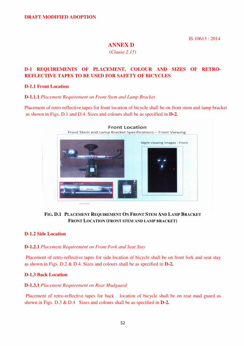
D-1.1 Front Location
D-1.1.1 Placement Requirement on Front Stem and Lamp Bracket
Placement of retro-reflective tapes for front location of bicycle shall be on front stem and lamp bracket
as shown in Figs. D.1 and D.4. Sizes and colours shall be as specified in D-2.
FIG. D.1 PLACEMENT REQUIREMENT ON FRONT STEM AND LAMP BRACKET
FRONT LOCATION (FRONT STEM AND LAMP BRACKET)
D-1.2 Side Location
D-1.2.1 Placement Requirement on Front Fork and Seat Stay
Placement of retro-reflective tapes for side location of bicycle shall be on front fork and seat stay
as shown in Figs. D.2 & D.4. Sizes and colours shall be as specified in D-2.
D-1.3 Back Location
D-1.3.1 Placement Requirement on Rear Mudguard
Placement of retro-reflective tapes for back location of bicycle shall be on rear mud guard as
shown in Figs. D.3 & D.4 Sizes and colours shall be as specified in D-2.

DRAFT MODIFIED ADOPTION
IS 10613 : 2014
53
FIG. D.2 PLACEMENT REQUIREMENT ON FRONT FORK AND SEAT STAY
SIDE LOCATION
FIG. D.3 PLACEMENT REQUIREMENT ON REAR MUDGUARD
BACK LOCATION
DRAFT MODIFIED ADOPTION
IS 10613 : 2014
54
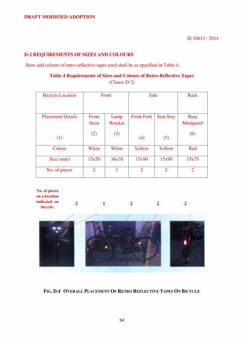
D-2 REQUIREMENTS OF SIZES AND COLOURS
Sizes and colours of retro-reflective tapes used shall be as specified in Table 4.
Table 4 Requirements of Sizes and Colours of Retro-Reflective Tapes
(Clause D-2)
Bicycle Location
Front
Side
Back
Placement Details
(1)
Front
Stem
(2)
Lamp
Bracket
(3)
Front Fork
(4)
Seat Stay
(5)
Rear
Mudguard
(6)
Colour White White Yellow Yellow Red
Size (mm) 15x50 36x70 15x90 15x90 15x75
No. of pieces 2 1 2 2 2
No. of pieces
on a location
indicated on
bicycle: 2 1 2 2 2
FIG. D.4 OVERALL PLACEMENT OF RETRO REFLECTIVE TAPES ON BICYCLE


![Accessories for FOLDING BIKES - Tern Bicycles Japan...29Kinetix Pro TT Handlebar(キネティクスプロ TT ハンドルバー) [ブラック] 440×Ø25.4mm ¥7,800(税別)](https://img.pdfslide.tips/doc/110x75/611239b74438d80c7c10d64f/accessories-for-folding-bikes-tern-bicycles-japan-29kinetix-pro-tt-handlebariffff.jpg)