Embed Size (px)
Citation preview
7/31/2019 Fault Tolerant ES Subramanian
http://slidepdf.com/reader/full/fault-tolerant-es-subramanian 1/15
Hindawi Publishing CorporationEURASIP Journal on Embedded SystemsVolume 2006, Article ID 42168, Pages 1–15DOI 10.1155/ES/2006/42168
Modeling and Design of Fault-Tolerant and Self-AdaptiveReconfigurable Networked Embedded Systems
Thilo Streichert, Dirk Koch, Christian Haubelt, and J ¨ urgen Teich
Department of Computer Science 12, University of Erlangen-Nuremberg, Am Weichselgarten 3, 91058 Erlangen, Germany
Received 15 December 2005; Accepted 13 April 2006
Automotive, avionic, or body-area networks are systems that consist of several communicating control units specialized for certain
purposes. Typically, diff erent constraints regarding fault tolerance, availability and also flexibility are imposed on these systems.In this article, we will present a novel framework for increasing fault tolerance and flexibility by solving the problem of hard-ware/software codesign online. Based on field-programmable gate arrays (FPGAs) in combination with CPUs, we allow migratingtasks implemented in hardware or software from one node to another. Moreover, if not enough hardware/software resources areavailable, the migration of functionality from hardware to software or vice versa is provided. Supporting such flexibility throughservices integrated in a distributed operating system for networked embedded systems is a substantial step towards self-adaptivesystems. Beside the formal definition of methods and concepts, we describe in detail a first implementation of a reconfigurablenetworked embedded system running automotive applications.
Copyright © 2006 Thilo Streichert et al. This is an open access article distributed under the Creative Commons AttributionLicense, which permits unrestricted use, distribution, and reproduction in any medium, provided the original work is properly cited.
1. INTRODUCTION
Nowadays, networked embedded systems consist of severalcontrol units typically connected via a shared communica-tion medium and each control unit is specialized to executecertain functionality. Since these control units typically con-sist of a CPU with certain peripherals, hardware accelerators,and so forth, it is necessary to integrate methods of fault-tolerance for tolerating node or link failures. With the help of reconfigurable devices such as field-programmable gate ar-rays (FPGA), novel strategies to improve fault tolerance andadaptability are investigated.
While diff erent levels of granularity have to be consid-
ered in the design of fault-tolerant and self-adaptive recon-figurable networked embedded systems, we will put focus onthe system level in this article. Diff erent to architecture orregister transfer level, where the methods for detecting andcorrecting transient faults such as bit flips are widely ap-plied, static topology changes like node defects, integrationof new nodes, or link defects are the topic of this contri-bution. A central issue of this contribution is online hard-ware/software partitioning which describes the procedure of binding functionality onto resources in the network at run-time. In order to allow for moving functionality from onenode to another and execute it either on hardware or softwareresources, we will introduce the concepts of task migration
and task morphing . Both task migration as well as task mor-phing require hardware and/or software checkpointing mech-anisms and an extended design flow for providing an appli-cation engineer with common design methods.
All these topics will be covered in this article from a for-mal modeling perspective, the design methodology perspec-tive, as well as the implementation perspective. As a result,we propose an operating system infrastructure for networkedembedded systems, which makes use of dynamic hardwarereconfiguration and is called ReCoNet.
The remainder of the article is structured as follows.Section 2 gives an overview of related work including dy-namic hardware reconfiguration and checkpointing strate-gies. In Section 3, we introduce our idea of fault-tolerantand self-adaptive reconfigurable networked embedded sys-tems by describing diff erent scenarios and by introducing aformal model of such systems. Section 4 is devoted to thechallenges when designing a ReCoNet-platform, that is, thearchitecture and the operating system infrastructure for a Re-CoNet. Finally, in Section 5 we will present our implementa-tion of a ReCoNet-platform.
2. RELATED WORK
Recent research focuses on operating systems for singleFPGA solutions [1–3], where hardware tasks are dynamically
7/31/2019 Fault Tolerant ES Subramanian
http://slidepdf.com/reader/full/fault-tolerant-es-subramanian 2/15
2 EURASIP Journal on Embedded Systems
assigned to FPGAs. In [1] the authors propose an onlinescheduling system that assigns tasks to block-partitioned de-vices and can be a part of an operating system for a reconfig-urable device. For hardware modules with the shape of an ar-bitrary rectangle, placement methodologies are presented in[2, 3]. A first approach to dynamic hardware/software parti-
tioning is presented by Lysecky and Vahid [4]. There, the au-thors present a warp configurable logic architecture (WCLA)which is dedicated for speeding up critical loops of embed-ded systems applications. Besides the WCLA, other architec-tures on diff erent levels of granularity have been presentedlike PACT [5], Chameleon [6], HoneyComb [7], and dy-namically reconfigurable networks on chips (DyNoCs) [8]which were investigated intensively too. Diff erent to these re-configurable hardware architectures, this article focuses tooon platforms consisting of field-programmable gate arrays(FPGA) hosting a softcore CPU and free configurable hard-ware resources.
Some FPGA architectures themselves have been devel-
oped for fault tolerance targeting on two objectives. One di-rection is towards enhancing the chip yield during produc-tion phase [9] while the other direction focuses on fault tol-erance during runtime. In [10] an architecture for the lattercase that is capable of fault detection and recovery is pre-sented. On FPGA architectures much work has been pro-posed to compensate faults due to the possibility of hard-ware reconfiguration. An extensive overview of fault mod-els and fault detection techniques can be found in [11].One approach suitable for FPGAs is to read back the con-figuration data from the device while comparing it withthe original data. If the comparison was not successful theFPGA will be reconfigured [12]. The reconfiguration can
further be used to move modules away from permanently faulty resources. Approaches in this field span from remotesynthesis where the place and route tools are constrainedto omit faulty parts from the synthesized module [13] toapproaches, where design alternatives containing holes foroverlying some faulty resources have been predeterminedand stored in local databases [14, 15].
For tolerating defects, we additionally require check-pointing mechanisms in software as well as in hardware. Anoverview of existing approaches and definitions can be foundin [16]. A checkpoint is the information necessary to recovera set of processes from a stored fault-free intermediate state.This implies that in the case of a fault the system can re-
sume its operation not from the beginning but from a stateclose before the failure preventing a massive loss of compu-tations. Upon a failure this information is used to rollbackthe system. Caution is needed if tasks communicate asyn-chronously among themselves as it is the case in our pro-posed approach. In order to deal with known issues like thedomino e ff ect , where a rollback of one node will require arollback of nodes that have communicated with the faulty node since the last checkpoint, we utilize a coordinated check- pointing scheme [17] in our system. In [18] the impact of the checkpoint scheme on the time behavior of the systemis analyzed. This includes the checkpoint overhead, that is,the time a task is stopped to store a checkpoint as well as the
latencies for storing and restoring a checkpoint. In [19], itis examined how redundancy can be used in distributed sys-tems to hold up functionality of faulty nodes under real-timerequirements and resource constraints.
In the FPGA domain checkpointing has been seldomly investigated so far. Multicontext FPGAs [20–22] have been
proposed, that allow to swap the complete register set (andtherefore the state) among with the hardware circuit betweena working set and one or more shadow sets in a single cy-cle. But due to the enormous amount of additional hard-ware overhead, they have not been used commercially. An-other approach for hardware task preemption is presented in[23], where the register set of a preemptive hardware mod-ule is completely separated from the combinatorial part. Thisallows an efficient read and write access to the state by thecost of a low clock frequency due to routing overhead aris-ing by the separation. Some work [24, 25] has been done touse the read back capability of Xilinx Virtex FPGAs in orderto extract the state information in the case of a task preemp-
tion. The read back approach has the advantage that typically hardware design-flows are nearly not influenced. However,the long configuration data read back times will result in anunfavorable checkpoint overhead.
3. MODELS AND CONCEPTS
In this article, we consider networked embedded systemsconsisting of dynamically hardware reconfigurable nodes.The nodes are connected via point-to-point communicationlinks. Moreover, each node in the network is able, but is notnecessarily required, to store the current state of the entirenetwork which is given by its current topology and the dis-
tribution of the tasks in the network.
3.1. ReCoNet modeling
For a precise explanation of scenarios and concepts an ap-propriate formal model is introduced in the following.
Definition 1 (ReCoNet). A ReCoNet ( g t , g a, βt , βc) is repre-sented as follows.
(i) The task graph g t = (V t , Et ) models the applicationimplemented by the ReCoNet. This is done by com-municating tasks t ∈ V t . Communication is modeledby data dependencies e ∈ E
t ⊆ V
t × V
t .
(ii) The architecture graph g a = (V a, Ea) models theavailable resources, that is, nodes in the network n ∈
V a and bidirectional links l ∈ Ea ⊆ V a ×V a connectingnodes.
(iii) The task binding βt : V t → V a is an assignment of tasks t ∈ V t to nodes n ∈ V a.
(iv) The communication binding βc : Et → Eia is an
assignment of data dependencies e ∈ Et to pathsof length i in the architecture graph g a. A path p of length i is given by an i-tuple p = (e1, e2, . . . , ei) withe1, . . . , ei ∈ Ea and e1 = {n0, n1}, e2 = {n1, n2}, . . . ,ei = {ni−1, ni}.
7/31/2019 Fault Tolerant ES Subramanian
http://slidepdf.com/reader/full/fault-tolerant-es-subramanian 3/15
Thilo Streichert et al. 3
t 1
t 2
n1
n2 n3
n4
t 1t 3
t 2
n1
n2 n3
n4
t 1
t 2
n1
n2 n3
n4
t 1
t 2
n1
n2 n3
N e w
t a s k
t 3 a t
n 1
Broken link (n1, n4)
N o d e
d e f e c t n 4
(a)
(b)
(c)
(d)
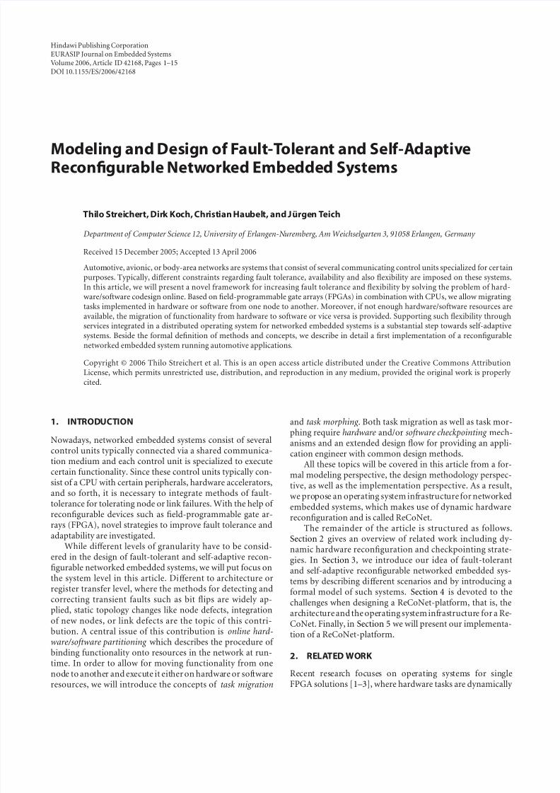
Figure 1: Diff erent scenarios in a ReCoNet. (a) A ReCoNet consisting of four nodes and six links with two communicating tasks. (b) Anadditional task t 3 was assigned to node n1. (c) The link (n1, n4) is broken. Thus, a new communication binding is mandatory. (d) The defectof node n4 requires a new task and communication binding.
Example 1. In Figure 1(a), a ReCoNet is given. The taskgraph g t is defined by V t = {t 1, t 2} and Et = {(t 1, t 2)}. The ar-chitecture graph consists of four nodes and six links, that is,V a = {n1, n2, n3, n4} and Ea = {{n1, n2}, {n1, n3}, {n1, n4},{n2, n3}, {n2, n4}, {n3, n4}}. The shown task binding is
βt = {(t 1, n1),(t 2, n4)}. Finally, the communication bindingis βc = {((t 1, t 2),({n1, n4}))}.
Starting from this example, diff erent scenarios can occur.In Figure 1(b) a new task t 3 is assigned to node n1. As this as-signment might violate given resource constraints (numberof logic elements available in an FPGA or number of tasks
assigned to a CPU), a new task binding βt can be demanded.A similar scenario can be induced by deassigning a task froma node.
Figure 1(c) shows another important scenario where thelink (n1, n4) is broken. Due to this defect, it is necessary tocalculate a new communication binding βc for the data de-pendency (t 1, t 2) which was previously routed over this link.In the example shown in Figure 1(c), the new communi-cation binding is βc((t 1, t 2)) = ({n1, n3}, {n3, n4}). Again asimilar scenario results from reestablishing a previously bro-ken link.
Finally, in Figure 1(d) a node defect is depicted. As noden4 is not available any longer, a new task binding βt for task
t 2 is mandatory. Moreover, changing the task binding im-plies the recalculation of the communication binding βc.The ReCoNet given in Figure 1(d) is given as follows:the task graph g t with V t = {t 1, t 2} and Et = {(t 1, t 2)},the architecture graph consisting of V a = {n1, n2, n3} andEa = {{n1, n2}, {n1, n3}, {n2, n3}}, the task binding βt =
{(t 1, n1),(t 2, n2)} and communication binding βc = {((t 1,t 2),({n1, n2}))}.
From these scenarios we conclude that a ReCoNet givenby a task graph g t , an architecture graph g a, the task bind-ing βt , and the communication binding βc might change ormight be changed over time, that is, g t = g t (τ ), g a = g a(τ ),
βt = βt (τ ), and βc = βc(τ ), where τ ∈ R+0 denotes the ac-tual time. In the following, we assume that a change in theapplication given by the task graph as well as a change in thearchitecture graph is indicated by an event e. Appropriately reacting to these events e is a feature of adaptive and fault tolerant systems.
The basic factors of innovation of a ReCoNet stem from(i) dynamic rerouting , (ii) hardware and software task mi- gration, (iii) hardware/software morphing , and (iv) online partitioning . These methods permit solving the problem of hardware/software codesign online, that is, at runtime. Notethat this is only possible due to the availability of dynamicand partial hardware reconfiguration. In the following, we
7/31/2019 Fault Tolerant ES Subramanian
http://slidepdf.com/reader/full/fault-tolerant-es-subramanian 4/15
4 EURASIP Journal on Embedded Systems
discuss the most important theoretical aspects of these meth-ods. In Section 4, we will describe the basic methods in moredetail.
3.2. Online partitioning
The goal of online partitioning is to equally distribute thecomputational workload in the network. To understand thisparticular problem, we have to take a closer look at the no-tion of task binding βt and communication binding βc. Wetherefore have to refine our model. In our model, we distin-guish a finite number of the so-called message types M . Eachmessage type m ∈ M corresponds to a communication pro-tocol in the ReCoNet.
Definition 2 (message type). M denotes a finite set of mes-sage types mi ∈ M .
In a ReCoNet supporting diff erent protocols and band-
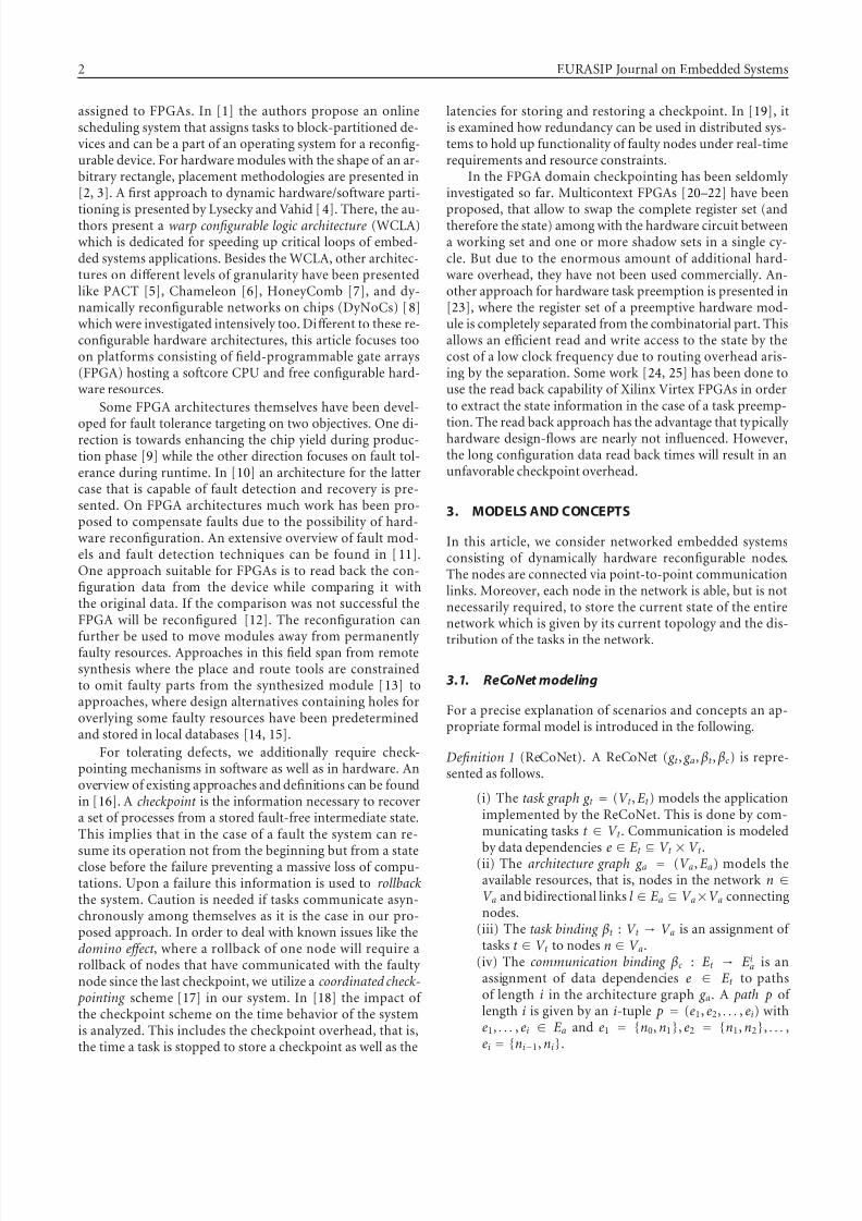
widths, it is crucial to distinguish diff erent demands. Assumea certain amount of data has to be transferred between twonodes in the ReCoNet. Between these nodes are two typesof networks, one which is dedicated for data transfer andsupports multicell packages and one which is dedicated for,for example, sensor values and therefore has a good pay-load/protocol ratio for one word messages. In such a case,the data which has to be transferred over two diff erent net-works would cause a diff erent traffic in each network. Hence,we associate with each data dependency e ∈ Et the so-calleddemand values which represent the required bandwidth whenusing a given message type.
Definition 3 (demand). With each pair (ei, m j) ∈ Et × M ,associate a real value d i, j ∈ R
+0 (possibly ∞ if the message
type cannot occur) indicating the demand for communica-tion bandwidth by the two communicating tasks t 1, t 2 withei = (t 1, t 2).
Example 2. Figure 2 shows a task graph consisting of threetasks with three demands. While the demand between t 1 andt 2 as well as thedemand between t 1and t 3 can be routed overall two message types (| M | = 2), the demand between t 2 andt 3 can be routed over the network that can transfer messagetype m2 only.
On the other hand, the supported bandwidth is modeledby the so-called capacities to each message type m ∈ M asso-ciated with a link l ∈ Ea in the architecture graph g a.
Definition 4 (capacity). With each pair (l i, m j) ∈ Ea × M ,associate a real value ci, j ∈ R
+0 (possibly 0, if the message type
cannot be routed over l i) indicating the capacity on a link l ifor message type m j .
In the following, we assume that for each link l i ∈ Ea
exactly one capacity ci is greater than 0.
Example 3. Figure 2 shows a ReCoNet consisting of fournodes and four links. While {n1, n3} and {n3, n4} can
t 1
t 3
t 2
n1
n2 n3
n4
d 2,1 = 10
d 2,2 = 15d 1,1 = 15
d 1,2 = 20
d 3,2 = 10
c 1 , 1
=
3 0
c2,2 = 15
c
3 , 2 =
1 0 c 4
, 1 = 2 0
Figure 2: Demands are associated with pairs of data dependenciesand message types while capacities are associated with pairs of linksand message types.
transfer the message type m1, {n2, n3} and {n2, n4} canhandle message type m2. As the data dependency (t 1, t 3) is
bound to path ({n1, n3}, {n3, n2}), node n3 acts as a gate-way. The gateway converts a message of type m1 to a messageof type m2. Note that only capacities with c > 0 and demandswith d < ∞ are shown in this figure. In our model, we assignexactly one capacity with c > 0 to each communication linkl ∈ Ea in the architecture graph g a and at least one demandwith d < ∞ to the data dependencies e ∈ Et in the task graph
g t .
Depending on the type of capacity, a demand of the cor-responding type can be routed over such an architecturegraph link. With this model refinement of a ReCoNet, it ispossible to limit the routing possibilities, and moreover, toassign diff erent demands to one problem graph edge.
Beside the communication, tasks have certain propertieswhich are of most importance in embedded systems. Thesecan be either soft or hard, either periodic or sporadic, havediff erent arrival times, diff erent workloads, and other con-straints, see, for example, [26]. For online partitioning a pre-cise definition of the workload is required which is known tobe a complex topic. As we are facing dynamically and par-tially reconfigurable architectures, we have to consider twotypes of workload, hardware workload and software workload,which are defined as follows.
Definition 5 (software workload). The software workloadwS(t , n) on node n produced by task t implemented in soft-ware is the fraction of execution time to its period.
This definition can be used for independent periodic andpreemptable tasks. Buttazzo [26] proposed a load definitionwhere the load is determined dynamically during runtime.The treatment of such definitions in our algorithm is a matterof future work.
Definition 6 (hardware workload). The hardware workloadwH (t , n) on node n produced by task t is defined as a frac-tion of the required area and maximal available area, respec-tively, configurable logic elements in case of FPGA imple-mentations.
7/31/2019 Fault Tolerant ES Subramanian
http://slidepdf.com/reader/full/fault-tolerant-es-subramanian 5/15
Thilo Streichert et al. 5
As a task t bound to node n, that is, (t , n) ∈ βt , can beimplemented partially in hardware and partially in software,diff erent implementations might exist.
Definition 7 (workload). The workload wi(t , n) on node nproduced by the ith implementation of task t is a pair
wi(t , n)=
(w
H
i (t , n), w
S
i (t , n)), where w
H
i (t , n) (w
S
i (t , n)) de-notes the hardware workload (software workload) on node nproduced by the ith implementation of task t .
The overall hardware/software workload on a node nin the network is the sum of all workloads of the t ith im-plementation of tasks bound to this node, that is, w(n) =
(t ,n)∈ βt wt i (t , n). Here, we assume constant workload de-
mands, that is, for all t ∈ T , wi(t , n) = wi(t ).With these definitions we can define the task of online
partitioning formally.
Definition 8 (online partitioning). The task of online parti-tioning solves the following multiobjective combinatorial op-
timization problem at runtime:
min
⎛⎜⎜⎜⎜⎜⎜⎜⎝
maxΔn(wH (n)
,Δn
wS(n)
n
wH (n) −
n
wS(n)
n
wH (n) + wS(n)
⎞⎟⎟⎟⎟⎟⎟⎟⎠ , (1)
such that
wH (n), wS(n) ≤ 1,
βt is a feasible task binding,
βc is a feasible communication binding.
(2)
The first objective describes the workload balance inthe network. With this objective to be minimized, theload in the network is balanced between the nodes, wherehardware and software loads are treated separately withΔn(wH (n)) = maxn(wH (n)) − minn(wH (n)) and Δn(wS(n)) =
maxn(wS(n)) − minn(wS(n)).The second objective balances the load between hard-
ware and software. With this strategy, there will always be agood load reserve on each active node which is important forachieving fast repair times in case of unknown future nodeor link failures.
The third objective reduces the total load in the network.Finally, the constraints imposed on the solutions guaranteethat not more than 100% workload can be assigned to a sin-gle node. The two feasibility requirements will be discussedin more detail next.
A feasible binding guarantees that communications de-manded by the problem graph can be established in the allo-cated architecture. This is an important property in explicitmodeling of communication.
Definition 9 (feasible task binding). Given a task graph g t andan architecture graph g a, a feasible task binding βt is an as-signment of tasks t ∈ V t to nodes n ∈ V a that satisfies thefollowing requirements:
(i) each task t ∈ V t is assigned to exactly one node n ∈
V a, that is, for all t ∈ V t , |{(t , n) ∈ βt | n ∈ V a}| = 1;
(ii) for each data dependency e ∈ (t i, t j) ∈ Et with(t i, ni), (t j , n j) ∈ βt a path p from ni to n j exists.
This definition diff ers from the concepts of feasible bind-ing presented in [27] in a way that communicating processesrequire a path in the architecture graph and not a direct linkfor establishing this communication. This way, we are ableto consider networked embedded systems. However, consid-ering multihop communication, we have to regard the ca-pacity of connections and data demands of communication.This step will be named communication binding in the fol-lowing.
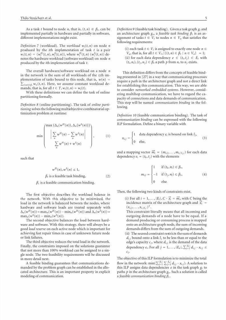
Definition 10 (feasible communication binding). The task of communication binding can be expressed with the followingILP formulation. Define a binary variable with
xi, j =
⎧⎪⎨⎪⎩1 data dependency ei is bound on link l j ,
0 else,(3)
and a mapping vector −→mi = (mi,1, . . . , mi,|V a|) for each datadependency ei = (t k, t j) with the elements
mi,l =
⎧⎪⎪⎪⎪⎨⎪⎪⎪⎪⎩1 if (t k, nl ) ∈ βt ,
−1 if (t j , nl ) ∈ βt ,
0 else.
(4)
Then, the following two kinds of constraints exist.
(i) For all i = 1, . . . , |Et |, C ·−→xi =
−→mi, with C being theincidence matrix of the architecture graph and −→xi =
(xi, j , . . . , xi,|Ea|)T .
This constraint literally means that all incoming andoutgoing demands of a node have to be equal. If ademand producing or consuming process is mapped
onto an architecture graph node, the sum of incomingdemands diff ers from the sum of outgoing demands.
(ii) The second constraint restricts the sum of demandsd i, j bound onto a link l j to be less than or equal to theedge’s capacity c j , where d i, j is the demand of the data
dependency ei. For all j = 1, . . . , |Ea|,|Et |
i=1 d i, j · xi, j ≤
c j .
The objective of this ILP formulation is to minimize the total
flow in the network: min(|Et |
i=1
|Ea| j=1 d i, j · xi, j). A solution to
this ILP assigns data dependencies e in the task graph g t topaths p in the architecture graph g a. Such a solution is calleda feasible communication binding βc.
7/31/2019 Fault Tolerant ES Subramanian
http://slidepdf.com/reader/full/fault-tolerant-es-subramanian 6/15
6 EURASIP Journal on Embedded Systems
Z S
T S
T S 1
Z
Z M T H
T H 1
Z H
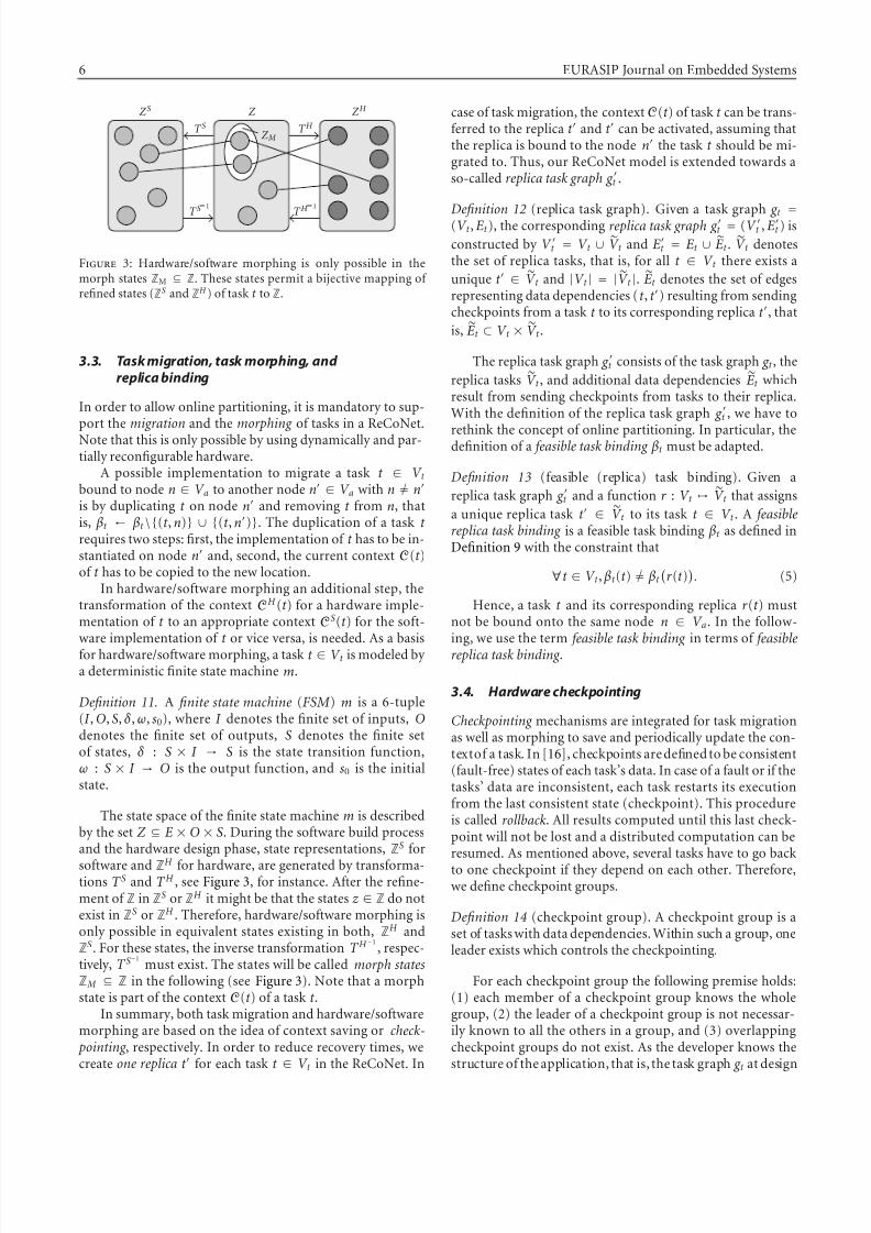
Figure 3: Hardware/software morphing is only possible in themorph states ZM ⊆ Z. These states permit a bijective mapping of refined states (ZS and ZH ) of task t to Z.
3.3. Task migration, task morphing, and replica binding
In order to allow online partitioning, it is mandatory to sup-port the migration and the morphing of tasks in a ReCoNet.Note that this is only possible by using dynamically and par-tially reconfigurable hardware.
A possible implementation to migrate a task t ∈ V t
bound to node n ∈ V a to another node n ∈ V a with n = n
is by duplicating t on node n and removing t from n, thatis, βt ← βt \{(t , n)} ∪ {(t , n)}. The duplication of a task t requires two steps: first, the implementation of t has to be in-stantiated on node n and, second, the current context C(t )of t has to be copied to the new location.
In hardware/software morphing an additional step, thetransformation of the context CH (t ) for a hardware imple-mentation of t to an appropriate context CS(t ) for the soft-ware implementation of t or vice versa, is needed. As a basisfor hardware/software morphing, a task t ∈ V t is modeled by a deterministic finite state machine m.
Definition 11. A finite state machine (FSM ) m is a 6-tuple(I , O, S, δ , ω, s0), where I denotes the finite set of inputs, Odenotes the finite set of outputs, S denotes the finite setof states, δ : S × I → S is the state transition function,ω : S × I → O is the output function, and s0 is the initialstate.
The state space of the finite state machine m is describedby the set Z ⊆ E × O × S. During the software build processand the hardware design phase, state representations, ZS for
software and ZH for hardware, are generated by transforma-tions T S and T H , see Figure 3, for instance. After the refine-ment of Z in ZS or ZH it might be that the states z ∈ Z do notexist in ZS or ZH . Therefore, hardware/software morphing isonly possible in equivalent states existing in both, ZH andZ
S. For these states, the inverse transformation T H −1, respec-
tively, T S−1
must exist. The states will be called morph statesZ M ⊆ Z in the following (see Figure 3). Note that a morphstate is part of the context C(t ) of a task t .
In summary, both task migration and hardware/softwaremorphing are based on the idea of context saving or check- pointing , respectively. In order to reduce recovery times, wecreate one replica t for each task t ∈ V t in the ReCoNet. In
case of task migration, the contextC(t ) of task t can be trans-ferred to the replica t and t can be activated, assuming thatthe replica is bound to the node n the task t should be mi-grated to. Thus, our ReCoNet model is extended towards aso-called replica task graph g t .
Definition 12 (replica task graph). Given a task graph g t =
(V t , Et ), the corresponding replica task graph g t = (V t , Et ) is
constructed by V t = V t ∪ V t and Et = Et ∪ Et . V t denotes
the set of replica tasks, that is, for all t ∈ V t there exists a
unique t ∈ V t and |V t | = | V t |. Et denotes the set of edgesrepresenting data dependencies (t , t ) resulting from sendingcheckpoints from a task t to its corresponding replica t , that
is, Et ⊂ V t × V t .
The replica task graph g t consists of the task graph g t , the
replica tasks V t , and additional data dependencies Et whichresult from sending checkpoints from tasks to their replica.With the definition of the replica task graph g t , we have to
rethink the concept of online partitioning. In particular, thedefinition of a feasible task binding βt must be adapted.
Definition 13 (feasible (replica) task binding). Given a
replica task graph g t and a function r : V t → V t that assigns
a unique replica task t ∈ V t to its task t ∈ V t . A feasiblereplica task binding is a feasible task binding βt as defined inDefinition 9 with the constraint that
∀t ∈ V t , βt (t ) = βt
r (t )
. (5)
Hence, a task t and its corresponding replica r (t ) mustnot be bound onto the same node n ∈ V a. In the follow-ing, we use the term feasible task binding in terms of feasiblereplica task binding .
3.4. Hardware checkpointing
Checkpointing mechanisms are integrated for task migrationas well as morphing to save and periodically update the con-textof a task. In [16], checkpoints are defined to be consistent(fault-free) states of each task’s data. In case of a fault or if thetasks’ data are inconsistent, each task restarts its executionfrom the last consistent state (checkpoint). This procedureis called rollback. All results computed until this last check-point will not be lost and a distributed computation can beresumed. As mentioned above, several tasks have to go backto one checkpoint if they depend on each other. Therefore,we define checkpoint groups.
Definition 14 (checkpoint group). A checkpoint group is aset of tasks with data dependencies. Within such a group, oneleader exists which controls the checkpointing.
For each checkpoint group the following premise holds:(1) each member of a checkpoint group knows the wholegroup, (2) the leader of a checkpoint group is not necessar-ily known to all the others in a group, and (3) overlappingcheckpoint groups do not exist. As the developer knows thestructure of the application, that is, the task graph g t at design
7/31/2019 Fault Tolerant ES Subramanian
http://slidepdf.com/reader/full/fault-tolerant-es-subramanian 7/15
Thilo Streichert et al. 7
time, checkpoint groups can be built a priori. Thus, proto-cols for establishing checkpoint groups during runtime arenot considered in this case.
Model of Consistency
Assume a task graph g t with a set of tasks V t = {t 0, t 1, t 2}running on diff erent nodes in a ReCoNet. The first task t 0produces messages and sends them to the next task t 1 whichperforms some computation on the message’s content andsends them further to task t 2. Our communication model isbased on message queues for the intertask communication.Due to rerouting mechanisms, for example, in case of a linkdefect, it is possible that messages were sent over diff erentlinks. Hence, the order of messages in general cannot be as-sured to stay the same.
But if messages arrive at a task t j , we have to ensure thatthese were processed in the same order they have been cre-ated by task t j−1. As a consequence, we assign a consecutive
identifier i to every generated message. Let us assume thatthe last processed message by a task t j was mi produced attask t j−1, then task t j has to process message mi+1 next. If the message order arranged by task t j−1 has changed duringcommunication this will be recognized at task t j by an iden-tifier larger than the one to be processed next. In this caseall messages mi+k, for all k > 1 will be temporarily stored inthe so-called local data set of task t j to be processed later incorrect order.
If task t j receives a message to store a checkpoint by theleader of a checkpoint group it will stop to process the nextmessages and consequently t j will stop to produce new out-put messages for node t j+1. In the following, all tasks of thischeckpoint group will start to move incoming messages intotheir local data set. In addition, all tasks of the checkpointgroup will store their internal states on the local data set. Asa consequence, all tasks of the checkpoint group will reach aconsistent state.
Hence, we define a checkpoint as follows.
Definition 15 (checkpoint). A checkpoint is a set of local datasets. It can be produced if all tasks inside a checkpoint groupare in a consistent state. This is when (i) all message pro-ducing tasks are stopped and (ii) after all message queues areempty.
The checkpoint is stored in a distributed manner in the
local data sets of all tasks belonging to their checkpointgroup. All tasks t ∈ V t of the task graph g t will have to copy their current local data set to their corresponding replica taskt ∈ V t of the replica task graph g t . If a node hosting a task t fails, the corresponding replica task t 0 takes over the work of t and all tasks of the checkpoint group will perform a rollbackby restoring their last checkpoint.
Hardware checkpointing
As we model tasks’ behavior by finite state machines andwe have seen how to handle input and output data to keepcheckpoints consistent, we are now able to present a new
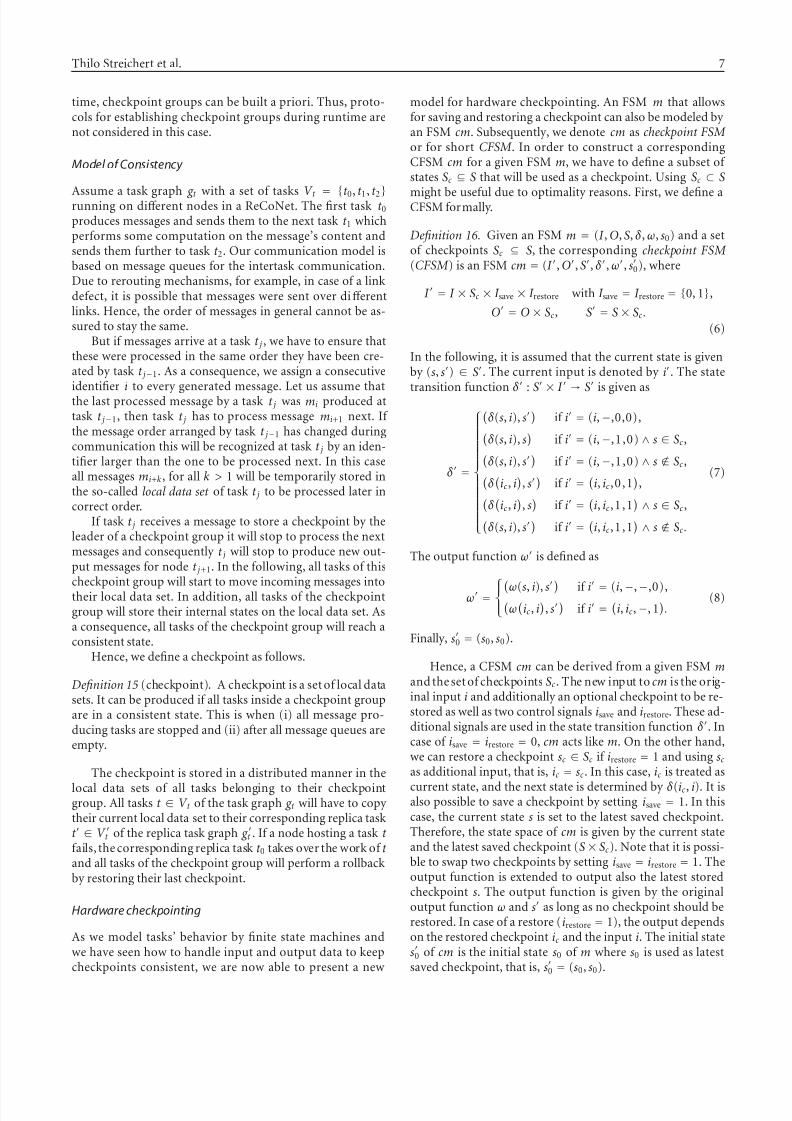
model for hardware checkpointing. An FSM m that allowsfor saving and restoring a checkpoint can also be modeled by an FSM cm. Subsequently, we denote cm as checkpoint FSM or for short CFSM . In order to construct a correspondingCFSM cm for a given FSM m, we have to define a subset of states Sc ⊆ S that will be used as a checkpoint. Using Sc ⊂ S
might be useful due to optimality reasons. First, we define aCFSM formally.
Definition 16. Given an FSM m = (I , O, S, δ , ω, s0) and a setof checkpoints Sc ⊆ S, the corresponding checkpoint FSM (CFSM ) is an FSM cm = (I , O, S, δ , ω, s
0), where
I = I × Sc × I save × I restore with I save = I restore = {0, 1},
O = O × Sc, S = S × Sc.
(6)
In the following, it is assumed that the current state is givenby (s, s) ∈ S. The current input is denoted by i. The state
transition function δ
: S ×
I →
S
is given as
δ =
⎧⎪⎪⎪⎪⎪⎪⎪⎪⎪⎪⎪⎪⎪⎨⎪⎪⎪⎪⎪⎪⎪⎪⎪⎪⎪⎪⎪⎩
δ (s, i), s
if i = (i, −,0,0),
δ (s, i), s
if i = (i, −,1,0) ∧ s ∈ Sc,δ (s, i), s
if i = (i, −,1,0) ∧ s / ∈ Sc,
δ
ic, i
, s
if i =
i, ic,0 ,1
,δ
ic, i
, s
if i =
i, ic,1 ,1
∧ s ∈ Sc,δ (s, i), s
if i =
i, ic,1 ,1
∧ s / ∈ Sc.
(7)
The output function ω is defined as
ω = ⎧⎨⎩ω(s, i), s if i
= (i, −, −,0),ω
ic, i
, s
if i =
i, ic, −, 1
.(8)
Finally, s0 = (s0, s0).
Hence, a CFSM cm can be derived from a given FSM mand the set of checkpoints Sc. The new input to cm is the orig-inal input i and additionally an optional checkpoint to be re-stored as well as two control signals isave and irestore. These ad-ditional signals are used in the state transition function δ . Incase of isave = irestore = 0, cm acts like m. On the other hand,we can restore a checkpoint sc ∈ Sc if irestore = 1 and using sc
as additional input, that is, ic = sc. In this case, ic is treated as
current state, and the next state is determined by δ (ic, i). It isalso possible to save a checkpoint by setting isave = 1. In thiscase, the current state s is set to the latest saved checkpoint.Therefore, the state space of cm is given by the current stateand the latest saved checkpoint (S × Sc). Note that it is possi-ble to swap two checkpoints by setting isave = irestore = 1. Theoutput function is extended to output also the latest storedcheckpoint s. The output function is given by the originaloutput function ω and s as long as no checkpoint should berestored. In case of a restore (irestore = 1), the output dependson the restored checkpoint ic and the input i. The initial states
0 of cm is the initial state s0 of m where s0 is used as latestsaved checkpoint, that is, s
0 = (s0, s0).
7/31/2019 Fault Tolerant ES Subramanian
http://slidepdf.com/reader/full/fault-tolerant-es-subramanian 8/15
8 EURASIP Journal on Embedded Systems
0 1
23
/ 0
/ 1
/ 2
/ 3
(a)
0, 0 1, 0
2, 03, 0
0, 2
3, 2
1, 2
2, 2
(
, 0 , 0 ) / ( 3 , 0 )
( ,0,0) / (0,0)
( ,0,0) / (2,0)
(
, 0 , 0 ) / ( 1 , 0 )
( ,1,0) / (0,2)
(
, 0 , 0 ) / ( 3 , 2 )
( ,1,0) / (2,0)
( ,0,0) / (0,2)
(
, 0 , 0 ) / ( 1 , 2 )
( ,0,0) / (2,2)
(0,0,1) / (0,0)
(2,0,1) / (2,0)
(0,0,1) / (0,2)
(2,0,1) / (2,2)
(b)
Figure 4: (a) FSM of a modulo-4-counter. (b) CorrespondingCFSM for Sc = {0, 2}, that is, only in states 0 and 2 saving of thecheckpoint is permitted. The state space is given by the actual stateand the latest saved checkpoint.
Example 4. Figure 4(a) shows a modulo-4-counter. Its FSMm is given by I = ∅, O = S = {0,1,2,3}, δ (s) = (s + 1)%4,
ω(s) = s, and s0 = 0. The corresponding CFSM cm forSc = {0, 2} is shown in Figure 4. For readability reasons, wehave omitted the swap state transitions. The state space hasbeen doubled due to the two possible checkpoints. To be pre-cise, there are two copies of m, one representing s = 0 tobe the latest stored checkpoint and one representing s = 2being the latest stored checkpoint. We can see that there ex-ist two state transitions connecting these copied FSMs whensaving a checkpoint, that is, ((2, 0), (3, 2)) and ((0, 2), (1, 0)).Of course it is possible to save the checkpoints in the states(0, 0) and (2, 2) as well. But the resulting state transitions donot diff er from the normal mode transitions. The restoringof a checkpoint results in additional state transitions.
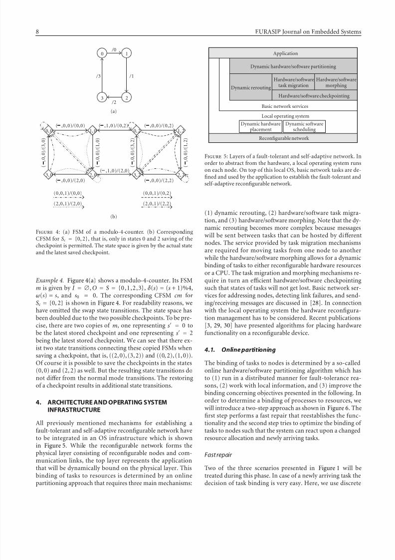
4. ARCHITECTURE AND OPERATING SYSTEMINFRASTRUCTURE
All previously mentioned mechanisms for establishing afault-tolerant and self-adaptive reconfigurable network haveto be integrated in an OS infrastructure which is shownin Figure 5. While the reconfigurable network forms thephysical layer consisting of reconfigurable nodes and com-munication links, the top layer represents the applicationthat will be dynamically bound on the physical layer. Thisbinding of tasks to resources is determined by an onlinepartitioning approach that requires three main mechanisms:
Application
Dynamic hardware/software partitioning
Dynamic rerouting
Hardware/softwaretask migration
Hardware/softwaremorphing
Hardware/software checkpointingBasic network services
Local operating system
Dynamic hardwareplacement
Dynamic softwarescheduling
Reconfigurable network
Figure 5: Layers of a fault-tolerant and self-adaptive network. Inorder to abstract from the hardware, a local operating system runson each node. On top of this local OS, basic network tasks are de-fined and used by the application to establish the fault-tolerant andself-adaptive reconfigurable network.
(1) dynamic rerouting, (2) hardware/software task migra-tion, and (3) hardware/software morphing. Note that the dy-namic rerouting becomes more complex because messageswill be sent between tasks that can be hosted by diff erentnodes. The service provided by task migration mechanismsare required for moving tasks from one node to anotherwhile the hardware/software morphing allows for a dynamicbinding of tasks to either reconfigurable hardware resourcesor a CPU. The task migration and morphing mechanisms re-quire in turn an efficient hardware/software checkpointingsuch that states of tasks will not get lost. Basic network ser-
vices for addressing nodes, detecting link failures, and send-ing/receiving messages are discussed in [28]. In connectionwith the local operating system the hardware reconfigura-tion management has to be considered. Recent publications[3, 29, 30] have presented algorithms for placing hardwarefunctionality on a reconfigurable device.
4.1. Online partitioning
The binding of tasks to nodes is determined by a so-calledonline hardware/software partitioning algorithm which hasto (1) run in a distributed manner for fault-tolerance rea-sons, (2) work with local information, and (3) improve the
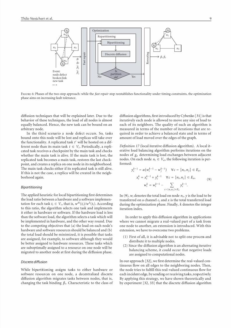
binding concerning objectives presented in the following. Inorder to determine a binding of processes to resources, wewill introduce a two-step approach as shown in Figure 6. Thefirst step performs a fast repair that reestablishes the func-tionality and the second step tries to optimize the binding of tasks to nodes such that the system can react upon a changedresource allocation and newly arriving tasks.
Fast repair
Two of the three scenarios presented in Figure 1 will betreated during this phase. In case of a newly arriving task thedecision of task binding is very easy. Here, we use discrete
7/31/2019 Fault Tolerant ES Subramanian
http://slidepdf.com/reader/full/fault-tolerant-es-subramanian 9/15
Thilo Streichert et al. 9
t 1
t 2
n1
n2 n3
n4
Event:node defectbroken linknew task
g t
g a
βt
βc
F a s t r e p a i r
Optimization
Repartitioning
Bipartitioning
Discrete diff usion
No Yes
Ispartition
ok?
R e r o u
t i n g
t 1
t 2
n1
n2 n3
βt βc
Figure 6: Phases of the two-step approach: while the fast repair step reestablishes functionality under timing constraints, the optimizationphase aims on increasing fault tolerance.
diff usion techniques that will be explained later. Due to thebehavior of these techniques, the load of all nodes is almostequally balanced. Hence, the new task can be bound on anarbitrary node.
In the third scenario a node defect occurs. So, tasksbound onto this node will be lost and replicas will take overthe functionality. A replicated task t will be hosted on a dif-ferent node than its main task t ∈ V t . Periodically, a repli-cated task receives a checkpoint by the main task and checkswhether the main task is alive. If the main task is lost, thereplicated task becomes a main task, restores the last check-point, and creates a replica on one node in its neighborhood.The main task checks either if its replicated task is still alive.
If this is not the case, a replica will be created in the neigh-borhood again.
Bipartitioning
The applied heuristic for local bipartitioning first determinesthe load ratio between a hardware and a software implemen-tation for each task t i ∈ V t , that is, wH (t i) /wS(t i). Accordingto this ratio, the algorithm selects one task and implementsit either in hardware or software. If the hardware load is lessthan the software load, the algorithm selects a task which willbe implemented in hardware, and the other way round. Dueto the competing objectives that (a) the load on each node’s
hardware and software resources should be balanced and (b)the total load should be minimized, it is possible that tasksare assigned, for example, to software although they wouldbe better assigned to hardware resources. These tasks whichare suboptimally assigned to a resource on one node will bemigrated to another node at first during the diff usion phase.
Discrete diffusion
While bipartitioning assigns tasks to either hardware orsoftware resources on one node, a decentralized discretediff usion algorithm migrates tasks between nodes, that is,changing the task binding βt . Characteristic to the class of
diff usion algorithms, first introduced by Cybenko [31] is thatiteratively each node is allowed to move any size of load toeach of its neighbors. The quality of such an algorithm ismeasured in terms of the number of iterations that are re-quired in order to achieve a balanced state and in terms of amount of load moved over the edges of the graph.
Definition 17 (local iterative diff usion algorithm). A local it-erative load balancing algorithm performs iterations on thenodes of g a determining load exchanges between adjacentnodes. On each node ni ∈ V a, the following iteration is per-formed:
yk−1c = αwk−1
i − wk−1 j ∀c = ni, n j ∈ Ea,
xkc = xk−1
c + yk−1c ∀c =
ni, n j
∈ Ea,
wki = wk−1
i −
c={ni,n j }∈Ea
yk−1c .
(9)
In (9), wi denotes the total load on node ni, y is the load to betransferred on a channel c, and x is the total transferred loadduring the optimization phase. Finally, k denotes the integeriteration index.
In order to apply this diff usion algorithm in applicationswhere we cannot migrate a real-valued part of a task fromone node to another, an extension is introduced. With this
extension, we have to overcome two problems.
(1) First of all, it is advisable not to split one process anddistribute it to multiple nodes.
(2) Since the diff usion algorithm is an alternating iterativebalancing scheme, it could occur that negative loadsare assigned to computational nodes.
In our approach [32], we first determine the real-valued con-tinuous flow on all edges to the neighboring nodes. Then,the node tries to fulfill this real-valued continuous flow foreach incident edge, by sending or receiving tasks, respectively.By applying this strategy, we have shown theoretically andby experiment [32, 33] that the discrete diff usion algorithm
7/31/2019 Fault Tolerant ES Subramanian
http://slidepdf.com/reader/full/fault-tolerant-es-subramanian 10/15
10 EURASIP Journal on Embedded Systems
121086420
Iteration
0.001
0.01
0.1
1
10
100
D i s t a
n c e
100 load
150 load
200 load
250 load
500 load
(a)
121086420
Iteration
0.01
0.1
1
10
100
D i s t a n c e
10 tasks
20 tasks
50 tasks
100 tasks
500 tasks
1000 tasks
(b)
Figure 7: Presented is the distance between the solutions of ourdistributed online hardware/software partitioning approach and analgorithm with global knowledge. In (a) tasks are bound to networknodes such that each node has a certain load. In (b) a certain num-ber of tasks is bound to each node and each task is implemented in
the optimal implementation style.
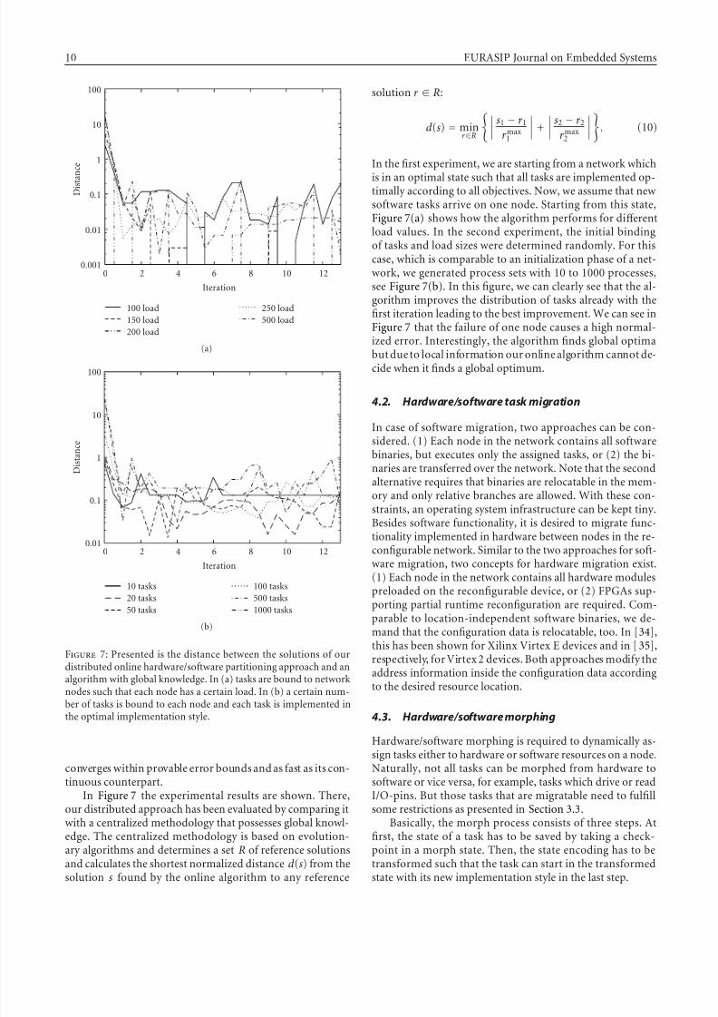
converges within provable error bounds and as fast as its con-tinuous counterpart.
In Figure 7 the experimental results are shown. There,our distributed approach has been evaluated by comparing itwith a centralized methodology that possesses global knowl-edge. The centralized methodology is based on evolution-ary algorithms and determines a set R of reference solutionsand calculates the shortest normalized distance d (s) from thesolution s found by the online algorithm to any reference
solution r ∈ R:
d (s) = minr ∈R
s1 − r 1r max
1
+
s2 − r 2r max
2
. (10)
In the first experiment, we are starting from a network which
is in an optimal state such that all tasks are implemented op-timally according to all objectives. Now, we assume that newsoftware tasks arrive on one node. Starting from this state,Figure 7(a) shows how the algorithm performs for diff erentload values. In the second experiment, the initial bindingof tasks and load sizes were determined randomly. For thiscase, which is comparable to an initialization phase of a net-work, we generated process sets with 10 to 1000 processes,see Figure 7(b). In this figure, we can clearly see that the al-gorithm improves the distribution of tasks already with thefirst iteration leading to the best improvement. We can see inFigure 7 that the failure of one node causes a high normal-ized error. Interestingly, the algorithm finds global optima
but due to local information our online algorithm cannot de-cide when it finds a global optimum.
4.2. Hardware/software task migration
In case of software migration, two approaches can be con-sidered. (1) Each node in the network contains all softwarebinaries, but executes only the assigned tasks, or (2) the bi-naries are transferred over the network. Note that the secondalternative requires that binaries are relocatable in the mem-ory and only relative branches are allowed. With these con-straints, an operating system infrastructure can be kept tiny.Besides software functionality, it is desired to migrate func-
tionality implemented in hardware between nodes in the re-configurable network. Similar to the two approaches for soft-ware migration, two concepts for hardware migration exist.(1) Each node in the network contains all hardware modulespreloaded on the reconfigurable device, or (2) FPGAs sup-porting partial runtime reconfiguration are required. Com-parable to location-independent software binaries, we de-mand that the configuration data is relocatable, too. In [34],this has been shown for Xilinx Virtex E devices and in [35],respectively, for Virtex 2 devices. Both approaches modify theaddress information inside the configuration data accordingto the desired resource location.
4.3. Hardware/software morphing
Hardware/software morphing is required to dynamically as-sign tasks either to hardware or software resources on a node.Naturally, not all tasks can be morphed from hardware tosoftware or vice versa, for example, tasks which drive or readI/O-pins. But those tasks that are migratable need to fulfillsome restrictions as presented in Section 3.3.
Basically, the morph process consists of three steps. Atfirst, the state of a task has to be saved by taking a check-point in a morph state. Then, the state encoding has to betransformed such that the task can start in the transformedstate with its new implementation style in the last step.
7/31/2019 Fault Tolerant ES Subramanian
http://slidepdf.com/reader/full/fault-tolerant-es-subramanian 11/15
Thilo Streichert et al. 11
A requirement to morphable tasks is that they have to beequivalent such that the surrounding system does not rec-ognize the implementation style of the morphable task. Alsothe transformation depends heavily on the implementationwhich especially leads to problems when transforming datatypes. While it is possible to represent numbers in hardware
with almost arbitrary word width, current processors per-form computations on 16 bit or 32 bit wide words. Thus,the numbers have to be extended or truncated. This modi-fication causes again difficulties if numbers are presented indiff erent representations. The representation which can ei-ther be one’s complements, two’s complement, fixed point,or floating point numbers needs to be transformed, too.Additional complexity arises if functionality requires a se-quential computation in software and a parallel computationin hardware. Due to these implementation-dependent con-straints, we currently support an automated morph-functiongeneration only for bit vectors in the hardware that are in-terpreted as integers in the software. The designer needs to
give information about the possible morph states and to-gether with the help of the automated insertion of check-points into hardware/software tasks, the morphing becomespossible.
4.4. Hardware checkpointing
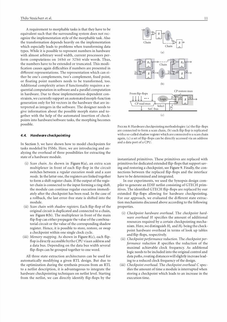
In Section 3, we have shown how to model checkpoints fortasks modeled by FSMs. Here, we are introducing and an-alyzing the overhead of three possibilities for extracting thestate of a hardware module.
(i) Scan chain. As shown in Figure 8(a), an extra scan
multiplexer in front of each flip-flop in the circuitswitches between a regular execution mode and a scanmode. In the latter one, the registers are linked togetherto form a shift register chain. If the output of the regis-ter chain is connected to the input forming a ring shift,the module can continue regular execution immedi-ately after the checkpoint has been read. In the case of a rollback, the last error-free state is shifted into themodule.
(ii) Scan chain with shadow registers. Each flip-flop of theoriginal circuit is duplicated and connected to a chain,see Figure 8(b). The multiplexer in front of the mainflip flop can either propagate the value of the combina-
torial circuit or the value of the corresponding shadowregister. Hence, it is possible to store, restore, or swapa checkpoint within one single clock cycle.
(iii) Memory mapping . As shown in Figure 8(c), each flip-flop is directly accessible bythe CPU viaan address anda data bus. Depending on the data bus width severalflip-flops can be grouped together to one word.
All three state extraction architectures can be used forautomatically modifying a given RTL design. But due tothe optimization during the synthesis process from an RTLto a netlist description, it is advantageous to integrate thehardware checkpointing techniques on netlist level. Startingfrom the netlist, we can directly identify flip-flops by the
L o g i c
L o g i c
Chain
Chain
R
R
(a)
L o g i c
Chain
R R
RS RS
DDD DQ Q
(b)
Logic RDD Q
C P i n
From flip-flopsCP restore mux
CP read muxSelect
SoC-bus
(c)
Figure 8: Hardware checkpointing methodologies: (a) the flip-flopsare connected to form a scan chain, (b) each flip flop is replicatedwith a so-called shadow register which are connected to a scan chainagain, (c) a set of flip-flops can be directly accessed via an addressand a data port of a CPU.
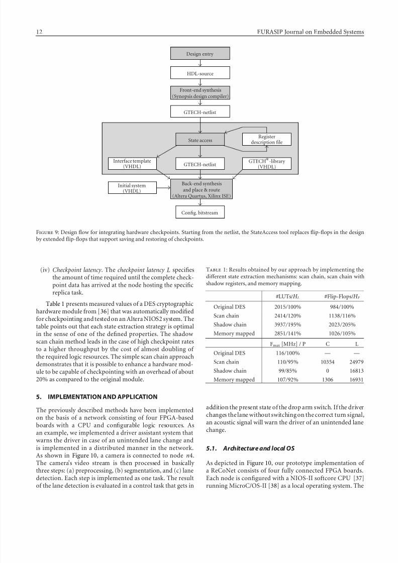
instantiated primitives. These primitives are replaced withprimitives for dedicated extended flip-flops that support sav-
ing and restoring a checkpoint, see Figure 9. Finally, the con-nections between the replaced flip-flops and the interfacehave to be determined and integrated.
In our experiments, we used the Synopsis design com-piler to generate an EDIF netlist consisting of GTECH prim-itives. The identified GTECH flip-flops are replaced by ourextended flip-flops allowing for hardware checkpointing.For our approach, we evaluated the diff erent state extrac-tion mechanisms discussed above according to the followingproperties.
(i) Checkpoint hardware overhead. The checkpoint hard-ware overhead H specifies the amount of additionalresources required by a certain checkpointing mecha-
nism. Here, we distinguish H L and H F being the check-point hardware overhead in terms of look up tablesand flip-flops, respectively.
(ii) Checkpoint performance reduction. The checkpoint per- formance reduction R specifies the reduction of themaximal achievable clock frequency. As additionallogic needs to be included into the original control anddata paths, routing distances will slightly increase lead-ing to a reduced clock frequency of the design.
(iii) Checkpoint overhead. The checkpoint overhead C spec-ifies the amount of time a module is interrupted whenstoring a checkpoint which leads to an increase in theexecution time.
7/31/2019 Fault Tolerant ES Subramanian
http://slidepdf.com/reader/full/fault-tolerant-es-subramanian 12/15
12 EURASIP Journal on Embedded Systems
Design entry
HDL-source
Front-end synthesis
(Synopsis design compiler)
GTECH-netlist
State accessRegister
description file
Interface template(VHDL) GTECH-netlist
GTECH -library (VHDL)
Initial system(VHDL)
Back-end synthesisand place & route
(Altera Quartus, Xilinx ISE)
Config. bitstream
Figure 9: Design flow for integrating hardware checkpoints. Starting from the netlist, the StateAccess tool replaces flip-flops in the designby extended flip-flops that support saving and restoring of checkpoints.
(iv) Checkpoint latency . The checkpoint latency L specifiesthe amount of time required until the complete check-point data has arrived at the node hosting the specific
replica task.Table 1 presents measured values of a DES cryptographic
hardware module from [36] that was automatically modifiedfor checkpointing and tested on an Altera NIOS2 system. Thetable points out that each state extraction strategy is optimalin the sense of one of the defined properties. The shadowscan chain method leads in the case of high checkpoint ratesto a higher throughput by the cost of almost doubling of the required logic resources. The simple scan chain approachdemonstrates that it is possible to enhance a hardware mod-ule to be capable of checkpointing with an overhead of about20% as compared to the original module.
5. IMPLEMENTATION AND APPLICATION
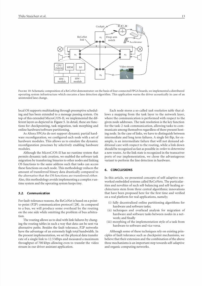
The previously described methods have been implementedon the basis of a network consisting of four FPGA-basedboards with a CPU and configurable logic resources. Asan example, we implemented a driver assistant system thatwarns the driver in case of an unintended lane change andis implemented in a distributed manner in the network.As shown in Figure 10, a camera is connected to node n4.The camera’s video stream is then processed in basically three steps: (a) preprocessing, (b) segmentation, and (c) lanedetection. Each step is implemented as one task. The resultof the lane detection is evaluated in a control task that gets in
Table 1: Results obtained by our approach by implementing thediff erent state extraction mechanisms: scan chain, scan chain withshadow registers, and memory mapping.
#LUTs/H L #Flip-Flops/H F
Original DES 2015 / 100% 984 / 100%
Scan chain 2414 / 120% 1138 / 116%
Shadow chain 3937 / 195% 2023 / 205%
Memory mapped 2851 / 141% 1026 / 105%
Fmax [MHz] / P C L
Original DES 116 / 100% — —
Scan chain 110 / 95% 10354 24979
Shadow chain 99 / 85% 0 16813
Memory mapped 107 / 92% 1306 16931
addition the present state of the drop arm switch. If the driverchanges the lane without switching on the correct turn signal,an acoustic signal will warn the driver of an unintended lanechange.
5.1. Architecture and local OS
As depicted in Figure 10, our prototype implementation of a ReCoNet consists of four fully connected FPGA boards.Each node is configured with a NIOS-II softcore CPU [37]running MicroC/OS-II [38] as a local operating system. The
7/31/2019 Fault Tolerant ES Subramanian
http://slidepdf.com/reader/full/fault-tolerant-es-subramanian 13/15
Thilo Streichert et al. 13
n1
n2
n3
n4
Cockpit
Accelerator
Video stream
Drop-armswitch
ReCoNetlink
CPU(NIOS) MEM IO
HW-module
HW-module
Figure 10: Schematic composition of a ReCoNet demonstrator: on the basis of four connected FPGA boards, we implemented a distributedoperating system infrastructure which executes a lane detection algorithm. This application warns the driver acoustically in case of anunintended lane change.
local OS supports multitasking through preemptive schedul-ing and has been extended to a message passing system. Ontop of this extended MicroC/OS-II, we implemented the dif-ferent layers as depicted in Figure 5. In detail, these are func-tions for checkpointing, task migration, task morphing andonline hardware/software partitioning.
As Altera FPGAs do not support dynamic partial hard-ware reconfiguration, we configured each node with a set of hardware modules. This allows us to emulate the dynamicreconfiguration processes by selectively enabling hardware
modules.Although the MicroC/OS-II has no runtime system thatpermits dynamic task creation, we enabled the software taskmigration by transferring binaries to other nodes and linkingOS functions to the same address such that tasks can accessthese functions on each node. This methodology reduces theamount of transferred binary data drastically compared tothe alternative that the OS functions are transferred either.Also, this methodology avoids implementing a complex run-time system and the operating system keeps tiny.
5.2. Communication
For fault-tolerance reasons, the ReCoNet is based on a point-to-point (P2P) communication protocol [28]. As comparedto a bus, we will produce some overhead by the routingon the one side while omitting the problem of bus arbitra-tion.
The routing allows us to deal with link failures by chang-ing the routing tables in such a way that data can be sent viaalternative paths. Besides the fault tolerance, P2P networkshave the advantage of an extremely high total bandwidth. Inthe present implementation, we set the physical data transferrate of a single link to 12.5 Mbps and measured a maximumthroughput of 700 kbps allowing even to transfer the videostream in our driver assistant application.
Each node stores a so-called task resolution table that al-lows a mapping from the task layer to the network layer,where the communication is performed with respect to thegiven node addresses. The task resolution is the key functionfor the task-2-task communication, allowing tasks to com-municate among themselves regardless of there present host-ing node. In the case of links, we have to distinguish betweenintermediate and long term failures. A single bit flip, for ex-ample, is an intermediate failure that will not demand ad-ditional care with respect to the routing, while a link down
should be recognized as fast as possible in order to determinea new routes. As the link state is recognized in the transceiverports of our implementation, we chose the advantageousvariant to perform the line detection in hardware.
6. CONCLUSIONS
In this article, we presented concepts of self-adaptive net-worked embedded systems called ReCoNets. The particular-ities and novelties of such self-balancing and self-healing ar-chitectures stem from three central algorithmic innovationsthat have been proposed here for the first time and verifiedon a real platform for real applications, namely;
(i) fully decentralized online partitioning algorithms forhardware and software tasks;
(ii) techniques and overhead analysis for migration of hardware and software tasks between nodes in a net-work; and finally
(iii) morphing of the implementation style of a task fromhardware to software and vice versa.
Although some of these techniques rely on existing prin-ciples of fault tolerance such as checkpoint mechanisms, webelieve that their extension and the combination of the abovethree mechanisms is an important step towards self-adaptiveand organic computing networks.
7/31/2019 Fault Tolerant ES Subramanian
http://slidepdf.com/reader/full/fault-tolerant-es-subramanian 14/15
14 EURASIP Journal on Embedded Systems
ACKNOWLEDGMENT
This work was supported in part by the German ScienceFoundation (DFG) under project Te/163-ReCoNets.
REFERENCES
[1] H. Walder and M. Platzner, “Online scheduling for block-partitioned reconfigurable devices,” in Proceedings of Design,
Automation and Test in Europe (DATE ’03), pp. 290–295, Mu-nich, Germany, March 2003.
[2] A. Ahmadinia, C. Bobda, D. Koch, M. Majer, and J. Teich,“Task scheduling for heterogeneous reconfigurable comput-ers,” in Proceedings of the 17th Symposium on Integrated Ci-cuits and Systems Design (SBCCI ’04), pp. 22–27, Pernambuco,Brazil, September 2004.
[3] A. Ahmadinia, C. Bobda, and J. Teich, “On-line placement fordynamically reconfigurable devices,” International Journal of Embedded Systems, vol. 1, no. 3/4, pp. 165–178, 2006.
[4] R. Lysecky and F. Vahid, “A configurable logic architecturefor dynamic hardware/software partitioning,” in Proceedings of
Design, Automation and Test in Europe Conference and Exhibi-tion (DATE ’04), vol. 1, pp. 480–485, Paris, France, February 2004.
[5] V. Baumgarte, F. May, A. Nuckel, M. Vorbach, and M. Wein-hardt, “PACT XPP—a self-reconfigurable data processing ar-chitecture,” in Proceedings of 1st International Conference onEngineering of Reconfigurable Systems and Algorithms (ERSA’01), Las Vegas, Nev, USA, June 2001.
[6] Chameleon Systems, CS2000 Reconfigurable CommunicationsProcessor, Family Product Brief , 2000.
[7] A. Thomas and J. Becker, “Aufbau- und Strukturkonzepteeiner adaptive multigranularen rekonfigurierbaren Hard-warearchitektur,” in Proceedings of Organic and Pervasive Com-
puting, Workshops (ARCS ’04), pp. 165–174, Augsburg, Ger-
many, March 2004.[8] C. Bobda, D. Koch, M. Majer, A. Ahmadinia, and J. Teich, “Adynamic NoC approach for communication in reconfigurabledevices,” in Proceedings of International Conference on Field-Programmable Logic and Applications (FPL ’04), pp. 1032–1036, Antwerp, Belgium, August-September 2004.
[9] Altera, “FLEX 10K Devices,” November 2005, http://www.altera.com/products/devices/flex10k/f10-index.html.
[10] P. Zipf, A fault tolerance technique for field- programmablelogic arrays, Ph.D. thesis, Siegen University, Siegen, Germany,November 2002.
[11] A. Doumar and H. Ito, “Detecting, diagnosing, and toleratingfaults in SRAM-based field programmable gate arrays: a sur-vey,” IEEE Transactions on Very Large Scale Integration Systems,vol. 11, no. 3, pp. 386–405, 2003.
[12] CERN, “FPGA Dynamic Reconfiguration in ALICE and be- yond,” November 2005, http://alicedcs.web.cern.ch/alicedcs/.
[13] W. Xu, R. Ramanarayanan, and R. Tessier, “Adaptive fault re-covery for networked reconfigurable systems,” in Proceedingsof the 11th Annual IEEE Symposium on Field-ProgrammableCustom Computing Machines (FCCM ’03), p. 143, IEEE Com-puter Society, Los Alamitos, Calif, USA, April 2003.
[14] J. Lach, W. H. Mangione-Smith, and M. Potkonjak, “Effi-ciently supporting fault-tolerance in FPGAs,” in Proceedingsof the ACM/SIGDA 6th International Symposium on Field Pro-
grammable Gate Arrays (FPGA ’98), pp. 105–115, ACM Press,Monterey, Calif, USA, February 1998.
[15] W.-J. Huang and E. J. McCluskey, “Column-based precom-piled configuration techniques for FPGA,” in Proceedings of the
9th Annual IEEE Symposium on Field-Programmable CustomComputing Machines (FCCM ’01), pp. 137–146, IEEE Com-puter Society, Rohnert Park, Calif, USA, April-May 2001.
[16] E. N. Elnozahy, L. Alvisi, Y.-M. Wang, and D. B. Johnson, “Asurvey of rollback-recovery protocols in message-passing sys-tems,” ACM Computing Surveys, vol. 34, no. 3, pp. 375–408,2002.
[17] K. M. Chandy and L. M. Lamport, “Distributed snapshots: de-termining global states of distributed systems,” ACM Transac-tions on Computer Systems, vol. 3, no. 1, pp. 63–75, 1985.
[18] N. H. Vaidya, “Impact of checkpoint latency on overhead ratioof a checkpointing scheme,” IEEE Transactions on Computers,vol. 46, no. 8, pp. 942–947, 1997.
[19] S. Poledna, Fault-Tolerant Real-Time Systems: The Problem of Replica Determinism, Kluwer Academic, Boston, Mass, USA,1996.
[20] S. Trimberger, D. Carberry, A. Johnson, and J. Wong, “A time-multiplexed FPGA,” in Proceedings of 5th IEEE Symposium onFPGA-Based Custom Computing Machines (FCCM ’97), pp.22–29, IEEE Computer Society, Napa Valley, Calif, USA, April1997.
[21] S. M. Scalera and J. R. Vazquez, “The design and implementa-tion of a context switching FPGA,” in Proceedings of the IEEESymposium on FPGAs for Custom Computing Machines (FCCM ’98), p. 78, IEEE Computer Society, Napa, Calif, USA, April1998.
[22] K. Puttegowda, D. I. Lehn, J. H. Park, P. Athanas, and M. Jones,“Context switching in a run-time reconfigurable system,” Jour-nal of Supercomputing , vol. 26, no. 3, pp. 239–257, 2003.
[23] G. Brebner, “The swappable logic unit: a paradigm for virtualhardware,” in Proceedings IEEE Symposium on FPGAs for Cus-tom Computing Machines, K. L. Pocek and J. Arnold, Eds., pp.77–86, IEEE Computer Press, Napa Valley, Calif, USA, April1997.
[24] H. Simmler, L. Levinson, and R. Manner, “Multitasking onFPGA coprocessors,” in Proceedings of the 10th International Workshop on Field-Programmable Logic and Applications (FPL’00), pp. 121–130, Villach, Austria, August 2000.
[25] H. Simmler, “Preemptive Multitasking auf FPGA Prozes-soren,” Dissertation, University of Mannheim, Mannheim,Germany, 2001, page 279.
[26] G. C. Buttazzo, Hard Real-Time Computing Systems, KluwerAcademic, Boston, Mass, USA, 2002.
[27] T. Blickle, J. Teich, and L. Thiele, “System-level synthesis usingevolutionary algorithms,” in Design Automation for EmbeddedSystems, R. Gupta, Ed., vol. 3, pp. 23–62, Kluwer Academic,Boston, Mass, USA, January 1998.
[28] D. Koch, T. Streichert, S. Dittrich, C. Strengert, C. D. Haubelt,and J. Teich, “An operating system infrastructure for fault-tolerant reconfigurable networks,” in Proceedings of the 19th
International Conference on Architecture of Computing Systems(ARCS ’06), pp. 202–216, Frankfurt/Main, Germany, March2006.
[29] K. Bazargan, R. Kastner, and M. Sarrafzadeh, “Fast templateplacement for reconfigurable computing systems,” IEEE De-sign and Test of Computers, vol. 17, no. 1, pp. 68–83, 2000.
[30] H. Walder and M. Platzner, “Fast online task placement onFPGAs: free space partitioning and 2D-hashing,” in Proceed-ings of the 17th International Parallel and Distributed Processing Symposium (IPDPS ’03) / Reconfigurable Architectures Work-shop (RAW ’03), p. 178, Nice, France, April 2003.
[31] G. Cybenko, “Dynamic load balancing for distributed mem-ory multiprocessors,” Journal of Parallel and Distributed Com-
puting , vol. 7, no. 2, pp. 279–301, 1989.
7/31/2019 Fault Tolerant ES Subramanian
http://slidepdf.com/reader/full/fault-tolerant-es-subramanian 15/15
Thilo Streichert et al. 15
[32] T. Streichert, C. D. Haubelt, and J. Teich, “DistributedHW/SW-partitioning for embedded reconfigurable systems,”in Proceedings of Design, Automation and Test in Europe Con-
ference and Exposition (DATE ’05), pp. 894–895, Munich, Ger-many, March 2005.
[33] T. Streichert, C. D. Haubelt, and J. Teich, “Online hard-ware/software partitioning in networked embedded systems,”
in Proceedings of Asia South Pacific Design Automation Confer-ence (ASP-DAC ’05), pp. 982–985, Shanghai, China, January 2005.
[34] E. L. Horta, J. W. Lockwood, and S. T. Kofuji, “Using par-bit to implement partial run-time reconfigurable systems,” inProceedings of the Reconfigurable Computing Is Going Main-stream, 12th International Conference on Field-ProgrammableLogic andApplications (FPL ’02), pp. 182–191, Springer, Mont-pellier, France, September 2002.
[35] H. Kalte, G. Lee, M. Porrmann, and U. Ruckert, “REPLICA:a bitstream manipulation filter for module relocation in par-tial reconfigurable systems,” in Proceedings of 19th IEEE In-ternational Parallel and Distributed Processing Symposium—Reconfigurable Architectures Workshop, p. 151, Denver, Colo,
USA, April 2005.[36] OpenCores, 2005, http://www.opencores.org.[37] Altera, “Nios II Processor Reference Handbook,” July 2005.[38] J. Labrosse, Micro-C/OS-II , CMP Books, Gilroy, Calif, USA,
2nd edition, 2002.
Thilo Streichert received the Diploma de-gree in electrical engineering and com-puter science from the University of Han-nover, Germany, in 2003. Beside his stud-ies, he gained industrial research expe-rience at the Multimedia Research Labsof NEC in Kawasaki (2002), Japan, andin the Semiconductor and ICs Advanced
Engineering-Design Methodology Group of Bosch (2003), Germany. He is currently aPh.D. degree candidate in the Department of Computer Scienceat the University or Erlangen-Nuremberg, Germany. His researchinterests include reconfigurable computing and networked embed-ded systems.
Dirk Koch received his Diploma degree inelectrical engineering from the University of Paderborn, Germany, in 2002. Duringhis studies, he worked on neural networkson coarse-grained reconfigurable architec-tures at Queensland University of Technol-ogy, Brisbane, Australia. In 2003, he joined
the Department of Computer Science of theUniversity of Erlangen-Nuremberg, Ger-many. His research interests are distributedreconfigurable embedded systems and reconfigurable hardware ar-chitectures.
Christian Haubelt received his Diplomadegree in electrical engineering from theUniversity of Paderborn, Germany, in 2001,and received his Ph.D. degree in computerscience from the Friedrich-Alexander Uni-versity of Erlangen-Nuremberg, Germany,in 2005. He leads the System-Level Design
Automation Group in the Department of Hardware-Software Codesign at the Univer-sity of Erlangen-Nuremberg. He serves asa Reviewer for several well-known international conferences and
journals. His special research interests focus on system-level de-sign, design space exploration, and multiobjective evolutionary al-gorithms.
Jurgen Teich received his Master’s degree(Dipl. Ing.) in 1989 from the University of Kaiserslautern (with honors). From 1989 to1993, he was a Ph.D. student at the Uni-versity of Saarland, Saarbrucken, Germany,from where he received his Ph.D. degree
(summa cum laude). His Ph.D. thesis en-titled “A compiler for application-specificprocessor arrays” summarizes his work onextending techniques for mapping compu-tation intensive algorithms onto dedicated VLSI processor arrays.In 1994, he joined the DSP Design Group of Prof. E. A. Lee and D.G. Messerschmitt in the Department of Electrical Engineering andComputer Sciences (EECS) at UC Berkeley, where he was work-ing in the Ptolemy Project (postdoc). From 1995 to 1998, he helda position at the Institute of Computer Engineering and Commu-nications Networks Laboratory (TIK) at ETH Zurich, Switzerland,finishing his habilitation entitled “Synthesis and optimization of digital hardware/software systems” in 1996. From 1998 to 2002, hewas a Full Professor in the Electrical Engineering and InformationTechnology Department of the University of Paderborn, holdinga Chair in computer engineering. Since 2003, he is appointed aFull Professor in the Computer Science Institute of the Friedrich-Alexander University Erlangen-Nuremberg holding the Chair of Hardware-Software Codesign. He has been a Member of multipleprogram committees of well-known conferences and workshops.He is a Member of the IEEE and the author of a textbook edited by Springer in 1997. Hisresearch interestsare massive parallelism, em-bedded systems, codesign, and computer architecture. Since 2004,he also has been an elected reviewer for the German Science Foun-dation (DFG) for the area of computer architecture and embeddedsystems. He is involved in many interdisciplinary national basic re-search projects as well as industrial projects. He is supervising 19Ph.D. students currently.


![Difusi ón Tolerante a Fallas [Fault-Tolerant Broadcast and Related problems]](https://img.pdfslide.tips/doc/110x75/568139fc550346895da1c0f4/difusi-on-tolerante-a-fallas-fault-tolerant-broadcast-and-related-problems.jpg)