Embed Size (px)
DESCRIPTION
compressor
Citation preview

Compressors

Compression
• Molecules always travel at high speed, they strike against walls of enclosed vessel and produce pressure.
• Temperature affects average molecules speed. When heat is added in fixed volume of gas, the molecule travel faster, and hit the containing walls of vessel more often and with greater force.
• If the enclosed vessel is fitted with a piston so that the gas can be confined in a smaller space, the space available for molecules is now restricted and pressure increased.

• Compression is used to move gases from one place to another place. Following machines are used.– Compressors – Blowers – Fans
• In chemical process industry some reaction take place at certain pressure and temperature condition.
• The compression of gases for liquefying them for storage purpose.
• The compression and subsequent expansion of gases for the purpose of cooling.
• Pressurized air is used for measuring and control system.
Purpose of Compression

• A compressor is a device used to increase the pressure of a compressible fluid.
• The inlet pressure level can be a deep vacuum to a high positive pressure.
• The discharge pressure ranges from sub-atmospheric level to thousands of psi.
• The fluid can be either gas or vapor and have the wide molecular weight range from H2 to uranium hexafluoride.
• Applications vary form home refrigerator to large complex petrochemical plants.
Compressors

Trap quantities of gas, reduce the volume, push the compressed gas out of the enclosure.
Compress by the mechanical action rotating impellers or bladed rotors that impart velocity and pressure.
Entrain the gas in a high velocity jet of the same or another gas and convert the high velocity of the mixture into pressure in a diffuser.
Methods of Compression

• Boyle’s Law• Charles’ Law• Amonton’s Law• Dalton’s law• Amagat’s Law• Avogadro’s Law• Ideal Gas Equation
Gas Laws

• Boyle’s LawPressure is inversely proportional to their volume at constant temperature.
PV=Constant• Charles Law
At low pressure the volume of a gas is proportional to its temperature.
V / T = Constant• Dalton’s law
Total pressure of a mixture of ideal gases is equal to the sum of partial pressure of the constituent gases.
P= Pa+Pb+Pc+Pd+…..
Gas Laws

• Amonton’s Law– At constant volume, the pressure of an ideal gas varies
directly with absolute temperature
P2/P1= T2/T1 V= constant
• Amagat’s Law– Total volume of a mixture of ideal gases is equal to the
sum of partial volume of the constituent gases.V= Va+Vb+Vc+Vd+…..
• Avogadro’s Law– Equal volumes of all gases, under the same conditions of
pressure and temperature, contain the same number of molecules.
Gas Laws

• Adiabatic compression – occurs when no heat is transferred to or from the gas
during compression. • Adiabatic Efficiency
– The ratio between the isentropic work and the actual work is defined as adiabatic efficiency
• Isothermal compression – occurs when temperature of the gas remains constant
during compression.
• Stage– Stage refers to the area of compression within a
compressor. – A single stage compressor consists of an impeller and its
diffuser. – A multistage compressor has two or more impellers each
with a diffuser operating in series. The diaphragms create the diffuser and return channel to eye of next impeller.
Compression Terms

Single Stage Centrifugal compressor

Multistage Centrifugal compressor

Multistage Centrifugal compressor

• Compression Ratio– Ratio of outlet pressure to the inlet pressure is called the
Compression Ratio– is the ratio of absolute discharge pressure (psia) and
absolute inlet pressure (14.7). Thus, a compressor operating at sea level on plant air service with 100 psi discharge pressure would have compression ratio of 7.8.
Compression Terms

Compressor Classification

Application of Compressors

The dynamic compressors are further divided into three categories, based primarily on the direction of flow through the machine.
• Radial Flow– Centrifugal Compressors ( widely used compressor )
• Axial Flow– Compressors move fluid in a flow path that is mainly parallel to
the axis of shaft rotation. The rows of blades continuously add energy to the gas. The pressure increase in these compressors is relatively low, but flow rate is very high.
• Mixed Flow– It is relatively uncommon form. A bladed impeller is used, but
the flow path is angular in direction to the rotor; that is, it has both radial and axial components.
Dynamic Compressor

• There is flow of air in radial direction
• Rotating impeller transfers energy to move air
• Continuous duty
• Designed oil free
• High volume applications > 12,000 CFM
• Produce a higher flow rate than reciprocating compressors and higher pressure ratio compared to axial compressors
Centrifugal Compressor

• Shaft • Impeller• Suction eye• Casing• Wear rings• Diffuser plates• Packing glands• Bearings• Mechanical Seals.
Centrifugal Compressor: Components

ImpellerThe part of centrifugal compressor that moves the gas is the impeller. As the impeller rotates, it moves the gas toward the outer rim of the impeller and increases its velocity .
- Open impeller is used for high heads and small to large flow in single stage compressors only.
- Semi-enclosed impeller is used for large flow, usually in single stage compressors or as first stage of multistage compressors.
- Enclosed impeller is used in multistage compressors.
ShaftIt transmits power to impellers and hold them in position.
Guide VanesGuide vanes are designed to guide the flow of gas efficiently into the eye of
impeller. Compressor capacity can be controlled by adjusting guide vanes.
Centrifugal Compressor: Components
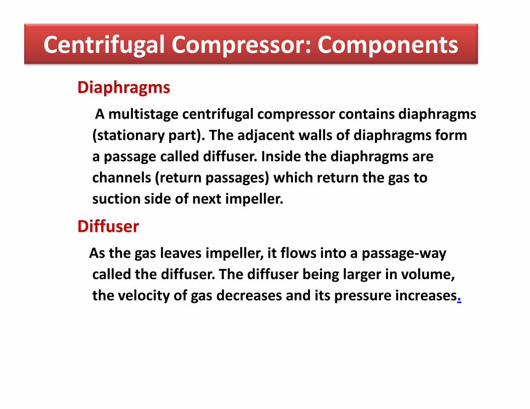
DiaphragmsA multistage centrifugal compressor contains diaphragms (stationary part). The adjacent walls of diaphragms form a passage called diffuser. Inside the diaphragms are channels (return passages) which return the gas to suction side of next impeller.
DiffuserAs the gas leaves impeller, it flows into a passage-way called the diffuser. The diffuser being larger in volume, the velocity of gas decreases and its pressure increases.
Centrifugal Compressor: Components

BearingsBearings are used to support the shaft with a minimum of friction. Bearings permit shaft to rotate freely, but they prevent axial and radial motion.
Journal Bearingsused to prevent radial motion. Hence provides Dampening action to avoid vibration of shaft.
Thrust Bearingsit is installed at the shaft end and it supports the residual axial thrust. These have number of thrust segments or shoes on each side of the collar. The thrust of rotating element is transmitted through thrust collar to the shoes, by the shoes to shoe supporting elements and then to the stationary housing & foundation.
Balancing DrumWhen axial thrust is too great for thrust bearing, then it is balanced by a
balance drum fitted on the end of shaft adjacent to the last stage impeller
Centrifugal Compressor: Components

• Axial thrust is generated inside compressor along the entire length of rotor. It is caused mainly by pressures acting against impellers.
• The pressure distribution across impeller generates a force normally in the direction of suction. The total value of this axial force depends on pressure levels and surface area of impeller upon which these pressures act.
• To compensate axial load, thrust bearing has been included in design of all compressors. Additionally, balancing drum is provided. This balancing drum is placed after last impeller of rotor, at discharge end of impeller.
• One side of balance drum is exposed to discharge pressure, while the other side is exposed to suction pressure through a balancing line connected to suction side.
• Diameter of balance drum is designed to produce a thrust from suction to discharge side of compressor. This reduces load coming from impellers that is placed upon thrust bearing.
Axial Thrust in Compressor

Centrifugal Compressor: Components

• Gas enters into the compressor through suction nozzle. Guide Vanes at inlet reduces gas turbulence and prevents recirculation of the gas.
• Gas is then drawn into eye of impeller and is discharged radially at a higher temperature and velocity from tip of impeller.
• Impeller contains blades that convert mechanical energy of the shaft into gas velocity.
• The high velocity gas flows from impeller into stationary components i.e. diffuser where part of gas velocity is reduced and is converted into pressure of the gas.
• Following the diffuser is a return channel that brings the gas to the eye of next impeller.
• Upon leaving last diffuser, gas is directed toward discharge nozzle.
• Discharge section contains Guide vanes that reduce gas turbulence and directs the gas towards the Discharge Nozzle.
Working of Centrifugal Compressor

• As the pressure is increased, the molecular resistance to the reduction in distance between molecules causes the temperature to increase. The final result is an incremental increase in gas energy.
• In a centrifugal compressor, energy in the form of torque is applied to a rotating shaft. Attached to the shaft are impellers that convert this mechanical energy into an increase in energy of gas.
• The increased energy in a gas is defined by the characteristics of pressure, temperature and velocity. These three characteristics are used to determine a quantity known as enthalpy.
Conversion of Energies in Compressor

• One compressor discharges into suction of the other
• Also referred to as compound compression
• Often used when the compression ratio of a single compressor system exceeds 10:1
• Often used in low-temperature commercial and industrial storage applications
Multistage Centrifugal Compressor

• Advantages– Discharge flow is relatively free of pulsation. – Mechanical design permits high throughputs, capacity limitation is
rarely a problem. – Centrifugal Compressors are capable of efficient performance over a
wide range of pressure and capacities even at constant speed operation.
– They are compact, less site area– They need lower maintainance requirements– They are tolerant to liquid carry– These are relatively small, occupy less space, operate with minimum
attention and quieter. – Less contamination due to lubricants.
Centrifugal Compressor

• Disadvantages– They have lower capacity
– Less efficient for small volumes.
– Discharge pressure limitation.
– Effect of gas density and temperature.
– Problem of surge phenomenon.
Centrifugal Compressor


![12-3-4-Lect-Memoria [Salvato automaticamente]](https://img.pdfslide.tips/doc/110x75/62b944bbca595f5bc33493c4/12-3-4-lect-memoria-salvato-automaticamente.jpg)