Embed Size (px)
Citation preview
Feasibility of strengthening glulam beams with prestressed basalt fibre reinforced polymers Master of Science Thesis in the Master’s Programme Structural Engineering and Building Performance Design
ZACHARY CHRISTIAN KAVAN SHEBLI
Department of Civil and Environmental Engineering Division of Structural Engineering Steel and Timber Structures CHALMERS UNIVERSITY OF TECHNOLOGY Göteborg, Sweden 2012 Master’s Thesis 2012:90

MASTER’S THESIS 2012:90
Feasibility of strengthening glulam beams with prestressed basalt fibre reinforced polymers
Master of Science Thesis in the Master’s Programme Structural Engineering and Building Performance Design
ZACHARY CHRISTIAN
KAVAN SHEBLI
Department of Civil and Environmental Engineering Division of Structural Engineering
Steel and Timber Structures
CHALMERS UNIVERSITY OF TECHNOLOGY Göteborg, Sweden 2012
Feasibility of strengthening glulam beams with prestressed basalt fibre reinforced polymers
Master of Science Thesis in the Master’s Programme Structural Engineering and Building Performance Design
ZACHARY CHRISTIAN
KAVAN SHEBLI
© ZACHARY CHRISTIAN, KAVAN SHEBLI, 2012
Examensarbete/Institutionen för bygg- och miljöteknik, Chalmers tekniska högskola2012:90 Department of Civil and Environmental Engineering Division of Structural Engineering
Steel and Timber Structures
Chalmers University of Technology
SE-412 96 Göteborg Sweden Telephone: + 46 (0)31-772 1000 Cover: Left: 10mm x 10mm BFRP mesh (Smarter Building Solutions, USA); Right: 120 mm wide BFRP fabric (TEXBAS, Poland) Chalmers Reproservice / Department of Civil and Environmental Engineering Göteborg, Sweden 2012
CHALMERS Civil and Environmental Engineering, Master’s Thesis 2012:90 I
Feasibility of strengthening glulam beams with prestressed basalt fibre reinforced polymers Master of Science Thesis in the Master’s Programme Structural Engineering and Building Performance Design
ZACHARY CHRISTIAN KAVAN SHEBLI Department of Civil and Environmental Engineering Division of Structural Engineering Steel and Timber Structures Chalmers University of Technology
Abstract With the relatively recent emergence of basalt fibre reinforced polymer products (BFRPs), the previously prohibitive issues to the introduction of FRP products to strengthen glulam beams initially seem to be addressed. The current thesis is a pilot study of the feasibility of prestressing glulam beams with BFRP materials. The principal issues facing the introduction of prestressed BFRP products in glulam beams are addressed and analysed through laboratory testing, finite element analysis and a theoretical analysis. From the observations and results of these investigations, possible production methods are considered in order to attempt to develop a plausible manufacturing technique.
The aim of the laboratory testing and FE modelling was to examine the BFRP-adhesive-wood connection with various BFRP product and adhesive combinations. The expected results were: ultimate strength, failure mode and slippage of the connection. Unfortunately, no usable results could be obtained from laboratory tests due to premature failure of the BFRP materials. The FE results show that out of all of the tested arrangements, the most appropriate was the fabric BFRP with PUR adhesive. However, the shear strength of the connection still proved to be fairly low, highlighting the need for a complicated variable prestressing solution with several small steps. Based on current knowledge and technology, it was hypothesized that the most reasonable solution to actual production of glulam beams prestressed with BFRP products would best be performed with a variable radiation curing and prestressing system. Because this system is not currently developed, large investments and investigations would be presumably needed, and it is questionable whether potential benefits from such a product would outweigh the initial efforts to develop and implement an appropriate production system.
Though the results from a theoretical analysis prove that potential for glulam beam height reduction is great, it is obvious from the work of the present thesis that a large number of challenges still exist before glulam beams prestressed with BFRP products is feasible.
Key words: prestressed glulam beams, basalt fibre reinforced polymers (BFRP), anchorage length of FRPs in glulam, delamination of FRPs in glulam, prestressed glulam production, variable prestressing

II CHALMERS Civil and Environmental Engineering, Master’s Thesis 2012:90

CHALMERS Civil and Environmental Engineering, Master’s Thesis 2012:90 III
Contents
Abstract ....................................................................................................................................... I
Preface ....................................................................................................................................... V
Nomenclature ........................................................................................................................... VI
1 Introduction ......................................................................................................................... 1
1.1 Background .................................................................................................................. 1
1.2 Objectives .................................................................................................................... 3
1.3 Methodology ................................................................................................................ 4
1.4 Limitations ................................................................................................................... 4
2 Introduction to materials ..................................................................................................... 6
2.1 Glulam ......................................................................................................................... 6
2.1.1 Benefits of using glulam ...................................................................................... 6
2.1.2 Manufacturing process ......................................................................................... 7
2.1.3 Fast curing of glulam beams .............................................................................. 11
2.2 Basalt ......................................................................................................................... 11
2.3.1 Melamine-urea-formaldehyde (MUF) ................................................................ 15
2.3.2 Polyurethane (PUR) ........................................................................................... 17
2.3.3 Epoxy ................................................................................................................. 19
3 Introduction to prestressing in composite members ......................................................... 20
3.1 History of prestressing ............................................................................................... 20
3.2 Prestressed FRPs in structural members .................................................................... 20
3.2.1 Unreinforced beam ............................................................................................. 21
3.2.2 Prestressed beam ................................................................................................ 24
3.3 Considerations with FRP attachment ........................................................................ 27
3.3.1 Basics of step-wise prestressing ......................................................................... 28
3.4 Previous studies ......................................................................................................... 29
3.4.1 Pre-cambering .................................................................................................... 29
3.4.2 Pre-tensioning ..................................................................................................... 30
3.4.3 Variable pre-tensioning ...................................................................................... 30
4 Investigations .................................................................................................................... 32
4.1 Laboratory tests ......................................................................................................... 32
4.1.1 Objectives ........................................................................................................... 32
IV CHALMERS Civil and Environmental Engineering, Master’s Thesis 2012:90
4.1.2 Materials and methods ....................................................................................... 32
4.1.3 Test configuration .............................................................................................. 34
4.1.4 Test procedure .................................................................................................... 37
4.1.5 Results and observations .................................................................................... 38
4.1.6 Conclusions ........................................................................................................ 44
4.2 FE analysis of anchorage ........................................................................................... 47
4.2.1 Objectives ........................................................................................................... 47
4.2.2 FE models ........................................................................................................... 47
4.2.3 Overall results and conclusions .......................................................................... 61
4.3 Case-study, Moelven ................................................................................................. 62
4.3.1 Objectives ........................................................................................................... 62
4.3.2 Materials ............................................................................................................. 63
4.3.3 Loads .................................................................................................................. 64
4.3.4 Methodology ...................................................................................................... 64
4.3.5 Graphic user interface ........................................................................................ 67
4.3.6 Results and conclusions ..................................................................................... 70
5 Application of investigative results .................................................................................. 72
5.1 Overall conclusions from investigations ................................................................... 72
5.2 Proposed prestressing methods .................................................................................. 73
5.2.1 Precambering ...................................................................................................... 73
5.2.2 Slippage between clamps during curing ............................................................. 75
5.2.3 Variable radiation curing .................................................................................... 76
6 Conclusions ....................................................................................................................... 80
6.1 Concluding remarks ................................................................................................... 80
6.2 Recommendations for further research ...................................................................... 82
7 References ......................................................................................................................... 83
Appendix A: Case-study, unreinforced beam design .............................................................. 86
Appendix B: Matlab code for case-study ................................................................................ 90

CHALMERS Civil and Environmental Engineering, Master’s Thesis 2012:90 V
Preface
The following Master’s thesis analyses the feasibility of prestressing glulam beams with basalt fibre reinforced polymer products (BFRPs). The work was carried out between January 2012 to July 2012 at the Division of Structural Engineering within the Department of Civil and Environmental Engineering at Chalmers University of Technology.
This thesis would not have been possible without the help and support of several people. First and foremost, we would like to thank our Examiner, Professor Robert Kliger for his time and effort in guiding our work and for providing his invaluable insight.
Our sincere thanks go to our Advisor, Dr. Reza Haghani. His constant help and guidance was key to the completion of this thesis.
Furthermore, our sincere thanks to Mohsen Heshmati for sharing his valuable Abaqus knowledge, Professor Mohammad Al-Emrani for his help during testing, and Julia Folkesson and Sandra Watkinson for their efforts as our opponents.
Finally, we would like to thank our families and significant others’ for their continued love and support.
Göteborg, July 2012
Zachary Christian
Kavan Shebli

VI CHALMERS Civil and Environmental Engineering, Master’s Thesis 2012:90
Nomenclature
E Modulus of Elasticity
E1 Modulus of Elasticity in longitudinal direction
E2 Modulus of Elasticity in transversal direction
E3 Modulus of Elasticity in radial direction
Modulus of Elasticity of Glulam beam
Modulus of Elasticity of FRP
ν Poisson’s ratio
Nu12 Poisson’s ratio in longitudinal direction
Nu13 Poisson’s ratio in transversal direction
Nu23 Poisson’s ratio in radial direction
G12 Shear Modulus in longitudinal direction
G13 Shear Modulus in transversal direction
G23 Shear Modulus in radial direction
Shear capacity
Rolling shear capacity
Width of the beam
Height of the beam
Cross-section area
Cross-section area of Glulam beam
Cross-section area of compressive rectangular zone for the glulam beam
Cross-section area of compressive triangular zone for the glulam beam
Cross-section area of tensile zone for the glulam beam
, Cross-section area FRP
Tensile force required for yielding
, Tensile capacity of glulam beam
. Force from compressive rectangular zone for the glulam
. Force from compressive triangular zone for the glulam
. Force from tensile zone for the glulam

CHALMERS Civil and Environmental Engineering, Master’s Thesis 2012:90 VII
, Force from tensile zone for the reinforcement
Pre-stressing force
Strain in compression side
Strain in tension side
, Maximum compressive elastic strain in glulam
, Maximum tensile elastic strain in glulam
, Tensile strain in the FRP
The strain due to the pre-stressing force
Height of the plasticising
Height of neutral axis in plastic phase
Navier’s lever arm from centre of gravity
Neutral axis of Glulam beam in tension side
, Neutral axis of FRP
Neutral axis of Glulam beam in compression side
Lever arm from the pre-stressed reinforcement
Moment of inertia
Moment capacity

VIII CHALMERS Civil and Environmental Engineering, Master’s Thesis 2012:90
CHALMERS Civil and Environmental Engineering, Master’s Thesis 2012:90 1
1 Introduction
Fibre reinforced polymers (FRPs) have become increasingly more studied and utilized in the reinforcement and prestressing of structural members. However, most of the FRP materials to date have at least some type of inherent drawback which prevents them from becoming more widely utilized for structural applications. FRPs composed primarily of carbon (CFRP) for instance, demonstrate exceptional structural characteristics such as high Elastic Modulus and relatively good tensile strength. However, their performance under fire testing is less than desirable and its cost is prohibitive to its use in most applications. Another common FPR is fiberglass (GFRP). GFRPs exhibit good mechanical characteristics, but again serviceability concerns and cost (though considerably less than CFRPs) make it somewhat prohibitive in its implementation in real-world applications.
The relatively new development of an FRP composed of fibres of melted basalt rock (basalt fibre reinforced polymers, BFRP) is beginning to create excitement within the construction industry as a viable FRP alternative to CFRPs and GFRPs. Basalt is naturally occurring and is one of the most abundant materials on Earth. Though early investigations were performed in the United States in the 1920s about production methods for an FRP composed of basalt, successful and large scale production was not achieved until the 1980s in what was then the Soviet Union. Up until 1995, production methods were kept secret, and its use was solely for militaristic purposes. Within the past two decades however, BFRP research and production methods have been declassified, and are now produced for civilian purposes with mechanical properties similar to those of GFRPs or CFRPs, but with generally better serviceability characteristics and at a significantly lower cost.
Currently, there are two promising applications of BFRPs within the construction industry. The first is replacement of steel reinforcement in concrete members, thereby eliminating the risk and design complications associated with the corrosion of steel. The second application, and of greater interest to the following thesis, is its use as prestressing in engineered wood products such as glulam beams. Previously, prestressing of wood products with FRP materials was considered cost prohibitive. Additionally, concerns were raised about response of other FRPs during fire loading. However, based on the reported characteristics of basalt FRPs, not only would mechanical properties similar to previous FRPs be achieved, but concerns related to response during fire would be eliminated due to basalt’s extremely high thermal resistance.
1.1 Background The benefits of prestressing engineered wood products, and more specifically glulam, are great. Often in simply-supported glulam beams, the determining factor in design is deflection criteria. Therefore, a reduction in deflection due to prestressing can potentially reduce the beam cross section height – reducing material usage and necessary floor or building height.
2 CHALMERS Civil and Environmental Engineering, Master’s Thesis 2012:90
Furthermore, the allowable design strength of timber is limited by its high variability with regard to mechanical properties. Through gluing of timber into products such as glulam, variability is to some extent reduced simply by the inclusion of several different timber pieces. Further reduction can be achieved by the addition of a more standardized, man-made material such as an FRP due to greater control during production, obtaining less variability with increasing structural responsibility of the FRP in the member. Therefore, not only does prestressing greatly improve the response in serviceability, but it also further homogenizes a particularly variable product such as timber. The task, however, has been to find a cost effective material which not only exhibits the mechanical properties necessary to provide an ample prestressing force, but also performs well in serviceability situations such as fire loading. According to previous research and data provided about current Basalt Fibre Reinforced Polymers, an appropriate BFRP product should achieve this goal.
In prestressing of structural members, prestressing calculations can either be performed by considering full interaction between the prestressing member and the structural member, or by considering partial or no interaction between the members – such as if the prestressing member were enclosed in a tube. However, for purposes of more efficiently integrating the prestressing material into glulam production, full interaction is desired so that it acts essentially as an additional lamella, thereby creating what is referred to as a composite member. When considering composite structural members (those whose cross section is composed of two or more materials), one of the main concerns is adhesive strength between the two materials. The adhesive strength determines which sections along the beam may or may not be considered to act according to classic beam theory as described by linear elastic beam theory. The adhesion between the two materials also determines the anchorage length of the prestressing material, which is the length required for full interaction between the prestressing material and primary beam material. At this point along the beam, all of the prestressing force has been transferred to the section from the prestressing material, and the section can be accurately described according to linear elastic beam theory. Accordingly, the interaction between the adhesive, prestressing material and structural material are of great interest. Therefore, in order to obtain better interaction and additionally to protect the adhesive which connects the BFRP to the glulam from possible fire damage, the BFRP is considered here to be embedded at a distance of one lamella away from the tensile edge under service loading.
An additional concern to be considered in the prestressing of glulam beams is the inherent material properties of the glulam itself. One of the greatest challenges when attempting to introduce a prestressed material into a timber product is its relatively low “rolling shear” strength. Rolling shear is the case in which both shear components are perpendicular to the grain. Therefore, when considering a force acting axially such as prestressing, the force must be limited in some way in order to not exceed the rolling shear capacity of the glulam. One method of achieving this while still being able to attain the benefits of a high prestressing force is through variable prestressing. In such a case, the prestressing force is increased step-wise from zero at the ends of the beam to a maximum force towards the middle of the beam, where each step should be equal to or greater than a distance twice that of the anchorage
CHALMERS Civil and Environmental Engineering, Master’s Thesis 2012:90 3
length to assure that full interaction is achieved across each step and prevent the accumulation of stresses between steps.
1.2 Objectives The aim of the current thesis is to determine the feasibility of strengthening glulam beams with prestressed BFRP products. This will be achieved through investigating the following in order to address the previously described concerns:
Adhesives:
The effect of choice of different types of commonly used adhesives and their effectiveness in adhering to BFRP products will be studied. Three main adhesives will be considered – polyurethane (PUR), melamine-urea-formaldehyde (MUF) and a mixed-use structural epoxy.
BFRP product type/arrangement:
Two different types of BFRP products will be examined and compared. One is a strip of BFRP fabric, while the second is a fish-net style mesh, with thicker BFRP strands in the longitudinal direction.
Current glulam production methods:
Current glulam production methods will be explained and analysed in order to attempt to develop a prestressing method that most suitably corresponds to current manufacturing methods of unreinforced glulam beams, thereby saving extra labour and machine costs.
Possible manufacturing methods:
In order to determine possible efficient production methods for introduction of prestressed BFRP products in glulam beams.
Strength limitations of materials and connections
4 CHALMERS Civil and Environmental Engineering, Master’s Thesis 2012:90
1.3 Methodology
The previously described objectives will be obtained by means of four separate investigations.
Experimental testing of anchorage length and slip of adhesive joints:
Physical test specimens will be manufactured which will then be tested through loading. Results of the testing will be collected and analysed in order to attempt determine connection strength, anchorage length and slippage between materials for different proposed material and product combinations.
FE analysis of anchorage lengths through use of the commercial software, Abaqus CAE:
A finite element analysis will be performed on models which attempt to simulate the experimental testing. Results will be utilized to compare with experimental results; thereby mutually confirming experimental and FE models in addition to allowing for a more detailed analysis of connection behaviour than solely from experimental results.
Case-study in order to determine potential benefits:
A computer program will be developed which theoretically determines the possible savings of a prestressed glulam beam with BFRP versus a glulam beam designed with no prestressing. Through use of the developed program, a previously designed glulam beam will be reanalysed to determine possible benefits from the introduction of prestressed BFRP products.
Development of proposed manufacturing methods:
Based on the results of previous studies, efficient manufacturing methods for the introduction of prestressed BFRP in glulam beams will be proposed and briefly analysed through rough FE analysis and calculations.
1.4 Limitations
Limitations to the current study are as follow:
The study primarily examines the case of a simply-supported prestressed beam.

CHALMERS Civil and Environmental Engineering, Master’s Thesis 2012:90 5
Creep of the timber is considered only in the developed computer program, and as a modification factor applied when time is equal to infinity.
Possible relaxation of the BFRP material is not considered.
Only two possible BFRP products were studied – a fabric and a net-like mesh, and only two different adhesives are considered for each of these products (PUR and Epoxy in the fabric, and MUF and PUR in the mesh).
6 CHALMERS Civil and Environmental Engineering, Master’s Thesis 2012:90
2 Introduction to materials
2.1 Glulam
Glulam is an engineered timber product which was first developed in Germany in the end of 19th century, and became in use in Scandinavian countries beginning in the 20th century. In Sweden, the first glulam was manufactured in 1919 in Töreboda. Glulam is manufactured from wood laminations bonded together with adhesive, parallel to the longitudinal grain direction. The thickness of the lamellae depends on the design and stress range. In Sweden, for regular straight applications the thickness of each lamella is typically 45 mm. For curved applications, however, the thickness can depend on the radius of curvature. Glulam beams are manufactured with the strongest lamellae in the outer edges of the beam, where the compression and tension stresses are maximal. This allows lumber with different grades to be used more efficiently by placing higher graded lumbers in zones with higher stress and lower graded lumbers in lower stress zones.
2.1.1 Benefits of using glulam The benefits of using glulam beams as opposed to other more ”conventional” construction materials are many, and are outlined in the following (Engineered Wood Systems – APA EWS 2000):
Strength: Glulam is one of the strongest structural materials per unit weight, compared with steel or concrete.
Environment concerns: The raw material is renewable. Laminated timber can be reused or recycled.
Aesthetics: The choice of glulam allows the design of a building and its structural members to suit the function and use those structural members without protection or cladding.
Energy saving: Energy consumption during glulam manufacturing is much lower compared to other materials.
Corrosion resistance: Glued laminated timber can withstand aggressive environments better than many other construction materials and will never corrode due to high resistance to chemical attack and aggressive environments.
Dimensional stability: Glulam neither twists nor curls as opposed to non-engineered wood products.
Superior fire resistance: Glulam has a high and predictable resistance to fire.
CHALMERS Civil and Environmental Engineering, Master’s Thesis 2012:90 7
Price: Total cost of a glulam structure is often lower than other materials.
Large spans: Glulam can be used for large span constructions of up to 50 meters. The limitations are commonly governmental restrictions on transportation to construction site.
2.1.2 Manufacturing process
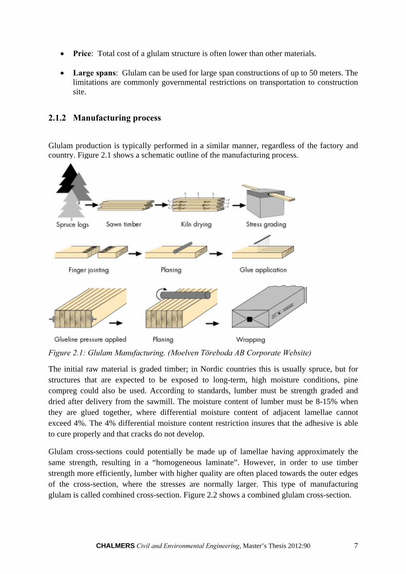
Glulam production is typically performed in a similar manner, regardless of the factory and country. Figure 2.1 shows a schematic outline of the manufacturing process.
Figure 2.1: Glulam Manufacturing. (Moelven Töreboda AB Corporate Website)
The initial raw material is graded timber; in Nordic countries this is usually spruce, but for structures that are expected to be exposed to long-term, high moisture conditions, pine compreg could also be used. According to standards, lumber must be strength graded and dried after delivery from the sawmill. The moisture content of lumber must be 8-15% when they are glued together, where differential moisture content of adjacent lamellae cannot exceed 4%. The 4% differential moisture content restriction insures that the adhesive is able to cure properly and that cracks do not develop.
Glulam cross-sections could potentially be made up of lamellae having approximately the same strength, resulting in a “homogeneous laminate”. However, in order to use timber strength more efficiently, lumber with higher quality are often placed towards the outer edges of the cross-section, where the stresses are normally larger. This type of manufacturing glulam is called combined cross-section. Figure 2.2 shows a combined glulam cross-section.
8 CHALMERS Civil and Environmental Engineering, Master’s Thesis 2012:90
Figure 2.2: Lay-up of Homogeneous Glulam and Combined Glulam (Moelven et al.)
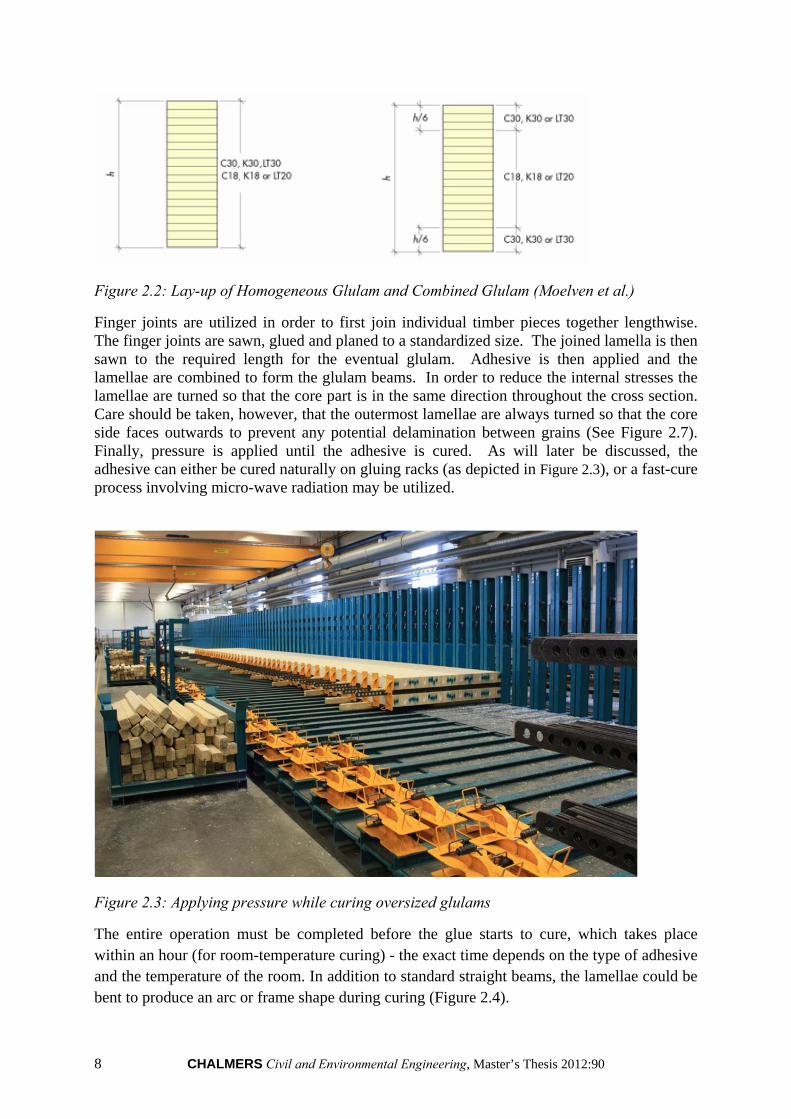
Finger joints are utilized in order to first join individual timber pieces together lengthwise. The finger joints are sawn, glued and planed to a standardized size. The joined lamella is then sawn to the required length for the eventual glulam. Adhesive is then applied and the lamellae are combined to form the glulam beams. In order to reduce the internal stresses the lamellae are turned so that the core part is in the same direction throughout the cross section. Care should be taken, however, that the outermost lamellae are always turned so that the core side faces outwards to prevent any potential delamination between grains (See Figure 2.7). Finally, pressure is applied until the adhesive is cured. As will later be discussed, the adhesive can either be cured naturally on gluing racks (as depicted in Figure 2.3), or a fast-cure process involving micro-wave radiation may be utilized.
Figure 2.3: Applying pressure while curing oversized glulams
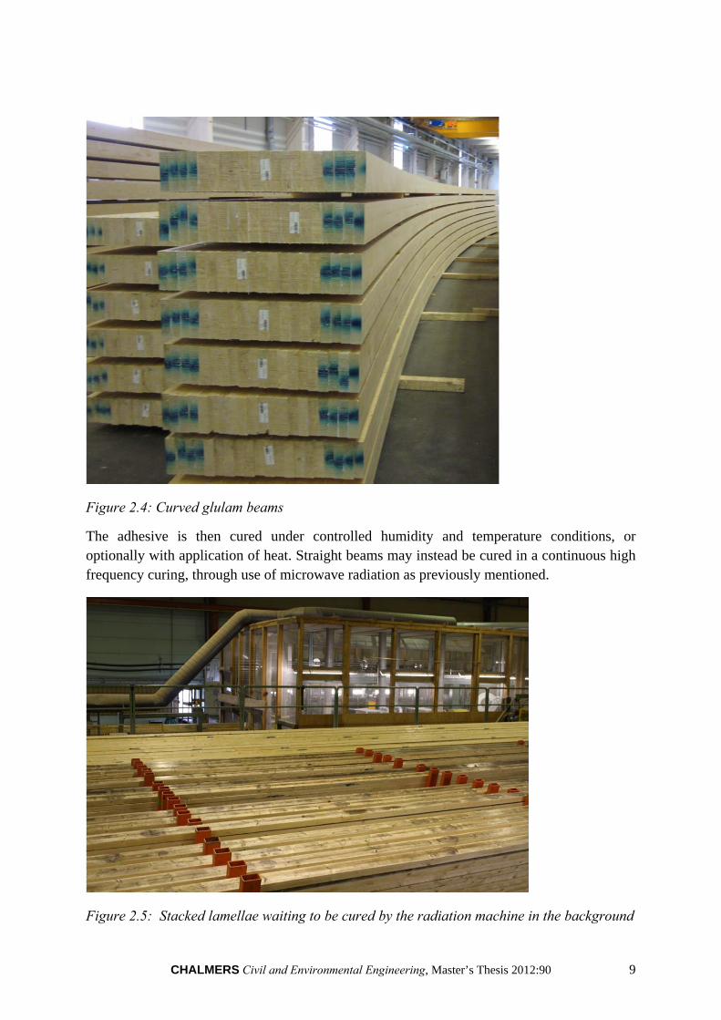
The entire operation must be completed before the glue starts to cure, which takes place within an hour (for room-temperature curing) - the exact time depends on the type of adhesive and the temperature of the room. In addition to standard straight beams, the lamellae could be bent to produce an arc or frame shape during curing (Figure 2.4).
CHALMERS Civil and Environmental Engineering, Master’s Thesis 2012:90 9
Figure 2.4: Curved glulam beams
The adhesive is then cured under controlled humidity and temperature conditions, or optionally with application of heat. Straight beams may instead be cured in a continuous high frequency curing, through use of microwave radiation as previously mentioned.
Figure 2.5: Stacked lamellae waiting to be cured by the radiation machine in the background
10 CHALMERS Civil and Environmental Engineering, Master’s Thesis 2012:90
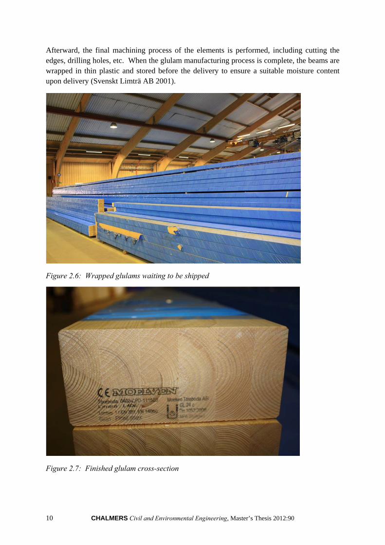
Afterward, the final machining process of the elements is performed, including cutting the edges, drilling holes, etc. When the glulam manufacturing process is complete, the beams are wrapped in thin plastic and stored before the delivery to ensure a suitable moisture content upon delivery (Svenskt Limträ AB 2001).
Figure 2.6: Wrapped glulams waiting to be shipped
Figure 2.7: Finished glulam cross-section
CHALMERS Civil and Environmental Engineering, Master’s Thesis 2012:90 11
2.1.3 Fast curing of glulam beams
There are generally two ways for fast curing glulam beams; radio frequencies (RF) and microwave frequencies (µW). The first method (RF) involves the application of radio frequencies to heat the beam which consequently cures the adhesive. Radio frequencies for fast curing of glulam beams has been investigated and tested in wood industry but it has not yet been properly understood or used. The second method (µW) involves the application of microwave frequencies to pre-heat the beam and thus cure the glue. When the glued lamellae enter the microwave, molecules in the adhesive which are initially already polar start to vibrate and consequently heat up, polymerize and bond to the wood. The water molecules in the glue will also heat up due to the effects of the microwave radiation; however this is not the main process which facilitates adhesion. Microwave radiation, in contrast to radio frequencies, has been developed further and has become a standard commercial product in the wood industry. Moelven in Töreboda, Sweden for instance, which was visited as part of the investigations of the present master’s thesis, is currently using microwave radiation technology. However, this production method is currently limited to standard glulam beams, and additional types of beams such as those which are oversized or curved must be cured instead using the previously mentioned curing racks at room temperature (Testa 2012).
2.2 Basalt
Basalt is a naturally occurring material, produced from the solidification of volcanic lava. It is composed primarily of SiO2, and is the most abundant rock found in the Earth’s crust. Russia has nearly endless reserves, though with only 30 active quarries. Other countries with volcanic areas also contain basalt reserves – the United States for instance has thousands of square kilometres of easily accessible basalt in places such as Washington, Oregon and Idaho (Parnas et al. 2007). However, as chemical content differs by location, one of the greatest challenges of use of basalt materials is a relatively high variation in mechanical properties.
In order to produce a usable form of basalt, fibres are extruded and spun from molten basalt rock at temperatures of between 1300-1700°C, with diameters generally of 13 to 20 µm (Patnaik 2009, Parnas et al. 2007). Later, the basalt fibres are then normally combined with a resin polymer to form the final desired product – basalt fibre reinforced polymers (BFRPs).
Mechanical properties of the basalt fibres depend on the circumstances during formation in addition to variation in chemical content. Generally, however, the material properties of interest can be assumed as follow:
12 CHALMERS Civil and Environmental Engineering, Master’s Thesis 2012:90
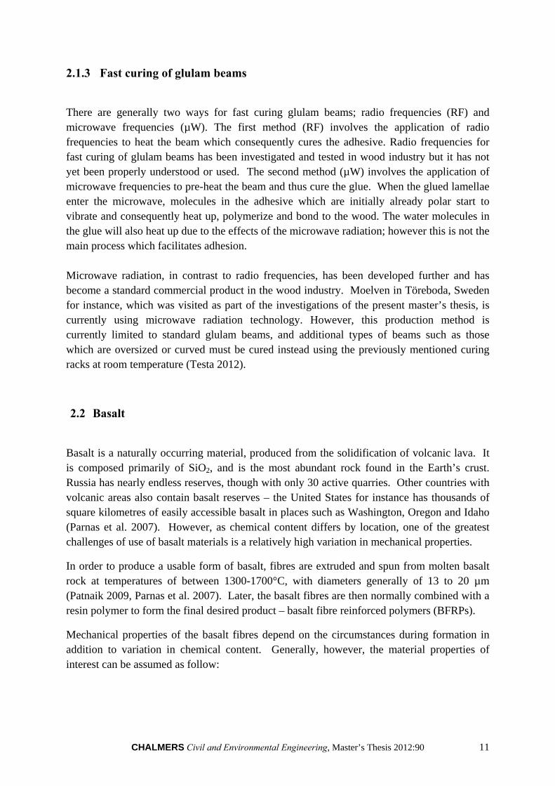
Table 2.1: FRP Properties
(unit) Basalt (a) Fiberglass (a) Carbon (b) Density g/cm3 2.75 2.6 1.75-1.95 Thermal Expansion Coefficient
ppm/°C 8.0 5.4 (-0.1)-(-1.6)
(c) Tensile Strength MPa 4840 3450 2500-6000 Elastic Modulus GPa 89 77 200-800 Maximum Application Temperature
°C 982 650 500 (d)
(a): (Smarter Building Systems 2010), (b): (Carolin 2003), (c): (Adhikari 2009), (d): (Chowdhury et al. 2007)
In the Table 2.1, the mechanical characteristics of basalt are compared to those of other common FRPs. As can be seen, basalt presents characteristics similar to those of fiberglass, but with much higher resistance to fire due to its high thermal coefficient - an important consideration in timber structures. An even greater difference can be seen in performance at high temperatures between basalt and carbon FRPs, with the average temperature of fire reaching well above the temperature at which mechanical properties of carbon are affected. Therefore, any possible benefit achieved from the higher modulus of elasticity of carbon as opposed to the more brittle basalt, must be carefully weighed against risks associated with fire response.
Because basalt fibre’s Elastic Modulus is less than half that of typical reinforcement materials such as steel or carbon FRPs, it is generally assumed here that any benefits of introduction of basalt merely as reinforcement (without prestressing) would have little to modest improvements. Therefore, in the current thesis only pretensioning of basalt is considered in order to strengthen glulam beams.
Additional properties of interest for use in the construction industry are basalt’s high resistance to alkalis and acids which eliminates the risk of corrosion as is the case of steel (most notably steel rebar cast in concrete).
With regard to environmental and health concerns, basalt is a “sustainable” product in that it comes from natural sources. Additionally, it is free from carcinogens and other health hazards, posing no risk to humans or nature (Adhikari 2009).
FRP products in general are not a new phenomenon. Fiberglass, carbon and aramid FRPs have been used for decades in various industries with great success. Within the construction industry, FRPs have shown great potential but have generally proven to be cost-restrictive, especially in the case of timber structures. However, basalt seems to overcome previous restrictions in that it not only demonstrates strength characteristics similar to the other FRPs, but does so at a much lower cost.
In the current project, two types of Basalt FRPs are investigated. It was initially hypothesized that a “net-like arrangement” (hereby known as the “mesh BFRP”) would allow for easier incorporation of a prestressed BFRP product in typical glulam production. It was assumed
CHALMERS Civil and Environmental Engineering, Master’s Thesis 2012:90 13
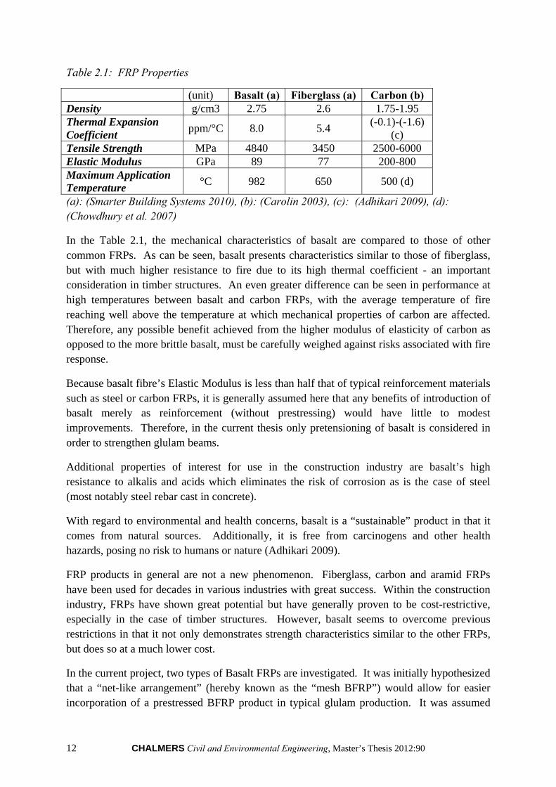
that a connection strength similar to that of a timber-to-timber connection could be obtained, while employing commonly utilized timber-to-timber adhesives, through timber-to-timber connection at the voids in the material. The material examined in the current thesis is the 10mm x 10mm Basalt mesh from Smarter Building Systems in Rhode Island, USA. The product specific material data is depicted in Figure 2.8 as provided by said company. It should be noted that Figure 2.7 depicts solely the strength characteristics per basalt fibre, while the following are more product specific results. Therefore as can be seen in the difference in strength characteristics, due to the presence of resin, the strength of the basalt fibre cannot be directly taken as the tensile strength of basalt fibres by the cross-sectional area of the strand by number of strands. As it became clear during testing, the actual proportion of basalt fibres to resin is relatively low. It should also be noted from the provided testing results that there is a relatively high standard deviation of ultimate strength.
Table 2.2: Tensile strength tests of mesh BFRP (Smarter et al. 2010)
Sample Maximum Load [N]
1 2725,71 2 2720,00 3 2685,71 4 2885,71 5 2811.43
Average 2765.71 Standard Deviation 81.52
Sample size: 25 mm x 25 mm
Figure 2.8: Mesh BFRP
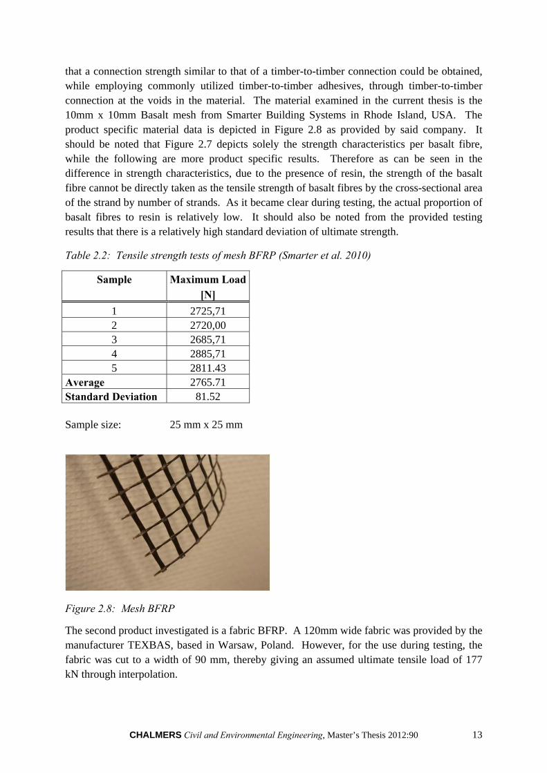
The second product investigated is a fabric BFRP. A 120mm wide fabric was provided by the manufacturer TEXBAS, based in Warsaw, Poland. However, for the use during testing, the fabric was cut to a width of 90 mm, thereby giving an assumed ultimate tensile load of 177 kN through interpolation.
14 CHALMERS Civil and Environmental Engineering, Master’s Thesis 2012:90
Table 2.3: Fabric BFRP product information (TEXBAS TM 2012)
Size Thickness Width Number of strands Ultimate Load [mm x mm] [mm] [mm] per width [kN]
0.4 x 15 0.4 + 0.025 15 +/- 1 32 +/- 2 29 0.4 x 17 0.4 + 0.025 17 +/- 1 36 +/- 2 33 0.4 x 25 0.4 + 0.025 25 +/- 1 66 +/- 2 49 0.4 x 50 0.4 + 0.025 50 +/- 1 132 +/- 2 98 0.4 x 55 0.4 + 0.025 55 +/- 1 145 +/- 2 108
0.4 x 120 0.4 + 0.025 120 +/- 1 187 +/- 2 237
Figure 2.9: Fabric BFRP
With regard to long-term mechanical characteristics, no specific values could be found. However, it is stated by several sources that creep and shrinkage of the BFRP can be taken as negligible due to its material properties.
2.3 Adhesives
”Adhesion refers to the interaction of the adhesive surface with the substrate surface.” (Frihart 2005). Generally, there are three main steps involved in the process of adhesive bonding (Frihart 2005):
Preparation of the surfaces to be adhered: in order to provide optimal interaction between adhesive and surface
Contact of adhesive with surfaces: wetting and penetration
Setting: solidification and or curing of the adhesive
Possibly the most important considerations when investigating adhesion are the wetting and penetration characteristics between the adhesive and material, especially for water-borne adhesives such as Melamine-urea-formaldehyde (MUF). Wetting is controlled by several factors, most notably the relative surface energies of the adhesive and substrate. Adhesives
CHALMERS Civil and Environmental Engineering, Master’s Thesis 2012:90 15
with high surface tensions (due to being water-borne) have difficulty properly wetting substrates with low surface energy. Other adhesion considerations which affect the bonding, such as flow and penetration of the adhesive into the substrate material, are also dependent upon surface energies. For these reasons, FRPs with low surface energies generally are difficult to adhere using wood adhesives with high surface energies. Epoxies on the other hand do not rely on surface tensions and are therefore considered more of a multi-purpose adhesive.
Even though wood bonding is one of the oldest adhesive applications, wood is still one of the most complicated materials to bond due to its inherent material properties which greatly influence adhesive interaction and the wetting process. The anisotropic nature of wood due to the elongation of cells in the longitudinal direction in addition to difference between radial and tangential properties causes difficulties when trying to predict adhesion behaviour.
As has been previously mentioned, two different BFRP configurations are to be tested. One, a fabric-like product, allows for no wood-to-wood bonding and therefore requires more multi-purpose adhesives. Thus, two common multi-purpose adhesives [epoxy and polyurethane (PUR)] have been chosen to be tested in conjunction with this BFRP product. The second BFRP product is that of a mesh-like arrangement with large voids, allowing for wood-to-wood contact. It was hypothesized initially that by maintaining wood-to-wood contact, the BFRP would be able to be more easily introduced to current manufacturing processes. Thus, for this configuration, the most common purely wood-to-wood adhesive was chosen (MUF) in addition to the stronger PUR used as a control. The adhesives investigated and their corresponding mechanical properties of interest are summarized in Table 2.4.
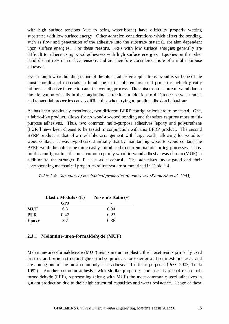
Table 2.4: Summary of mechanical properties of adhesives (Konnerth et al. 2005)
Elastic Modulus (E) Poisson's Ratio (ν) GPa -
MUF 6.3 0.34 PUR 0.47 0.23 Epoxy 3.2 0.36
2.3.1 Melamine-urea-formaldehyde (MUF)
Melamine-urea-formaldehyde (MUF) resins are aminoplastic thermoset resins primarily used in structural or non-structural glued timber products for exterior and semi-exterior uses, and are among one of the most commonly used adhesives for these purposes (Pizzi 2003, Trada 1992). Another common adhesive with similar properties and uses is phenol-resorcinol-formaldehyde (PRF), representing (along with MUF) the most commonly used adhesives in glulam production due to their high structural capacities and water resistance. Usage of these
16 CHALMERS Civil and Environmental Engineering, Master’s Thesis 2012:90
adhesives has limitations, however, when bonded with non-wood products due to being water-borne.
MUF is white when cured, and is almost invisible from longer distances. Therefore, a glulam beam utilized as a ceiling support would appear as a continuous wood product. In stark contrast, PRF is nearly black when cured, accenting the connections between laminates even from a far distance. Due to this aesthetic difference, architects and builders have requested MUF over PRF so frequently that many glulam manufacturers such as Moelven use almost exclusively MUF in glulam production.
Specifications for Use:
In use with timber products, the product specifications as provided by Akzo Nobel for Melamine-urea Adhesive 1247 (Hardener 2526) are as follows during application:
Temperature range for mixing: 17-25°C
Temperature of wood during application: above 20°C
Recommended moisture content of wood during application: 10-12%
Plane wood surface before application
Specifications during curing are as follows:
Temperature above 20°C
Application of Pressure of at least 0.8 MPa
Pressing time of at least 5.75 hours for 100:20 (adhesive : hardener) mix at 20°C
Upon proper application and curing of MUF, the following mechanical properties of interest are developed.
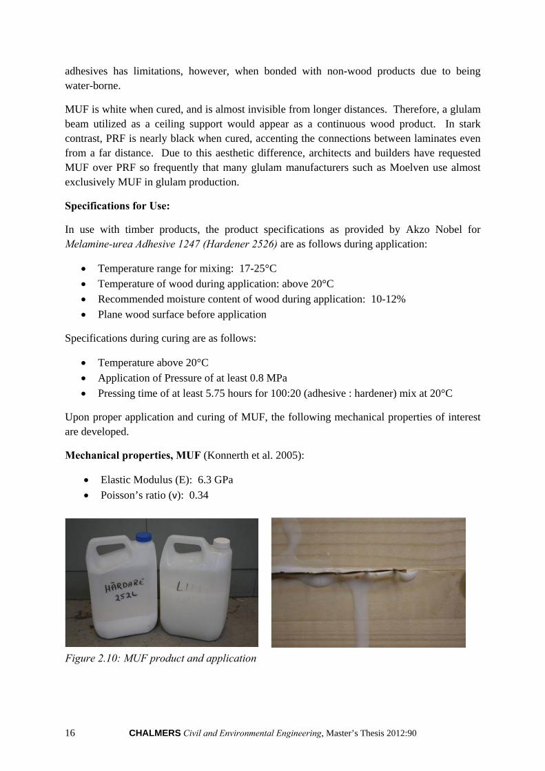
Mechanical properties, MUF (Konnerth et al. 2005):
Elastic Modulus (E): 6.3 GPa
Poisson’s ratio (ν): 0.34
Figure 2.10: MUF product and application
CHALMERS Civil and Environmental Engineering, Master’s Thesis 2012:90 17
2.3.2 Polyurethane (PUR)
Polyurethane adhesive was produced in the early 1930s at Bayer in Germany. Polyurethane adhesives are normally defined as those adhesives that contain a number of urethane groups in the molecular backbone or are formed during use, regardless of the chemical composition of the rest of the chain. Thus a typical urethane adhesive may contain, in addition to urethane linkages, aliphatic and aromatic hydrocarbons, esters, ethers, amides, urea and allophanate groups. (Eling et al. 2012). There are two types of polyurethanes which include:
2-component: One component is a hydroxyl compound. The second (hardener) is isocyanate. Both are solvent-free components and react with each other during the formation of polyurethane.
1-component: Consists of isocyanate. Isocyanate reacts with moisture from the
material or the air to form amine. In the reaction of carbon dioxide emitted. The amine reacts with the isocyanate to form a polyurea band with similar binding properties as polyurethane. 1-component PUR adhesive is one of the latest adhesives on the market. These adhesives can bond with most materials such as textile fibres, metals, plastics, wood, glass, ceramics, rubber and leather. They are also known for their excellent adhesion, elasticity, high cohesive strength and rapid hardening without heat. Releasing of carbon dioxide causes the glue foam to expand. If this is process is done without control (pressing time, pressing pressure, air and material humidity), the glue joint becomes too thick and the adhesive strength is reduced. 1-component polyurethane adhesive can also be used for highly relatively moist wood, up to about 20%. Moreover, one and two component polyurethane adhesive have similar characteristics.
The advantages of this solvent glue are both its processing and product character.
Processing advantages:
Curing without heat input.
More pressure capacity through shorter press times, which can provide larger flows and reduce bottlenecks in production compared to conventional adhesives.
Less adhesive consumption.
No time needed for mixing of the adhesive.
Less time for cleaning the adhesive equipment.
Less waste of adhesive.
Less sensitivity to varying moisture content of glued materials.
Higher speed during the cutting operation of final products.
Gluing can be performed with wetter wood (Collano 8-40%).
Less tool wear.
Product advantages:
Strong and weather-resistant glue joints.
18 CHALMERS Civil and Environmental Engineering, Master’s Thesis 2012:90
Light glue line.
No formaldehyde emissions
Disadvantages of using polyurethane:
Isocyanate is one of the main substances in Polyurethane, which is widely used because of its reactivity with groups that contain reactive hydrogen, such as amine and alcohol groups at room temperature. This allows high flexibility in the types of products, because they can self-polymerize or react with many other monomers. A disadvantage of using isocyanate is that isocyanate will react rapidly with water that is present in most wood products. This water can reduce the effective molecular weight by altering the stoichiometry and can compete with desired reactions with the wood, such as the hydroxyl groups in the cellulose and hemicellulose fractions as well as the phenols and hydroxyl groups in the lignin domains. But the most important disadvantage is that they can react rapidly with many compounds present in human bodies. These reactions are rapid under physiological conditions and are not readily reversible which means that safety of handling isocyanate is a concern. The concern is greatest during the manufacturing stage when low molecular weight and volatile isocyanate are still present; once these react, the resulting ureas and esters are quite safe. An exception is that the heat of combustion causes the formation of free isocyanate groups. Isocyanates used in wood bonding are not as hazardous as some other isocyanates in that they generally have higher molecular weight so their volatility and the number of free isocyanate groups are diminished. (Frihart 2005). Therefore, great care must be taken during production involving PUR adhesives.
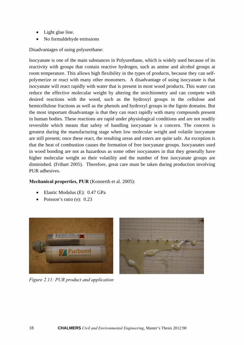
Mechanical properties, PUR (Konnerth et al. 2005):
Elastic Modulus (E): 0.47 GPa
Poisson’s ratio (ν): 0.23
Figure 2.11: PUR product and application
CHALMERS Civil and Environmental Engineering, Master’s Thesis 2012:90 19
2.3.3 Epoxy
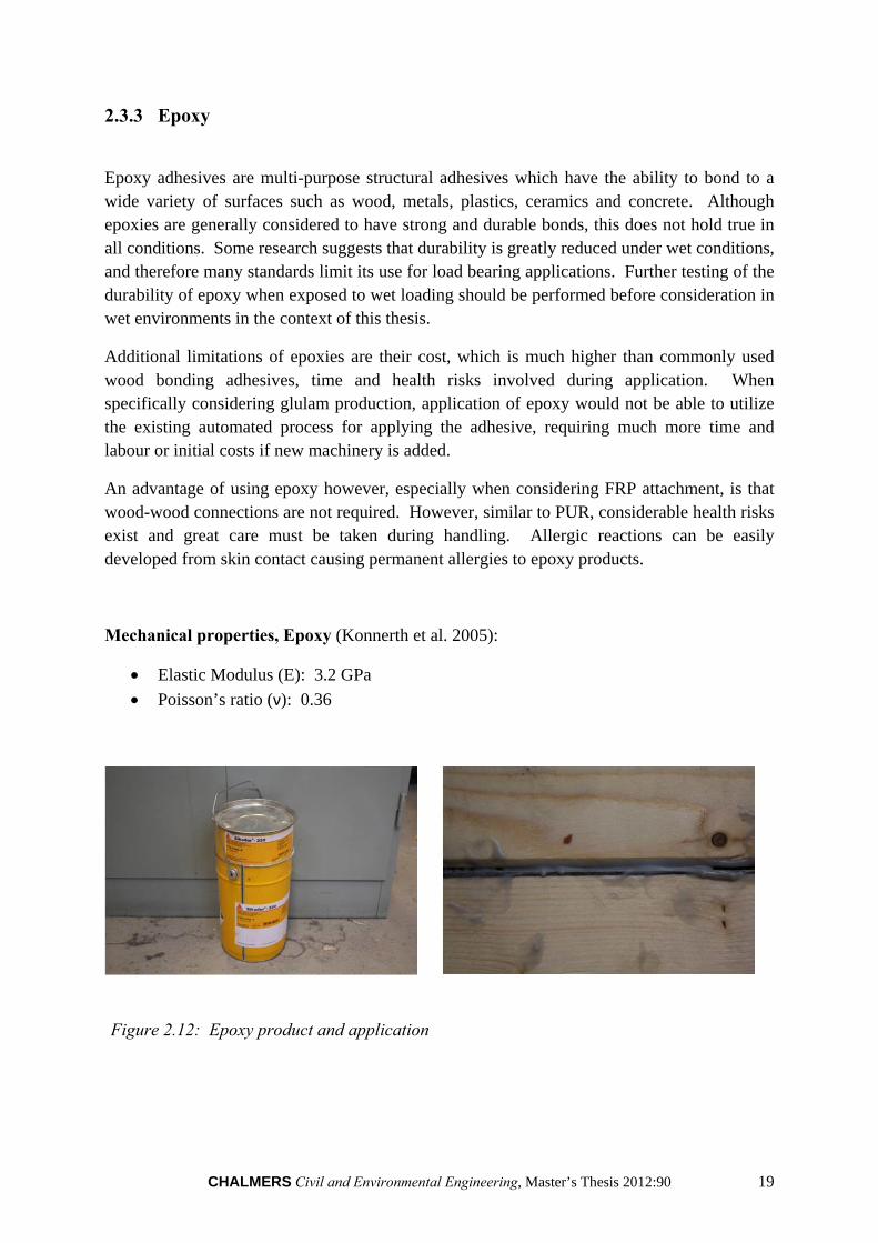
Epoxy adhesives are multi-purpose structural adhesives which have the ability to bond to a wide variety of surfaces such as wood, metals, plastics, ceramics and concrete. Although epoxies are generally considered to have strong and durable bonds, this does not hold true in all conditions. Some research suggests that durability is greatly reduced under wet conditions, and therefore many standards limit its use for load bearing applications. Further testing of the durability of epoxy when exposed to wet loading should be performed before consideration in wet environments in the context of this thesis.
Additional limitations of epoxies are their cost, which is much higher than commonly used wood bonding adhesives, time and health risks involved during application. When specifically considering glulam production, application of epoxy would not be able to utilize the existing automated process for applying the adhesive, requiring much more time and labour or initial costs if new machinery is added.
An advantage of using epoxy however, especially when considering FRP attachment, is that wood-wood connections are not required. However, similar to PUR, considerable health risks exist and great care must be taken during handling. Allergic reactions can be easily developed from skin contact causing permanent allergies to epoxy products.
Mechanical properties, Epoxy (Konnerth et al. 2005):
Elastic Modulus (E): 3.2 GPa
Poisson’s ratio (ν): 0.36
Figure 2.12: Epoxy product and application
20 CHALMERS Civil and Environmental Engineering, Master’s Thesis 2012:90
3 Introduction to prestressing in composite members
3.1 History of prestressing
The basic goal of prestressing a structure is to create a negative moment in the construction to improve its serviceability under loading (Nordin 2005). A prestressed structure can therefore be made much thinner than a structure with unprestressed reinforcement. However, since prestressing often is more costly, it is mainly used on larger structures or for structures which demands small deformations during loading.
The first attempts to prestress structural members were in concrete structures with normal strength steel in the late 1800’s to early 1900’s. However, these attempts were unsuccessful, due to low strength of normal steel at the time. In 1928 though, prestressing of concrete members became practical after Eugene Freyssinet, a French civil engineer, incorporated the use high-strength steel wires for prestressing (Collins et al. 1991). Significant development of prestressed concrete was possible after T.Y. Lin’s load-balancing method of design (Dinges 2009). Since that time, prestressing concrete members with steel has developed considerably and has become a common occurrence. More recently, new research and applications involving various different materials has been under development; most notably with prestressing components composed of fibre reinforced polymers.
3.2 Prestressed FRPs in structural members
In the recent two decades, use of FRPs for strengthening and repairing structures has increased widely due to relatively good mechanical properties such as high stiffness, high strength, good durability and light weight. The benefits of using FRP may be increased further by prestressing the FRP before bonding to the structure (Haghani 2010). Due to their increasing development and therefore benefits, strengthening of structural members with FRPs has begun to be analysed for applications with all of the major construction materials – concrete, steel and timber.
The benefits for using prestressed FRPs for concrete structures include: reduction in deformations due to live loads, increased performance of the structure in serviceability limit state, reduced crack width on the tensile part of the structure and thus increasing the durability of the members, and providing a negative moment to counteract the dead load. (Haghani 2010). With regard to steel structures reinforced with prestressed FRPs, the main advantages are: increased fatigue life of the members and prevention of fatigue crack deformation or propagation in the steel structures (Haghani 2010).
Of more interest to the current thesis, timber structural members have also been analysed for potential benefits from the addition of prestressed FRPs. Since deflection is typically the controlling design limitation in timber members, the primary benefit of using prestressed
CHALMERS Civil and Environmental Engineering, Master’s Thesis 2012:90 21
FRPs for timber structures is in decreasing the deflection in the serviceability limit state. By using prestressed FRPs in timber structures, a negative moment would be applied to the member which would enhance the resistance to live loads, thus reducing the necessary beam height under the same loads. Another benefit of prestressing timber is from a change of the failure mode from a brittle mode to a more ductile mode by decreasing the stresses in the tension side of the beam and thereby generally limiting failure to the more plastic compressive side (Balsiero et al. 2010). In this manner, if failure were to occur, it would be a longer more visually notable failure, providing ample time for repair or escape as opposed to a sudden breakage of the beam which would be the case given a more brittle tensile failure. The following explains theoretically how the aforementioned benefits from prestressing timber are achieved.
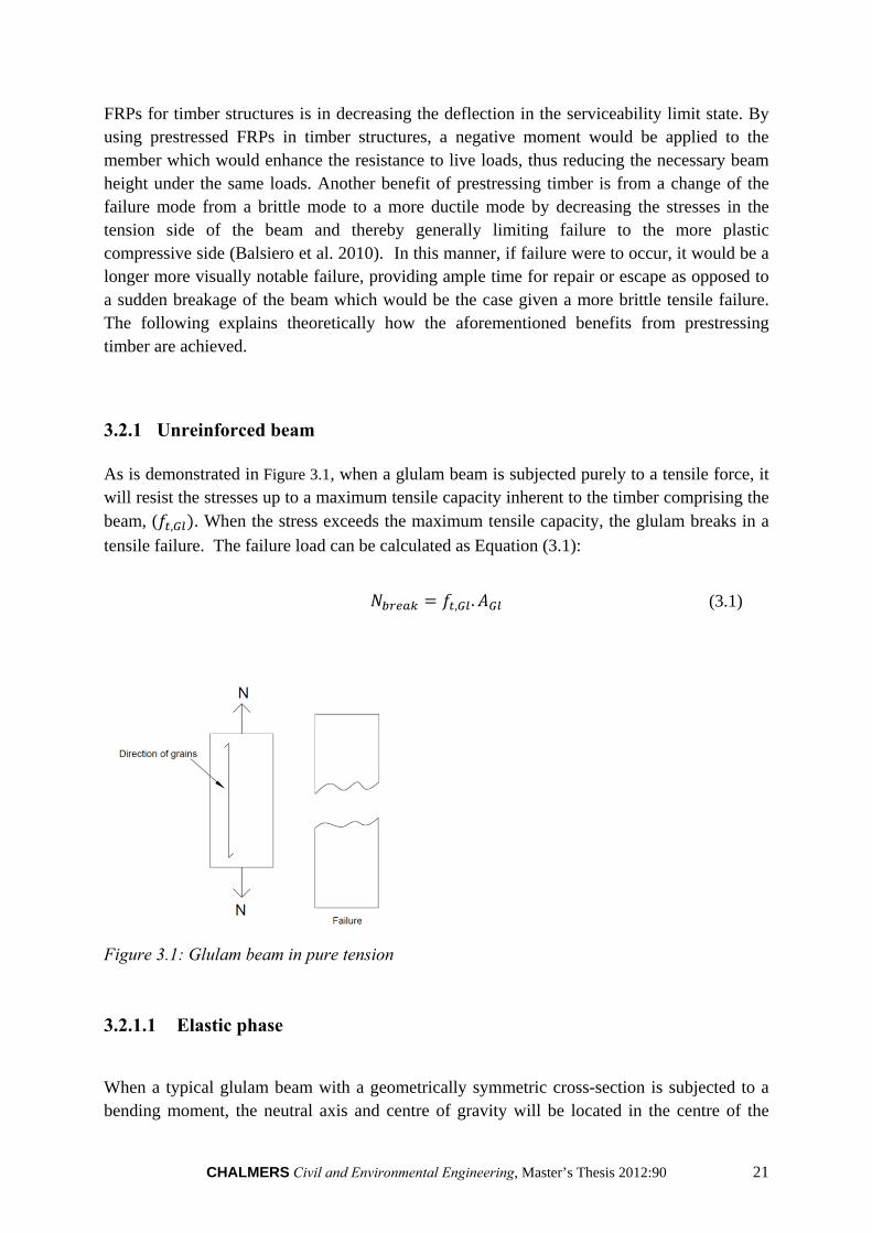
3.2.1 Unreinforced beam As is demonstrated in Figure 3.1, when a glulam beam is subjected purely to a tensile force, it will resist the stresses up to a maximum tensile capacity inherent to the timber comprising the beam, ( , . When the stress exceeds the maximum tensile capacity, the glulam breaks in a
tensile failure. The failure load can be calculated as Equation (3.1):
, . (3.1)
Figure 3.1: Glulam beam in pure tension
3.2.1.1 Elastic phase
When a typical glulam beam with a geometrically symmetric cross-section is subjected to a bending moment, the neutral axis and centre of gravity will be located in the centre of the
22 CHALMERS Civil and Environmental Engineering, Master’s Thesis 2012:90
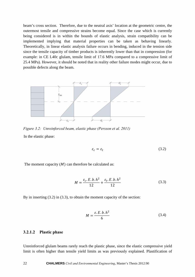
beam’s cross section. Therefore, due to the neutral axis’ location at the geometric centre, the outermost tensile and compressive strains become equal. Since the case which is currently being considered is in within the bounds of elastic analysis, strain compatibility can be implemented implying that material properties can be taken as behaving linearly. Theoretically, in linear elastic analysis failure occurs in bending, induced in the tension side since the tensile capacity of timber products is inherently lower than that in compression (for example: in CE L40c glulam, tensile limit of 17.6 MPa compared to a compressive limit of 25.4 MPa). However, it should be noted that in reality other failure modes might occur, due to possible defects along the beam.
Figure 3.2: Unreinforced beam, elastic phase (Persson et al. 2011)
In the elastic phase:
(3.2)
The moment capacity ( can therefore be calculated as:
. . .12
. . .12
(3.3)
By in inserting (3.2) in (3.3), to obtain the moment capacity of the section:
. . .6
(3.4)
3.2.1.2 Plastic phase
Unreinforced glulam beams rarely reach the plastic phase, since the elastic compressive yield limit is often higher than tensile yield limits as was previously explained. Plastification of
CHALMERS Civil and Environmental Engineering, Master’s Thesis 2012:90 23
timber may develop however if the elastic compressive yield limit is reached. Plastification occurs when strains above the elastic yield are obtained, and are redistributed within the compressive zone. The plastified section of the compressive zone increases with increasing strain. Further stresses cannot be carried during plastification and the neutral axis will therefore be shifted towards the tensile side. The strain can continue until it reaches the ultimate strain capacity and failure occurs. During the plastification phase, Navier’s formula no longer applies and therefore a strain compatibility approach must instead be employed.
It has been determined by previous research that the ultimate plastic strain in wood can be assumed as being three times the ultimate elastic strain (Edlund 1995). The existence of plasticity in compression in timber can be explained by the following phenomena (Barlow & Woodhouse 1992):
Gross buckling of cell walls
Sliding of cell layers over each other
Pulling apart of adjacent cell walls
Macroscopic buckling which causes in localized plastic hinges
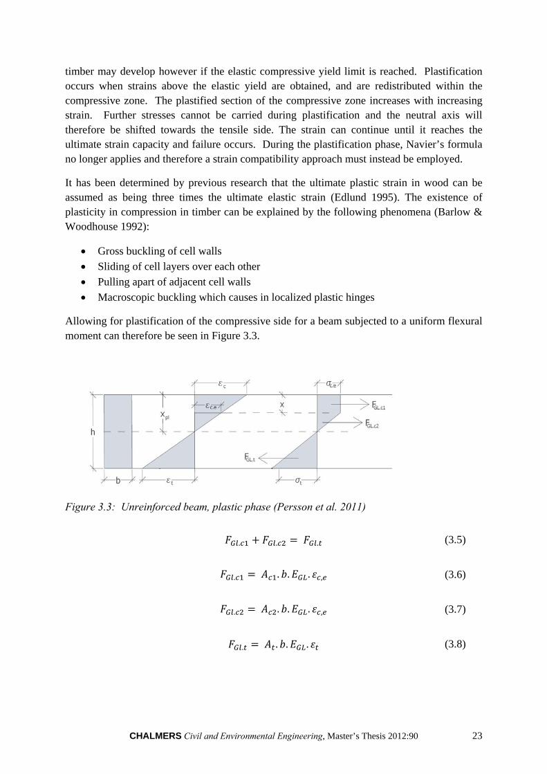
Allowing for plastification of the compressive side for a beam subjected to a uniform flexural moment can therefore be seen in Figure 3.3.
Figure 3.3: Unreinforced beam, plastic phase (Persson et al. 2011)
. . . (3.5)
. . . . , (3.6)
. . . . , (3.7)
. . . . (3.8)
24 CHALMERS Civil and Environmental Engineering, Master’s Thesis 2012:90
As previously mentioned, when a glulam starts to plasticize, the stress distribution will be limited and begin to produce a rectangular pattern due to constant stress given increasing strains above the elastic strain limit ( , . The height of the plasticized region is indicated as
" " in the figure. The new height of compressive zone is defined as" ".
The moment capacity in plasticized glulam can thus be calculated as:
. . 2
23. . .
23. . . (3.9)
Where:
, . (3.10)
. (3.11)
,. (3.12)
3.2.2 Prestressed beam
For the purposes considered in the current thesis, a prestressed glulam beam is considered with the FRP material located in the tension side, a distance of one lamella away from the outer edge. The axial prestressing force applied by the FRP material therefore will cause a negative moment in the beam after releasing the force due to eccentricity. This negative moment produces an upward cambering of the beam. The applied axial stress is limited by the tensile strength of the FRP in addition to the rolling shear in the wood. Additionally, the moment due to prestressing is also limited by the tensile and compressive strength of the glulam beam (taken here as conservative as opposed to the “bending strength” of timber).
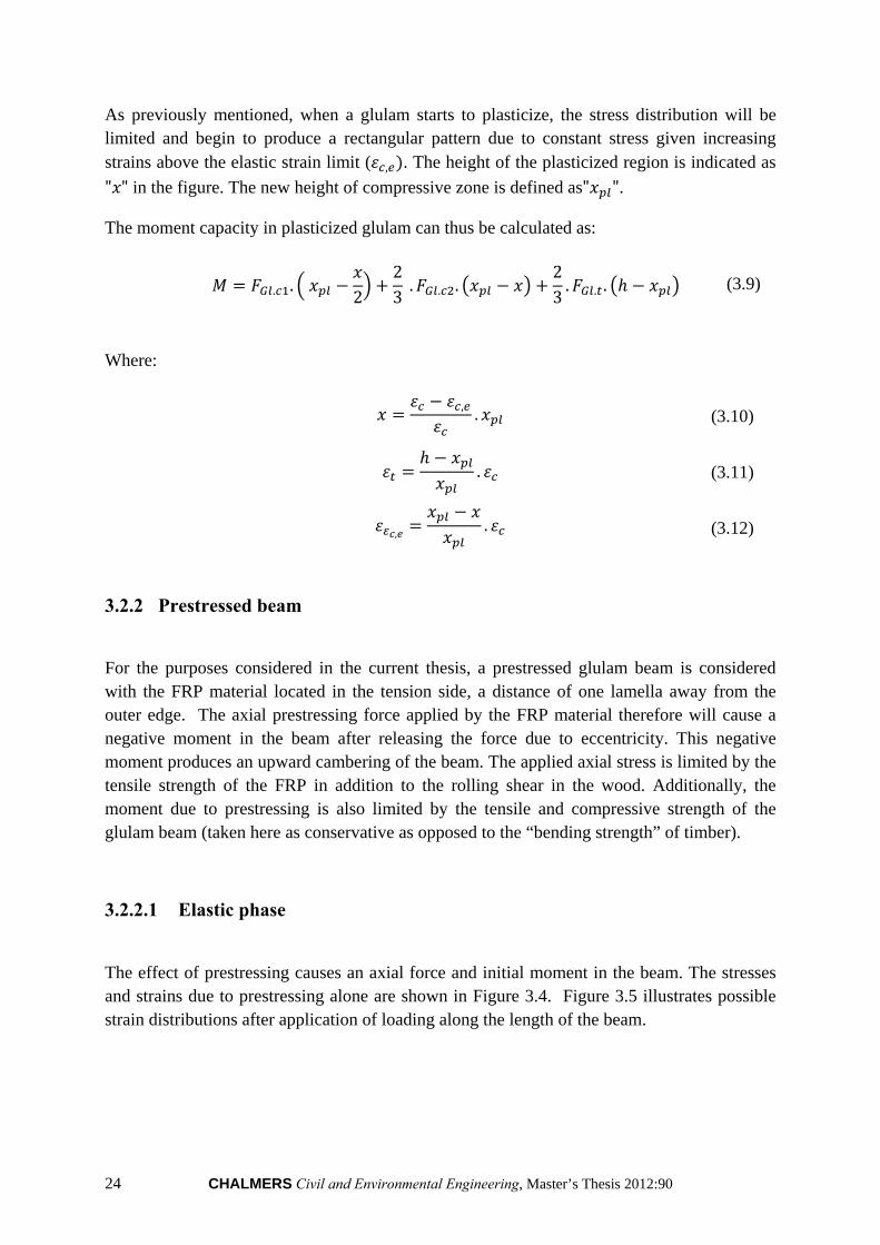
3.2.2.1 Elastic phase
The effect of prestressing causes an axial force and initial moment in the beam. The stresses and strains due to prestressing alone are shown in Figure 3.4. Figure 3.5 illustrates possible strain distributions after application of loading along the length of the beam.
CHALMERS Civil and Environmental Engineering, Master’s Thesis 2012:90 25
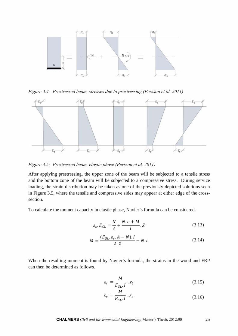
Figure 3.4: Prestressed beam, stresses due to prestressing (Persson et al. 2011)
Figure 3.5: Prestressed beam, elastic phase (Persson et al. 2011)
After applying prestressing, the upper zone of the beam will be subjected to a tensile stress and the bottom zone of the beam will be subjected to a compressive stress. During service loading, the strain distribution may be taken as one of the previously depicted solutions seen in Figure 3.5, where the tensile and compressive sides may appear at either edge of the cross-section.
To calculate the moment capacity in elastic phase, Navier’s formula can be considered.
..
. (3.13)
. . .
.. (3.14)
When the resulting moment is found by Navier’s formula, the strains in the wood and FRP can then be determined as follows.
.. (3.15)
.. (3.16)
26 CHALMERS Civil and Environmental Engineering, Master’s Thesis 2012:90
, .. , (3.17)
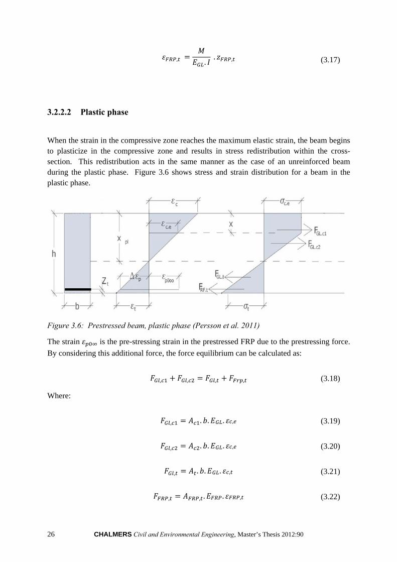
3.2.2.2 Plastic phase
When the strain in the compressive zone reaches the maximum elastic strain, the beam begins to plasticize in the compressive zone and results in stress redistribution within the cross-section. This redistribution acts in the same manner as the case of an unreinforced beam during the plastic phase. Figure 3.6 shows stress and strain distribution for a beam in the plastic phase.
Figure 3.6: Prestressed beam, plastic phase (Persson et al. 2011)
The strain is the pre-stressing strain in the prestressed FRP due to the prestressing force.
By considering this additional force, the force equilibrium can be calculated as:
, , , , (3.18)
Where:
, . . . , (3.19)
, . . . , (3.20)
, . . . , (3.21)
, , . . , (3.22)
CHALMERS Civil and Environmental Engineering, Master’s Thesis 2012:90 27
By using the equilibrium condition and considering that is always known, the height of
neutral axis in the plastic phase ( can be calculated if the strains are defined withε .
, . (3.23)
, . (3.24)
. (3.25)
, . (3.26)
When the functions above are determined, the plastic moment capacity of the section can then be found as:
. . . . . . . . , .
(3.27)
3.3 Considerations with FRP attachment
Prestressing FRP laminates for strengthening and repair of structures presents several challenges, due primarily to difficulties which can occur due to the bonding of prestressed FRPs to glulam beams. One of the greatest challenges encountered is development of high shear stresses at the ends of the prestressed FRP which can easily exceed the strength of the adhesive. Conventional adhesives used in composite structures such as epoxy resins normally withstand 20-25 MPa, whereas the shear stress at the ends can typically reach values of around 40-50 MPa. These high shear stresses in the ends of the prestressed FRP may result in delamination or debonding of the FRP laminate from the structural member (Al-Emrani et al. 2007). Another challenge more specific to prestressing glulam beams is the low rolling shear capacity in timber, which is generally taken as one third of the shear capacity of timber.
1 (3.28)
If the shear stress in bonding exceeds this limit, failure may occur due to very small prestressing loads in a timber structure. A further challenge is the potential risk of delamination. In the present master’s thesis however, for simplification purposes and lack of information we assume full interaction between adhesives and BFRP. Furthermore, the effect
28 CHALMERS Civil and Environmental Engineering, Master’s Thesis 2012:90
of the relaxation is not considered since little to no relaxation is assumed to occur in BFRP products.
The most appropriate solution to overcome these previously outlined challenges is through implementing step-wise prestressing of FRP laminate. Through this method, the desired axial force can be applied to the FRP in several steps in order to limit the shear stress development by the rolling shear capacity of the wood. The following further describes this method.
3.3.1 Basics of step-wise prestressing
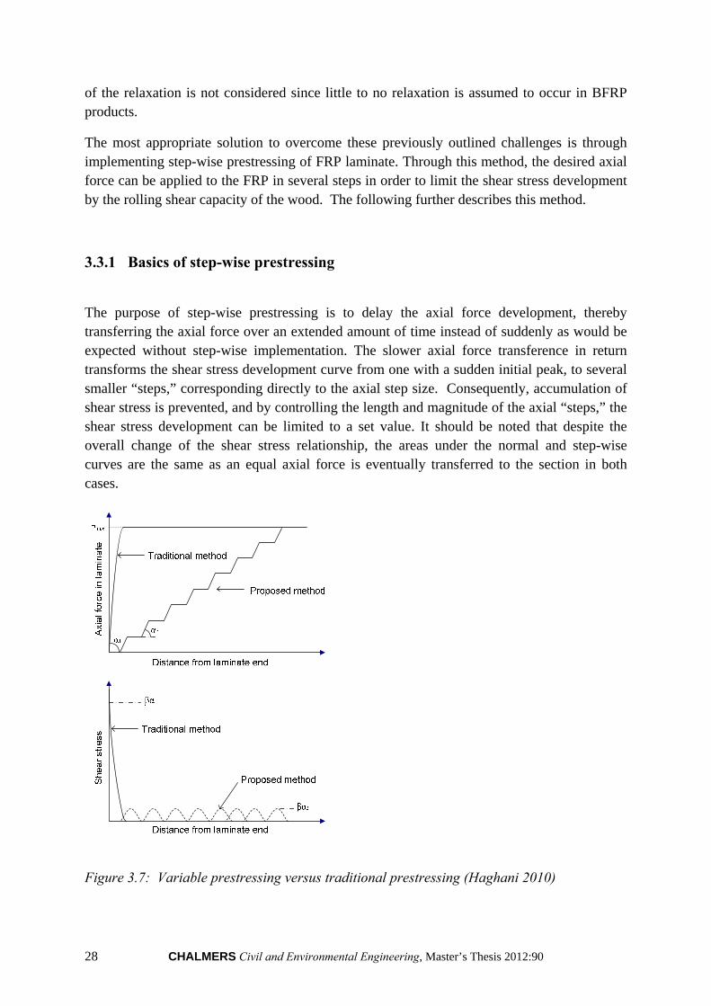
The purpose of step-wise prestressing is to delay the axial force development, thereby transferring the axial force over an extended amount of time instead of suddenly as would be expected without step-wise implementation. The slower axial force transference in return transforms the shear stress development curve from one with a sudden initial peak, to several smaller “steps,” corresponding directly to the axial step size. Consequently, accumulation of shear stress is prevented, and by controlling the length and magnitude of the axial “steps,” the shear stress development can be limited to a set value. It should be noted that despite the overall change of the shear stress relationship, the areas under the normal and step-wise curves are the same as an equal axial force is eventually transferred to the section in both cases.
Figure 3.7: Variable prestressing versus traditional prestressing (Haghani 2010)
CHALMERS Civil and Environmental Engineering, Master’s Thesis 2012:90 29
Through implementation of this method, the application of the axial force can be controlled by the rolling shear capacity of the wood and length of the steps, which can be determined by the anchorage length determined for the traditional method.
In order to achieve the previously described results, the anchorage length must first be defined. Through previous research, it was found that the anchorage length can be reasonably considered as the point along the non-variably prestressed curve which corresponds to 1% of the maximum shear stress at the edge. The “step-size” can then be found as twice this length, so as to avoid cumulative effects along the stress development curve. Additionally, the allowable axial load per step can then be found by determining the load which produces a stress peak within the defined limits for a case of non-variably applied axial force (Haghani 2010).
3.4 Previous studies
Several methods to prestress glulam beams with FRPs have been investigated in recent decades. These investigations are summarized below:
3.4.1 Pre-cambering
One method of prestressing of introducing a prestressed FRP has been the “indirect” method of pre-cambering, in which a beam is initially pre-cambered, the FRP is adhered and then the cambering released in order to pre-tension the FRP. In one study (Balsiero et al. 2010) adhered CFRP (Carbon fibre reinforced polymer) to a pre-cambered beam by cambering the beam to its maximum curvature limit and then bonding a non-tensioned CFRP product to the bottom face of a glulam beam. The cambering procedure is not very complicated and requires very light equipment. The following results were noted:
Low increase in strength due to small percentage of reinforcements causes a small change in the strength.
Small degree of cambering and curvature should be imposed to the beam to not damage the beam during cambering. The result was the stress in the FRP caused by cambering was very low.
Another study (El-Hachal et al. 2001) strengthened an existing concrete bridge by means of a prestressed FRP through use of a cambering effect. A vertical load was applied on two points under the beam with hydraulic jacks to produce the camber. Then FRP was placed under the concrete beam. After curing the adhesive the jacks were removed and the FRP was released. The observations were as follows:
A low level of prestress could be induced to the beam after releasing the jacks.
30 CHALMERS Civil and Environmental Engineering, Master’s Thesis 2012:90
“Inefficient use of material and could damage and overstress the strengthened beam.”
Thus, as can be seen by the previous research, pre-cambering risks damage to the beam while producing minimal improvements both in the case of strengthening a new beam as well as in situations involving pre-existing construction.
3.4.2 Pre-tensioning
A second method of prestressing a glulam beam is through direct application of a pretensioned FRP member. One group of investigators (Dolan et al. 2012) tested glulam beams with the addition of Kevlar FRPs in both as pure un-tensioned reinforcement as well as a prestressed member in order to analyse the benefits of prestressing the glulam. The Kevlar FRP was placed between the two outermost lamellae. The results of interest were those of the flexural strength tests as well as the shear tests of the connections. With respect to the flexural strength tests, the results did not agree well with the expected results, with premature failure which the authors attributed to inherent defects in the glulam. From the shear tests of the connections, it was noted that with increasing prestress of the Kevlar FRP, a decrease in shear strength occurred. Additionally, it can be seen that relatively high standard deviation exists in the data, suggesting unreliable results.
Another group (Guan et al. 2005) placed a prestressed GFRP a distance of 1 lamella from the tensile edge of a glulam beam and subjected to a bending force. Only FE models are analysed – no experimental tests were performed. Additionally, it should be noted that the allowable shear stress was limited by the average shear strength of the timber considered, instead of the rolling shear. A similar study was conducted by another team of investigators (Brady et al. 2012); however in this instance only theoretical calculations were performed – no experimental testing or FEM analysis.
As is demonstrated by the previous work, an increase in bending capacity is plausible due to the introduction of prestressed FRP products in glulam beams. However, due to the limited scope of the studies and what are considered here to be inaccurate assumptions (most specifically the choice of average strength over the rolling shear to limit the prestressing force), no real conclusions beyond its plausibility can safely be made.
3.4.3 Variable pre-tensioning
A third prestressing method of glulam beams involves the more challenging technique of achieving variable prestressing. However, despite the challenges, as it is seen during the present thesis, the results are more appropriate when prestressing glulam beams. In one study (Davids et al. 2010, Strengthening…) developed a technique of achieving variable prestressing through the release of the prestressing force on the FRP after clamping but before
CHALMERS Civil and Environmental Engineering, Master’s Thesis 2012:90 31
the adhesive was cured. Thus, the friction produced from the clamping forces allowed for a more gradual transfer of the prestressing force from the FRP to the section. A 95% strength improvement in bending was noted over unreinforced beams and no delamination or anchorage failures were observed.
In a second study (Brunner et al. 2005); variable prestressing was achieved through use of an anchoring device with the addition of alternative curing of the adhesive by heating. In this manner, no delamination was noted for prestressing forces of up to 60 kN, and currently further investigations are being performed at higher forces.
Though the previous studies demonstrate promising results, it should also be noted that both techniques present unique challenges. In the first, where variable prestressing is achieved by release of the prestressing force during curing, predicting the actual results is extremely complicated. A model must be developed which accurately takes into account the frictional forces between all of the materials and the rate of curing of the adhesives. The second method presents more predictable results. However, due to the considerable time required during heat-curing of adhesives, the additional adhesive not intended to be cured during the initial steps would have already begun curing by the time that curing should theoretically begin in those steps.
32 CHALMERS Civil and Environmental Engineering, Master’s Thesis 2012:90
4 Investigations
In the following section, the three primary investigations undertaken in the current thesis are outline and discussed. The investigations are as follows:
Laboratory Tests
FE Analysis of Anchorage
Case-Study and Optimization Program Development
The results from the three investigations are studied and the overall knowledge gained is applied in the Section 5 where possible production methods are analysed.
4.1 Laboratory tests
4.1.1 Objectives
In the laboratory testing, specimens are made and tested in order to:
Determine the experimental anchorage length of several different adhesive and BFRP configurations.
Determine the failure modes of the connections.
Determine the ultimate strength of the connections.
Determine the slippage of the connection, if any.
4.1.2 Materials and methods
Specimens were cut from previously tested, but structurally sound, CE L40c Glulam beams. For ease of sample construction, lamellae of the same size as those in the existing Glulam beams were chosen. Therefore, the sample cross section will be taken as 45 mm high by 90 mm wide. It should be noted that in order to maintain the 45 mm height, samples were cut where the previous adhesive line lies in the middle of the new “lamellae.” In this manner, samples can still be cut at 45 mm while not having to consider removal of the adhesive. Additionally, a sample length of 300 mm is chosen in order to provide enough length for BFRP attachment as well as to prevent crushing of the timber in compression at the support. All specimens were examined for defects in the wood prior to gluing, and unacceptable specimens were discarded. Therefore, the specimens tested are free from compression wood, large knots, or other defects.
CHALMERS Civil and Environmental Engineering, Master’s Thesis 2012:90 33
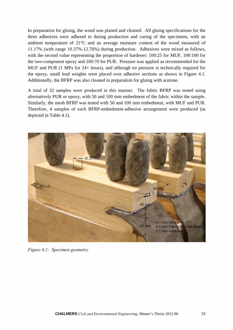
In preparation for gluing, the wood was planed and cleaned. All gluing specifications for the three adhesives were adhered to during production and curing of the specimens, with an ambient temperature of 21°C and an average moisture content of the wood measured of 11.17% (with range 10.37%-12.76%) during production. Adhesives were mixed as follows, with the second value representing the proportion of hardener: 100:25 for MUF, 100:100 for the two-component epoxy and 100:70 for PUR. Pressure was applied as recommended for the MUF and PUR (1 MPa for 24+ hours), and although no pressure is technically required for the epoxy, small lead weights were placed over adhesive sections as shown in Figure 4.1. Additionally, the BFRP was also cleaned in preparation for gluing with acetone.
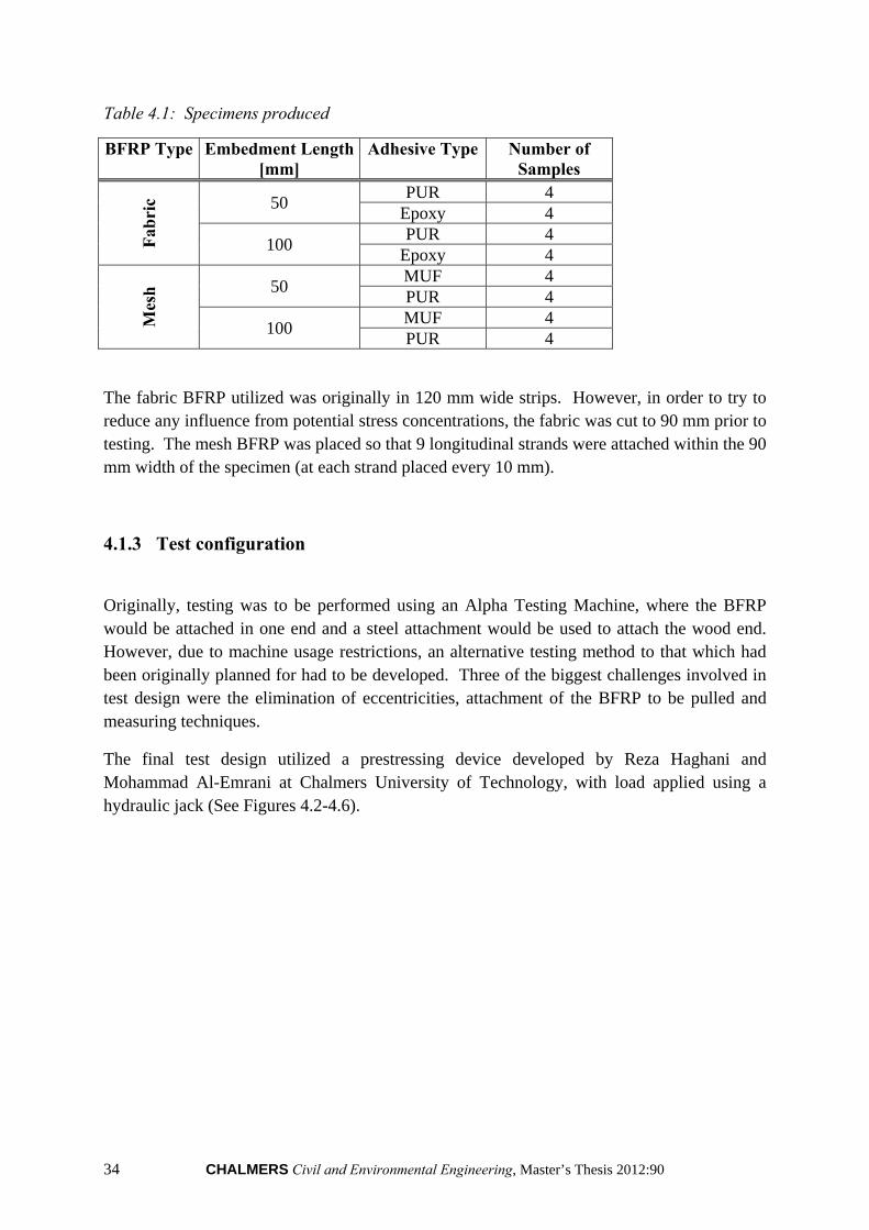
A total of 32 samples were produced in this manner. The fabric BFRP was tested using alternatively PUR or epoxy, with 50 and 100 mm embedment of the fabric within the sample. Similarly, the mesh BFRP was tested with 50 and 100 mm embedment, with MUF and PUR. Therefore, 4 samples of each BFRP-embedment-adhesive arrangement were produced (as depicted in Table 4.1).
Figure 4.1: Specimen geometry
34 CHALMERS Civil and Environmental Engineering, Master’s Thesis 2012:90
Table 4.1: Specimens produced
BFRP Type Embedment Length Adhesive Type Number of [mm] Samples
Fab
ric 50
PUR 4 Epoxy 4
100 PUR 4
Epoxy 4
Mes
h 50
MUF 4 PUR 4
100 MUF 4 PUR 4
The fabric BFRP utilized was originally in 120 mm wide strips. However, in order to try to reduce any influence from potential stress concentrations, the fabric was cut to 90 mm prior to testing. The mesh BFRP was placed so that 9 longitudinal strands were attached within the 90 mm width of the specimen (at each strand placed every 10 mm).
4.1.3 Test configuration
Originally, testing was to be performed using an Alpha Testing Machine, where the BFRP would be attached in one end and a steel attachment would be used to attach the wood end. However, due to machine usage restrictions, an alternative testing method to that which had been originally planned for had to be developed. Three of the biggest challenges involved in test design were the elimination of eccentricities, attachment of the BFRP to be pulled and measuring techniques.
The final test design utilized a prestressing device developed by Reza Haghani and Mohammad Al-Emrani at Chalmers University of Technology, with load applied using a hydraulic jack (See Figures 4.2-4.6).
CHALMERS Civil and Environmental Engineering, Master’s Thesis 2012:90 35
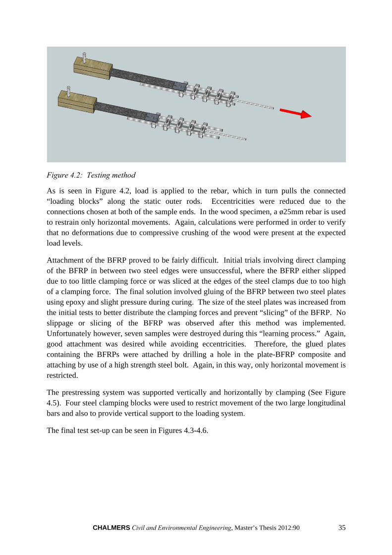
Figure 4.2: Testing method
As is seen in Figure 4.2, load is applied to the rebar, which in turn pulls the connected “loading blocks” along the static outer rods. Eccentricities were reduced due to the connections chosen at both of the sample ends. In the wood specimen, a ø25mm rebar is used to restrain only horizontal movements. Again, calculations were performed in order to verify that no deformations due to compressive crushing of the wood were present at the expected load levels.
Attachment of the BFRP proved to be fairly difficult. Initial trials involving direct clamping of the BFRP in between two steel edges were unsuccessful, where the BFRP either slipped due to too little clamping force or was sliced at the edges of the steel clamps due to too high of a clamping force. The final solution involved gluing of the BFRP between two steel plates using epoxy and slight pressure during curing. The size of the steel plates was increased from the initial tests to better distribute the clamping forces and prevent “slicing” of the BFRP. No slippage or slicing of the BFRP was observed after this method was implemented. Unfortunately however, seven samples were destroyed during this “learning process.” Again, good attachment was desired while avoiding eccentricities. Therefore, the glued plates containing the BFRPs were attached by drilling a hole in the plate-BFRP composite and attaching by use of a high strength steel bolt. Again, in this way, only horizontal movement is restricted.
The prestressing system was supported vertically and horizontally by clamping (See Figure 4.5). Four steel clamping blocks were used to restrict movement of the two large longitudinal bars and also to provide vertical support to the loading system.
The final test set-up can be seen in Figures 4.3-4.6.
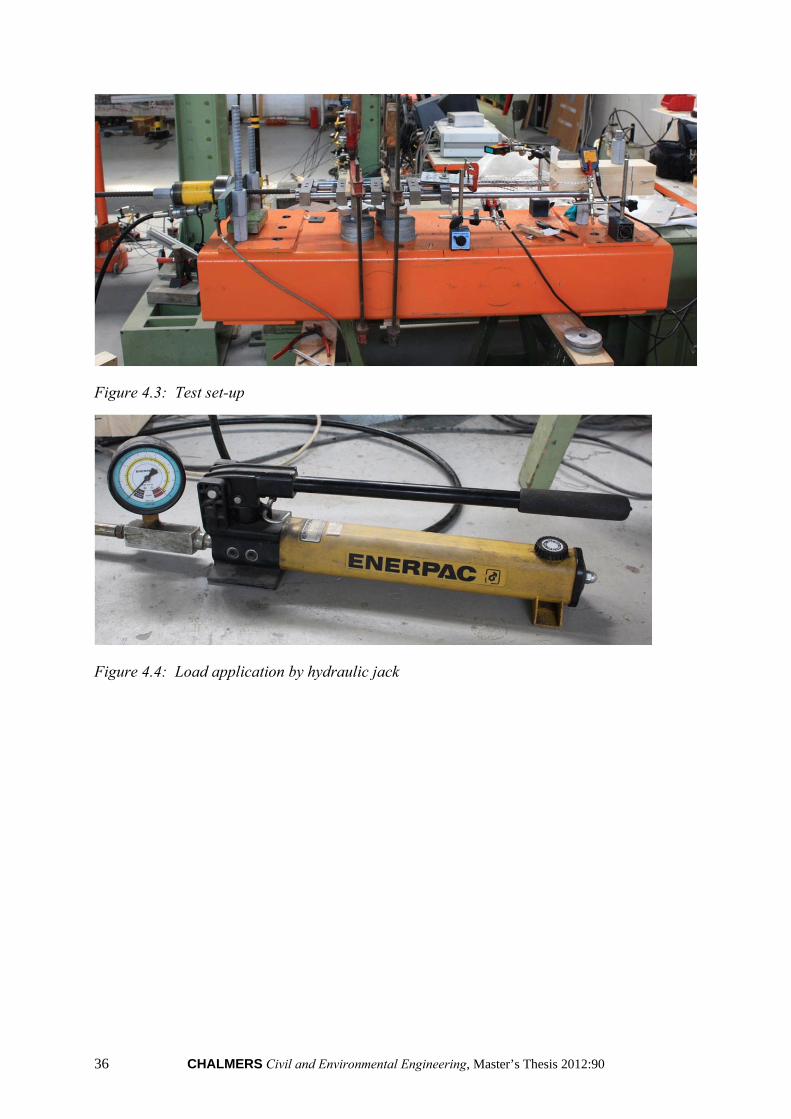
36 CHALMERS Civil and Environmental Engineering, Master’s Thesis 2012:90
Figure 4.3: Test set-up
Figure 4.4: Load application by hydraulic jack
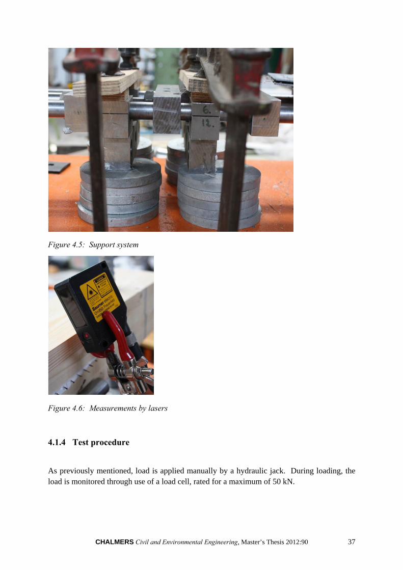
CHALMERS Civil and Environmental Engineering, Master’s Thesis 2012:90 37
Figure 4.5: Support system
Figure 4.6: Measurements by lasers
4.1.4 Test procedure
As previously mentioned, load is applied manually by a hydraulic jack. During loading, the load is monitored through use of a load cell, rated for a maximum of 50 kN.
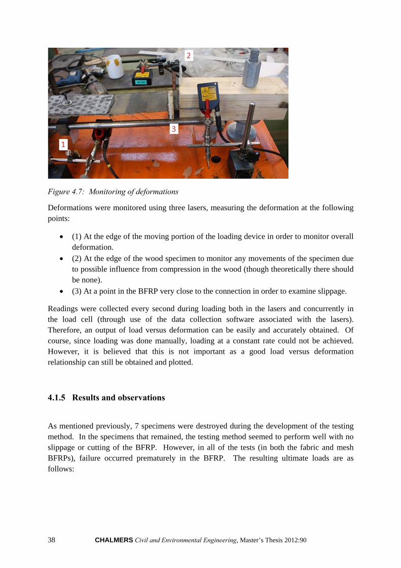
38 CHALMERS Civil and Environmental Engineering, Master’s Thesis 2012:90
Figure 4.7: Monitoring of deformations
Deformations were monitored using three lasers, measuring the deformation at the following points:
(1) At the edge of the moving portion of the loading device in order to monitor overall deformation.
(2) At the edge of the wood specimen to monitor any movements of the specimen due to possible influence from compression in the wood (though theoretically there should be none).
(3) At a point in the BFRP very close to the connection in order to examine slippage.
Readings were collected every second during loading both in the lasers and concurrently in the load cell (through use of the data collection software associated with the lasers). Therefore, an output of load versus deformation can be easily and accurately obtained. Of course, since loading was done manually, loading at a constant rate could not be achieved. However, it is believed that this is not important as a good load versus deformation relationship can still be obtained and plotted.
4.1.5 Results and observations
As mentioned previously, 7 specimens were destroyed during the development of the testing method. In the specimens that remained, the testing method seemed to perform well with no slippage or cutting of the BFRP. However, in all of the tests (in both the fabric and mesh BFRPs), failure occurred prematurely in the BFRP. The resulting ultimate loads are as follows:
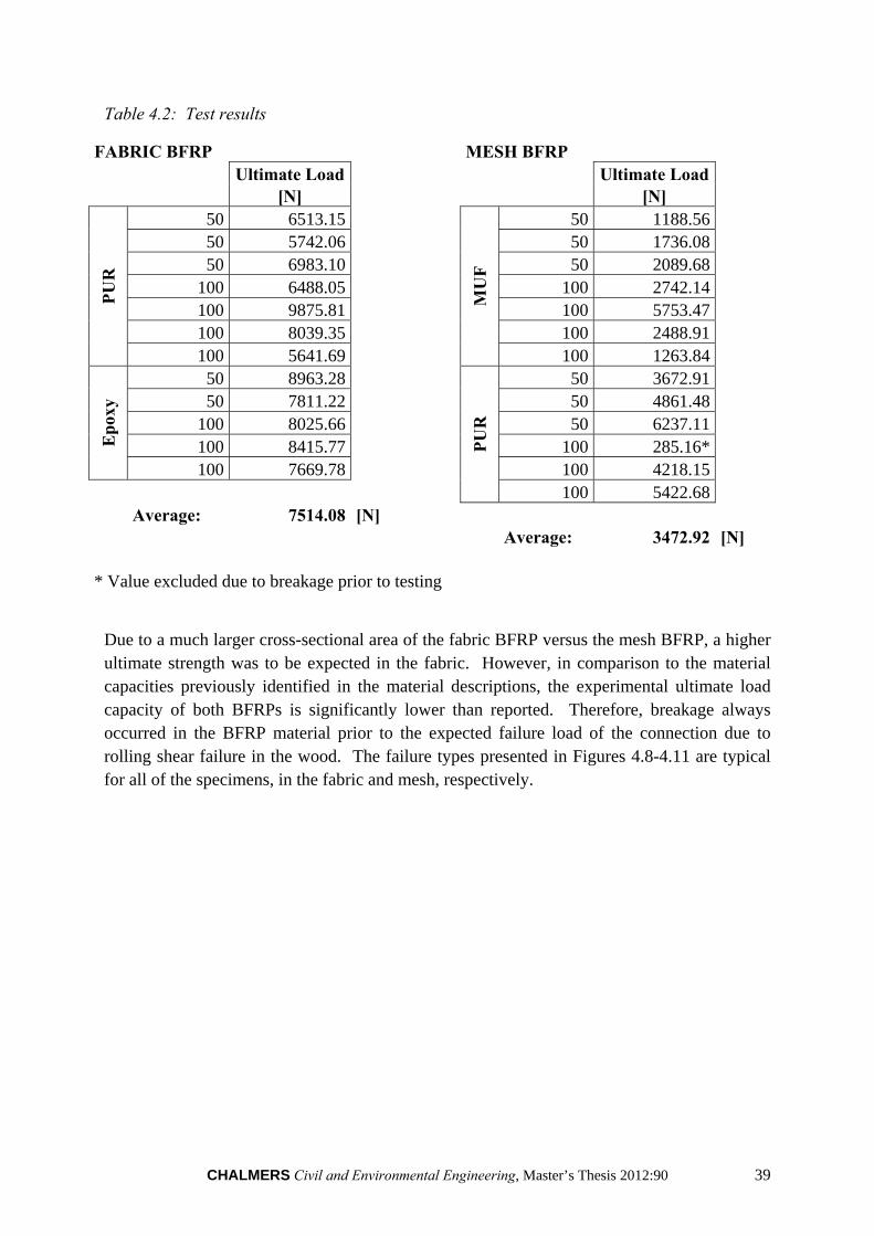
CHALMERS Civil and Environmental Engineering, Master’s Thesis 2012:90 39
Table 4.2: Test results
FABRIC BFRP MESH BFRP Ultimate Load Ultimate Load
[N] [N]
PU
R
50 6513.15
MU
F
50 1188.56 50 5742.06 50 1736.08 50 6983.10 50 2089.68
100 6488.05 100 2742.14 100 9875.81 100 5753.47 100 8039.35 100 2488.91 100 5641.69 100 1263.84
Ep
oxy
50 8963.28
PU
R
50 3672.91 50 7811.22 50 4861.48
100 8025.66 50 6237.11 100 8415.77 100 285.16* 100 7669.78 100 4218.15
100 5422.68 Average: 7514.08 [N]
Average: 3472.92 [N]
* Value excluded due to breakage prior to testing
Due to a much larger cross-sectional area of the fabric BFRP versus the mesh BFRP, a higher ultimate strength was to be expected in the fabric. However, in comparison to the material capacities previously identified in the material descriptions, the experimental ultimate load capacity of both BFRPs is significantly lower than reported. Therefore, breakage always occurred in the BFRP material prior to the expected failure load of the connection due to rolling shear failure in the wood. The failure types presented in Figures 4.8-4.11 are typical for all of the specimens, in the fabric and mesh, respectively.
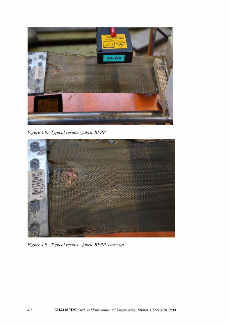
40 CHALMERS Civil and Environmental Engineering, Master’s Thesis 2012:90
Figure 4.8: Typical results - fabric BFRP
Figure 4.9: Typical results - fabric BFRP, close-up
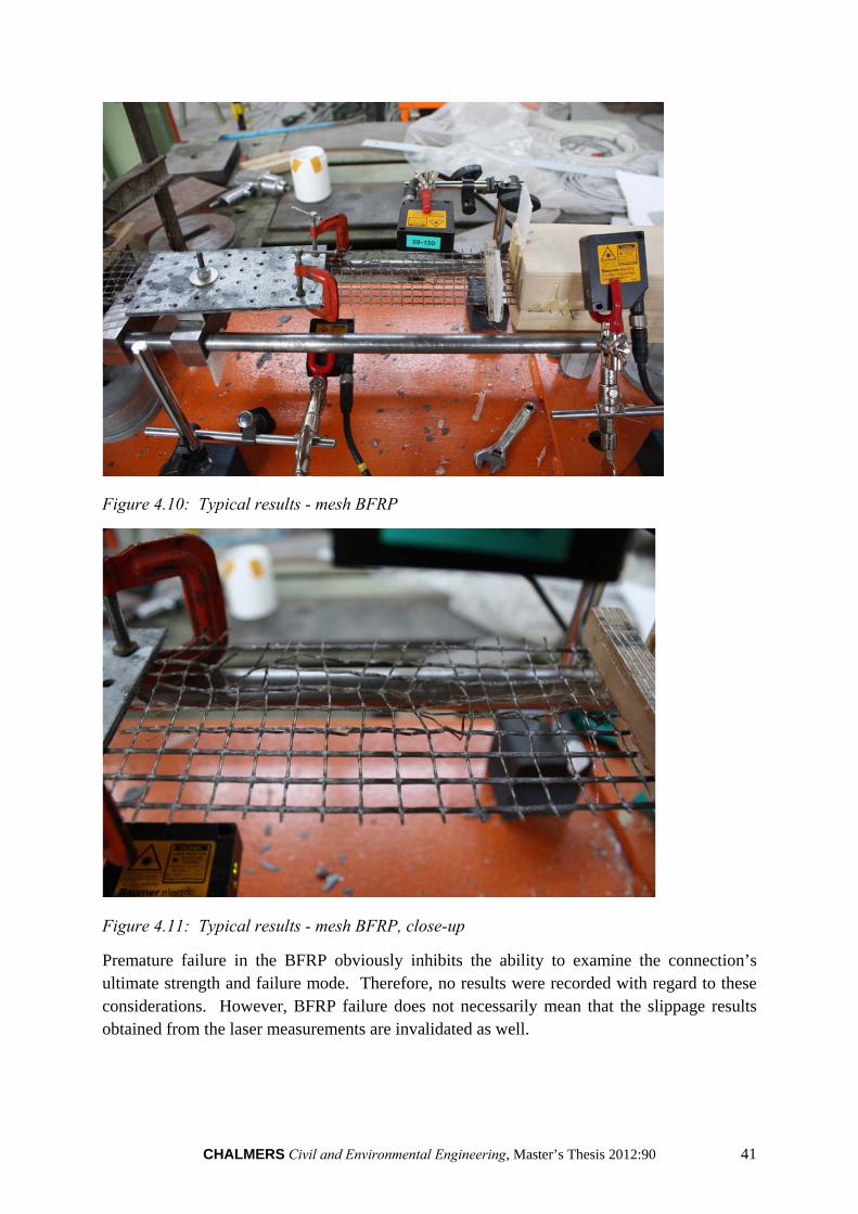
CHALMERS Civil and Environmental Engineering, Master’s Thesis 2012:90 41
Figure 4.10: Typical results - mesh BFRP
Figure 4.11: Typical results - mesh BFRP, close-up
Premature failure in the BFRP obviously inhibits the ability to examine the connection’s ultimate strength and failure mode. Therefore, no results were recorded with regard to these considerations. However, BFRP failure does not necessarily mean that the slippage results obtained from the laser measurements are invalidated as well.

42 CHALMERS Civil and Environmental Engineering, Master’s Thesis 2012:90
Accordingly, the elongation of the specimen as a whole shows good results, with a fairly linear load versus deformation relationship, with clearly defined points of interest such as beginning of breakage and full breakage in specimens which broke rapidly.
Figure 4.12: Typical elongation results
In Figure 4.12, the following characteristics can be noted:
An initial “tightening” of the fabric BFRP
Linear deformations
A slight indication where the load was briefly released at half-way
A sudden, brittle failure of the BFRP
Next, in attempting to isolate the slippage of the connection, the deformation measured by laser 2 and a percentage of the movement at laser 1 (to remove influence of elongation of the BFRP) are subtracted from the deformation measured by laser 3.
According to the results, a slippage of the connection of around 3mm before failure was recorded by the lasers. This could not be confirmed visually, as no movement could be seen either by visual inspection or by photographs.
0
1000
2000
3000
4000
5000
6000
7000
8000
0 2 4 6 8 10 12 14 16
Loa
d [
N]
Deformation [mm]
Elongation - Fabric, PUR, 50mm
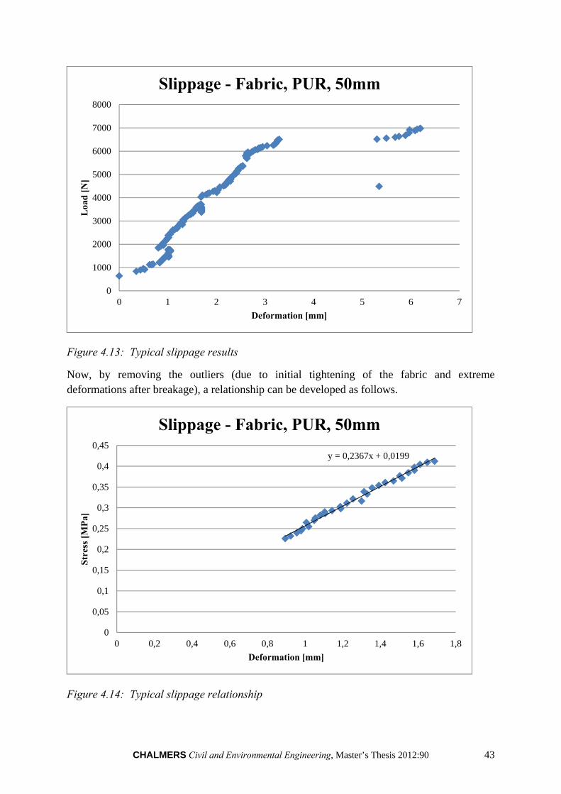
CHALMERS Civil and Environmental Engineering, Master’s Thesis 2012:90 43
Figure 4.13: Typical slippage results
Now, by removing the outliers (due to initial tightening of the fabric and extreme deformations after breakage), a relationship can be developed as follows.
Figure 4.14: Typical slippage relationship
0
1000
2000
3000
4000
5000
6000
7000
8000
0 1 2 3 4 5 6 7
Loa
d [
N]
Deformation [mm]
Slippage - Fabric, PUR, 50mm
y = 0,2367x + 0,0199
0
0,05
0,1
0,15
0,2
0,25
0,3
0,35
0,4
0,45
0 0,2 0,4 0,6 0,8 1 1,2 1,4 1,6 1,8
Str
ess
[MP
a]
Deformation [mm]
Slippage - Fabric, PUR, 50mm
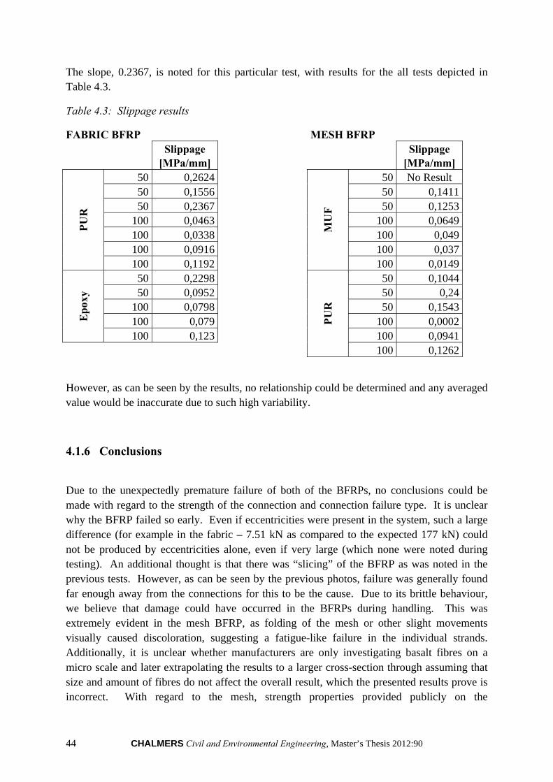
44 CHALMERS Civil and Environmental Engineering, Master’s Thesis 2012:90
The slope, 0.2367, is noted for this particular test, with results for the all tests depicted in Table 4.3.
Table 4.3: Slippage results
FABRIC BFRP MESH BFRP Slippage Slippage
[MPa/mm] [MPa/mm]
PU
R
50 0,2624
MU
F
50 No Result 50 0,1556 50 0,141150 0,2367 50 0,1253
100 0,0463 100 0,0649100 0,0338 100 0,049100 0,0916 100 0,037100 0,1192 100 0,0149
Ep
oxy
50 0,2298
PU
R
50 0,104450 0,0952 50 0,24
100 0,0798 50 0,1543100 0,079 100 0,0002100 0,123 100 0,0941
100 0,1262
However, as can be seen by the results, no relationship could be determined and any averaged value would be inaccurate due to such high variability.
4.1.6 Conclusions
Due to the unexpectedly premature failure of both of the BFRPs, no conclusions could be made with regard to the strength of the connection and connection failure type. It is unclear why the BFRP failed so early. Even if eccentricities were present in the system, such a large difference (for example in the fabric – 7.51 kN as compared to the expected 177 kN) could not be produced by eccentricities alone, even if very large (which none were noted during testing). An additional thought is that there was “slicing” of the BFRP as was noted in the previous tests. However, as can be seen by the previous photos, failure was generally found far enough away from the connections for this to be the cause. Due to its brittle behaviour, we believe that damage could have occurred in the BFRPs during handling. This was extremely evident in the mesh BFRP, as folding of the mesh or other slight movements visually caused discoloration, suggesting a fatigue-like failure in the individual strands. Additionally, it is unclear whether manufacturers are only investigating basalt fibres on a micro scale and later extrapolating the results to a larger cross-section through assuming that size and amount of fibres do not affect the overall result, which the presented results prove is incorrect. With regard to the mesh, strength properties provided publicly on the
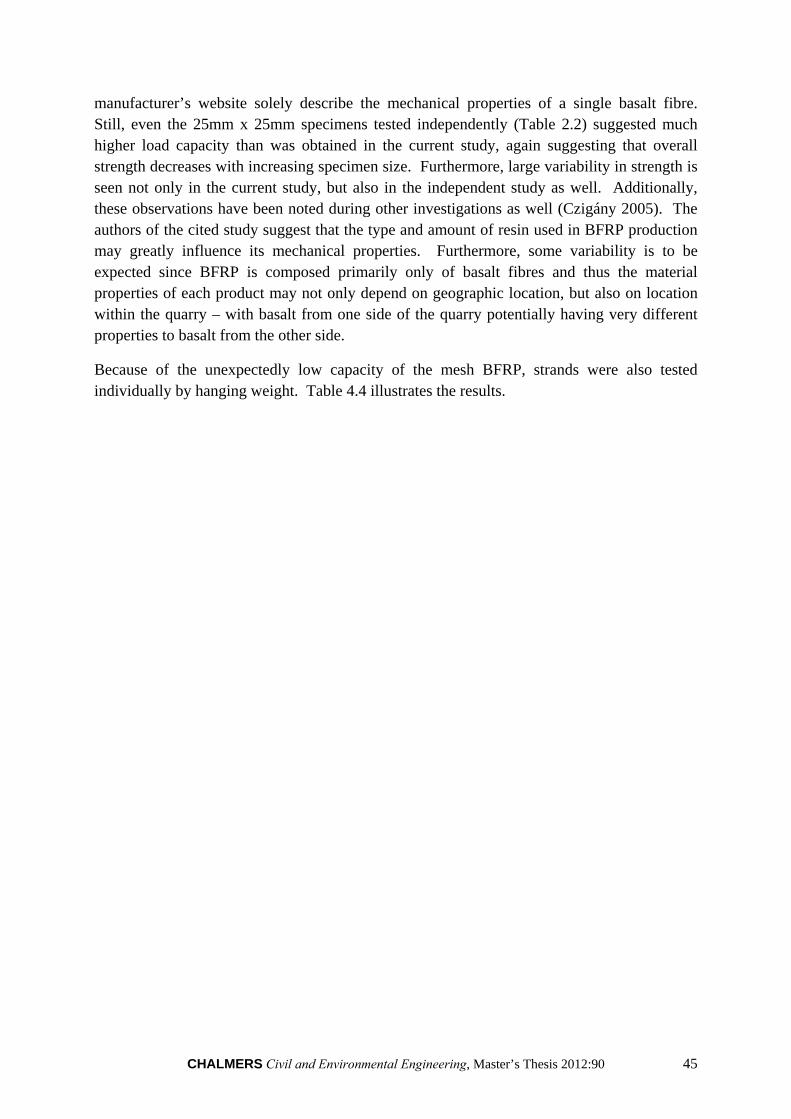
CHALMERS Civil and Environmental Engineering, Master’s Thesis 2012:90 45
manufacturer’s website solely describe the mechanical properties of a single basalt fibre. Still, even the 25mm x 25mm specimens tested independently (Table 2.2) suggested much higher load capacity than was obtained in the current study, again suggesting that overall strength decreases with increasing specimen size. Furthermore, large variability in strength is seen not only in the current study, but also in the independent study as well. Additionally, these observations have been noted during other investigations as well (Czigány 2005). The authors of the cited study suggest that the type and amount of resin used in BFRP production may greatly influence its mechanical properties. Furthermore, some variability is to be expected since BFRP is composed primarily only of basalt fibres and thus the material properties of each product may not only depend on geographic location, but also on location within the quarry – with basalt from one side of the quarry potentially having very different properties to basalt from the other side.
Because of the unexpectedly low capacity of the mesh BFRP, strands were also tested individually by hanging weight. Table 4.4 illustrates the results.
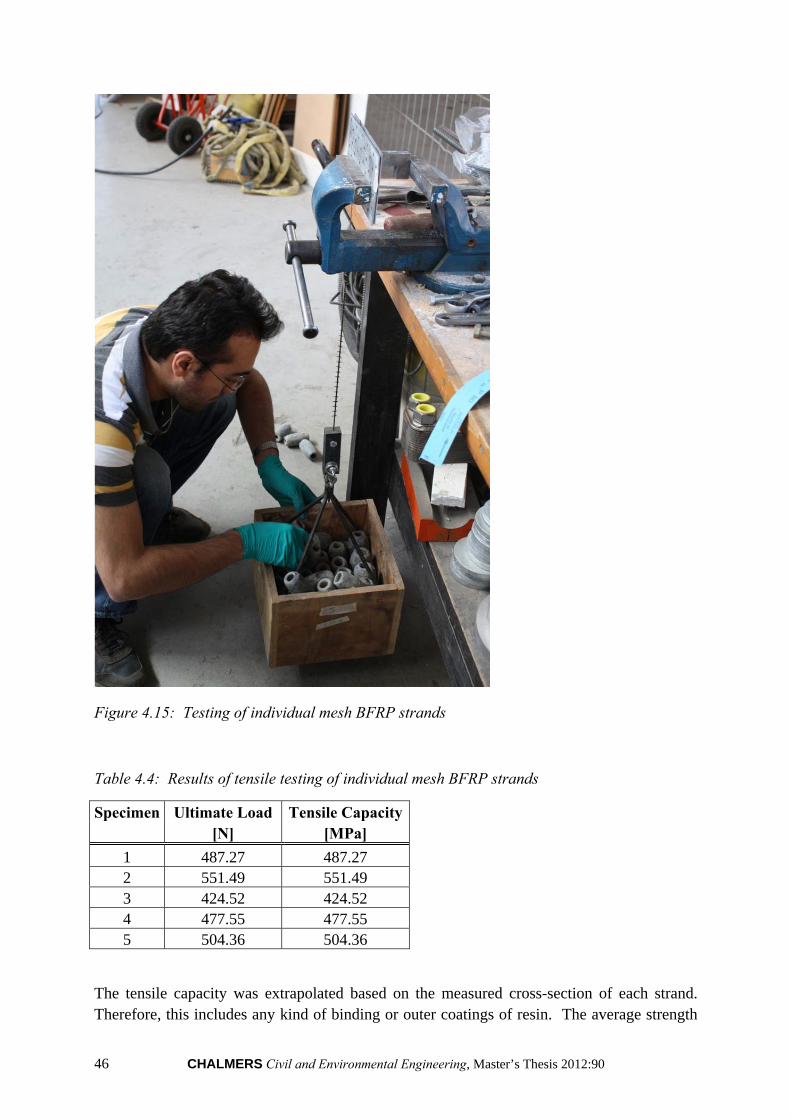
46 CHALMERS Civil and Environmental Engineering, Master’s Thesis 2012:90
Figure 4.15: Testing of individual mesh BFRP strands
Table 4.4: Results of tensile testing of individual mesh BFRP strands
Specimen Ultimate Load Tensile Capacity [N] [MPa]
1 487.27 487.27 2 551.49 551.49 3 424.52 424.52 4 477.55 477.55 5 504.36 504.36
The tensile capacity was extrapolated based on the measured cross-section of each strand. Therefore, this includes any kind of binding or outer coatings of resin. The average strength
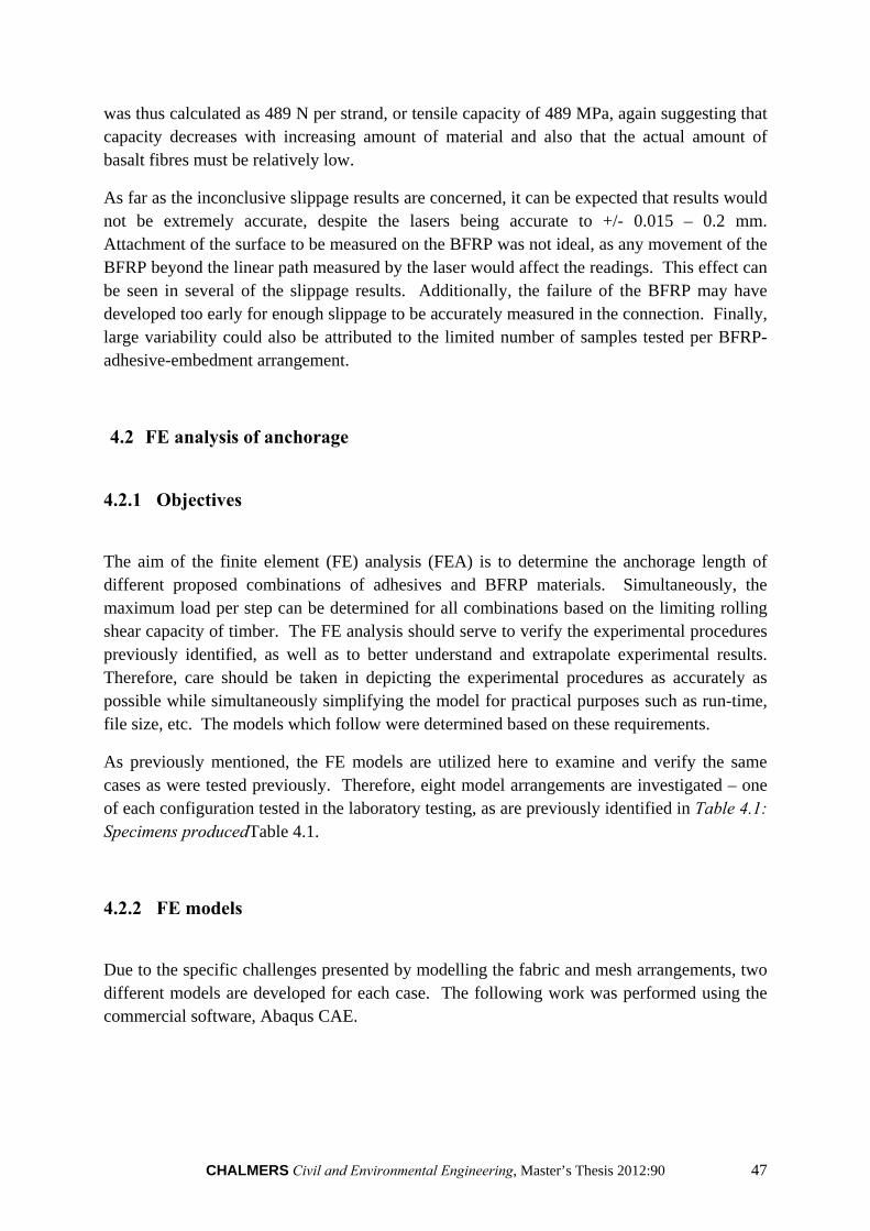
CHALMERS Civil and Environmental Engineering, Master’s Thesis 2012:90 47
was thus calculated as 489 N per strand, or tensile capacity of 489 MPa, again suggesting that capacity decreases with increasing amount of material and also that the actual amount of basalt fibres must be relatively low.
As far as the inconclusive slippage results are concerned, it can be expected that results would not be extremely accurate, despite the lasers being accurate to +/- 0.015 – 0.2 mm. Attachment of the surface to be measured on the BFRP was not ideal, as any movement of the BFRP beyond the linear path measured by the laser would affect the readings. This effect can be seen in several of the slippage results. Additionally, the failure of the BFRP may have developed too early for enough slippage to be accurately measured in the connection. Finally, large variability could also be attributed to the limited number of samples tested per BFRP-adhesive-embedment arrangement.
4.2 FE analysis of anchorage
4.2.1 Objectives
The aim of the finite element (FE) analysis (FEA) is to determine the anchorage length of different proposed combinations of adhesives and BFRP materials. Simultaneously, the maximum load per step can be determined for all combinations based on the limiting rolling shear capacity of timber. The FE analysis should serve to verify the experimental procedures previously identified, as well as to better understand and extrapolate experimental results. Therefore, care should be taken in depicting the experimental procedures as accurately as possible while simultaneously simplifying the model for practical purposes such as run-time, file size, etc. The models which follow were determined based on these requirements.
As previously mentioned, the FE models are utilized here to examine and verify the same cases as were tested previously. Therefore, eight model arrangements are investigated – one of each configuration tested in the laboratory testing, as are previously identified in Table 4.1: Specimens producedTable 4.1.
4.2.2 FE models
Due to the specific challenges presented by modelling the fabric and mesh arrangements, two different models are developed for each case. The following work was performed using the commercial software, Abaqus CAE.
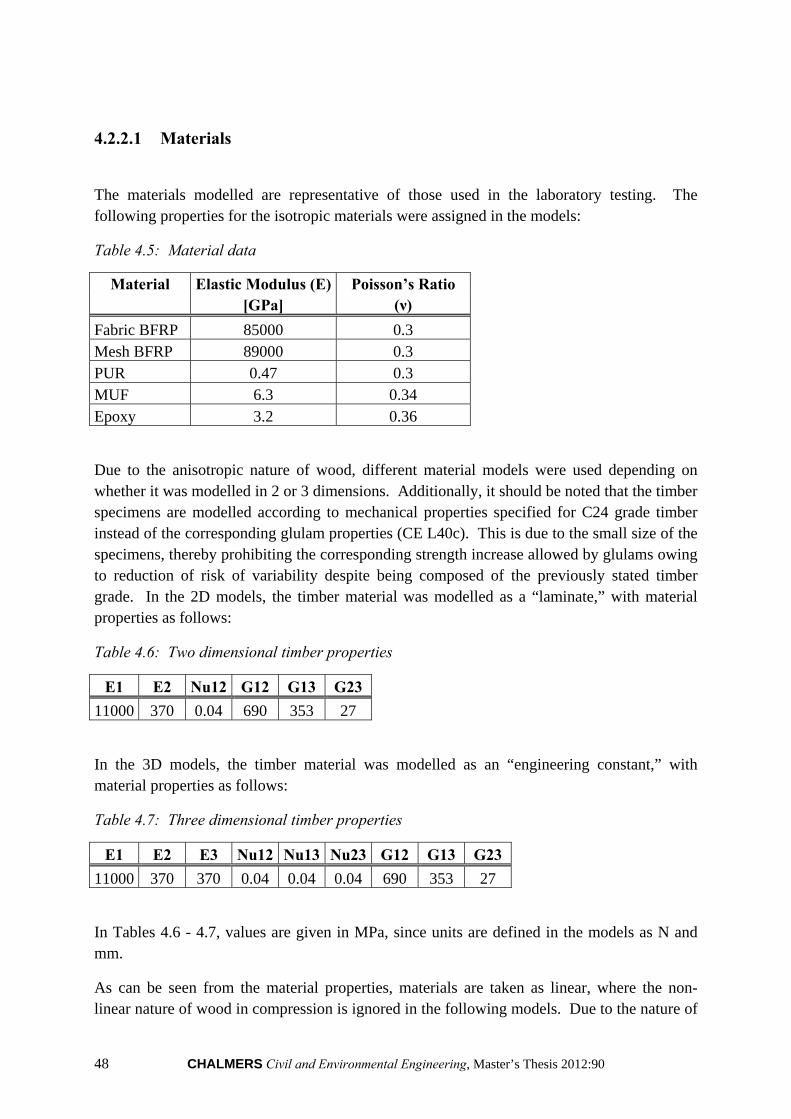
48 CHALMERS Civil and Environmental Engineering, Master’s Thesis 2012:90
4.2.2.1 Materials
The materials modelled are representative of those used in the laboratory testing. The following properties for the isotropic materials were assigned in the models:
Table 4.5: Material data
Material Elastic Modulus (E) Poisson’s Ratio [GPa] (ν)
Fabric BFRP 85000 0.3 Mesh BFRP 89000 0.3 PUR 0.47 0.3 MUF 6.3 0.34 Epoxy 3.2 0.36
Due to the anisotropic nature of wood, different material models were used depending on whether it was modelled in 2 or 3 dimensions. Additionally, it should be noted that the timber specimens are modelled according to mechanical properties specified for C24 grade timber instead of the corresponding glulam properties (CE L40c). This is due to the small size of the specimens, thereby prohibiting the corresponding strength increase allowed by glulams owing to reduction of risk of variability despite being composed of the previously stated timber grade. In the 2D models, the timber material was modelled as a “laminate,” with material properties as follows:
Table 4.6: Two dimensional timber properties
E1 E2 Nu12 G12 G13 G23
11000 370 0.04 690 353 27
In the 3D models, the timber material was modelled as an “engineering constant,” with material properties as follows:
Table 4.7: Three dimensional timber properties
E1 E2 E3 Nu12 Nu13 Nu23 G12 G13 G23
11000 370 370 0.04 0.04 0.04 690 353 27
In Tables 4.6 - 4.7, values are given in MPa, since units are defined in the models as N and mm.
As can be seen from the material properties, materials are taken as linear, where the non-linear nature of wood in compression is ignored in the following models. Due to the nature of
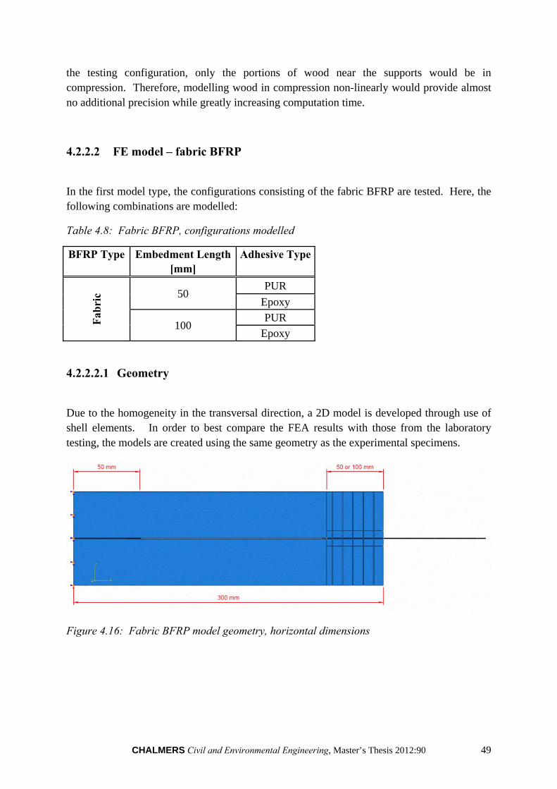
CHALMERS Civil and Environmental Engineering, Master’s Thesis 2012:90 49
the testing configuration, only the portions of wood near the supports would be in compression. Therefore, modelling wood in compression non-linearly would provide almost no additional precision while greatly increasing computation time.
4.2.2.2 FE model – fabric BFRP
In the first model type, the configurations consisting of the fabric BFRP are tested. Here, the following combinations are modelled:
Table 4.8: Fabric BFRP, configurations modelled
BFRP Type Embedment Length Adhesive Type [mm]
Fab
ric 50
PUR
Epoxy
100 PUR
Epoxy
4.2.2.2.1 Geometry
Due to the homogeneity in the transversal direction, a 2D model is developed through use of shell elements. In order to best compare the FEA results with those from the laboratory testing, the models are created using the same geometry as the experimental specimens.
Figure 4.16: Fabric BFRP model geometry, horizontal dimensions
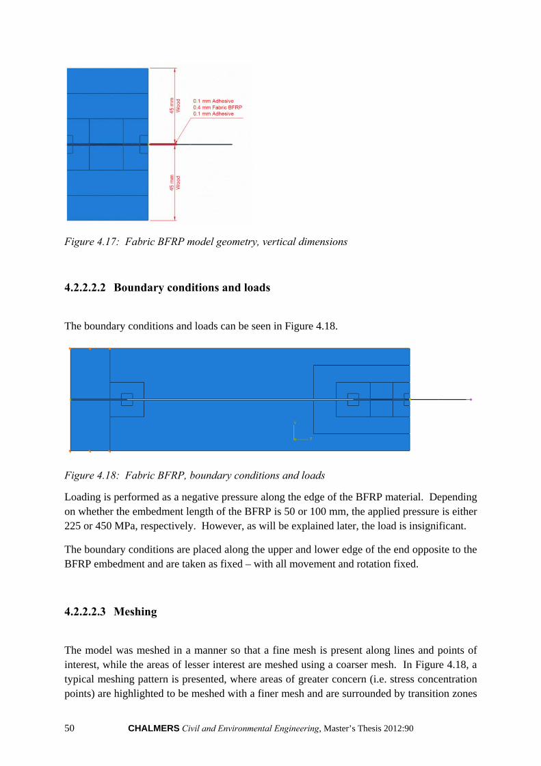
50 CHALMERS Civil and Environmental Engineering, Master’s Thesis 2012:90
Figure 4.17: Fabric BFRP model geometry, vertical dimensions
4.2.2.2.2 Boundary conditions and loads
The boundary conditions and loads can be seen in Figure 4.18.
Figure 4.18: Fabric BFRP, boundary conditions and loads
Loading is performed as a negative pressure along the edge of the BFRP material. Depending on whether the embedment length of the BFRP is 50 or 100 mm, the applied pressure is either 225 or 450 MPa, respectively. However, as will be explained later, the load is insignificant.
The boundary conditions are placed along the upper and lower edge of the end opposite to the BFRP embedment and are taken as fixed – with all movement and rotation fixed.
4.2.2.2.3 Meshing
The model was meshed in a manner so that a fine mesh is present along lines and points of interest, while the areas of lesser interest are meshed using a coarser mesh. In Figure 4.18, a typical meshing pattern is presented, where areas of greater concern (i.e. stress concentration points) are highlighted to be meshed with a finer mesh and are surrounded by transition zones
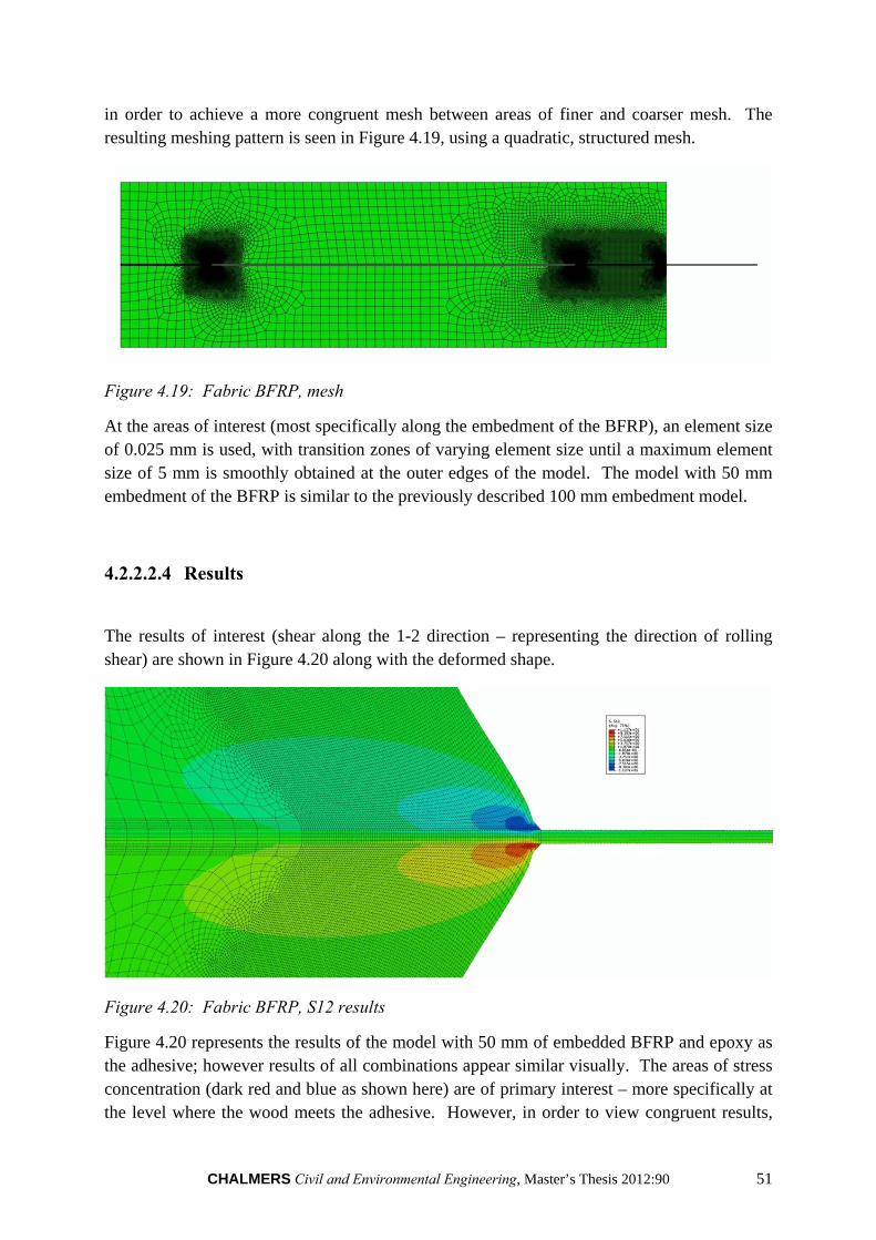
CHALMERS Civil and Environmental Engineering, Master’s Thesis 2012:90 51
in order to achieve a more congruent mesh between areas of finer and coarser mesh. The resulting meshing pattern is seen in Figure 4.19, using a quadratic, structured mesh.
Figure 4.19: Fabric BFRP, mesh
At the areas of interest (most specifically along the embedment of the BFRP), an element size of 0.025 mm is used, with transition zones of varying element size until a maximum element size of 5 mm is smoothly obtained at the outer edges of the model. The model with 50 mm embedment of the BFRP is similar to the previously described 100 mm embedment model.
4.2.2.2.4 Results
The results of interest (shear along the 1-2 direction – representing the direction of rolling shear) are shown in Figure 4.20 along with the deformed shape.
Figure 4.20: Fabric BFRP, S12 results
Figure 4.20 represents the results of the model with 50 mm of embedded BFRP and epoxy as the adhesive; however results of all combinations appear similar visually. The areas of stress concentration (dark red and blue as shown here) are of primary interest – more specifically at the level where the wood meets the adhesive. However, in order to view congruent results,
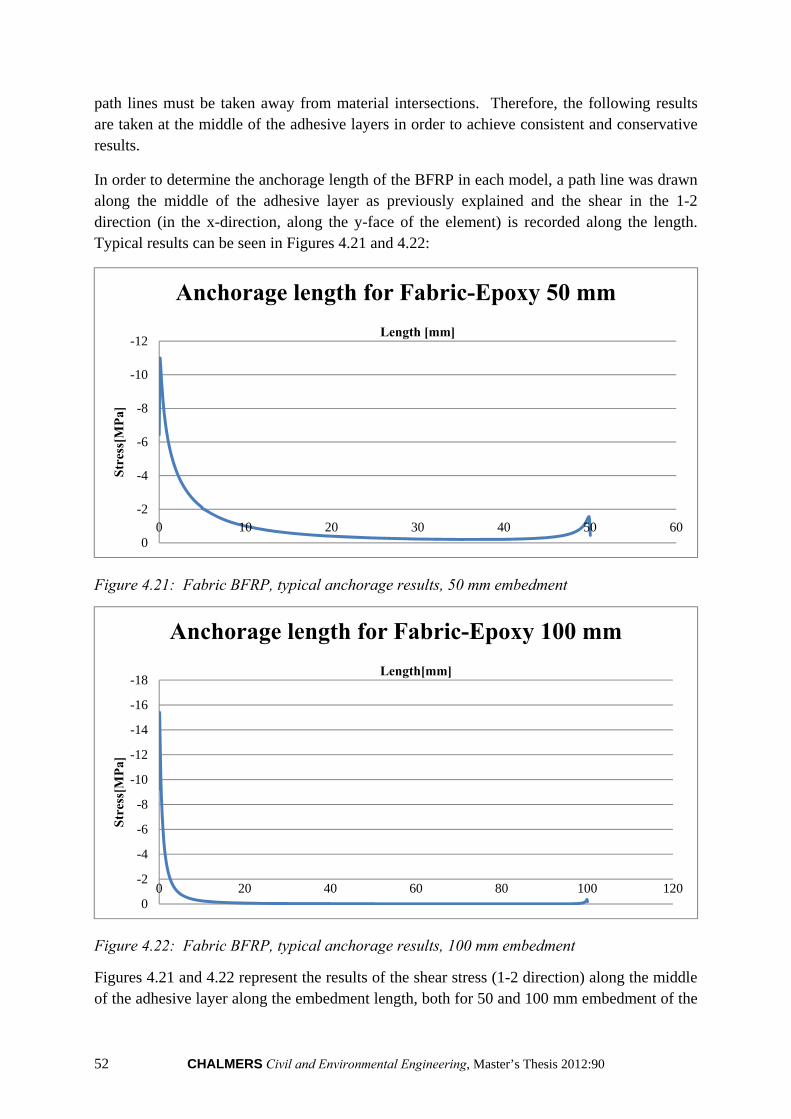
52 CHALMERS Civil and Environmental Engineering, Master’s Thesis 2012:90
path lines must be taken away from material intersections. Therefore, the following results are taken at the middle of the adhesive layers in order to achieve consistent and conservative results.
In order to determine the anchorage length of the BFRP in each model, a path line was drawn along the middle of the adhesive layer as previously explained and the shear in the 1-2 direction (in the x-direction, along the y-face of the element) is recorded along the length. Typical results can be seen in Figures 4.21 and 4.22:
Figure 4.21: Fabric BFRP, typical anchorage results, 50 mm embedment
Figure 4.22: Fabric BFRP, typical anchorage results, 100 mm embedment
Figures 4.21 and 4.22 represent the results of the shear stress (1-2 direction) along the middle of the adhesive layer along the embedment length, both for 50 and 100 mm embedment of the
-12
-10
-8
-6
-4
-2
00 10 20 30 40 50 60
Str
ess[
MP
a]
Length [mm]
Anchorage length for Fabric-Epoxy 50 mm
-18
-16
-14
-12
-10
-8
-6
-4
-2
00 20 40 60 80 100 120
Str
ess[
MP
a]
Length[mm]
Anchorage length for Fabric-Epoxy 100 mm

CHALMERS Civil and Environmental Engineering, Master’s Thesis 2012:90 53
BFRP. In the 50 mm embedment results, we can see a large influence from the stress concentration from the inner edge of the attachment of the BFRP. Due to the accumulative effect from the stress curve produced from this inner stress concentration, a value of 1% of the maximum stress is never reached along the curve – thus signifying that anchorage is not obtained. In the 100 mm embedment results, however, anchorage is reached at 13.6 mm – where 1% of the maximum stress is obtained (15.4 MPa maximum and therefore anchorage at 0.154 MPa). In addition to the anchorage results, an allowable ultimate load can be obtained by determining an appropriate reduction factor so that the maximum stress does not achieve the allowable load defined by the rolling shear capacity, ~1 MPa. Therefore, applying the coefficient, we achieve an allowable load for this example of:
115.4 ∙ 450 ∙ 36 1052
:
1
15.4
450
36
This same method is applied to all of the results for the fabric BFRP to obtain the following results as shown in Table 4.9:
Table 4.9: Fabric BFRP, summary of anchorage results
Allowable Load (N)
Anchorage Length (mm)
Fabric-Epoxy 50 mm 739 No Anchorage Length Fabric-Epoxy 100 mm 1052 13.6 Fabric-PUR 50 mm 1204 No Anchorage Length Fabric-PUR 100 mm 1898 18.2
As can be seen from Table 4.9, anchorage was not obtained in either of the 50 mm embedment tests. In examining the 100 mm embedment results, it can be seen that the epoxy achieves anchorage much sooner, but the PUR achieves a higher allowable load. Since both anchorage lengths are relatively small and any increase in allowable load is beneficial, it is assumed that based on these results, PUR would be the more appropriate adhesive for the fabric BFRP.
It should be noted that these results are determined based solely on E-modulus and Poisson’s ratio and assuming full interaction between materials. Obviously this would not be fully realistic as other concerns must also be investigated such as:
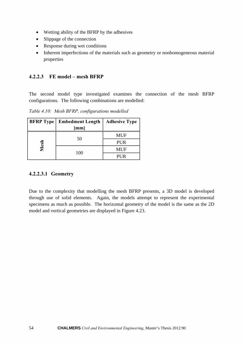
54 CHALMERS Civil and Environmental Engineering, Master’s Thesis 2012:90
Wetting ability of the BFRP by the adhesives
Slippage of the connection
Response during wet conditions
Inherent imperfections of the materials such as geometry or nonhomogeneous material properties
4.2.2.3 FE model – mesh BFRP
The second model type investigated examines the connection of the mesh BFRP configurations. The following combinations are modelled:
Table 4.10: Mesh BFRP, configurations modelled
BFRP Type Embedment Length Adhesive Type [mm]
Mes
h 50
MUF
PUR
100 MUF
PUR
4.2.2.3.1 Geometry
Due to the complexity that modelling the mesh BFRP presents, a 3D model is developed through use of solid elements. Again, the models attempt to represent the experimental specimens as much as possible. The horizontal geometry of the model is the same as the 2D model and vertical geometries are displayed in Figure 4.23.
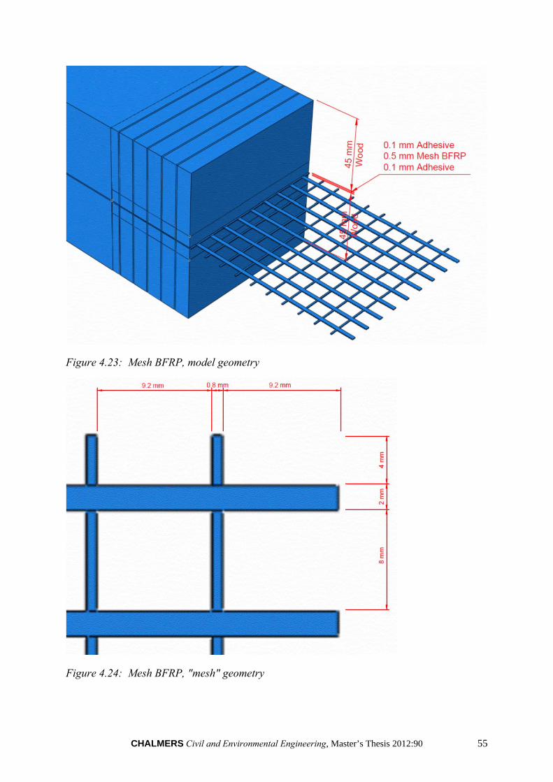
CHALMERS Civil and Environmental Engineering, Master’s Thesis 2012:90 55
Figure 4.23: Mesh BFRP, model geometry
Figure 4.24: Mesh BFRP, "mesh" geometry
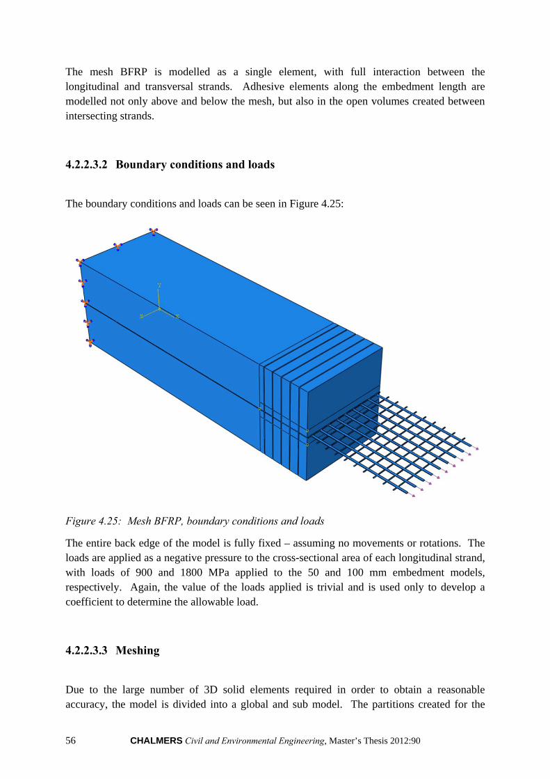
56 CHALMERS Civil and Environmental Engineering, Master’s Thesis 2012:90
The mesh BFRP is modelled as a single element, with full interaction between the longitudinal and transversal strands. Adhesive elements along the embedment length are modelled not only above and below the mesh, but also in the open volumes created between intersecting strands.
4.2.2.3.2 Boundary conditions and loads
The boundary conditions and loads can be seen in Figure 4.25:
Figure 4.25: Mesh BFRP, boundary conditions and loads
The entire back edge of the model is fully fixed – assuming no movements or rotations. The loads are applied as a negative pressure to the cross-sectional area of each longitudinal strand, with loads of 900 and 1800 MPa applied to the 50 and 100 mm embedment models, respectively. Again, the value of the loads applied is trivial and is used only to develop a coefficient to determine the allowable load.
4.2.2.3.3 Meshing
Due to the large number of 3D solid elements required in order to obtain a reasonable accuracy, the model is divided into a global and sub model. The partitions created for the

CHALMERS Civil and Environmental Engineering, Master’s Thesis 2012:90 57
global model can be seen in Figure 4.25, with the sub model being taken as the partitioned area closest to the connection. The sub model is taken as the length of the connection, by the width and by a total height of 14.7 mm. In Abaqus, first the global model is run and the result file can then be input when running the sub-model. Since boundaries are defined by the user to indicate the corresponding nodes in both the global and sub models, the results from the global model can successfully be used to run the sub model. Due to the size of both models (despite the division into global and sub models), it was necessary to run the models in a clustered computer setting (CLUSTER at Chalmers University of Technology).
In the global model, the minimum element size is 3 mm near the connection and increasing to 7 mm; meshed with a quadratic, structured mesh. In the sub model, the element size is 0.5 mm, with the adhesive layer being further subdivided into 2 elements along the height.
The current 50 mm embedment model is similar to that of the 100 mm embedment model.
Figure 4.26: Mesh BFRP, global model mesh
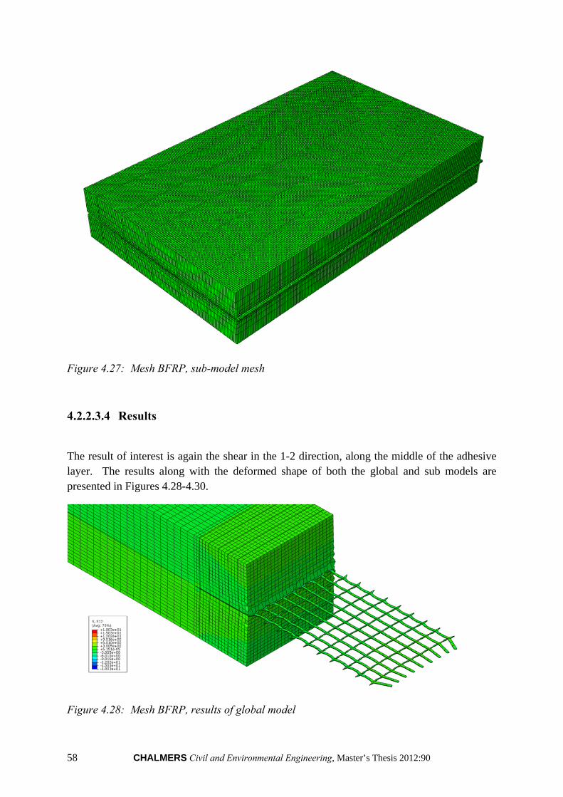
58 CHALMERS Civil and Environmental Engineering, Master’s Thesis 2012:90
Figure 4.27: Mesh BFRP, sub-model mesh
4.2.2.3.4 Results
The result of interest is again the shear in the 1-2 direction, along the middle of the adhesive layer. The results along with the deformed shape of both the global and sub models are presented in Figures 4.28-4.30.
Figure 4.28: Mesh BFRP, results of global model
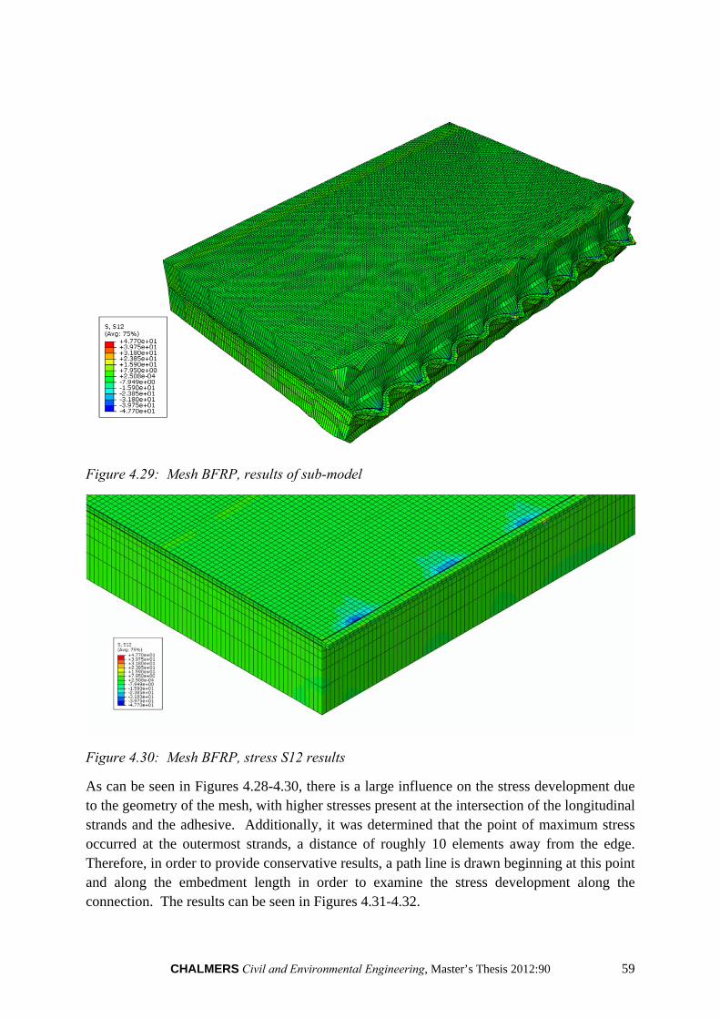
CHALMERS Civil and Environmental Engineering, Master’s Thesis 2012:90 59
Figure 4.29: Mesh BFRP, results of sub-model
Figure 4.30: Mesh BFRP, stress S12 results
As can be seen in Figures 4.28-4.30, there is a large influence on the stress development due to the geometry of the mesh, with higher stresses present at the intersection of the longitudinal strands and the adhesive. Additionally, it was determined that the point of maximum stress occurred at the outermost strands, a distance of roughly 10 elements away from the edge. Therefore, in order to provide conservative results, a path line is drawn beginning at this point and along the embedment length in order to examine the stress development along the connection. The results can be seen in Figures 4.31-4.32.
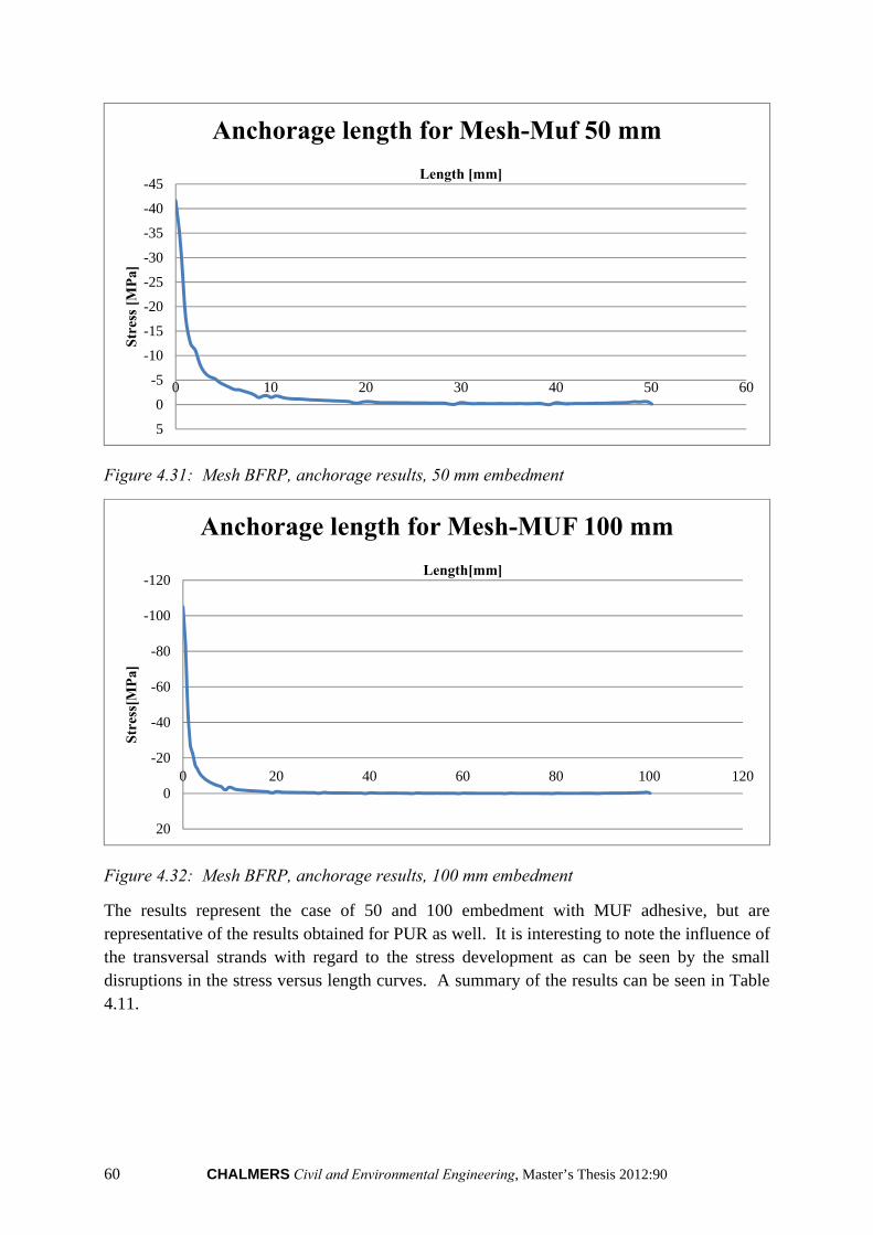
60 CHALMERS Civil and Environmental Engineering, Master’s Thesis 2012:90
Figure 4.31: Mesh BFRP, anchorage results, 50 mm embedment
Figure 4.32: Mesh BFRP, anchorage results, 100 mm embedment
The results represent the case of 50 and 100 embedment with MUF adhesive, but are representative of the results obtained for PUR as well. It is interesting to note the influence of the transversal strands with regard to the stress development as can be seen by the small disruptions in the stress versus length curves. A summary of the results can be seen in Table 4.11.
-45
-40
-35
-30
-25
-20
-15
-10
-5
0
5
0 10 20 30 40 50 60
Str
ess
[MP
a]
Length [mm]
Anchorage length for Mesh-Muf 50 mm
-120
-100
-80
-60
-40
-20
0
20
0 20 40 60 80 100 120
Str
ess[
MP
a]
Length[mm]
Anchorage length for Mesh-MUF 100 mm
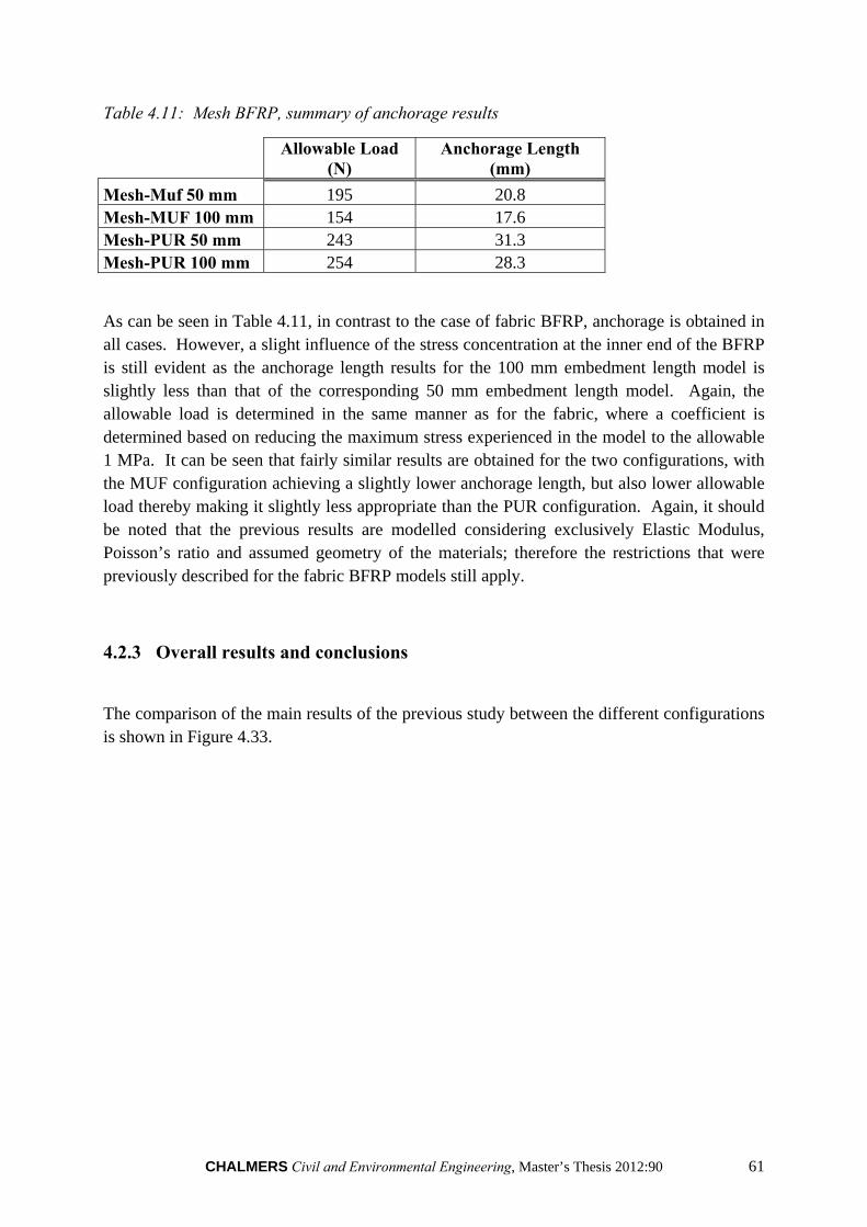
CHALMERS Civil and Environmental Engineering, Master’s Thesis 2012:90 61
Table 4.11: Mesh BFRP, summary of anchorage results
Allowable Load (N)
Anchorage Length (mm)
Mesh-Muf 50 mm 195 20.8 Mesh-MUF 100 mm 154 17.6 Mesh-PUR 50 mm 243 31.3 Mesh-PUR 100 mm 254 28.3
As can be seen in Table 4.11, in contrast to the case of fabric BFRP, anchorage is obtained in all cases. However, a slight influence of the stress concentration at the inner end of the BFRP is still evident as the anchorage length results for the 100 mm embedment length model is slightly less than that of the corresponding 50 mm embedment length model. Again, the allowable load is determined in the same manner as for the fabric, where a coefficient is determined based on reducing the maximum stress experienced in the model to the allowable 1 MPa. It can be seen that fairly similar results are obtained for the two configurations, with the MUF configuration achieving a slightly lower anchorage length, but also lower allowable load thereby making it slightly less appropriate than the PUR configuration. Again, it should be noted that the previous results are modelled considering exclusively Elastic Modulus, Poisson’s ratio and assumed geometry of the materials; therefore the restrictions that were previously described for the fabric BFRP models still apply.
4.2.3 Overall results and conclusions
The comparison of the main results of the previous study between the different configurations is shown in Figure 4.33.
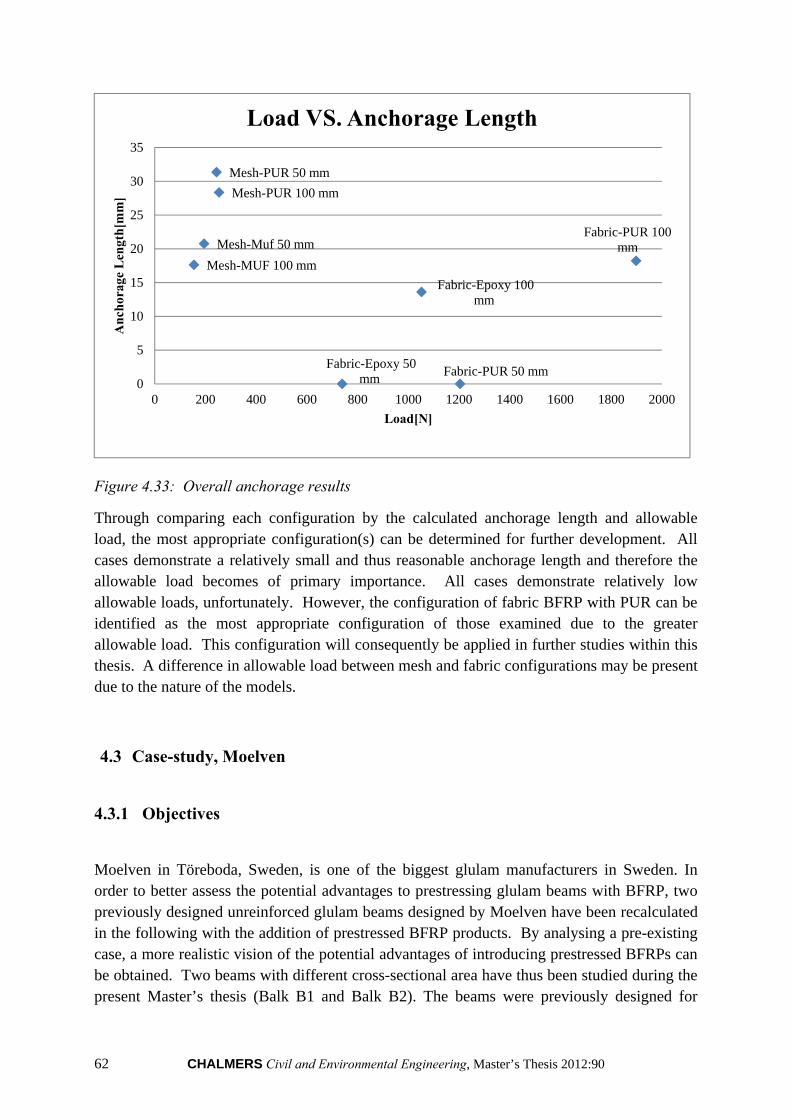
62 CHALMERS Civil and Environmental Engineering, Master’s Thesis 2012:90
Figure 4.33: Overall anchorage results
Through comparing each configuration by the calculated anchorage length and allowable load, the most appropriate configuration(s) can be determined for further development. All cases demonstrate a relatively small and thus reasonable anchorage length and therefore the allowable load becomes of primary importance. All cases demonstrate relatively low allowable loads, unfortunately. However, the configuration of fabric BFRP with PUR can be identified as the most appropriate configuration of those examined due to the greater allowable load. This configuration will consequently be applied in further studies within this thesis. A difference in allowable load between mesh and fabric configurations may be present due to the nature of the models.
4.3 Case-study, Moelven
4.3.1 Objectives
Moelven in Töreboda, Sweden, is one of the biggest glulam manufacturers in Sweden. In order to better assess the potential advantages to prestressing glulam beams with BFRP, two previously designed unreinforced glulam beams designed by Moelven have been recalculated in the following with the addition of prestressed BFRP products. By analysing a pre-existing case, a more realistic vision of the potential advantages of introducing prestressed BFRPs can be obtained. Two beams with different cross-sectional area have thus been studied during the present Master’s thesis (Balk B1 and Balk B2). The beams were previously designed for
Fabric-Epoxy 50 mm
Fabric-Epoxy 100 mm
Fabric-PUR 50 mm
Fabric-PUR 100 mmMesh-Muf 50 mm
Mesh-MUF 100 mm
Mesh-PUR 50 mm
Mesh-PUR 100 mm
0
5
10
15
20
25
30
35
0 200 400 600 800 1000 1200 1400 1600 1800 2000
An
chor
age
Len
gth
[mm
]
Load[N]
Load VS. Anchorage Length
CHALMERS Civil and Environmental Engineering, Master’s Thesis 2012:90 63
given load combinations and normal restrictions. The aim of our case-study was to assess any possible benefits from strengthening of these glulam beams by means of prestressed BFRPs, using the same load cases and restrictions as were previously considered.
4.3.2 Materials
4.3.2.1 Glulam
The beams were designed with glulam type CE L40c. The properties of this type of glulam are shown in Table 4.12 (All the values are in MPa):
Table 4.12: Glulam properties
Bending Capacity ,
Tensile Capacity , ,
Shear capacity ,
Elastic Modulus ,
Shear Modulus
30.8 25.4 2.7 13000 760
4.3.2.2 Beam Geometries
Table 4.13 shows the initial design of the height of the beams according to given load combinations and without any strengthening.
Table 4.13: Beam geometries
Beam type Height of beam [mm]
Width of beam [mm]
Number of lamellae
Balk B1 630 165 14 Balk B2 720 215 16
4.3.2.3 Prestressed BFRPs
The main principle which controls the design of the beam is the deflection in SLS and ULS, as is typically the case in glulam design. Therefore by prestressing the glulam, the deflection can be reduced and a smaller section could resist the same load combination. To achieve this, a numerical analysis was carried out with Matlab to find the maximum allowable prestressing force and determining the new cross-section size.
Two different types of BFRPs were considered for prestressing; fabric BFRP and a 10mm x 10mm mesh BFRP. The two types of BFRPs have the same size and properties as were used in the laboratory tests and FE-analyses.
64 CHALMERS Civil and Environmental Engineering, Master’s Thesis 2012:90
The properties of these two types are shown in Table 4.14:
Table 4.14: BFRP properties
BFRP Type
Tensile Capacity [MPa]
Elastic Modulus [MPa]
Section Height [mm]
Section Width [mm]
Fabric 4900 85000 0.4 Equal to width of beam
Mesh 2400 89000 0.5 Each strand is 2 mm wide. Number of strands depends on beam width.
4.3.3 Loads
The load combinations (SLS and ULS) including self-weight, permanent load and imposed load acting on each beam are shown in Tables 4.15 and 4.16.
Table 4.15: Loads considered, SLS
Beam type
Self-weight [kN/m]
Permanent Load [kN/m]
Imposed Load [kN/m]
Span Length [mm]
Balk B1 0.416 6.800 4.113 7800 Balk B2 0.619 13.600 6.613 7800
Table 4.16: Loads considered, ULS
Beam type
Self-weight [kN/m]
Permanent Load [kN/m]
Imposed Load [kN/m]
Span Length [mm]
Balk B1 0.499 8.160 12.339 7800 Balk B2 0.743 16.320 19.839 7800
4.3.4 Methodology
Step 1 (Input data)
In this step, the beam geometry, load combinations, designed cross section and other criteria were defined (span length, modification factor to determine the loads in ULS based on loads in SLS, deflection limits in both instantaneous and long-term).
Step 2 (Prestressing force)
In this step, the maximum prestressing force is calculated based on the capacity of the wood in both the tension and compression sides and also the maximum tensile capacity of BFRP. In the design of prestressing force, half of the tensile capacity of BFRP was considered due to possible imperfections.
CHALMERS Civil and Environmental Engineering, Master’s Thesis 2012:90 65
Step 3 (Function Opt-height)
To find the new height of the beam and number of lamellae with prestressed BFRP, a function was made which is called function “Opt-height.” This function checks the criteria for designing the beam and increases the initial height of the beam (h+h1) until it fulfils the demanded conditions of bending capacity, shear capacity, deflections and etc.
Step 3.1 (Checking the deflection)
This function first checks the deflections of the beams for both instantaneous and long-term limits and finds a new height of the beam which can resist the limits for the deflection. Here it should be noted that the program takes into account the creep effects recommended by Eurocode 5 (kdef), despite previous research suggesting that a decrease in long-term creep can be achieved by the introduction of a strengthening material (Hansson 2007). Thus, the results obtained are conservative. Additionally, the current program does not allow for initial precambering of the beam. However, the program could be easily adapted for this purpose.
Step 3.2 (Checking the Shear stress)
The second step in this function is checking the shear capacity of the beam and finding a new height which can resist the shear stress.
Step 3.3 (Checking the bending during prestressing)
The third step is checking the bending stress during prestressing; again for both tension and compression sides and the new height is found.
Step 3.4 (Checking the bending during loading)
The fourth step is checking the bending during the loading. First the tension side is checked and new height is found but for the compression side, a new function is made to check the plastic capacity of the beam.
Step 3.4.1 (Checking the compression side –Plastic function)
Since wood can plasticize in the compression side before the failure, a new function is made to check the plastic capacity of the wood. This function calculates the elastic/plastic strains and capacity and another Function “plast_x” determines the neutral axis in the plastic mode. Based on the result from these two functions, the Plastic moment capacity is calculated and in the next step the plastic moment is compared to the actual moment during loading and a new height is determined.
Step 3.5 (output)
When all the checks are carried out, the final optimized height of the beam is determined which can then be used to calculate the following:
All of the previously described procedures are summarized in the flowchart on the next page, and the actual code can be found in the Appendices:
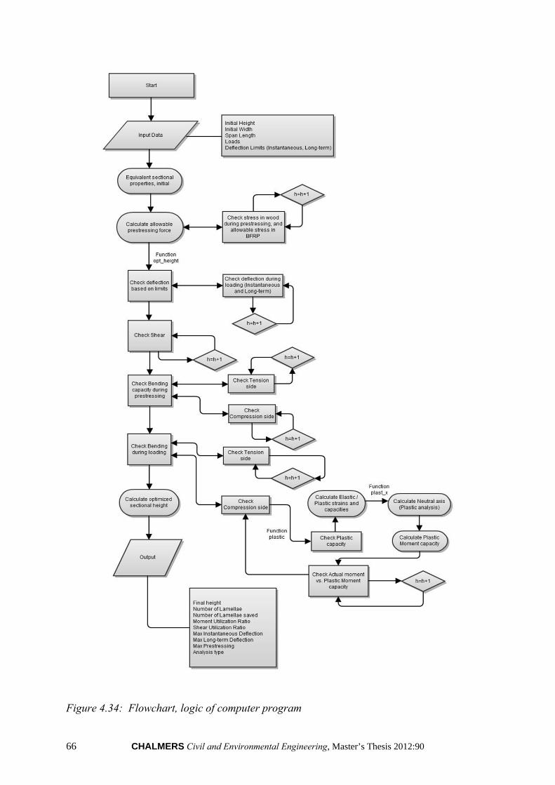
66 CHALMERS Civil and Environmental Engineering, Master’s Thesis 2012:90
Figure 4.34: Flowchart, logic of computer program

CHALMERS Civil and Environmental Engineering, Master’s Thesis 2012:90 67
4.3.5 Graphic user interface
To make a convenient way of working with this computational analysis, a graphic user interface is designed based on Matlab coding. It contains two parts: inputs and results. In the input fields all of the input data must be defined such as: initial geometry, loads in SLS, any additional desired load modification factor and finally the deflection limits. The results are determined based on the methods and code presented in the appendices and presented in the GUI are the following:
Final height
Number of lamellae
Number of lamellae saved
Moment utilization ratio
Shear utilization ratio
Maximum instantaneous deflection
Maximum Long-term deflection
Maximum applied prestressing
Analysis type
It must be noted that in the initial design of the glulam beams conducted by Moelven, all of the calculations were based on elastic analysis. During the numerical analysis however, we took advantage of the plastification limits of wood in compression side. This consideration is displayed under “Analysis Type,” where the type of case considered during design is shown (i.e. elastic or plastic). The final optimized glulam beam section with both configurations of prestressed BFRPs (i.e. fabric and mesh BFRP) according to the aforementioned geometry, material properties and loads, is demonstrated in Figures 4.35 and 4.36:

68 CHALMERS Civil and Environmental Engineering, Master’s Thesis 2012:90
Figure 4.35: Results of optimized glulam beam, Balk 1
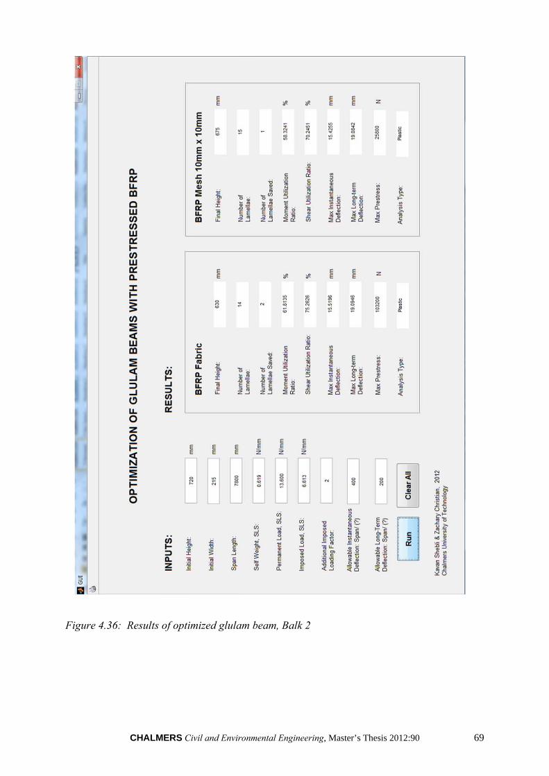
CHALMERS Civil and Environmental Engineering, Master’s Thesis 2012:90 69
Figure 4.36: Results of optimized glulam beam, Balk 2
70 CHALMERS Civil and Environmental Engineering, Master’s Thesis 2012:90
4.3.6 Results and conclusions
4.3.6.1 Prestressing force
The maximum allowable prestressing force depends primarily on the cross-section area of the BFRP product. Therefore, since the fabric BFRP has larger cross-sectional area, the allowable prestressing force is much higher than mesh BFRP.
Table 4.17: Maximum prestressing force [N]
Beam Type Fabric BFRP Mesh BFRP Balk B1 79200 19800 Balk B2 103200 25800
4.3.6.2 Performance
It can be concluded that the fabric BFRP provides better results when considering number of lamellae saved and reduction of the section height of the beam. This can be attributed directly to the higher allowable prestressing force since even during prestressing it was observed that in most cases the deflection limits controlled design.
Table 4.18: Summary of benefits from prestressed BFRP
Beam Type
Initial Height [mm]
Final Height, Prestressed
Fabric BFRP [mm]
Lamellae Saved, Prestressed
Fabric BFRP
Final Height, Prestressed Mesh BFRP
[mm]
Lamellae Saved, Prestressed Mesh BFRP
Balk B1 630 540 2 585 1 Balk B2 720 630 2 675 1
4.3.6.3 Further investigations
Additional analyses were carried out in order to attempt to determine the optimal BFRP geometries. The results show that increasing the cross-sectional area of BFRP results in higher prestressing force and consequently greater reduction of the beam height.
The example below demonstrates that if the cross-sectional area of the BFRPS increases four times the initial values, the height of the beam will dramatically decrease. The limiting factor to the increase in size of the BFRP cross-sectional area was found to be the curvature upwards during service loading.
Results of the additional analyses can be seen as follow in Tables 4.19-4.21:
CHALMERS Civil and Environmental Engineering, Master’s Thesis 2012:90 71
Table 4.19: Proposed new height of BFRP
BFRP Type Previous Section Height [mm]
Suggested Section Height [mm]
Fabric 0.4 1.0 Mesh 0.5 10
Table 4.20: New Maximum prestressing force [N]
Beam type
Previous PF, Fabric BFRP
New PF, Fabric BFRP
Previous PF, Mesh BFRP
New PF, Mesh BFRP
Balk B1 79200 198000 19800 198000 Balk B2 103200 258000 25800 258000
Table 4.21: Summary of benefits from new considered BFRP cross-sections
Beam Type
Initial Height [mm]
Final Height, Prestressed
Fabric BFRP [mm]
Lamellae Saved, Prestressed
Fabric BFRP
Final Height, Prestressed Mesh BFRP
[mm]
Lamellae Saved, Prestressed Mesh BFRP
Balk B1 630 450 4 450 4 Balk B2 720 540 4 540 4
For the beams in the previous case study, increasing the cross-section of the BFRPs more than four times the initial size of cross-section will no longer help in reducing the size of the beams, due to a large deflection upwards during the service state. It must be also noted that the prestressing force is further limited by tensile and compressive capacities of the glulam beam in bending due to prestressing, however the tensile strength of the BFRP generally controls if not the deflection upwards during the service state as previously described. During this further investigation, it was found that the limiting factor to the increased section height was negative curvature during service loading (considering only permanent loads). From this analysis, it was found that by increasing the BFRP cross-sections to the previously suggested sizes, the maximum number of lamellae saved in both cases was 4 – a 29 % height reduction in the beam “Balk B1.” When increasing the beam height such as in Balk B2, further increase of the BFRP cross-sectional is is allowable. Furthermore, it should be noted that during these cases, the maximum prestressing force was limited not by the cross-sectional area of the BFRP as was previously the case, but instead by the glulam strength characteristics.
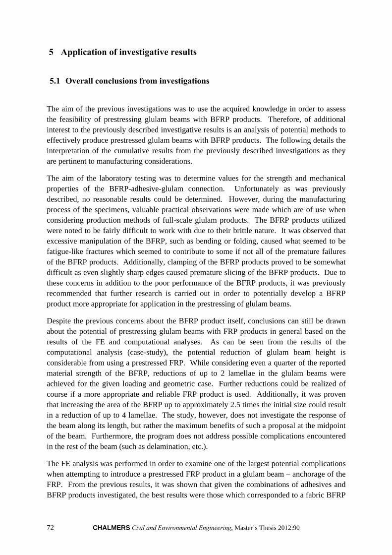
72 CHALMERS Civil and Environmental Engineering, Master’s Thesis 2012:90
5 Application of investigative results
5.1 Overall conclusions from investigations
The aim of the previous investigations was to use the acquired knowledge in order to assess the feasibility of prestressing glulam beams with BFRP products. Therefore, of additional interest to the previously described investigative results is an analysis of potential methods to effectively produce prestressed glulam beams with BFRP products. The following details the interpretation of the cumulative results from the previously described investigations as they are pertinent to manufacturing considerations.
The aim of the laboratory testing was to determine values for the strength and mechanical properties of the BFRP-adhesive-glulam connection. Unfortunately as was previously described, no reasonable results could be determined. However, during the manufacturing process of the specimens, valuable practical observations were made which are of use when considering production methods of full-scale glulam products. The BFRP products utilized were noted to be fairly difficult to work with due to their brittle nature. It was observed that excessive manipulation of the BFRP, such as bending or folding, caused what seemed to be fatigue-like fractures which seemed to contribute to some if not all of the premature failures of the BFRP products. Additionally, clamping of the BFRP products proved to be somewhat difficult as even slightly sharp edges caused premature slicing of the BFRP products. Due to these concerns in addition to the poor performance of the BFRP products, it was previously recommended that further research is carried out in order to potentially develop a BFRP product more appropriate for application in the prestressing of glulam beams.
Despite the previous concerns about the BFRP product itself, conclusions can still be drawn about the potential of prestressing glulam beams with FRP products in general based on the results of the FE and computational analyses. As can be seen from the results of the computational analysis (case-study), the potential reduction of glulam beam height is considerable from using a prestressed FRP. While considering even a quarter of the reported material strength of the BFRP, reductions of up to 2 lamellae in the glulam beams were achieved for the given loading and geometric case. Further reductions could be realized of course if a more appropriate and reliable FRP product is used. Additionally, it was proven that increasing the area of the BFRP up to approximately 2.5 times the initial size could result in a reduction of up to 4 lamellae. The study, however, does not investigate the response of the beam along its length, but rather the maximum benefits of such a proposal at the midpoint of the beam. Furthermore, the program does not address possible complications encountered in the rest of the beam (such as delamination, etc.).
The FE analysis was performed in order to examine one of the largest potential complications when attempting to introduce a prestressed FRP product in a glulam beam – anchorage of the FRP. From the previous results, it was shown that given the combinations of adhesives and BFRP products investigated, the best results were those which corresponded to a fabric BFRP
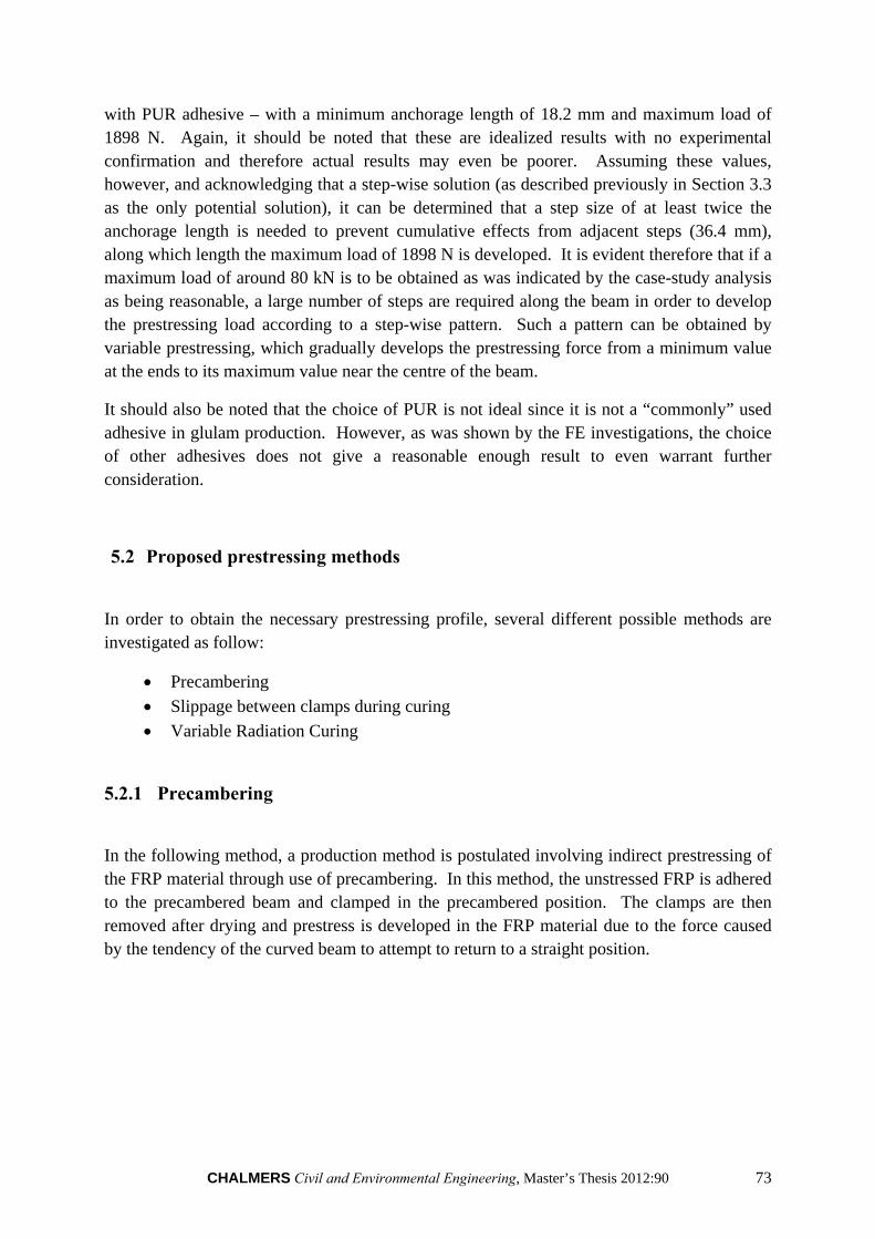
CHALMERS Civil and Environmental Engineering, Master’s Thesis 2012:90 73
with PUR adhesive – with a minimum anchorage length of 18.2 mm and maximum load of 1898 N. Again, it should be noted that these are idealized results with no experimental confirmation and therefore actual results may even be poorer. Assuming these values, however, and acknowledging that a step-wise solution (as described previously in Section 3.3 as the only potential solution), it can be determined that a step size of at least twice the anchorage length is needed to prevent cumulative effects from adjacent steps (36.4 mm), along which length the maximum load of 1898 N is developed. It is evident therefore that if a maximum load of around 80 kN is to be obtained as was indicated by the case-study analysis as being reasonable, a large number of steps are required along the beam in order to develop the prestressing load according to a step-wise pattern. Such a pattern can be obtained by variable prestressing, which gradually develops the prestressing force from a minimum value at the ends to its maximum value near the centre of the beam.
It should also be noted that the choice of PUR is not ideal since it is not a “commonly” used adhesive in glulam production. However, as was shown by the FE investigations, the choice of other adhesives does not give a reasonable enough result to even warrant further consideration.
5.2 Proposed prestressing methods
In order to obtain the necessary prestressing profile, several different possible methods are investigated as follow:
Precambering
Slippage between clamps during curing
Variable Radiation Curing
5.2.1 Precambering
In the following method, a production method is postulated involving indirect prestressing of the FRP material through use of precambering. In this method, the unstressed FRP is adhered to the precambered beam and clamped in the precambered position. The clamps are then removed after drying and prestress is developed in the FRP material due to the force caused by the tendency of the curved beam to attempt to return to a straight position.
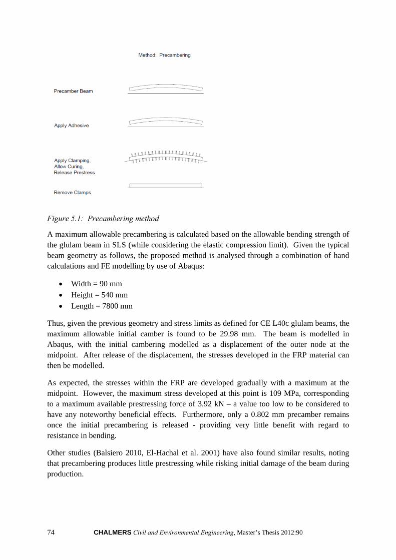
74 CHALMERS Civil and Environmental Engineering, Master’s Thesis 2012:90
Figure 5.1: Precambering method
A maximum allowable precambering is calculated based on the allowable bending strength of the glulam beam in SLS (while considering the elastic compression limit). Given the typical beam geometry as follows, the proposed method is analysed through a combination of hand calculations and FE modelling by use of Abaqus:
Width = 90 mm
Height = 540 mm
Length = 7800 mm
Thus, given the previous geometry and stress limits as defined for CE L40c glulam beams, the maximum allowable initial camber is found to be 29.98 mm. The beam is modelled in Abaqus, with the initial cambering modelled as a displacement of the outer node at the midpoint. After release of the displacement, the stresses developed in the FRP material can then be modelled.
As expected, the stresses within the FRP are developed gradually with a maximum at the midpoint. However, the maximum stress developed at this point is 109 MPa, corresponding to a maximum available prestressing force of 3.92 kN – a value too low to be considered to have any noteworthy beneficial effects. Furthermore, only a 0.802 mm precamber remains once the initial precambering is released - providing very little benefit with regard to resistance in bending.
Other studies (Balsiero 2010, El-Hachal et al. 2001) have also found similar results, noting that precambering produces little prestressing while risking initial damage of the beam during production.
CHALMERS Civil and Environmental Engineering, Master’s Thesis 2012:90 75
5.2.2 Slippage between clamps during curing
The current method attempts to utilize a novel variable prestressing technique investigated at the University of Maine (Davids et al. 2010). In this method, the prestressed FRP is introduced immediately after application of the adhesive. In the next step, the beam is clamped using a standard clamping force and distance as is the case for “special beams” currently produced in most glulam manufacturing facilities. Immediately after clamping, the prestressing is released and the prestress is allowed to be developed gradually along the length of the beam due to the partial restraint cause from the frictional forces under the clamps.
Figure 5.2: Slippage between clamps method
The previous investigation referenced was able to achieve good results at lower prestressing loads. However, from our own investigations into this method, modelling of this method in an appropriate way proved to be extremely difficult and therefore we are unsure how accurate the frictional losses (and therefore prestressing development) could be predicted prior to actual production. Furthermore, due to the previously detailed limitation presented by the allowable load and step size, an unreasonable amount of clamps would be required to properly insure anchorage of the FRP in the glulam beam.
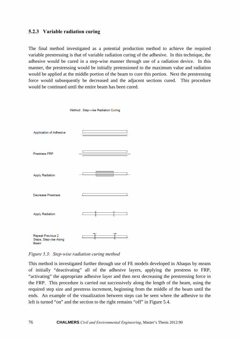
76 CHALMERS Civil and Environmental Engineering, Master’s Thesis 2012:90
5.2.3 Variable radiation curing
The final method investigated as a potential production method to achieve the required variable prestressing is that of variable radiation curing of the adhesive. In this technique, the adhesive would be cured in a step-wise manner through use of a radiation device. In this manner, the prestressing would be initially pretensioned to the maximum value and radiation would be applied at the middle portion of the beam to cure this portion. Next the prestressing force would subsequently be decreased and the adjacent sections cured. This procedure would be continued until the entire beam has been cured.
Figure 5.3: Step-wise radiation curing method
This method is investigated further through use of FE models developed in Abaqus by means of initially “deactivating” all of the adhesive layers, applying the prestress to FRP, “activating” the appropriate adhesive layer and then next decreasing the prestressing force in the FRP. This procedure is carried out successively along the length of the beam, using the required step size and prestress increment, beginning from the middle of the beam until the ends. An example of the visualization between steps can be seen where the adhesive to the left is turned “on” and the section to the right remains “off” in Figure 5.4.
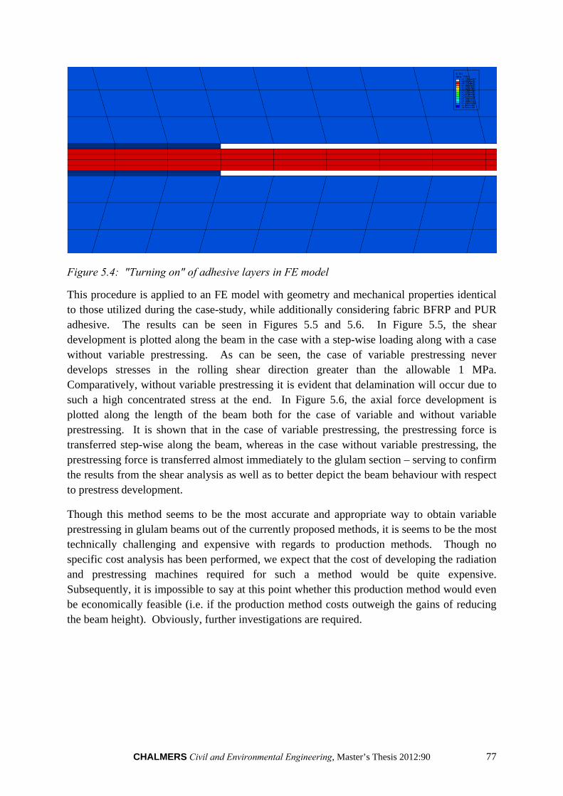
CHALMERS Civil and Environmental Engineering, Master’s Thesis 2012:90 77
Figure 5.4: "Turning on" of adhesive layers in FE model
This procedure is applied to an FE model with geometry and mechanical properties identical to those utilized during the case-study, while additionally considering fabric BFRP and PUR adhesive. The results can be seen in Figures 5.5 and 5.6. In Figure 5.5, the shear development is plotted along the beam in the case with a step-wise loading along with a case without variable prestressing. As can be seen, the case of variable prestressing never develops stresses in the rolling shear direction greater than the allowable 1 MPa. Comparatively, without variable prestressing it is evident that delamination will occur due to such a high concentrated stress at the end. In Figure 5.6, the axial force development is plotted along the length of the beam both for the case of variable and without variable prestressing. It is shown that in the case of variable prestressing, the prestressing force is transferred step-wise along the beam, whereas in the case without variable prestressing, the prestressing force is transferred almost immediately to the glulam section – serving to confirm the results from the shear analysis as well as to better depict the beam behaviour with respect to prestress development.
Though this method seems to be the most accurate and appropriate way to obtain variable prestressing in glulam beams out of the currently proposed methods, it is seems to be the most technically challenging and expensive with regards to production methods. Though no specific cost analysis has been performed, we expect that the cost of developing the radiation and prestressing machines required for such a method would be quite expensive. Subsequently, it is impossible to say at this point whether this production method would even be economically feasible (i.e. if the production method costs outweigh the gains of reducing the beam height). Obviously, further investigations are required.
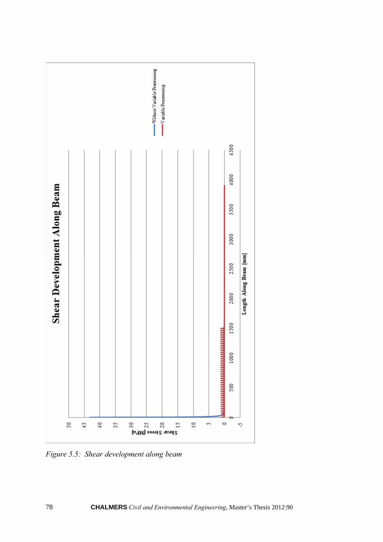
78 CHALMERS Civil and Environmental Engineering, Master’s Thesis 2012:90
Figure 5.5: Shear development along beam
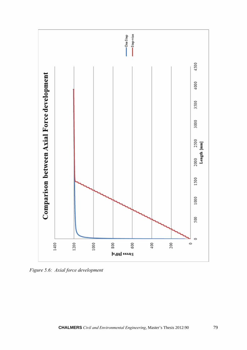
CHALMERS Civil and Environmental Engineering, Master’s Thesis 2012:90 79
Figure 5.6: Axial force development
80 CHALMERS Civil and Environmental Engineering, Master’s Thesis 2012:90
6 Conclusions
6.1 Concluding remarks
Prestressed Basalt Fibre Reinforced Polymer materials theoretically appear to be uniquely qualified for the application of prestressing glulam beams. However, during the previous investigations, it was seen that although BFRPs theoretically exhibit ideal characteristics for the prestressing of glulam beams, several difficulties were encountered that would suggest that significant additional research is needed prior to further consideration in such applications. Tests performed in this study showed that BFRPs are not only difficult to handle, but also do not exhibit such high strength in real applications as are advertised. Through an FE analysis of anchorage of FRP-glulam connections, it was also seen that due to the low rolling shear strength of timber, attachment of FRPs in glulams requires variable prestressing techniques with small step-sizes. These requirements were found to present significant complications during production as no “standard” production method was found to be suitable. All additional production methods were found to either be inadequate or complicated – with the proposed solution of variable radiation curing requiring potentially large investments and thereby raising the question of whether any gains achieved from prestressing glulam beams with BFRP would outweigh initial costs. Though theoretical calculations have shown that benefits could be significant as was demonstrated by the case-study, significant further investigation is needed into the previously presented complications before these benefits can be realized.
The following summarizes the main conclusions and observations that can be made from each of the previously presented investigations.
Laboratory testing:
BFRP failed at much lower loads than expected, before failure of the connection, and therefore no usable numerical results could be obtained.
BFRP material is extremely brittle, causing even slight manipulation of the BFRP product to produce fatigue-like damage.
Production of BFRP material more suited for these purposes should be developed before further consideration in strengthening of structural members.
Higher quality control of the BFRP products should be performed during manufacturing.
BFRP mesh is not straight – causing eccentricities during loading and difficulties during production of specimens.
FE analysis of anchorage:
Combination of fabric BFRP and PUR proved to be the most reasonable choice due to the highest allowable load and reasonable anchorage length. However, the allowable
CHALMERS Civil and Environmental Engineering, Master’s Thesis 2012:90 81
load per step is still relatively small, which requires a large number of steps (complicating manufacturing). It should be noted that changing the BFRP type or product could give very different results. Also, interaction between materials has been idealized and therefore realistic results could differ due to non-optimal adhesion.
The Mesh BFRP did achieve good anchorage as expected, however the allowable load per loading step is too small for practical purposes.
Case-study:
Theoretically, improvements are good – even when considering one quarter of the advertised strength of BFRP, the beam height can be reduced by 2 lamellae.
Beam reduction is limited by deflection criterion.
More FRP material could be added to achieve greater size reduction due to increasing allowable prestressing force; however, benefits are limited by negative curvature upwards in service state.
Application of investigative results:
No “easy” incorporation of FRP in glulam beam could be determined.
The most “plausible” production method, variable radiation curing, would require large investments – new machines, large production space and possibly long production times.
Not sure if gains from reducing beam height would outweigh costs.
82 CHALMERS Civil and Environmental Engineering, Master’s Thesis 2012:90
6.2 Recommendations for further research
Based on experience gained during the investigations, the following topics are identified as areas for further research to attempt to overcome the problems or difficulties of applying prestressed BFRP products to glulam beams and address concerns of feasibility:
BFRP products should be developed specifically for the application of prestressing glulam beams before further consideration of this topic. Despite the unexpectedly poor results of the BFRP products during laboratory testing, we believe that improvements could be made to the manufacturing process and content of the BFRP products so that it would be more suited for the investigated application. Additionally, recommendations as to proper handling techniques of the BFRP products should be given by the manufacturers.
Methods of producing BFRP with higher quality control.
Development of machines for radiation curing of glulam beams in the proposed manner.
The potential of using different amounts of hardener in adhesive along beam length to produce “step-wise” loading could be considered.
The potential of using rods or solid laminate of BFRP could be considered.
A cost analysis should be performed based on the results of the recommended further research in order to compare the benefits and costs prestressing glulam beams with BFRP products.
CHALMERS Civil and Environmental Engineering, Master’s Thesis 2012:90 83
7 References
Adhikari S. (2009): Mechanical Properties and Flexural Applications of Basalt Fibre Reinforced Polymer (BFRP) Bar. A Thesis Presented to The Graduate Faculty of The University of Akron.
Al-Emrani M., Haghani R., Kliger R. (2007): Control of interfacial stresses in beams
strengthened with prestressed CFRP laminates. Proceedings of the Asia-Pacific Conference on FRP in Structures (APFIS), 2007, Hong Kong, China: 1053-1060.
Balsiero A., Faria J., Negrão J. (2010): Prestressed Timber – Part 2: Tests on Structural
Beams. Barlow C.Y. , Woodhouse J. (1992): Micromechanics of permanent deformation in
softwood. University of Cambridge, Engineering department. Brady J.F., Harte A.M. (2008): Prestressed FRP Flexural Strengthening of Softwood Glue -
Laminated Timber Beams. Department of Civil Engineering, National University of Ireland, Galway (NUIG) Galway, Ireland.
Brunner M., and Schnueriger M.(2005): Timber Beams Strengthened by Attaching
Prestressed Carbon FRP Laminates with a Gradiented Anchoring Device. Proceedings of the International Symposium on Bond Behaviour of FRP in Structures (BBFS 2005).
Carolin A. (2003): Carbon fibre reinforced polymer for strengthening of Structural elements.
Department of Civil and Mining Engineering, Division of Structural Engineering, Luleå University of technology.
Chowdhury E. U., Green M. F., Bisby L.A., Bénichou N., Kodur V. K. R. (2007): Thermal
and Mechanical Characterization of Fibre Reinforced Polymers, Concrete, Steel, and Insulation Materials for use in Numerical Fire Endurance Modelling.
Collins M.P. , Mitchell D., (1991): Prestressed concrete structures. Prentice Hall, Englewood Cliffs, New Jersey 07632.
Czigány T.(2005): Basalt fiber reinforced hybrid polymer composites. Department of
Polymer Engineering, Budapest University of Technology and Economics. Dagher H.J., Davids W.G., Gray H., Nader J., Silva-Henriquez R. (2010): Strength
Performance of Prestressed Glass Fibre–Reinforced Polymer, Glued-Laminated Beams. Forrest Products Journal. Vol. 60, No.1.
Dagher H.J., Davids W.G., Gray H., Nader J., Silva-Henriquez R. (2010): Variable
Prestressing of FRP-Reinforced Glulam Beams: Methodology and Behavior. World Conference on Timber Engineering, 2010.
Dinges, T. (2009): The History of Prestressed Concrete: 188 to 1963. Department of
Architectural Engineering and Construction Science College of Engineering. Kansas State University.
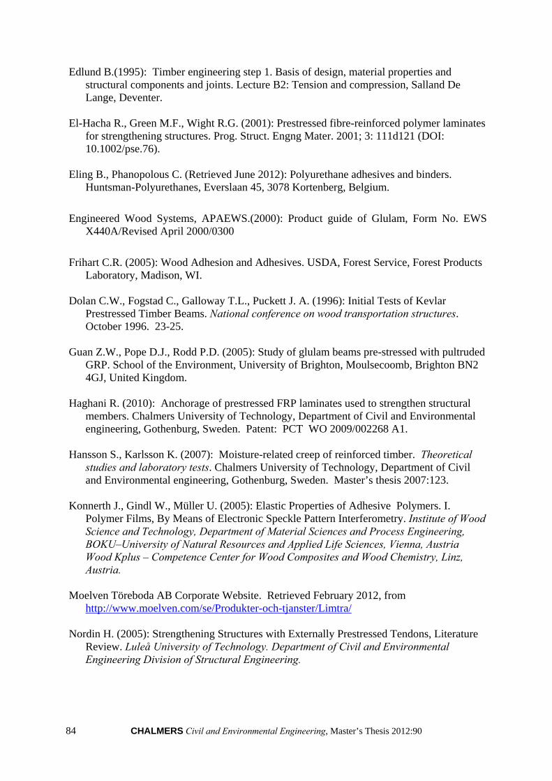
84 CHALMERS Civil and Environmental Engineering, Master’s Thesis 2012:90
Edlund B.(1995): Timber engineering step 1. Basis of design, material properties and structural components and joints. Lecture B2: Tension and compression, Salland De Lange, Deventer.
El-Hacha R., Green M.F., Wight R.G. (2001): Prestressed fibre-reinforced polymer laminates
for strengthening structures. Prog. Struct. Engng Mater. 2001; 3: 111d121 (DOI: 10.1002/pse.76).
Eling B., Phanopolous C. (Retrieved June 2012): Polyurethane adhesives and binders.
Huntsman-Polyurethanes, Everslaan 45, 3078 Kortenberg, Belgium.
Engineered Wood Systems, APAEWS.(2000): Product guide of Glulam, Form No. EWS X440A/Revised April 2000/0300
Frihart C.R. (2005): Wood Adhesion and Adhesives. USDA, Forest Service, Forest Products
Laboratory, Madison, WI. Dolan C.W., Fogstad C., Galloway T.L., Puckett J. A. (1996): Initial Tests of Kevlar
Prestressed Timber Beams. National conference on wood transportation structures. October 1996. 23-25.
Guan Z.W., Pope D.J., Rodd P.D. (2005): Study of glulam beams pre-stressed with pultruded
GRP. School of the Environment, University of Brighton, Moulsecoomb, Brighton BN2 4GJ, United Kingdom.
Haghani R. (2010): Anchorage of prestressed FRP laminates used to strengthen structural
members. Chalmers University of Technology, Department of Civil and Environmental engineering, Gothenburg, Sweden. Patent: PCT WO 2009/002268 A1.
Hansson S., Karlsson K. (2007): Moisture-related creep of reinforced timber. Theoretical
studies and laboratory tests. Chalmers University of Technology, Department of Civil and Environmental engineering, Gothenburg, Sweden. Master’s thesis 2007:123.
Konnerth J., Gindl W., Müller U. (2005): Elastic Properties of Adhesive Polymers. I. Polymer Films, By Means of Electronic Speckle Pattern Interferometry. Institute of Wood Science and Technology, Department of Material Sciences and Process Engineering, BOKU–University of Natural Resources and Applied Life Sciences, Vienna, Austria Wood Kplus – Competence Center for Wood Composites and Wood Chemistry, Linz, Austria.
Moelven Töreboda AB Corporate Website. Retrieved February 2012, from
http://www.moelven.com/se/Produkter-och-tjanster/Limtra/ Nordin H. (2005): Strengthening Structures with Externally Prestressed Tendons, Literature
Review. Luleå University of Technology. Department of Civil and Environmental Engineering Division of Structural Engineering.

CHALMERS Civil and Environmental Engineering, Master’s Thesis 2012:90 85
Patnaik A. (2009): Applications of Basalt Fibre Reinforced Polymer (BFRP) Reinforcement for Transportation Infrastructure. Department of Civil Engineering, The University of Akron , OH44325‐3905.
Parnas R., Shaw M., Liu Q. (2007): Basalt Fibre Reinforced Polymer Composites. Prepared
for the New England Transportation Consortium August, 2007 Project No. 03-7. Persson M., Wogelberg S. (2011): Analytical models of pre-stressed and reinforced glulam
beams – A competitive analysis of strengthened glulam beams. Chalmers University of Technology, Department of Civil and Environmental engineering, Gothenburg, Sweden.
Pizzi A. (2003): Melamine–Formaldehyde Adhesives. Ecole Nationale Supérieure des
Technologies et Industries du Bois, Universitéde Nancy 1, Epinal, France. Smarter Building Systems (2010): Comparative technical characteristics of filament made
from E-Glass, Basalt and Silica. Newport, Rhode Island USA. Svenskt Limträ AB. (2001): Limträ Pocket Guide (Guide to Glulam Beam in Swedish)
http://www.svensktlimtra.se/Upload/File/publikationer/pguide_2001.pdf.
Testa B.M. (Retrieved May 2012): ZAP. Engineered wood with Microwave and Radio Frequencies. http://www.apawood.org/EWTA/TechForum/ZAP.pdf.
TEXBAS TM Corporate Website. Retrieved May 2012, from www.texbas.eu.
Trada, Wood information (1992): Structural glued joints in timber. Timber Research and development association.
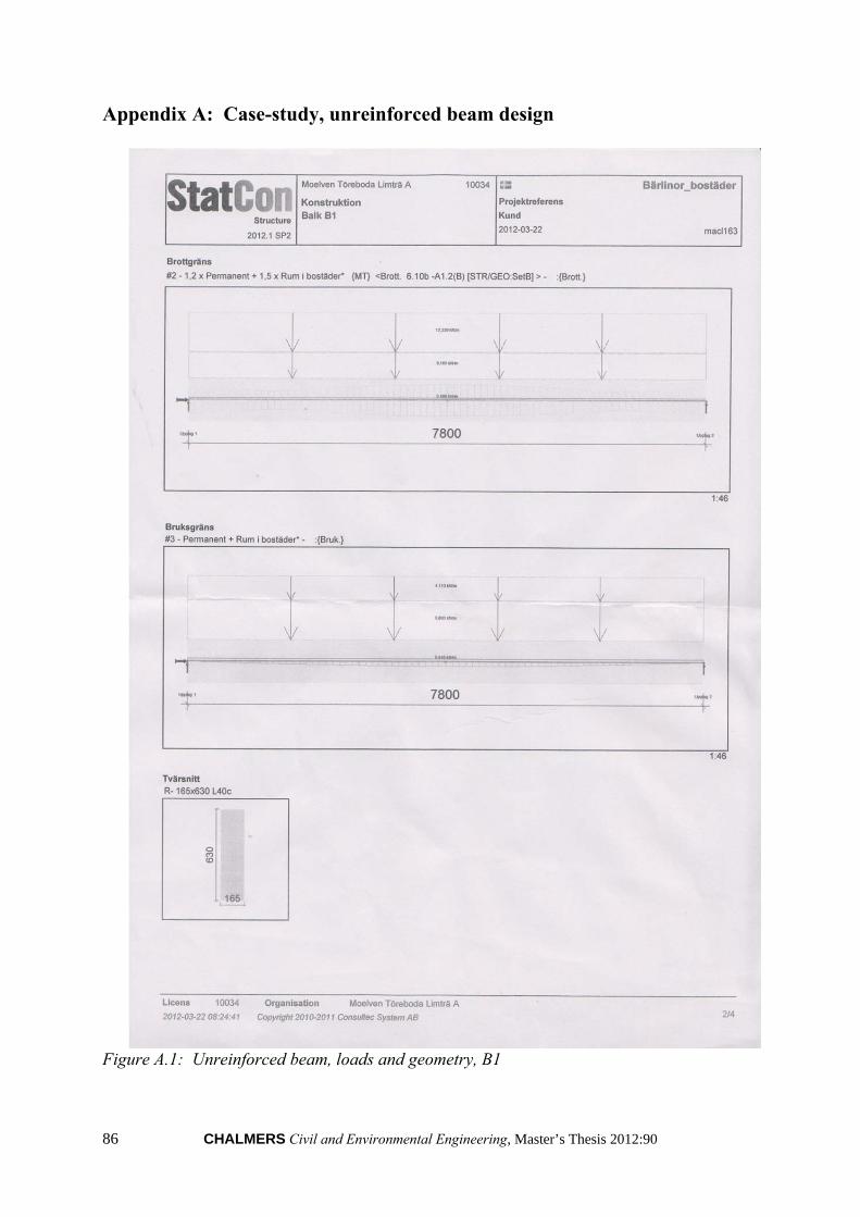
86 CHALMERS Civil and Environmental Engineering, Master’s Thesis 2012:90
Appendix A: Case-study, unreinforced beam design
Figure A.1: Unreinforced beam, loads and geometry, B1
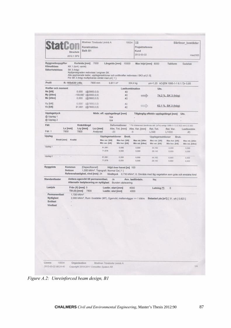
CHALMERS Civil and Environmental Engineering, Master’s Thesis 2012:90 87
Figure A.2: Unreinforced beam design, B1

88 CHALMERS Civil and Environmental Engineering, Master’s Thesis 2012:90
Figure A.3: Unreinforced beam, loads and geometry, B2
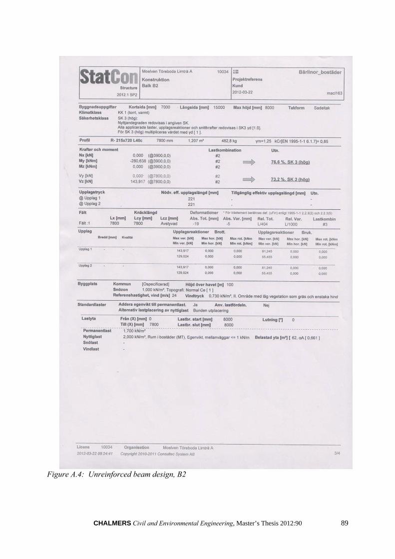
CHALMERS Civil and Environmental Engineering, Master’s Thesis 2012:90 89
Figure A.4: Unreinforced beam design, B2

90 CHALMERS Civil and Environmental Engineering, Master’s Thesis 2012:90
Appendix B: Matlab code for case-study
%%%%%%%%%%%%%%%%%%%%%%%%%%%%%%%%%%%%%%%%%%%%%%%%%%%%%%%%%%%%%%%%%%%%%%%%%%% % The main calculations file, % % for prestressed beams % % By: Kavan Shebli, Zachary Christian 2012 % % % %%%%%%%%%%%%%%%%%%%%%%%%%%%%%%%%%%%%%%%%%%%%%%%%%%%%%%%%%%%%%%%%%%%%%%%%%% function [output]=Function_section_opt(h,b,L,Pselfs,Ppers,Pimps,alfa_imp,Limit_inst,Limit_Long) %% The beams basic geometry % disp(sprintf('Inputs: \n')) % h=input('Please enter initial required beam height in mm: ');%[mm] Height % b=input('Please enter initial required beam width in mm: ');%[mm] Width % L=input('Please enter span length in mm: ');%[mm] Length, Simply Supported Ag=h*b; %[mm2] Area of Glulam Section %% Glulam CE L40c E=13000; %[MPa] youngs modulus G=720; %[MPa] Shear modulus fm=30.8; %[MPa] Bending strength ft=17.6; %[MPa] tensile strength fc=25.4; %[MPa] compressive strength fv=3.5; %[MPa] Shear strength dens=400; %[kg/m3] Density %% Loads % Loads in SLS qs=(Pselfs+Ppers+Pimps); %[N/mm] Total Distributed Load, SLS Vs=(qs)*L/2; %[N] Shear M_es=qs*L^2/8; % Loads in ULS % alfa_imp=input('Please enter additional imposed loading factor: '); gamma_perm=1.35; %Coefficient for Permanent Loads gamma_imp=1.5; %Coefficient for Imposed Loads Pselfu=Pselfs*gamma_perm; %[kN/m] Self weight Pperu=Ppers*gamma_perm; %[kN/m] Permanent Pimpu=Pimps*gamma_imp*alfa_imp; %[kN/m] Imposed Vu=(Pselfu+Pperu+Pimpu)*L/2; %[N] Shear qu=(Pselfu+Pperu+Pimpu); M_eu=qu*L^2/8; %% Reinforcement % tensile reinforcement - Basalt Fibre Fabric Ert(1)=85000; %[MPa] Youngs modulus bt(1)=b; %[mm] width of fabric
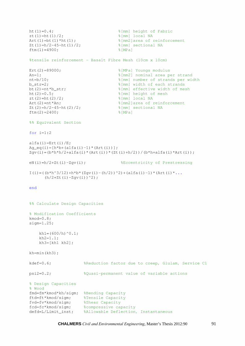
CHALMERS Civil and Environmental Engineering, Master’s Thesis 2012:90 91
ht(1)=0.4; %[mm] height of Fabric zt(1)=ht(1)/2; %[mm] local NA Art(1)=bt(1)*ht(1); %[mm2]area of reinforcement Zt(1)=h/2-45-ht(1)/2; %[mm] sectional NA ftm(1)=4900; %[MPa] %tensile reinforcement - Basalt Fibre Mesh (10cm x 10cm) Ert(2)=89000; %[MPa] Youngs modulus An=1; %[mm2] nominal area per strand nt=b/10; %[mm] number of strands per width b_str=2; %[mm] width of each strands bt(2)=nt*b_str; %[mm] effective width of mesh ht(2)=0.5; %[mm] height of mesh zt(2)=ht(2)/2; %[mm] local NA Art(2)=nt*An; %[mm2]area of reinforcement Zt(2)=h/2-45-ht(2)/2; %[mm] sectional NA ftm(2)=2400; %[MPa] %% Equivalent Section for i=1:2 alfa(i)=Ert(i)/E; Ag_eq(i)=[h*b+(alfa(i)-1)*(Art(i))]; Zgv(i)=(b*h*h/2+alfa(i)*(Art(i))*(Zt(i)+h/2))/(b*h+alfa(i)*Art(i)); eN(i)=h/2+Zt(i)-Zgv(i); %Eccentricity of Prestressing I(i)=((b*h^3/12)+h*b*(Zgv(i)-(h/2))^2)+(alfa(i)-1)*(Art(i)*... (h/2+Zt(i)-Zgv(i))^2); end %% Calculate Design Capacities % Modification Coefficients kmod=0.8; sigm=1.25; kh1=(600/h)^0.1; kh2=1.1; kh3=[kh1 kh2]; kh=min(kh3); kdef=0.6; %Reduction factor due to creep, Glulam, Service C1 psi2=0.2; %Quasi-permanent value of variable actions % Design Capacities % Wood fmd=fm*kmod*kh/sigm; %Bending Capacity ftd=ft*kmod/sigm; %Tensile Capacity fvd=fv*kmod/sigm; %Shear Capacity fcd=fc*kmod/sigm; %compressive capacity defd=L/Limit_inst; %Allowable Deflection, Instantaneous
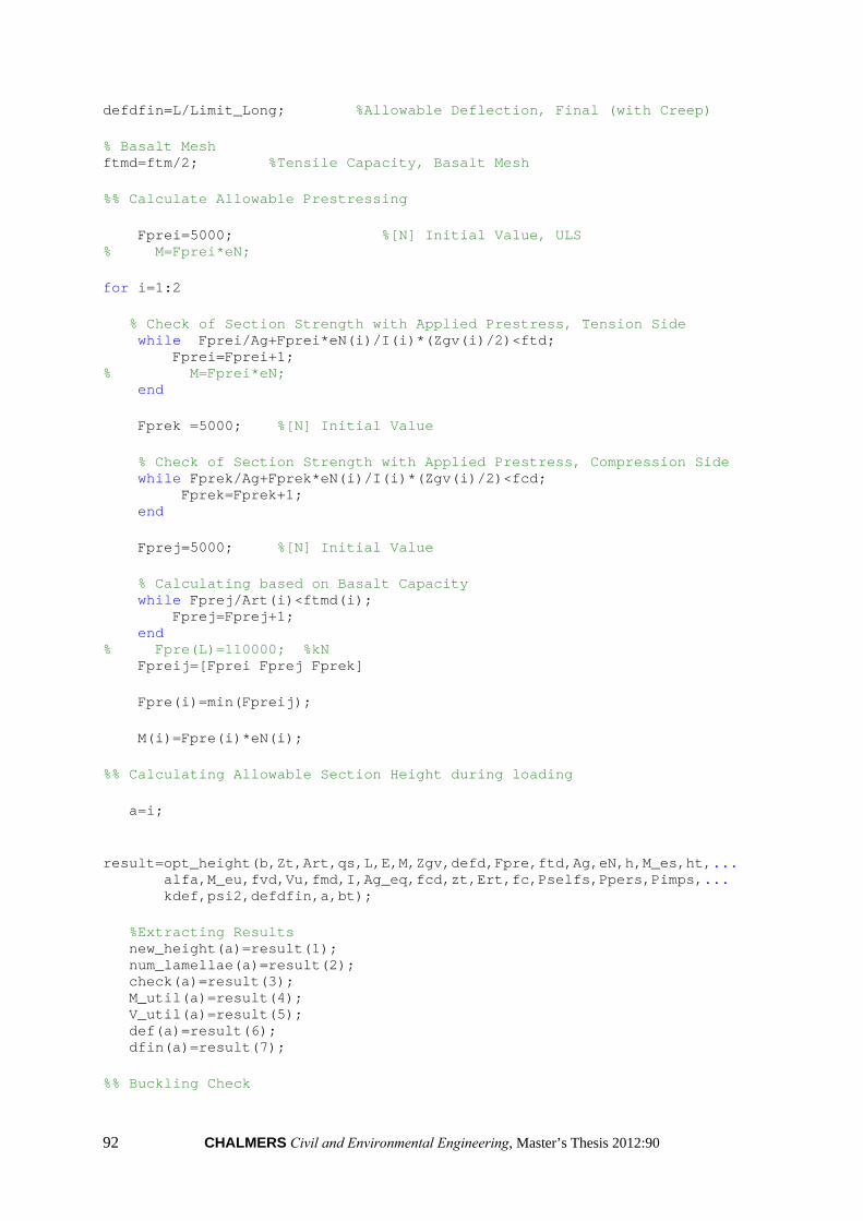
92 CHALMERS Civil and Environmental Engineering, Master’s Thesis 2012:90
defdfin=L/Limit_Long; %Allowable Deflection, Final (with Creep) % Basalt Mesh ftmd=ftm/2; %Tensile Capacity, Basalt Mesh %% Calculate Allowable Prestressing Fprei=5000; %[N] Initial Value, ULS % M=Fprei*eN; for i=1:2 % Check of Section Strength with Applied Prestress, Tension Side while Fprei/Ag+Fprei*eN(i)/I(i)*(Zgv(i)/2)<ftd; Fprei=Fprei+1; % M=Fprei*eN; end Fprek =5000; %[N] Initial Value % Check of Section Strength with Applied Prestress, Compression Side while Fprek/Ag+Fprek*eN(i)/I(i)*(Zgv(i)/2)<fcd; Fprek=Fprek+1; end Fprej=5000; %[N] Initial Value % Calculating based on Basalt Capacity while Fprej/Art(i)<ftmd(i); Fprej=Fprej+1; end % Fpre(L)=110000; %kN Fpreij=[Fprei Fprej Fprek] Fpre(i)=min(Fpreij); M(i)=Fpre(i)*eN(i); %% Calculating Allowable Section Height during loading a=i; result=opt_height(b,Zt,Art,qs,L,E,M,Zgv,defd,Fpre,ftd,Ag,eN,h,M_es,ht,... alfa,M_eu,fvd,Vu,fmd,I,Ag_eq,fcd,zt,Ert,fc,Pselfs,Ppers,Pimps,... kdef,psi2,defdfin,a,bt); %Extracting Results new_height(a)=result(1); num_lamellae(a)=result(2); check(a)=result(3); M_util(a)=result(4); V_util(a)=result(5); def(a)=result(6); dfin(a)=result(7); %% Buckling Check

CHALMERS Civil and Environmental Engineering, Master’s Thesis 2012:90 93
% Because we are using variable prestressing, and due to the % over-estimation of buckling based on the Euler buckling procedure % outlined by Eurocode, buckling is not considered in this check end for i=1:2 if check(i)==1 type(i)={'Elastic'}; elseif check(i)==2 type(i)={'Plastic'}; end end % type1=type{1}; % type2=type{2}; num_lam_saved(1)=(h-num_lamellae(1)*45)/45; num_lam_saved(2)=(h-num_lamellae(2)*45)/45; output=[new_height(1),num_lamellae(1),num_lam_saved(1),M_util(1),... V_util(1),def(1),dfin(1),new_height(2),num_lamellae(2),... num_lam_saved(2),M_util(2),V_util(2),def(2),dfin(2),Fpre(1),Fpre(2),check(1),check,(2)];
%%%%%%%%%%%%%%%%%%%%%%%%%%%%%%%%%%%%%%%%%%%%%%%%%%%%%%%%%%%%%%%%%%%%%%%%%%% % Beam Size Optimization function, % % % % % % By: Kavan Shebli, Zachary Christian 2012 % % % %%%%%%%%%%%%%%%%%%%%%%%%%%%%%%%%%%%%%%%%%%%%%%%%%%%%%%%%%%%%%%%%%%%%%%%%%%% function [result]=opt_height(b,Zt,Art,qs,L,E,M,Zgv,defd,Fpre,ftd,Ag,eN,h,M_es,ht,... alfa,M_eu,fvd,Vu,fmd,I,Ag_eq,fcd,zt,Ert,fc,Pselfs,Ppers,Pimps,... kdef,psi2,defdfin,a,bt) % Function file which calculates the allowable section height(a). % Calculations are first performed in the Elastic State. However, if the % section is found to yield in compression, a Plastic Analysis is % performed. %%%%%%%%%%%%%%%%%%%%%%%%%%%%%%%%%%%%%%%%%%%%%%%%%%%%%%%%%%%%%%%%%%%%%%%%%%% %% Deflection Check %Function first optimizes the beam section based on deflection criteria, %both for initial deflection and final deflection which considers creep. h1=h; check=1;

94 CHALMERS Civil and Environmental Engineering, Master’s Thesis 2012:90
Me=Fpre(a)*eN(a); alfaperm=alfa(a)*(1+kdef); %Creep factors alfaimp=alfa(a)*(1+psi2*kdef); Mnew=M_es-Me; qnew=Mnew*8/L^2; qpre=Me*8/L^2; I1 =((b*h1^3/12)+h1*b*(Zgv(a)-(h1/2))^2)+(alfa(a)-1)*(Art(a)*(h1/2+Zt(a)-Zgv(a))^2); %Considering Creep: Zgvperm=(b*h1*h1/2+alfaperm*(Art(a))*(Zt(a)+h1/2))/(b*h1+alfaperm*Art(a)); Zgvimp=(b*h1*h1/2+alfaimp*(Art(a))*(Zt(a)+h1/2))/(b*h1+alfaimp*Art(a)); Iperm=((b*h1^3/12)+(h1*b)*(Zgvperm-(h1/2))^2)+(alfaperm-1)*(Art(a)*(h1-45-ht(a)/2-Zgvperm)^2); Iimp=((b*h1^3/12)+(h1*b)*(Zgvimp-(h1/2))^2)+(alfaimp-1)*(Art(a)*(h1-45-ht(a)/2-Zgvimp)^2); Eperm=E/(1+kdef); Eimp=E/(1+psi2*kdef); %Instantaneous Deformation def=(5*(qnew)*L^4)/(384*E*I1); %Long-term Deformation defperm=(5*(Ppers+Pselfs)*L^4)/(384*Eperm*Iperm); %Deformation, Perm Loading defimp=(5*(Pimps)*L^4)/(384*Eimp*Iimp); %Deformation, Perm Loading deFpre=-(5*(qpre)*L^4)/(384*Eperm*Iperm); %Deformation, Prestress Loading dfin=defperm+defimp+deFpre; while dfin<= defdfin h1=h1-1; Zt=(h1-45-ht(a)/2); Zgvperm=(b*h1*h1/2+alfaperm*(Art(a))*(Zt+h1/2))/(b*h1+alfaperm*Art(a)); Zgvimp=(b*h1*h1/2+alfaimp*(Art(a))*(Zt+h1/2))/(b*h1+alfaimp*Art(a)); Iperm=((b*h1^3/12)+(h1*b)*(Zgvperm-(h1/2))^2)+(alfaperm-1)*(Art(a)*(h1-45-ht(a)/2-Zgvperm)^2); Iimp=((b*h1^3/12)+(h1*b)*(Zgvimp-(h1/2))^2)+(alfaimp-1)*(Art(a)*(h1-45-ht(a)/2-Zgvimp)^2); defperm=(5*(Ppers+Pselfs)*L^4)/(384*Eperm*Iperm); defimp=(5*(Pimps)*L^4)/(384*Eimp*Iimp); deFpre=-(5*(qpre)*L^4)/(384*Eperm*Iperm); dfin=defperm+defimp+deFpre; end h2=h; while def<=defd h2=h2-1; Zt=(h2-45-ht(a)/2); Zgv=(b*h2*h2/2+alfa(a)*(Art(a))*(Zt+h2/2))/(b*h2+alfa(a)*Art(a));

CHALMERS Civil and Environmental Engineering, Master’s Thesis 2012:90 95
I1=((b*h2^3/12)+h2*b*(Zgv-(h2/2))^2)+(alfa(a)-1)*(Art(a)*(h2/2+Zt-Zgv)^2); def=5*(qnew)*L^4/(384*E*I1); end A=[h1 h2]; h1=max(A); %% Shear Check tau=Vu*3/(2*h1*b); while tau>fvd h1=h1+1; tau=Vu*3/(2*h1*b); end %% Bending Check during prestressing Zgv=(b*h1*h1/2+alfa(a)*(Art(a))*(Zt+h1/2))/(b*h1+alfa(a)*Art(a)); I1=((b*h1^3/12)+(h1*b)*(Zgv-(h1/2))^2)+(alfa(a)-1)*(Art(a)*(h1-45-ht(a)/2-Zgv)^2); sigma1=-1*Fpre(a)/Ag_eq(a)+Me/I1*(Zgv); while sigma1>fmd h1=h1+1; Zgv=(b*h1*h1/2+alfa(a)*(Art(a))*(Zt+h1/2))/(b*h1+alfa(a)*Art(a)); I1=((b*h1^3/12)+(h1*b)*(Zgv-(h1/2))^2)+(alfa(a)-1)*(Art(a)*(h1-45-ht(a)/2-Zgv)^2); sigma1=-1*Fpre(a)/Ag_eq(a)+Me/I1*(Zgv); end Zgv=(b*h1*h1/2+alfa(a)*(Art(a))*(Zt+h1/2))/(b*h1+alfa(a)*Art(a)); I1=((b*h1^3/12)+(h1*b)*(Zgv-(h1/2))^2)+(alfa(a)-1)*(Art(a)*(h1-45-ht(a)/2-Zgv)^2); sigma2=-1*Fpre(a)/Ag_eq(a)+Me/I1*(h1-Zgv); if sigma2>fcd %Plastic analysis is not allowed h1=h1+1; Zgv=(b*h1*h1/2+alfa(a)*(Art(a))*(Zt+h1/2))/(b*h1+alfa(a)*Art(a)); I1=((b*h1^3/12)+(h1*b)*(Zgv-(h1/2))^2)+(alfa(a)-1)*(Art(a)*(h1-45-ht(a)/2-Zgv)^2); sigma2=-1*Fpre(a)/Ag_eq(a)+Me/I1*(h1-Zgv); end %% Bending Check during loading Mnew_u=M_eu-Me; qnew_u=Mnew_u*8/L^2; Zgv=(b*h1*h1/2+alfa(a)*(Art(a))*(Zt+h1/2))/(b*h1+alfa(a)*Art(a)); I1=((b*h1^3/12)+(h1*b)*(Zgv-(h1/2))^2)+(alfa(a)-1)*(Art(a)*(h1-45-ht(a)/2-Zgv)^2); sigma1=-1*Fpre(a)/Ag_eq(a)+Mnew_u/I1*(h1-Zgv);

96 CHALMERS Civil and Environmental Engineering, Master’s Thesis 2012:90
while sigma1>fmd h1=h1+1; Zgv=(b*h1*h1/2+alfa(a)*(Art(a))*(Zt+h1/2))/(b*h1+alfa(a)*Art(a)); I1=((b*h1^3/12)+(h1*b)*(Zgv-(h1/2))^2)+(alfa(a)-1)*(Art(a)*(h1-45-ht(a)/2-Zgv)^2); sigma1=-1*Fpre(a)/Ag_eq(a)+Mnew_u/I1*(h1-Zgv); end Zgv=(b*h1*h1/2+alfa(a)*(Art(a))*(Zt+h1/2))/(b*h1+alfa(a)*Art(a)); I1=((b*h1^3/12)+(h1*b)*(Zgv-(h1/2))^2)+(alfa(a)-1)*(Art(a)*(h1-45-ht(a)/2-Zgv)^2); sigma2=-1*Fpre(a)/Ag_eq(a)+Mnew_u/I1*(Zgv); if sigma2>fcd %In this case, we must consider plastic analysis [Mp]=plastic(E,ftd,fcd,Fpre,Ert,Art,Zgv,h1,b,Ag_eq,eN,I,ht,fc,a); while Mp<Mnew_u h1=h1+1; [Mp]=plastic(E,ftd,fcd,Fpre,Ert,Art,Zgv,h1,b,Ag_eq,eN,I,ht,fc,a); end check=2; end %% Returns the new, reduced section height, number of lamellas,plastification check, Moments, Shear, and deflections h_lamella=round(h1/45+.5); h1=h_lamella*45; Zgv=(b*h1*h1/2+alfa(a)*(Art(a))*(Zt+h1/2))/(b*h1+alfa(a)*Art(a)); I3=((b*h1^3/12)+(h1*b)*(Zgv-(h1/2))^2)+bt(a)*ht(a)^3/12+(alfa(a)-1)*(Art(a)*(h1-45-ht(a)/2-Zgv)^2); %Final Moment Calculation M_cap=fcd*I3/Zgv; if check==1 %Checks to calculate in Plastic or Elastic State M_util=Mnew_u/M_cap*100; elseif check==2 M_util=Mnew_u/Mp*100; end %Final Shear Calculation tau=Vu*3/(2*h1*b); %Re-calculate shear based on final section V_util=tau/fvd*100; %Shear utilization ratio %Final Deflection Calculation %Considering Creep: Zgvperm=(b*h1*h1/2+alfaperm*(Art(a))*(Zt+h1/2))/(b*h1+alfaperm*Art(a)); Zgvimp=(b*h1*h1/2+alfaimp*(Art(a))*(Zt+h1/2))/(b*h1+alfaimp*Art(a)); Iperm=((b*h1^3/12)+(h1*b)*(Zgvperm-(h1/2))^2)+(alfaperm-1)*(Art(a)*(h1-45-ht(a)/2-Zgvperm)^2); Iimp=((b*h1^3/12)+(h1*b)*(Zgvimp-(h1/2))^2)+(alfaimp-1)*(Art(a)*(h1-45-ht(a)/2-Zgvimp)^2); Eperm=E/(1+kdef);

CHALMERS Civil and Environmental Engineering, Master’s Thesis 2012:90 97
Eimp=E/(1+psi2*kdef); %Instantaneous Deformation def=(5*(qnew)*L^4)/(384*E*I1); %Long-term Deformation defperm=(5*(Ppers+Pselfs)*L^4)/(384*Eperm*Iperm); %Deformation, Perm Loading defimp=(5*(Pimps)*L^4)/(384*Eimp*Iimp); %Deformation, Perm Loading deFpre=-(5*(qpre)*L^4)/(384*Eperm*Iperm); %Deformation, Prestress Loading dfin=defperm+defimp+deFpre; result=[h1 h_lamella check M_util V_util def dfin];
%%%%%%%%%%%%%%%%%%%%%%%%%%%%%%%%%%%%%%%%%%%%%%%%%%%%%%%%%%%%%%%%%%%%%%%%%%% % Prestressed Beam, % % plastic yielding, neutral axis % % By: (Persson & Wogelberg 2011), % % modified: Kavan Shebli, Zachary Christian 2012 % % % %%%%%%%%%%%%%%%%%%%%%%%%%%%%%%%%%%%%%%%%%%%%%%%%%%%%%%%%%%%%%%%%%%%%%%%%%%% %% Calculates the NA according to plastic analysis function x_pl=plast_x(fc,eps_c,eps_e_c,eps_p_0,h1,b,Art,E,Ert,ht,a) a1=(fc*b*(1-((eps_e_c)/(eps_c)))... +((fc*b)/(2))*((eps_e_c)/(eps_c))... -(eps_c*b/2)*E); b1=(-Ert(a)*Art(a)*(-eps_c+eps_p_0)+... E*b*h1*eps_c); c1=eps_c*(-Ert(a)*Art(a)*(h1-ht(a)/2)-... (1/2)*E*b*(h1^2)); % length(M) x_pl=(-b1+sqrt(b1^2-4*a1*c1))/(2*a1);

98 CHALMERS Civil and Environmental Engineering, Master’s Thesis 2012:90
%%%%%%%%%%%%%%%%%%%%%%%%%%%%%%%%%%%%%%%%%%%%%%%%%%%%%%%%%%%%%%%%%%%%%%%%%%% % Plastic Analysis, % % By: (Persson & Wogelberg 2011), % % modified: Kavan Shebli, Zachary Christian 2012 % %%%%%%%%%%%%%%%%%%%%%%%%%%%%%%%%%%%%%%%%%%%%%%%%%%%%%%%%%%%%%%%%%%%%%%%%%%% function [Mp]=plastic(E,ftd,fcd,Fpre,Ert,Art,Zgv,h1,b,Ag_eq,eN,I,ht,fc,a) % Function which calculates the section capacity based on plastification of % the timber in compression %%%%%%%%%%%%%%%%%%%%%%%%%%%%%%%%%%%%%%%%%%%%%%%%%%%%%%%%%%%%%%%%%%%%%%%%%%% eps_e_t=ftd/E; % elastic strain limit in tension eps_e_c=fcd/E; % elastic strain limit in compression eps_p_c=3*eps_e_c; % ultimate plastic strain eps_top_preload=((Fpre(a)/Ag_eq(a))+((Fpre(a)*eN(a))/(I(a)))*-Zgv)/E; delta_eps_c=(eps_e_c)/100; %step size eps_c=eps_top_preload+delta_eps_c; %strain from Prestress eps_p_0=(-1)*Fpre(a)/(Ert(a)*Art(a)); %strain in Prestress eps_c=(eps_c*(-1)); %sign correction for compressive strain eps_c=eps_p_c; x_pl=plast_x(fc,eps_c,eps_e_c,eps_p_0,h1,b,Art,E,Ert,ht,a); %plastiseringsgraden x=((eps_c-eps_e_c)/eps_c)*x_pl; %spänningar, för momentet sig_e_c=E*eps_c*((x_pl-x)/(x_pl)); sig_P=Ert(a)*(((eps_c*(h1-x_pl-ht(a)/2))/(x_pl))+eps_p_0); sig_t=E*eps_c*((h1-x_pl)/(x_pl)); Ac1=b*x; Ac2=(1/2)*(x_pl-x)*b; At=(1/2)*(h1-x_pl)*b; Mp=sig_t*At*(((2/3)*(h1-x_pl)))... +sig_e_c*Ac1*(x_pl-x/2)... + sig_e_c*Ac2*((2/3)*(x_pl-x))... +sig_P*Art(a)*(h1-x_pl-ht(a)/2);

CHALMERS Civil and Environmental Engineering, Master’s Thesis 2012:90 99
%%%%%%%%%%%%%%%%%%%%%%%%%%%%%%%%%%%%%%%%%%%%%%%%%%%%%%%%%%%%%%%%%%%%%%%%%%% % The codes of Graphic User Interface, % % % % By: Kavan Shebli, Zachary Christian 2012 % % % %%%%%%%%%%%%%%%%%%%%%%%%%%%%%%%%%%%%%%%%%%%%%%%%%%%%%%%%%%%%%%%%%%%%%%%%%%% function varargout = GUI(varargin) % GUI MATLAB code for GUI.fig % GUI, by itself, creates a new GUI or raises the existing % singleton*. % % H = GUI returns the handle to a new GUI or the handle to % the existing singleton*. % % GUI('CALLBACK',hObject,eventData,handles,...) calls the local % function named CALLBACK in GUI.M with the given input arguments. % % GUI('Property','Value',...) creates a new GUI or raises the % existing singleton*. Starting from the left, property value pairs are % applied to the GUI before GUI_OpeningFcn gets called. An % unrecognized property name or invalid value makes property application % stop. All inputs are passed to GUI_OpeningFcn via varargin. % % *See GUI Options on GUIDE's Tools menu. Choose "GUI allows only one % instance to run (singleton)". % % See also: GUIDE, GUIDATA, GUIHANDLES % Edit the above text to modify the response to help GUI % Last Modified by GUIDE v2.5 29-Apr-2012 14:08:26 % Begin initialization code - DO NOT EDIT gui_Singleton = 1; gui_State = struct('gui_Name', mfilename, ... 'gui_Singleton', gui_Singleton, ... 'gui_OpeningFcn', @GUI_OpeningFcn, ... 'gui_OutputFcn', @GUI_OutputFcn, ... 'gui_LayoutFcn', [] , ... 'gui_Callback', []); if nargin && ischar(varargin{1}) gui_State.gui_Callback = str2func(varargin{1}); end if nargout [varargout{1:nargout}] = gui_mainfcn(gui_State, varargin{:}); else gui_mainfcn(gui_State, varargin{:}); end % End initialization code - DO NOT EDIT % --- Executes just before GUI is made visible. function GUI_OpeningFcn(hObject, eventdata, handles, varargin)

100 CHALMERS Civil and Environmental Engineering, Master’s Thesis 2012:90
% This function has no output args, see OutputFcn. % hObject handle to figure % eventdata reserved - to be defined in a future version of MATLAB % handles structure with handles and user data (see GUIDATA) % varargin command line arguments to GUI (see VARARGIN) % Choose default command line output for GUI handles.output = hObject; % Update handles structure guidata(hObject, handles); % UIWAIT makes GUI wait for user response (see UIRESUME) % uiwait(handles.figure1); % --- Executes on button press in Run. function Run_Callback(hObject, eventdata, handles) % hObject handle to Run (see GCBO) % eventdata reserved - to be defined in a future version of MATLAB % handles structure with handles and user data (see GUIDATA) clc set(handles.Run,'UserData',1); h=str2double(get(handles.Height,'String')); b=str2double(get(handles.Width,'String')); L=str2double(get(handles.Span,'String')); Pselfs=str2double(get(handles.selfweight,'String')); Ppers=str2double(get(handles.Permenant,'String')); Pimps=str2double(get(handles.Imposed,'String')); alfa_imp=str2double(get(handles.Load_factor,'String')); Limit_inst=str2double(get(handles.Instantaneous_Limit,'String')); Limit_Long=str2double(get(handles.Long_Term_Limit,'String')); [output]=Function_section_opt(h,b,L,Pselfs,Ppers,Pimps,alfa_imp,Limit_inst,Limit_Long); new_height1=(output(1)); num_lamellae1=(output(2)); num_lam_saved1=(output(3)); M_util1=(output(4)); V_util1=(output(5)); def1=(output(6)); dfin1=(output(7)); FPre1=(output(15)); new_height2=(output(8)); num_lamellae2=(output(9)); num_lam_saved2=(output(10)); M_util2=(output(11)); V_util2=(output(12)); def2=(output(13)); dfin2=(output(14)); FPre2=(output(16)); check1=(output(17));

CHALMERS Civil and Environmental Engineering, Master’s Thesis 2012:90 101
check2=(output(18)); if check1==1 type1={'Elastic'}; elseif check1==2 type1={'Plastic'}; end if check2==1 type2={'Elastic'}; elseif check2==2 type2={'Plastic'}; end set(handles.Height_m,'String',num2str(new_height1)); set(handles.Lamella_m,'String',num2str(num_lamellae1)); set(handles.Lamella_m_saved,'String',num2str(num_lam_saved1)); set(handles.Moment_UR_m,'String',num2str(M_util1)); set(handles.Shear_UR_m,'String',num2str(V_util1)); set(handles.Inst_def_m,'String',num2str(def1)); set(handles.Long_def_m,'String',num2str(dfin1)); set(handles.height_f,'String',num2str(new_height2)); set(handles.Lamella_f,'String',num2str(num_lamellae2)); set(handles.Lamella_f_saved,'String',num2str(num_lam_saved2)); set(handles.Moment_UR_f,'String',num2str(M_util2)); set(handles.Shear_UR_f,'String',num2str(V_util2)); set(handles.Inst_def_f,'String',num2str(def2)); set(handles.Long_def_f,'String',num2str(dfin2)); set(handles.max_prestress_m,'String',num2str(FPre1)); set(handles.analysis_type_m,'String',type1); set(handles.max_prestress_f,'String',num2str(FPre2)); set(handles.analysis_type_f,'String',type2); % --- Outputs from this function are returned to the command line. function varargout = GUI_OutputFcn(hObject, eventdata, handles) % varargout cell array for returning output args (see VARARGOUT); % hObject handle to figure % handles.output = hObject; % eventdata reserved - to be defined in a future version of MATLAB % handles structure with handles and user data (see GUIDATA) % guidata(hObject, handles); % Get default command line output from handles structure varargout{1} = handles.output; function Height_Callback(hObject, eventdata, handles) % hObject handle to Height (see GCBO) % eventdata reserved - to be defined in a future version of MATLAB % handles structure with handles and user data (see GUIDATA) % Hints: get(hObject,'String') returns contents of Height as text % str2double(get(hObject,'String')) returns contents of Height as a double

102 CHALMERS Civil and Environmental Engineering, Master’s Thesis 2012:90
% --- Executes during object creation, after setting all properties. function Height_CreateFcn(hObject, eventdata, handles) % hObject handle to Height (see GCBO) % eventdata reserved - to be defined in a future version of MATLAB % handles empty - handles not created until after all CreateFcns called % Hint: edit controls usually have a white background on Windows. % See ISPC and COMPUTER. if ispc && isequal(get(hObject,'BackgroundColor'), get(0,'defaultUicontrolBackgroundColor')) set(hObject,'BackgroundColor','white'); end function Width_Callback(hObject, eventdata, handles) % hObject handle to Width (see GCBO) % eventdata reserved - to be defined in a future version of MATLAB % handles structure with handles and user data (see GUIDATA) % Hints: get(hObject,'String') returns contents of Width as text % str2double(get(hObject,'String')) returns contents of Width as a double % --- Executes during object creation, after setting all properties. function Width_CreateFcn(hObject, eventdata, handles) % hObject handle to Width (see GCBO) % eventdata reserved - to be defined in a future version of MATLAB % handles empty - handles not created until after all CreateFcns called % Hint: edit controls usually have a white background on Windows. % See ISPC and COMPUTER. if ispc && isequal(get(hObject,'BackgroundColor'), get(0,'defaultUicontrolBackgroundColor')) set(hObject,'BackgroundColor','white'); end function Span_Callback(hObject, eventdata, handles) % hObject handle to Span (see GCBO) % eventdata reserved - to be defined in a future version of MATLAB % handles structure with handles and user data (see GUIDATA) % Hints: get(hObject,'String') returns contents of Span as text % str2double(get(hObject,'String')) returns contents of Span as a double % --- Executes during object creation, after setting all properties. function Span_CreateFcn(hObject, eventdata, handles) % hObject handle to Span (see GCBO) % eventdata reserved - to be defined in a future version of MATLAB % handles empty - handles not created until after all CreateFcns called % Hint: edit controls usually have a white background on Windows. % See ISPC and COMPUTER.

CHALMERS Civil and Environmental Engineering, Master’s Thesis 2012:90 103
if ispc && isequal(get(hObject,'BackgroundColor'), get(0,'defaultUicontrolBackgroundColor')) set(hObject,'BackgroundColor','white'); end function selfweight_Callback(hObject, eventdata, handles) % hObject handle to selfweight (see GCBO) % eventdata reserved - to be defined in a future version of MATLAB % handles structure with handles and user data (see GUIDATA) % Hints: get(hObject,'String') returns contents of selfweight as text % str2double(get(hObject,'String')) returns contents of selfweight as a double % --- Executes during object creation, after setting all properties. function selfweight_CreateFcn(hObject, eventdata, handles) % hObject handle to selfweight (see GCBO) % eventdata reserved - to be defined in a future version of MATLAB % handles empty - handles not created until after all CreateFcns called % Hint: edit controls usually have a white background on Windows. % See ISPC and COMPUTER. if ispc && isequal(get(hObject,'BackgroundColor'), get(0,'defaultUicontrolBackgroundColor')) set(hObject,'BackgroundColor','white'); end function Permenant_Callback(hObject, eventdata, handles) % hObject handle to Permenant (see GCBO) % eventdata reserved - to be defined in a future version of MATLAB % handles structure with handles and user data (see GUIDATA) % Hints: get(hObject,'String') returns contents of Permenant as text % str2double(get(hObject,'String')) returns contents of Permenant as a double % --- Executes during object creation, after setting all properties. function Permenant_CreateFcn(hObject, eventdata, handles) % hObject handle to Permenant (see GCBO) % eventdata reserved - to be defined in a future version of MATLAB % handles empty - handles not created until after all CreateFcns called % Hint: edit controls usually have a white background on Windows. % See ISPC and COMPUTER. if ispc && isequal(get(hObject,'BackgroundColor'), get(0,'defaultUicontrolBackgroundColor')) set(hObject,'BackgroundColor','white'); end function Imposed_Callback(hObject, eventdata, handles)

104 CHALMERS Civil and Environmental Engineering, Master’s Thesis 2012:90
% hObject handle to Imposed (see GCBO) % eventdata reserved - to be defined in a future version of MATLAB % handles structure with handles and user data (see GUIDATA) % Hints: get(hObject,'String') returns contents of Imposed as text % str2double(get(hObject,'String')) returns contents of Imposed as a double % --- Executes during object creation, after setting all properties. function Imposed_CreateFcn(hObject, eventdata, handles) % hObject handle to Imposed (see GCBO) % eventdata reserved - to be defined in a future version of MATLAB % handles empty - handles not created until after all CreateFcns called % Hint: edit controls usually have a white background on Windows. % See ISPC and COMPUTER. if ispc && isequal(get(hObject,'BackgroundColor'), get(0,'defaultUicontrolBackgroundColor')) set(hObject,'BackgroundColor','white'); end function Load_factor_Callback(hObject, eventdata, handles) % hObject handle to Load_factor (see GCBO) % eventdata reserved - to be defined in a future version of MATLAB % handles structure with handles and user data (see GUIDATA) % Hints: get(hObject,'String') returns contents of Load_factor as text % str2double(get(hObject,'String')) returns contents of Load_factor as a double % --- Executes during object creation, after setting all properties. function Load_factor_CreateFcn(hObject, eventdata, handles) % hObject handle to Load_factor (see GCBO) % eventdata reserved - to be defined in a future version of MATLAB % handles empty - handles not created until after all CreateFcns called % Hint: edit controls usually have a white background on Windows. % See ISPC and COMPUTER. if ispc && isequal(get(hObject,'BackgroundColor'), get(0,'defaultUicontrolBackgroundColor')) set(hObject,'BackgroundColor','white'); end % --- Executes on key press with focus on Height and none of its controls. function Height_KeyPressFcn(hObject, eventdata, handles) % hObject handle to Height (see GCBO) % eventdata structure with the following fields (see UICONTROL) % Key: name of the key that was pressed, in lower case % Character: character interpretation of the key(s) that was pressed % Modifier: name(s) of the modifier key(s) (i.e., control, shift) pressed % handles structure with handles and user data (see GUIDATA)

CHALMERS Civil and Environmental Engineering, Master’s Thesis 2012:90 105
% --- If Enable == 'on', executes on mouse press in 5 pixel border. % --- Otherwise, executes on mouse press in 5 pixel border or over Height. function Height_ButtonDownFcn(hObject, eventdata, handles) % hObject handle to Height (see GCBO) % eventdata reserved - to be defined in a future version of MATLAB % handles structure with handles and user data (see GUIDATA) % --- Executes on mouse press over figure background. function figure1_ButtonDownFcn(hObject, eventdata, handles) % hObject handle to figure1 (see GCBO) % eventdata reserved - to be defined in a future version of MATLAB % handles structure with handles and user data (see GUIDATA) function Height_m_Callback(hObject, eventdata, handles) % hObject handle to Height_m (see GCBO) % eventdata reserved - to be defined in a future version of MATLAB % handles structure with handles and user data (see GUIDATA) % Hints: get(hObject,'String') returns contents of Height_m as text % str2double(get(hObject,'String')) returns contents of Height_m as a double % --- Executes during object creation, after setting all properties. function Height_m_CreateFcn(hObject, eventdata, handles) % hObject handle to Height_m (see GCBO) % eventdata reserved - to be defined in a future version of MATLAB % handles empty - handles not created until after all CreateFcns called % Hint: edit controls usually have a white background on Windows. % See ISPC and COMPUTER. if ispc && isequal(get(hObject,'BackgroundColor'), get(0,'defaultUicontrolBackgroundColor')) set(hObject,'BackgroundColor','white'); end function Lamella_m_Callback(hObject, eventdata, handles) % hObject handle to Lamella_m (see GCBO) % eventdata reserved - to be defined in a future version of MATLAB % handles structure with handles and user data (see GUIDATA) % Hints: get(hObject,'String') returns contents of Lamella_m as text % str2double(get(hObject,'String')) returns contents of Lamella_m as a double % --- Executes during object creation, after setting all properties. function Lamella_m_CreateFcn(hObject, eventdata, handles) % hObject handle to Lamella_m (see GCBO) % eventdata reserved - to be defined in a future version of MATLAB % handles empty - handles not created until after all CreateFcns called % Hint: edit controls usually have a white background on Windows.

106 CHALMERS Civil and Environmental Engineering, Master’s Thesis 2012:90
% See ISPC and COMPUTER. if ispc && isequal(get(hObject,'BackgroundColor'), get(0,'defaultUicontrolBackgroundColor')) set(hObject,'BackgroundColor','white'); end function Lamella_m_saved_Callback(hObject, eventdata, handles) % hObject handle to Lamella_m_saved (see GCBO) % eventdata reserved - to be defined in a future version of MATLAB % handles structure with handles and user data (see GUIDATA) % Hints: get(hObject,'String') returns contents of Lamella_m_saved as text % str2double(get(hObject,'String')) returns contents of Lamella_m_saved as a double % --- Executes during object creation, after setting all properties. function Lamella_m_saved_CreateFcn(hObject, eventdata, handles) % hObject handle to Lamella_m_saved (see GCBO) % eventdata reserved - to be defined in a future version of MATLAB % handles empty - handles not created until after all CreateFcns called % Hint: edit controls usually have a white background on Windows. % See ISPC and COMPUTER. if ispc && isequal(get(hObject,'BackgroundColor'), get(0,'defaultUicontrolBackgroundColor')) set(hObject,'BackgroundColor','white'); end function Moment_UR_m_Callback(hObject, eventdata, handles) % hObject handle to Moment_UR_m (see GCBO) % eventdata reserved - to be defined in a future version of MATLAB % handles structure with handles and user data (see GUIDATA) % Hints: get(hObject,'String') returns contents of Moment_UR_m as text % str2double(get(hObject,'String')) returns contents of Moment_UR_m as a double % --- Executes during object creation, after setting all properties. function Moment_UR_m_CreateFcn(hObject, eventdata, handles) % hObject handle to Moment_UR_m (see GCBO) % eventdata reserved - to be defined in a future version of MATLAB % handles empty - handles not created until after all CreateFcns called % Hint: edit controls usually have a white background on Windows. % See ISPC and COMPUTER. if ispc && isequal(get(hObject,'BackgroundColor'), get(0,'defaultUicontrolBackgroundColor')) set(hObject,'BackgroundColor','white'); end

CHALMERS Civil and Environmental Engineering, Master’s Thesis 2012:90 107
function Shear_UR_m_Callback(hObject, eventdata, handles) % hObject handle to Shear_UR_m (see GCBO) % eventdata reserved - to be defined in a future version of MATLAB % handles structure with handles and user data (see GUIDATA) % Hints: get(hObject,'String') returns contents of Shear_UR_m as text % str2double(get(hObject,'String')) returns contents of Shear_UR_m as a double % --- Executes during object creation, after setting all properties. function Shear_UR_m_CreateFcn(hObject, eventdata, handles) % hObject handle to Shear_UR_m (see GCBO) % eventdata reserved - to be defined in a future version of MATLAB % handles empty - handles not created until after all CreateFcns called % Hint: edit controls usually have a white background on Windows. % See ISPC and COMPUTER. if ispc && isequal(get(hObject,'BackgroundColor'), get(0,'defaultUicontrolBackgroundColor')) set(hObject,'BackgroundColor','white'); end function Inst_def_m_Callback(hObject, eventdata, handles) % hObject handle to Inst_def_m (see GCBO) % eventdata reserved - to be defined in a future version of MATLAB % handles structure with handles and user data (see GUIDATA) % Hints: get(hObject,'String') returns contents of Inst_def_m as text % str2double(get(hObject,'String')) returns contents of Inst_def_m as a double % --- Executes during object creation, after setting all properties. function Inst_def_m_CreateFcn(hObject, eventdata, handles) % hObject handle to Inst_def_m (see GCBO) % eventdata reserved - to be defined in a future version of MATLAB % handles empty - handles not created until after all CreateFcns called % Hint: edit controls usually have a white background on Windows. % See ISPC and COMPUTER. if ispc && isequal(get(hObject,'BackgroundColor'), get(0,'defaultUicontrolBackgroundColor')) set(hObject,'BackgroundColor','white'); end function Long_def_m_Callback(hObject, eventdata, handles) % hObject handle to Long_def_m (see GCBO) % eventdata reserved - to be defined in a future version of MATLAB % handles structure with handles and user data (see GUIDATA) % Hints: get(hObject,'String') returns contents of Long_def_m as text % str2double(get(hObject,'String')) returns contents of Long_def_m as a double

108 CHALMERS Civil and Environmental Engineering, Master’s Thesis 2012:90
% --- Executes during object creation, after setting all properties. function Long_def_m_CreateFcn(hObject, eventdata, handles) % hObject handle to Long_def_m (see GCBO) % eventdata reserved - to be defined in a future version of MATLAB % handles empty - handles not created until after all CreateFcns called % Hint: edit controls usually have a white background on Windows. % See ISPC and COMPUTER. if ispc && isequal(get(hObject,'BackgroundColor'), get(0,'defaultUicontrolBackgroundColor')) set(hObject,'BackgroundColor','white'); end function height_f_Callback(hObject, eventdata, handles) % hObject handle to height_f (see GCBO) % eventdata reserved - to be defined in a future version of MATLAB % handles structure with handles and user data (see GUIDATA) % Hints: get(hObject,'String') returns contents of height_f as text % str2double(get(hObject,'String')) returns contents of height_f as a double % --- Executes during object creation, after setting all properties. function height_f_CreateFcn(hObject, eventdata, handles) % hObject handle to height_f (see GCBO) % eventdata reserved - to be defined in a future version of MATLAB % handles empty - handles not created until after all CreateFcns called % Hint: edit controls usually have a white background on Windows. % See ISPC and COMPUTER. if ispc && isequal(get(hObject,'BackgroundColor'), get(0,'defaultUicontrolBackgroundColor')) set(hObject,'BackgroundColor','white'); end function Lamella_f_Callback(hObject, eventdata, handles) % hObject handle to Lamella_f (see GCBO) % eventdata reserved - to be defined in a future version of MATLAB % handles structure with handles and user data (see GUIDATA) % Hints: get(hObject,'String') returns contents of Lamella_f as text % str2double(get(hObject,'String')) returns contents of Lamella_f as a double % --- Executes during object creation, after setting all properties. function Lamella_f_CreateFcn(hObject, eventdata, handles) % hObject handle to Lamella_f (see GCBO) % eventdata reserved - to be defined in a future version of MATLAB % handles empty - handles not created until after all CreateFcns called

CHALMERS Civil and Environmental Engineering, Master’s Thesis 2012:90 109
% Hint: edit controls usually have a white background on Windows. % See ISPC and COMPUTER. if ispc && isequal(get(hObject,'BackgroundColor'), get(0,'defaultUicontrolBackgroundColor')) set(hObject,'BackgroundColor','white'); end function Lamella_f_saved_Callback(hObject, eventdata, handles) % hObject handle to Lamella_f_saved (see GCBO) % eventdata reserved - to be defined in a future version of MATLAB % handles structure with handles and user data (see GUIDATA) % Hints: get(hObject,'String') returns contents of Lamella_f_saved as text % str2double(get(hObject,'String')) returns contents of Lamella_f_saved as a double % --- Executes during object creation, after setting all properties. function Lamella_f_saved_CreateFcn(hObject, eventdata, handles) % hObject handle to Lamella_f_saved (see GCBO) % eventdata reserved - to be defined in a future version of MATLAB % handles empty - handles not created until after all CreateFcns called % Hint: edit controls usually have a white background on Windows. % See ISPC and COMPUTER. if ispc && isequal(get(hObject,'BackgroundColor'), get(0,'defaultUicontrolBackgroundColor')) set(hObject,'BackgroundColor','white'); end function Moment_UR_f_Callback(hObject, eventdata, handles) % hObject handle to Moment_UR_f (see GCBO) % eventdata reserved - to be defined in a future version of MATLAB % handles structure with handles and user data (see GUIDATA) % Hints: get(hObject,'String') returns contents of Moment_UR_f as text % str2double(get(hObject,'String')) returns contents of Moment_UR_f as a double % --- Executes during object creation, after setting all properties. function Moment_UR_f_CreateFcn(hObject, eventdata, handles) % hObject handle to Moment_UR_f (see GCBO) % eventdata reserved - to be defined in a future version of MATLAB % handles empty - handles not created until after all CreateFcns called % Hint: edit controls usually have a white background on Windows. % See ISPC and COMPUTER. if ispc && isequal(get(hObject,'BackgroundColor'), get(0,'defaultUicontrolBackgroundColor')) set(hObject,'BackgroundColor','white'); end

110 CHALMERS Civil and Environmental Engineering, Master’s Thesis 2012:90
function Shear_UR_f_Callback(hObject, eventdata, handles) % hObject handle to Shear_UR_f (see GCBO) % eventdata reserved - to be defined in a future version of MATLAB % handles structure with handles and user data (see GUIDATA) % Hints: get(hObject,'String') returns contents of Shear_UR_f as text % str2double(get(hObject,'String')) returns contents of Shear_UR_f as a double % --- Executes during object creation, after setting all properties. function Shear_UR_f_CreateFcn(hObject, eventdata, handles) % hObject handle to Shear_UR_f (see GCBO) % eventdata reserved - to be defined in a future version of MATLAB % handles empty - handles not created until after all CreateFcns called % Hint: edit controls usually have a white background on Windows. % See ISPC and COMPUTER. if ispc && isequal(get(hObject,'BackgroundColor'), get(0,'defaultUicontrolBackgroundColor')) set(hObject,'BackgroundColor','white'); end function Inst_def_f_Callback(hObject, eventdata, handles) % hObject handle to Inst_def_f (see GCBO) % eventdata reserved - to be defined in a future version of MATLAB % handles structure with handles and user data (see GUIDATA) % Hints: get(hObject,'String') returns contents of Inst_def_f as text % str2double(get(hObject,'String')) returns contents of Inst_def_f as a double % --- Executes during object creation, after setting all properties. function Inst_def_f_CreateFcn(hObject, eventdata, handles) % hObject handle to Inst_def_f (see GCBO) % eventdata reserved - to be defined in a future version of MATLAB % handles empty - handles not created until after all CreateFcns called % Hint: edit controls usually have a white background on Windows. % See ISPC and COMPUTER. if ispc && isequal(get(hObject,'BackgroundColor'), get(0,'defaultUicontrolBackgroundColor')) set(hObject,'BackgroundColor','white'); end function Long_def_f_Callback(hObject, eventdata, handles) % hObject handle to Long_def_f (see GCBO) % eventdata reserved - to be defined in a future version of MATLAB % handles structure with handles and user data (see GUIDATA) % Hints: get(hObject,'String') returns contents of Long_def_f as text

CHALMERS Civil and Environmental Engineering, Master’s Thesis 2012:90 111
% str2double(get(hObject,'String')) returns contents of Long_def_f as a double % --- Executes during object creation, after setting all properties. function Long_def_f_CreateFcn(hObject, eventdata, handles) % hObject handle to Long_def_f (see GCBO) % eventdata reserved - to be defined in a future version of MATLAB % handles empty - handles not created until after all CreateFcns called % Hint: edit controls usually have a white background on Windows. % See ISPC and COMPUTER. if ispc && isequal(get(hObject,'BackgroundColor'), get(0,'defaultUicontrolBackgroundColor')) set(hObject,'BackgroundColor','white'); end % % function Height_Callback(hObject, eventdata, handles) % % hObject handle to Height (see GCBO) % % eventdata reserved - to be defined in a future version of MATLAB % % handles structure with handles and user data (see GUIDATA) % % % Hints: get(hObject,'String') returns contents of Height as text % % str2double(get(hObject,'String')) returns contents of Height as a double % % % % --- Executes during object creation, after setting all properties. % function Height_CreateFcn(hObject, eventdata, handles) % % hObject handle to Height (see GCBO) % % eventdata reserved - to be defined in a future version of MATLAB % % handles empty - handles not created until after all CreateFcns called % % % Hint: edit controls usually have a white background on Windows. % % See ISPC and COMPUTER. % if ispc && isequal(get(hObject,'BackgroundColor'), get(0,'defaultUicontrolBackgroundColor')) % set(hObject,'BackgroundColor','white'); % end % --- Executes on button press in pushbutton4. function Clear_All_Callback(hObject, eventdata, handles) % hObject handle to pushbutton4 (see GCBO) % eventdata reserved - to be defined in a future version of MATLAB % handles structure with handles and user data (see GUIDATA)

112 CHALMERS Civil and Environmental Engineering, Master’s Thesis 2012:90
set(handles.Height,'String','0'); set(handles.Width,'String','0'); set(handles.Span,'String','0'); set(handles.selfweight,'String','0'); set(handles.Permenant,'String','0'); set(handles.Imposed,'String','0'); set(handles.Load_factor,'String','0'); set(handles.Instantaneous_Limit,'String','0'); set(handles.Long_Term_Limit,'String','0'); set(handles.Height_m,'String','-'); set(handles.Lamella_m,'String','-'); set(handles.Lamella_m_saved,'String','-'); set(handles.Moment_UR_m,'String','-'); set(handles.Shear_UR_m,'String','-'); set(handles.Inst_def_m,'String','-'); set(handles.Long_def_m,'String','-'); set(handles.height_f,'String','-'); set(handles.Lamella_f,'String','-'); set(handles.Lamella_f_saved,'String','-'); set(handles.Moment_UR_f,'String','-'); set(handles.Shear_UR_f,'String','-'); set(handles.Inst_def_f,'String','-'); set(handles.Long_def_f,'String','-'); set(handles.max_prestress_m,'String','-'); set(handles.max_prestress_f,'String','-'); set(handles.analysis_type_m,'String','-'); set(handles.analysis_type_f,'String','-'); guidata(hObject, handles); % -------------------------------------------------------------------- function Untitled_1_Callback(hObject, eventdata, handles) % hObject handle to Untitled_1 (see GCBO) % eventdata reserved - to be defined in a future version of MATLAB % handles structure with handles and user data (see GUIDATA) % % --- Executes on button press in Clear_All. % function Clear_All_Callback(hObject, eventdata, handles) % % hObject handle to Clear_All (see GCBO) % % eventdata reserved - to be defined in a future version of MATLAB % % handles structure with handles and user data (see GUIDATA) function Instantaneous_Limit_Callback(hObject, eventdata, handles) % hObject handle to Instantaneous_Limit (see GCBO) % eventdata reserved - to be defined in a future version of MATLAB % handles structure with handles and user data (see GUIDATA) % Hints: get(hObject,'String') returns contents of Instantaneous_Limit as text % str2double(get(hObject,'String')) returns contents of Instantaneous_Limit as a double % --- Executes during object creation, after setting all properties.

CHALMERS Civil and Environmental Engineering, Master’s Thesis 2012:90 113
function Instantaneous_Limit_CreateFcn(hObject, eventdata, handles) % hObject handle to Instantaneous_Limit (see GCBO) % eventdata reserved - to be defined in a future version of MATLAB % handles empty - handles not created until after all CreateFcns called % Hint: edit controls usually have a white background on Windows. % See ISPC and COMPUTER. if ispc && isequal(get(hObject,'BackgroundColor'), get(0,'defaultUicontrolBackgroundColor')) set(hObject,'BackgroundColor','white'); end function Long_Term_Limit_Callback(hObject, eventdata, handles) % hObject handle to Long_Term_Limit (see GCBO) % eventdata reserved - to be defined in a future version of MATLAB % handles structure with handles and user data (see GUIDATA) % Hints: get(hObject,'String') returns contents of Long_Term_Limit as text % str2double(get(hObject,'String')) returns contents of Long_Term_Limit as a double % --- Executes during object creation, after setting all properties. function Long_Term_Limit_CreateFcn(hObject, eventdata, handles) % hObject handle to Long_Term_Limit (see GCBO) % eventdata reserved - to be defined in a future version of MATLAB % handles empty - handles not created until after all CreateFcns called % Hint: edit controls usually have a white background on Windows. % See ISPC and COMPUTER. if ispc && isequal(get(hObject,'BackgroundColor'), get(0,'defaultUicontrolBackgroundColor')) set(hObject,'BackgroundColor','white'); end
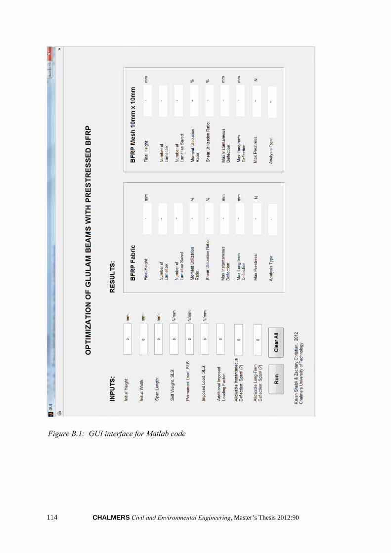
114 CHALMERS Civil and Environmental Engineering, Master’s Thesis 2012:90
Figure B.1: GUI interface for Matlab code