Embed Size (px)
Citation preview
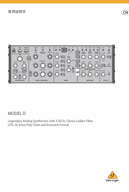
MODEL D
Legendary Analog Synthesizer with 3 VCOs, Classic Ladder Filter, LFO, 16-Voice Poly Chain and Eurorack Format
重要的安全须知
¼'' TS
1. 2. 3. 4.
5.
6. 7.
8.
9.
10.
11.
12.
13.
14.
15.
16.
17. 2000
MUSIC Tribe
MIDAS, KLARK TEKNIK, LAB GRUPPEN, LAKE, TANNOY, TURBOSOUND, TC ELECTRONIC, TC HELICON, BEHRINGER, BUGERA COOLAUDIO
MUSIC Tribe Global Brands Ltd.
© MUSIC Tribe Global Brands Ltd. 2018
musictri.be/warranty
法律声明
保修条款
2 3快速启动向导MODEL D
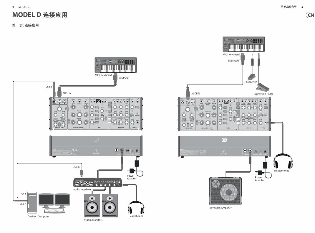
第一步: 连接应用
MODEL D 连接应用
Desktop Computer
MIDI Keyboard
HeadphonesStudio Monitors
Audio Interface
USB B
MIDI IN
MIDI OUT
USB B
USB A
USB A
PowerAdaptor
Headphones
PowerAdaptor
Expression Pedal
Footswitch
MIDI Keyboard
MIDI OUT
MIDI IN
Keyboard Amplifier
4 5快速启动向导MODEL D
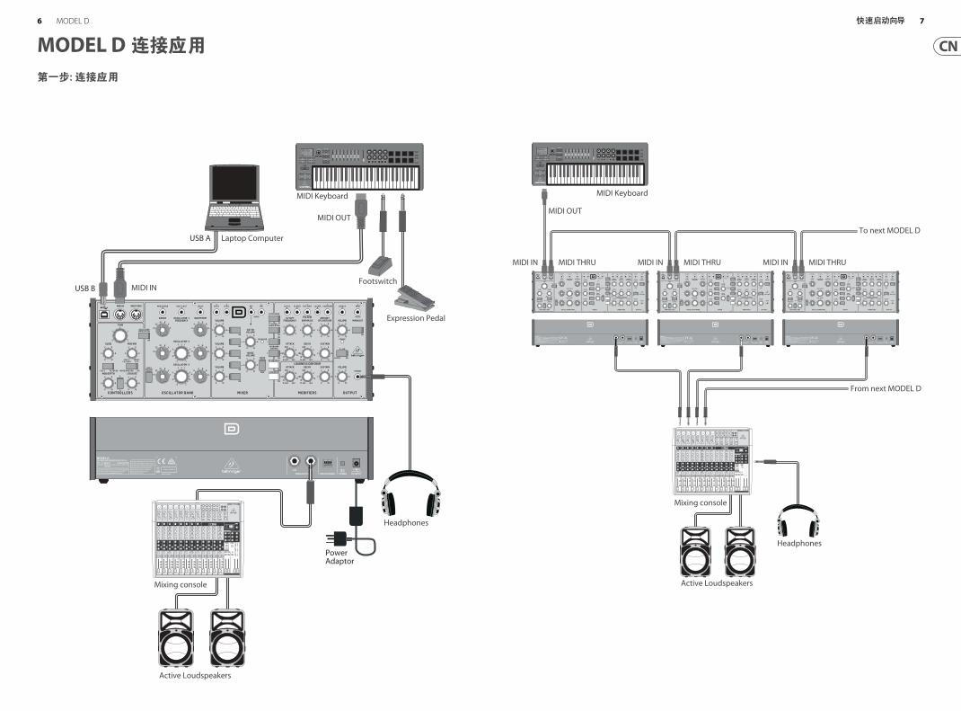
第一步: 连接应用
MODEL D 连接应用
Expression Pedal
Footswitch
Headphones
PowerAdaptor
MIDI Keyboard
MIDI OUT
Mixing console
Active Loudspeakers
Laptop Computer
USB B
USB A
MIDI IN
MIDI IN MIDI THRU MIDI IN MIDI THRU MIDI IN MIDI THRU
To next MODEL D
From next MODEL D
MIDI Keyboard
MIDI OUT
Mixing console
Active Loudspeakers
Headphones
6 7快速启动向导MODEL D
MODEL D 控制
第二步: 控制
(1)
(6) (7)
(36) (47)
(46)
(35)
(34)
(8)
(9)
(5)
(33)
(32) (44)
(42)
(45)
(43)(31)
(30)
(4)
(2) (3) (17)
(10) (11) (12) (13) (14) (15) (16) (20) (21) (22)
(24)
(25)
(23)
(18) (26) (27)
(37) (38) (39) (40) (41) (48) (49)
(28) (29)(19)
(51)(50)
1 2 3 4
5 6 7 8
9 10 11 12
13 14 15 16
(52) (53)
8 9快速启动向导MODEL D
MODEL D 控制
第二步: 控制
部分
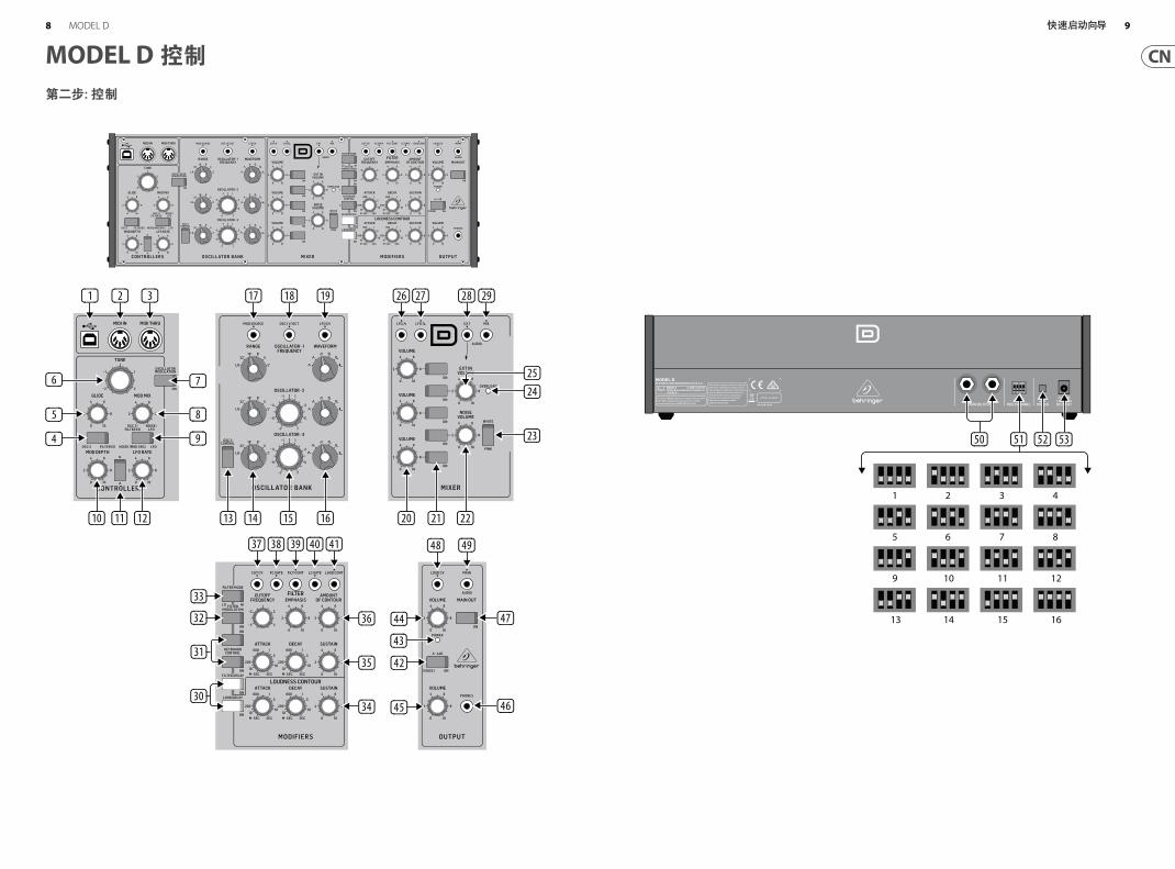
(1) USB PORT – 此 USB B 类型接口可连接电脑。 MODEL D 将会显示为类兼容 USB MIDI 设备, 能够支持 MIDI 输入和输出。
USB MIDI IN – 接收应用程序输入的 MIDI 数据。
USB MIDI OUT – 发送 MIDI 数据到一个应用程序。
(2) MIDI IN – 此 5-pin DIN 接口接收外部源的 MIDI 数据。 外部源通常为 MIDI 键盘, 外部硬件音序器, 配有 MIDI 接口的电脑等。
(3) MIDI THRU – 此 5-pin DIN 接口用于送出从 MIDI INPUT 接收的 MIDI 数据。 这个通常被发送到另一个 MODEL D 合成器来运行 Poly Chain 或分配到不同的 MIDI 通道的鼓机。
控制器部分
(4) OSC3/FILTER EG – 切换选择 OSC 3 或 FILTER EG (滤波器包络) 作为调制源。
(5) GLIDE – 调节键盘的音符之间的 Glide (滑音) 量。
(6) TUNE – 调节振荡器 1, 2 或 3 的频率。 (如果 OSC3 CONTROL 开关关闭, 那么 OSC3 不受影响。)
(7) OSCILLATOR MODULATION – 当开启时, 三个振荡器由调制混音调制, 由 MOD MIX 旋钮设置。
(8) MOD MIX – 调节 OSC3/FILTER EG 和 NOISE/LFO 之间的调制混音。
(9) NOISE (MOD SRC)/ LFO – 切换选择 NOISE (或外部调制源) 或低频振荡器 (LFO) 作为调制源。
(10) MOD DEPTH – 调节调制深度从 OFF 到最大。 也可使用 MIDI 键盘上的调制轮调节调制深度。
(11) WAVE SHAPE – 选择 LFO 波形为三角形或方波。
(12) LFO RATE – 调节低频振荡器 (LFO) 的频率。
振荡器库部分
(13) OSC 3 CONTROL – 当开启时, Oscillator 3 的频率随着键盘而变化。 当关闭时, 键盘、音高轮和调制轮对 OSC3 不起作用。
(14) FREQUENCY RANGE – 从 Oscillator 1, 2 或 3 的六个频率范围中选择。
(15) FREQUENCY ADJUSTMENT – 调节 Oscillator 2 或 3 的频率。
(16) WAVE SHAPE – 选择用于 Oscillator 1, 2 或 3 的波形, 包括: 三角形, 三角形/锯齿波 (Osc 1 和 2), 反向锯齿波 (Osc 3), 锯齿波, 方波, 中型脉冲和窄脉冲。
(17) MOD SOURCE (INPUT) – 可连接一个外部调制源。 如果这里不连接任何源, 那么内部噪声发生器可用作调制源。
(18) OSC 1V/OCT (INPUT) – 此输入端允许通过外部控制电压来调节三个振荡器的频率 (每增加 1 Volt 的输入, 频率会增加1个八度)。
(19) LFO CV (INPUT) – 允许通过外部控制电压来控制 LFO 频率。
混音器部分
(20) VOLUME – 调节 Oscillator 1, 2 或 3 的音量。
(21) ON/OFF – 选择播放的源, 包括 Osc 1, Osc 2, Osc 3, 噪声, 外部输入信号, 或任意这五种源的混合。
(22) NOISE VOLUME – 调节内部噪声源的电平。
(23) WHITE/PINK – 切换选择内部噪声源为粉红噪声或白噪声。
(24) OVERLOAD – 当混音的音频电平过载混音器部分时亮。
(25) EXT IN VOLUME – 调节输入到外部输入端的外部源的电平。 如果没有任源连接到外部输入端, 那么此时没有任何外部音源, 主 MODEL D 输出信号将自动连接到这里。
这将创建一个从输出返回到混音器部分的反馈路径, 以获得额外的宽低音和效果。 在这种情况下, EXT IN 音量旋钮调节输入的主音频发送到混音器部分的信号的电平。
(26) LFO Triangular (OUTPUT) – 输出内部 LFO 三角波信号。
(27) LFO Square (OUTPUT) – 输出内部 LFO 方波信号。
(28) EXT (INPUT) – 连接外部线路电平音频源到此 3.5 mm 输入端。 如果这里没有连接任何源, 那么主音频输出端内部连接到这个外部输入端。
(29) MIX (OUTPUT) – 从这个混音器部分输出最后的混音。
调节器部分
(30) DECAY – 当开启时, 信号会在一个音符或外触发器释放后, 在 DECAY TIME 旋钮设定的时间内衰减。 当关闭时,它会立即衰减。 它会在音符或外触发器释放后立即衰减。
LOUDNESS DECAY – 影响响度部分音量电平的衰减。
FILTER DECAY – 影响滤波器部分截止频率的衰减。
(31) KEYBOARD CONTROL – 这些开关改变键盘跟踪效果, 在这里滤波器部分会受弹奏音符音高的影响。
开关 1 和 2 关闭 – 没有键盘跟踪效果
开关 1 和 2 打开 – 最大效果
只有开关 1 打开 – 最大效果的 1⁄3
只有开关 2 打开 – 最大效果的 2⁄3
(32) FILTER MODULATION – 当开启时, 滤波器部分由调制混音调制, 由 MOD MIX 旋钮设置。
(33) FILTER MODE – 选择低通或高通滤波器。
(34) LOUDNESS CONTOUR – 这三个旋钮调节在通过混音器部分和滤波器部分后音频的整体形状包络。 控制旋钮可随着时间影响音量 (响度) 电平的变化。
ATTACK – 调节在一个音符弹奏后, 信号达到最大电平所需的时间。
DECAY TIME – 调节在起音时间结束后, 信号衰减到持续音量电平的时间。 如果 LOUDNESS DECAY 开关开启, 这个也是当一个音符被释放后, 衰减到最小的时间。
SUSTAIN – 调节在起音时间和初始衰减时间已经达到后信号持续的音量电平。
(35) FILTER ENVELOPE CONTROLS – 这 3 个旋钮调节滤波器部分整体形状包络。 这些控制旋钮随着时间影响截止频率的变化。
ATTACK – 调节截止频率从它的设定值增加并达到由 AMOUNT OF CONTOUR 控制旋钮设定的频率的时间。
DECAY TIME – 调节在起音时间结束后, 截止频率衰减到持续频率的时间。 如果 FILTER DECAY 开关开启, 那么这个衰减时间也是当一个音符释放后, 从持续频率衰减的时间。
SUSTAIN – 调节在起音时间和初始衰减时间已经达到后持续的截止频率。
(36) FILTER CONTROLS – 滤波器可以为低通或高通, 取决于 FILTER MODE 开关的设置。 在低通模式, 高于截止频率的音频被衰减。 在高通模式, 低于截止频率的音频被衰减。
CUTOFF FREQUENCY – 调节滤波器的截止频率。
FILTER EMPHASIS – 调节在截止频率下音量电平提升 (谐振) 的量。
AMOUNT OF CONTOUR – 调节截止频率的频率偏移量。
(37) CUT CV (INPUT) – 可连接控制电压来控制截止频率。
(38) FC GATE (INPUT) – 允许外部触发器电压用于触发滤波器曲线。
(39) FILT CONT (OUTPUT) – 输出滤波器曲线。
(40) LC GATE (INPUT) –允许外触发器电压用于触发等响曲线。
(41) LOUD CONTOUR (OUTPUT) – 输出等响曲线。
Output Section 输出部分
(42) A-440 – 使用这个打开一个 440 Hz 音乐会音高的输出调谐信号。 此开关也可用于在开机时进入各种模式 (参见此说明书的快速启动部分获取详细信息)。
(43) POWER – 接通电源且合成器开启时, 此 LED 灯亮。
(44) VOLUME – 调节合成器输出总的音量电平。
(45) VOLUME (HEADPHONE) – 调节 PHONES 输出总的音量电平。
10 11快速启动向导MODEL D
(46) PHONES – 连接你的耳机到此 3.5 mm TRS 输出端。 在戴上耳机前请确保耳机音量调小。
(47) ON – 使用这个快速将合成器的主音频输出信号打开或静音。
(48) LOUD CV (INPUT) – 可连接外部控制电压来控制等响曲线。
(49) MAIN (OUTPUT) – 使用此 3.5 mm TRS 连接来输出主音频输出信号。 通常它被分配到 MODEL D 的音频输入端或其它模块化合成器设备的音频输入端。 如果你在 Eurorack 里使用 MODEL D, 那么这个是主输出端, 因为后面板输出接口没有被使用。
后面板
(50) MAIN OUTPUT – 连接这些 ¼" TRS 输出端到外部设备的输入端 (注意他们均为单声道, 而不是左/右):
LOW – 此乐器电平单声道输出端可连接吉他功放或调音台的乐器电平输入端。
HIGH – 此线路电平单声道输出端可连接调音台, 键盘放大器或有源音箱的线路电平输入端。
(51) MIDI CHANNEL – 这 4 个开关可用于设置从 1 到 16 的MIDI通道数 (参见第 15 页的表格)。 MIDI 通道也可使用 MIDI SysEx 命令更改, 如说明书后面的 MIDI SysEx 表所示。 当将 MODEL D 放在 Eurorack 支架时, 使用这种方法, 且这些开关不再出现。
(52) POWER – 打开或关闭合成器。 在打开设备之前, 请确保所有的连接完成。
(53) DC INPUT – 在此连接随货供应的 12V DC 电源适配器。 电源适配器可插入 AC 插座, 此插座能供应 50 Hz/60 Hz 的频率, 100 V 到 240 V 的电压。 只可使用随货供应的电源适配器。
12 13快速启动向导MODEL D
MODEL D 使用
第三步: 使用
概述
此 “快速启动” 指南可帮助你设置 MODEL D 模拟合成器并简单绍了它的功能。
连接
想连接 MODEL D 到你的系统, 请先参阅本文档前面的连接指南。 注意: 请勿过载 3.5 mm 输入端。 他们只能接收如技术参数表所示的正确电压水平。 3.5 mm 输出端只能连接能够接收输出电压的输入端。 如果不遵照这些指示可能会损坏 MODEL D 或外部设备。
软件安装
MODEL D 为 USB 类兼容 MIDI 设备, 因此不需要安装驱动程序。 MODEL D 不需任何额外的驱动程序来同 Windows 和 MacOS 一起工作。
硬件安装
完成系统中的所有连接。 使用后面板 MIDI 开关将 MODEL D 设置成系统中唯一的 MIDI 通道。 将外部 MIDI 键盘直接连接到 MODEL D MIDI IN 5-pin DIN 类型的输入端。 只可使用随货供应的电源适配器接通 MODEL D 的电源。 请确保你的声音系统关闭。 打开 MODEL D 后面板的电源开关。
预热时间
我们建议在录音或现场表演前, 留出 15 分钟或更多的时间给 MODEL D 预热。 (如果从寒冷中带进来, 时间更长。) 这将使精密模拟电路的时间达到正常工作温度和调优性能。
初始化设置
一个快速发现外部音响系统是否工作的方法是打开 MODEL D 的 A-440 开关并调节音量控制。 这会发送固定的频率输出 (440 Hz) 到外部功放和音箱。
混音器部分
MODEL D 设有三个振荡器, 一个内置噪声发生器和一个外部源输入端。 这些中的一个和任意混合都被 MODEL D 用来生成声音。
混音器部分可使你打开或关闭这些源, 且调节每个源的音量来创建一个总混音。 首先打开用于振荡器1的顶部开关, 并关闭其它开关。 调节振荡器1的音量控制旋钮。 在输出部分, 调节主音量。 现在, 如果你弹奏 MIDI 键盘上的一个音符, 你应该只听到振荡器1的声音。 打开其它振荡器和/或噪声并调节他们的音量控制旋钮来创建一个混音。
振荡器部分
在振荡器部分, 调节 RANGE 旋钮, 你会听到各种八度音的声音。 调节波形并听取差异。 振荡器调制开关允许振荡器频率由调制混音调制。 OSC 3 开关允许它的频率受键盘上弹奏的音符, 调制和音高轮的影响, 或不受影响。注意: TONE 旋钮, OSCILLATOR-2 和- 3 FREQUENCY 旋钮以半音为单位标记,作为通用指南。
滤波器部分
尝试调节 CUTOFF FREUQENCY、 EMPHASIS 和 AMOUNT OF CONTOUR 旋钮, 并倾听他们在声音上的效果。 调节 ATTACK, DECAY 和SUSTAIN。 当弹奏一个音符时, 它们会随着时间影响截止频率。滤波器衰减开关在一个音符释
放后影响衰减。 2 个键盘开关影响滤波器受弹奏音符频率的影响有多大。 如果滤波器调制开关开启, 那么滤波器部分由调制混音调制。
等响曲线部分
在这个部分, 调节 ATTACK, DECAY 和 SUSTAIN。 当一个音符被弹奏时, 它们会随着时间影响总的电平。 响度衰减开关在音符被释放后影响电平衰减。
控制器部分
首先设置 2 个开关选择内部 LFO 或内部噪声、 OSC 3 或滤波器包络, 然后使用 MOD MIX 旋钮改变它们之间的混音。 你可尝试先设置开关到 OSC 3, 然后旋转 MOD MIX 旋钮到 OSC 3。 然后设置振荡器 3 的 RANGE 控制旋钮到 LO, 及振荡器调制开关到 ON。 现在你可以听到由 OSC 3 调制的振荡器 1 的声音。 使用 MOD DEPTH 旋钮, 和/或键盘的调制轮来增加效果。 如果滤波器调制开关开启, 倾听滤波器上调制效果。
调制灵敏度曲线可从 hard, medium 或 soft (默认) 中选择, 使用说明书后面显示的 SysEx 命令。
特殊模式
A-440 开关可用于将 MODEL D 设置成各种操作模式。 这是通过在开启 MODEL D 电源的前 5 秒内将 A-44 开关打开和关闭一定的次数来完成的。 次数决定模式, 如下表所示。 电源指示灯会闪烁显示当前值。
多触发器
Multi-triggering - ON: 弹奏一个新的音符会改变音高, 也会触发滤波器和等响曲线包络。
Multi-triggering – OFF (默认, 连音): 弹奏新的音符改变音高, 但除非所有的音符都被释放, 否则不会有新的触发。 比如, 你可弹奏一个音符并把它按下, 新的音符会弹奏并使用按下音符的包络。 第二个音符经常会在按下音符的起音时间和衰减时间过去后弹奏, 因此第二个音符不会有起音和衰减通常会发出的声音。
音符优先级
Note Priority – 如果同时弹奏多个音符, 这个设置哪个音符有优先权: 最后一个弹奏的音符, 最低 (默认), 或最高。
POLY CHAINPoly Chain – 如果你有多个 MODEL D 设备, 你可将它们连接在一个 Poly Chain 上, 这样第一个 MODEL D 播放最低的音符, 第二个 MODEL D 播放第二最低的音符, 以此类推来产生复音。 每个 MODEL D 必须使用后面板
开关设置相同的 MIDI 通道号。 Poly Chain 连接如第 7 页的图表所示。 仅设置第一个 MODEL D 的 Poly Chain 到 ON 的位置。 完成后将其关闭。 如果你仅使用一个 MODEL D, 那么请确保 Poly Chain 处于 OFF 的位置。
EURORACKMODEL D合成器可从它的工厂底架中取出来并装入标准的 Eurorack 箱中(不随货供应)。 请参阅本说明书后面的详细信息。
固件更新
请定期检查我们的网站 behringer.com, 查看 MODEL D 合成器的固件是否需要更新。 固件文件可下载并储存到你的电脑, 然后用于更新 MODEL D。 它附带了更新过程的详细说明。
玩得开心
MODEL D 设有各种 Gate 和 CV 输入端和输出端, 允许进一步的实验和扩展到其它 MODEL D 设备和模块化合成器设备。 MODEL D 的 SysEx 功能允许你设置和调节各种参数以适合你喜好的。 请参见此说明书后面的 SysEx 信息。 复制此说明书后面的分配表, 并记录您最喜欢的设置。 有了这些控制, 音乐创作的可能性是无止境的, 就像有了一盒新的颜料的艺术家。
我们希望你会喜欢你的新 MODEL D。
按下 A-440 开关
模式 电源指示灯闪烁
开和关 多触发器 ON
快速闪烁两次
多触发器 OFF
缓慢闪烁两次
开和关和开
音符优先级
LAST/LOW/
HIGH
闪烁三次
开和关, 开和关
Poly Chain
ON
快速闪烁四次
Poly Chain
OFF
缓慢闪烁四次
14 15快速启动向导MODEL D
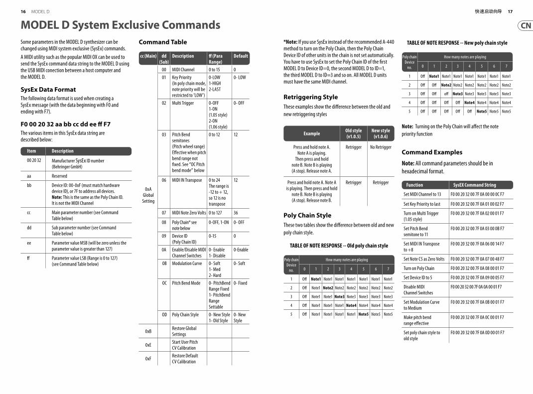
MODEL D System Exclusive CommandsSome parameters in the MODEL D synthesizer can be changed using MIDI system exclusive (SysEx) commands.
A MIDI utility such as the popular MIDI OX can be used to send the SysEx command data string to the MODEL D using the USB MIDI conection between a host computer and the MODEL D.
SysEx Data FormatThe following data format is used when creating a SysEx message (with the data beginning with F0 and ending with F7).
F0 00 20 32 aa bb cc dd ee ff F7The various items in this SysEx data string are described below:
Item Description
00 20 32 Manufacturer SysEx ID number
(Behringer GmbH)
aa Reserved
bb Device ID: 00-0xF (must match hardware
device ID), or 7F to address all devices.
Note: This is the same as the Poly Chain ID.
It is not the MIDI Channel
cc Main parameter number (see Command
Table below)
dd Sub parameter number (see Command
Table below)
ee Parameter value MSB (will be zero unless the
parameter value is greater than 127)
ff Parameter value LSB (Range is 0 to 127)
(see Command Table below)
Command Table *Note: If you use SysEx instead of the recommended A-440 method to turn on the Poly Chain, then the Poly Chain Device ID of other units in the chain is not set automatically. You have to use SysEx to set the Poly Chain ID of the fi rst MODEL D to Device ID=0, the second MODEL D to ID=1, the third MODEL D to ID=3 and so on. All MODEL D units must have the same MIDI channel.
Retriggering StyleThese examples show the diff erence between the old and
new retriggering styles
Example Old style (v1.0.5)
New style (v1.0.6)
Press and hold note A.
Note A is playing.
Then press and hold
note B. Note B is playing
(A stop). Release note A.
Retrigger No Retrigger
Press and hold note A. Note A
is playing. Then press and hold
note B. Note B is playing
(A stop). Release note B.
Retrigger Retrigger
Poly Chain StyleThese two tables show the diff erence between old and new
poly chain style.
TABLE OF NOTE RESPONSE -- Old poly chain style
Poly chain
Device
no.
How many notes are playing
0 1 2 3 4 5 6 7
1 Off Note1 Note1 Note1 Note1 Note1 Note1 Note1
2 Off Note1 Note2 Note2 Note2 Note2 Note2 Note2
3 Off Note1 Note1 Note3 Note3 Note3 Note3 Note3
4 Off Note1 Note1 Note1 Note4 Note4 Note4 Note4
5 Off Note1 Note1 Note1 Note1 Note5 Note5 Note5
TABLE OF NOTE RESPONSE -- New poly chain style
Note: Turning on the Poly Chain will aff ect the note
priority function
Command Examples
Note: All command parameters should be in
hexadecimal format.
Poly chain
Device
no.
How many notes are playing
0 1 2 3 4 5 6 7
1 Off Note1 Note1 Note1 Note1 Note1 Note1 Note1
2 Off Off Note2 Note2 Note2 Note2 Note2 Note2
3 Off Off off Note3 Note3 Note3 Note3 Note3
4 Off Off Off Off Note4 Note4 Note4 Note4
5 Off Off Off Off Off Note5 Note5 Note5
Function SysEX Command String
Set MIDI Channel to 13 F0 00 20 32 00 7F 0A 00 00 0C F7
Set Key Priority to last F0 00 20 32 00 7F 0A 01 00 02 F7
Turn on Multi Trigger
(1.05 style)
F0 00 20 32 00 7F 0A 02 00 01 F7
Set Pitch B end
semitone to 11
F0 00 20 32 00 7F 0A 03 00 0B F7
Set MIDI IN Transpose
to +8
F0 00 20 32 00 7F 0A 06 00 14 F7
Set Note C5 as Zero Volts F0 00 20 32 00 7F 0A 07 00 48 F7
Turn on Poly Chain F0 00 20 32 00 7F 0A 08 00 01 F7
Set Device ID to 5 F0 00 20 32 00 7F 0A 09 00 05 F7
Disable MIDI
Channel Switches
F0 00 20 32 00 7F 0A 0A 00 01 F7
Set Modulation Curve
to Medium
F0 00 20 32 00 7F 0A 0B 00 01 F7
Make pitch bend
range eff ective
F0 00 20 32 00 7F 0A 0C 00 01 F7
Set poly chain style to
old style
F0 00 20 32 00 7F 0A 0D 00 01 F7
cc (Main) dd (Sub)
Description ff (Para Range)
Default
0xA
Global
Setting
00 MIDI Channel 0 to 15 0
01 Key Priority
(In poly chain mode,
note priority will be
restricted to ’LOW’)
0-LOW
1-HIGH
2-LAST
0- LOW
02 Multi Trigger 0-OFF
1-ON
(1.05 style)
2-ON
(1.06 style)
0- OFF
03 Pitch Bend
semitones
(Pitch wheel range)
Eff ective when pitch
bend range not
fi xed. See “OC Pitch
bend mode” below
0 to 12 12
06 MIDI IN Transpose 0 to 24
The range is
-12 to + 12,
so 12 is no
transpose
12
07 MIDI Note Zero Volts 0 to 127 36
08 Poly Chain* see
note below
0-OFF, 1-ON 0- OFF
09 Device ID
(Poly Chain ID)
0-15 0
0A Enable/Disable MIDI
Channel Switches
0- Enable
1- Disable
0-Enable
0B Modulation Curve 0- Soft
1- Med
2- Hard
0- Soft
OC Pitch Bend Mode 0- PitchBend
Range Fixed
1- PitchBend
Range
Settable
0- Fixed
OD Poly Chain Style 0- New Style
1- Old Style
0- New
Style
0xBRestore Global
Settings
0xEStart User Pitch
CV Calibration
0xFRestore Default
CV Calibration
16 17快速启动向导MODEL D
MO
DEL
D P
atch
She
etPa
tch
Num
ber
DAT
E:
NO
TES:
AUTH
OR:
TITL
E:
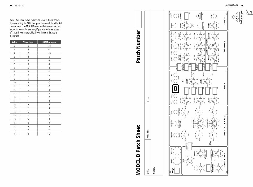
Note: A decimal to hex conversion table is shown below. If you are using the MIDI Transpose command, then the 3rd column shows the MIDI IN Transpose that corresponds to each data value. For example, if you wanted a transpose of +8 as shown in the table above, then the data sent is 14 (hex).
Value Value (hex) MIDI Transpose0 0 -12
1 1 -11
2 2 -10
3 3 -9
4 4 -8
5 5 -7
6 6 -6
7 7 -5
8 8 -4
9 9 -3
10 A -2
11 B -1
12 C 0
13 D 1
14 E 2
15 F 3
16 10 4
17 11 5
18 12 6
19 13 7
20 14 8
21 15 9
22 16 10
23 17 11
24 18 12
18 19快速启动向导MODEL D
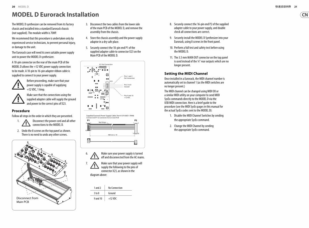
MODEL D Eurorack InstallationThe MODEL D synthesizer can be removed from its factory
chassis and installed into a standard Eurorack chassis
(not supplied). The module width is 70HP.
We recommend that this procedure is undertaken only by
experienced service technicians, to prevent personal injury,
or damage to the unit.
The Eurorack case will need its own suitable power supply
unit to power the MODEL D synthesizer.
A 10-pin connector on the rear of the main PCB of the
MODEL D allows the +12 VDC power supply connection
to be made. A 10-pin to 16-pin adapter ribbon cable is
supplied to connect to your power supply.
Before proceeding, make sure that your
power supply is capable of supplying
+12 VDC, 1 Amp.
Make sure that the connections using the
supplied adapter cable will supply the ground
and power to the correct pins of X23.
ProcedureFollow all steps in the order in which they are presented.
1. Disconnect the power cord and all other connections to the MODEL D.
2. Undo the 8 screws on the top panel as shown. There is no need to undo any other screws.
3. Disconnect the two cables from the lower side of the main PCB of the MODEL D, and remove the assembly from the chassis.
4. Store the chassis assembly and the power supply adaptor in a dry safe place.
5. Securely connect the 10-pin end P1 of the supplied adapter cable to connector X23 on the Main PCB of the MODEL D.
6. Make sure your power supply is turned off and disconnected from the AC mains.
7. Make sure that your power supply will supply the following to the pins of connector X23, as shown in the
diagram above:
Pins Connection
1 and 2 No Connection
3 to 8 Ground
9 and 10 +12 VDCDisconnect fromMain PCB
400 mm ± 10
12
910
1
15
2
16
Red Stripe
Supplied Eurorack Power Supply Cable, Part # A74-0001-79446Connect End P1 to Connector X23 on main PCB
Pins 1 and 2No Connection
X23
X21 No Connection
Pins 3 to 8Ground
Pins 9 and 10+12 VDC
P1 P2
8. Securely connect the 16-pin end P2 of the supplied adapter cable to your power supply, and double check all connections are correct.
9. Securely install the MODEL D Synthesizer into your Eurorack, using 8 screws in the front panel.
10. Perform a full test and safety test before using the MODEL D.
11. The 3.5 mm MAIN OUT connector on the top panel is used instead of the ¼" rear outputs which are no longer present.
Setting the MIDI ChannelOnce installed in a Eurorack, the MIDI channel number is automatically set to channel 1 (as the MIDI switches are no longer present.)
The MIDI channel can be changed using MIDI OX or a similar MIDI utility on your computer to send MIDI SysEx commands directly to the MODEL D via the USB MIDI connection. Here is a brief guide to the procedure (see the MIDI SysEx pages in this manual for the actual SysEx codes sent to the MODEL D):
1. Disable the MIDI Channel Switches by sending
the appropriate SysEx command.
2. Change the MIDI Channel by sending the appropriate SysEx command.
20 21快速启动向导MODEL D
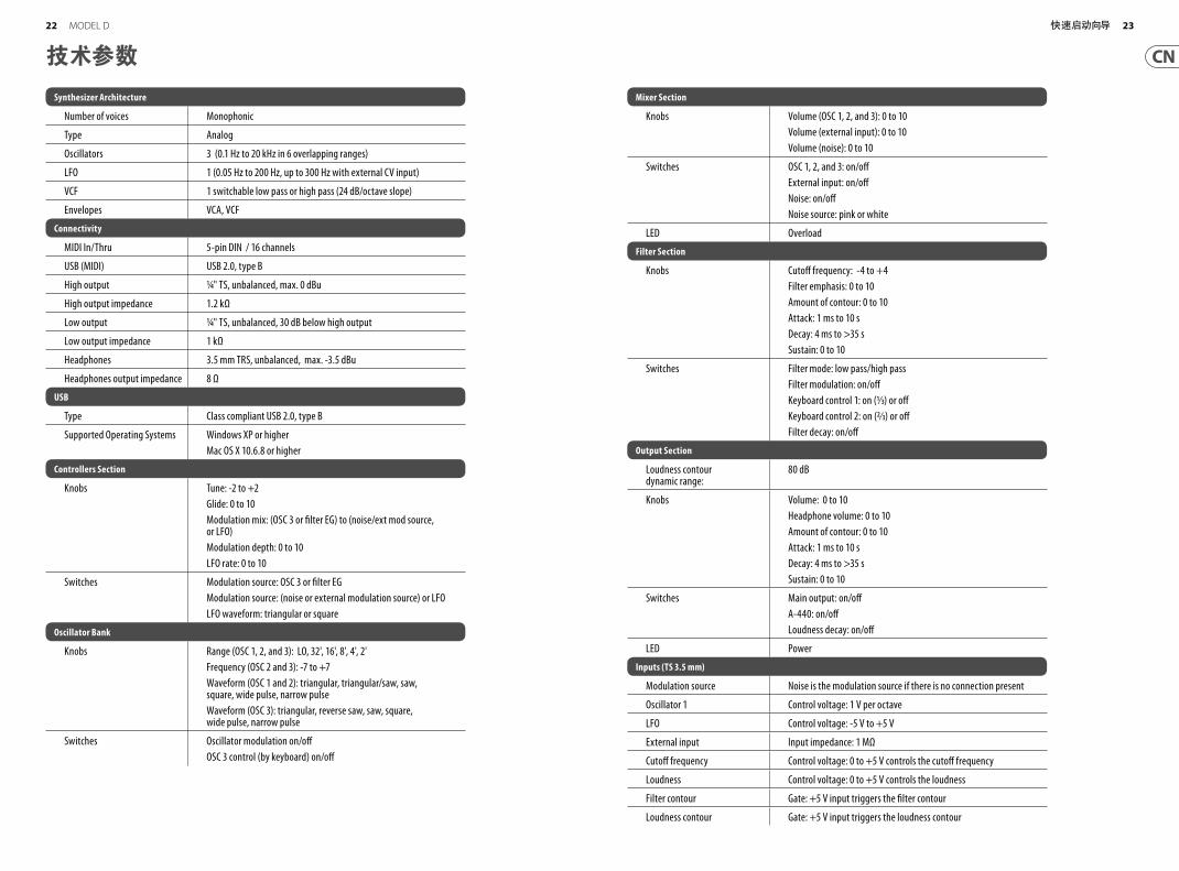
技术参数
Synthesizer Architecture
Number of voices Monophonic
Type Analog
Oscillators 3 (0.1 Hz to 20 kHz in 6 overlapping ranges)
LFO 1 (0.05 Hz to 200 Hz, up to 300 Hz with external CV input)
VCF 1 switchable low pass or high pass (24 dB/octave slope)
Envelopes VCA, VCF
Connectivity
MIDI In/Thru 5-pin DIN / 16 channels
USB (MIDI) USB 2.0, type B
High output ¼ " TS, unbalanced, max. 0 dBu
High output impedance 1.2 kΩ
Low output ¼ " TS, unbalanced, 30 dB below high output
Low output impedance 1 kΩ
Headphones 3.5 mm TRS, unbalanced, max. -3.5 dBu
Headphones output impedance 8 Ω
USB
Type Class compliant USB 2.0, type B
Supported Operating Systems Windows XP or higher
Mac OS X 10.6.8 or higher
Controllers Section
Knobs Tune: -2 to +2
Glide: 0 to 10
Modulation mix: (OSC 3 or fi lter EG) to (noise/ext mod source, or LFO)
Modulation depth: 0 to 10
LFO rate: 0 to 10
Switches Modulation source: OSC 3 or fi lter EG
Modulation source: (noise or external modulation source) or LFO
LFO waveform: triangular or square
Oscillator Bank
Knobs Range (OSC 1, 2, and 3): LO, 32', 16', 8', 4', 2'
Frequency (OSC 2 and 3): -7 to +7
Waveform (OSC 1 and 2): triangular, triangular/saw, saw, square, wide pulse, narrow pulse
Waveform (OSC 3): triangular, reverse saw, saw, square, wide pulse, narrow pulse
Switches Oscillator modulation on/off
OSC 3 control (by keyboard) on/off
Mixer Section
Knobs Volume (OSC 1, 2, and 3): 0 to 10
Volume (external input): 0 to 10
Volume (noise): 0 to 10
Switches OSC 1, 2, and 3: on/off
External input: on/off
Noise: on/off
Noise source: pink or white
LED Overload
Filter Section
Knobs Cutoff frequency: -4 to +4
Filter emphasis: 0 to 10
Amount of contour: 0 to 10
Attack: 1 ms to 10 s
Decay: 4 ms to >35 s
Sustain: 0 to 10
Switches Filter mode: low pass/high pass
Filter modulation: on/off
Keyboard control 1: on (1⁄3) or off
Keyboard control 2: on (2⁄3) or off
Filter decay: on/off
Output Section
Loudness contour dynamic range:
80 dB
Knobs Volume: 0 to 10
Headphone volume: 0 to 10
Amount of contour: 0 to 10
Attack: 1 ms to 10 s
Decay: 4 ms to >35 s
Sustain: 0 to 10
Switches Main output: on/off
A-440: on/off
Loudness decay: on/off
LED Power
Inputs (TS 3.5 mm)
Modulation source Noise is the modulation source if there is no connection present
Oscillator 1 Control voltage: 1 V per octave
LFO Control voltage: -5 V to +5 V
External input Input impedance: 1 MΩ
Cutoff frequency Control voltage: 0 to +5 V controls the cutoff frequency
Loudness Control voltage: 0 to +5 V controls the loudness
Filter contour Gate: +5 V input triggers the fi lter contour
Loudness contour Gate: +5 V input triggers the loudness contour
22 23快速启动向导MODEL D
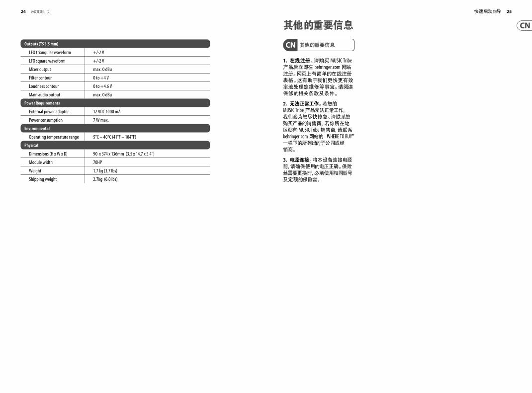
其他的重要信息
1. 在线注册。 请购买 MUSIC Tribe 产品后立即在 behringer. com 网站注册。 网页上有简单的在线注册表格。 这有助于我们更快更有效率地处理您维修等事宜。 请阅读保修的相关条款及条件。
2. 无法正常工作。 若您的 MUSIC Tribe 产品无法正常工作, 我们会为您尽快修复。 请联系您购买产品的销售商。 若你所在地区没有 MUSIC Tribe 销售商, 请联系 behringer. com 网站的 “WHERE TO BUY” 一栏下的所列出的子公司或经销商。
3. 电源连接。 将本设备连接电源前, 请确保使用的电压正确。 保险丝需要更换时, 必须使用相同型号及定额的保险丝。
其他的重要信息Outputs (TS 3.5 mm)
LFO triangular waveform +/-2 V
LFO square waveform +/-2 V
Mixer output max. 0 dBu
Filter contour 0 to +4 V
Loudness contour 0 to +4.6 V
Main audio output max. 0 dBu
Power Requirements
External power adaptor 12 VDC 1000 mA
Power consumption 7 W max.
Environmental
Operating temperature range 5°C – 40°C (41°F – 104°F)
Physical
Dimensions (H x W x D) 90 x 374 x 136mm (3.5 x 14.7 x 5.4")
Module width 70HP
Weight 1.7 kg (3.7 lbs)
Shipping weight 2.7kg (6.0 lbs)
24 25快速启动向导MODEL D

We Hear You


![c û û - ssk-joujima.comssk-joujima.com/dir/30年 大人講座.pdf · Ì û r û û û [ Z Y [ Z [ a \ ^ ] [ û [ [ Y a [ ^ \ [ \ b û. [ Z Y _ [ \ \ ` û [ [ Y \ c ] Z û [ \](https://img.pdfslide.tips/doc/110x75/5bfea57b09d3f2ff098b94bd/c-u-u-ssk-pdf-i-u-r-u-u-u-z-y-z-a-.jpg)


![§6Û+% ` Û / lg § ± ] ` Û /b# C1* · >/>, ó ¡ §6Û+% ` Û / lg § ± ] ` Û /b# C1* » >0>, % $× §6Û+% ` Û / lg § ± ] ` Û /b "@>& "@ Æb0¿ 4Ä'ö ²¡ º'¼v µt>](https://img.pdfslide.tips/doc/110x75/5aecf95f7f8b9ad73f9066d8/6-lg-b-c1-6-lg-b-c1-0-6-lg-b-b0-4.jpg)