Embed Size (px)
Citation preview

FIELD MOUNTEDRATE TOTALISER
MODEL 202D
16 June 2003


Introduction 1
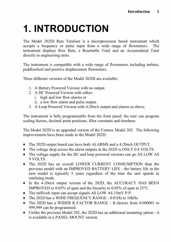
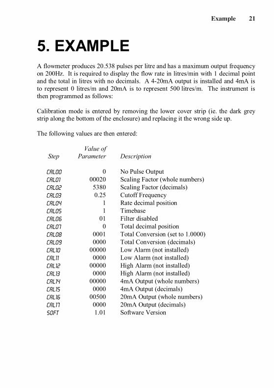
1. INTRODUCTIONThe Model 202Di Rate Totaliser is a microprocessor based instrument whichaccepts a frequency or pulse input from a wide range of flowmeters. Theinstrument displays flow Rate, a Resettable Total and an Accumulated Totaldirectly in engineering units.
The instrument is compatible with a wide range of flowmeters including turbine,paddlewheel and positive displacement flowmeters.
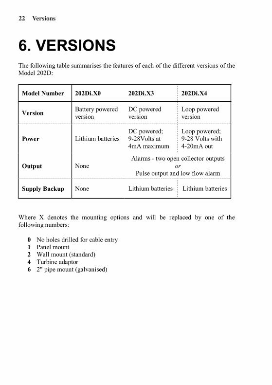
Three different versions of the Model 202Di are available:
1. A Battery Powered Version with no output.2. A DC Powered Version with either:
i. high and low flow alarms orii. a low flow alarm and pulse output.
3. A Loop Powered Version with 4-20mA output and alarms as above.
The instrument is fully programmable from the front panel; the user can programscaling factors, decimal point positions, filter constants and timebase.
The Model 202D is an upgraded version of the Contrec Model 202. The followingimprovements have been made in the Model 202D:
♦ The 202D output board can have both ALARMS and a 4-20mA OUTPUT.♦ The voltage drop across the alarm outputs in the 202D is ONLY 0.8 VOLTS.♦ The voltage supply for the DC and loop powered versions can go AS LOW AS
9 VOLTS.♦ The 202D has an overall LOWER CURRENT CONSUMPTION than the
previous model with an IMPROVED BATTERY LIFE - the battery life in thenew model is typically 5 years regardless of the time the unit spends intotalising mode.
♦ In the 4-20mA output version of the 202D, the ACCURACY HAS BEENIMPROVED to 0.05% of span and the linearity to 0.05% of span at 25°C.
♦ The millivolt input can accept signals AS LOW AS 15mV P-P.♦ The 202D has a WIDE FREQUENCY RANGE - 0.01Hz to 10kHz.♦ The 202D has a WIDER K-FACTOR RANGE - K-factors from 0.000001 to
999,999 can be programmed.♦ Unlike the previous Model 202, the 202D has an additional mounting option - it
is available in a PANEL MOUNT version.

Introduction2
The Model 202Di Rate Totaliser conforms to the EMC-Directive of the Council ofEuropean Communities 89/336/EEC and the following standards:
Generic Emission Standard EN 50081-1 Residential, Commercial & LightIndustry Environment.
Generic Emission Standard EN 50081-2 Industrial Environment.
Generic Immunity Standard EN 50082-1 Residential, Commercial & LightIndustry Environment.
Generic Immunity Standard EN 50082-2 Industrial Environment.
In order to comply with these standards, the wiring instructions in Section 9.5 mustbe adhered to.
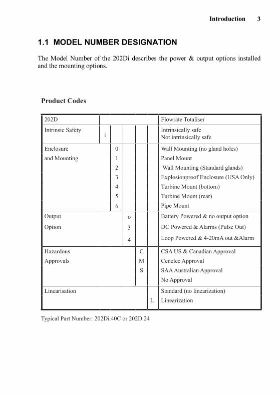
Typical Part Number: 202Di.40C or 202D.24
202D Flowrate Totaliser
Intrinsic Safetyi
Intrinsically safeNot intrinsically safe
Enclosure 0 Wall Mounting (no gland holes)
and Mounting 1 Panel Mount
2 Wall Mounting (Standard glands)
3 Explosionproof Enclosure (USA Only)
4 Turbine Mount (bottom)
5 Turbine Mount (rear)
6 Pipe Mount
Output o Battery Powered & no output option
Option 3 DC Powered & Alarms (Pulse Out)
4 Loop Powered & 4-20mA out &Alarm
Hazardous C CSA US & Canadian Approval
Approvals M Cenelec Approval
S SAA Australian Approval
No Approval
Linearisation Standard (no linearization)
L Linearization
Product Codes
Introduction4
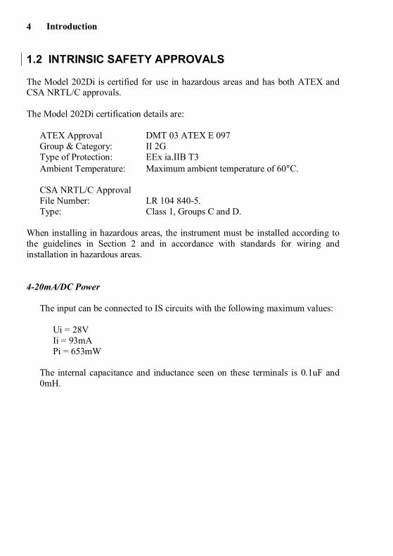
1.2 INTRINSIC SAFETY APPROVALS
The Model 202Di is certified for use in hazardous areas and has both ATEX andCSA NRTL/C approvals.
The Model 202Di certification details are:
ATEX Approval DMT 03 ATEX E 097Group & Category: II 2GType of Protection: EEx ia.IIB T3Ambient Temperature: Maximum ambient temperature of 60°C.
CSA NRTL/C ApprovalFile Number: LR 104 840-5.Type: Class 1, Groups C and D.
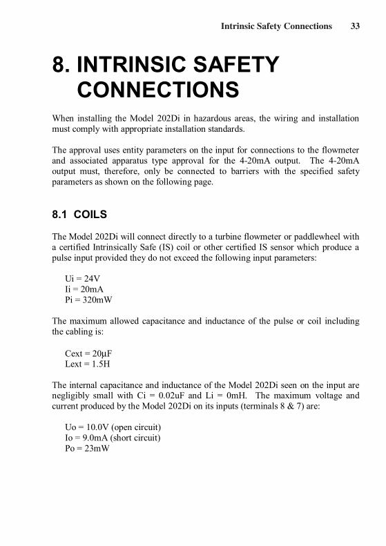
When installing in hazardous areas, the instrument must be installed according tothe guidelines in Section 2 and in accordance with standards for wiring andinstallation in hazardous areas.
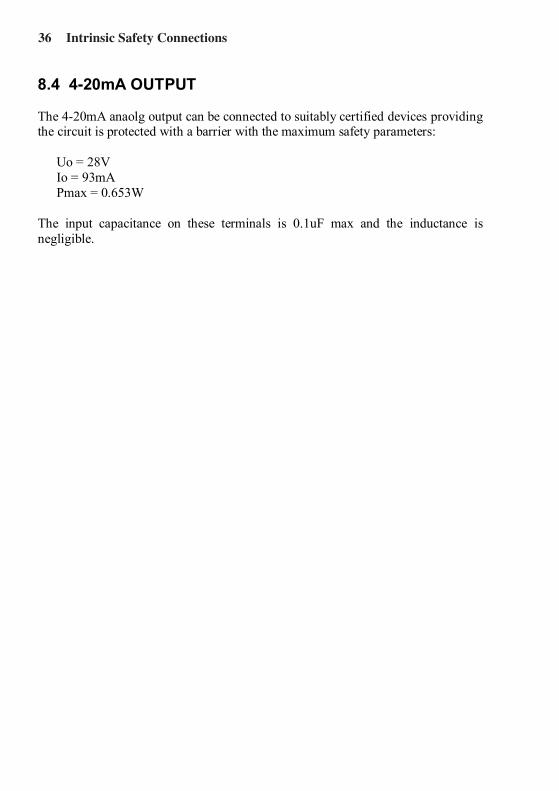
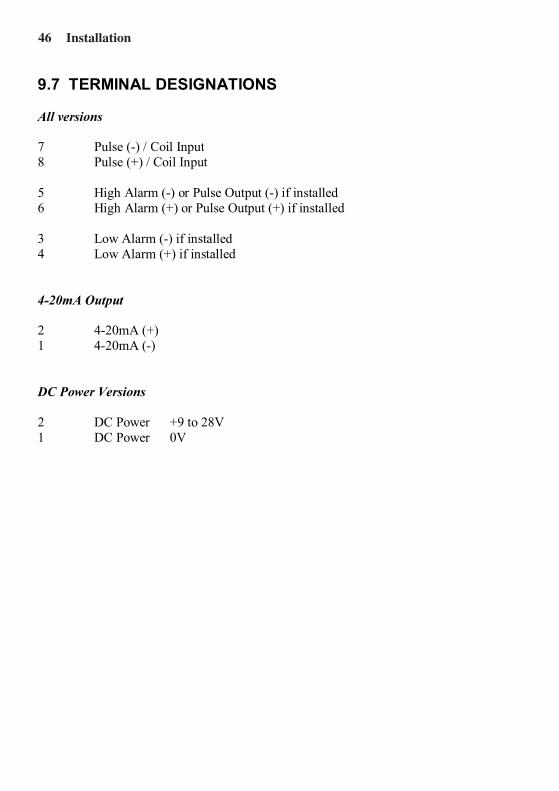
4-20mA/DC Power
The input can be connected to IS circuits with the following maximum values:
Ui = 28VIi = 93mAPi = 653mW
The internal capacitance and inductance seen on these terminals is 0.1uF and0mH.
Introduction 5
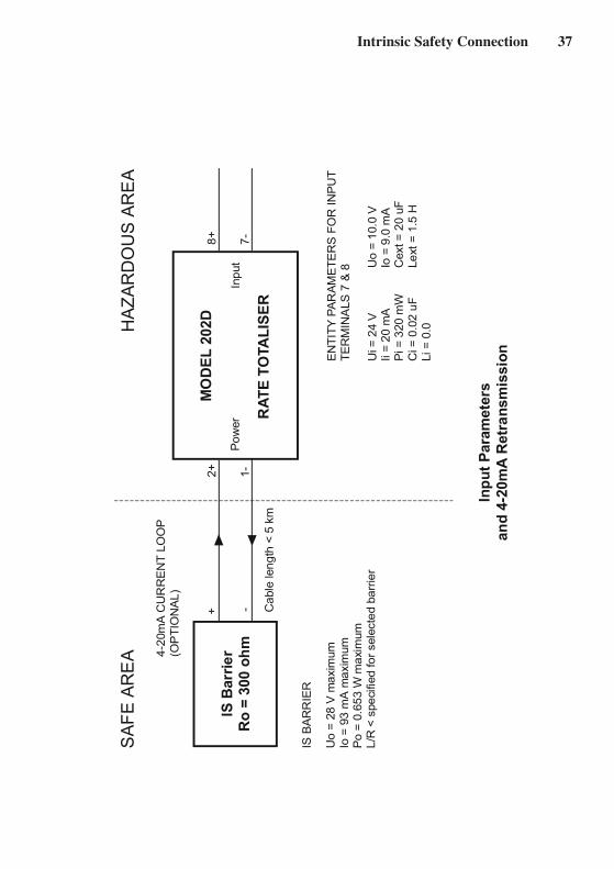
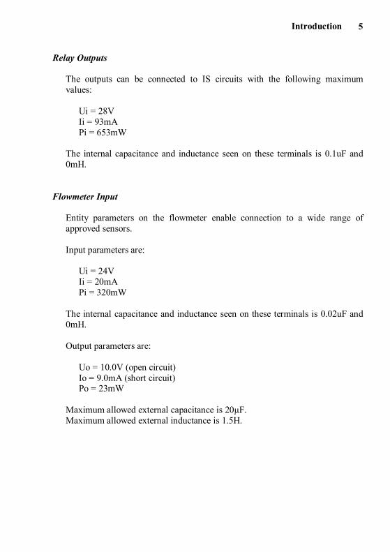
Relay Outputs
The outputs can be connected to IS circuits with the following maximumvalues:
Ui = 28VIi = 93mAPi = 653mW
The internal capacitance and inductance seen on these terminals is 0.1uF and0mH.
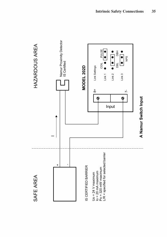
Flowmeter Input
Entity parameters on the flowmeter enable connection to a wide range ofapproved sensors.
Input parameters are:
Ui = 24VIi = 20mAPi = 320mW
The internal capacitance and inductance seen on these terminals is 0.02uF and0mH.
Output parameters are:
Uo = 10.0V (open circuit)Io = 9.0mA (short circuit)Po = 23mW
Maximum allowed external capacitance is 20µF.Maximum allowed external inductance is 1.5H.
Specification6
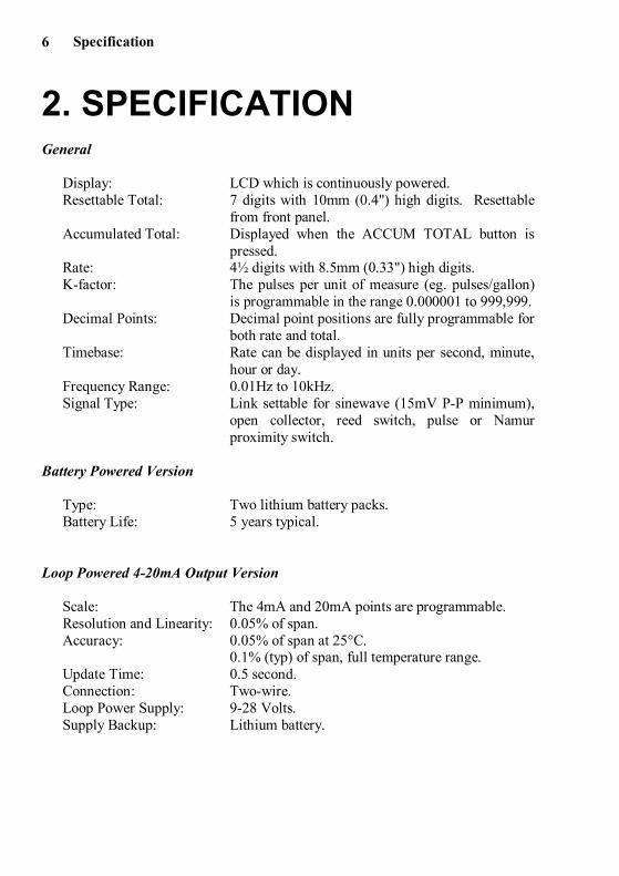
2. SPECIFICATIONGeneral
Display: LCD which is continuously powered.Resettable Total: 7 digits with 10mm (0.4") high digits. Resettable
from front panel.Accumulated Total: Displayed when the ACCUM TOTAL button is
pressed.Rate: 4½ digits with 8.5mm (0.33") high digits.K-factor: The pulses per unit of measure (eg. pulses/gallon)
is programmable in the range 0.000001 to 999,999.Decimal Points: Decimal point positions are fully programmable for
both rate and total.Timebase: Rate can be displayed in units per second, minute,
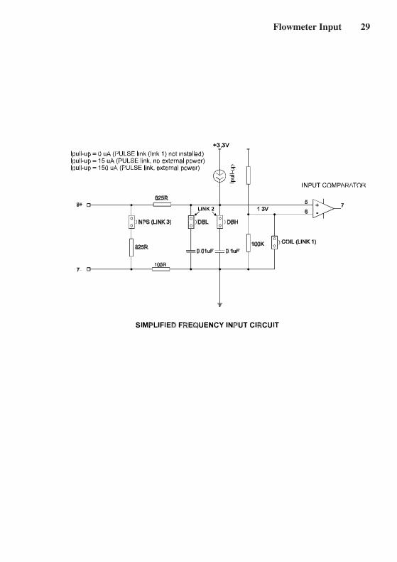
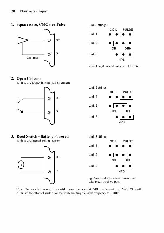
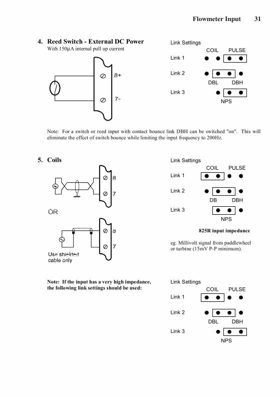
hour or day.Frequency Range: 0.01Hz to 10kHz.Signal Type: Link settable for sinewave (15mV P-P minimum),
open collector, reed switch, pulse or Namurproximity switch.
Battery Powered Version
Type: Two lithium battery packs.Battery Life: 5 years typical.
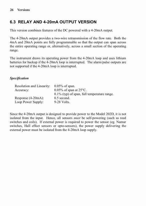
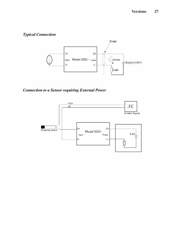
Loop Powered 4-20mA Output Version
Scale: The 4mA and 20mA points are programmable.Resolution and Linearity: 0.05% of span.Accuracy: 0.05% of span at 25°C.
0.1% (typ) of span, full temperature range.Update Time: 0.5 second.Connection: Two-wire.Loop Power Supply: 9-28 Volts.Supply Backup: Lithium battery.
Specification 7
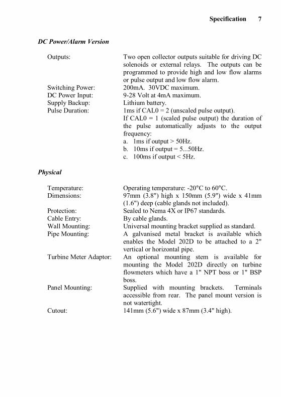
DC Power/Alarm Version
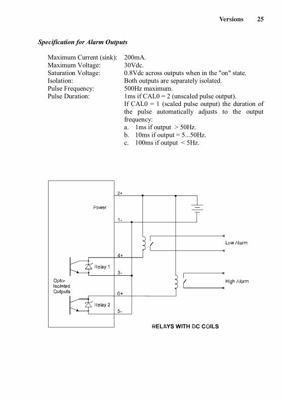
Outputs: Two open collector outputs suitable for driving DCsolenoids or external relays. The outputs can beprogrammed to provide high and low flow alarmsor pulse output and low flow alarm.
Switching Power: 200mA. 30VDC maximum.DC Power Input: 9-28 Volt at 4mA maximum.Supply Backup: Lithium battery.Pulse Duration: 1ms if CAL0 = 2 (unscaled pulse output).
If CAL0 = 1 (scaled pulse output) the duration ofthe pulse automatically adjusts to the outputfrequency:a. 1ms if output > 50Hz.b. 10ms if output = 5...50Hz.c. 100ms if output < 5Hz.
Physical
Temperature: Operating temperature: -20°C to 60°C.Dimensions: 97mm (3.8") high x 150mm (5.9") wide x 41mm
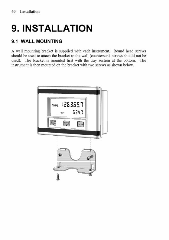
(1.6") deep (cable glands not included).Protection: Sealed to Nema 4X or IP67 standards.Cable Entry: By cable glands.Wall Mounting: Universal mounting bracket supplied as standard.Pipe Mounting: A galvanised metal bracket is available which
enables the Model 202D to be attached to a 2"vertical or horizontal pipe.
Turbine Meter Adaptor: An optional mounting stem is available formounting the Model 202D directly on turbineflowmeters which have a 1" NPT boss or 1" BSPboss.
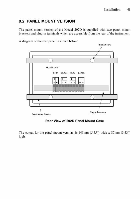
Panel Mounting: Supplied with mounting brackets. Terminalsaccessible from rear. The panel mount version isnot watertight.
Cutout: 141mm (5.6") wide x 87mm (3.4" high).
Operation8
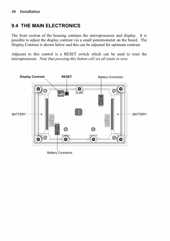
3. OPERATIONThe Model 202D Rate Totaliser accepts a frequency or pulse input from a widerange of flowmeters. The instrument is fully programmable with all operatingparameters and calculation constants programmable from the front panel. Thesetup parameters are stored in a non-volatile memory and are retained for at least40 years in the event of a power loss.
3.1 DISPLAY
The Model 202D displays:RateResettable TotalAccumulated Total
Both the Rate and Resettable Total are displayed continuously. The AccumulatedTotal is displayed only when the ACCUM TOTAL key is pressed.
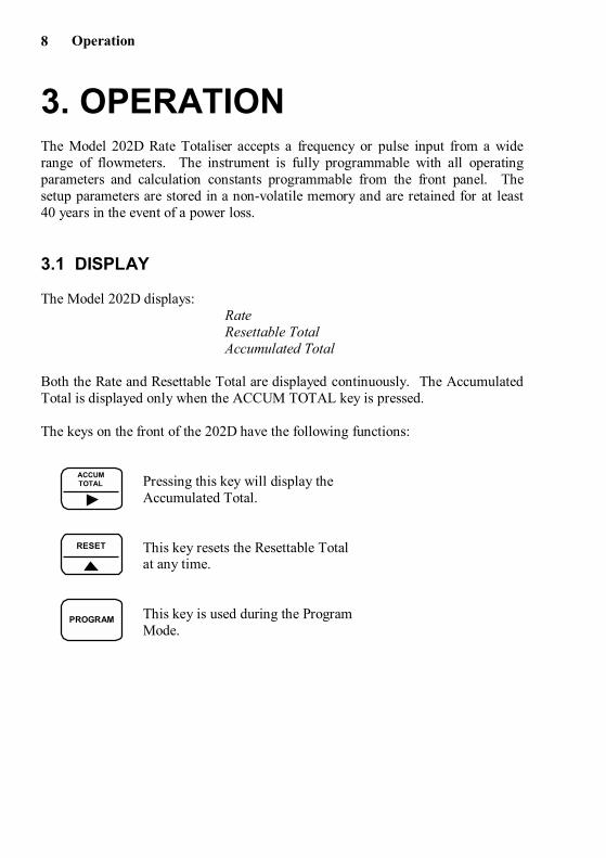
The keys on the front of the 202D have the following functions:
Pressing this key will display theAccumulated Total.
This key resets the Resettable Totalat any time.
This key is used during the ProgramMode.
RESET
PROGRAM
ACCUMTOTAL
Operation 9
3.2 TEST MODE
The 202D has a Test Mode which can be entered by simultaneously pressing all 3front panel keys. The tests are as follows:
Low Test By pressing the ACCUM TOTAL key, the lowalarm output (if installed) will go low. If a 4-20mA option is installed, the output will go to4mA.
High Test By pressing the RESET key, and depending on theprogrammed pulse output mode, the high alarmoutput (if installed):a. will go low if CAL0 = 0 (high alarm output).b. will output 100ms pulses every 0.5 sec if CAL0
= 1 (scaled pulse output).c. will output 1ms pulses every 0.5 sec if CAL0 =
2 (unscaled pulse output).If a 4-20mA option is installed, the output will goto 20mA.
Display Test By pressing the PROGRAM key, all segments ofthe display will flash.
To exit Test Mode, all three front panel keys are pressed simultaneously.
Operation10
3.3 FILTERING
Frequency fluctuations caused by pulsating flow through a flowmeter can interferewith the precision of the rate. For this reason, the Model 202D has a digital filterwhich will average out these fluctuations and enable accurate readings.
The degree of filtering of the input signal can be adjusted depending on the amountof fluctuation and the particular application. Values from 1 to 99 can beprogrammed where 1 corresponds to no filtering and 99 corresponds to heavyfiltering. Such flexibility in filtering means that highly accurate and stablereadings can be obtained.
When programming the degree of filtering, it is advisable to start with no filtering(the factor equals 1) and gradually increase until a steady reading is obtained. It isimportant that the filtering is not too heavy because this will cause an overdampedresponse.
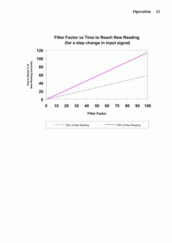
The following graph shows the time to reach 90% and 99% of a new reading for astep change in input signal.
Operation 11
Filter Factor vs Time to Reach New Reading (for a step change in input signal)
0
20
40
60
80
100
120
0 10 20 30 40 50 60 70 80 90 100
Filter Factor
Tim
e to
Rea
ch %
of
New
Rea
ding
(sec
onds
)
90% of New Reading 99% of New Reading
Operation12
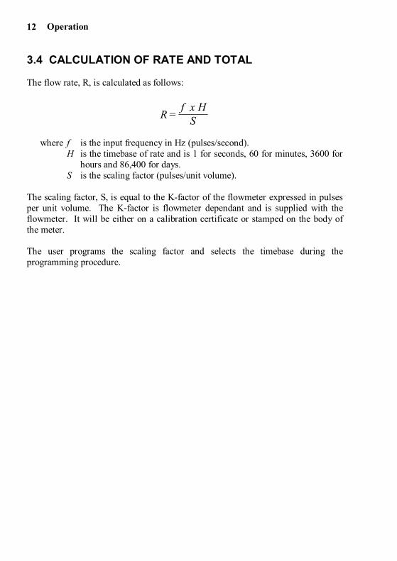
3.4 CALCULATION OF RATE AND TOTAL
The flow rate, R, is calculated as follows:
where f is the input frequency in Hz (pulses/second).H is the timebase of rate and is 1 for seconds, 60 for minutes, 3600 for
hours and 86,400 for days.S is the scaling factor (pulses/unit volume).
The scaling factor, S, is equal to the K-factor of the flowmeter expressed in pulsesper unit volume. The K-factor is flowmeter dependant and is supplied with theflowmeter. It will be either on a calibration certificate or stamped on the body ofthe meter.
The user programs the scaling factor and selects the timebase during theprogramming procedure.
Rf x H
S =
Operation 13
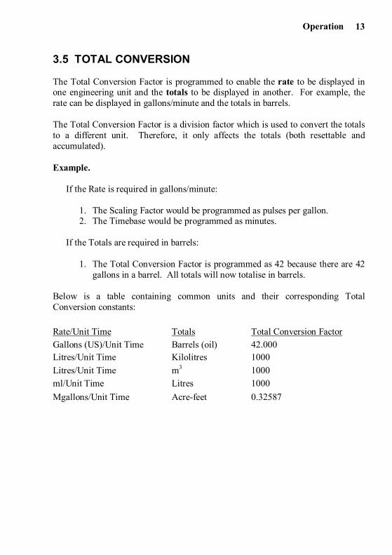
3.5 TOTAL CONVERSION
The Total Conversion Factor is programmed to enable the rate to be displayed inone engineering unit and the totals to be displayed in another. For example, therate can be displayed in gallons/minute and the totals in barrels.
The Total Conversion Factor is a division factor which is used to convert the totalsto a different unit. Therefore, it only affects the totals (both resettable andaccumulated).
Example.
If the Rate is required in gallons/minute:
1. The Scaling Factor would be programmed as pulses per gallon.2. The Timebase would be programmed as minutes.
If the Totals are required in barrels:
1. The Total Conversion Factor is programmed as 42 because there are 42gallons in a barrel. All totals will now totalise in barrels.
Below is a table containing common units and their corresponding TotalConversion constants:
Rate/Unit Time Totals Total Conversion FactorGallons (US)/Unit Time Barrels (oil) 42.000Litres/Unit Time Kilolitres 1000Litres/Unit Time m3 1000ml/Unit Time Litres 1000Mgallons/Unit Time Acre-feet 0.32587
Operation14
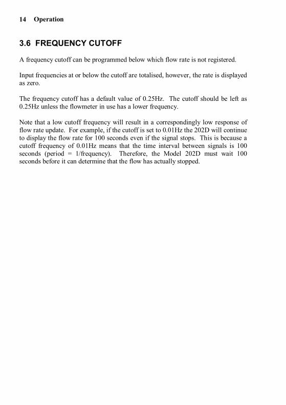
3.6 FREQUENCY CUTOFF
A frequency cutoff can be programmed below which flow rate is not registered.
Input frequencies at or below the cutoff are totalised, however, the rate is displayedas zero.
The frequency cutoff has a default value of 0.25Hz. The cutoff should be left as0.25Hz unless the flowmeter in use has a lower frequency.
Note that a low cutoff frequency will result in a correspondingly low response offlow rate update. For example, if the cutoff is set to 0.01Hz the 202D will continueto display the flow rate for 100 seconds even if the signal stops. This is because acutoff frequency of 0.01Hz means that the time interval between signals is 100seconds (period = 1/frequency). Therefore, the Model 202D must wait 100seconds before it can determine that the flow has actually stopped.
Programming 15
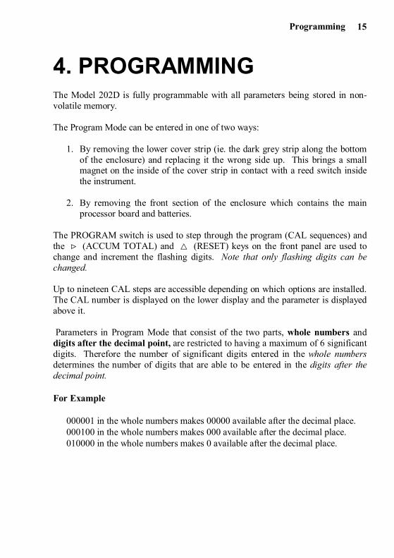
4. PROGRAMMINGThe Model 202D is fully programmable with all parameters being stored in non-volatile memory.
The Program Mode can be entered in one of two ways:
1. By removing the lower cover strip (ie. the dark grey strip along the bottomof the enclosure) and replacing it the wrong side up. This brings a smallmagnet on the inside of the cover strip in contact with a reed switch insidethe instrument.
2. By removing the front section of the enclosure which contains the mainprocessor board and batteries.
The PROGRAM switch is used to step through the program (CAL sequences) andthe û (ACCUM TOTAL) and < (RESET) keys on the front panel are used tochange and increment the flashing digits. Note that only flashing digits can bechanged.
Up to nineteen CAL steps are accessible depending on which options are installed.The CAL number is displayed on the lower display and the parameter is displayedabove it.
Parameters in Program Mode that consist of the two parts, whole numbers anddigits after the decimal point, are restricted to having a maximum of 6 significantdigits. Therefore the number of significant digits entered in the whole numbersdetermines the number of digits that are able to be entered in the digits after thedecimal point.
For Example
000001 in the whole numbers makes 00000 available after the decimal place.000100 in the whole numbers makes 000 available after the decimal place.010000 in the whole numbers makes 0 available after the decimal place.
Programming16
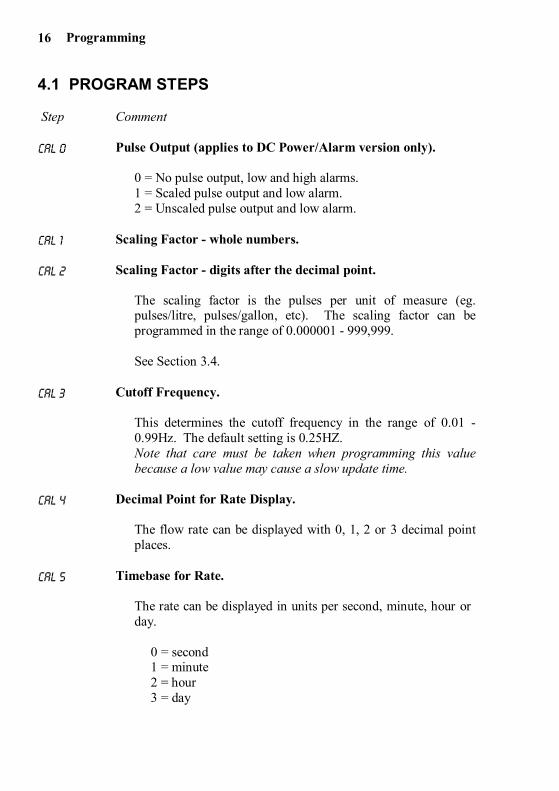
4.1 PROGRAM STEPS
Step Comment
CAL 0 Pulse Output (applies to DC Power/Alarm version only).
0 = No pulse output, low and high alarms.1 = Scaled pulse output and low alarm.2 = Unscaled pulse output and low alarm.
CAL 1 Scaling Factor - whole numbers.
CAL 2 Scaling Factor - digits after the decimal point.
The scaling factor is the pulses per unit of measure (eg.pulses/litre, pulses/gallon, etc). The scaling factor can beprogrammed in the range of 0.000001 - 999,999.
See Section 3.4.
CAL 3 Cutoff Frequency.
This determines the cutoff frequency in the range of 0.01 -0.99Hz. The default setting is 0.25HZ.Note that care must be taken when programming this valuebecause a low value may cause a slow update time.
CAL 4 Decimal Point for Rate Display.
The flow rate can be displayed with 0, 1, 2 or 3 decimal pointplaces.
CAL 5 Timebase for Rate.
The rate can be displayed in units per second, minute, hour orday.
0 = second1 = minute2 = hour3 = day
Programming 17
Step Comment
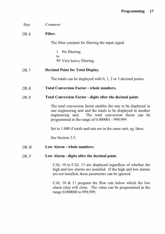
CAL 6 Filter.
The filter constant for filtering the input signal.
1 No filtering.to99 Very heavy filtering.
CAL 7 Decimal Point for Total Display.
The totals can be displayed with 0, 1, 2 or 3 decimal points.
CAL 8 Total Conversion Factor - whole numbers.
CAL 9 Total Conversion Factor - digits after the decimal point.
The total conversion factor enables the rate to be displayed inone engineering unit and the totals to be displayed in anotherengineering unit. The total conversion factor can beprogrammed in the range of 0.000001 - 999,999.
Set to 1.000 if totals and rate are in the same unit, eg. litres.
See Section 3.5.
CAL 10 Low Alarm - whole numbers.
CAL 11 Low Alarm - digits after the decimal point.
CAL 10 to CAL 13 are displayed regardless of whether thehigh and low alarms are installed. If the high and low alarmsare not installed, these parameters can be ignored.
CAL 10 & 11 program the flow rate below which the lowalarm relay will close. The value can be programmed in therange 0.000000 to 999,999.
Programming18
Step Comment
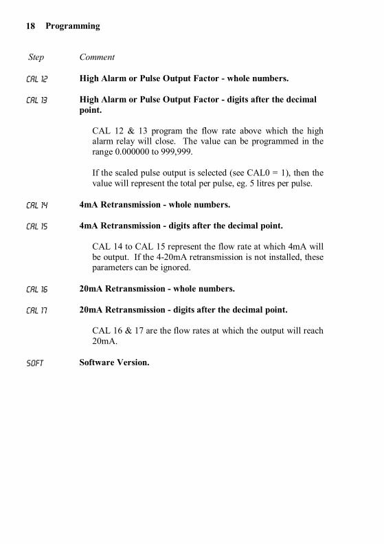
CAL 12 High Alarm or Pulse Output Factor - whole numbers.
CAL 13 High Alarm or Pulse Output Factor - digits after the decimalpoint.
CAL 12 & 13 program the flow rate above which the highalarm relay will close. The value can be programmed in therange 0.000000 to 999,999.
If the scaled pulse output is selected (see CAL0 = 1), then thevalue will represent the total per pulse, eg. 5 litres per pulse.
CAL 14 4mA Retransmission - whole numbers.
CAL 15 4mA Retransmission - digits after the decimal point.
CAL 14 to CAL 15 represent the flow rate at which 4mA willbe output. If the 4-20mA retransmission is not installed, theseparameters can be ignored.
CAL 16 20mA Retransmission - whole numbers.
CAL 17 20mA Retransmission - digits after the decimal point.
CAL 16 & 17 are the flow rates at which the output will reach20mA.
SOFT Software Version.
Programming 19
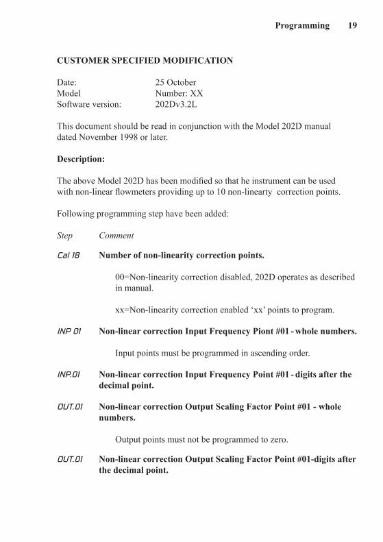
CUSTOMER SPECIFIED MODIFICATION
Date: 25 OctoberModel Number: XXSoftware version: 202Dv3.2L
This document should be read in conjunction with the Model 202D manual dated November 1998 or later.
Description:
The above Model 202D has been modified so that he instrument can be used with non-linear flowmeters providing up to 10 non-linearty correction points.
Following programming step have been added:
Step Comment
Cal 18 Number of non-linearity correction points. 00=Non-linearity correction disabled, 202D operates as described in manual. xx=Non-linearity correction enabled ‘xx’ points to program.
INP 01 Non-linear correction Input Frequency Piont #01 - whole numbers.
Input points must be programmed in ascending order.
INP.01 Non-linear correction Input Frequency Point #01 - digits after the decimal point.
OUT.01 Non-linear correction Output Scaling Factor Point #01 - whole numbers. Output points must not be programmed to zero.
OUT.01 Non-linear correction Output Scaling Factor Point #01-digits after the decimal point.
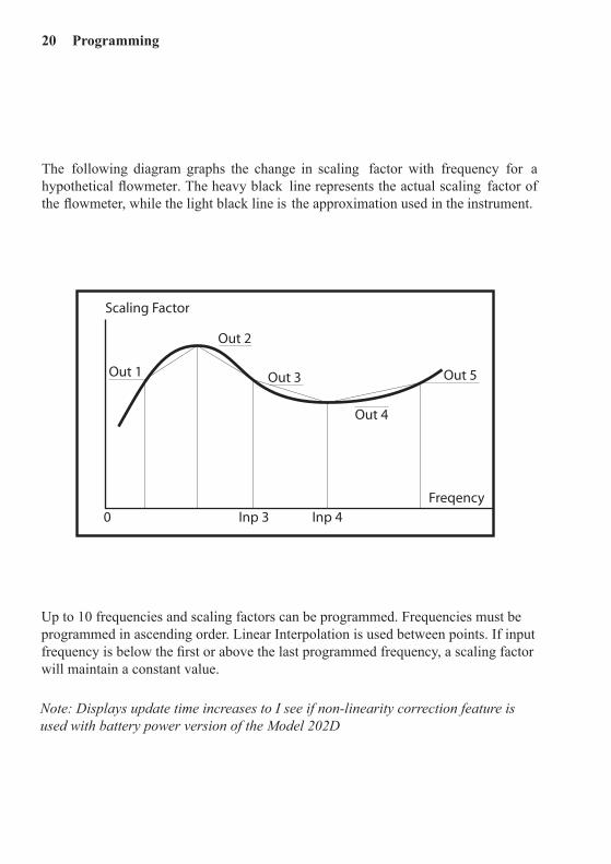
The following diagram graphs the change in scaling factor with frequency for a hypothetical flowmeter. The heavy black line represents the actual scaling factor of the flowmeter, while the light black line is the approximation used in the instrument.
Up to 10 frequencies and scaling factors can be programmed. Frequencies must be programmed in ascending order. Linear Interpolation is used between points. If input frequency is below the first or above the last programmed frequency, a scaling factor will maintain a constant value.
Out 2
Out 3Out 1
Out 4
Out 5
Inp 4Inp 3
Scaling Factor
Freqency0
Note:DisplaysupdatetimeincreasestoIseeifnon-linearitycorrectionfeatureisusedwithbatterypowerversionoftheModel202D
20 Programming


♦ ♦ ♦ ♦ ♦
µµ
µ
µ
µ