Embed Size (px)
Citation preview

1
Università degli Studi dell’Aquila
Ingegneria
Corso di Laurea Magistrale in
Ingegneria Meccanica
TESI di LAUREA
DELAMINATION IN GFRP FIBRE/RESIN INTERFACE
Relatore Studente
Prof. Antoniomaria Di Ilio Francesco Di Paolo
Adviser Matricola
209734
Dr. Safa Hashim
A.A. 2012 - 2013

2
DELAMINATION IN GFRP FIBRE/RESIN INTERFACE
Francesco Di Paolo
School of Engineering,
College of Science and Engineering,
University of Glasgow
June 2013

3
ACKNOWLEDGMENTS
This project would not have been possible without the support of many people.
Many thanks to my adviser, dr Safa Hashim, who surprised me for his great passion and
kindness, always ready to help me to solve my doubts and attentive to my ideas.
Thanks to Najeeb Yahya for the time he spent with me, guiding me during all the bonding
process of the specimens and the preparation of the tests.
Also thanks to John Davidson for the assistance he gave us during the tests at the
Structural Testing Lab in the Rankine Lab and for all his precious advices in order to find a
High Speed Camera.
Thanks to Patrick Harkness, who provided us the high speed camera and taught us how to
use it.
Also thanks to James Sharp, who was keen to solve some of my doubts about glass and
his properties.
And, at last, I want to thank my two friends, Zhongying and Carmelo, for having showed a
sincere interest in my project and for having helped me reasoning about what I was doing.

4
SUMMARY
1. Introduction
2. Literature Review
3. Research Summary
4. Production of specimens
1. Specimens
2. Bonding Process
3. High Speed Camera
5. Mechanical Testing
6. Finite Element Analysis
1. Influence of Tensile Stress on Transversal Strength
2. Influence of Fibre size
3. Influence of Voids
7. Results and Discussions
1. Comparing with previous research
8. Design Summary - Scale Model Design
1. Aim of the Scale Model
2. Dimensional analysis
3. Materials
4. Vertical Load
5. Horizontal Load
6. FE Model
9. Conclusions
10. References
Appendix A: GFRP, epoxy matrix (isotropic)
Appendix B: Photron Fastcam-SA3 High Speed Camera
5
1. INTRODUCTION
1.1 ABSTRACT
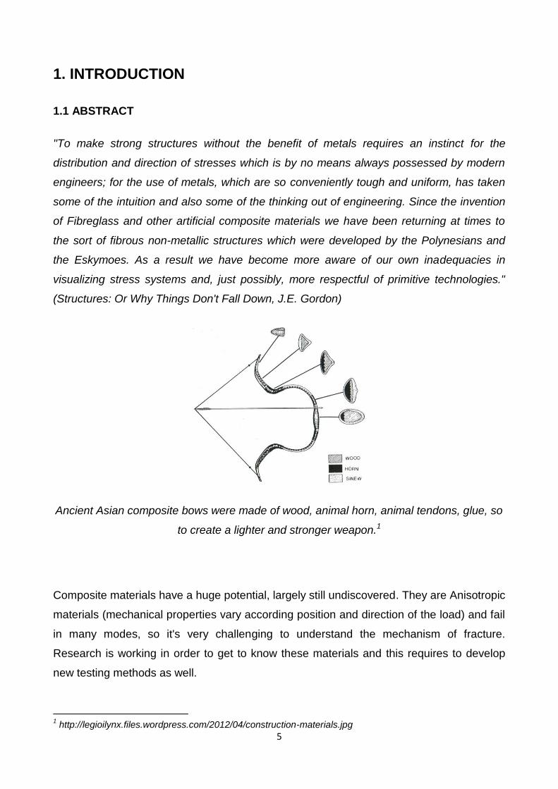
"To make strong structures without the benefit of metals requires an instinct for the
distribution and direction of stresses which is by no means always possessed by modern
engineers; for the use of metals, which are so conveniently tough and uniform, has taken
some of the intuition and also some of the thinking out of engineering. Since the invention
of Fibreglass and other artificial composite materials we have been returning at times to
the sort of fibrous non-metallic structures which were developed by the Polynesians and
the Eskymoes. As a result we have become more aware of our own inadequacies in
visualizing stress systems and, just possibly, more respectful of primitive technologies."
(Structures: Or Why Things Don't Fall Down, J.E. Gordon)
Ancient Asian composite bows were made of wood, animal horn, animal tendons, glue, so
to create a lighter and stronger weapon.1
Composite materials have a huge potential, largely still undiscovered. They are Anisotropic
materials (mechanical properties vary according position and direction of the load) and fail
in many modes, so it's very challenging to understand the mechanism of fracture.
Research is working in order to get to know these materials and this requires to develop
new testing methods as well.
1 http://legioilynx.files.wordpress.com/2012/04/construction-materials.jpg
6
This project tries to deepen the understanding of the distribution of stresses in Glass Fibre
Composite Plastics (GFRP), the influence of tensile stress on transverse strength of a
single fiber, the influence of micro voids within the composite and the behavior of a real
GFRP joint. In addition, the results have determined the need of designing a new type of
mechanical test.
1.2 GFRP 2
Fiberglass (or fibreglass) (also called glass-reinforced plastic, GRP, glass-fiber reinforced
plastic, or GFRP) is a fiber reinforced polymer made of a plastic matrix reinforced by fine
fibers of glass. It is also known as GFK (for German: Glasfaserverstärkter Kunststoff).
Fiberglass is a lightweight, extremely strong, and robust material. Although strength
properties are somewhat lower than carbon fiber and it is less stiff, the material is typically
far less brittle, and the raw materials are much less expensive. Its bulk strength and weight
properties are also very favorable when compared to metals, and it can be easily formed
using molding processes.
The plastic matrix may be epoxy, a thermosetting plastic (most often polyester or
vinylester) or thermoplastic.
Common uses of fiberglass include high performance aircraft (gliders), boats, automobiles,
baths, hot tubs, water tanks, roofing, pipes, cladding, casts, surfboards and external door
skins.
1.2.1 Fiber
Unlike glass fibers used for insulation, for the final structure to be strong, the fiber's
surfaces must be almost entirely free of defects, as this permits the fibers to reach Giga
Pascal tensile strengths. If a bulk piece of glass were to be defect free, then it would be
2 from Wikipedia: http://en.wikipedia.org/wiki/Fiberglass
7
equally as strong as glass fibers; however, it is generally impractical to produce bulk
material in a defect-free state outside of laboratory conditions.
1.2.2 Production
The manufacturing process for glass fibers suitable for reinforcement uses large furnaces
to gradually melt the silica sand, limestone, kaolin clay, fluorspar, colemanite, dolomite and
other minerals to liquid form. Then it is extruded through bushings, which are bundles of
very small orifices (typically 5–25 micrometres in diameter for E-Glass, 9 micrometres for
S-Glass). These filaments are then sized (coated) with a chemical solution. The individual
filaments are now bundled together in large numbers to provide a roving.
The diameter of the filaments, as well as the number of filaments in the roving determine
its weight. This is typically expressed in yield-yards per pound (how many yards of fiber in
one pound of material, thus a smaller number means a heavier roving, example of
standard yields are 225yield, 450yield, 675yield) or in tex-grams per km (how many grams
1 km of roving weighs, this is inverted from yield, thus a smaller number means a lighter
roving, examples of standard tex are 750tex, 1100tex, 2200tex).
These rovings are then either used directly in a composite application such as pultrusion,
filament winding (pipe), gun roving (automated gun chops the glass into short lengths and
drops it into a jet of resin, projected onto the surface of a mold), or used in an intermediary
step, to manufacture fabrics such as chopped strand mat (CSM) (made of randomly
oriented small cut lengths of fiber all bonded together), woven fabrics, knit fabrics or uni-
directional fabrics.
1.2.3 Sizing
A sort of coating, or primer, is used which both helps protect the glass filaments for
processing/manipulation as well as ensure proper bonding to the resin matrix, thus
allowing for transfer of shear loads from the glass fibers to the thermoset plastic. Without
this bonding, the fibers can 'slip' in the matrix and localized failure would ensue.
8
1.2.4 Properties
An individual structural glass fiber is both stiff and strong in tension and compression—that
is, along its axis. Although it might be assumed that the fiber is weak in compression, it is
actually only the long aspect ratio of the fiber which makes it seem so; i.e., because a
typical fiber is long and narrow, it buckles easily. On the other hand, the glass fiber is weak
in shear—that is, across its axis. Therefore if a collection of fibers can be arranged
permanently in a preferred direction within a material, and if the fibers can be prevented
from buckling in compression, then that material will become preferentially strong in that
direction.
Furthermore, by laying multiple layers of fiber on top of one another, with each layer
oriented in various preferred directions, the stiffness and strength properties of the overall
material can be controlled in an efficient manner. In the case of fiberglass, it is the plastic
matrix which permanently constrains the structural glass fibers to directions chosen by the
designer. With chopped strand mat, this directionality is essentially an entire two
dimensional plane; with woven fabrics or unidirectional layers, directionality of stiffness
and strength can be more precisely controlled within the plane.
A fiberglass component is typically of a thin "shell" construction, sometimes filled on the
inside with structural foam, as in the case of surfboards. The component may be of nearly
arbitrary shape, limited only by the complexity and tolerances of the mold used for
manufacturing the shell.
1.2.5 Applications
Fiberglass is an immensely versatile material which combines its light weight with an
inherent strength to provide a weather resistant finish, with a variety of surface textures.
The development of fiber reinforced plastic for commercial use was being extensively
researched in the 1930s. It was particularly of interest to the aviation industry. Mass
production of glass strands was accidentally discovered in 1932 when a researcher at the
Owens-Illinois directed a jet of compressed air at a stream of molten glass and produced
9
fibers. Owens joined up with the Corning company in 1935 and the method was adapted
by Owens Corning to produce its patented "Fiberglas" (one "s").
A suitable resin for combining the "Fiberglas" with a plastic was developed in 1936 by du
Pont. The first ancestor of modern polyester resins is Cyanamid's of 1942. Peroxide curing
systems were used by then. During World War II it was developed as a replacement for
the molded plywood used in aircraft radomes (fiberglass being transparent to microwaves).
Its first main civilian application was for building of boats and sports car bodies, where it
gained acceptance in the 1950s.
Its use has broadened to the automotive and sport equipment sectors as well as aircraft,
although its use there is now partly being taken over by carbon fiber which weighs less per
given volume and is stronger both by volume and by weight. Fiberglass uses also include
hot tubs, pipes for drinking water and sewers, office plant display containers and flat roof
systems.
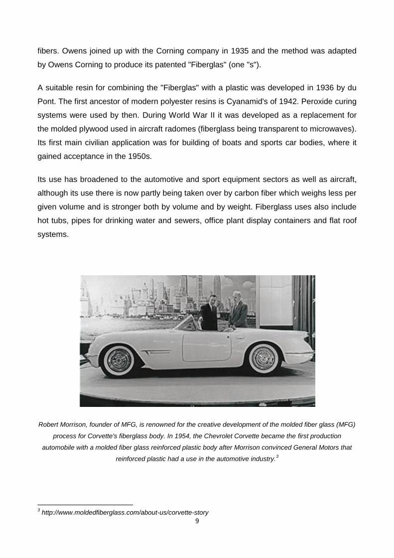
Robert Morrison, founder of MFG, is renowned for the creative development of the molded fiber glass (MFG)
process for Corvette's fiberglass body. In 1954, the Chevrolet Corvette became the first production
automobile with a molded fiber glass reinforced plastic body after Morrison convinced General Motors that
reinforced plastic had a use in the automotive industry.3
3 http://www.moldedfiberglass.com/about-us/corvette-story

10
Fiberglass is also used in the telecommunications industry for shrouding the visual
appearance of antennas, due to its RF permeability and low signal attenuation properties.
It may also be used to shroud the visual appearance of other equipment where no signal
permeability is required, such as equipment cabinets and steel support structures, due to
the ease with which it can be molded, manufactured and painted to custom designs, to
blend in with existing structures or brickwork. Other uses include sheet form made
electrical insulators and other structural components commonly found in the power
industries.
Because of fiberglass's light weight and durability, it is often used in protective equipment,
such as helmets. Many sports utilize fiberglass protective gear, such as modern
goaltender masks and newer baseball catcher's masks.
Storage Tanks. Storage tanks can be made of fiberglass with capacities up to
about 300 tonnes. The smaller tanks can be made with chopped strand mat cast
over a thermoplastic inner tank which acts as a preform during construction. Much
more reliable tanks are made using woven mat or filament wound fibre with the fibre
orientation at right angles to the hoop stress imposed in the side wall by the
contents. They tend to be used for chemical storage because the plastic liner (often
polypropylene) is resistant to a wide range of strong chemicals. Fiberglass tanks
are also used for septic tanks.
House Building. Glass reinforced plastics are also used in the house building
market for the production of roofing laminate, door surrounds, over-door canopies,
window canopies and dormers, chimneys, coping systems, heads with keystones
and sills. The use of fiberglass for these applications provides for a much faster
installation and due to the reduced weight manual handling issues are reduced.
With the advent of high volume manufacturing processes it is possible to construct
fiberglass brick effect panels which can be used in the construction of composite
housing. These panels can be constructed with the appropriate insulation which
reduces heat loss.
Piping. GRP and GRE pipe systems can be used for a variety of applications,
above and under the ground.
Firewater systems
Cooling water systems
11
Drinking water systems
Waste water systems/Sewage systems
Gas systems
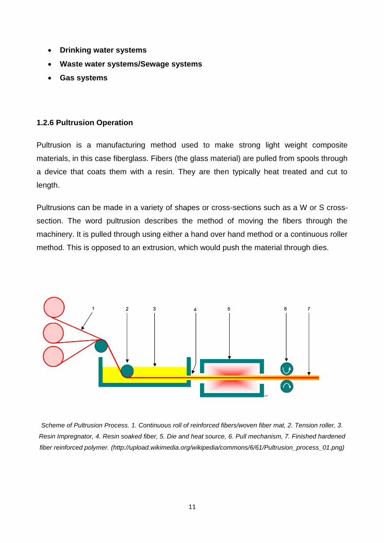
1.2.6 Pultrusion Operation
Pultrusion is a manufacturing method used to make strong light weight composite
materials, in this case fiberglass. Fibers (the glass material) are pulled from spools through
a device that coats them with a resin. They are then typically heat treated and cut to
length.
Pultrusions can be made in a variety of shapes or cross-sections such as a W or S cross-
section. The word pultrusion describes the method of moving the fibers through the
machinery. It is pulled through using either a hand over hand method or a continuous roller
method. This is opposed to an extrusion, which would push the material through dies.
Scheme of Pultrusion Process. 1. Continuous roll of reinforced fibers/woven fiber mat, 2. Tension roller, 3.
Resin Impregnator, 4. Resin soaked fiber, 5. Die and heat source, 6. Pull mechanism, 7. Finished hardened
fiber reinforced polymer. (http://upload.wikimedia.org/wikipedia/commons/6/61/Pultrusion_process_01.png)
12
1.2.7 Warping and Voids
One notable feature of fiberglass is that the resins used are subject to contraction during
the curing process. For polyester this contraction is often of the order of 5-6%, and for
epoxy it can be much lower, about 2%.
When formed as part of fiberglass, because the fibers don't contract, the differential can
create changes in the shape of the part during cure. Distortions will usually appear hours,
days or weeks after the resin has set.
While this can be minimized by symmetric use of the fibers in the design, nevertheless
internal stresses are created, and if these become too great, then cracks will form.
1.2.8 Examples of fiberglass use
Surfboards, tent poles
Gliders, kit cars, sports cars, microcars, karts, bodyshells, boats, kayaks, flat roofs,
lorries, K21 Infantry Fighting Vehicle.
Minesweeper hulls
Pods, domes and architectural features where a light weight is necessary.
High end bicycles.
Bodyparts for an entire automobiles, such as the Anadol, Reliant, Quantum
Quantum Coupé, Chevrolet Corvette and Studebaker Avanti, and DeLorean DMC-
12 under body.
Sub sea installation protection covers
Re-enforcement of asphalt pavement, as a fabric or mesh interlayer between lifts
Protective helmets used in various sports.
Orthopedic casts.
Fiberglass Grating is used for walkways on ships, oil rigs and in factories.

13
The DeLorean DMC-12 has gull-wing doors with a fiberglass "underbody", to which non-structural brushed
stainless steel panels are affixed 4
A320 radome.
FRP tanks and vessels: FRP is used extensively to manufacture chemical
equipment and tanks and vessels. BS4994 is a British standard related to this
application.
UHF-broadcasting antennas are often mounted inside a fiberglass cylinder on the
pinnacle of a broadcasting tower
Most commercial velomobiles
Most printed circuit boards used in electronics consist of alternating layers of copper
and fibreglass FR-4.
Large Commercial wind turbine Blades
RF coils used in MRI scanners
4 © 1990 Universal City Studios, INC.
14
1.2.9 Carbon vs. Fiberglass5
The vast majority of fibers used in composites are carbon fiber and fiberglass. The choice
of whether to use carbon or fiberglass in your application depends on many factors. Below
is a breakdown of the most important carbon and fiberglass characteristics.
1. Carbon fiber composites:
a. Lightweight: 70% lighter than steel, 40% lighter than Aluminum
b. High stiffness-to-weight ratio: Also known as specific stiffness, this ratio
allows materials of different mass to be compared quickly in rigidity-sensitive
applications where weight is still a factor. Carbon fiber is about 3 times stiffer
than steel and aluminum for a given weight.
c. Low thermal expansion: As opposed to most other materials, carbon fiber
has a negative coefficient of thermal expansion. This means that it expands
when the temperature lowers. The matrix will have a positive coefficient,
resulting in a near neutral for the composite. This is a desirable quality for
applications that have to operate in a wide range of temperatures.
d. High fatigue level: Carbon fiber composites keep their mechanical properties
under dynamic loads, rather than deteriorating slowly over time.
e. Corrosion resistant: Carbon and fiberglass composites alike perform well in
an acidic or otherwise chemically challenging environment. Additives in the
resin can enhance this property.
2. Fiberglass composites :
a. High strength-to-weight ratio: Also known as specific strength, this number
allows you to compare materials of different mass for applications where
resistance against breaking has priority. Being more flexible, it means that
glassfiber typically has a higher ultimate breaking point than a similarly
shaped carbon fiber product.
b. Cost effective: Fiberglass composites are less expensive than carbon
composites in most cases
c. Non-conductive: Fiberglass composites are insulators, which means they do
not respond to an electric field and resist the flow of electric charge.
5 http://gwcomposites.com/carbon-vs-fiberglass/
15
d. Corrosion resistant: Carbon and fiberglass composites alike perform well in
an acidic or otherwise chemically challenging environment. Additives in the
resin can enhance this property.
e. No radio-signal interference (Radiolucent): Glassfiber composites are very
radiolucent, which means they allow radiation to pass through it freely. This
makes glassfiber rods very capable antennas.
There appears to be no agreement whether carbon or glass fiber is the material of choice
for Naval vessels. At least one country’s Navy has chosen to use carbon fibers for their
advanced surface combatants, whereas numerous other Navies have selected to use
glass fiber for their structures. Presumably all designers base their choices of materials on
cost and performance, but their conclusions differ. The most economical choice depends
on the cost of material, production cost, life cycle cost, and material properties. Weight
savings and performance, naturally, play a major factor in the choice of materials. For
aerospace structures, it is clear that carbon fiber is superior to glass fiber from a
performance/cost standpoint since superfluous weight is very costly. In the case of ships,
the requirements are quite different and the structures are not as sensitive to excess
weight. The manufacturing of ships cannot, due to cost, be as meticulous. It also does not
need to be because the damage tolerance requirements are so high.6
1.3 ADHESIVE 7
An adhesive is any substance that, when applied to the surfaces of materials, binds the
surfaces together and resists separation. The term "adhesive" may be used
interchangeably with glue, cement, mucilage, or paste. Adjectives may be used in
conjunction with the word “adhesive” to describe properties based on the substance's
physical form, its chemical form, the type of materials it is used to join, or the conditions
under which it is applied.
6 "Comparison of mechanical properties of glass fiber/vinyl ester and carbon fiber/vinyl ester composites", Composites:
Part B 36 (2005) 417–426 7 from Wikipedia: http://en.wikipedia.org/wiki/Adhesive

16
The use of adhesives offers many advantages over other binding techniques such as
sewing, welding, bolting, screwing, etc. These advantages include the ability to bind
different materials together, the ability to distribute stress more efficiently across the joint,
the cost effectiveness of an easily mechanized process, an improvement in aesthetic
design, and an increased design flexibility.
Disadvantages of adhesive use include decreased stability at high temperatures, relative
weakness in bonding large objects with a small bonding surface area, and greater difficulty
in separating objects during testing.
Schematic showing bonded areas on a modern aircraft (Courtesy Boeing Company)
Adhesives may be found naturally or be produced synthetically. The earliest use of
adhesive-like substances by humans was approximately 200,000 years ago. From then
until the 1900s, increases in adhesive use and discovery were relatively gradual. Only
since the last century has the development of synthetic adhesives accelerated rapidly, and
innovation in the field continues to the present.

17
The 1920s, 1930s, and 1940s witnessed great advances in the development and
production of new plastics and resins due to the World Wars. These advances greatly
improved the development of adhesives by allowing the use of newly developed materials
that exhibited a variety of properties. With changing needs and ever evolving technology,
the development of new synthetic adhesives continues to the present. However, due to
their low cost, natural adhesives are still more commonly used.
1.3.1 Mechanisms of adhesion
Adhesion, the attachment between adhesive and substrate may occur either by
mechanical means, in which the adhesive works its way into small pores of the substrate,
or by one of several chemical mechanisms. The strength of adhesion depends on many
factors, including the means by which it occurs.
8
In some cases, an actual chemical bond occurs between adhesive and substrate. In
others, electrostatic forces, as in static electricity, hold the substances together. A third
8 from the notes of Materials and Manufacture M3, Dr Safa Hashim, University of Glasgow
18
mechanism involves the van der Waals forces that develop between molecules. A fourth
means involves the moisture-aided diffusion of the glue into the substrate, followed by
hardening.
1.3.2 Failure of Adhesive Joints
There are several factors that could contribute to the failure of two adhered surfaces.
Sunlight and heat may weaken the adhesive. Solvents can deteriorate or dissolve
adhesive. Physical stresses may also cause the separation of surfaces. When subjected to
loading, debonding may occur at different locations in the adhesive joint. The major
fracture types are the following:
A. Cohesive fracture. Cohesive fracture is obtained if a crack propagates in the bulk
polymer which constitutes the adhesive. In this case the surfaces of both adherents
after debonding will be covered by fractured adhesive. The crack may propagate in
the center of the layer or near an interface. For this last case, the cohesive fracture
can be said to be “cohesive near the interface”.
B. Interfacial fracture. The fracture is adhesive or interfacial when debonding occurs
between the adhesive and the adherent. In most cases, the occurrence of interfacial
fracture for a given adhesive goes along with a smaller fracture toughness. The
interfacial character of a fracture surface is usually to identify the precise location of
the crack path in the interface.
C. Mixed fracture, which occurs if the crack propagates at some spots in a cohesive
and in others in an interfacial manner. Mixed fracture surfaces can be characterized
by a certain percentage of adhesive and cohesive areas.
D. The alternating crack path type which occurs if the cracks jump from one interface
to the other. This type of fracture appears in the presence of tensile pre-stresses in
the adhesive layer.
Fracture can also occur in the adherent if the adhesive is tougher than the adherent. In this
case, the adhesive remains intact and is still bonded to one substrate and remnants of the
other. For example, when one removes a price label, the adhesive usually remains on the
label and the surface. This is cohesive failure. If, however, a layer of paper remains stuck
to the surface, the adhesive has not failed. Another example is when someone tries to pull
19
apart Oreo cookies and all the filling remains on one side; this is an adhesive failure, rather
than a cohesive failure.
1.3.3 Design of Adhesive Joints
As a general design rule, the material properties of the object need to be greater than the
forces anticipated during its use. (i.e. geometry, loads, etc.). The engineering work will
consist of having a good model to evaluate the function. For most adhesive joints, this can
be achieved using fracture mechanics.
Concepts such as the stress concentration factor and the strain energy release rate can be
used to predict failure. In such models, the behavior of the adhesive layer itself is
neglected and only the adherents are considered.
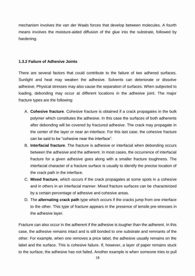
Failure will also very much depend on the opening mode of the joint.
http://upload.wikimedia.org/wikipedia/commons/e/e7/Fracture_modes_v2.svg
Mode I is an opening or tensile mode where the loadings are normal to the crack.
Mode II is a sliding or in-plane shear mode where the crack surfaces slide over one
another in direction perpendicular to the leading edge of the crack. This is typically
the mode for which the adhesive exhibits the highest resistance to fracture.
Mode III is a tearing or antiplane shear mode.

20
As the loads are usually fixed, an acceptable design will result from combination of a
material selection procedure and geometry modifications, if possible. In adhesively bonded
structures, the global geometry and loads are fixed by structural considerations and the
design procedure focuses on the material properties of the adhesive and on local changes
on the geometry.
9
Increasing the joint resistance is usually obtained by designing its geometry so that:
The bonded zone is large
It is mainly loaded in mode II
Stable crack propagation will follow the appearance of a local failure.
9 from the notes of Materials and Manufacture M3, Dr Safa Hashim, University of Glasgow
21
2. LITERATURE REVIEW
Studies carried on GFRP have showed the huge potential of this material and, above all,
the topics that need to be investigated in order make this technology predominant in a lot
of applications. The following statements are an extract from:
An investigation into failure and behaviour of GFRP pultrusion joints, S.A. Hashim
n, J.A. Nisar (School of Engineering, University of Glasgow, Glasgow G12 8QQ,
UK)10
Meso-scale laminate adhesive joints for pultrusions, J.A. Nisar, S.A. Hashim
(School of Engineering, University of Glasgow, Glasgow G12 8QQ, UK)11
Researchers have found that:
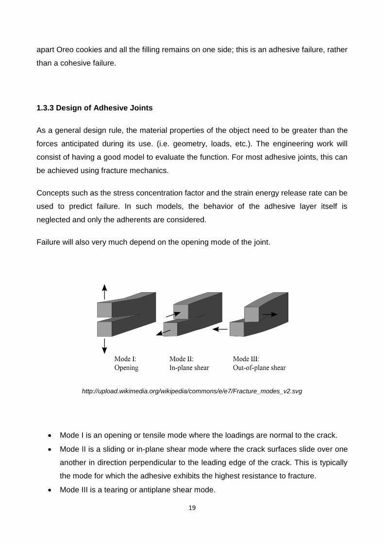
The potential of glass fibre reinforced plastic (GFRP), using vinyl ester resin for
pultrusions in marine and similar structures, can be realized if the structural
efficiency of the adhesive joint for these sections is increased.
Pultrusion is one of the few continuous processes for composite manufacture,
which could potentially make it one of the cheapest, for weight-critical structures,
e.g. ship decks and superstructures.
Efficient methods of joining composite structures are either adhesively bonding
or mechanically fastening. The tensile strength capacity of mechanical fastened
joints is 50% of the adherend tensile strength. The low capacity is largely due to
local stress concentration caused by fasteners. The introduction of holes in the
composite leads to high stress concentrations and hence thicker and heavier walls.
An adhesively bonded joint could be more efficient if attention is paid to the detail of
the joint and composite at surface and subsurface levels. However, the tensile
strength capacity of adhesively bonded joint has the potential to reach 80% of the
adherend tensile strength. This is very significant considering the high longitudinal
tensile strength of some pultruded sections. However, it is currently unreasonable to
expect better than 40% structural efficiency for a basic DLS (double lap shear)
joints based on commercial GFRP pultrusion. This has been improved to over 50%
by introducing a low viscosity resin coating to the bonding surface prior to bonding
10
International Journal of Adhesion & Adhesives 40 (2013) 80–88 11
International Journal of Adhesion & Adhesives 30 (2010) 763–773
22
plus using metallic outer adherends. The low-viscosity resin provides good micro-
flow on the surface, resulting in a better wettability between the adhesive and the
adherend.
Previous research on lap-shear joints for pultrusions with random outer mats, has
shown that failure initiates in the adhesive spew fillet or in the outer mat layers of
the pultruded laminate at the joint edge. Cracks then easily propagate between the
mat layers (usually random mat) where there is little through thickness
reinforcement and an inherent stress concentration.
However, a pultrusion made entirely from glass UD fabric layers has no surface
ply as such, so the delamination mechanism detailed above does not take place.
The failure occurs a few filaments deep into the composite and hence the strength
of this type of material could be superior to the more traditional ‘‘sandwich’’ lay-up
with surface mats. Failure occurs when the surface layer delaminates from the
adherend in the overlap region through a combination of through thickness tensile
(transverse) and shear stresses in the composite. Failure may also be initiated at
the interlaminar between fabric and roving interface into the overlap region of
composite—the former is believed to be the most critical.
Herakovich and Mirzadeh examined the fibre spacing and resin-rich areas in
pultruded composites and concluded that significant strength reduction is due to
uneven fibre distribution and spacing between them.
Pultruded composite shows a non-linear response during loading, which is due
to the nature of different materials’ lay-up but the major impact is due to the voids
and micro-defects.
Wang and Zureick studied the tensile behavior of pultruded I-section beam
structure. Void content is relatively high in pultruded composites as compared to the
composites made up by other methods. They also showed large numbers of voids
at different locations of an I-beam, which affect its strength in both longitudinal and
transverse directions. Void content in the pultruded profile to be about 3–5%.
One of the limitations of the pultrusion process is resin heat transfer problem
due to high exothermic curing reactions and low thermal conductivity. Therefore the
variation in temperature during the process generates voids and cracks on the
pultruded parts quoted by Paciornik et al. They pointed out that these defects and
cracks are due to improper resin heat transfer during curing that affect the
mechanical properties as well as help moisture absorption.
23
However, vinyl ester resin as a matrix with glass fibre performed well to control
the heat transfer problem and variation in temperature during pultrusion process.
Ganga Rao and Palakamshetty have published work on the factors that should be
considered when designing for pultruded adhesive bonded joints, e.g.
o joint efficiency/stiffness,
o stress concentration,
o failure mode,
o design guide for strong and optimized structural support.
Liu and Hillier research relating to the pultrusion process considers fibre with the
control of the critical process parameter, such as
o die temperature and distribution,
o pull speed,
o content and
o resin kinematic.
Hartley highlights the general rules of thumb in a pultrusion overview. In addition,
Hartley has also pointed out that although vast amounts of research have been
done in the pultrusion process it is still described as a ‘trial and error’ type
process. Therefore, voids are part of the make-up of pultruded sections, and in fact
voids and micro-defects in pultruded industrial composites were found to be similar
to a lab-made coupon.
Different failure criteria are active in the literature over the years, but there are still
considerable conflicts about which criteria are the best. The problem of carrying out
reasonable tests and the lack of good experimental data has made it difficult to
resolve this issue.
Pre-coating the pultrusion with epoxy resin has resulted in a considerable
increase in joint strength.
A cheaper solution is using vinyl ester matrix resin. The transverse strength of
such a composite is lower than the equivalent with epoxy matrix.
it was mostly agreed that failure criteria often takes place due to transverse shear
and transverse tensile stresses. However, Nisar et al. and Lees et al. are more
inclined to suggest that the transverse tensile component is the main cause of
failure in bonded composite. The same view is shared by da Silva et al.who explain
that this is due to the low through thickness stiffness and low transverse tensile
strength.
24
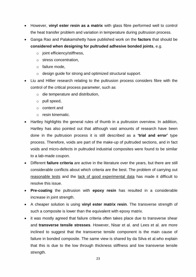
The failure associated with these transverse stresses (both shear and tensile) may
be referred to as interlaminar or interlaminar failure. The latter is perhaps a more
appropriate term, especially where failure takes place within a roving reinforcement
or ply rather than in the resin separating these layers.
(from: An investigation into failure and behaviour of GFRP pultrusion joints, S.A. Hashim n, J.A. Nisar
(School of Engineering, University of Glasgow, Glasgow G12 8QQ, UK))12
Previous work on UD pultrusions indicated that failure ultimately takes place at
filament/matrix level. Although the single fibre pull-out shear strength model is
widely used to characterize fibre–matrix interfaces, the transverse strength at the
filament–matrix interface has also been a subject of study in recent years. These
stresses, however, may be produced by in-plane buckling or out of plane bending.
Therefore the failure mechanisms generated in these specimens are significantly
different from the traction peel and shear stresses within composite adhesive joints.
Hence a different micro-model (and specimen) is needed to study the composite
failure within adhesive joints, typically in relation to DLS joints.
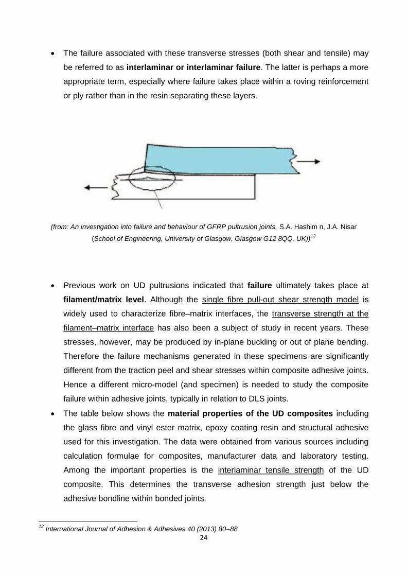
The table below shows the material properties of the UD composites including
the glass fibre and vinyl ester matrix, epoxy coating resin and structural adhesive
used for this investigation. The data were obtained from various sources including
calculation formulae for composites, manufacturer data and laboratory testing.
Among the important properties is the interlaminar tensile strength of the UD
composite. This determines the transverse adhesion strength just below the
adhesive bondline within bonded joints.
12
International Journal of Adhesion & Adhesives 40 (2013) 80–88
25
The authors also state that transverse tensile failure is more difficult to predict than
shear failure in a composite. Results suggest that the DLS joint has a structural
efficiency of about 57% which is the percentage joint failure load to that of the
adherend.
(from: An investigation into failure and behaviour of GFRP pultrusion joints, S.A. Hashim n, J.A. Nisar
(School of Engineering, University of Glasgow, Glasgow G12 8QQ, UK))13
Failure usually is intralaminar. It is extremely difficult to determine the exact
locus of failure because this often happens in a brittle and sudden manner. Fig. 3
shows the fractured surfaces of the meso- and macro-scale joints, probably largely
due to transverse tensile stresses. The failure may be regarded as being in
between as light fibre-tear failure to fibre-tear failure, in accordance with the ASTM
specification of bonded joints —another term for intralaminar failure. The optical
examinations of joint the failure surfaces of the specimens may be summarized as
follows.
Herakovich stated that stresses near the free edge are difficult to determine and
could be the cause of a premature failure.
13
International Journal of Adhesion & Adhesives 40 (2013) 80–88

26
A closer optical examination of the meso/shear specimen is shown in Fig. 4.
Highlighted areas include voids, resin rich areas, and uneven fibre spacing
(from: An investigation into failure and behaviour of GFRP pultrusion joints, S.A. Hashim n, J.A. Nisar
(School of Engineering, University of Glasgow, Glasgow G12 8QQ, UK))14
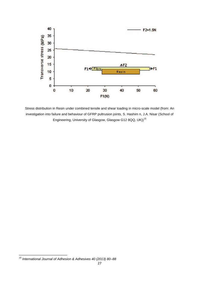
interaction of the transverse and longitudinal stresses. Ideally, this should be
represented by the corresponding S11 and S22 stresses but again, the model aims
to explain the behaviour rather than have corresponding stress values. Although
this represents a qualitative explanation, it clearly indicates that the level of
transverse stress within the composite can be suppressed by longitudinal
stresses/forces.
14
International Journal of Adhesion & Adhesives 40 (2013) 80–88
27
Stress distribution in Resin under combined tensile and shear loading in micro-scale model (from: An
investigation into failure and behaviour of GFRP pultrusion joints, S. Hashim n, J.A. Nisar (School of
Engineering, University of Glasgow, Glasgow G12 8QQ, UK))15
15
International Journal of Adhesion & Adhesives 40 (2013) 80–88
28
3. RESEARCH SUMMARY
Starting from previous researches, the aim of this study is to deepen the knowledge of
GFRP joints, in particular to better understand the relationship between Transverse stress
and Tensile stress and so the influence on the interlaminar failure. To accomplish this, it is
necessary to realize a Long Double Lap Shear Joint and test it in the laboratory but the
problem is that the failure is brittle and so it's difficult to understand what is the starting
point of the crack and how it propagates through the GFRP. This is why it has been
decided to use a High Speed Camera to record the test and show the mechanism of the
failure. The research can be resumed in this way:
1) Preparation of the Double Lap Shear Joint: specimens (inner adherend: GFRP;
outer adherend: steel), bonding process, set up of the High Speed Camera;
2) Mechanical Testing;
3) Finite Element Analysis: the software Abaqus allows to model the interface
between resin and fibre, in order to understand the influence of tensile stress, voids
size and fiber diameter on the Transverse strength;
4) Comparison with Literature and conclusions.
29
4. PRODUCTION OF SPECIMENS
4.1 SPECIMENS
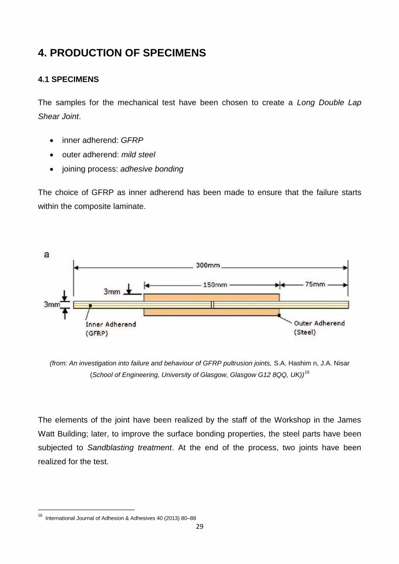
The samples for the mechanical test have been chosen to create a Long Double Lap
Shear Joint.
inner adherend: GFRP
outer adherend: mild steel
joining process: adhesive bonding
The choice of GFRP as inner adherend has been made to ensure that the failure starts
within the composite laminate.
(from: An investigation into failure and behaviour of GFRP pultrusion joints, S.A. Hashim n, J.A. Nisar
(School of Engineering, University of Glasgow, Glasgow G12 8QQ, UK))16
The elements of the joint have been realized by the staff of the Workshop in the James
Watt Building; later, to improve the surface bonding properties, the steel parts have been
subjected to Sandblasting treatment. At the end of the process, two joints have been
realized for the test.
16
International Journal of Adhesion & Adhesives 40 (2013) 80–88
30
Usually, the composite adherends are coated with a Low viscosity Epoxy resin to enhance
adhesion prior to bonding. It has been decided to do not use it in order to be sure that the
failure starts within the GFRP element.
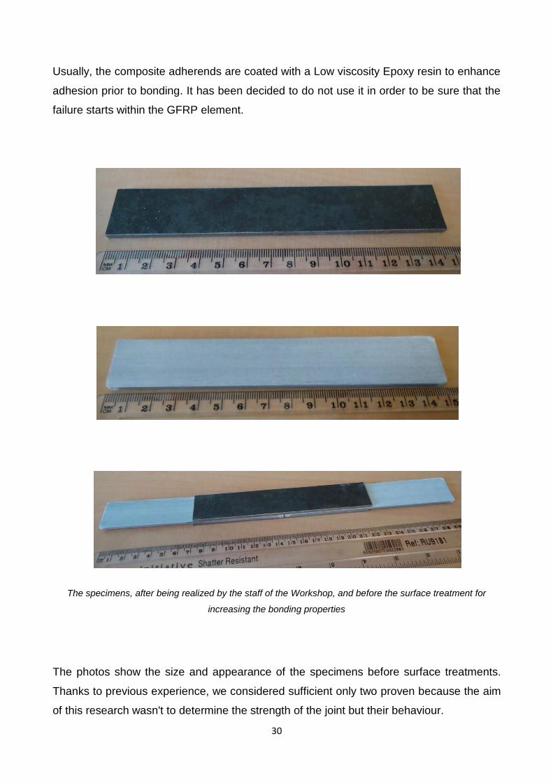
The specimens, after being realized by the staff of the Workshop, and before the surface treatment for
increasing the bonding properties
The photos show the size and appearance of the specimens before surface treatments.
Thanks to previous experience, we considered sufficient only two proven because the aim
of this research wasn't to determine the strength of the joint but their behaviour.
31
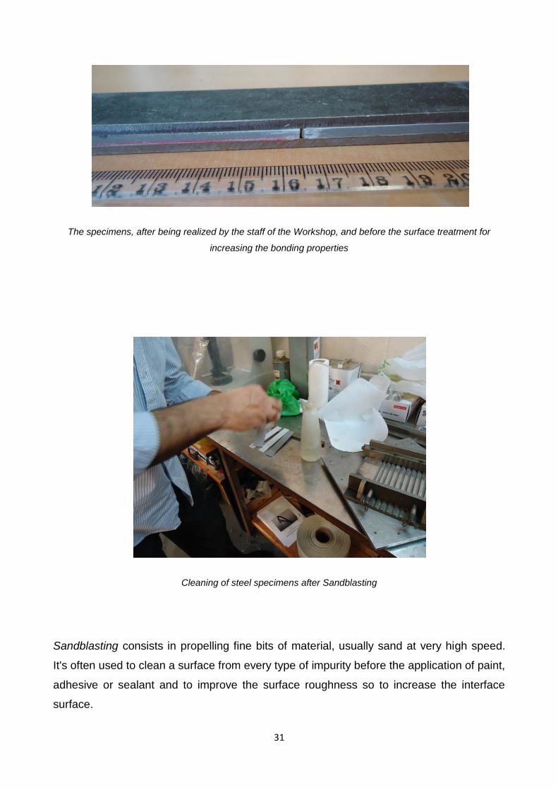
The specimens, after being realized by the staff of the Workshop, and before the surface treatment for
increasing the bonding properties
Cleaning of steel specimens after Sandblasting
Sandblasting consists in propelling fine bits of material, usually sand at very high speed.
It's often used to clean a surface from every type of impurity before the application of paint,
adhesive or sealant and to improve the surface roughness so to increase the interface
surface.

32
Cleaning of steel specimens after Sandblasting
Steel specimens before (left) and after (right) Sandblasting

33
4.2 BONDING PROCESS
To bond both laminates, it is necessary to use an adhesive. Epoxy adhesive Araldite 2015
(Huntsman) is very good for this kind of application. It required to be cured at 80 °C for 60
minutes, then slowly cooled inside the switched off oven, with the door open. It's sag-
resistant, tough epoxy adhesive with good shear strength, ideal for metals, sheet molding
compounds and fiberglass reinforced parts.
Epoxy adhesive Araldite 2015 (Huntsman)
34
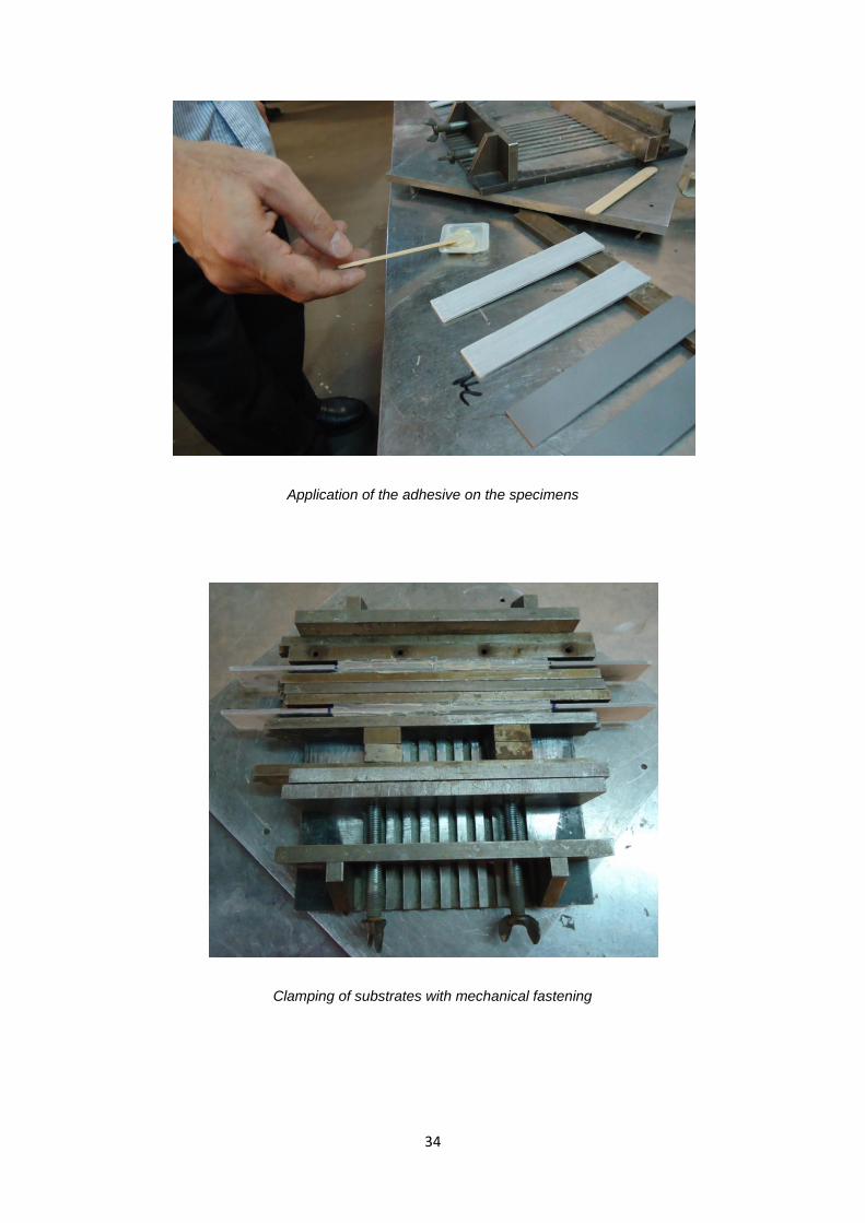
Application of the adhesive on the specimens
Clamping of substrates with mechanical fastening
35
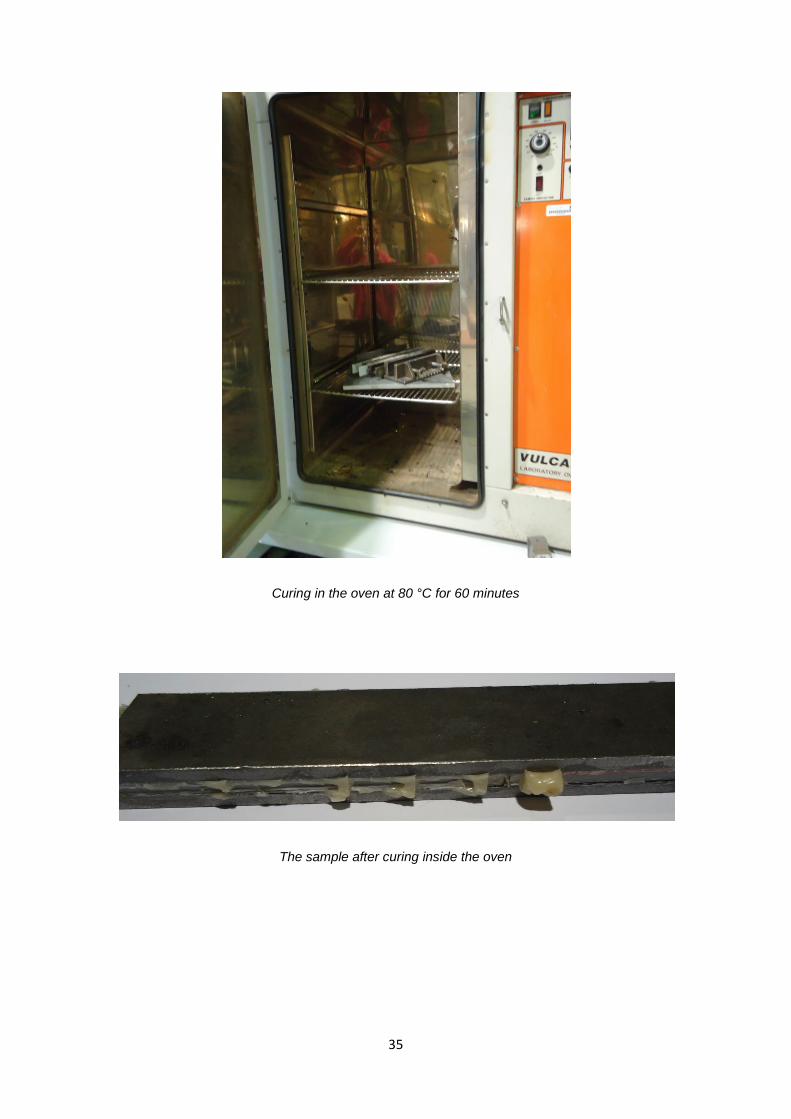
Curing in the oven at 80 °C for 60 minutes
The sample after curing inside the oven
36
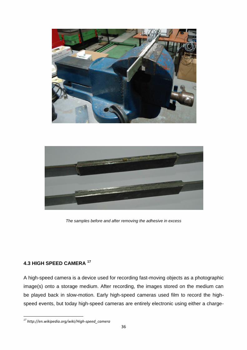
The samples before and after removing the adhesive in excess
4.3 HIGH SPEED CAMERA 17
A high-speed camera is a device used for recording fast-moving objects as a photographic
image(s) onto a storage medium. After recording, the images stored on the medium can
be played back in slow-motion. Early high-speed cameras used film to record the high-
speed events, but today high-speed cameras are entirely electronic using either a charge-
17
http://en.wikipedia.org/wiki/High-speed_camera
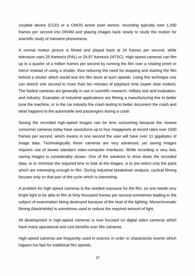
37
coupled device (CCD) or a CMOS active pixel sensor, recording typically over 1,000
frames per second into DRAM and playing images back slowly to study the motion for
scientific study of transient phenomena.
A normal motion picture is filmed and played back at 24 frames per second, while
television uses 25 frames/s (PAL) or 29.97 frames/s (NTSC). High-speed cameras can film
up to a quarter of a million frames per second by running the film over a rotating prism or
mirror instead of using a shutter, thus reducing the need for stopping and starting the film
behind a shutter which would tear the film stock at such speeds. Using this technique one
can stretch one second to more than ten minutes of playback time (super slow motion).
The fastest cameras are generally in use in scientific research, military test and evaluation,
and industry. Examples of industrial applications are filming a manufacturing line to better
tune the machine, or in the car industry the crash testing to better document the crash and
what happens to the automobile and passengers during a crash.
Saving the recorded high-speed images can be time consuming because the newest
consumer cameras today have resolutions up to four megapixels at record rates over 1000
frames per second, which means in one second the user will have over 11 gigabytes of
image data. Technologically these cameras are very advanced, yet saving images
requires use of slower standard video-computer interfaces. While recording is very fast,
saving images is considerably slower. One of the solutions to drive down the recorded
data, or to minimize the required time to look at the images, is to pre-select only the parts
which are interesting enough to film. During industrial breakdown analysis, cyclical filming
focuses only on that part of the cycle which is interesting.
A problem for high-speed cameras is the needed exposure for the film, so one needs very
bright light to be able to film at forty thousand frames per second sometimes leading to the
subject of examination being destroyed because of the heat of the lighting. Monochromatic
filming (black/white) is sometimes used to reduce the required amount of light.
All development in high-speed cameras is now focused on digital video cameras which
have many operational and cost benefits over film cameras.
High-speed cameras are frequently used in science in order to characterize events which
happen too fast for traditional film speeds.
38
The move from film to digital technology has greatly reduced the difficulty in use of these
technologies with unpredictable behaviors, specifically via the use of continuous recording
and post-triggering. With film high-speed cameras, an investigator must start the film then
attempt to entice the animal to perform the behavior in the short time before the film runs
out, resulting in many useless sequences where the animal behaves too late or not at all.
In modern digital high-speed cameras, the camera can simply record continuously as the
investigator attempts to elicit the behavior, following which a trigger button will stop the
recording and allow the investigator to save a given time interval prior, after or both, to the
trigger (determined by frame rate, image size and memory capacity during continuous
recording). Most software allows saving only a subset of recorded frames, minimizing file
size issues by eliminating useless frames before or after the sequence of interest.
Parameters you should consider:
Frame Rate
Image Resolution
Exposure Time (Shutter speed)
Sensitivity
Bit depth (dynamic range)
Colour or Monochrome
Camera interface
Physical size
Application issues you need to address 18
Sufficient time resolution: being able to see the event happen
Motion blur: being able to freeze the event
Light levels: having the right illumination source and camera sensitivity
Location: portability, communication cable lengths
Lens type: image coverage of sensor
Budget: Compromise but at what cost?
18
"How to choose a High Speed Camera", Photron's publication

39
The EPSRC Engineering Instrument Pool freely offered us on loan one of the two Photron
Fastcam SA-3 monochrome systems that they own.
Photron Fastcam SA-3 monochrome system
Photron Fastcam SA-3 monochrome system
40
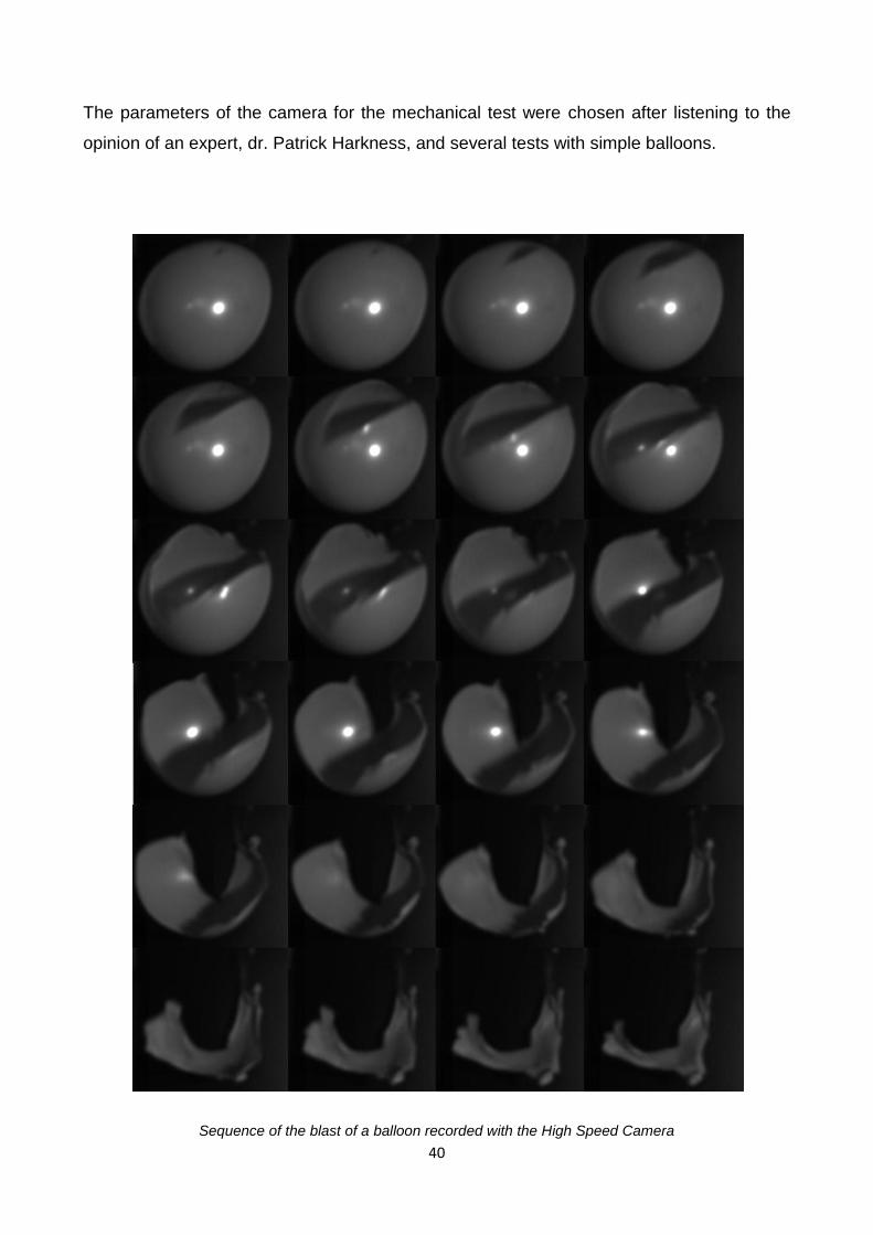
The parameters of the camera for the mechanical test were chosen after listening to the
opinion of an expert, dr. Patrick Harkness, and several tests with simple balloons.
Sequence of the blast of a balloon recorded with the High Speed Camera

41
This allowed to find the right parameters for the test:
frame rate: 8000 fps
time for recording: 1.02 seconds
resolution: 128 X 672
trigger mode: end (it records only the 1.02 seconds time interval before the trigger)
42
5. MECHANICAL TESTING
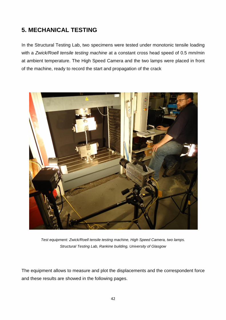
In the Structural Testing Lab, two specimens were tested under monotonic tensile loading
with a Zwick/Roell tensile testing machine at a constant cross head speed of 0.5 mm/min
at ambient temperature. The High Speed Camera and the two lamps were placed in front
of the machine, ready to record the start and propagation of the crack
Test equipment: Zwick/Roell tensile testing machine, High Speed Camera, two lamps.
Structural Testing Lab, Rankine building, University of Glasgow
The equipment allows to measure and plot the displacements and the correspondent force
and these results are showed in the following pages.
43
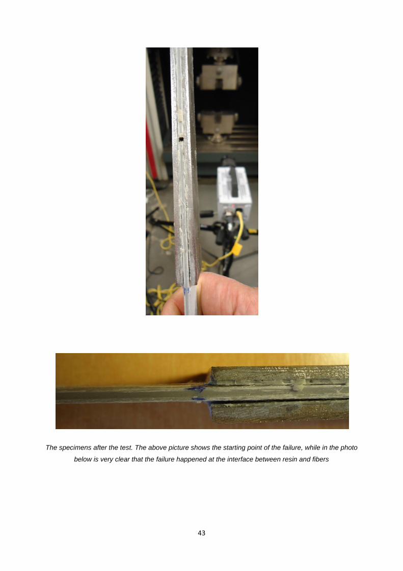
The specimens after the test. The above picture shows the starting point of the failure, while in the photo
below is very clear that the failure happened at the interface between resin and fibers
44
-2000
0
2000
4000
6000
8000
10000
12000
14000
-1 0 1 2 3
Forc
e [
N]
Displacement [mm]
Test 1
0
2000
4000
6000
8000
10000
12000
14000
16000
18000
-0.5 0 0.5 1 1.5 2 2.5 3
Forc
e [
N]
Displacement [mm]
Test 2
45
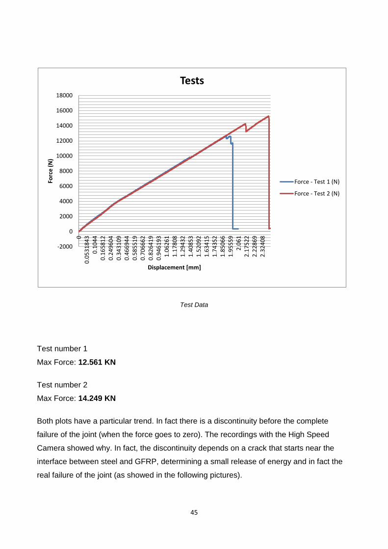
Test Data
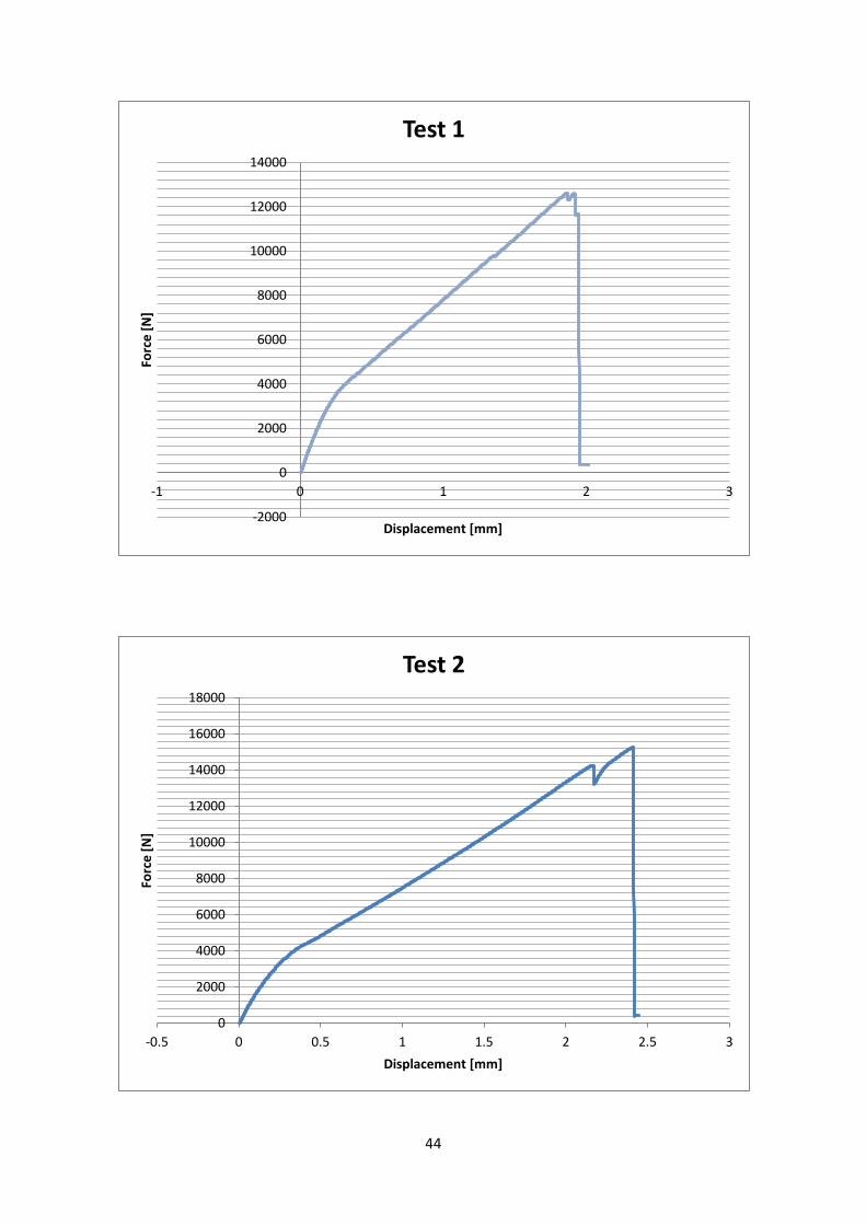
Test number 1
Max Force: 12.561 KN
Test number 2
Max Force: 14.249 KN
Both plots have a particular trend. In fact there is a discontinuity before the complete
failure of the joint (when the force goes to zero). The recordings with the High Speed
Camera showed why. In fact, the discontinuity depends on a crack that starts near the
interface between steel and GFRP, determining a small release of energy and in fact the
real failure of the joint (as showed in the following pictures).
-2000
0
2000
4000
6000
8000
10000
12000
14000
16000
18000
0
0.0
53
18
43
0
.10
44
0
.16
58
12
0
.24
96
04
0
.34
31
09
0
.46
69
44
0
.58
55
19
0
.70
66
62
0
.82
64
19
0
.94
61
93
1
.06
26
1
1.1
78
08
1
.29
43
2
1.4
08
53
1
.52
09
2
1.6
34
15
1
.74
35
2
1.8
50
66
1
.95
55
9
2.0
61
2
.17
52
2
2.2
28
69
2
.32
40
8
Forc
e (
N)
Displacement [mm]
Tests
Force - Test 1 (N)
Force - Test 2 (N)
46
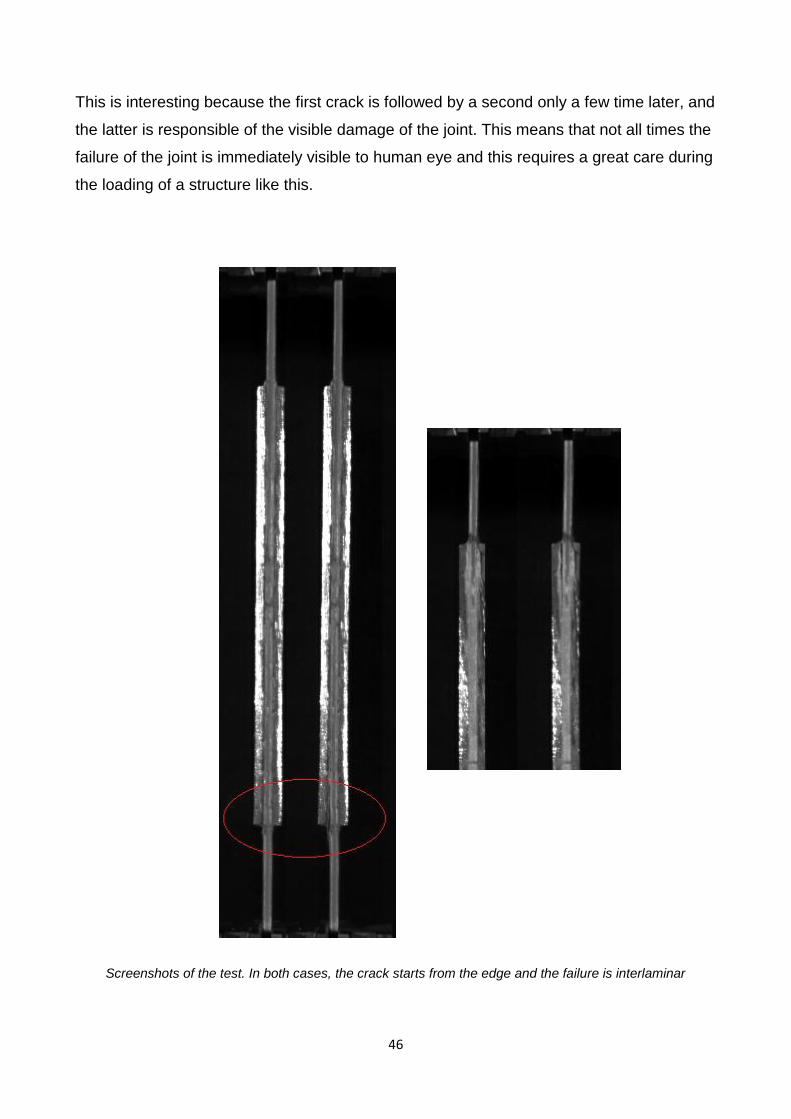
This is interesting because the first crack is followed by a second only a few time later, and
the latter is responsible of the visible damage of the joint. This means that not all times the
failure of the joint is immediately visible to human eye and this requires a great care during
the loading of a structure like this.
Screenshots of the test. In both cases, the crack starts from the edge and the failure is interlaminar
47
6. FINITE ELEMENT ANALYSIS
6.1 COMPUTER MODELING
The mechanical tests showed that the most critical point is where the tensile and
transverse stress are maximum. This event was not so likely because previous researches
showed that the tensile stress has a positive effect on transverse strength. The problem is
that without knowing in a quantitative way how much this influence is strong or not, it was
difficult to foresee the mechanism of the failure. So it's very interesting to try to model the
interface between the single glass fiber and the surrounding resin. This type of study has
been carried in past utilizing the Abaqus software, a Finite Element Analysis tool that
permits to study the distribution of stresses within the specimens. In previous researches,
it has been used only a 2-D model. The aim of this part of the project is to create a 3-D
model in order to study:
influence of Tensile Stress on Transverse Strength
influence of Fibre size
influence of Voids
6.2 INFLUENCE OF TENSILE STRESS ON TRANSVERSAL STRENGTH
The aim is modeling a small portion of a single fiber of glass bonded to resin, applying a
transverse stress in the center and in the meanwhile a tensile stress, so to understand the
relationship between these two.
fibre diameter: 15 μm
length: 1 mm
transverse stress: 10 MPa
tensile stress: 0, 10, 50, 200 MPa
Boundary conditions:
low resin surface: roller
48
end of the fiber: free
opposite end of the fiber: encastré
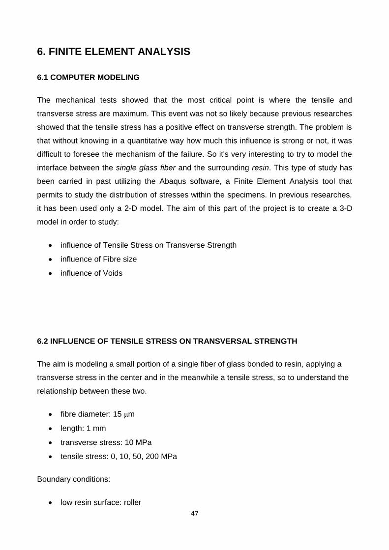
interface between fiber and resin: tie constraint
Undeformed model, with geometry, boundary conditions
Undeformed model, with applied loads
49
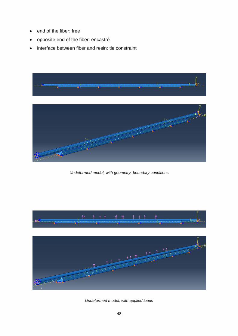
The picture clearly shows the tensile stress (on the left) and the transverse stress applied
in the middle part of the fiber. The resin element has an encastré on the lower surface (not
visible in the picture).
Tensile stress: 0 MPa; Transverse Stress: 10 MPa
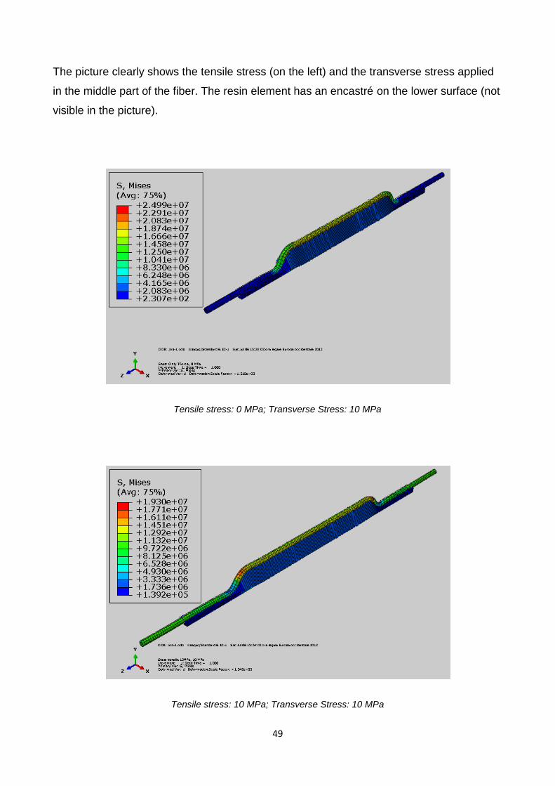
Tensile stress: 10 MPa; Transverse Stress: 10 MPa
50
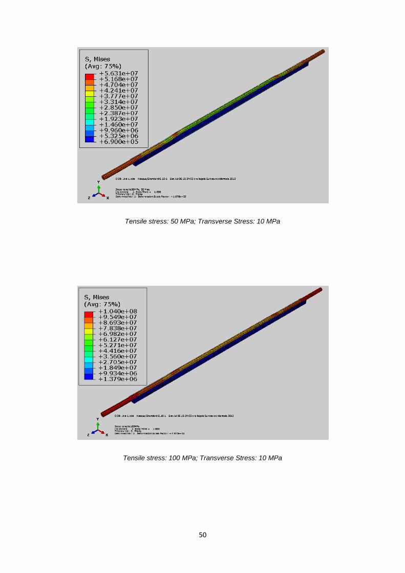
Tensile stress: 50 MPa; Transverse Stress: 10 MPa
Tensile stress: 100 MPa; Transverse Stress: 10 MPa
51
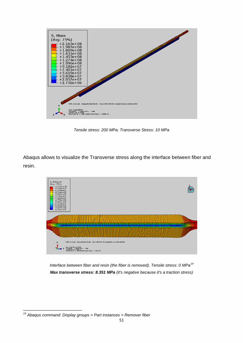
Tensile stress: 200 MPa; Transverse Stress: 10 MPa
Abaqus allows to visualize the Transverse stress along the interface between fiber and
resin.
Interface between fiber and resin (the fiber is removed). Tensile stress: 0 MPa19
Max transverse stress: 8.351 MPa (it's negative because it's a traction stress)
19
Abaqus command: Display groups > Part instances > Remover fiber
52
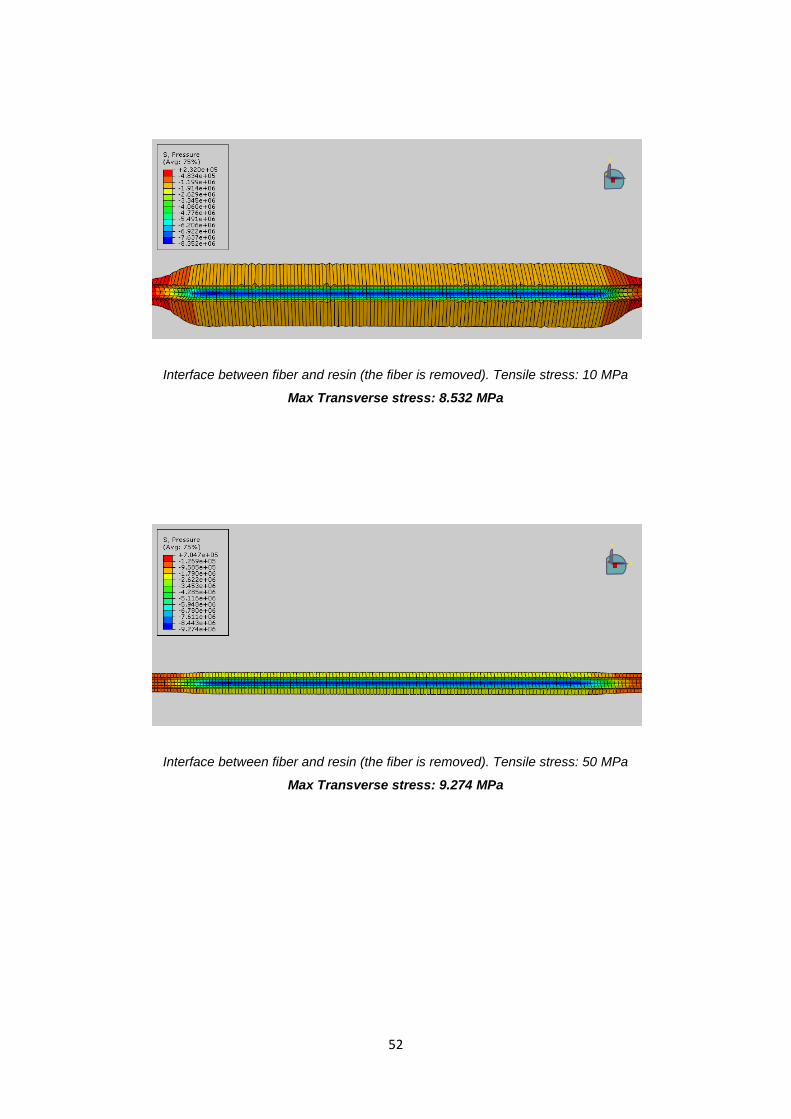
Interface between fiber and resin (the fiber is removed). Tensile stress: 10 MPa
Max Transverse stress: 8.532 MPa
Interface between fiber and resin (the fiber is removed). Tensile stress: 50 MPa
Max Transverse stress: 9.274 MPa

53
Interface between fiber and resin (the fiber is removed). Tensile stress: 100 MPa
Max Transverse stress: 10.2 MPa
Interface between fiber and resin (the fiber is removed). Tensile stress: 200 MPa
Max Transverse stress: 12.04 MPa
54
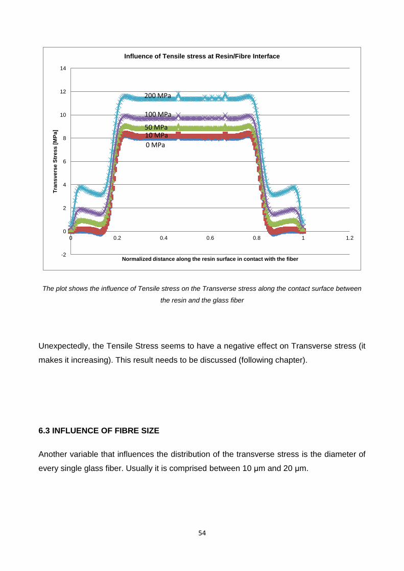
The plot shows the influence of Tensile stress on the Transverse stress along the contact surface between
the resin and the glass fiber
Unexpectedly, the Tensile Stress seems to have a negative effect on Transverse stress (it
makes it increasing). This result needs to be discussed (following chapter).
6.3 INFLUENCE OF FIBRE SIZE
Another variable that influences the distribution of the transverse stress is the diameter of
every single glass fiber. Usually it is comprised between 10 μm and 20 μm.
-2
0
2
4
6
8
10
12
14
0 0.2 0.4 0.6 0.8 1 1.2
Tra
ns
vers
e S
tress [
MP
a]
Normalized distance along the resin surface in contact with the fiber
Influence of Tensile stress at Resin/Fibre Interface
200 MPa
100 MPa
50 MPa 10 MPa
0 MPa
55
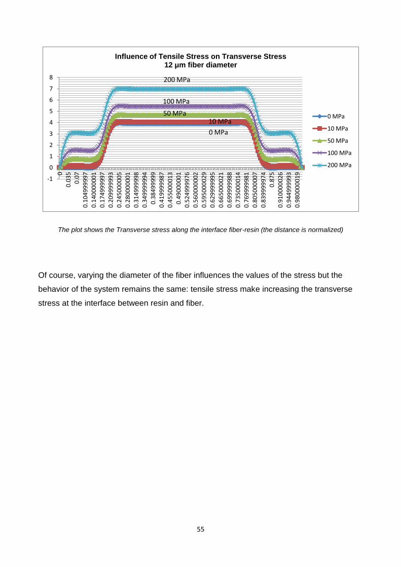
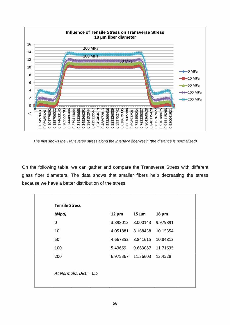
The plot shows the Transverse stress along the interface fiber-resin (the distance is normalized)
Of course, varying the diameter of the fiber influences the values of the stress but the
behavior of the system remains the same: tensile stress make increasing the transverse
stress at the interface between resin and fiber.
-1
0
1
2
3
4
5
6
7
8
0
0.0
35
0.0
7
0.1
04
99
99
97
0.1
40
00
00
01
0.1
74
99
99
97
0.2
09
99
99
93
0.2
45
00
00
05
0.2
80
00
00
01
0.3
14
99
99
98
0.3
49
99
99
94
0.3
84
99
99
9
0.4
19
99
99
87
0.4
55
00
00
13
0.4
90
00
00
1
0.5
24
99
99
76
0.5
60
00
00
02
0.5
95
00
00
29
0.6
29
99
99
95
0.6
65
00
00
21
0.6
99
99
99
88
0.7
35
00
00
14
0.7
69
99
99
81
0.8
05
00
00
07
0.8
39
99
99
74
0.8
75
0.9
10
00
00
26
0.9
44
99
99
93
0.9
80
00
00
19
Influence of Tensile Stress on Transverse Stress 12 μm fiber diameter
0 MPa
10 MPa
50 MPa
100 MPa
200 MPa
200 MPa
100 MPa
50 MPa 10 MPa
0 MPa
56
The plot shows the Transverse stress along the interface fiber-resin (the distance is normalized)
On the following table, we can gather and compare the Transverse Stress with different
glass fiber diameters. The data shows that smaller fibers help decreasing the stress
because we have a better distribution of the stress.
Tensile Stress
(Mpa) 12 μm 15 μm 18 μm
0
3.898013 8.000143 9.979891
10
4.051881 8.168438 10.15354
50
4.667352 8.841615 10.84812
100
5.43669 9.683087 11.71635
200
6.975367 11.36603 13.4528
At Normaliz. Dist. = 0.5
-2
0
2
4
6
8
10
12
14
16
0
0.0
34
92
66
31
0.0
69
85
32
61
0.1
04
77
98
92
0.1
39
70
65
22
0.1
74
63
31
45
0.2
09
55
97
83
0.2
44
48
64
06
0.2
79
41
30
44
0.3
14
33
96
68
0.3
49
26
62
91
0.3
84
19
29
44
0.4
19
11
95
67
0.4
54
04
61
9
0.4
88
97
28
13
0.5
23
89
94
36
0.5
58
82
60
89
0.5
93
75
27
42
0.6
28
67
93
35
0.6
63
60
59
88
0.6
98
53
25
81
0.7
33
45
92
34
0.7
68
38
58
87
0.8
04
36
06
28
0.8
40
33
54
29
0.8
75
26
20
22
0.9
10
18
86
75
0.9
45
11
52
68
0.9
80
04
19
21
Influence of Tensile Stress on Transverse Stress 18 μm fiber diameter
0 MPa
10 MPa
50 MPa
100 MPa
200 MPa
200 MPa
100 MPa 50 MPa
57
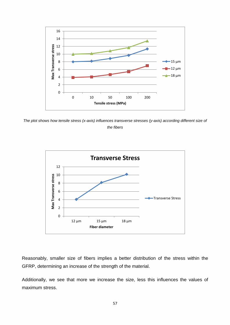
The plot shows how tensile stress (x-axis) influences transverse stresses (y-axis) according different size of
the fibers
Reasonably, smaller size of fibers implies a better distribution of the stress within the
GFRP, determining an increase of the strength of the material.
Additionally, we see that more we increase the size, less this influences the values of
maximum stress.
0
2
4
6
8
10
12
14
16
0 10 50 100 200
Max
Tra
nsv
ers
e s
tre
ss
Tensile stress (MPa)
15 μm
12 μm
18 μm
0
2
4
6
8
10
12
12 μm 15 μm 18 μm
Max
Tra
nsv
ers
e s
tre
ss
Fiber diameter
Transverse Stress
Transverse Stress
58
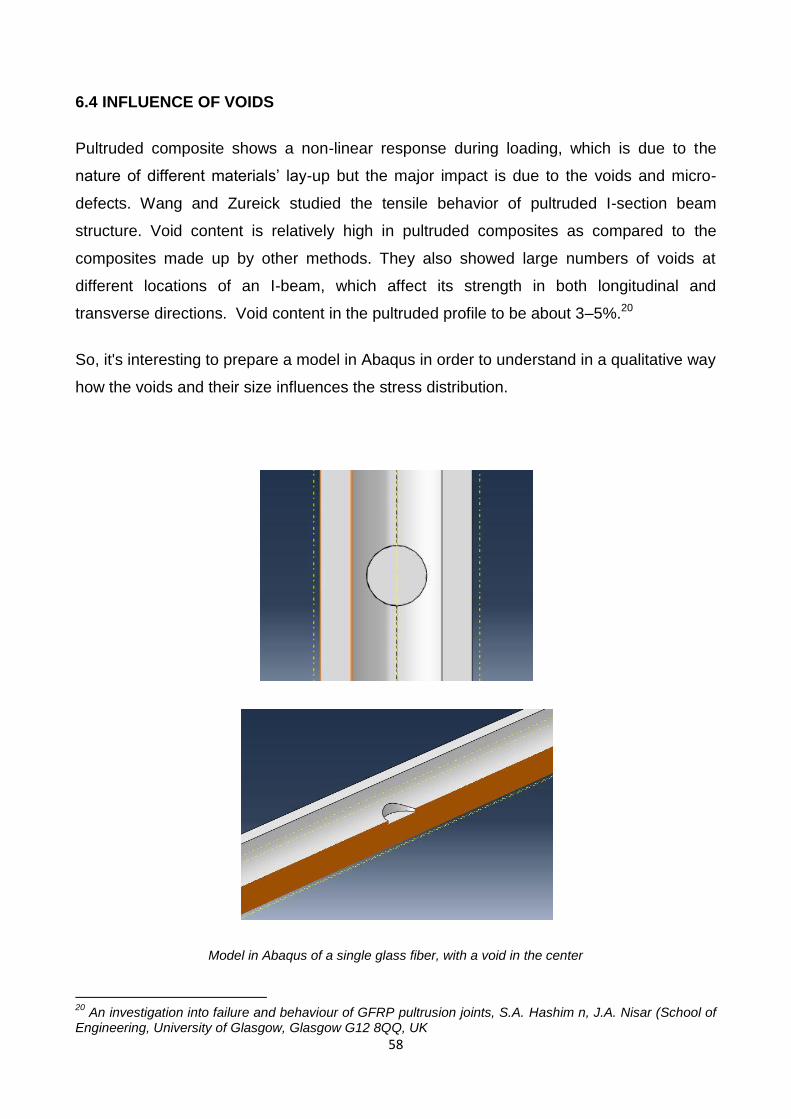
6.4 INFLUENCE OF VOIDS
Pultruded composite shows a non-linear response during loading, which is due to the
nature of different materials’ lay-up but the major impact is due to the voids and micro-
defects. Wang and Zureick studied the tensile behavior of pultruded I-section beam
structure. Void content is relatively high in pultruded composites as compared to the
composites made up by other methods. They also showed large numbers of voids at
different locations of an I-beam, which affect its strength in both longitudinal and
transverse directions. Void content in the pultruded profile to be about 3–5%.20
So, it's interesting to prepare a model in Abaqus in order to understand in a qualitative way
how the voids and their size influences the stress distribution.
Model in Abaqus of a single glass fiber, with a void in the center
20
An investigation into failure and behaviour of GFRP pultrusion joints, S.A. Hashim n, J.A. Nisar (School of Engineering, University of Glasgow, Glasgow G12 8QQ, UK
59
Distance No void 1 μm 3 μm 5 μm
0 μm 9.592626 10.98563 12 14.274159 Mpa
5.002594 μm 9.625012 10.95617 11.25087 11.269642 Mpa
10.00491 μm 9.597796 9.872651 9.952818 10.060838 Mpa
15.00748 μm 9.618526 10.29552 10.36074 10.408848 Mpa
20.01016 μm 9.672455 10.17067 10.22787 10.31088 Mpa
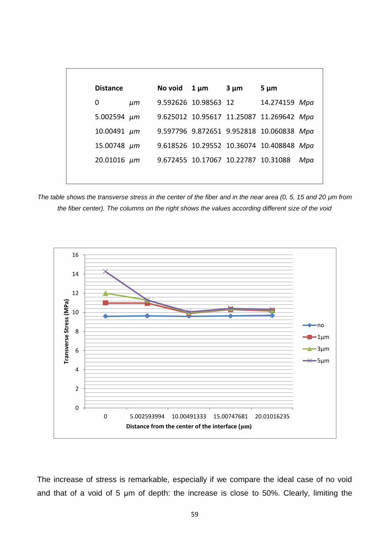
The table shows the transverse stress in the center of the fiber and in the near area (0, 5, 15 and 20 μm from
the fiber center). The columns on the right shows the values according different size of the void
The increase of stress is remarkable, especially if we compare the ideal case of no void
and that of a void of 5 μm of depth: the increase is close to 50%. Clearly, limiting the
0
2
4
6
8
10
12
14
16
0 5.002593994 10.00491333 15.00747681 20.01016235
Tran
sve
rse
Str
ess
(M
Pa)
Distance from the center of the interface (μm)
no
1μm
3μm
5μm

60
number and the size of the voids is a challenging topic, that requires further investigation.
The problem is about the big variations of temperature within the composite material
before, during and after the pultrusion process and more development about this could
increase a lot the strength of GFRP joints.
61
7. RESULTS AND DISCUSSIONS
7.1 COMPARING WITH PREVIOUS RESEARCHES
"It was mostly agreed that failure criteria often takes place due to transverse shear
and transverse tensile stresses. However, Nisar et al. and Lees et al. are more
inclined to suggest that the transverse tensile component is the main cause of
failure in bonded composite. The same view is shared by da Silva et al.who explain
that this is due to the low through thickness stiffness and low transverse tensile
strength."
The test seems to confirm this behavior of GFRP and actually the failure started
where the tensile stress is maximum.
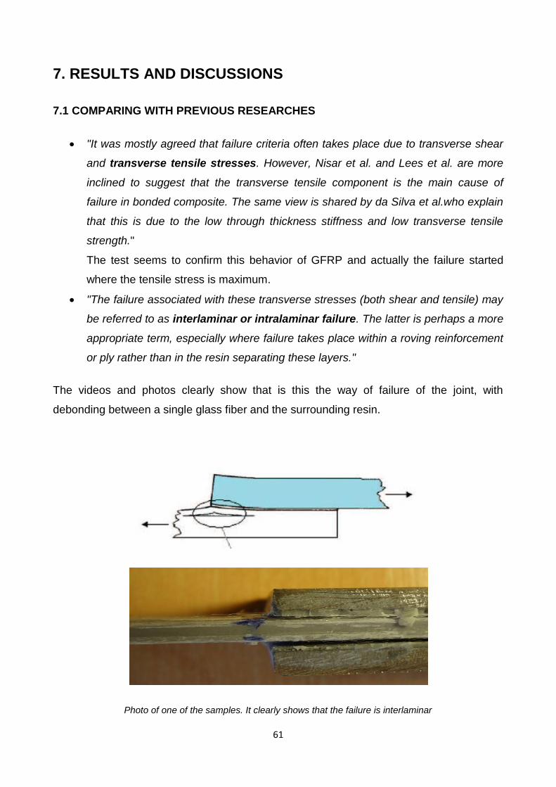
"The failure associated with these transverse stresses (both shear and tensile) may
be referred to as interlaminar or intralaminar failure. The latter is perhaps a more
appropriate term, especially where failure takes place within a roving reinforcement
or ply rather than in the resin separating these layers."
The videos and photos clearly show that is this the way of failure of the joint, with
debonding between a single glass fiber and the surrounding resin.
Photo of one of the samples. It clearly shows that the failure is interlaminar
62
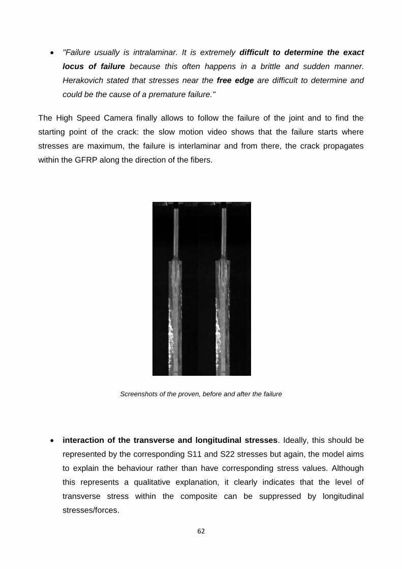
"Failure usually is intralaminar. It is extremely difficult to determine the exact
locus of failure because this often happens in a brittle and sudden manner.
Herakovich stated that stresses near the free edge are difficult to determine and
could be the cause of a premature failure."
The High Speed Camera finally allows to follow the failure of the joint and to find the
starting point of the crack: the slow motion video shows that the failure starts where
stresses are maximum, the failure is interlaminar and from there, the crack propagates
within the GFRP along the direction of the fibers.
Screenshots of the proven, before and after the failure
interaction of the transverse and longitudinal stresses. Ideally, this should be
represented by the corresponding S11 and S22 stresses but again, the model aims
to explain the behaviour rather than have corresponding stress values. Although
this represents a qualitative explanation, it clearly indicates that the level of
transverse stress within the composite can be suppressed by longitudinal
stresses/forces.

63
The test and especially the model in Abaqus seems to contradict this statement. In
laboratory, the failure started where the Tensile stress is maximum (where, according
previous theories, the presence of this stress should instead have a release-effect on the
transverse stress, which is the cause of the failure) but this doesn't necessarily implies that
this theory was wrong. What generates doubts is the Finite Element Model, which cleary
contradicts the idea that a tensile stress could be helpful in order to reduce transverse
stress and so increase the strength of the joint.
The graph shows that Tensile stress determines an increase of Transverse stress
0
2
4
6
8
10
12
0 10 50 100 200
Tran
sve
rse
Str
ess
[M
Pa]
Tensile Stress [MPa]
Influence of Tensile Stress on Transverse Stress
64
One explanation could be that applying a tensile stress makes the whole structure stiffer
and, even if the deformation is reduced and so apparently, transverse stresses too,
probably the increase of stiffness determines a local increase of stresses and this could
explain the trend of the second plot.
Clearly, this topic requires to be deepen and this represents a new challenge for
researchers in GFRP. To clarify this, it would be ideal to have a specific lab test to validate
these results, but unfortunately this test does not exist yet. So, continuing the work already
started at the University of Glasgow, the idea is to develop a new type of test in order to
understand how tensile stresses influence Transverse stress and so Transverse strength.
A test like this one could show which theory is correct and so enlarge the knowledge of
GFRP.
65
8. SCALE MODEL TEST
8.1 AIM OF THE SCALE MODEL
This test should allow to understand, at least in a qualitative way, the influence of Tensile
stress on Transverse stress. The question is if Tensile stress have a positive or negative
effect, releasing or increasing the transverse stress. For accomplishing this aim, the test
should follow some guideline in order to make it a valuable instrument for researchers, as:
Macro-Scale model: tests on the single fiber are incredibly expensive because they
require a lot of special instruments because the very small size of fibers (half of a
human hair);
Small size: smaller the size, closer the behavior of the sample will be to reality;
Ease of realization: the test should be design in order to be easily set for the test
and the replacement of the sample for a new test should be as quick as possible,
because to validate the data it is required a high number of proven (10-20);
Cheap: of course, it's important to constraint the costs more than possible;
Reproducibility: the test should be easily reproduced, not only in different times but
even in different labs, in order to allow comparison of data so to obtain results that
can be recognized by other researchers and institution.
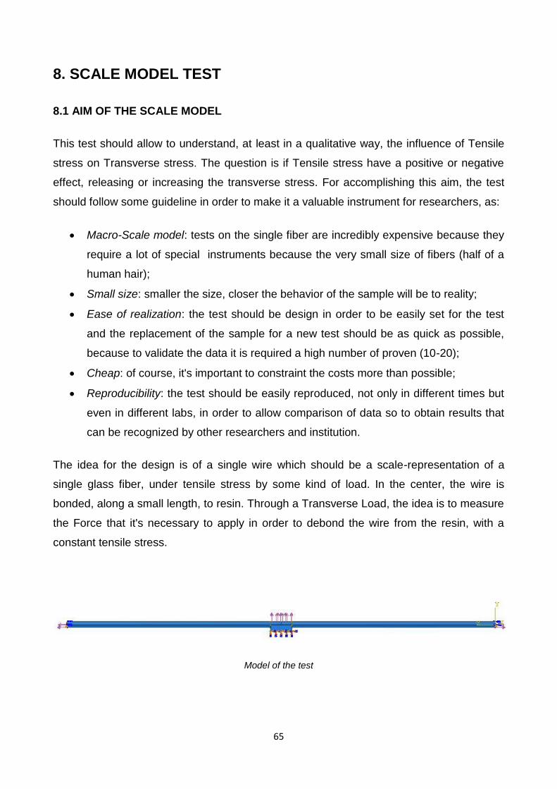
The idea for the design is of a single wire which should be a scale-representation of a
single glass fiber, under tensile stress by some kind of load. In the center, the wire is
bonded, along a small length, to resin. Through a Transverse Load, the idea is to measure
the Force that it's necessary to apply in order to debond the wire from the resin, with a
constant tensile stress.
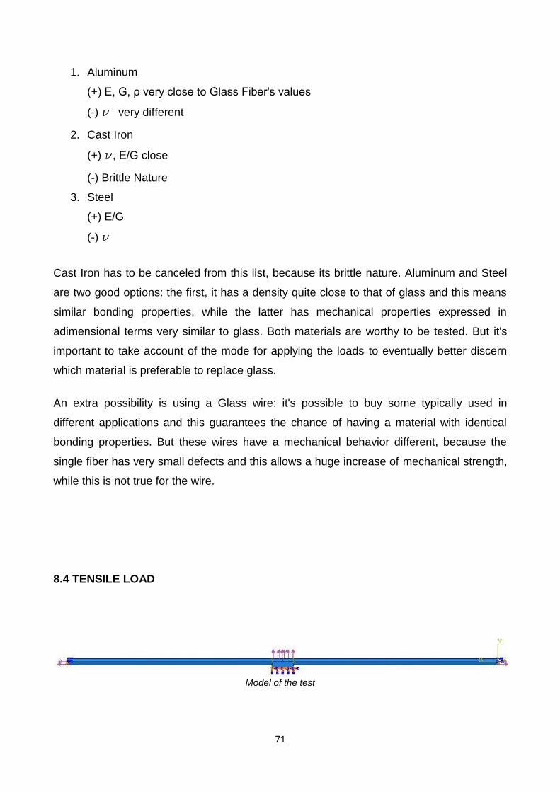
Model of the test

66
Model of the test (half structure)
8.2 SIMILITUDE AND DIMENSIONAL ANALYSIS
Similitude is a concept applicable to the testing of engineering models. A model is said to
have similitude with the real application if the two share geometric similarity, kinematic
similarity and dynamic similarity. Similarity and similitude are interchangeable in this
context. Similitude is therefore engineering Nomenclature.
The term dynamic similitude is often used as a catch-all because it implies that geometric
and kinematic similitude have already been met. Similitude's main application is in
hydraulic and aerospace engineering to test fluid flow conditions with scaled models. It is
also the primary theory behind many textbook formulas in fluid mechanics.
Engineering models are used to study complex fluid dynamics problems where
calculations and computer simulations aren't reliable. Models are usually smaller than the
final design, but not always. Scale models allow testing of a design prior to building, and in
many cases are a critical step in the development process.
Construction of a scale model, however, must be accompanied by an analysis to
determine what conditions it is tested under. While the geometry may be simply scaled,
other parameters, such as pressure, temperature or the velocity and type of fluid may
need to be altered. Similitude is achieved when testing conditions are created such that
the test results are applicable to the real design. The following criteria are required to
achieve similitude;
1) Geometric similarity – The model is the same shape as the application, usually
scaled.
67
2) Kinematic similarity – Fluid flow of both the model and real application must
undergo similar time rates of change motions. (fluid streamlines are similar)
3) Dynamic similarity – Ratios of all forces acting on corresponding fluid particles and
boundary surfaces in the two systems are constant.
To satisfy the above conditions the application is analyzed; All parameters required to
describe the system are identified using principles from continuum mechanics.
Dimensional analysis is used to express the system with as few independent variables and
as many dimensionless parameters as possible.
The values of the dimensionless parameters are held to be the same for both the scale
model and application. This can be done because they are dimensionless and will ensure
dynamic similitude between the model and the application. The resulting equations are
used to derive scaling laws which dictate model testing conditions.
It is often impossible to achieve strict similitude during a model test. The greater the
departure from the application's operating conditions, the more difficult achieving similitude
is. In these cases some aspects of similitude may be neglected, focusing on only the most
important parameters.
The design of marine vessels remains more of an art than a science in large part because
dynamic similitude is especially difficult to attain for a vessel that is partially submerged: a
ship is affected by wind forces in the air above it, by hydrodynamic forces within the water
under it, and especially by wave motions at the interface between the water and the air.
The scaling requirements for each of these phenomena differ, so models cannot replicate
what happens to a full sized vessel nearly so well as can be done for an aircraft or
submarine—each of which operates entirely within one medium.
Similitude is a term used widely in fracture mechanics relating to the strain life approach.
Under given loading conditions the fatigue damage in an un-notched specimen is
comparable to that of a notched specimen. Similitude suggests that the component fatigue
life of the two objects will also be similar.21
21
from Wikipedia: http://en.wikipedia.org/wiki/Similitude_(model)
68
The theory of Similitude allows to create a scale model of a single glass fiber, test it in
laboratory and obtaining data which are valid even for the micro-model. The first step is to
find all the variables that are interesting for this application:
Geometric Variables: D (diameter), L* (Length of the portion of fiber)
Material Variables: E (Young's Modulus), ρ (density), G (Shear Modulus), ν
(Poisson's Ratio)
Dynamic Variables: F1 (Tensile Force), F2 (Transverse Force)
Then, let's express every variable according the fundamental dimension: Length (L), Mass
(M) and Time (T) (Temperature and other dimensions are not interesting in this
application).
D=[L]
E=[M L-1 T-2]
G=[M L-1 T-2]
F=[M L T-2]
L*=[L]
ρ=[M L-3]
ν =[1]
Using the Dimensional analysis, it's possible to find some Adimensional Number that will
allow the application of Similitude. It's very easy to show that these adimensional group
are:
1) π1=
2) π2=
where is the stress
3) π3=ν
4) π4=
= 2(1+ ν)
Because ν depends on E and G, the fourth group is redundant.
Now, we can consider a small portion of glass fiber:
69
0.1 mm long
16 μm of diameter
E=72-85 GPa
G=30-36 GPa
ν =0.22
So,
π1=
=
= 6.25
π2=
π3=ν=0.22
π4=
=
= 2.42
These adimensional numbers allows finding possible materials that can replace glass fiber
in the experimentation. π1 gives the correlation between reality and the macro-scale
model's geometry.
8.3 MATERIALS
To find materials suitable for our experimentation to replace glass fiber, CES EduPack
2012 is an interesting resource for studying about materials, thanks to its huge database of
materials and process. The database has three different levels (introductory, intermediate
and advance level) and covers a wide range of materials (more than 3000). For every
material or process, there is a very useful explanation, with text, images and all the most
important properties (technical, economical, eco properties). The presence of "interactive
materials properties chart" allows us to compare properties and select the most suitable
material or process, in an easy and very intuitive way. The database is helpful to
understand the relationship between materials and properties and is a good source about
references, to find the right book to deepen the knowledge of a specific topic.
70
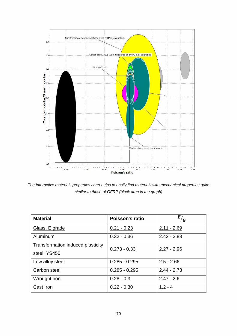
The Interactive materials properties chart helps to easily find materials with mechanical properties quite
similar to those of GFRP (black area in the graph)
Material Poisson's ratio
Glass, E grade 0.21 - 0.23 2.11 - 2.69
Aluminum 0.32 - 0.36 2.42 - 2.88
Transformation induced plasticity
steel, YS450 0.273 - 0.33 2.27 - 2.96
Low alloy steel 0.285 - 0.295 2.5 - 2.66
Carbon steel 0.285 - 0.295 2.44 - 2.73
Wrought iron 0.28 - 0.3 2.47 - 2.6
Cast Iron 0.22 - 0.30 1.2 - 4
71
1. Aluminum
(+) E, G, ρ very close to Glass Fiber's values
(-) ν very different
2. Cast Iron
(+) ν, E/G close
(-) Brittle Nature
3. Steel
(+) E/G
(-) ν
Cast Iron has to be canceled from this list, because its brittle nature. Aluminum and Steel
are two good options: the first, it has a density quite close to that of glass and this means
similar bonding properties, while the latter has mechanical properties expressed in
adimensional terms very similar to glass. Both materials are worthy to be tested. But it's
important to take account of the mode for applying the loads to eventually better discern
which material is preferable to replace glass.
An extra possibility is using a Glass wire: it's possible to buy some typically used in
different applications and this guarantees the chance of having a material with identical
bonding properties. But these wires have a mechanical behavior different, because the
single fiber has very small defects and this allows a huge increase of mechanical strength,
while this is not true for the wire.
8.4 TENSILE LOAD
Model of the test

72
The easiest way is to use a weight and its weight-force in order to have a tensile stress.
Scheme of the test
The idea is to apply simultaneously a tensile and transverse stress. The wire is bonded to
a small quantity of resin (area with slanting), with one end fixed (encastré) and the other
attached to a weight that applies the tensile stress.
8.5 TRANSVERSE LOAD
The biggest problem is to find a good way in order to apply the vertical load. This choice is
very important and it can influence the type of material for the test.
Several options have been taken in consideration:
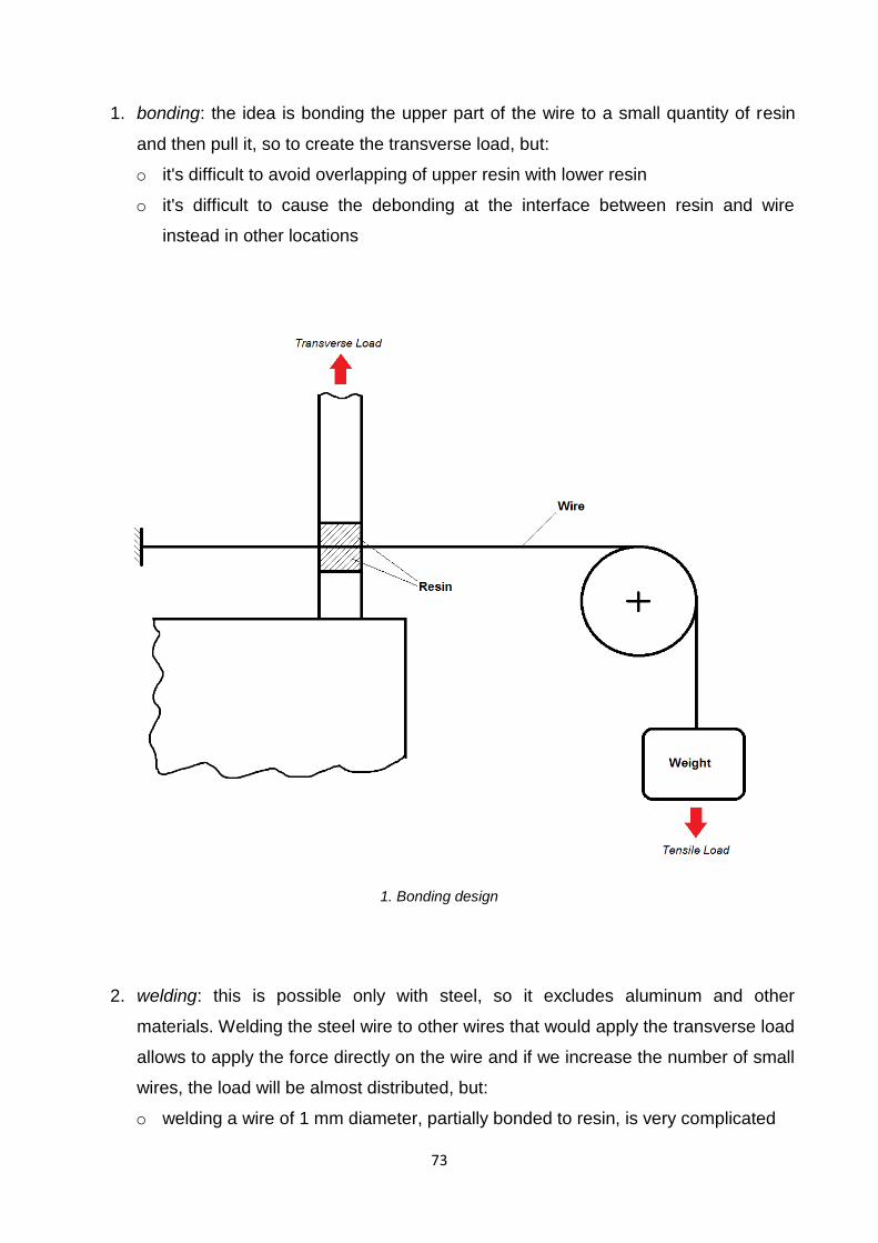
73
1. bonding: the idea is bonding the upper part of the wire to a small quantity of resin
and then pull it, so to create the transverse load, but:
o it's difficult to avoid overlapping of upper resin with lower resin
o it's difficult to cause the debonding at the interface between resin and wire
instead in other locations
1. Bonding design
2. welding: this is possible only with steel, so it excludes aluminum and other
materials. Welding the steel wire to other wires that would apply the transverse load
allows to apply the force directly on the wire and if we increase the number of small
wires, the load will be almost distributed, but:
o welding a wire of 1 mm diameter, partially bonded to resin, is very complicated
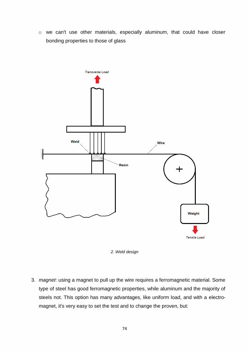
74
o we can't use other materials, especially aluminum, that could have closer
bonding properties to those of glass
2. Weld design
3. magnet: using a magnet to pull up the wire requires a ferromagnetic material. Some
type of steel has good ferromagnetic properties, while aluminum and the majority of
steels not. This option has many advantages, like uniform load, and with a electro-
magnet, it's very easy to set the test and to change the proven, but:
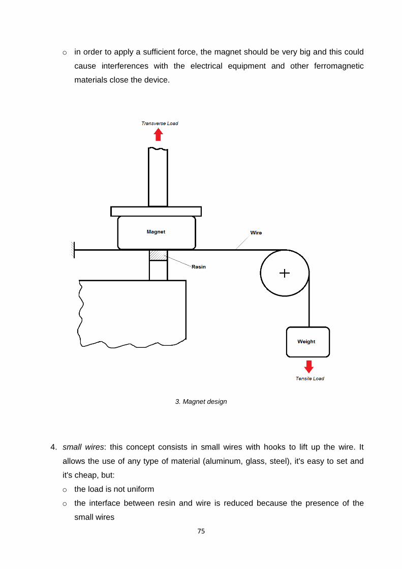
75
o in order to apply a sufficient force, the magnet should be very big and this could
cause interferences with the electrical equipment and other ferromagnetic
materials close the device.
3. Magnet design
4. small wires: this concept consists in small wires with hooks to lift up the wire. It
allows the use of any type of material (aluminum, glass, steel), it's easy to set and
it's cheap, but:
o the load is not uniform
o the interface between resin and wire is reduced because the presence of the
small wires
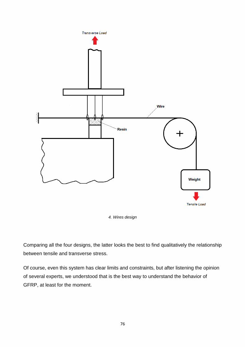
76
4. Wires design
Comparing all the four designs, the latter looks the best to find qualitatively the relationship
between tensile and transverse stress.
Of course, even this system has clear limits and constraints, but after listening the opinion
of several experts, we understood that is the best way to understand the behavior of
GFRP, at least for the moment.
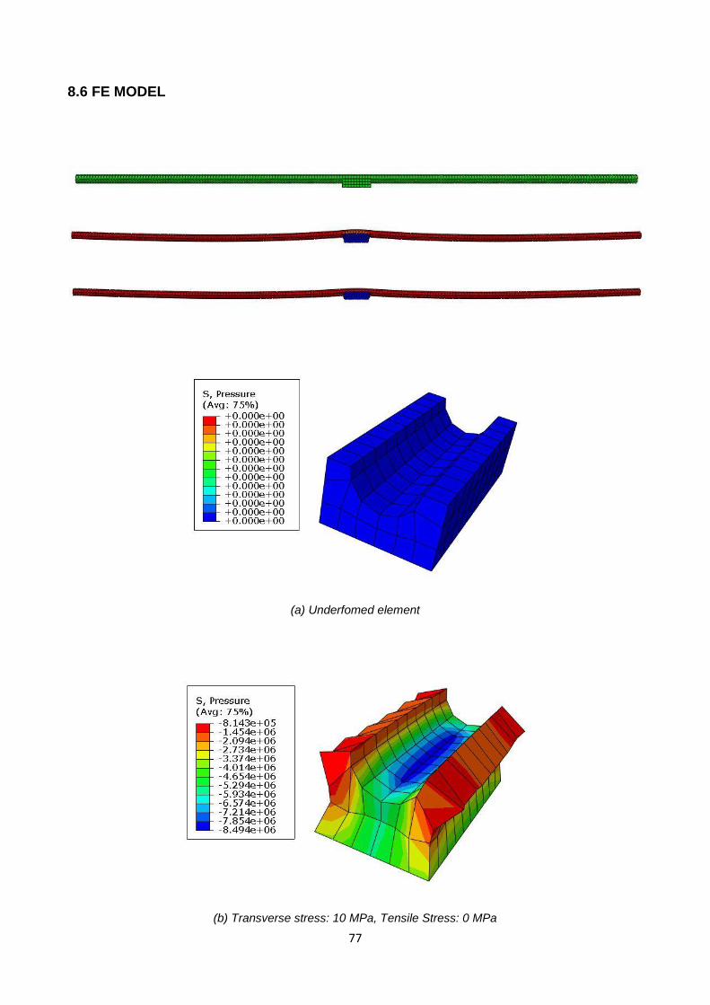
77
8.6 FE MODEL
(a) Underfomed element
(b) Transverse stress: 10 MPa, Tensile Stress: 0 MPa
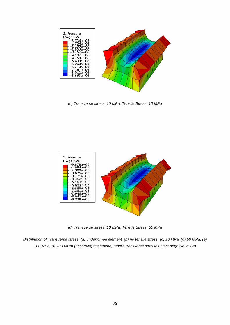
78
(c) Transverse stress: 10 MPa, Tensile Stress: 10 MPa
(d) Transverse stress: 10 MPa, Tensile Stress: 50 MPa
Distribution of Transverse stress: (a) underfomed element, (b) no tensile stress, (c) 10 MPa, (d) 50 MPa, (e)
100 MPa, (f) 200 MPa) (according the legend, tensile transverse stresses have negative value)
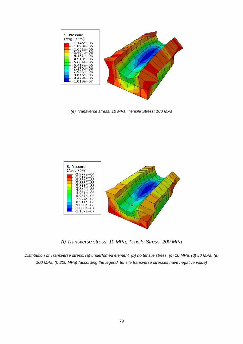
79
(e) Transverse stress: 10 MPa, Tensile Stress: 100 MPa
(f) Transverse stress: 10 MPa, Tensile Stress: 200 MPa
Distribution of Transverse stress: (a) underfomed element, (b) no tensile stress, (c) 10 MPa, (d) 50 MPa, (e)
100 MPa, (f) 200 MPa) (according the legend, tensile transverse stresses have negative value)

80
The distribution of Transverse stress along the interface between resin and glass fiber
Influence of Tensile stress on Transverse stress. The values refer to the center of the interface (normalized
distance x=0.5), where the transverse stress is maximum
0
2
4
6
8
10
12
14 Tr
ansv
ers
e s
tre
ss
Normalized distance
Transverse Stress
0 Mpa
10 Mpa
50 Mpa
100 Mpa
200 Mpa
Tensile stress
0
2
4
6
8
10
12
14
0 10 50 100 200
Tran
sve
rse
Str
ess
[M
Pa]
Tensile Stress [MPa]
Influence of Tensile stress on Transverse stress at x=0.5

81
The Abaqus study agrees with the previous results. Realizing this test in laboratory could
allow to convalidate the Finite Element Model, or not. In both cases, this would be a small
leap forward about the knowledge of GFRP and their behavior, giving us the chance to
develop more efficient joints and designs, with great impact on a vast variety of
applications.
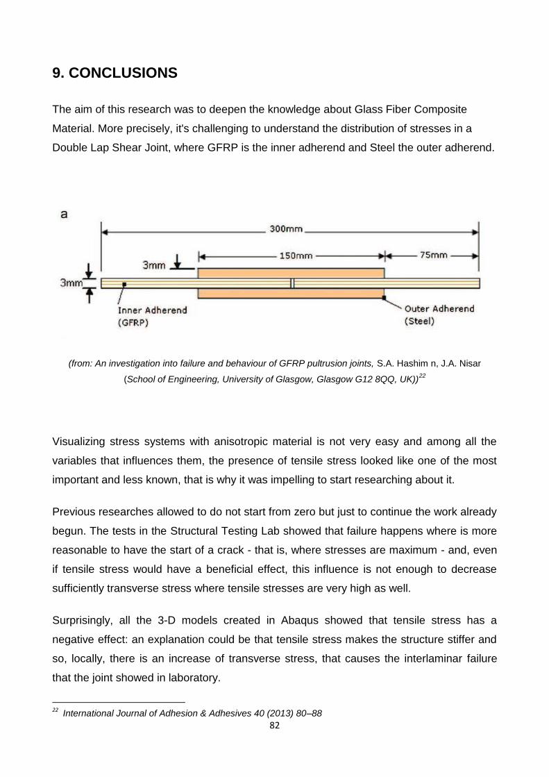
82
9. CONCLUSIONS
The aim of this research was to deepen the knowledge about Glass Fiber Composite
Material. More precisely, it's challenging to understand the distribution of stresses in a
Double Lap Shear Joint, where GFRP is the inner adherend and Steel the outer adherend.
(from: An investigation into failure and behaviour of GFRP pultrusion joints, S.A. Hashim n, J.A. Nisar
(School of Engineering, University of Glasgow, Glasgow G12 8QQ, UK))22
Visualizing stress systems with anisotropic material is not very easy and among all the
variables that influences them, the presence of tensile stress looked like one of the most
important and less known, that is why it was impelling to start researching about it.
Previous researches allowed to do not start from zero but just to continue the work already
begun. The tests in the Structural Testing Lab showed that failure happens where is more
reasonable to have the start of a crack - that is, where stresses are maximum - and, even
if tensile stress would have a beneficial effect, this influence is not enough to decrease
sufficiently transverse stress where tensile stresses are very high as well.
Surprisingly, all the 3-D models created in Abaqus showed that tensile stress has a
negative effect: an explanation could be that tensile stress makes the structure stiffer and
so, locally, there is an increase of transverse stress, that causes the interlaminar failure
that the joint showed in laboratory.
22
International Journal of Adhesion & Adhesives 40 (2013) 80–88

83
Only new empirical tests can reveal what model is right. This is probably a challenging
topic to deepen and study, and for this reason it has been designed a new type of
mechanical test that can bring some light on this problem.
84
10. REFERENCES
Nisar JA, Hashim SA. Meso-scale laminate adhesive joints for pultrusions. Int JAdhes
Adhes 2010;30:763–73.
Hashim SA. Strength of resin coated adhesive bonded double lap-shear pultrusion joints at
ambient temperature. Int J Adhes Adhes 2009;29:294–301.
J.E. Gordon. Structures: Or Why Things Don't Fall Down. 1978
Brady M. Walther. An Investigation of the Tensile Strength and Stiffness of Unidirectional
Polymer-Matrix, Carbon-Fiber Composites under the Influence of Elevated Temperatures.
1998
prof. Michele Anatone. Adimensional Analysis and Similitude theory, notes from the course
"Macchine 2". Università degli studi dell'Aquila. 2012
Nisar JA, Modelling the interfaces of bondable pultrusions, PhD thesis, University of
Glasgow; 2011.
Wikipedia. Glass Fiber Composite Materials. (http://en.wikipedia.org/wiki/Fiberglass)
Wikipedia. Adhesive. (http://en.wikipedia.org/wiki/Adhesive)
Granta Design. CES EduPack 2012's Materials database
Christopher Wonderlya, Joachim Grenestedt, Go¨ran Fernlund, Elvis Ceˇpus. Comparison
of mechanical properties of glass fiber/vinyl ester and carbon fiber/vinyl ester composites.
Composites: Part B 36 (2005) 417–426
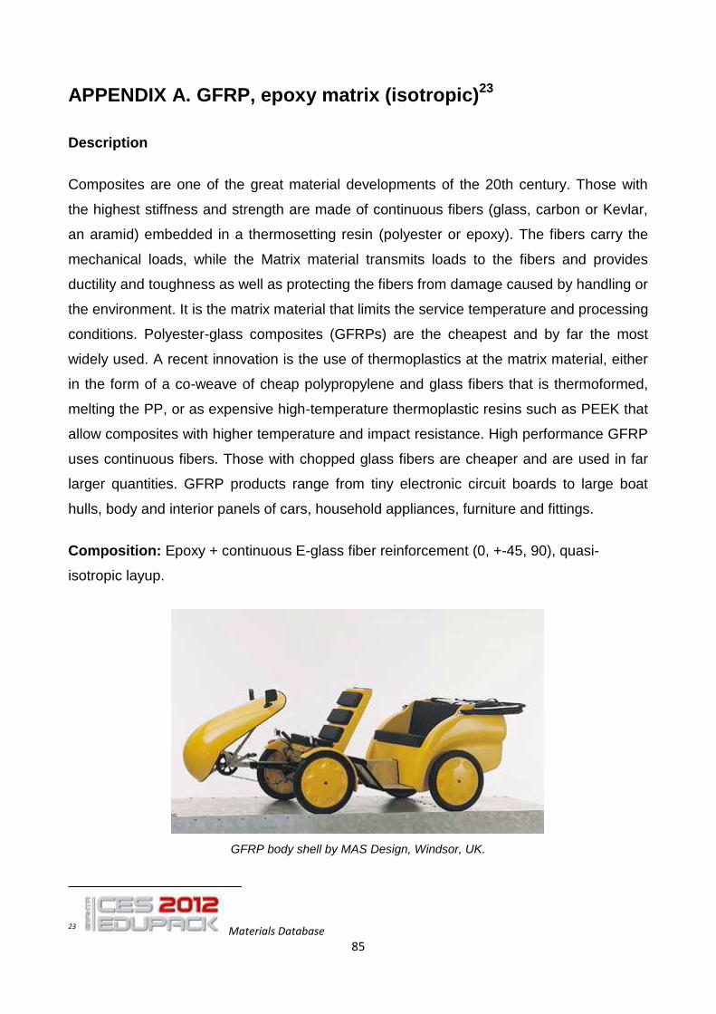
85
APPENDIX A. GFRP, epoxy matrix (isotropic)23
Description
Composites are one of the great material developments of the 20th century. Those with
the highest stiffness and strength are made of continuous fibers (glass, carbon or Kevlar,
an aramid) embedded in a thermosetting resin (polyester or epoxy). The fibers carry the
mechanical loads, while the Matrix material transmits loads to the fibers and provides
ductility and toughness as well as protecting the fibers from damage caused by handling or
the environment. It is the matrix material that limits the service temperature and processing
conditions. Polyester-glass composites (GFRPs) are the cheapest and by far the most
widely used. A recent innovation is the use of thermoplastics at the matrix material, either
in the form of a co-weave of cheap polypropylene and glass fibers that is thermoformed,
melting the PP, or as expensive high-temperature thermoplastic resins such as PEEK that
allow composites with higher temperature and impact resistance. High performance GFRP
uses continuous fibers. Those with chopped glass fibers are cheaper and are used in far
larger quantities. GFRP products range from tiny electronic circuit boards to large boat
hulls, body and interior panels of cars, household appliances, furniture and fittings.
Composition: Epoxy + continuous E-glass fiber reinforcement (0, +-45, 90), quasi-
isotropic layup.
GFRP body shell by MAS Design, Windsor, UK.
23 Materials Database
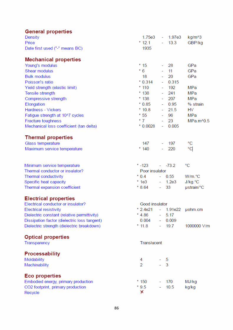
86
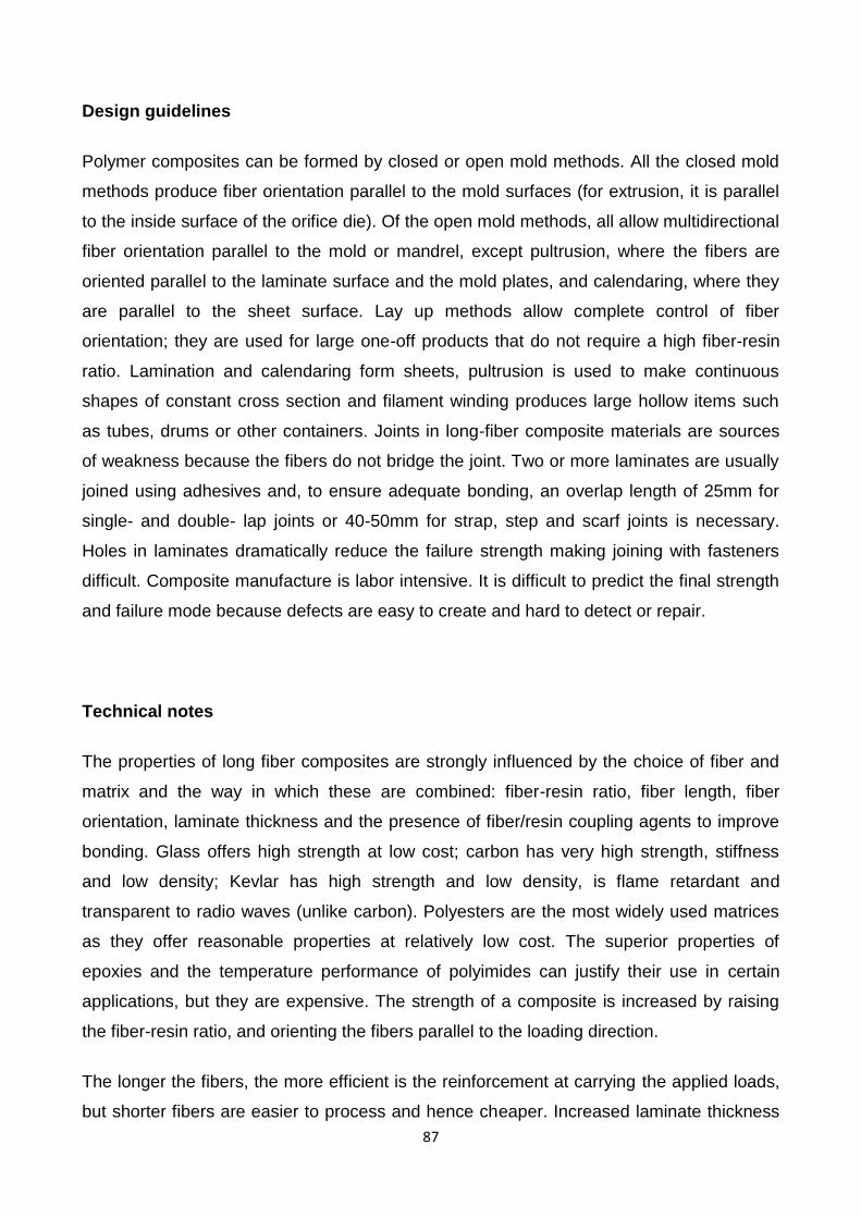
87
Design guidelines
Polymer composites can be formed by closed or open mold methods. All the closed mold
methods produce fiber orientation parallel to the mold surfaces (for extrusion, it is parallel
to the inside surface of the orifice die). Of the open mold methods, all allow multidirectional
fiber orientation parallel to the mold or mandrel, except pultrusion, where the fibers are
oriented parallel to the laminate surface and the mold plates, and calendaring, where they
are parallel to the sheet surface. Lay up methods allow complete control of fiber
orientation; they are used for large one-off products that do not require a high fiber-resin
ratio. Lamination and calendaring form sheets, pultrusion is used to make continuous
shapes of constant cross section and filament winding produces large hollow items such
as tubes, drums or other containers. Joints in long-fiber composite materials are sources
of weakness because the fibers do not bridge the joint. Two or more laminates are usually
joined using adhesives and, to ensure adequate bonding, an overlap length of 25mm for
single- and double- lap joints or 40-50mm for strap, step and scarf joints is necessary.
Holes in laminates dramatically reduce the failure strength making joining with fasteners
difficult. Composite manufacture is labor intensive. It is difficult to predict the final strength
and failure mode because defects are easy to create and hard to detect or repair.
Technical notes
The properties of long fiber composites are strongly influenced by the choice of fiber and
matrix and the way in which these are combined: fiber-resin ratio, fiber length, fiber
orientation, laminate thickness and the presence of fiber/resin coupling agents to improve
bonding. Glass offers high strength at low cost; carbon has very high strength, stiffness
and low density; Kevlar has high strength and low density, is flame retardant and
transparent to radio waves (unlike carbon). Polyesters are the most widely used matrices
as they offer reasonable properties at relatively low cost. The superior properties of
epoxies and the temperature performance of polyimides can justify their use in certain
applications, but they are expensive. The strength of a composite is increased by raising
the fiber-resin ratio, and orienting the fibers parallel to the loading direction.
The longer the fibers, the more efficient is the reinforcement at carrying the applied loads,
but shorter fibers are easier to process and hence cheaper. Increased laminate thickness

88
leads to reduced composite strength and modulus as there is an increased likelihood of
entrapped voids. Coupling agents generally increase tensile strength. Environmental
conditions affect the performance of composites: fatigue loading, moisture and heat all
reduce allowable strength.
Typical uses
Sports equipment such as skis, racquets, skate boards and golf club shafts, ship and boat
hulls; body shells; automobile components; cladding and fittings in construction; chemical
plant.
Tradenames
Cycom, Fiberdux, Scotchply

89
APPENDIX B. Photron Fastcam-SA3 High Speed Camera
The Pool has two Photron Fastcam SA-3 monochrome systems. They can record at up to
120,000 fps. They use a CMOS sensor with a maximum resolution of 1024 x 1024 (17μ)
pixels at up to 2,000 fps. Above 2,000 fps, the resolution decreases. Please see tables
below showing the different resolutions available at different speeds.
Recording time can be increased by reducing the resolution. Triggering is possible via
switch closure or TTL. Control is by the supplied PC which is dual core 2.4GHz, 2 GB
RAM, 250 GB hard drive and 19” flat screen monitor. The system runs under win XP pro
and is fitted with a DVD writer. The PC is connected to the camera processor via a 10
metre Gigabit Ethernet cable. A 500GB external USB hard drive is supplied, allowing files
to be easily moved to the users PC.
Recording modes available are: Start, Centre, End, Manual, Random, Random
Reset, Random Centre, Random Manual and Dual Speed Recording.
Shutter speeds between 16.7ms and 2μs are available
The camera can accept any Nikon or C-Mount lens. We supply a Nikon 24-85mm
f2.8 zoom lens..
Images can be saved as JPEG, AVI, TIF, BMP, RAW, PNG and FTIF
Frame rate/ Resolution table:
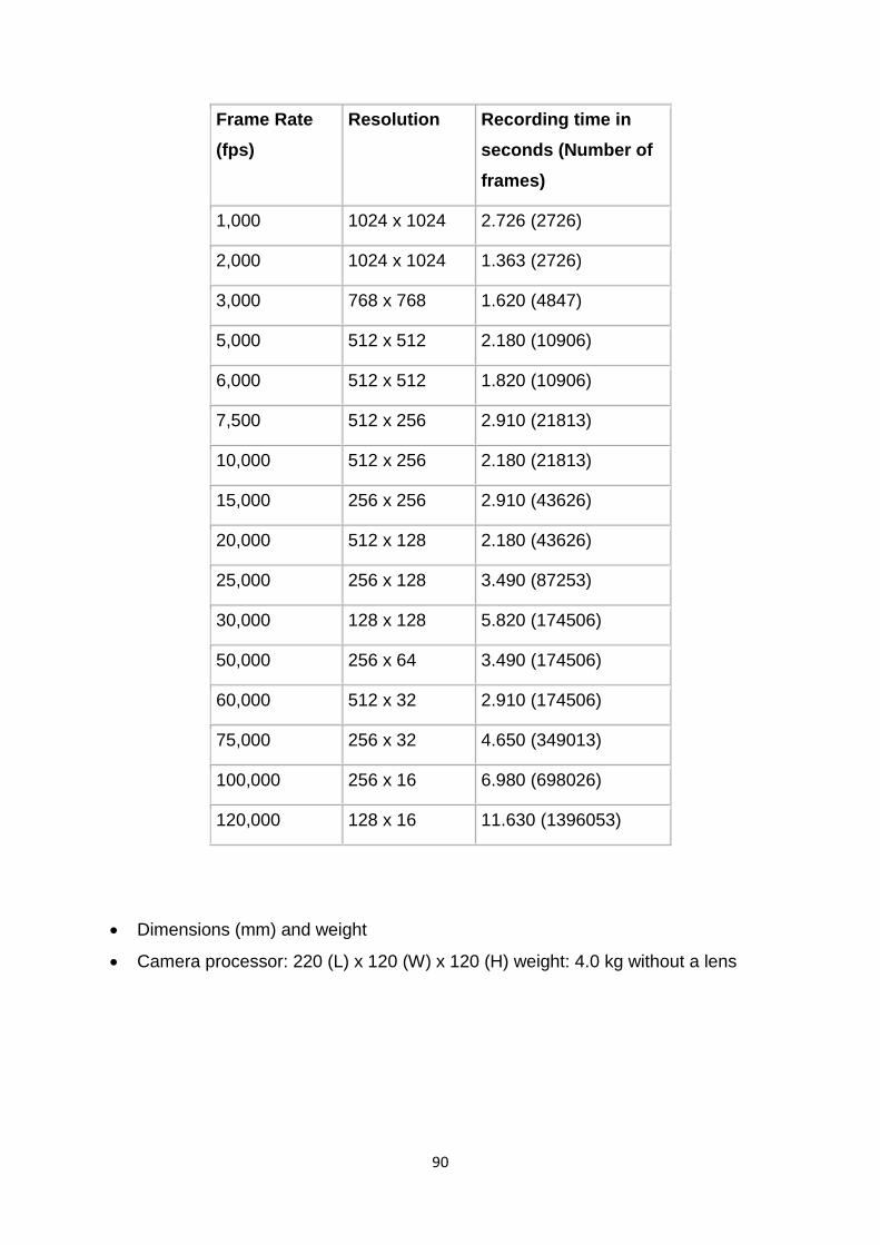
90
Frame Rate
(fps)
Resolution Recording time in
seconds (Number of
frames)
1,000 1024 x 1024 2.726 (2726)
2,000 1024 x 1024 1.363 (2726)
3,000 768 x 768 1.620 (4847)
5,000 512 x 512 2.180 (10906)
6,000 512 x 512 1.820 (10906)
7,500 512 x 256 2.910 (21813)
10,000 512 x 256 2.180 (21813)
15,000 256 x 256 2.910 (43626)
20,000 512 x 128 2.180 (43626)
25,000 256 x 128 3.490 (87253)
30,000 128 x 128 5.820 (174506)
50,000 256 x 64 3.490 (174506)
60,000 512 x 32 2.910 (174506)
75,000 256 x 32 4.650 (349013)
100,000 256 x 16 6.980 (698026)
120,000 128 x 16 11.630 (1396053)
Dimensions (mm) and weight
Camera processor: 220 (L) x 120 (W) x 120 (H) weight: 4.0 kg without a lens