Embed Size (px)
Citation preview
FINITE ELEMENT MODELLING RESEARCH GROUP (FEMRG)
Labo Soete, Faculty of Engineering and Architecture, Ghent University
http://www.finiteelementresearch.ugent.be/
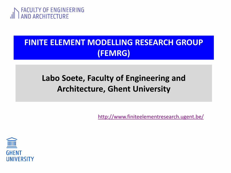
Staff
Head of Research Group: Prof. dr. ir. Magd Abdel Wahab
Full time Researchers:Dr. Yong Ling, Vu Huu Truong, Samir Khatir, Dang Bao Loi, Hau Ngoc Nguyen, Truong Phuong, Shengjie Wang, Qingming Deng, HoaTran, Huong Duong Nguyen, Ho Viet Long, Tran HieuNguyen, Roumaissa Zenzen, Duy Khuong Nguyen
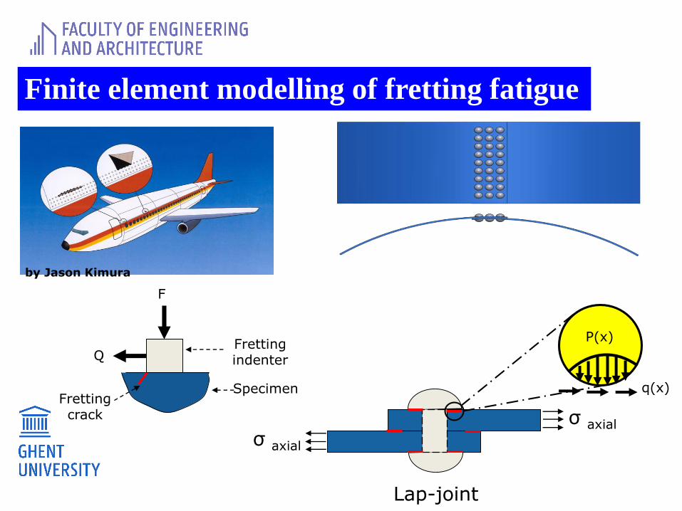
Finite element modelling of fretting fatigue
SpecimenFretting crack
Fretting indenterQ
F
P(x)
q(x)
σ axial
σ axial
Lap-joint
by Jason Kimura
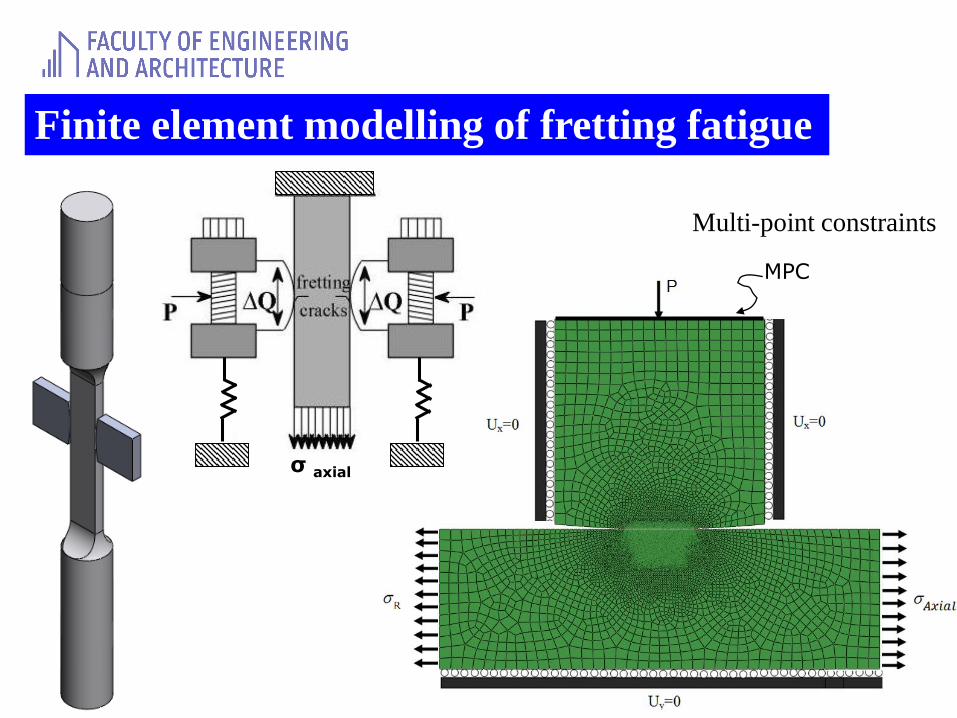
Finite element modelling of fretting fatigue
MPC
σ axial
Multi-point constraints
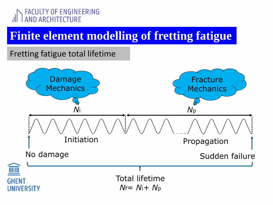
Finite element modelling of fretting fatigue
Fretting fatigue total lifetime
Ni
No damage
Total lifetime Nf= Ni+ Np
Sudden failure
Np
DamageMechanics
Fracture Mechanics
Initiation Propagation
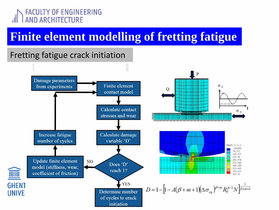
Finite element modelling of fretting fatigue
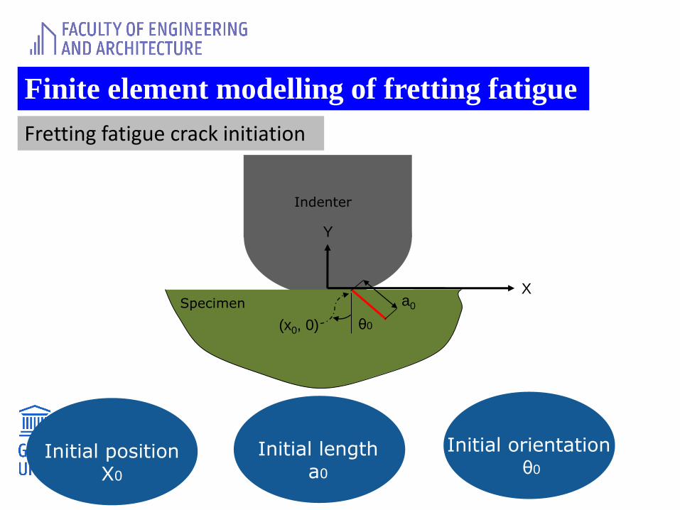
Fretting fatigue crack initiation
Finite element modelling of fretting fatigue
Fretting fatigue crack initiation
Initial positionX0
Initial lengtha0
Initial orientationθ0
Specimen
Indenter
θ0
a0
(x0, 0)
X
Y
Finite element modelling of fretting fatigue
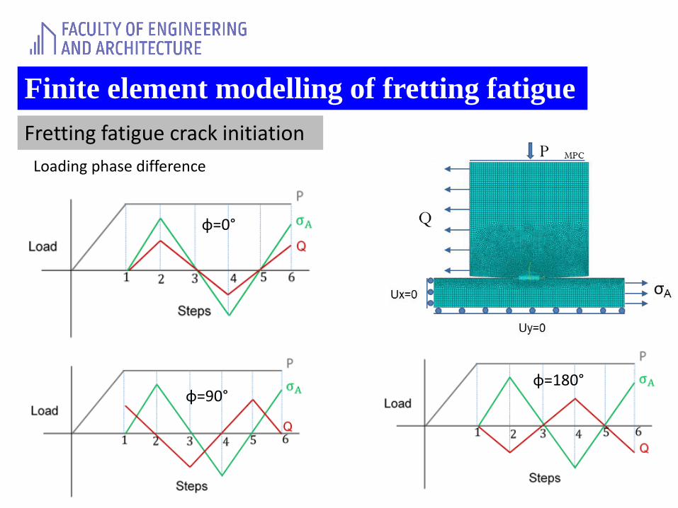
Fretting fatigue crack initiation
Loading phase difference
φ=0°
φ=180°φ=90°
Finite element modelling of fretting fatigue
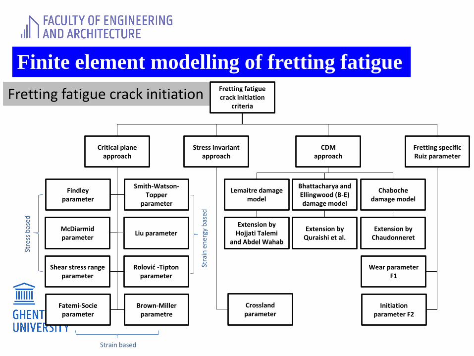
Fretting fatigue crack initiationFretting fatigue crack initiation
criteria
Critical plane approach
Stress invariant approach
CDMapproach
Fretting specific Ruiz parameter
Smith-Watson-Topper
parameter
Findley parameter
Liu parameterMcDiarmidparameter
Rolović -Tipton parameter
Shear stress range parameter
Brown-Miller parametre
Fatemi-Socieparameter
Crosslandparameter
Lemaitre damage model
Bhattacharya and Ellingwood (B-E) damage model
Initiation parameter F2
Stre
ss b
ased
Stra
in e
ner
gy b
ased
Strain based
Wear parameter F1
Chabochedamage model
Extension by Hojjati Talemi
and Abdel Wahab
Extension by Quraishi et al.
Extension by Chaudonneret
Finite element modelling of fretting fatigue
Fretting fatigue crack initiation
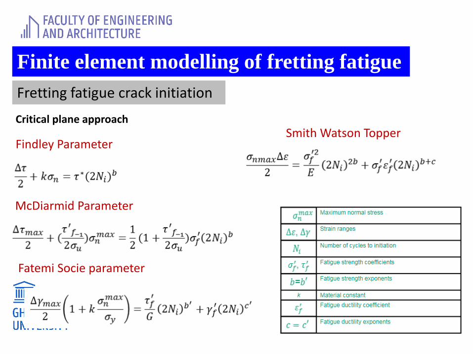
Critical plane approach
Findley Parameter
McDiarmid Parameter
Smith Watson Topper
Fatemi Socie parameter
Finite element modelling of fretting fatigue
Fretting fatigue crack initiation
Critical plane approach
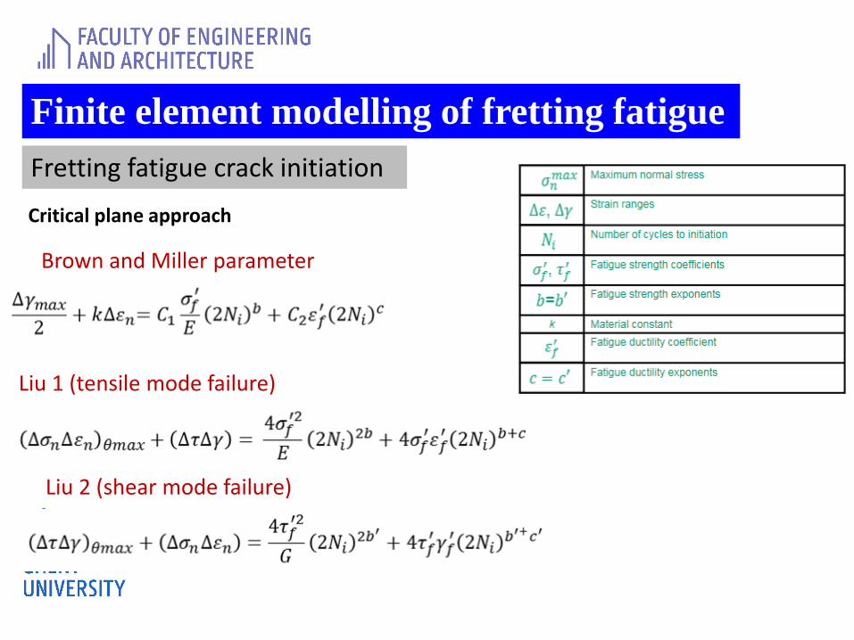
Brown and Miller parameter
Liu 1 (tensile mode failure)
Liu 2 (shear mode failure)
Finite element modelling of fretting fatigue
Fretting fatigue crack initiation
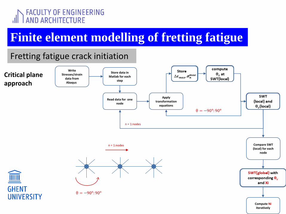
Critical plane approach
Write Stresses/strain
data from Abaqusr
Store data in Matlab for each
step
Read data for one node
Apply transformation
equations
Compare SWT (local) for each
node
n = 1:nodes
n = 1:nodes
Compute Niiteratively
Finite element modelling of fretting fatigue
Fretting fatigue crack initiation
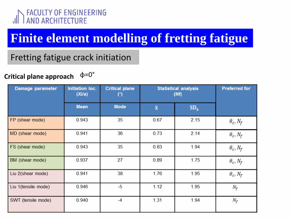
Critical plane approach φ=0°
Finite element modelling of fretting fatigue
Fretting fatigue crack initiation
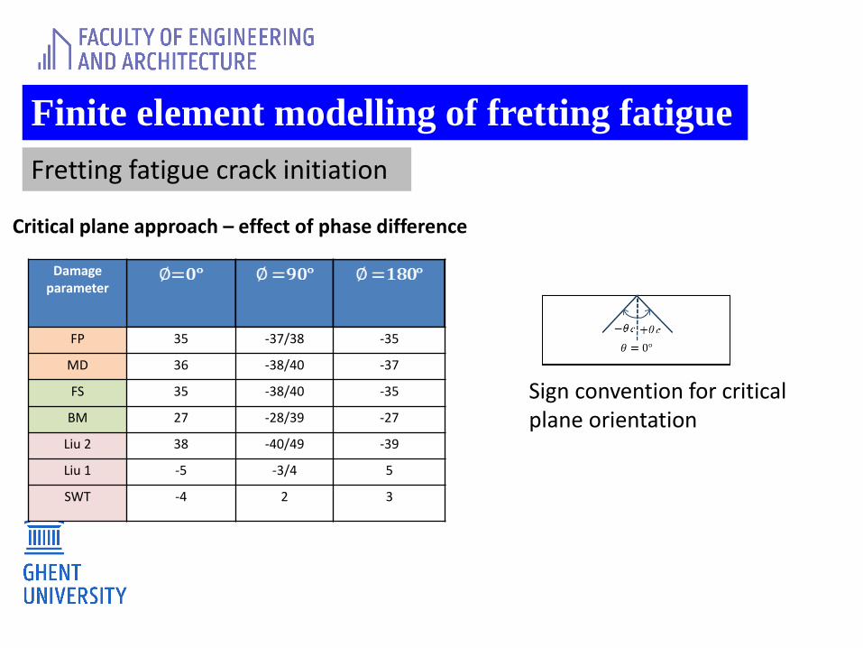
Critical plane approach – effect of phase difference
Damage parameter
FP 35 -37/38 -35
MD 36 -38/40 -37
FS 35 -38/40 -35
BM 27 -28/39 -27
Liu 2 38 -40/49 -39
Liu 1 -5 -3/4 5
SWT -4 2 3
Sign convention for critical plane orientation
Finite element modelling of fretting fatigue
Fretting fatigue crack initiation
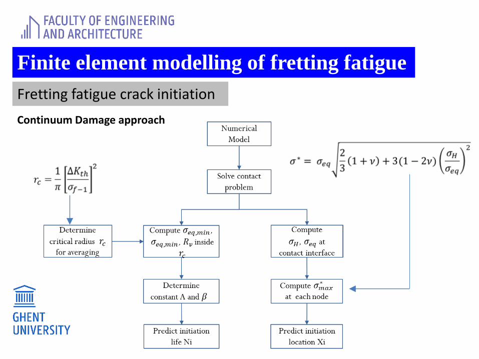
Continuum Damage approach

Finite element modelling of fretting fatigue
Fretting fatigue crack initiation
Continuum Damage approach
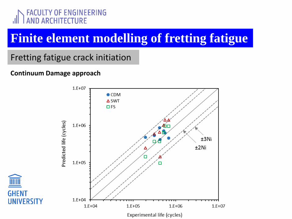
Finite element modelling of fretting fatigue
Fretting fatigue crack initiation
Continuum Damage approach
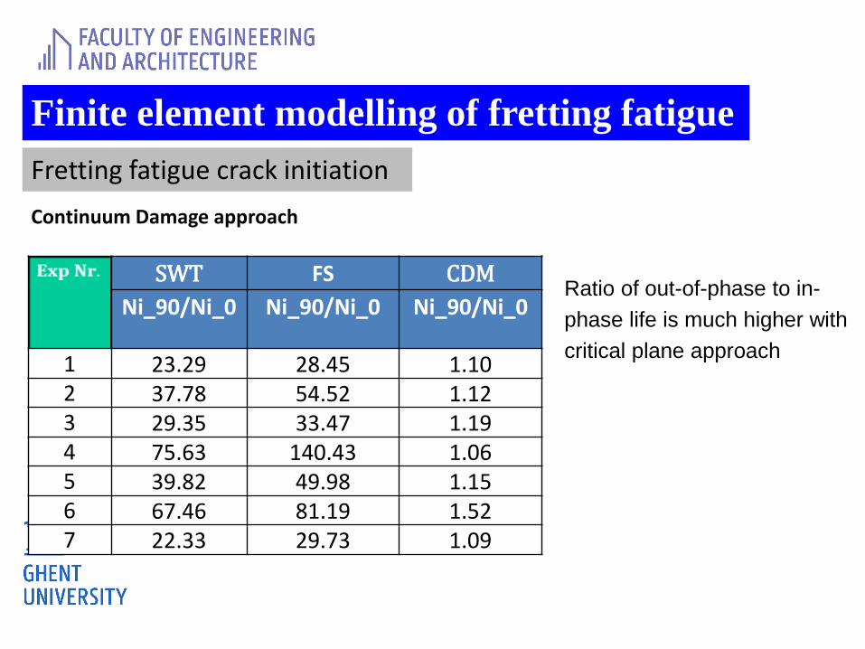
SWT FS CDM
Ni_90/Ni_0 Ni_90/Ni_0 Ni_90/Ni_0
1 23.29 28.45 1.102 37.78 54.52 1.123 29.35 33.47 1.194 75.63 140.43 1.065 39.82 49.98 1.156 67.46 81.19 1.527 22.33 29.73 1.09
Ratio of out-of-phase to in-
phase life is much higher with
critical plane approach
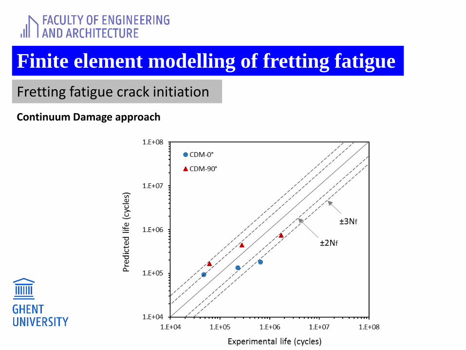
Finite element modelling of fretting fatigue
Fretting fatigue crack initiation
Continuum Damage approach
Finite element modelling of fretting fatigue
Fretting fatigue crack initiation
Continuum Damage approach
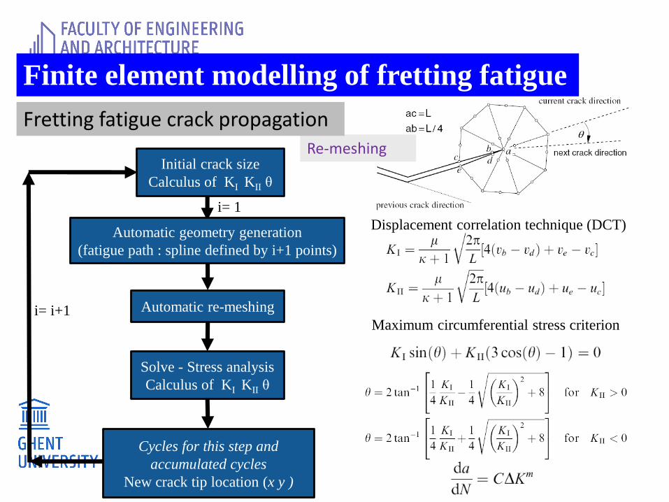
Re-meshing Initial crack size
Calculus of KI KII θ
Automatic geometry generation
(fatigue path : spline defined by i+1 points)
Automatic re-meshing
Solve - Stress analysis
Calculus of KI KII θ
Cycles for this step and
accumulated cycles
New crack tip location (x y )
i= 1
i= i+1
Displacement correlation technique (DCT)
Maximum circumferential stress criterion
Finite element modelling of fretting fatigue
Fretting fatigue crack propagation
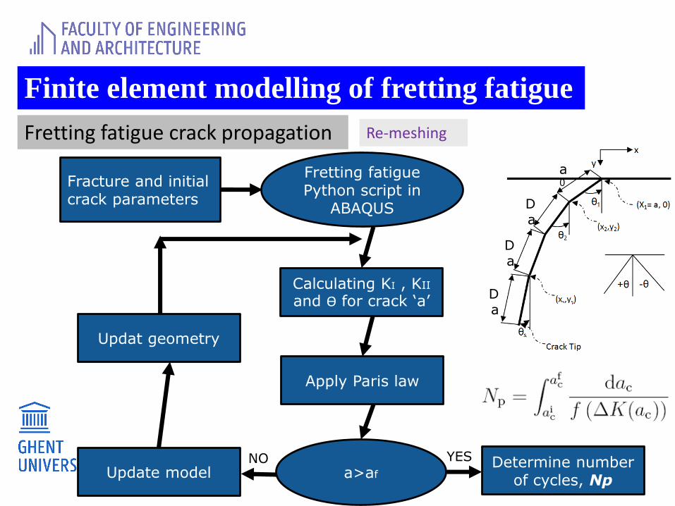
Fracture and initial crack parameters
Fretting fatigue Python script in
ABAQUS
Apply Paris law
a>afDetermine number
of cycles, Np
YES
Update model
Updat geometry
Calculating KI , KII
and ϴ for crack ‘a’
NO
a0
Da
Da
Da
Re-meshing
Finite element modelling of fretting fatigue
Fretting fatigue crack propagation
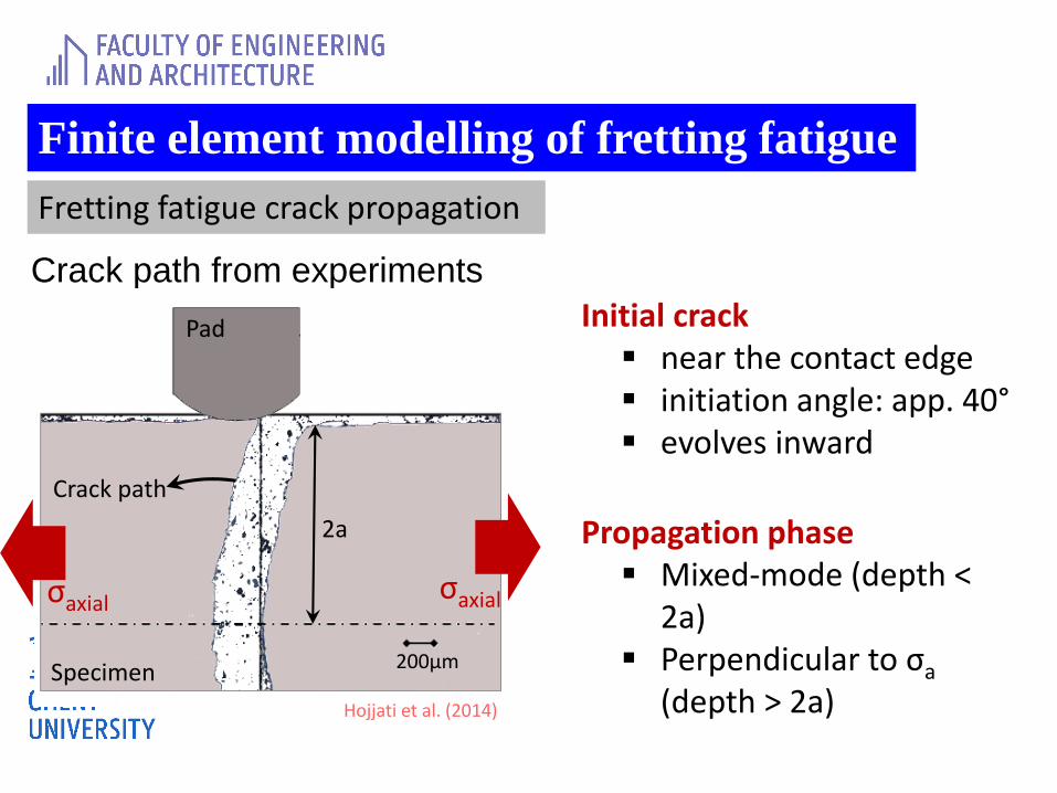
Initial crack▪ near the contact edge▪ initiation angle: app. 40°▪ evolves inward
Propagation phase▪ Mixed-mode (depth <
2a)▪ Perpendicular to σa
(depth > 2a)
Crack path from experiments
200μm
2a
Specimen
Pad
Crack path
σaxialσaxial
Hojjati et al. (2014)
Finite element modelling of fretting fatigue
Fretting fatigue crack propagation
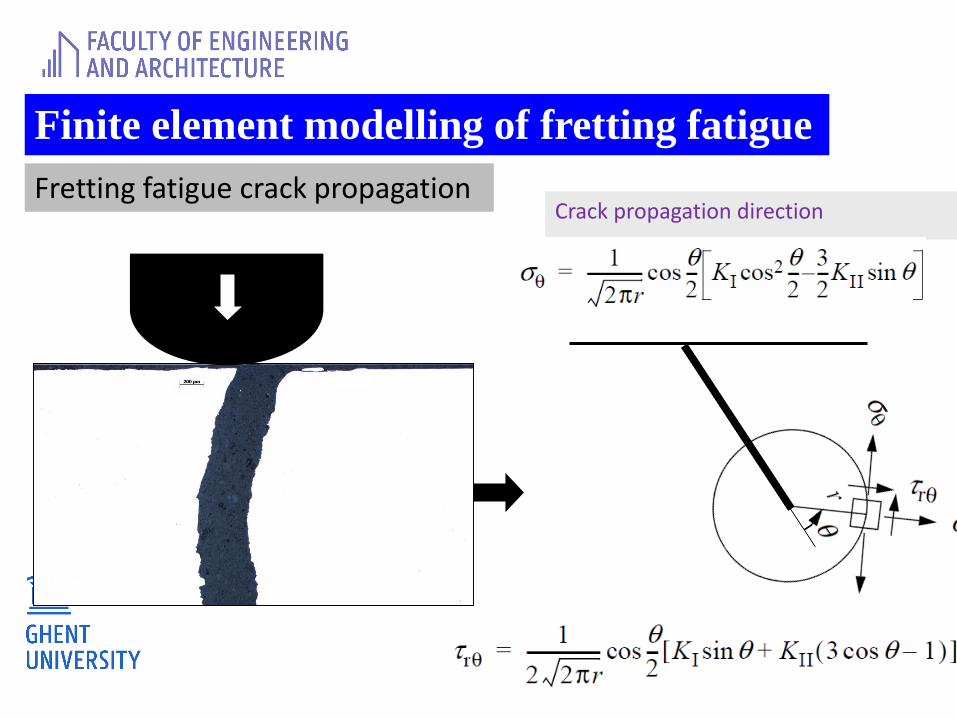
Crack propagation direction
Finite element modelling of fretting fatigue
Fretting fatigue crack propagation
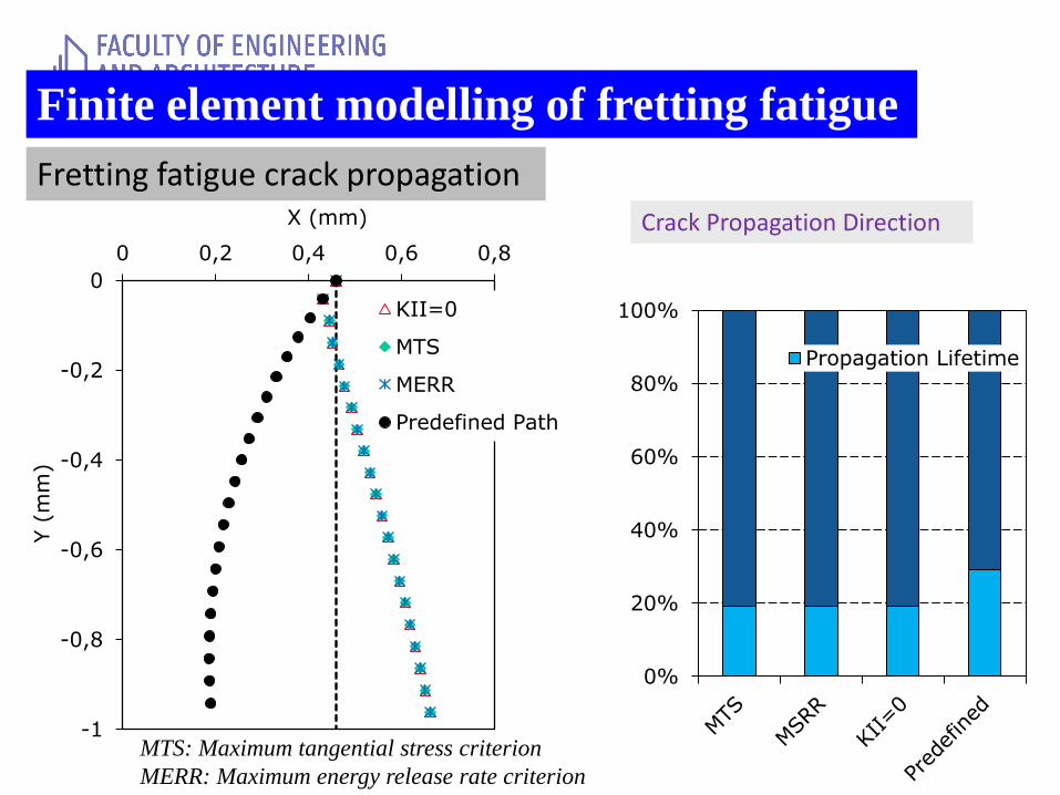
Crack Propagation Direction
0%
20%
40%
60%
80%
100%
Propagation Lifetime
-1
-0,8
-0,6
-0,4
-0,2
0
0 0,2 0,4 0,6 0,8
Y (
mm
)
X (mm)
KII=0
MTS
MERR
Predefined Path
MTS: Maximum tangential stress criterion
MERR: Maximum energy release rate criterion
Finite element modelling of fretting fatigue
Fretting fatigue crack propagation
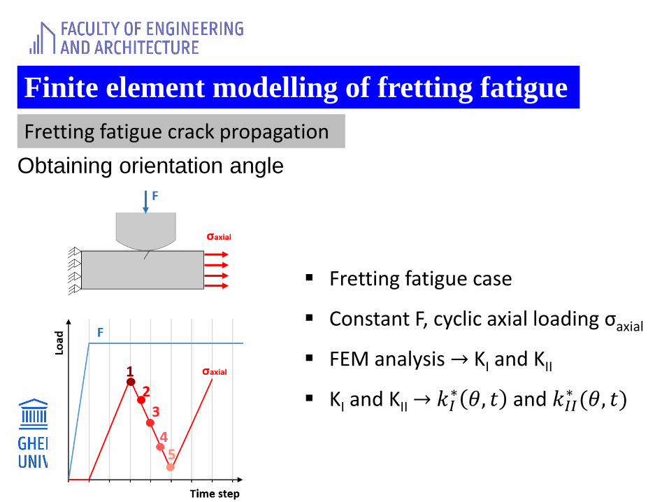
Obtaining orientation angle
▪ Fretting fatigue case
▪ Constant F, cyclic axial loading σaxial
▪ FEM analysis → KI and KII
▪ KI and KII → 𝑘𝐼∗ 𝜃, 𝑡 and 𝑘𝐼𝐼
∗ (𝜃, 𝑡)
Finite element modelling of fretting fatigue
Fretting fatigue crack propagation
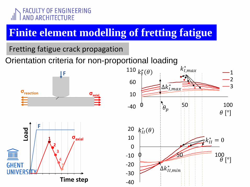
Orientation criteria for non-proportional loading
0
20
40
60
80
100
120
140
160
0 1 2 3 4 5 6 7 8
Load
Time step
F
σaxial
F
σreaction σaxial
1
2
3
45
-40
10
60
110
0 50 100
123
-40
-30
-20
-10
0
10
20
0 50 100
𝑘𝐼𝐼∗ (𝜃)
𝑘𝐼∗(𝜃)
𝜃 [°]
𝜃 [°]
∆𝑘𝐼,𝑚𝑎𝑥∗
∆𝑘𝐼𝐼,𝑚𝑖𝑛∗
𝑘𝐼,𝑚𝑎𝑥∗
𝑘𝐼𝐼∗ = 0
𝜃𝑝
Finite element modelling of fretting fatigue
Fretting fatigue crack propagation
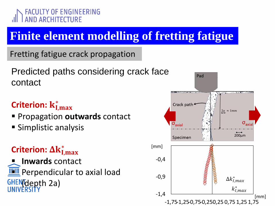
Predicted paths considering crack face
contact
-1,4
-0,9
-0,4
-1,75-1,25-0,75-0,250,25 0,75 1,25 1,75
∆𝑘_(𝐼,
[mm]
[mm]
2𝑎 ≈ 1𝑚𝑚
∆𝑘𝐼,𝑚𝑎𝑥∗
𝑘𝐼,𝑚𝑎𝑥∗
Criterion: 𝐤𝐈,𝐦𝐚𝐱∗
▪ Propagation outwards contact ▪ Simplistic analysis
Criterion: 𝚫𝐤𝐈,𝐦𝐚𝐱∗
▪ Inwards contact ▪ Perpendicular to axial load
(depth 2a)
Finite element modelling of fretting fatigue
Fretting fatigue crack propagation
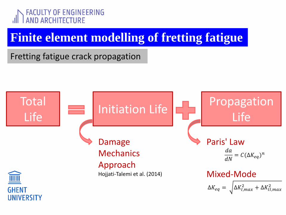
Total Life
Propagation Life
Initiation Life
DamageMechanicsApproachHojjati-Talemi et al. (2014)
Paris' Law𝑑𝑎
𝑑𝑁= 𝐶(Δ𝐾𝑒𝑞)
𝑛
Mixed-Mode
Δ𝐾𝑒𝑞 = Δ𝐾𝐼,𝑚𝑎𝑥2 + Δ𝐾𝐼𝐼,𝑚𝑎𝑥
2
Finite element modelling of fretting fatigue
Fretting fatigue crack propagation
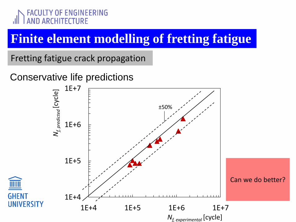
1E+4
1E+5
1E+6
1E+7
1E+4 1E+5 1E+6 1E+7
±50%
Nf,
pre
dic
ted
[cyc
le]
Nf, experimental [cycle]
Conservative life predictions
Can we do better?
Finite element modelling of fretting fatigue
Fretting fatigue crack propagation
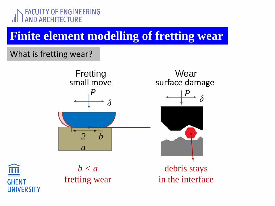
Finite element modelling of fretting wear
What is fretting wear?
Wear
2
a
PP
δ
b
b < a
fretting wear
Frettingsmall move surface damage
debris stays
in the interface
δP
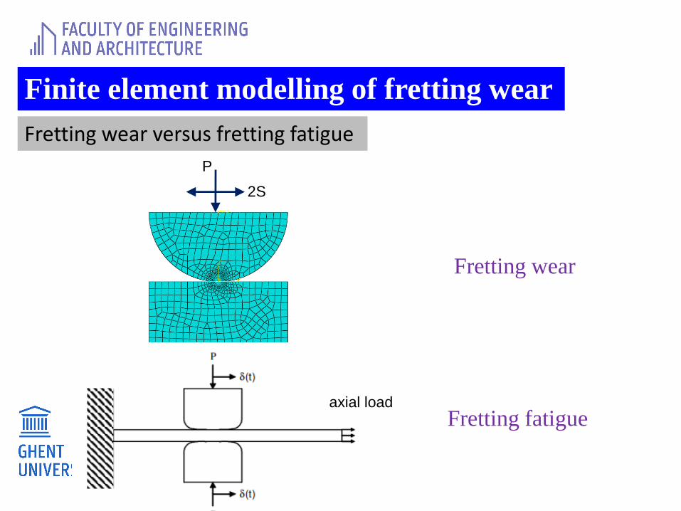
Finite element modelling of fretting wear
Fretting wear versus fretting fatigue
Fretting fatigue
P
2S
axial load
Fretting wear

Finite element modelling of fretting wear
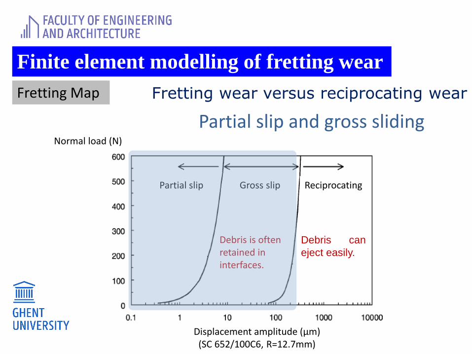
Fretting Map
Partial slip and gross sliding
Debris is often retained in interfaces.
Partial slip Gross slip Reciprocating
Debris can
eject easily.
Displacement amplitude (µm)(SC 652/100C6, R=12.7mm)
Q
Q
Q
Q
Q
Normal load (N)
Fretting wear versus reciprocating wear
Finite element modelling of fretting wear
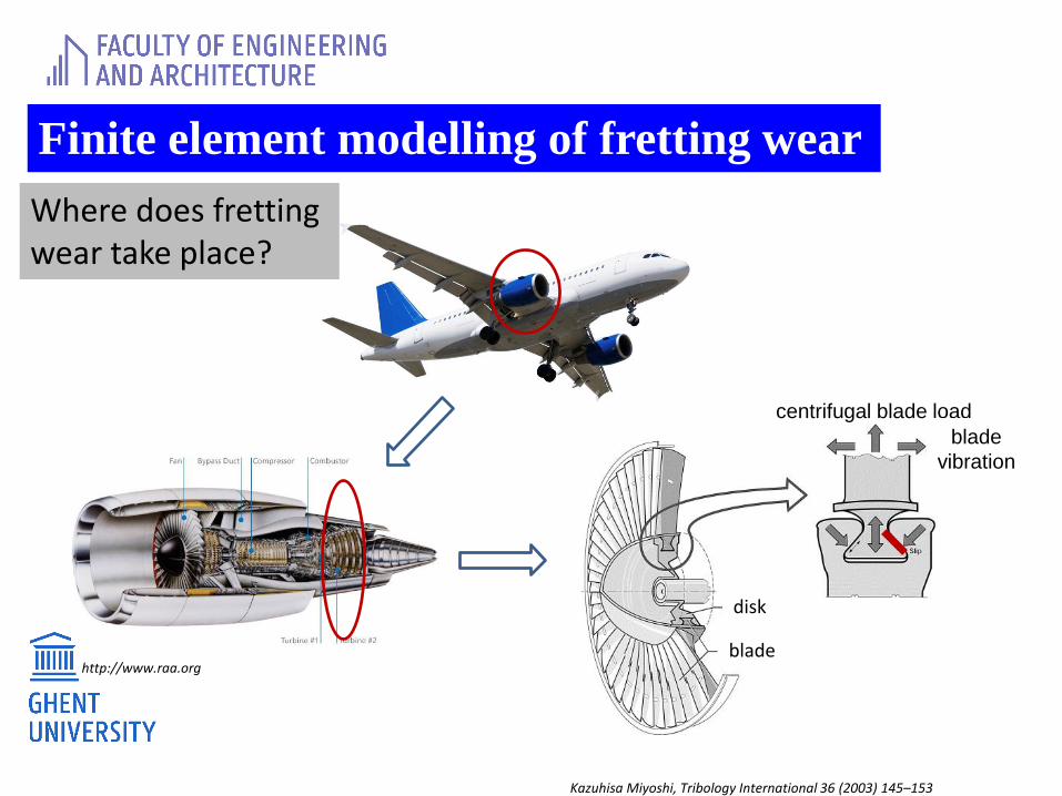
Where does fretting wear take place?
centrifugal blade load
disk
blade
blade
vibration
Kazuhisa Miyoshi, Tribology International 36 (2003) 145–153
http://www.raa.org
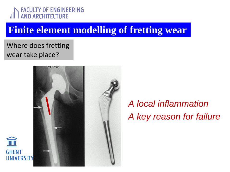
Finite element modelling of fretting wear
Where does fretting wear take place?
A local inflammation
A key reason for failure
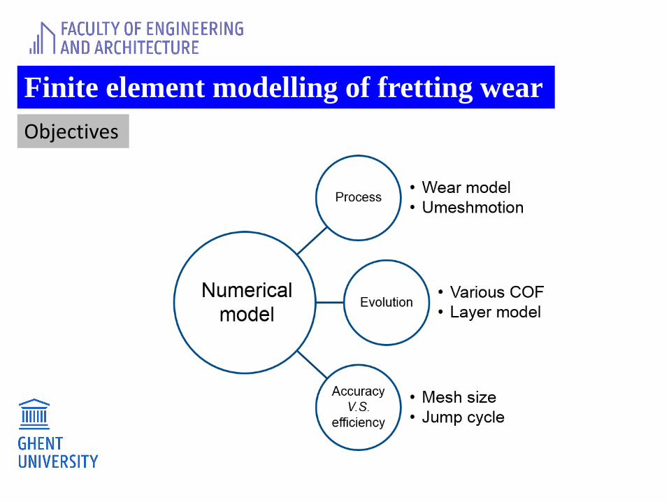
Finite element modelling of fretting wear
Objectives
Finite element modelling of fretting wear
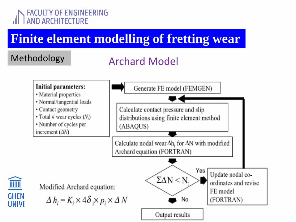
Methodology Archard Model
Finite element modelling of fretting wear
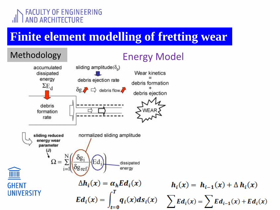
Methodology Energy Model
Finite element modelling of fretting wear
Methodology
Energy Model
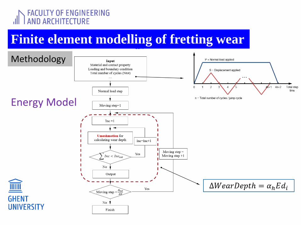
Finite element modelling of fretting wear
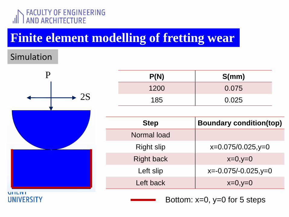
Simulation
P
2S
P(N) S(mm)
1200 0.075
185 0.025
Step Boundary condition(top)
Normal load
Right slip x=0.075/0.025,y=0
Right back x=0,y=0
Left slip x=-0.075/-0.025,y=0
Left back x=0,y=0
Bottom: x=0, y=0 for 5 steps
Finite element modelling of fretting wear
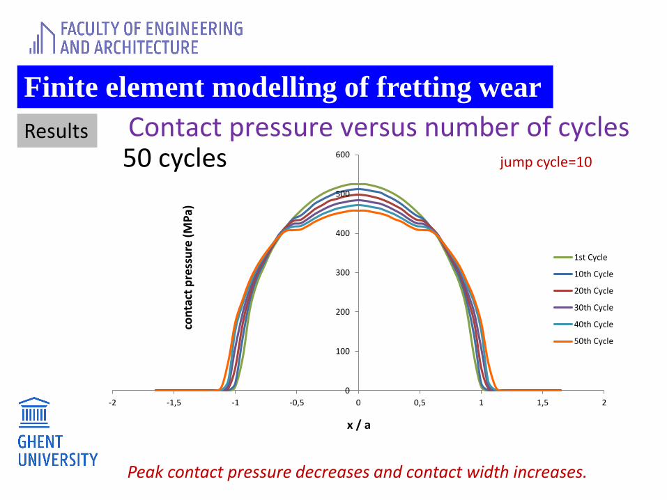
Results
50 cycles jump cycle=10
0
100
200
300
400
500
600
-2 -1,5 -1 -0,5 0 0,5 1 1,5 2
con
tact
pre
ssu
re (
MP
a)
x / a
1st Cycle
10th Cycle
20th Cycle
30th Cycle
40th Cycle
50th Cycle
Peak contact pressure decreases and contact width increases.
Contact pressure versus number of cycles
Finite element modelling of fretting wear
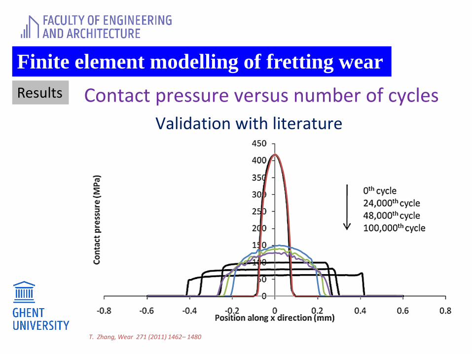
Results
T. Zhang, Wear 271 (2011) 1462– 1480
Contact pressure versus number of cycles
Validation with literature
Finite element modelling of fretting wear
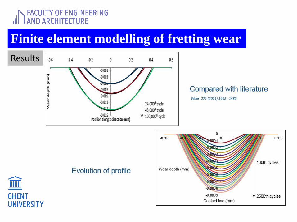
Results
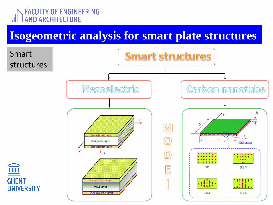
Isogeometric analysis for smart plate structures
Smart structures
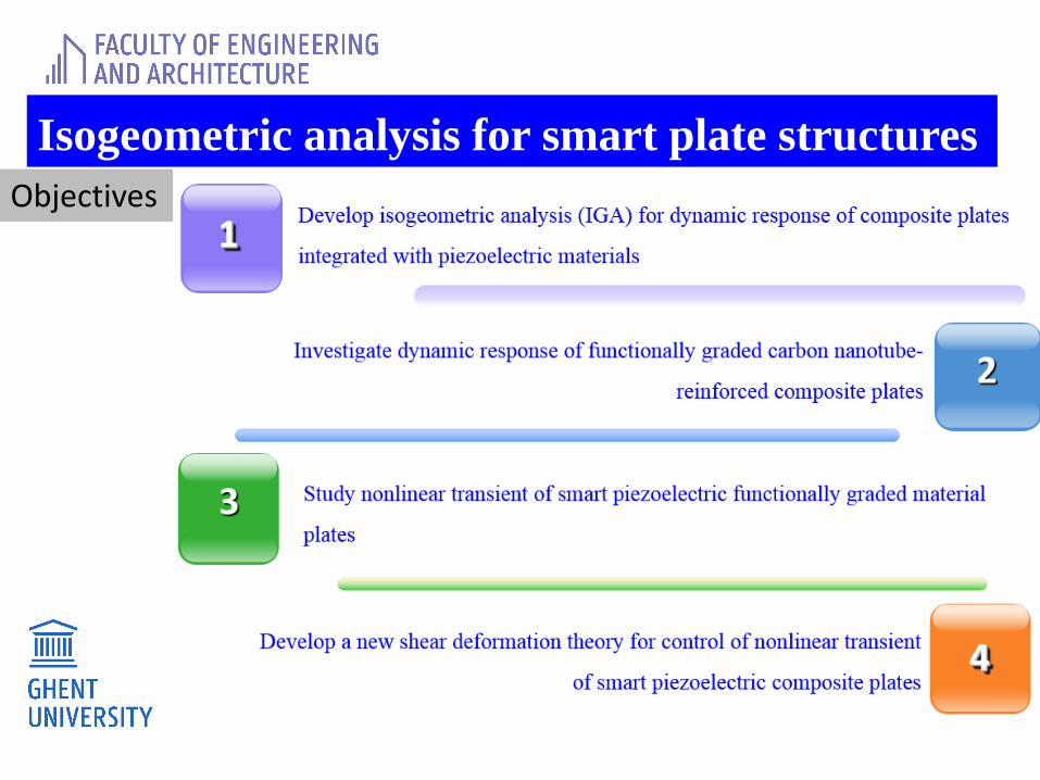
Isogeometric analysis for smart plate structures
Objectives
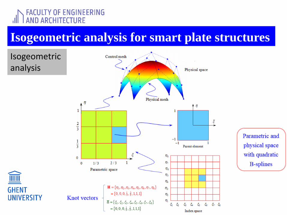
Isogeometric analysis for smart plate structures
Isogeometricanalysis
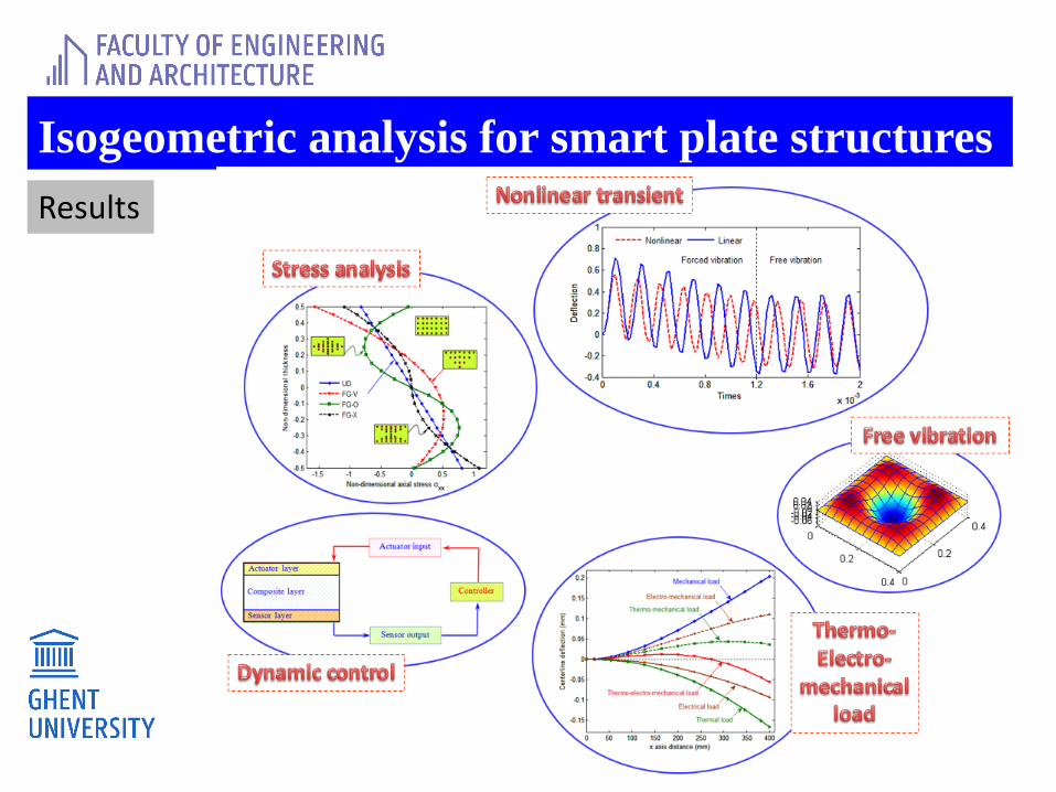
Isogeometric analysis for smart plate structures
Results
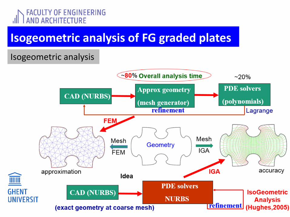
Isogeometric analysis of FG graded plates
Isogeometric analysis
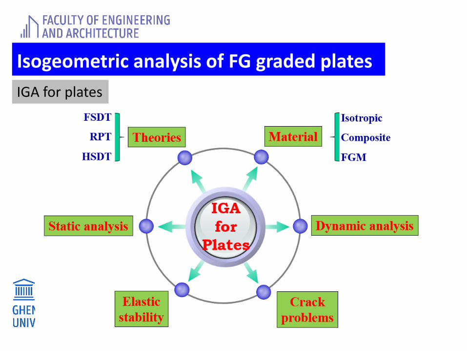
Isogeometric analysis of FG graded plates
IGA for plates
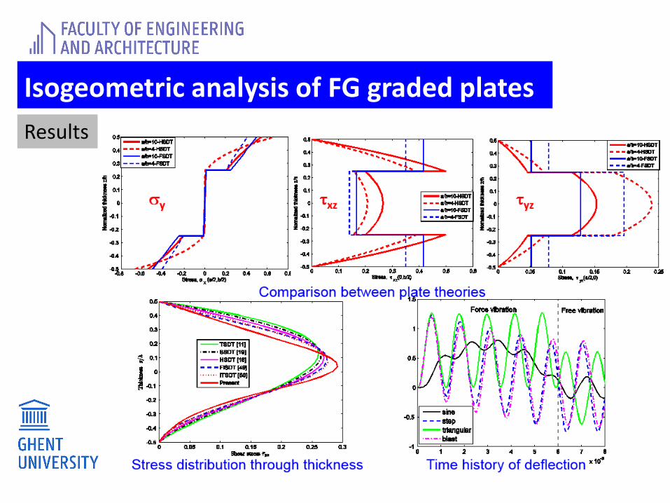
Isogeometric analysis of FG graded plates
Results
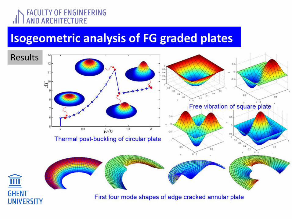
Isogeometric analysis of FG graded plates
Results
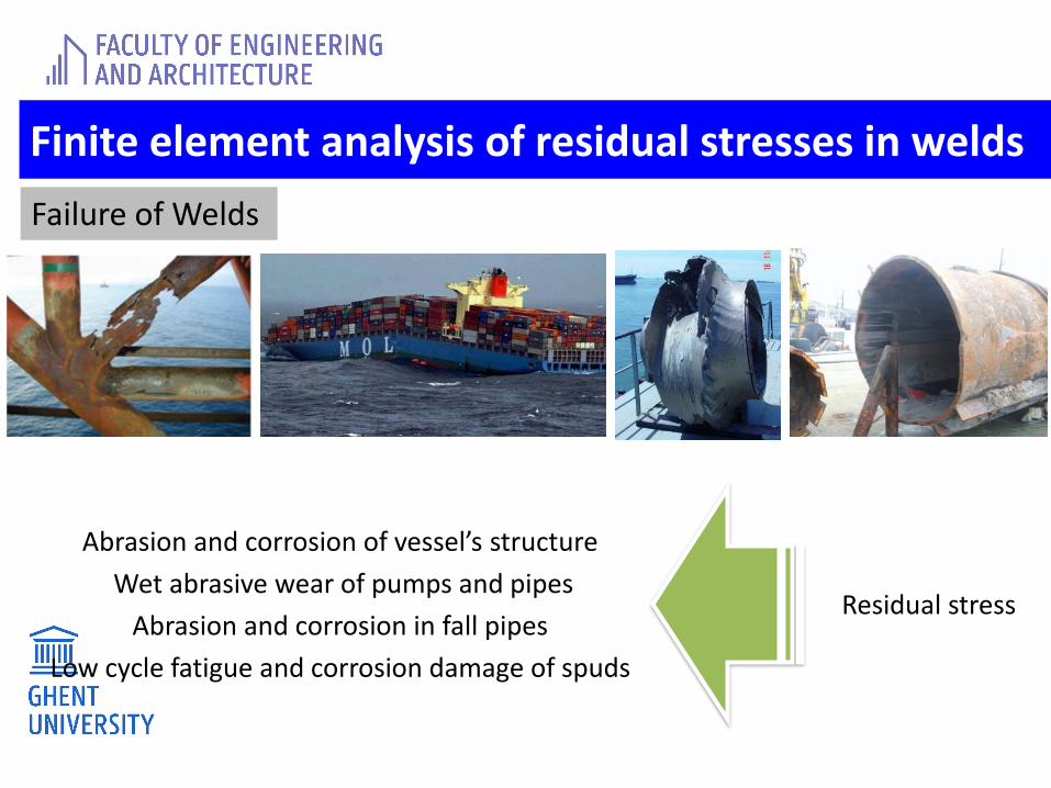
Finite element analysis of residual stresses in welds
Failure of Welds
Abrasion and corrosion of vessel’s structure
Wet abrasive wear of pumps and pipes
Abrasion and corrosion in fall pipes
Low cycle fatigue and corrosion damage of spuds
Residual stress
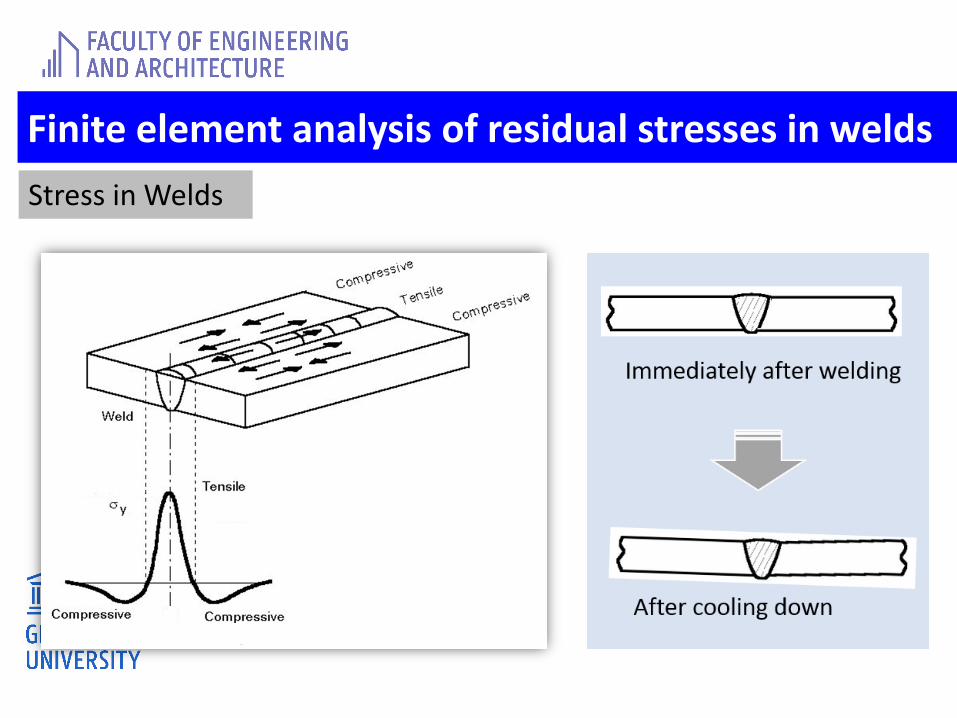
Finite element analysis of residual stresses in welds
Stress in Welds
Finite element analysis of residual stresses in welds
FEA of Welds
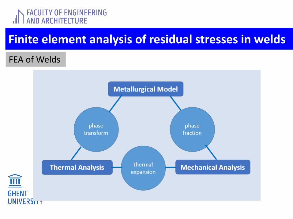
Finite element analysis of residual stresses in welds
FEA of Welds
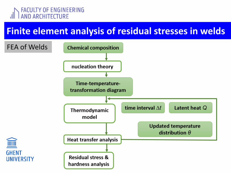
Finite element analysis of residual stresses in welds
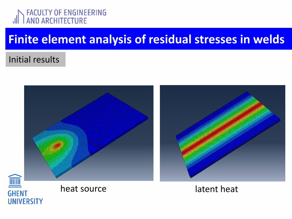
Initial results
heat source latent heat


![Finite [Mayjune2013]](https://img.pdfslide.tips/doc/110x75/55cf8d2c5503462b1392af25/finite-mayjune2013.jpg)