Embed Size (px)
Citation preview
FIRESAFE &LETHAL SERVICEBALL VALVECATALOGUE//
®
© Fort Vale Engineering Ltd. 2014
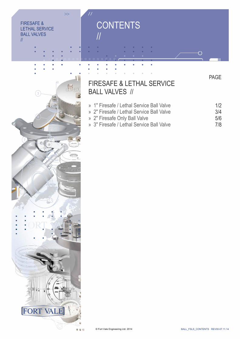
CONTENTS//
FIRESAFE & LETHAL SERVICEBALL VALVES//
FIRESAFE & LETHAL SERVICEBALL VALVES //
» 1" Firesafe / Lethal Service Ball Valve» 2" » 2" »
Firesafe / Lethal Service Ball ValveFiresafe Only Ball Valve
3" Firesafe / Lethal Service Ball Valve
© Fort Vale Engineering Ltd. 2014 BALL_FSLS_CONTENTS REV00-07.11.14
PAGE
1/23/45/67/8
®
BALL029 REV00-05.11.14
RangeSpecification
© Fort Vale Engineering Ltd. 2014
Data1" Firesafe / Lethal Service
Ball Valve
®
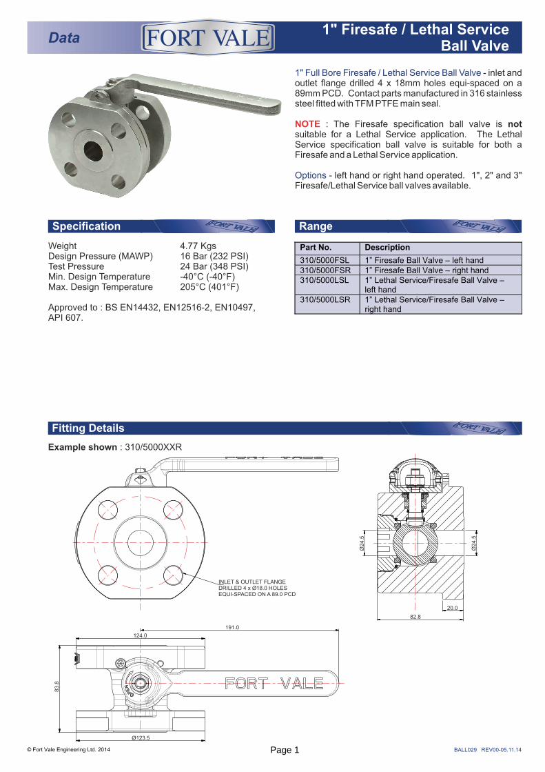
1" Full Bore Firesafe / Lethal Service Ball Valve
Options
- inlet and outlet flange drilled 4 x 18mm holes equi-spaced on a 89mm PCD. Contact parts manufactured in 316 stainless steel fitted with TFM PTFE main seal.
: The Firesafe specification ball valve is not suitable for a Lethal Service application. The Lethal Service specification ball valve is suitable for both a Firesafe and a Lethal Service application.
- left hand or right hand operated. 1", 2" and 3" Firesafe/Lethal Service ball valves available.
NOTE
Weight 4.77 KgsDesign Pressure (MAWP) 16 Bar (232 PSI)Test Pressure 24 Bar (348 PSI)Min. Design Temperature -40°C (-40°F)Max. Design Temperature 205°C (401°F)
Approved to : BS EN14432, EN12516-2, EN10497, API 607.
Part No. Description
310/5000FSL 1” Firesafe Ball Valve – left hand 310/5000FSR 1” Firesafe Ball Valve – right hand 310/5000LSL 1” Lethal Service/Firesafe Ball Valve –
left hand 310/5000LSR 1” Lethal Service/Firesafe Ball Valve –
right hand
Fitting Details
Example shown : 310/5000XXR
INLET & OUTLET FLANGE DRILLED 4 x Ø18.0 HOLES EQUI-SPACED ON A 89.0 PCD
82.8
20.0
Ø24.5
Ø24.5
Ø123.5
124.0
191.0
83.8
Page 1
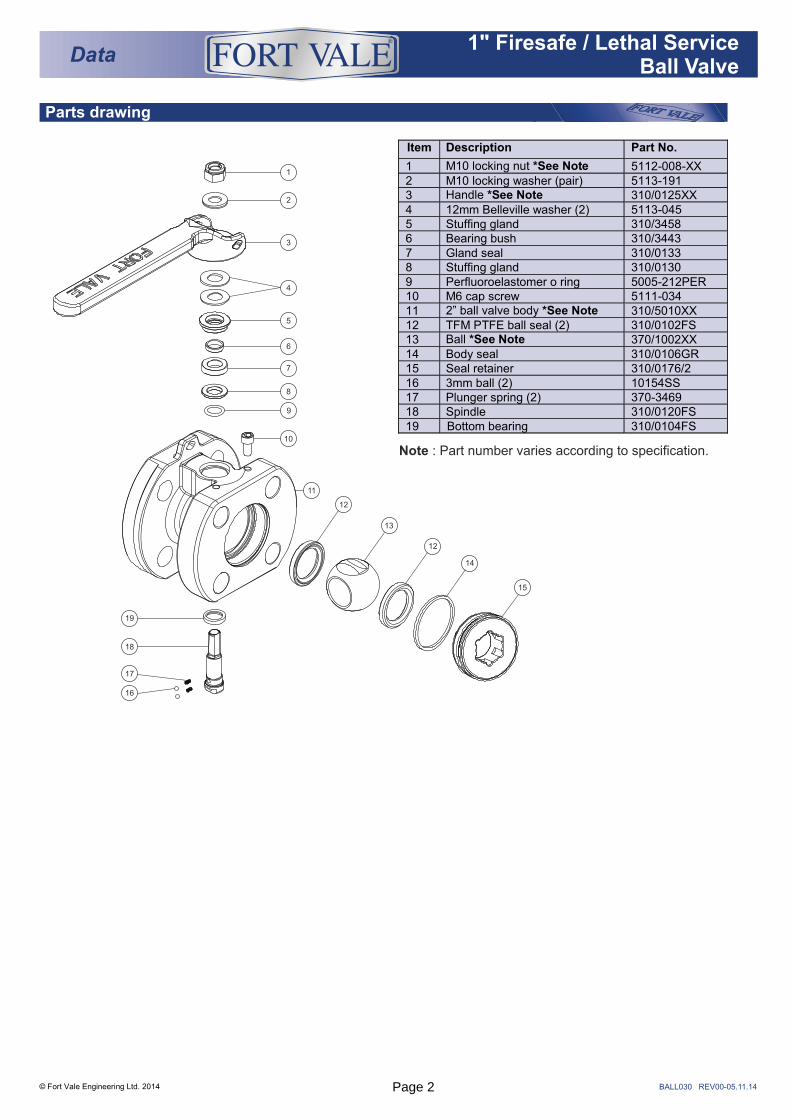
Parts drawing
© Fort Vale Engineering Ltd. 2014
Data1" Firesafe / Lethal Service
Ball Valve
®
BALL030 REV00-05.11.14
Note : Part number varies according to specification.
Item Description Part No.
1 M10 locking nut *See Note 5112-008-XX 2 M10 locking washer (pair) 5113-191 3 Handle *See Note 310/0125XX 4 12mm Belleville washer (2) 5113-045 5 Stuffing gland 310/3458 6 Bearing bush 310/3443 7 Gland seal 310/0133 8 Stuffing gland 310/0130 9 Perfluoroelastomer o ring 5005-212PER 10 M6 cap screw 5111-034 11 2” ball valve body *See Note 310/5010XX 12 TFM PTFE ball seal (2) 310/0102FS 13 Ball *See Note 370/1002XX 14 Body seal 310/0106GR 15 Seal retainer 310/0176/2 16 3mm ball (2) 10154SS 17 Plunger spring (2) 370-3469 18 Spindle 310/0120FS 19 Bottom bearing 310/0104FS
1
2
3
4
5
6
7
8
9
10
11
12
12
13
14
15
16
17
18
19
Page 2
BALL033 REV00-06.11.14
Associated Parts
RangeSpecification
© Fort Vale Engineering Ltd. 2014
Data2" Firesafe / Lethal Service
Ball Valve
®
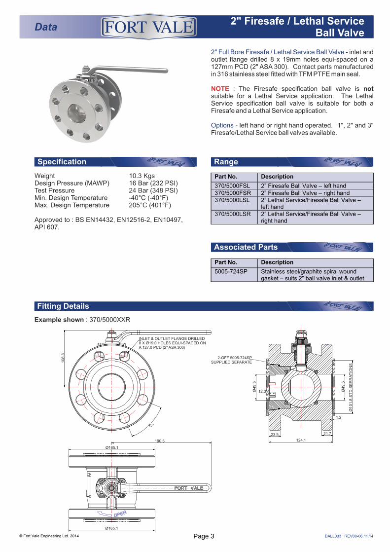
2" Full Bore Firesafe / Lethal Service Ball Valve
Options
- inlet and outlet flange drilled 8 x 19mm holes equi-spaced on a 127mm PCD (2" ASA 300). Contact parts manufactured in 316 stainless steel fitted with TFM PTFE main seal.
: The Firesafe specification ball valve is not suitable for a Lethal Service application. The Lethal Service specification ball valve is suitable for both a Firesafe and a Lethal Service application.
- left hand or right hand operated. 1", 2" and 3" Firesafe/Lethal Service ball valves available.
NOTE
Weight 10.3 KgsDesign Pressure (MAWP) 16 Bar (232 PSI)Test Pressure 24 Bar (348 PSI)Min. Design Temperature -40°C (-40°F)Max. Design Temperature 205°C (401°F)
Approved to : BS EN14432, EN12516-2, EN10497, API 607.
Part No. Description
370/5000FSL 2” Firesafe Ball Valve – left hand 370/5000FSR 2” Firesafe Ball Valve – right hand 370/5000LSL 2” Lethal Service/Firesafe Ball Valve –
left hand 370/5000LSR 2” Lethal Service/Firesafe Ball Valve –
right hand
Part No. Description
5005-724SP Stainless steel/graphite spiral wound gasket – suits 2” ball valve inlet & outlet
Fitting Details
Example shown : 370/5000XXR
INLET & OUTLET FLANGE DRILLED 8 X Ø19.0 HOLES EQUI-SPACED ON A 127.0 PCD (2" ASA 300)
108.8
45°
190.5
Ø165.1
Ø165.1
2-OFF 5005-724SPSUPPLIED SEPARATE
Ø49.5
Ø49.5
23.5
1.2
21.7
Ø101.8
ST
D S
ER
RA
TIO
NS
124.1
12.0
Page 3
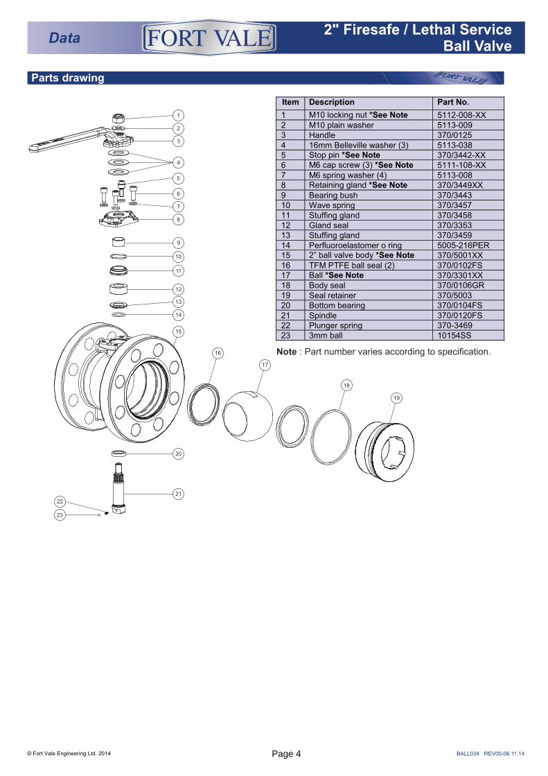
Parts drawing
© Fort Vale Engineering Ltd. 2014
Data2" Firesafe / Lethal Service
Ball Valve
®
Item Description Part No.
1 M10 locking nut *See Note 5112-008-XX 2 M10 plain washer 5113-009 3 Handle 370/0125 4 16mm Belleville washer (3) 5113-038 5 Stop pin *See Note 370/3442-XX 6 M6 cap screw (3) *See Note 5111-108-XX 7 M6 spring washer (4) 5113-008 8 Retaining gland *See Note 370/3449XX 9 Bearing bush 370/3443 10 Wave spring 370/3457 11 Stuffing gland 370/3458 12 Gland seal 370/3353 13 Stuffing gland 370/3459 14 Perfluoroelastomer o ring 5005-216PER 15 2” ball valve body *See Note 370/5001XX 16 TFM PTFE ball seal (2) 370/0102FS 17 Ball *See Note 370/3301XX 18 Body seal 370/0106GR 19 Seal retainer 370/5003 20 Bottom bearing 370/0104FS 21 Spindle 370/0120FS 22 Plunger spring 370-3469 23 3mm ball 10154SS
BALL034 REV00-06.11.14
Note : Part number varies according to specification.
1
2
3
4
5
6
7
8
9
10
11
12
21
22
23
13
14
20
15
16
17
18
19
Page 4
BALL031 REV01-05.11.14
RangeSpecification
© Fort Vale Engineering Ltd. 2014
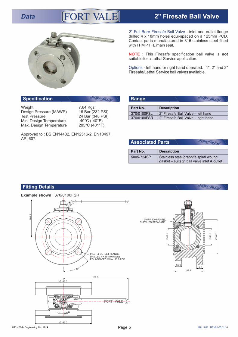
Data 2" Firesafe Ball Valve®
2" Full Bore Firesafe Ball Valve
Options
- inlet and outlet flange drilled 4 x 18mm holes equi-spaced on a 125mm PCD. Contact parts manufactured in 316 stainless steel fitted with TFM PTFE main seal.
: This Firesafe specification ball valve is not suitable for a Lethal Service application.
- left hand or right hand operated. 1", 2" and 3" Firesafe/Lethal Service ball valves available.
NOTE
Weight 7.64 KgsDesign Pressure (MAWP) 16 Bar (232 PSI)Test Pressure 24 Bar (348 PSI)Min. Design Temperature -40°C (-40°F)Max. Design Temperature 205°C (401°F)
Approved to : BS EN14432, EN12516-2, EN10497, API 607.
Fitting Details
Example shown : 370/0100FSR
Part No. Description
370/0100FSL 2” Firesafe Ball Valve – left hand 370/0100FSR 2” Firesafe Ball Valve – right hand
Associated Parts
Part No. Description
5005-724SP Stainless steel/graphite spiral wound gasket – suits 2” ball valve inlet & outlet
108.8
INLET & OUTLET FLANGE DRILLED 4 X Ø18.0 HOLES EQUI-SPACED ON A 125.0 PCD
45°
Ø165.0
Ø165.0
190.5
2-OFF 5005-724SPSUPPLIED SEPARATE
Ø49.5
Ø49.5
82.4
20.318.0
Ø102.1
Page 5
Parts drawing
© Fort Vale Engineering Ltd. 2014 BALL032 REV00-09.04.14
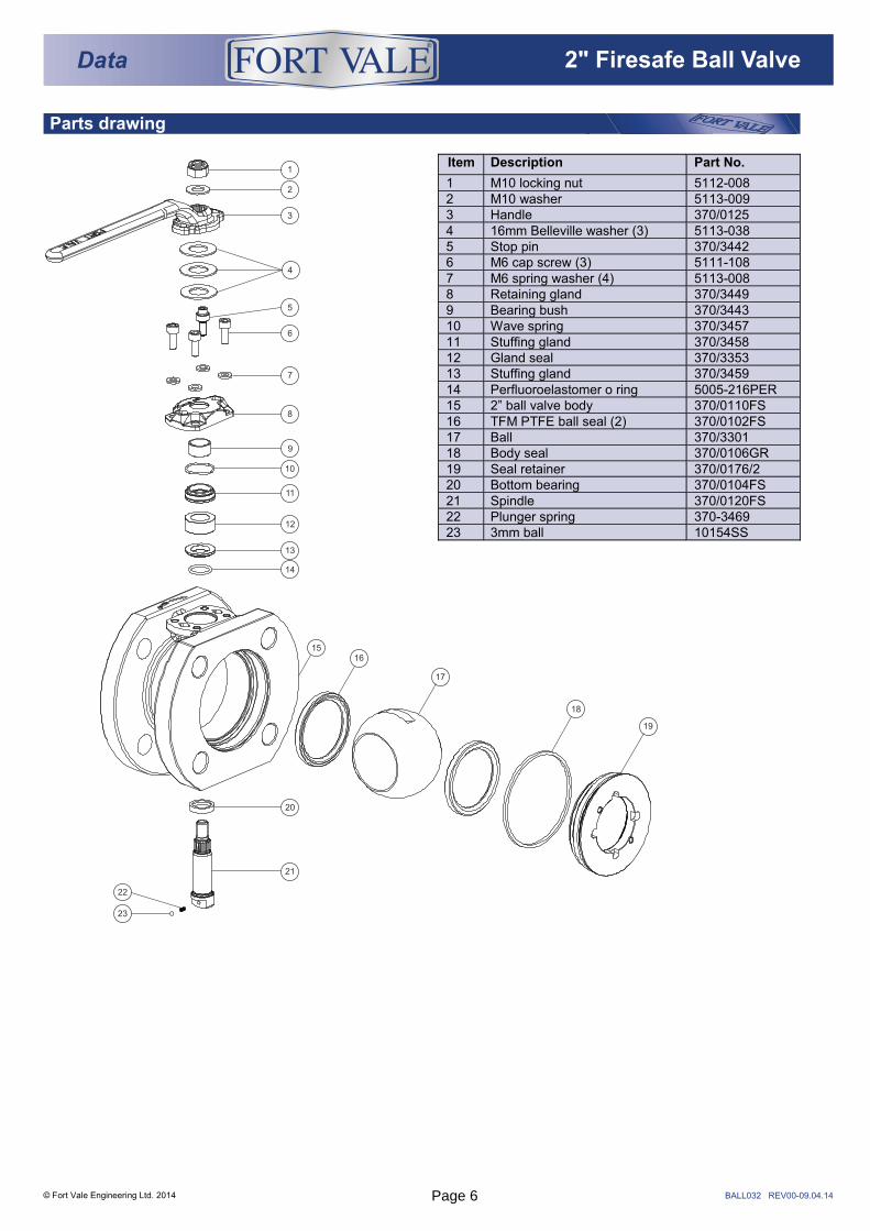
Item Description Part No.
1 M10 locking nut 5112-008 2 M10 washer 5113-009 3 Handle 370/0125 4 16mm Belleville washer (3) 5113-038 5 Stop pin 370/3442 6 M6 cap screw (3) 5111-108 7 M6 spring washer (4) 5113-008 8 Retaining gland 370/3449 9 Bearing bush 370/3443 10 Wave spring 370/3457 11 Stuffing gland 370/3458 12 Gland seal 370/3353 13 Stuffing gland 370/3459 14 Perfluoroelastomer o ring 5005-216PER 15 2” ball valve body 370/0110FS 16 TFM PTFE ball seal (2) 370/0102FS 17 Ball 370/3301 18 Body seal 370/0106GR 19 Seal retainer 370/0176/2 20 Bottom bearing 370/0104FS 21 Spindle 370/0120FS 22 Plunger spring 370-3469 23 3mm ball 10154SS
1
2
3
4
5
6
7
8
9
10
11
12
13
14
1516
17
18
19
20
21
22
23
Data 2" Firesafe Ball Valve®
Page 6
BALL035 REV00-04.11.14
Associated Parts
RangeSpecification
© Fort Vale Engineering Ltd. 2014
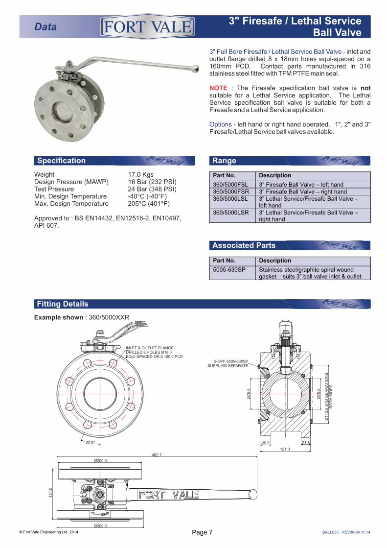
Data3" Firesafe / Lethal Service
Ball Valve
®
3" Full Bore Firesafe / Lethal Service Ball Valve
Options
- inlet and outlet flange drilled 8 x 18mm holes equi-spaced on a 160mm PCD. Contact parts manufactured in 316 stainless steel fitted with TFM PTFE main seal.
: The Firesafe specification ball valve is not suitable for a Lethal Service application. The Lethal Service specification ball valve is suitable for both a Firesafe and a Lethal Service application.
- left hand or right hand operated. 1", 2" and 3" Firesafe/Lethal Service ball valves available.
NOTE
Weight 17.0 KgsDesign Pressure (MAWP) 16 Bar (232 PSI)Test Pressure 24 Bar (348 PSI)Min. Design Temperature -40°C (-40°F)Max. Design Temperature 205°C (401°F)
Approved to : BS EN14432, EN12516-2, EN10497, API 607.
Fitting Details
Example shown : 360/5000XXR
Part No. Description
360/5000FSL 3” Firesafe Ball Valve – left hand 360/5000FSR 3” Firesafe Ball Valve – right hand 360/5000LSL 3” Lethal Service/Firesafe Ball Valve –
left hand 360/5000LSR 3” Lethal Service/Firesafe Ball Valve –
right hand
Part No. Description
5005-630SP Stainless steel/graphite spiral wound gasket – suits 3” ball valve inlet & outlet
25.7 21.8
121.0
Ø75.5
Ø75.5
Ø140.0
ST
D S
ER
RA
TIO
NS
BO
TH
SID
ES
2-OFF 5005-630SPSUPPLIED SEPARATE
INLET & OUTLET FLANGEDRILLED 8 HOLES Ø18.0 EQUI-SPACED ON A 160.0 PCD
22.5°
482.7
Ø200.0
Ø209.0
121.0
Page 7
Parts drawing
© Fort Vale Engineering Ltd. 2014
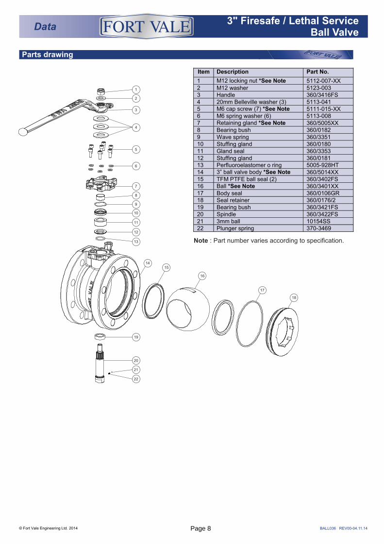
Data3" Firesafe / Lethal Service
Ball Valve
®
BALL036 REV00-04.11.14
Note : Part number varies according to specification.
Item Description Part No.
1 M12 locking nut *See Note 5112-007-XX 2 M12 washer 5123-003 3 Handle 360/3416FS 4 20mm Belleville washer (3) 5113-041 5 M6 cap screw (7) *See Note 5111-015-XX 6 M6 spring washer (6) 5113-008 7 Retaining gland *See Note 360/5005XX 8 Bearing bush 360/0182 9 Wave spring 360/3351 10 Stuffing gland 360/0180 11 Gland seal 360/3353 12 Stuffing gland 360/0181 13 Perfluoroelastomer o ring 5005-928HT 14 3” ball valve body *See Note 360/5014XX 15 TFM PTFE ball seal (2) 360/3402FS 16 Ball *See Note 360/3401XX 17 Body seal 360/0106GR 18 Seal retainer 360/0176/2 19 Bearing bush 360/3421FS 20 Spindle 360/3422FS 21 3mm ball 10154SS 22 Plunger spring 370-3469
1
2
3
4
5
6
7
8
9
10
11
12
13
1415
16
17
18
19
20
21
22
Page 8

THIS PAGE IS INTENTIONALLY BLANKPage 9
Fort Vale UKHead Office & Manufacturing PlantTel : +44 (0)1282 687120Fax : +44 (0)1282 687110Email : [email protected]
Fort Vale USATel : +1 281 471 8100Fax : +1 281 471 8116Email : [email protected]
Fort Vale NetherlandsTel : +31 (0)180 483333Fax : +31 (0)180 410797Email : [email protected]
Fort Vale Russian FederationTel : +7 916 682 0947Email : [email protected]
Fort Vale P.R. ChinaTel : +86 21 6442 1367Fax : +86 21 6442 1376Email : [email protected]
Fort Vale SingaporeTel : +65 6515 9950Fax : +65 6515 3034Email : [email protected]
Fort Vale AustraliaTel : +61 7 3310 4854Email : [email protected]
www.fortvale.com
All goods supplied will be subject to Fort Vale Engineering Ltd Terms and Conditions of Sale (Ref. FV4) which are available upon request, or may be viewed at www.fortvale.com.
Please note that this brochure and the contents herein remain the property of Fort Vale Engineering Limited.
This brochure may not be copied or reproduced, or the information contained herein divulged to any third party without the prior written permission of Fort Vale Engineering Limited.
Repair/refurbishment/resetting of Fort Vale valves may be carried out only by trained and authorised personnel. Fort Vale Engineering Limited shall not, in any circumstances, be liable for injuries, losses, expenses or damage, direct or consequential, sustained by the buyer or any person which may in any degree be attributable to the adoption, either by the buyer or any third party, of technical or other information, data or advice given on behalf of Fort Vale Engineering Limited or however otherwise caused in relation to the use of its products in accordance with Fort Vale Engineering Limited’s recommendation.
The specifications included in this catalogue are intended to be generic and must be interpreted as equivalent or functionally equivalent. The identification of many items is facilitated by illustrations (photographs and line drawings). The mention of, or reference to specific companies, national standards, or trade names, including those that might appear on the photographs, is intended for illustration purposes only. It does not imply an endorsement, preference or availability of any specific standard, brand or supplier.
The data and information contained herein is being provided for information only and without responsibility, and Fort Vale Engineering Limited makes no representations or warranties, either expressed or implied, as to the accuracy, completeness, or fitness for a particular purpose. Fort Vale Engineering Limited does not accept any responsibility or liability with regard to the reliance on, or use of this data and information.
REV10_19.03.18
®
© Fort Vale Engineering Ltd. 2018