Embed Size (px)
Citation preview
© Carl Hanser Verlag, Munchen. Der Nachdruck, auch auszugsweise, ist nicht gestattet und muss vom Verlag schriftlich genehmigt werden.
MEASURE AND TEST Coordinate Metrology1
© Carl Hanser Verlag, München QZ Qualität und Zuverlässigkeit Jahrgang 61 (2016) 10
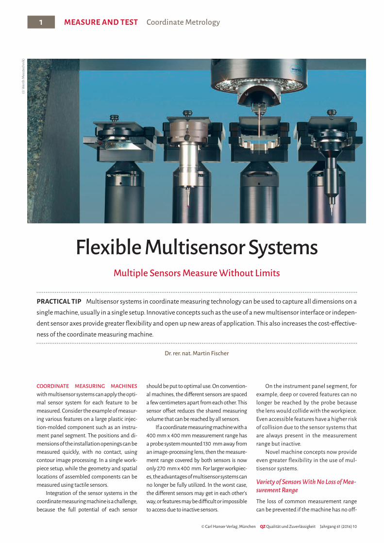
COORDINATE MEASURING MACHINES with multisensor systems can apply the opti-mal sensor system for each feature to be measured. Consider the example of measur-ing various features on a large plastic injec-tion-molded component such as an instru-ment panel segment. The positions and di-mensions of the installation openings can be measured quickly, with no contact, using contour image processing. In a single work-piece setup, while the geometry and spatial locations of assembled components can be measured using tactile sensors.
Integration of the sensor systems in the coordinate measuring machine is a challenge, because the full potential of each sensor
should be put to optimal use. On convention-al machines, the different sensors are spaced a few centimeters apart from each other. This sensor offset reduces the shared measuring volume that can be reached by all sensors.
If a coordinate measuring machine with a 400 mm x 400 mm measurement range has a probe system mounted 130 mm away from an image-processing lens, then the measure-ment range covered by both sensors is now only 270 mm x 400 mm. For larger workpiec-es, the advantages of multisensor systems can no longer be fully utilized. In the worst case, the different sensors may get in each other’s way, or features may be difficult or impossible to access due to inactive sensors.
On the instrument panel segment, for example, deep or covered features can no longer be reached by the probe because the lens would collide with the workpiece. Even accessible features have a higher risk of collision due to the sensor systems that are always present in the measurement range but inactive.
Novel machine concepts now provide even greater flexibility in the use of mul-tisensor systems.
Variety of Sensors With No Loss of Mea-surement RangeThe loss of common measurement range can be prevented if the machine has no off-
Flexible Multisensor SystemsMultiple Sensors Measure Without Limits
PRACTICAL TIP Multisensor systems in coordinate measuring technology can be used to capture all dimensions on a single machine, usually in a single setup. Innovative concepts such as the use of a new multisensor interface or indepen-dent sensor axes provide greater flexibility and open up new areas of application. This also increases the cost-effective-ness of the coordinate measuring machine.
Dr. rer. nat. Martin Fischer
(© W
erth
Mes
stec
hnik
)
© Carl Hanser Verlag, Munchen. Der Nachdruck, auch auszugsweise, ist nicht gestattet und muss vom Verlag schriftlich genehmigt werden.
Coordinate Metrology MEASURE AND TEST 2
QZ Qualität und Zuverlässigkeit Jahrgang 61 (2016) 10 www.qz-online.de
nance work and a smaller footprint, in addi-tion to the lower purchase price. Upgrades with additional sensors are also available as a plug-and-play solution.
The improved accessibility of features when using machines with several inde-pendent sensor axes also saves time when creating measurement sequences and se-ries production measurements. Perfect in-tegration of multisensor systems in the co-ordinate measuring machine thus provides a cost-effective, future-proof solution in ad-dition to maximum flexibility within the entire measurement range. W
set between the sensors – that is, all sensors are located in the same position. In Werth multisensor systems (title illustration), the various sensors are mounted in modules that are attached directly in front the beam path of the image processing sensor with a magnetic coupling.
In order to be able to measure fully au-tomatically using multiple sensors, the in-dividual sensor modules are placed in park-ing stations and loaded in the machine as needed. For measuring the instrument panel segment in the example, this means that first the features that can be captured using image processing are measured quickly without contact. For the subse-quent tactile measurements, the probe module loaded in the parking station is au-tomatically attached at the interface and all features that require tactile measurement can be measured with no offset throughout the entire measurement range.
In addition to tactile systems, the mul-tisensor system also supports the entire range of modern multisensor systems. The patented Werth Fiber Probe WFP/S is used to measure sensitive and/or very small fea-tures, a contour probe captures roughness in a standardized manner, and the laser dis-tance sensor integrated in the beam path of the image processing sensor captures con-tours without contact. Because inactive sensor modules are safely stored in their parking stations, there is practically no risk of collision.
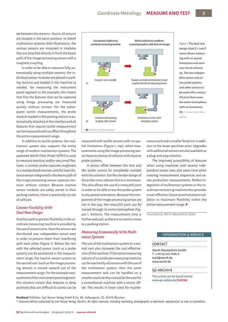
Greater Flexibility With Dual Ram DesignAnother path to greater flexibility in the co-ordinate measuring machine is provided by the use of several rams. Here the sensors are distributed over independent sensor axes in order to prevent them from interfering with each other (Figura 1). Before the ram with the selected sensor (such as a probe system) can be positioned in the measure-ment range, the inactive sensor system on the second ram (such as the image process-ing sensor) is moved upward out of the measurement range. For the example mea-surement of the instrument panel segment, this solution means that features in deep positions that are difficult to access can be
measured with tactile sensors with no spa-tial limitations (Figura 1, top), while mea-surements using the image processing sen-sor have no chance of collision with inactive probe systems.
A sensor offset between the lens and the probe cannot be completely avoided with this solution, but the slender design of the probe rams reduces this to a minimum. This also allows the use of a rotary/tilt joint in order to be able to use the probe system in any spatial orientation. Because the com-ponents of the image processing sensor are not in the way, the rotary/tilt joint can be moved through its entire hemisphere (Fig-ure 1, bottom). The measurement time is further reduced, as there is no need to move to a parking station.
Measuring Economically With Multi-sensor SystemsThe use of the multisensor system or a sec-ond ram also increases the cost-effective-ness of the machine. If the entire measuring volume of a coordinate measuring machine can be reached by all sensors with the use of the multisensor system, then the same measurement task can be handled on a smaller machine than would be the case for a conventional machine with a sensor off-set. This results in lower costs for mainte-
Figure 1. The dual ram design (dual Z = two Z rams) allows measur-ing with no spatial limitations and mini-mal risk of collision (a). The two indepen-dent sensor axes al-low probe systems and other sensors to be used with a rotary/ tilt joint that covers the entire hemisphere with no limitations (b). (© Source: Werth Mess-
technik)
© QZ Qualität und Zuverlässigkeit
CONTACTWerth Messtechnik GmbH T ++49 (0) 641 7938-0 [email protected] www.werth.de
QZ-ARCHIVEThis article can be found online: www.qz-online.de/1345182
INFORMATION & SERVICE
Masthead Publisher: Carl Hanser Verlag GmbH & Co. KG, Kolbergerstr. 22, 81679 München© Licensed edition authorised by Carl Hanser Verlag, Munich. All rights reserved, including reprinting, photographic or electronic reproduction as well as translation.
Trans la ted by Werth Messtechn ik GmbH