Embed Size (px)
Citation preview

해양플랜트공학입문
서유택

Introduction
Summary of last class
• Subsea field development
• Wet tree vs. Dry tree
• Fixed / Floating – FPSO
• Subsea production system and its operation
• Multicomponent phase diagram
• Black oil / Volatile oil / Gas condensate / Wet gas / Dry gas
Here,
We will have a look subsea tree, manifolds, and pipelines.

Field Development Plan
A Tiny Rock Sitting
On A Remote Reef
Is Now The Most
Valuable Piece Of
Real Estate In
Australia
(Business insider,
16 May 2014)

Upstream concept selection
(2012)
(2013)

Well layout
• Field development planners need to work closely with the
reservoir and drilling engineers early in the planning stages to
establish a good well location plan.
• Once the reservoir is mapped and reservoir models created, the
number of wells, types of wells, and their locations can be
optimized.
• Well layout is usually an exercise of balancing the need to
space the wells out for good recovery of the reservoir fluids
against the cost savings of grouping the wells in clusters.
• Add to this the consideration of using extended reach wells, and
the number of possible variables to consider becomes great.
• A further consideration, reservoir conditions permitting, is the
use of fewer, high production rate wells through horizontal well
completions or other well technology. Here again, there are cost
trade-off considerations.

Satellite well system
• A satellite well is an individual subsea well. Figure 2-20
illustrates a typical satellite tie-back system.
: The wells are widely separated and the production is delivered by a single
flowline from each well to a centrally located subsea manifold or production
platform.

Clustered well system
• If subsea wells can be grouped closely together, the
development cost will usually be less than that for an equivalent
number of widely dispersed wells.
• Well groupings may consist of satellite wells grouped in a
cluster, or a well template, in which the well spacing is closely
controlled by the template structure.

• Detailed design of manifold
Subsea tree
• Function requirement
: Direct the produced fluid from the well to the flowline (called
production tree) or to canalize the injection of water or gas into
the formation (called injection tree).
: Regulate the fluid flow through a choke (not always mandatory).
: Monitor well parameters at the level of the tree, such as well
pressure, annulus pressure, temperature, sand detection, etc.
:Safely stop the flow of fluid produced or injected by means of
valves actuated by a control system.
: Inject into the well or the flowline protection fluids, such as
inhibitors for corrosion or hydrate prevention.

Well head

Subsea trees

Vertical Xmass Tree
• The master valves are configured
above the tubing hanger in the
vertical Xmas tree (VXT).
• VXTs are applied commonly and
widely in subsea fields due to their
flexibility of installation and
operation.
• The production and annulus bore
pass vertically through the tree
body of the tree. Master valves and
swab valves are also stacked
vertically.
• The tubing hanger lands in the
wellhead, thus the subsea tree can
be recovered without having to
recover the downhole completion.

Main components of tree
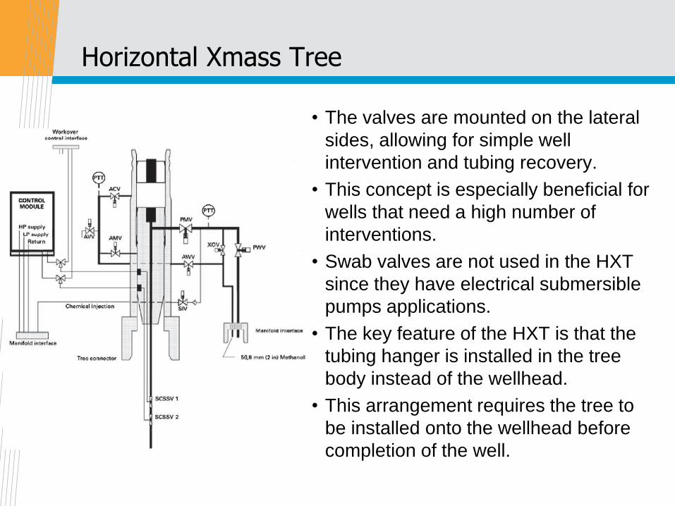
Horizontal Xmass Tree
• The valves are mounted on the lateral
sides, allowing for simple well
intervention and tubing recovery.
• This concept is especially beneficial for
wells that need a high number of
interventions.
• Swab valves are not used in the HXT
since they have electrical submersible
pumps applications.
• The key feature of the HXT is that the
tubing hanger is installed in the tree
body instead of the wellhead.
• This arrangement requires the tree to
be installed onto the wellhead before
completion of the well.


Selection criteria
• The cost of an HXT is much higher than that of a VXT; typically
the purchase price of an HXT is five to seven times more.
• A VXT is larger and heavier, which should be considered if the
installation area of the rig is limited.
• Completion of the well is another factor in selecting an HXTor
VXT. If the well is completed but the tree has not yet been
prepared, a VXT is needed. Or if an HXT is desired, then the
well must be completed after installation of the tree.
• An HXT is applied in complex reservoirs or those needing
frequent workovers that require tubing retrieval, whereas a VXT
is often chosen for simple reservoirs or when the frequency of
tubing retrieval workovers is low.
• An HXT is not recommended for use in a gas field because
interventions are rarely needed.

Design process

Flowline connector
• A flowline connector is used to connect subsea flowlines and
umbilicals via a jumper to the subsea tree. In some cases, the
flowline connector also provides the means for disconnecting
and removing the tree without retrieving the subsea flowline or
umbilical to the surface.

Tie-in to flowline

Tree valves
• Subsea Xmas tree contains various valves used for testing,
servicing, regulating, or choking the stream of produced oil,
gas, and liquids coming up from the well below
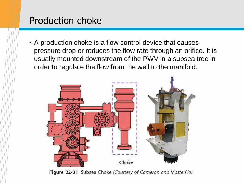
Production choke
• A production choke is a flow control device that causes
pressure drop or reduces the flow rate through an orifice. It is
usually mounted downstream of the PWV in a subsea tree in
order to regulate the flow from the well to the manifold.

• Trims / orifices types
: Typical orifices used are of the disk type or needle/plug type.
: The disk type acts by rotating one disk and having one fixed.
This will ensure the necessary choking effect.
: The needle/plug type regulates the flow by moving the insert
and thereby providing a gap with the body. The movement is
axial.

• Choke Design Parameters
: Several measurements must be known in order to select the
proper choke for a subsea production system
: how fast the flow is coming into the choke, the inlet pressure P1
of the flow, the pressure drop that occurs crossing the orifice,
and the outlet or downstream pressure P2 of the flow,
• Choke sizing is determined by coefficient value (Cv), which
takes into account all dimensions as well as other factors,
including size and direction changes, that affect fluid flow in a
choke.
• The Cv equals number of gallons of per minute that will pass
through a restriction (orifice) with a pressure drop of 1 psi at
60oC.
• This Cv calculation normally follows Instrument Society of
America (ISA) guidelines.

Pressure drop and recovery
• Pressure is maintained through the tree piping as P1. When the
flow crosses the orifice of the choke, the pressure drops. But
soon the pressure will recover to a level (P2).

• The pressure drop is determined by the equation ΔP=P1 – P2
(inlet pressure minus outlet pressure).
• The ΔP ratio, ΔPR = ΔP/P1.
• It is considered the most important parameter for evaluating
and ensuring the success of the subsea field development
project.
• It is used to measure the capacity and recovery of the choke.
The higher the value of ΔPR, the higher the potential damage to
the choke trim or body. Normally a special review of the trim is
required if DPR is beyond 0.6.

Tree cap
• Tree caps are designed to both prevent fluid from leaking from
the wellbore into the environment and small dropped objects
from getting into the mandrel.
• Tree caps are installed, locked, unlocked, released, and
recovered via ROV-assisted operations.

Subsea control module

P and T transmitter
• pressure and temperature sensors are placed in the annulus
and production bore and upstream and downstream of the
choke.

Chemical injection

Protection
• Cathodic protection is electrochemical protection that functions
by making the metal surface of an electrochemical cell into a
cathode that can decrease the corrosion potential to an
acceptable level.
• The trees and wellhead require corrosion coatings and thermal
insulation to enable sufficient cooldown time in the event of a
production stoppage.
: to have sufficient time to perform preservation sequence
: to avoid dramatic consequences of hydrate formation

Installation


해저배관제작및설치

Subsea pipelines
• Normally, the term “subsea flowlines” is used to describe the
subsea pipelines carrying oil and gas products from the
wellhead to the riser foot.

Design process
Internal diameter

Design analysis
• Wall thickness analysis
: The wall-thickness level for pipelines should be able to withstand
pressure and pressure effect (hoop and burst strength)
: A difference of internal pressure and external pressure in a pipeline
produces stresses in the wall of a pipeline. These stresses are the
longitudinal stress σL, the hoop stress σH, and the radial stress σR.

On-bottom stability analysis
• Subsea pipelines resting on the seabed are subject to fluid
loading from both waves and steady currents.
• For regions of the seabed where damage may result from
vertical or lateral movement of the pipeline, it is a design
requirement for the pipe weight to be sufficient to ensure
stability under the worst possible environmental conditions.
• In most cases this weight is provided by a concrete coating on
the pipeline. In some circumstances the pipeline may be
allowed to move laterally if provided stress limits are not
exceeded.
• The wave and current data must be based on extreme
conditions. For example, the wave with a probability of
occurring only once in 100 years is often used for the
operational lifetime of a pipeline.

• For the pipeline to be stable on the seabed, the following
relationship must be satisfied:
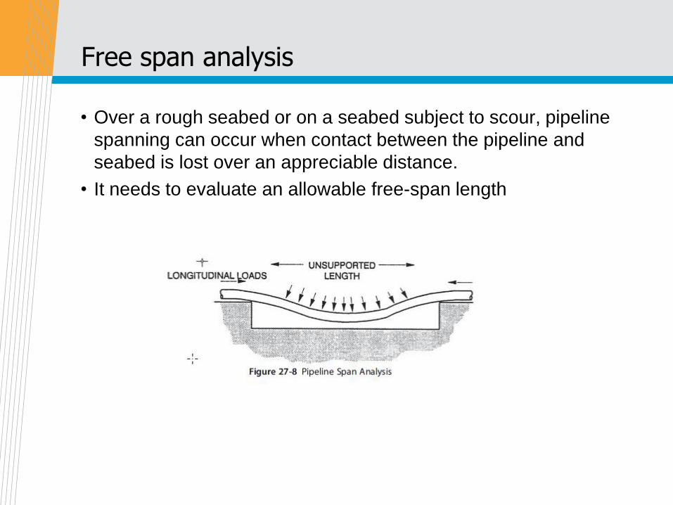
Free span analysis
• Over a rough seabed or on a seabed subject to scour, pipeline
spanning can occur when contact between the pipeline and
seabed is lost over an appreciable distance.
• It needs to evaluate an allowable free-span length

Global buckling analysis
• Global buckling of a pipeline occurs when the effective
compressible force within the line becomes so great that the
line has to deflect and, hence, reduces these axial loads.
• Analysis will be performed to identify whether the global
buckling is likely to occur

Pipeline installation
• In early days, the pipeline was fabricated at beach and towed to
the project field by a tug boat.
• Most widely used installation method is using a pipeline
installation vessel which can weld pipe joints on the deck and
lower the pipes by releasing the pipes from the tensioners while
moving the vessel.
• Depending on the pipeline’s profile from the vessel to the sea
floor, it is called S-lay or J-lay.
• Another installation method is to fabricate the pipeline at spool
base near beach and reel the pipe onto the reel ship. Then the
reel ship carry the reeled pipe to the project field and lay by un-
spooling the pipes.

• The four pipeline installation methods
(bottom tow, mid-depth
tow, and surface tow)

Pipeline installation

Production risers
• Steel catenary risers (SCRs),
• Top tensioned risers (TTRs),
• Flexible risers,
• Hybrid risers.

Steel Catenary Risers (SCRs)
• SCRs clearly have similarities with free-hanging flexible risers, being
horizontal at the lower end and generally within about 20o of the
vertical at the top end.
• The SCR is a cost-effective alternative for oil and gas export and for
water injection lines on deepwater fields, where the large-diameter
flexible risers present technical and economic limitations.
• The SCR is sensitive to waves and current due to the normally low
level of effective tension on the riser. The fatigue damage induced by
vortex-induced vibrations (VIVs) can be fatal to the riser.

Top Tensioned Risers (TTRs)
• TTRs are long circular cylinders used to link the seabed to a floating
platform.
• The risers are provided with tensioners at the top to maintain the
angles at the top and bottom under the environmental loading. The
risers often appear in a group arranged in a rectangular or circular
array.

Flexible Risers
• Flexible risers are multiple-layer composite pipes with relative bending
stiffness, to provide performance that is more compliant.
• Flexible pipes were found to be ideally suited for offshore applications
in the form of production and export risers, as well as flowlines.
• The main characteristic of a flexible pipe is its low relative bending to
axial stiffness. This characteristic is achieved through the use of a
number of layers of different materials in the pipe wall fabrication.

• The flexible pipe structure is composed of several layers (e.g.,
carcass) made of stainless steel to resist external pressure.
• The internal sheath acts as an internal fluid containment barrier,
the pressure armor is made of carbon steel to resist hoop pressure,
the tensile armor is made of carbon steel to resist tensile loading, and
the external sheath is a kind of external fluid barrier.

Hybrid riser
• The concept of a hybrid riser was developed based on the TTRs. Its
principal feature is that it accommodates relative motion between a
floating structure and a rigid metal riser, by connecting them with
flexible jumpers.
• The lines are attached to hard piping on the base, which provides a
connection to the subsea flowlines, and terminates in goosenecks
some 30 to 50 m below the water surface.

Main components

Hydraulic Power Unit (HPU)
• Provides system hydraulic pressure
• Stores control fluid energy
• Supplies clean hydraulic fluid
• Regulates supply pressure
• Sends status information to the MCS (Master Control Station)
• Allows remote or local control

Subsea Control Pod
• Subsea control center
• Executes commands from the surface
• Features
: Must be fully retrievable
: Receives and sends signals to MCS
: Tracks internal status and transmits to the MCS
: Functions subsea valves
: Monitors subsea sensors
: Re-configuration from topside
• May operate 18 – 24 hydraulic functions
• May monitor 8 – 10 remote sensor inputs

Subsea Umbilicals
• Provides link between surface (operator) and subsea
equipment
• Supplies hydraulic fluid to operate subsea valves and chokes
• Supplies electrical power to operate subsea electronics
• Transmits electronic signals to execute operational commands
subsea
• Returns electronic data to the surface from subsea
instrumentation

Subsea umbilicals
• Design Considerations:
: Water depth
: Tie-back type
: Tie-back length
: Service life
: Installation
: Chemical compatibility
: Flow rates
: Internal pressures
: Size of field

Umbilical Termination Assembly
• Umbilical Termination Assembly (UTA)
: Provides the subsea termination
for the umbilical
: Can be the subsea distribution
point for hydraulic fluid, electrical
power, electronic signals, and
injection chemicals
: Provides an interface for flying
leads or SDUs
: Can be retrieved for maintenance

Thank you!