Embed Size (px)
Citation preview
Flow Separation Control on a Full-Scale Vertical Tail Model using Sweeping Jet Actuators
Marlyn Y. Andino*, John C. Lin†, Anthony E. Washburn‡
NASA Langley Research Center, Hampton, VA, 23681, USA
Edward A. Whalen§ The Boeing Company, Hazelwood, MO, 63042, USA
Emilio C. Graff **
California Institute of Technology, Pasadena, CA 91125, USA
Israel J. Wygnanski†† The University of Arizona, Tucson, AZ, 85721, USA
* Aerospace Engineer, Flow Physics and Control Branch, MS 170, AIAA Senior Member † Aerospace Engineer, Flow Physics and Control Branch, MS 170, AIAA Associate Fellow ‡ AeroScience Lead, Flow Physics and Control Branch, MS 41 § R & D Engineer, Boeing Research & Technology, Mail Stop: S306-4030, AIAA Senior Member ** Research Project Manager, Graduate Aerospace Laboratories, AIAA Member †† Professor, Aerospace and Mechanical Engineering Department, AIAA Fellow
Abstract
This paper describes test results of a joint NASA/Boeing research effort to advance Active Flow Control (AFC) technology to enhance aerodynamic efficiency. A full-scale Boeing 757 vertical tail model equipped with sweeping jets AFC was tested at the National Full-Scale Aerodynamics Complex 40- by 80-Foot Wind Tunnel at NASA Ames Research Center. The flow separation control optimization was performed at 100 knots, a maximum rudder deflection of 30°, and sideslip angles of 0° and -7.5°. Greater than 20% increments in side force were achieved at the two sideslip angles with a 31-actuator AFC configuration. Flow physics and flow separation control associated with the AFC are presented in detail. AFC caused significant increases in suction pressure on the actuator side and associated side force enhancement. The momentum coefficient (Cμ) is shown to be a useful parameter to use for scaling-up sweeping jet AFC from sub-scale tests to full-scale applications. Reducing the number of actuators at a constant total Cμ of approximately 0.5% and tripling the actuator spacing did not significantly affect the flow separation control effectiveness.
Nomenclature
AFC = active flow control APU = auxiliary power unit c = total local chord length CFD = computational fluid dynamics Cp = pressure coefficient Cy = side force coefficient Cμ = momentum coefficient, % ERA = Environmentally Responsible Aviation LE = leading edge M∞ = free stream Mach number
NFAC = National Full-Scale Aerodynamics Complex
Re = Reynolds number based on mean aerodynamic chord
U∞ = free stream velocity, knots x = streamwise direction β = sideslip angle, degrees δRudder = flap deflection angle, degrees %ΔCy = % difference in Cy with respect to AFC
off, 100%*(Cy - Cy, AFC off)/ Cy, AFC off
https://ntrs.nasa.gov/search.jsp?R=20150006023 2018-07-18T09:32:55+00:00Z
2
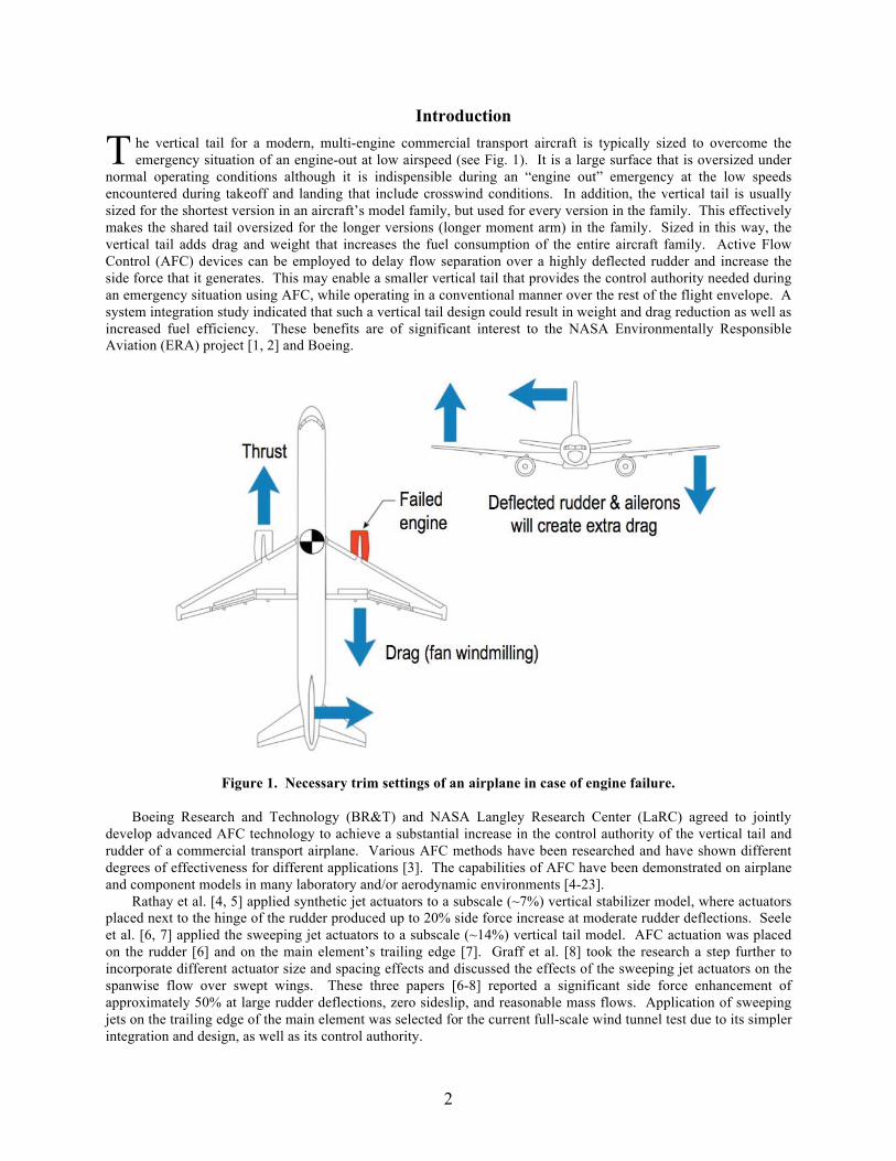
Introduction he vertical tail for a modern, multi-engine commercial transport aircraft is typically sized to overcome the emergency situation of an engine-out at low airspeed (see Fig. 1). It is a large surface that is oversized under
normal operating conditions although it is indispensible during an “engine out” emergency at the low speeds encountered during takeoff and landing that include crosswind conditions. In addition, the vertical tail is usually sized for the shortest version in an aircraft’s model family, but used for every version in the family. This effectively makes the shared tail oversized for the longer versions (longer moment arm) in the family. Sized in this way, the vertical tail adds drag and weight that increases the fuel consumption of the entire aircraft family. Active Flow Control (AFC) devices can be employed to delay flow separation over a highly deflected rudder and increase the side force that it generates. This may enable a smaller vertical tail that provides the control authority needed during an emergency situation using AFC, while operating in a conventional manner over the rest of the flight envelope. A system integration study indicated that such a vertical tail design could result in weight and drag reduction as well as increased fuel efficiency. These benefits are of significant interest to the NASA Environmentally Responsible Aviation (ERA) project [1, 2] and Boeing.
Figure 1. Necessary trim settings of an airplane in case of engine failure.
Boeing Research and Technology (BR&T) and NASA Langley Research Center (LaRC) agreed to jointly develop advanced AFC technology to achieve a substantial increase in the control authority of the vertical tail and rudder of a commercial transport airplane. Various AFC methods have been researched and have shown different degrees of effectiveness for different applications [3]. The capabilities of AFC have been demonstrated on airplane and component models in many laboratory and/or aerodynamic environments [4-23].
Rathay et al. [4, 5] applied synthetic jet actuators to a subscale (~7%) vertical stabilizer model, where actuators placed next to the hinge of the rudder produced up to 20% side force increase at moderate rudder deflections. Seele et al. [6, 7] applied the sweeping jet actuators to a subscale (~14%) vertical tail model. AFC actuation was placed on the rudder [6] and on the main element’s trailing edge [7]. Graff et al. [8] took the research a step further to incorporate different actuator size and spacing effects and discussed the effects of the sweeping jet actuators on the spanwise flow over swept wings. These three papers [6-8] reported a significant side force enhancement of approximately 50% at large rudder deflections, zero sideslip, and reasonable mass flows. Application of sweeping jets on the trailing edge of the main element was selected for the current full-scale wind tunnel test due to its simpler integration and design, as well as its control authority.
T
3
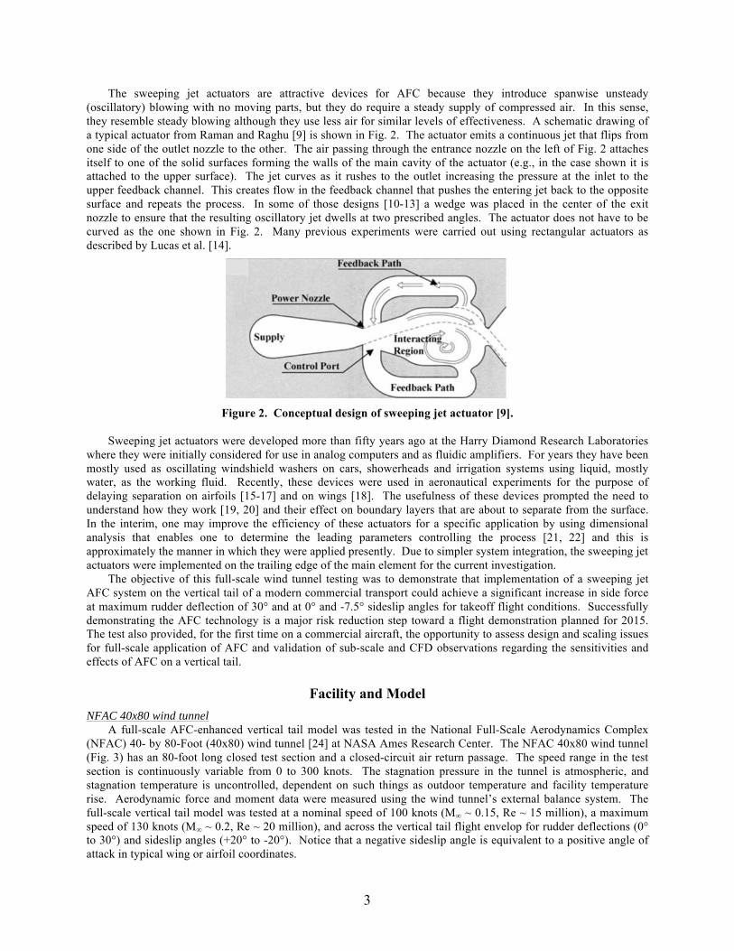
The sweeping jet actuators are attractive devices for AFC because they introduce spanwise unsteady (oscillatory) blowing with no moving parts, but they do require a steady supply of compressed air. In this sense, they resemble steady blowing although they use less air for similar levels of effectiveness. A schematic drawing of a typical actuator from Raman and Raghu [9] is shown in Fig. 2. The actuator emits a continuous jet that flips from one side of the outlet nozzle to the other. The air passing through the entrance nozzle on the left of Fig. 2 attaches itself to one of the solid surfaces forming the walls of the main cavity of the actuator (e.g., in the case shown it is attached to the upper surface). The jet curves as it rushes to the outlet increasing the pressure at the inlet to the upper feedback channel. This creates flow in the feedback channel that pushes the entering jet back to the opposite surface and repeats the process. In some of those designs [10-13] a wedge was placed in the center of the exit nozzle to ensure that the resulting oscillatory jet dwells at two prescribed angles. The actuator does not have to be curved as the one shown in Fig. 2. Many previous experiments were carried out using rectangular actuators as described by Lucas et al. [14].
Figure 2. Conceptual design of sweeping jet actuator [9].
Sweeping jet actuators were developed more than fifty years ago at the Harry Diamond Research Laboratories
where they were initially considered for use in analog computers and as fluidic amplifiers. For years they have been mostly used as oscillating windshield washers on cars, showerheads and irrigation systems using liquid, mostly water, as the working fluid. Recently, these devices were used in aeronautical experiments for the purpose of delaying separation on airfoils [15-17] and on wings [18]. The usefulness of these devices prompted the need to understand how they work [19, 20] and their effect on boundary layers that are about to separate from the surface. In the interim, one may improve the efficiency of these actuators for a specific application by using dimensional analysis that enables one to determine the leading parameters controlling the process [21, 22] and this is approximately the manner in which they were applied presently. Due to simpler system integration, the sweeping jet actuators were implemented on the trailing edge of the main element for the current investigation.
The objective of this full-scale wind tunnel testing was to demonstrate that implementation of a sweeping jet AFC system on the vertical tail of a modern commercial transport could achieve a significant increase in side force at maximum rudder deflection of 30° and at 0° and -7.5° sideslip angles for takeoff flight conditions. Successfully demonstrating the AFC technology is a major risk reduction step toward a flight demonstration planned for 2015. The test also provided, for the first time on a commercial aircraft, the opportunity to assess design and scaling issues for full-scale application of AFC and validation of sub-scale and CFD observations regarding the sensitivities and effects of AFC on a vertical tail.
Facility and Model NFAC 40x80 wind tunnel
A full-scale AFC-enhanced vertical tail model was tested in the National Full-Scale Aerodynamics Complex (NFAC) 40- by 80-Foot (40x80) wind tunnel [24] at NASA Ames Research Center. The NFAC 40x80 wind tunnel (Fig. 3) has an 80-foot long closed test section and a closed-circuit air return passage. The speed range in the test section is continuously variable from 0 to 300 knots. The stagnation pressure in the tunnel is atmospheric, and stagnation temperature is uncontrolled, dependent on such things as outdoor temperature and facility temperature rise. Aerodynamic force and moment data were measured using the wind tunnel’s external balance system. The full-scale vertical tail model was tested at a nominal speed of 100 knots (M∞ ~ 0.15, Re ~ 15 million), a maximum speed of 130 knots (M∞ ~ 0.2, Re ~ 20 million), and across the vertical tail flight envelop for rudder deflections (0° to 30°) and sideslip angles (+20° to -20°). Notice that a negative sideslip angle is equivalent to a positive angle of attack in typical wing or airfoil coordinates.
4
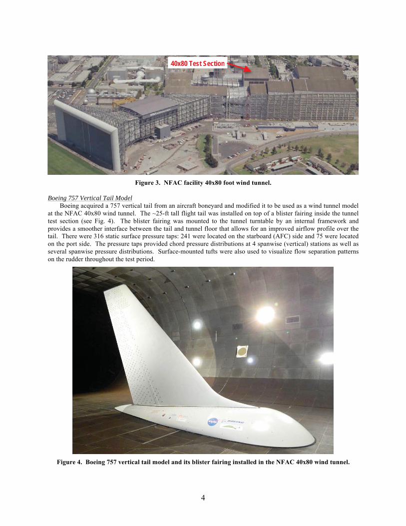
Figure 3. NFAC facility 40x80 foot wind tunnel.
Boeing 757 Vertical Tail Model
Boeing acquired a 757 vertical tail from an aircraft boneyard and modified it to be used as a wind tunnel model at the NFAC 40x80 wind tunnel. The ~25-ft tall flight tail was installed on top of a blister fairing inside the tunnel test section (see Fig. 4). The blister fairing was mounted to the tunnel turntable by an internal framework and provides a smoother interface between the tail and tunnel floor that allows for an improved airflow profile over the tail. There were 316 static surface pressure taps: 241 were located on the starboard (AFC) side and 75 were located on the port side. The pressure taps provided chord pressure distributions at 4 spanwise (vertical) stations as well as several spanwise pressure distributions. Surface-mounted tufts were also used to visualize flow separation patterns on the rudder throughout the test period.
Figure 4. Boeing 757 vertical tail model and its blister fairing installed in the NFAC 40x80 wind tunnel.
40x80 Test Section
5
Sweeping Jet AFC System The NASA ERA project contributed the sweeping jet AFC system with the support of the California Institute of
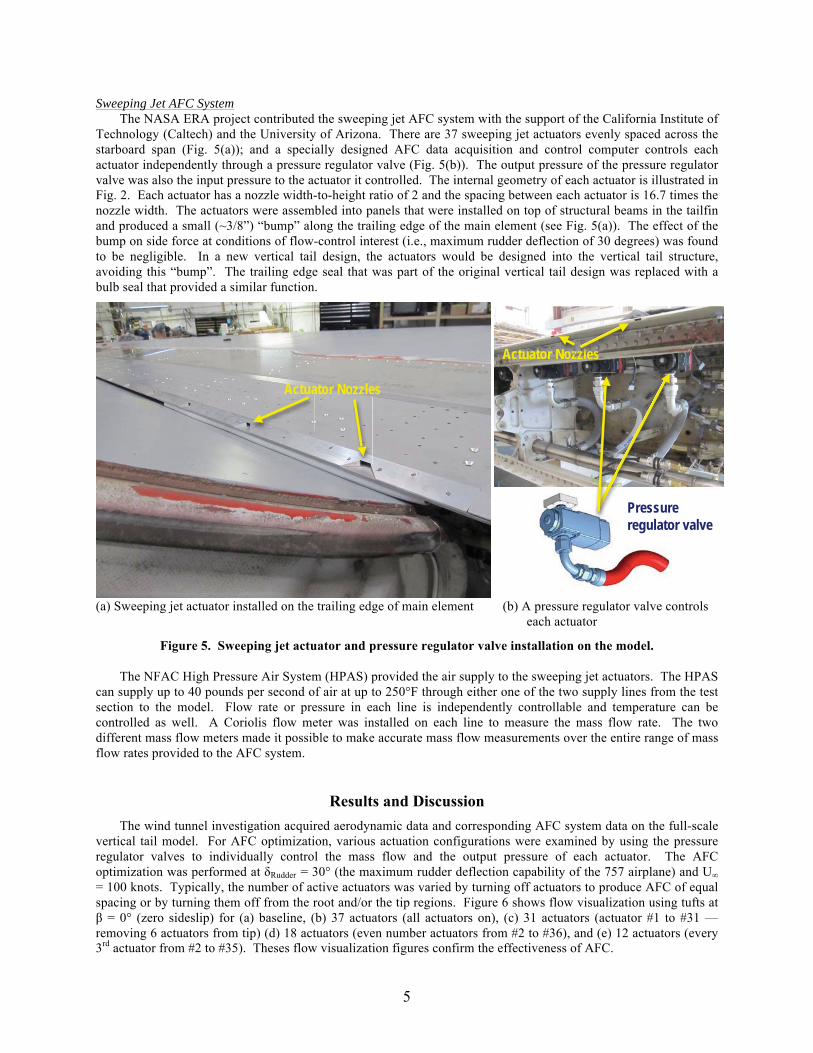
Technology (Caltech) and the University of Arizona. There are 37 sweeping jet actuators evenly spaced across the starboard span (Fig. 5(a)); and a specially designed AFC data acquisition and control computer controls each actuator independently through a pressure regulator valve (Fig. 5(b)). The output pressure of the pressure regulator valve was also the input pressure to the actuator it controlled. The internal geometry of each actuator is illustrated in Fig. 2. Each actuator has a nozzle width-to-height ratio of 2 and the spacing between each actuator is 16.7 times the nozzle width. The actuators were assembled into panels that were installed on top of structural beams in the tailfin and produced a small (~3/8”) “bump” along the trailing edge of the main element (see Fig. 5(a)). The effect of the bump on side force at conditions of flow-control interest (i.e., maximum rudder deflection of 30 degrees) was found to be negligible. In a new vertical tail design, the actuators would be designed into the vertical tail structure, avoiding this “bump”. The trailing edge seal that was part of the original vertical tail design was replaced with a bulb seal that provided a similar function.
(a) Sweeping jet actuator installed on the trailing edge of main element (b) A pressure regulator valve controls each actuator
Figure 5. Sweeping jet actuator and pressure regulator valve installation on the model. The NFAC High Pressure Air System (HPAS) provided the air supply to the sweeping jet actuators. The HPAS
can supply up to 40 pounds per second of air at up to 250°F through either one of the two supply lines from the test section to the model. Flow rate or pressure in each line is independently controllable and temperature can be controlled as well. A Coriolis flow meter was installed on each line to measure the mass flow rate. The two different mass flow meters made it possible to make accurate mass flow measurements over the entire range of mass flow rates provided to the AFC system.
Results and Discussion The wind tunnel investigation acquired aerodynamic data and corresponding AFC system data on the full-scale vertical tail model. For AFC optimization, various actuation configurations were examined by using the pressure regulator valves to individually control the mass flow and the output pressure of each actuator. The AFC optimization was performed at δRudder = 30° (the maximum rudder deflection capability of the 757 airplane) and U∞= 100 knots. Typically, the number of active actuators was varied by turning off actuators to produce AFC of equal spacing or by turning them off from the root and/or the tip regions. Figure 6 shows flow visualization using tufts at β = 0° (zero sideslip) for (a) baseline, (b) 37 actuators (all actuators on), (c) 31 actuators (actuator #1 to #31 — removing 6 actuators from tip) (d) 18 actuators (even number actuators from #2 to #36), and (e) 12 actuators (every 3rd actuator from #2 to #35). Theses flow visualization figures confirm the effectiveness of AFC.
Actuator Nozzles
Actuator Nozzles
Pressure regulator valve
Actua
Pressure
zzzzzllllllelelelesNoN zzzzzz
6
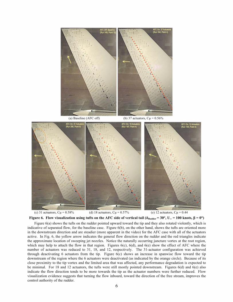
(a) Baseline (AFC off) (b) 37 actuators, Cμ = 0.56%
(c) 31 actuators, Cμ = 0.58% (d) 18 actuators, Cμ = 0.57% (e) 12 actuators, Cμ = 0.44
Figure 6. Flow visualization using tufts on the AFC side of vertical tail (δRudder = 30°, U∞ = 100 knots, β = 0°) Figure 6(a) shows the tufts on the rudder pointed upward toward the tip and they also rotated violently, which is indicative of separated flow, for the baseline case. Figure 6(b), on the other hand, shows the tufts are oriented more in the downstream direction and are steadier (more apparent in the video) for the AFC case with all of the actuators active. In Fig. 6, the yellow arrow indicates the general flow direction on the rudder and the red triangles indicate the approximate location of sweeping jet nozzles. Notice the naturally occurring juncture vortex at the root region, which may help to attach the flow in that region. Figures 6(c), 6(d), and 6(e) show the effect of AFC where the number of actuators was reduced to 31, 18, and 12, respectively. The 31-actuator configuration was achieved through deactivating 6 actuators from the tip. Figure 6(c) shows an increase in spanwise flow toward the tip downstream of the region where the 6 actuators were deactivated (as indicated by the orange circle). Because of its close proximity to the tip vortex and the limited area that was affected, any performance degradation is expected to be minimal. For 18 and 12 actuators, the tufts were still mostly pointed downstream. Figures 6(d) and 6(e) also indicate the flow direction tends to be more towards the tip as the actuator numbers were further reduced. Flow visualization evidence suggests that turning the flow inboard, toward the direction of the free stream, improves the control authority of the rudder.
7
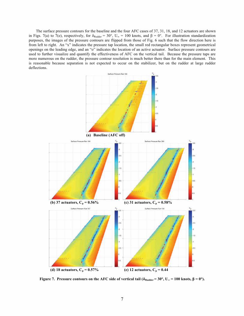
The surface pressure contours for the baseline and the four AFC cases of 37, 31, 18, and 12 actuators are shown in Figs. 7(a) to 7(e), respectively, for δRudder = 30°, U∞ = 100 knots, and β = 0°. For illustration standardization purposes, the images of the pressure contours are flipped from those of Fig. 6 such that the flow direction here is from left to right. An “x” indicates the pressure tap location, the small red rectangular boxes represent geometrical openings on the leading edge, and an “o” indicates the location of an active actuator. Surface pressure contours are used to further visualize and quantify the effectiveness of AFC on the vertical tail. Because the pressure taps are more numerous on the rudder, the pressure contour resolution is much better there than for the main element. This is reasonable because separation is not expected to occur on the stabilizer, but on the rudder at large rudder deflections.
(a) Baseline (AFC off)
(b) 37 actuators, Cμ = 0.56% (c) 31 actuators, Cμ = 0.58%
(d) 18 actuators, Cμ = 0.57% (e) 12 actuators, Cμ = 0.44
Figure 7. Pressure contours on the AFC side of vertical tail (δRudder = 30°, U∞ = 100 knots, β = 0°).
8
Sweeping jet actuation increased the suction pressure along the rudder’s hinge line and it did so across almost the entire span. Pressure contours for all AFC cases shown also indicated a better pressure recovery near the trailing edge. The AFC-induced attached flow is fairly uniform across the rudder span at all momentum coefficients shown. Comparing Figs. 7(b) and 7(c), there is virtually no change in the suction pressure contour by eliminating the 6 actuators nearest to the tip of the vertical tail. The suction pressure levels and the general shape of the pressure contours were not significantly affected by a further reduction in the number of AFC actuators (i.e., 18 and 12 actuators distributed across the entire span) at nearly constant momentum. For all of the configurations presented, the AFC maintains its effectiveness at flow separation control when the momentum coefficient is roughly matched (~0.5%).
(a) Baseline (AFC off)
(b) 37 actuators, Cμ = 0.57% (c) 31 actuators, Cμ = 0.59%
(d) 18 actuators, Cμ = 0.56% (e) 12 actuators, Cμ = 0.50%
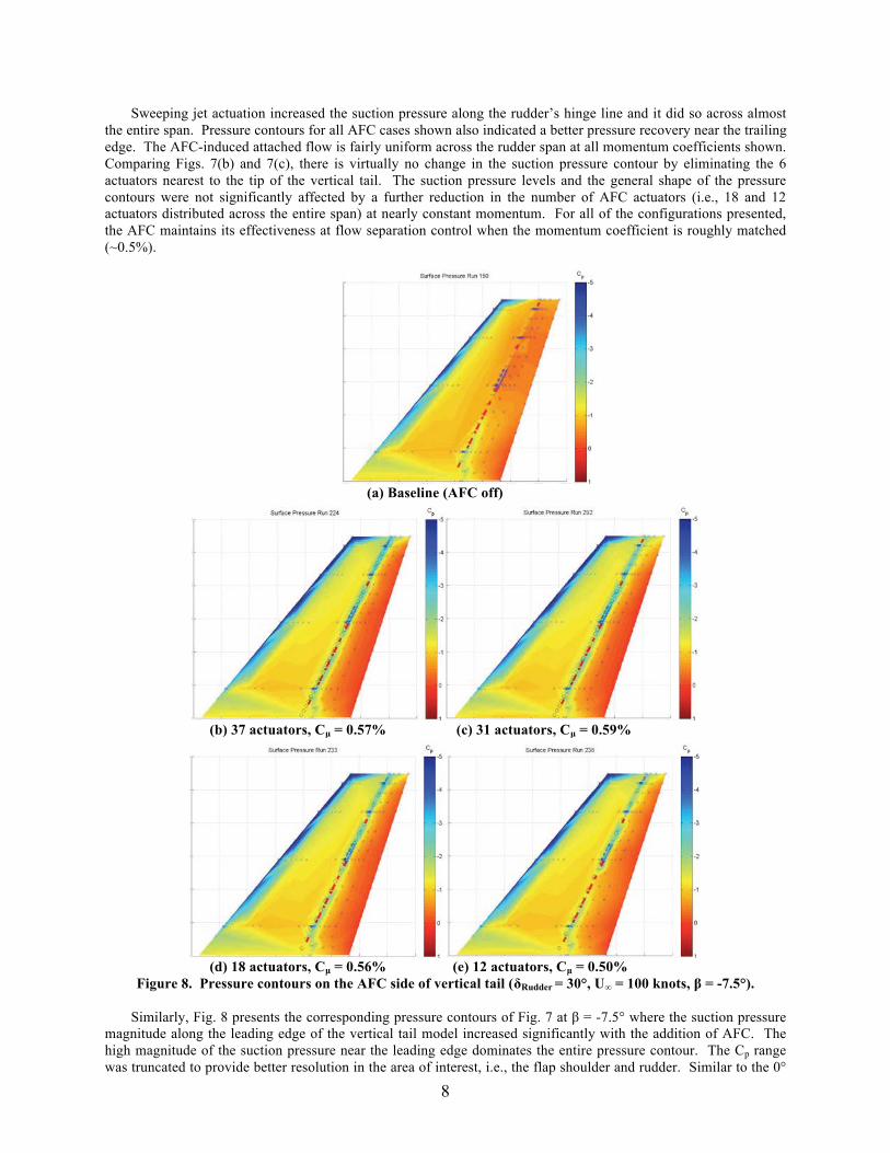
Figure 8. Pressure contours on the AFC side of vertical tail (δRudder = 30°, U∞ = 100 knots, β = -7.5°). Similarly, Fig. 8 presents the corresponding pressure contours of Fig. 7 at β = -7.5° where the suction pressure magnitude along the leading edge of the vertical tail model increased significantly with the addition of AFC. The high magnitude of the suction pressure near the leading edge dominates the entire pressure contour. The Cp range was truncated to provide better resolution in the area of interest, i.e., the flap shoulder and rudder. Similar to the 0°
9
sideslip case, the AFC appears to affect the pressure distribution most significantly near the rudder shoulder. Improved pressure recovery at the trailing edge of the rudder is also apparent, indicating that separation has been reduced. The biggest difference between the two sideslip angles is the shifting of the suction peak from the hinge-line location for zero sideslip (β = 0°) to the main element leading-edge location for β = -7.5°. Another slightly more subtle observation is that the suction pressure near mid-span at the rudder shoulder is reduced in magnitude as the number of actuators is reduced. Whereas for the 0° sideslip case, the spanwise pressure distribution along the rudder shoulder remained more uniform across the actuation cases presented. As illustrated in the tuft flow visualization of Fig. 6, the juncture vortex enhanced by seepage of air from the high-pressure side of the rudder helps to attach the flow in the root region (Fig. 6(a)), and therefore, there is less possibility for AFC to impact the suction pressures in that region for both sideslip angles (Figs. 7 and 8). The increased suction pressure farther downstream along the rudder hinge line at both sideslip angles with AFC applied should increase the distance between the tail’s aerodynamic center and the center of the gravity of the aircraft, which should provide an increase in yaw control authority. The root and tip regions of the vertical tail are dominated by the existence of the juncture vortex and tip vortex, respectively. This is quite apparent from CFD simulations (not shown) and is indicated by the surface tufts and pressure distributions. Thus, the question arises whether a desired side force level can be achieved by deactivating actuation in these regions, reducing the input required and optimizing the AFC system. The current root and tip actuation removal results are consistent with the subscale test result reported by Seele et al. [6]. Up to around 15% of the actuators could be removed from the tip without significant performance degradation. In the current study, the deactivation of the 6 actuators nearest to the tip resulted in a 31-actuator configuration. This reduced-actuator configuration exhibited greater side force enhancement compared to the 37-actuator configuration and did so with less mass flow, lower momentum, and a potentially simpler plumbing system.
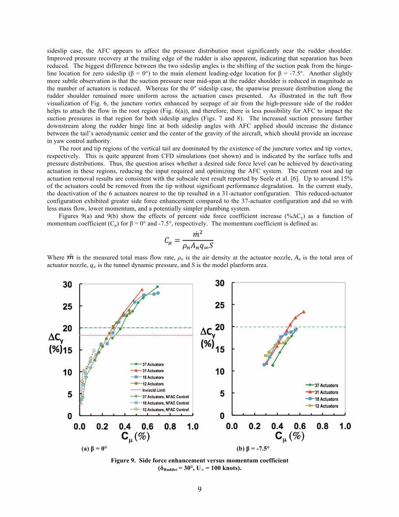
Figures 9(a) and 9(b) show the effects of percent side force coefficient increase (%ΔCy) as a function of momentum coefficient (Cμ) for β = 0° and -7.5°, respectively. The momentum coefficient is defined as:
Where is the measured total mass flow rate, ρn is the air density at the actuator nozzle, An is the total area of actuator nozzle, q∞ is the tunnel dynamic pressure, and S is the model planform area.
(a) β = 0° (b) β = -7.5°
Figure 9. Side force enhancement versus momentum coefficient (δRudder = 30°, U∞ = 100 knots).
10
The %ΔCy of each plot in Fig. 9 is normalized by the baseline (AFC off) Cy at its respective β. The theoretical inviscid performance of the vertical tail without AFC (calculated using CFD) is also shown for β = 0° for comparison (Fig. 9(a)). It is provided as an indicator of system efficiency for flow separation control, as opposed to circulation control. A 20% increase in side force was selected as a performance goal based on earlier system integration studies. The %ΔCy versus Cμ curves roughly collapsed into a single curve for each respective β. However, there were some differences. Most striking is that 31 actuators provided larger sideforce increments than the 37-actuator case at moderate to high momentum coefficients as did 18 actuators. A similar behavior was observed at -7.5 degrees sideslip. Figure 9(a) shows several actuator configurations could meet the 20% side force increase at β = 0° with Cμ greater than ~0.3%. Figure 9(a) also shows the results of using the NFAC facility valve to control lower mass flow (Cμ ≤ ~0.2%) through the main supply air line instead of individually through pressure regulator valves for 37, 18, and 12 actuators. The facility valve control produced similar side force increment trends as the pressure regulator valve control, but did so a little more efficiently.
Figure 9(b) shows a ΔCμ of approximately 0.2% (Cμ increased by a factor of 1.67) is needed to achieve the 20% side force enhancement due to the higher baseline (AFC off) value of Cy at β = -7.5°. Although a number of actuator configurations (actuator number ≥ 12) could meet the 20% ΔCy at β = 0°, only the 37- and 31-actuator configurations could meet the performance standard with certainty at β = -7.5° for Cμ ≤ 0.6%. From a system integration perspective, the 31-actuator configuration is also considered simpler and easier to implement.
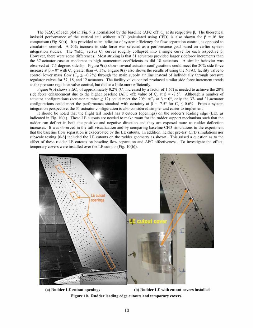
It should be noted that the flight tail model has 8 cutouts (openings) on the rudder’s leading edge (LE), as indicated in Fig. 10(a). These LE cutouts are needed to make room for the rudder support mechanism such that the rudder can deflect in both the positive and negative direction and they are exposed more as rudder deflection increases. It was observed in the tuft visualization and by comparing baseline CFD simulations to the experiment that the baseline flow separation is exacerbated by the LE cutouts. In addition, neither pre-test CFD simulations nor subscale testing [6-8] included the LE cutouts on the rudder geometry as shown. This raised a question as to the effect of these rudder LE cutouts on baseline flow separation and AFC effectiveness. To investigate the effect, temporary covers were installed over the LE cutouts (Fig. 10(b)).
(a) Rudder LE cutout openings (b) Rudder LE with cutout covers installed
Figure 10. Rudder leading edge cutouts and temporary covers.
11
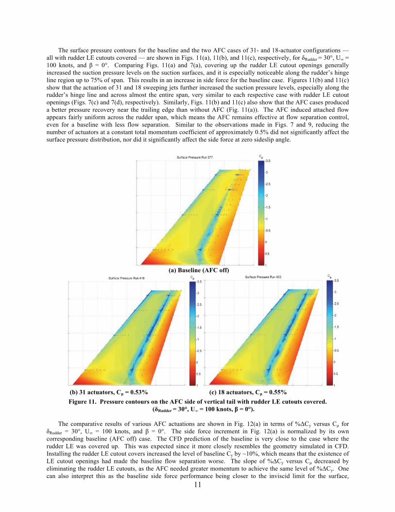
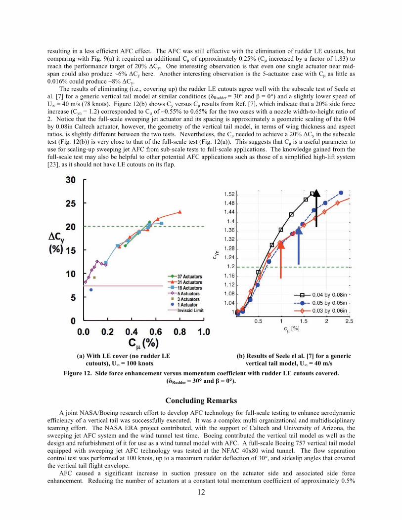
The surface pressure contours for the baseline and the two AFC cases of 31- and 18-actuator configurations — all with rudder LE cutouts covered — are shown in Figs. 11(a), 11(b), and 11(c), respectively, for δRudder = 30°, U∞ = 100 knots, and β = 0°. Comparing Figs. 11(a) and 7(a), covering up the rudder LE cutout openings generally increased the suction pressure levels on the suction surfaces, and it is especially noticeable along the rudder’s hinge line region up to 75% of span. This results in an increase in side force for the baseline case. Figures 11(b) and 11(c) show that the actuation of 31 and 18 sweeping jets further increased the suction pressure levels, especially along the rudder’s hinge line and across almost the entire span, very similar to each respective case with rudder LE cutout openings (Figs. 7(c) and 7(d), respectively). Similarly, Figs. 11(b) and 11(c) also show that the AFC cases produced a better pressure recovery near the trailing edge than without AFC (Fig. 11(a)). The AFC induced attached flow appears fairly uniform across the rudder span, which means the AFC remains effective at flow separation control, even for a baseline with less flow separation. Similar to the observations made in Figs. 7 and 9, reducing the number of actuators at a constant total momentum coefficient of approximately 0.5% did not significantly affect the surface pressure distribution, nor did it significantly affect the side force at zero sideslip angle.
(a) Baseline (AFC off)
(b) 31 actuators, Cμ = 0.53% (c) 18 actuators, Cμ = 0.55%
Figure 11. Pressure contours on the AFC side of vertical tail with rudder LE cutouts covered. (δRudder = 30°, U∞ = 100 knots, β = 0°).
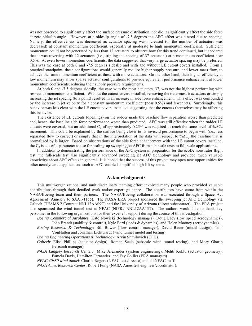
The comparative results of various AFC actuations are shown in Fig. 12(a) in terms of %ΔCy versus Cμ for
δRudder = 30°, U∞ = 100 knots, and β = 0°. The side force increment in Fig. 12(a) is normalized by its own corresponding baseline (AFC off) case. The CFD prediction of the baseline is very close to the case where the rudder LE was covered up. This was expected since it more closely resembles the geometry simulated in CFD. Installing the rudder LE cutout covers increased the level of baseline Cy by ~10%, which means that the existence of LE cutout openings had made the baseline flow separation worse. The slope of %ΔCy versus Cμ decreased by eliminating the rudder LE cutouts, as the AFC needed greater momentum to achieve the same level of %ΔCy. One can also interpret this as the baseline side force performance being closer to the inviscid limit for the surface,
12
resulting in a less efficient AFC effect. The AFC was still effective with the elimination of rudder LE cutouts, but comparing with Fig. 9(a) it required an additional Cμ of approximately 0.25% (Cμ increased by a factor of 1.83) to reach the performance target of 20% ΔCy. One interesting observation is that even one single actuator near mid-span could also produce ~6% ΔCy here. Another interesting observation is the 5-actuator case with Cμ as little as 0.016% could produce ~8% ΔCy.
The results of eliminating (i.e., covering up) the rudder LE cutouts agree well with the subscale test of Seele et al. [7] for a generic vertical tail model at similar conditions (δRudder = 30° and β = 0°) and a slightly lower speed of U∞ = 40 m/s (78 knots). Figure 12(b) shows Cy versus Cμ results from Ref. [7], which indicate that a 20% side force increase (Cyn = 1.2) corresponded to Cμ of ~0.55% to 0.65% for the two cases with a nozzle width-to-height ratio of 2. Notice that the full-scale sweeping jet actuator and its spacing is approximately a geometric scaling of the 0.04 by 0.08in Caltech actuator, however, the geometry of the vertical tail model, in terms of wing thickness and aspect ratios, is slightly different between the two tests. Nevertheless, the Cμ needed to achieve a 20% ΔCy in the subscale test (Fig. 12(b)) is very close to that of the full-scale test (Fig. 12(a)). This suggests that Cμ is a useful parameter to use for scaling-up sweeping jet AFC from sub-scale tests to full-scale applications. The knowledge gained from the full-scale test may also be helpful to other potential AFC applications such as those of a simplified high-lift system [23], as it should not have LE cutouts on its flap.
(a) With LE cover (no rudder LE
cutouts), U∞ = 100 knots (b) Results of Seele el al. [7] for a generic
vertical tail model, U∞ = 40 m/s Figure 12. Side force enhancement versus momentum coefficient with rudder LE cutouts covered.
(δRudder = 30° and β = 0°).
Concluding Remarks A joint NASA/Boeing research effort to develop AFC technology for full-scale testing to enhance aerodynamic
efficiency of a vertical tail was successfully executed. It was a complex multi-organizational and multidisciplinary teaming effort. The NASA ERA project contributed, with the support of Caltech and University of Arizona, the sweeping jet AFC system and the wind tunnel test time. Boeing contributed the vertical tail model as well as the design and refurbishment of it for use as a wind tunnel model with AFC. A full-scale Boeing 757 vertical tail model equipped with sweeping jet AFC technology was tested at the NFAC 40x80 wind tunnel. The flow separation control test was performed at 100 knots, up to a maximum rudder deflection of 30°, and sideslip angles that covered the vertical tail flight envelope.
AFC caused a significant increase in suction pressure on the actuator side and associated side force enhancement. Reducing the number of actuators at a constant total momentum coefficient of approximately 0.5%
13
was not observed to significantly affect the surface pressure distribution, nor did it significantly affect the side force at zero sideslip angle. However, at a sideslip angle of -7.5 degrees the AFC effect was altered due to spacing. Namely, the effectiveness was decreased as actuator spacing was increased (or the number of actuators was decreased) at constant momentum coefficient, especially at moderate to high momentum coefficient. Sufficient momentum could not be generated by less than 12 actuators to observe how far this trend continued, but it appeared that it was reversing with 12 actuators (i.e., tripling the spacing of 37 actuators) at a momentum coefficient near 0.5%. At even lower momentum coefficients, the data suggested that very large actuator spacing may be preferred. This was the case at both 0 and -7.5 degrees sideslip and with and without LE cutout covers installed. From a practical standpoint, these configurations would generally require higher supply pressure, and lower mass flow, to achieve the same momentum coefficient as those with more actuators. On the other hand, their higher efficiency at low momentum may allow sparse actuator configurations to provide equivalent performance enhancement at lower momentum coefficients, reducing their supply pressure requirements.
At both 0 and -7.5 degrees sideslip, the case with the most actuators, 37, was not the highest performing with respect to momentum coefficient. Without the cutout covers installed, removing the outermost 6 actuators or simply increasing the jet spacing (to a point) resulted in an increase in side force enhancement. This effect was confounded by the increase in jet velocity for a constant momentum coefficient (near 0.5%) and fewer jets. Surprisingly, this behavior was less clear with the LE cutout covers installed, suggesting that the cutouts themselves may be affecting this behavior.
The existence of LE cutouts (openings) on the rudder made the baseline flow separation worse than predicted and, hence, the baseline side force performance worse than predicted. AFC was still effective when the rudder LE cutouts were covered, but an additional Cμ of approximately 0.25% was required to reach the same level of %ΔCy increment. This could be explained by the surface being closer to its inviscid performance to begin with (i.e., less separated flow to correct) or simply that in the interpretation of the data with respect to %ΔCy the baseline that is normalized by is larger. Based on observations of the side force enhancement with the LE cutout covers installed, the Cμ is a useful parameter to use for scaling-up sweeping jet AFC from sub-scale tests to full-scale applications.
In addition to demonstrating the performance of the AFC system in preparation for the ecoDemonstrator flight test, the full-scale test also significantly advanced sweeping jet AFC technology and provided much valuable knowledge about AFC effects in general. It is hoped that the success of this project may open new opportunities for other aerodynamic applications such as AFC-enabled simplified high-lift systems.
Acknowledgments
This multi-organizational and multidisciplinary teaming effort involved many people who provided valuable contributions through their detailed work and/or expert guidance. The contributors have come from within the NASA/Boeing team and their partners. The NASA/Boeing collaboration was executed through a Space Act Agreement (Annex 8 to SAA1-1155). The NASA ERA project sponsored the sweeping jet AFC technology via Caltech (TEAMS 2 Contract NNL12AA09C) and the University of Arizona (direct subcontract). The ERA project also sponsored the wind tunnel test at NFAC (NIPR# NNL12AA13T). The authors would like to thank key personnel in the following organizations for their excellent support during the course of this investigation:
Boeing Commercial Airplanes: Kate Nowicki (technology manager), Doug Lacy (low speed aerodynamics), John Brandt (stability & control), Kyle Ford (loads & dynamics), and Helen Mooney (aerodynamics).
Boeing Research & Technology: Bill Bower (flow control manager), David Bauer (model design), Tom VonHatten and Jonathan Lichtwardt (wind tunnel model and testing).
Boeing Engineering Operations & Technology: Arvin Shmilovich (CFD). Caltech: Elisa Phillips (actuator design), Roman Seele (subscale wind tunnel testing), and Mory Gharib
(research manager). NASA Langley Research Center: Mike Alexander (system engineering), Mehti Koklu (actuator geometry),
Pamela Davis, Hamilton Fernandez, and Fay Collier (ERA managers). NFAC 40x80 wind tunnel: Charlie Rogers (NFAC test director) and all NFAC staff. NASA Ames Research Center: Robert Fong (NASA Ames test engineer/coordinator).
14
References [1] Collier, F. S., Thomas, R, Nickol, C. A., Lee, Chi-Ming, Tong, M., “Environmentally Responsible Aviation –
Real Solutions for Environmental Challenges Facing Aviation,” 27th International Congress of the Aeronautical Sciences, Paper No. 802, Nice, France, September 19–24, 2010.
[2] Bezos-O’Conner, G.M., Mangelsdorf, M.F., Maliska, H.A., Washburn, A.E., Wahls, R.A., “Fuel Efficiencies Through Airframe Improvements,” AIAA 2011-3530, 29th AIAA Applied Aerodynamics Conference, Honolulu, HI, June 27–30, 2011.
[3] Cattafesta III, L.N. and Sheplak, M., “Actuators for Active Flow Control”, Annual Review of Fluid Mechanics, Vol. 43, Issue 1, August 2010, pp. 247-272.
[4] Rathay, N., Boucher, M., Amitay, M. and Whalen, E., "Performance Enhancement of a Vertical Stabilizer using Synthetic Jet Actuators: No Sideslip", AIAA 2012-0071, 50th AIAA Aerospace Sciences Meeting, Nashville, TN, January 9–12, 2012.
[5] Rathay, N., Boucher, M., Amitay, M. and Whalen, E., "Performance Enhancement of a Vertical Stabilizer using Synthetic Jet Actuators: Non-zero Sideslip", AIAA 2012-2657, 6th AIAA Flow Control Conference, New Orleans, LA, June 25–28, 2012.
[6] Seele, R., Graff, E., Gharib, M., Taubert, L., Lin, J. and Wygnanski, I., “Improving Rudder Effectiveness with Sweeping Jet Actuators,” AIAA 2012-3244, 6th AIAA Flow Control Conference, New Orleans, LA, June 25–28, 2012.
[7] Seele, R., Graff, E., Lin, J. and Wygnanski, I., “Performance Enhancement of a Vertical Tail Model with Sweeping Jet Actuators,” AIAA 2013-0411, 51st AIAA Aerospace Sciences Meeting, Grapevine, Texas, January 7–10, 2013.
[8] Graff, E., Seele, R., Lin, J., and Wygnanski, I., “Sweeping Jet Actuators – A New Design Tool for High Lift Generation,” NATO Workshop on Innovative Control Effectors for Military Vehicles (AVT-215), Stockholm, Sweden, May 2013.
[9] Raman, G. and Raghu, S., “Cavity Resonance Suppression Using Miniature Fluidic Oscillators”, AIAA Journal, Vol. 42, No. 12, December 2004, pp. 2608-2611.
[10] Guyot, D., Bobusch, B., Paschereit, C.O., and Raghu, S., “Active Combustion Control Using a Fluidic Oscillator for Asymmetric Fuel Flow Modulation”, AIAA 2008-4956, 44th AIAA/ASME/SAE/ASEE Joint Propulsion Conference & Exhibit, Hartford, CT, July 21–23, 2008.
[11] Cerretelli, C., Gharaibah, E., Toplack, G., Gupta, A., and Wuerz, W., “Unsteady Separation Control for Wind Turbine Applications at Full Scale Reynolds Numbers”, AIAA 2009-0380, 47th AIAA Aerospace Sciences Meeting, Orlando, FL, January 5–8, 2009.
[12] Cerretelli, C. and Kirtley, K., “Boundary Layer Separation Control with Fluidic Oscillators”, Journal of Turbomachinery, Vol. 131, October 2009.
[13] Seifert, A., Stalnov, O., Sperber, D., Arwatz, G., Palei, V., David, S., Dayan, I., and Fono, I., “Large Trucks Drag Reduction Using Active Flow Control”, AIAA 2008-0743, 47th AIAA Aerospace Sciences Meeting and Exhibit, Reno, NV, January 7–10, 2008.
[14] Lucas, N., Taubert, L., Woszidlo, R., Wygnanski, I., and McVeigh, M. A., “Discrete Sweeping Jets as Tools for Separation Control,” AIAA 2008-3868, 4th AIAA Flow Control Conference, Seattle, WA, June 23–26, 2008.
[15] Seele, R., Tewes, P., Woszidlo, R., McVeigh, M., Lucas, N., and Wygnanski, I., “Discrete Sweeping Jets as Tools for Improving the Performance of the V-22”, AIAA Journal of Aircraft, Vol. 46, No. 6, 2009, pp. 2098-2106.
[16] Phillips, E., Woszidlo, R., and Wygnanski, J., “The Dynamics of Separation Control on a Rapidly Actuated Flap”, AIAA 2010-4246, 5th AIAA Flow Control Conference, Chicago, IL, June 28–July 1, 2010.
[17] DeSalvo, M., Whalen, E., and Glezer, A., “High-Lift Enhancement Using Active Flow Control”, AIAA 2011-3355, 29th AIAA Applied Aerodynamics Conference, Honolulu, HI, June 27–30, 2011.
[18] Tewes, P., Taubert, L., and Wygnanski, J., “On the Use of Sweeping Jets to Augment the Lift of a λ-Wing”, AIAA 2010-4689, 5th AIAA Flow Control Conference, Chicago, IL, June 28–July 1, 2010.
[19] Vatsa, V., Koklu, M and Wygnanski, I., "Numerical Simulation of Fluidic Actuators for Flow Control Applications", AIAA-2012-3239, 6th AIAA Flow Control Conference, New Orleans, LA, June 26–29, 2012.
[20] Koklu, M., Melton, L.M., “Sweeping Jet Actuator in a Quiescent Environment”, AIAA 2013-2477, 43rd AIAA Fluid Dynamics Conference, San Diego, June 24–27, 2013.
[21] Woszidlo, R. and Wygnanski, I., “Parameters Governing Separation Control with Sweeping Jet Actuators”, AIAA 2011-3172, 29th AIAA Applied Aerodynamics Conference, Honolulu, HI, June 27–30, 2011.
15
[22] Woszidlo, R., Nawroth, H., Raghu, S., and Wygnanski, I., “Parametric Study of Sweeping Jet Actuators for Separation Control”, AIAA 2010-4247, 5th AIAA Flow Control Conference, Chicago, IL, June 28–July 1, 2010.
[23] Melton, L. P., Schaeffler, N. W., and Lin, J. C., “High-Lift System for a Supercritical Airfoil: Simplified by Active Flow Control,” AIAA Paper 2007-0707, 45th AIAA Aerospace Sciences Meeting and Exhibit, Reno, NV, January 8-11, 2007.
[24] http://rotorcraft.arc.nasa.gov/Research/facilities/windtunnels.html