Embed Size (px)
Citation preview

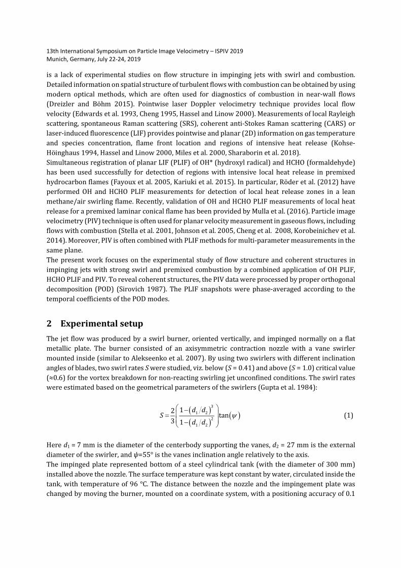
13th International Symposium on Particle Image Velocimetry – ISPIV 2019
Munich, Germany, July 22-24, 2019
Flow structure and combustion in an impinging jet
with swirl studied simultaneously by stereo PIV,
OH PLIF and HCHO PLIF
Roman Tolstoguzov1,2, Dmitriy Sharaborin1,2, Dmitriy Markovich1,2,
Vladimir Dulin1,2*
1Kutateladze Institute of Thermophysics, Siberian Branch of the Russian Academy of Sciences,
Novosibirsk, Russia
2 Novosibirsk State University, Novosibirsk, Russia
Abstract
The present paper reports on an experimental study of flow structure and coherent structures in
impinging jets with strong swirl and combustion of lean propane/air mixture by a combined
application of OH PLIF, HCHO PLIF and PIV. To reveal coherent structures, the experimental data are
processed by proper orthogonal decomposition (POD). The decomposition has revealed two kinds of
large-scale organized flow structures. One kind corresponds to vortex structures formed in mixing
layers of the swirling jets and causing deformations of the combustion zone. Another corresponds to
large-scale flow oscillations during jet impingement onto the surface, which are found to be
statistically correlated with fluctuations of HCHO fluorescence intensity inside the recirculation zone.
1 Introduction
One of the flow configurations, where combustion takes place near walls, is a jet-flame impinging on
an obstacle. In particular, impinging jet-flames are used for intensive heating of solid materials. Local
heat transfer conditions are determined by the flow structure and dynamics and by efficiency of fuel
combustion upstream the obstacle. Flow swirl is often organized to intensify combustion in jets. It
provides successive ignition and stable combustion (without blow-off) near the nozzle exit for a wide
range of flow rates of fuel and oxidizer. Organization of flow with strong swirl usually results in
breakdown of the swirling jet’s vortex core with formation of a central recirculation zone and
intensive velocity fluctuations near the nozzle (Billant et al. 1998, Oberleithner et al. 2011). This
features lead to intensification of heat and mass transfer and provide favorable conditions for efficient
fuel combustion in a compact volume (Syred and Beer 1974, Gupta et al. 1984, Weber and Dugué
1992), which allows design of compact heaters.
At the same time, as reported in a number of papers, swirl induces unsteady flow dynamics, which
may interfere with unsteady combustion modes. Most of the published experimental studies of
impinging jet-flames with combustion, including few works on turbulent jet-flames with swirl,
reports on temperature and heat flux distributions on the impinging surface (Luo et al. 2010, Singh et
al. 2012, Chander and Singh 2013, Singh and Chander 2013, Singh et al. 2014). Thus, currently there
13th International Symposium on Particle Image Velocimetry – ISPIV 2019
Munich, Germany, July 22-24, 2019
is a lack of experimental studies on flow structure in impinging jets with swirl and combustion.
Detailed information on spatial structure of turbulent flows with combustion can be obtained by using
modern optical methods, which are often used for diagnostics of combustion in near-wall flows
(Dreizler and Böhm 2015). Pointwise laser Doppler velocimetry technique provides local flow
velocity (Edwards et al. 1993, Cheng 1995, Hassel and Linow 2000). Measurements of local Rayleigh
scattering, spontaneous Raman scattering (SRS), coherent anti-Stokes Raman scattering (CARS) or
laser-induced fluorescence (LIF) provides pointwise and planar (2D) information on gas temperature
and species concentration, flame front location and regions of intensive heat release (Kohse-
Höinghaus 1994, Hassel and Linow 2000, Miles et al. 2000, Sharaborin et al. 2018).
Simultaneous registration of planar LIF (PLIF) of OH* (hydroxyl radical) and HCHO (formaldehyde)
has been used successfully for detection of regions with intensive local heat release in premixed
hydrocarbon flames (Fayoux et al. 2005, Kariuki et al. 2015). In particular, Röder et al. (2012) have
performed OH and HCHO PLIF measurements for detection of local heat release zones in a lean
methane/air swirling flame. Recently, validation of OH and HCHO PLIF measurements of local heat
release for a premixed laminar conical flame has been provided by Mulla et al. (2016). Particle image
velocimetry (PIV) technique is often used for planar velocity measurement in gaseous flows, including
flows with combustion (Stella et al. 2001, Johnson et al. 2005, Cheng et al. 2008, Korobeinichev et al.
2014). Moreover, PIV is often combined with PLIF methods for multi-parameter measurements in the
same plane.
The present work focuses on the experimental study of flow structure and coherent structures in
impinging jets with strong swirl and premixed combustion by a combined application of OH PLIF,
HCHO PLIF and PIV. To reveal coherent structures, the PIV data were processed by proper orthogonal
decomposition (POD) (Sirovich 1987). The PLIF snapshots were phase-averaged according to the
temporal coefficients of the POD modes.
2 Experimental setup
The jet flow was produced by a swirl burner, oriented vertically, and impinged normally on a flat
metallic plate. The burner consisted of an axisymmetric contraction nozzle with a vane swirler
mounted inside (similar to Alekseenko et al. 2007). By using two swirlers with different inclination
angles of blades, two swirl rates S were studied, viz. below (S = 0.41) and above (S = 1.0) critical value
(≈0.6) for the vortex breakdown for non-reacting swirling jet unconfined conditions. The swirl rates
were estimated based on the geometrical parameters of the swirlers (Gupta et al. 1984):
( )( )
( )3
1 2
2
1 2
12tan
3 1
d dS
d dψ
− = −
(1)
Here d1 = 7 mm is the diameter of the centerbody supporting the vanes, d2 = 27 mm is the external
diameter of the swirler, and ψ=55° is the vanes inclination angle relatively to the axis.
The impinged plate represented bottom of a steel cylindrical tank (with the diameter of 300 mm)
installed above the nozzle. The surface temperature was kept constant by water, circulated inside the
tank, with temperature of 96 °C. The distance between the nozzle and the impingement plate was
changed by moving the burner, mounted on a coordinate system, with a positioning accuracy of 0.1

13th International Symposium on Particle Image Velocimetry – ISPIV 2019
Munich, Germany, July 22-24, 2019
mm. Flow cases with nozzle-to-plate distance H equal to3d and 1d were investigated, as well as the
unconfined flame configuration. Flow rates of the fuel (propane) and air were controlled by mass flow
meters (Bronkhorst). The equivalence ratio of the mixture issued from the nozzle was 0.7. The
Reynolds number of the jet determined by the bulk velocity of the air flow (U0 = 5 m/s), nozzle exit
diameter (d = 15 mm) and the viscosity of air was Re = 5 000. To provide PIV measurements, the air
flow was seeded by TiO2 particles with the mean size of approximately 0.5 μm.
The used stereoscopic PIV system included pair of CCD cameras (Bobcat IGV-B2020, 4 Mpix, 8 bit)
and double-head pulsed Nd:YAG laser (Beamtech Vlite 200, 532 nm, 7 ns pulse with 200 mJ) to
illuminate the tracer particles. The cameras were equipped with lenses (Sigma 50mm DG MACRO)
and narrow-band optical filters, which transmitted light scattered by the tracer particles at 532 nm
(± 5 nm). The laser beam was converted into a laser sheet by using a system of cylindrical and
spherical lenses. The OH PLIF consisted of a tunable pulsed dye laser (Sirah), pumped by a pulsed
Nd:YAG laser (QuantaRay), and UV-sensitive ICCD camera (Princeton instruments PI-MAX-4, 16 bit),
equipped with a UV-lens and band-pass optical filter. The average pulse energy of the tunable laser,
excited Q1(8) line of the A2Σ–X2Π (1–0) band, was approximately 5 mJ. The HCHO PLIF system
consisted of a pulsed Nd:YAG laser Quantel Brilliant B (355 nm, 8 ns pulse with 50 mJ), UV-sensitive
image intensifier (LaVision IRO) and sCMOS camera (LaVision, Imager sCMOS, 5 Mpix, 16 bit). The
image intensifier was equipped with a UV-lens and band-pass filter.
A system of optical elements was used to organize illumination of the measurement plane (in the
central cross-section) by laser sheets with thickness below 0.8 mm. The PLIF signal was collected
almost in the middle of the time interval between two PIV laser pulses. In both cases the exposure
time for each PLIF image was 200 ns. Time separation between two PIV laser pulses was 20 μs. An in-
house ActualFlow software, developed in the Institute of Thermophysics, was used to acquire and
process the data. The velocity fields were evaluated by an adaptive iterative cross-correlation
algorithm with continuous image shift and deformation (for definition see Scarano 2001). The final
size of the interrogation areas was 32×32 pixels. The spatial overlap rate between the neighbour
interrogation areas was 50%. The spatial resolution of the PIV system corresponded to approximately
1 mm. A set of images post-processing algorithms was used to process the PLIF images to minimize
effect of dark current and background luminosity, to correct for non-uniformity of the laser-sheet and
spatial sensitivity of the sensors.
Spatial calibration of the stereo PIV and PLIF cameras was performed by using a plane calibration
target and 3rd-order polynomial transforms. This was done by processing images of the calibration
target placed in five different positions in the normal-to-plane direction with the step of 0.5 mm. In
addition, to minimize the calibration error, an iterative correction procedure of possible
misalignment between the laser sheet and the target plane was applied (Coudert and Schon, 2001).
For almost entire measurement domain the mismatch between the actual locations of markers on the
target and their coordinates in the obtained calibration models was below 1 pixel. To ensure that PIV
and PLIF laser sheet planes were well aligned, a photo-sensitive paper was placed into the
measurement volume and exposed to a single shot of each laser prior to the measurements.
3 Results
Figure 1 shows photographs of the unconfined flames and time-averaged PIV and PLIF data. For the
low-swirl flow (S = 0.41) the flame is stabilized above the nozzle exit. According to the mean velocity

13th International Symposium on Particle Image Velocimetry – ISPIV 2019
Munich, Germany, July 22-24, 2019
field, there is a wake zone formed downstream the nozzle exit inside the core of the expanding
swirling jet. For the high-swirl flow (S = 1.0) there is a bubble-type central recirculation zone. The
flame front is stabilized in the inner mixing layer between the annular swirling jet and central
recirculation zone. The flame front penetrates inside the nozzle. Time-averaged OH PLIF signal
reveals regions with hot combustion products, containing H2O. On average. the HCHO PLIF reveals
location of the chemical reaction zone, which has a shape similar to the visible flame front in the
photographs.
Figures 2 and 3 shows flame images and time-averaged PIV and PLIF data for the swirling flame when
the cold impingement surface is located at 3d and 1d downstream the nozzle exit, respectively. For
the case H = 3d the flame shapes are similar to those for the unconfined configurations. The main
difference that for both swirl rates there are lengthy cone-like recirculation zones between the nozzle
and the impingement plate. The PLIF data shows that OH fluorescence inside the recirculation zone
is weak, which could be due to cooling of the reverse flow by the obstacle. Besides for the case of high
swirl (S = 1.0), HCHO fluorescence occurs not only near the visible flame front, but also inside the
recirculation zone. For H = 1d the separation distance is so small, that the flame front is deflected by
the surface and spreads along it. According to the PIV data, cone-like recirculation zones are also
present for both cases. On average, regions of OH and HCHO fluorescence have shape similar to that
of the flame. For the high-swirl case, the HCHO fluorescence is weak inside the recirculation zone, as
it is observed for the unconfined configuration.
In order to characterize coherent flow structures, the velocity data sets are processed by snapshot
POD via singular value decomposition (SVD) method:
( ) ( ) ( )1
,N
k q k q qq
t tα σ=
′ =∑u x φ x , (2)
where ( ) ( )1
1 M
i k j k ijkM
δ=
=∑φ x φ x and ( ) ( )1
1 N
i k j k ijk
t tN
α α δ=
=∑ (3)
The set of the fluctuating velocity fields [u′(x, t1)…u′(x, tN)] is represented as a finite series of the
products of the spatial orthonormal basis functions φq with non-dimensional temporal coefficients αq
and singular values σq. N and M are the number of the snapshots in the set and number of spatial point
in each snapshot, respectively. The singular values characterize amplitude (square root of the kinetic
energy of the velocity fluctuations) of each POD mode. Their spectra are shown in Figure 4. It is found
that the POD modes correspond to two different kinds of coherent structures. The examples are
shown in Figure 5.
The first and second POD modes for the case H/d = 3 demonstrate two different kinds of coherent
structures. The second POD mode is concluded to correspond to large-scale vortex structures formed
in mixing layers of the jet. According the phase-averaged fluorescence intensity, they produce
deformations of the reaction zone. In contrast, the first POD mode corresponds to large-scale flow
oscillations during jet impingement onto the surface. According to the phase-averaged fluctuations of
the HCHO PLIF signal, these large-scale flow motion are statistically correlated with variation of
HCHO intensity inside the central recirculation zone.

13th International Symposium on Particle Image Velocimetry – ISPIV 2019
Munich, Germany, July 22-24, 2019
Figure 1: Photographs of unconfined flames and time-averaged PIV and PLIF data.
0.41=S 1.0=S
×d ×d
×d ×d
×d ×d
×d ×d
OH PLIF OH PLIF
HCHO PLIF HCHO PLIF
×d ×d
×d ×d
[ ]a.u.

13th International Symposium on Particle Image Velocimetry – ISPIV 2019
Munich, Germany, July 22-24, 2019
Figure 2: Photographs of impinging flames (H/d = 3) and time-averaged PIV and PLIF data.
0.41, 3= =S H d 1.0, 3= =S H d
×d ×d
×d ×d
×d ×d
×d ×d
OH PLIF OH PLIF
HCHO PLIF HCHO PLIF
×d ×d
×d ×d

13th International Symposium on Particle Image Velocimetry – ISPIV 2019
Munich, Germany, July 22-24, 2019
Figure 3: Photographs of impinging flames (H/d = 1) and time-averaged PIV and PLIF data.
Figure 4: POD spectra for high-swirl flows (S = 1.0) and temporal coefficients for H/d=3.
-0.12 -0.06 0 0.06 0.12
-0.12
-0.06
0
0.06
0.12
0.41, 1= =S H d 1.0, 1= =S H d
×d
OH PLIF
HCHO PLIF
×d
×d
×d
×d
×d
×d
×d
×d
×d
×d
×d
1.0, 3= =S H d
( )2 itα
( )1 itα
i
2
2
1
σ
σ=∑
i
N
j
j
[ ]%1
3
==
H d
H d

13th International Symposium on Particle Image Velocimetry – ISPIV 2019
Munich, Germany, July 22-24, 2019
Figure 5: Spatial distributions of the first and second POD modes and corresponding phase-
averaged fluctuations of the HCHO PLIF intensity for S = 1.0, H/d =3.
4 Conclusion
The performed combined study of coherent flow structures by PIV and flame front deformations by
OH and HCHO PLIF in impinging swirling jets with premixed combustion has revealed two kinds of
large-scale organized flow structures. One kind corresponds to vortex structures formed in the mixing
layers of the jets. Another corresponds to large-scale flow oscillations during jet impingement onto
the surface, statistically correlated with HCHO intensity inside the central recirculation zone.
Acknowledgements
The research is supported by the Russian Science Foundation (grant No 16-19-10566).
References
Alekseenko SV, Bilsky AV, Dulin VM, and Markovich DM (2007). Experimental study of an impinging
jet with different swirl rates. International Journal of Heat and Fluid Flow 28(6): 1340-1359
Billant P, Chomaz JM, and Huerre P (1998). Experimental study of vortex breakdown in swirling jet.
Journal of Fluid Mechanics 376:183-219
Chander S and Singh G (2013). Effect of Helical Vane Swirler Geometry on Heat Transfer
Characteristics for Compressed Natural Gas/Air Swirling Flame Impinging on a Flat Surface. In
ASME 2013 International Mechanical Engineering Congress and Exposition (pp. V08AT09A018-
V08AT09A018). San Diego, California, USA, November 15–21
Cheng RK (1995). Velocity and scalar characteristics of premixed turbulent flames stabilized by weak
swirl. Combustion and Flame 101: 1-14
Cheng RK, Littlejohn D, Nazeer WA, Smith K (2008). Laboratory studies of the flow field
characteristics of low-swirl injectors for adaptation to fuel-flexible turbines. Journal of Engineering
for Gas Turbines and Power 130: 021501
1st POD mode
×d ×d
×d ×d
2nd POD mode

13th International Symposium on Particle Image Velocimetry – ISPIV 2019
Munich, Germany, July 22-24, 2019
Coudert SJ and Schon JP (2001) Back-projection algorithm with misalignment corrections for 2D3C
stereoscopic PIV. Measurement Science and Technology 12:1371–1381
Dreizler A and Böhm B (2015). Advanced laser diagnostics for an improved understanding of
premixed flame-wall interactions. Proceedings of the Combustion Institute 35(1): 37-64
Edwards CF, Fornaciari NR, Dunsky CM, Marx KD, and Ashurst WT (1993). Spatial structure of a
confined swirling flow using planar elastic scatter imaging and laser Doppler velocimetry. Fuel 72:
1151-1159
Fayoux A, Zähringer K, Gicquel O, and Rolon J (2005) Experimental and numerical determination of
heat release in counterflow premixed laminar flames. Proceedings of the Combustion Institute 30:
251-257
Gupta AK, Lilley DG, and Syred N (1984) Swirl flows. Kent, U.K.: Abacus Press
Hassel EP and Linow S (2000). Laser diagnostics for studies of turbulent combustion. Measurement
Science and Technology 11: R37-R57
Johnson MR, Littlejohn D, Nazeer WA, Smith KO, and Cheng RK (2005). A comparison of the flow fields
and emissions of high-swirl injectors and low-swirl injectors for lean premixed gas turbines.
Proceedings of the Combustion Institute 30:2867-2874
Kariuki J, Dowlut A, Yuan R, Balachandran R, and Mastorakos E (2015). Heat release imaging in
turbulent premixed methane-air flames close to blow-off. Proceedings of the Combustion Institute
35: 1443-1450
Kohse-Höinghaus K. (1994). Laser techniques for the quantitative detection of reactive intermediates
in combustion systems. Progress in Energy and Combustion Science 20: 203-279
Korobeinichev OP, Shmakov AG, Chernov AA, Markovich DM, Dulin VM, and Sharaborin DK (2014).
Spatial and temporal resolution of the particle image velocimetry technique in flame speed
measurements. Combustion, Explosion, and Shock Waves 50(5):510-517
Luo DD, Zhen HS, Leung CW, and Cheung CS (2010) Premixed flame impingement heat transfer with
induced swirl. International Journal of Heat and Mass Transfer 53(19-20): 4333-4336
Miles RB, Lempert WR, Forkey JN (2001) Laser Rayleigh scattering. Measurement Science and
Technology 12: R33-R51
Mulla IA, Dowlut A, Hussain T, Nikolaou ZM, Chakravarthy SR, Swaminathan N, and Balachandran R
(2016). Heat release rate estimation in laminar premixed flames using laser-induced fluorescence
of CH2O and H-atom. Combustion and Flame 165: 373-383
Oberleithner K, Sieber M, Nayeri CN, Paschereit CO, Petz C, Hege HC, Noack BR, and Wygnanski I
(2011) Three-dimensional coherent structures in a swirling jet undergoing vortex breakdown:
Stability analysis and empirical mode construction. Journal of Fluid Mechanics 679: 383–414
Röder M, Dreier T, and Schulz C (2012). Simultaneous measurement of localized heat release with
OH/CH2O-LIF imaging and spatially integrated OH∗ chemiluminescence in turbulent swirl flames.
Applied Physics B 107(3): 611-617

13th International Symposium on Particle Image Velocimetry – ISPIV 2019
Munich, Germany, July 22-24, 2019
Scarano F (2001) Iterative image deformation methods in PIV. Measurement Science and Technology
13:R1–R19
Sharaborin DK, Markovich DM, and Dulin VM. (2018). Planar spontaneous Raman-scattering
spectroscopy for reacting jet-flow diagnostics using Lyot–Ehman tunable filter. Technical Physics
Letters 44: 53-56
Singh G, Chander S, and Ray A (2012) Heat transfer characteristics of natural gas/air swirling flame
impinging on a flat surface. Experimental Thermal and Fluid Science 41: 165-176
Singh G and Chander S (2013). Effect of Swirl Intensity on Heat Transfer Characteristics of Swirling
Flame Impinging on a Flat Surface. In ASME 2013 International Mechanical Engineering Congress
and Exposition (pp. V08AT09A021-V08AT09A021). San Diego, California, USA, November 15–21
Singh S and Chander S (2014). Heat transfer characteristics of dual flame with outer swirling and
inner non-swirling flame impinging on a flat surface. International Journal of Heat and Mass
Transfer 77: 995-1007
Sirovich L (1987). Turbulence and the dynamics of coherent structures. I. Coherent structures.
Quarterly of Applied Mathematics 45(3): 561-571
Stella A, Guj G, Kompenhans J, Raffel M, and Richard H (2001). Application of particle image
velocimetry to combusting flows: design considerations and uncertainty assessment. Experiments
in Fluids 30: 167-180
Syred N and Beer JM (1974) Combustion in swirling flows: a review. Combustion and Flame
23(2):143-201
Weber R and Dugué J (1992). Combustion accelerated swirling flows in high confinements. Progress
in Energy and Combustion Science 18(4):349-367