Embed Size (px)
Citation preview
FOR FURTHER INFORMATION CONTACT:
Harvey‐2 Well Completion Report
South West Hub Carbon Capture and Storage Project
Robin Russell and Murray Pollock DDH1 Drilling Pty Ltd
October 2015
DDH1 Drilling 123 Stirling Hwy, North Fremantle, WA, 6159 P: +61 (0)8 9435 1700 F: +61 (0)8 9435 1799
DDH1 Harvey‐2 Well Completion Report
Page i
HARVEY‐2 WELL COMPLETION REPORT
TABLE OF CONTENTS
SECTION PAGE NO.
1) Introduction 1
2) Specifications and Well Design 1
3) Personnel and Equipment 3
4) Daily Drilling Reports 3
5) Summary of Pre‐Spud and Rig‐Up Procedures (December 2 – December 5, 2014) 4
6) Summary of Drilling Operations (December 6 – March 5, 2015) 4
Conductor and Surface Casing (Tricone & blade, 12 ⅛’’ hole, 0 to 65m) 4
Intermediate Casing (Mud rotary, 8 ½” hole, 65 to 206.5m) 4
PQ3 Coring (206.5 to 255m) 5
PQ3 Coring (255 to 410.4m) 5
PQ3 Coring (410.4 to 603.4m) 6
PQ3 Coring (603.4 to 666.4m) 6
PQ3 Coring (666.4 to 922m) 6
PQ3 Coring (922 to 1233.4m) 6
PQ3 Coring (1233.4 to 1233.7m) 6
HQ Coring (1233.7 to 1350.2m, TD) 7
7) Wireline Logging 7
8) PQ Rod Line Retrieval 7
9) Abandonment 8
10) Mud Program 8
11) Bit Record 9
12) Community Engagement 9
13) Discussion of Outcomes 11
14) References 12
LIST OF TABLES
TABLE NO. TITLE PAGE NO.1 Harvey‐2, Well Specifications, 2 2 Harvey‐2, Site Equipment and Rig Personnel 3 3 Harvey‐2, Summary Bit Record 10
LIST OF FIGURES FIGURE NO. TITLE PAGE NO
1 Harvey‐2 Well Design and Timeline (Planned vs Actual) 2
2 Harvey‐2 Intermediate casing Leak Off Test 5
APPENDICES
APPENDIX 1: Harvey‐2 Daily Drilling Reports (Digital Copy Only)
APPENDIX 2: Australian Mud Company, Harvey‐2 Drilling Fluid Summary Report
DDH1 Harvey‐2 Well Completion Report
Page 1
HARVEY‐2 WELL COMPLETION REPORT
1. Introduction
In late 2014, DDH1 Drilling Pty Ltd (DDH1), in conjunction with Drilling Contractors Australia (DCA) and
RockWater Pty Ltd (RockWater), were awarded a contract by the WA Department of Mines (DMP) to drill
and geologically log three wells in the Harvey area of the Perth Basin, approximately 150km south of Perth.
The three vertical wells, Harvey‐2, ‐3, and ‐4, were to be drilled as a part of ongoing investigations in the
South West Hub Carbon Capture and Storage (CCS) Project – a joint endeavour by the Federal and WA State
Governments, various research institutions and private industry.
DDH1 was appointed as lead contractor with overall site responsibility together with direct responsibility for
drilling wells Harvey‐2 and Harvey‐3, both of which were to be continuously cored to estimated total depths
of 1350 and 1550m respectively. DDH1’s brief also included mud‐rotary drilling an additional shallow (52m)
monitoring hole adjacent to the Harvey‐4 site.
DCA was subcontracted to drill Harvey‐4 to an estimated total depth of 1800m, the bulk of which was to be
drilled open hole with only limited core runs in zones of specific interest. DCA also completed a landholder
water bore 1.2k from Harvey‐2 site prior to commencement of the core drilling program.
RockWater was subcontracted to provide on‐site hydro‐geological logging services and supervision for all
three holes and DDH1 engaged the Australian Mud Company to provide mud engineering services for the
entire program.
Local field investigations and earlier drilling at Harvey‐1 (Millar and Reeve, 2014) had determined that the
strata were highly unlikely to be over‐pressured or to yield hydrocarbon flows. However, as a precautionary
measure, the drilling programs were undertaken using appropriate well control and mud systems.
This report summarises operational and technical aspects of the drilling program undertaken by DDH1 to
complete Harvey‐2. In particular, the report captures all drilling intervals and documents the drilling practise
and mud engineering responses to the various issues encountered whilst drilling the well.
2. Specifications and Well Design
Well design for Harvey 2 was undertaken by DDH1 in consultation with DMP staff taking account of:
the project’s technical objectives and budgetary constraints,
prior drilling experience at Harvey‐1 (including a review of all drill reports, geophysical logs and
inspection of core),
environmental and safety considerations,
original hole specifications (DMP Tender 120214 and subsequent revisions).
Hole specifications are shown in Table 1 and the planned vs actual well design and timeline is shown
diagrammatically in Figure 1.
DDH1 Harvey‐2 Well Completion Report
Page 2
Table 1: Harvey‐2 Well Specifications
Specification Original (DMP Tender & revisions) Final (on completion)
Dip: ‐90o ‐90o
Azimuth: 000o 000o
Total Depth: 1,400 – 1,500m 1350m
Minimum core size PQ PQ to 1237m, HQ to 1350m
Hole Orientation Not required. Not undertaken
Wireline Logging To EOH To 1350m
Casing 3 ½” carbon steel to EOH 3 ½” carbon steel to 440m and cemented
Completion Plugged at base of casing Plugged at base of casing
Figure 1: Harvey 2 Well Design and Timeline (Planned vs Actual)
DDH1 Harvey‐2 Well Completion Report
Page 3
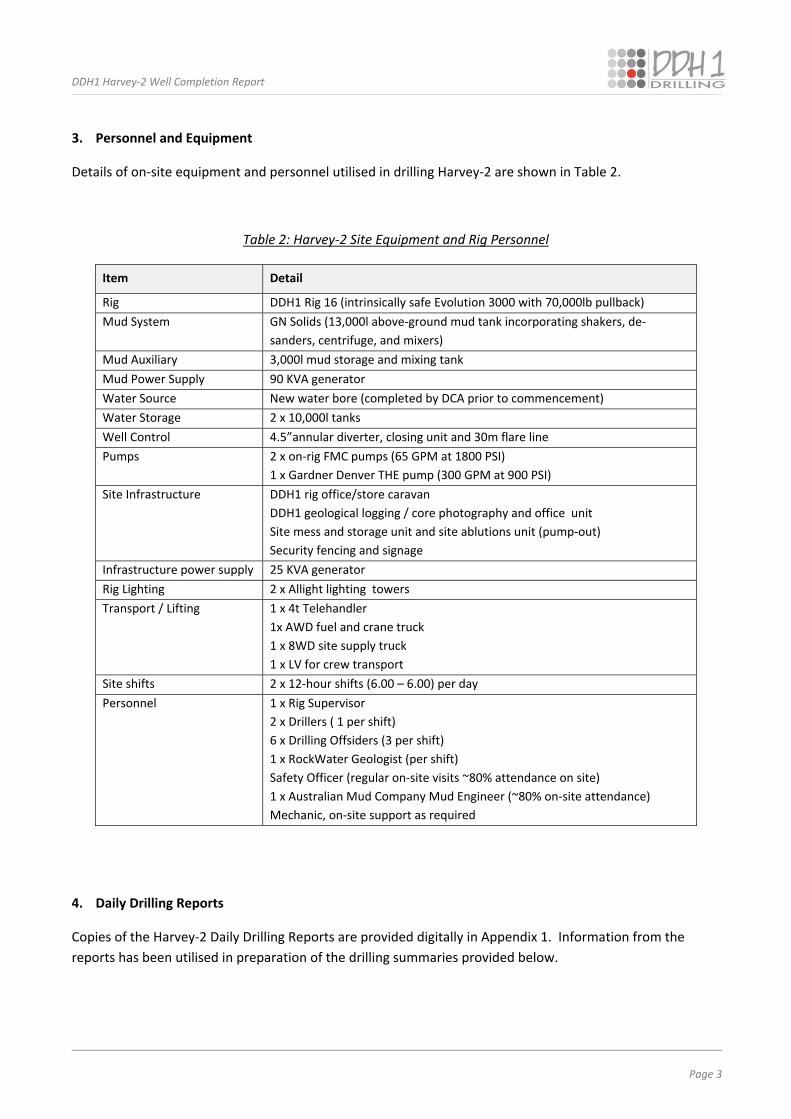
3. Personnel and Equipment
Details of on‐site equipment and personnel utilised in drilling Harvey‐2 are shown in Table 2.
Table 2: Harvey‐2 Site Equipment and Rig Personnel
Item Detail
Rig DDH1 Rig 16 (intrinsically safe Evolution 3000 with 70,000lb pullback)
Mud System GN Solids (13,000l above‐ground mud tank incorporating shakers, de‐
sanders, centrifuge, and mixers)
Mud Auxiliary 3,000l mud storage and mixing tank
Mud Power Supply 90 KVA generator
Water Source New water bore (completed by DCA prior to commencement)
Water Storage 2 x 10,000l tanks
Well Control 4.5”annular diverter, closing unit and 30m flare line
Pumps 2 x on‐rig FMC pumps (65 GPM at 1800 PSI)
1 x Gardner Denver THE pump (300 GPM at 900 PSI)
Site Infrastructure DDH1 rig office/store caravan
DDH1 geological logging / core photography and office unit
Site mess and storage unit and site ablutions unit (pump‐out)
Security fencing and signage
Infrastructure power supply 25 KVA generator
Rig Lighting 2 x Allight lighting towers
Transport / Lifting 1 x 4t Telehandler
1x AWD fuel and crane truck
1 x 8WD site supply truck
1 x LV for crew transport
Site shifts 2 x 12‐hour shifts (6.00 – 6.00) per day
Personnel 1 x Rig Supervisor
2 x Drillers ( 1 per shift)
6 x Drilling Offsiders (3 per shift)
1 x RockWater Geologist (per shift)
Safety Officer (regular on‐site visits ~80% attendance on site)
1 x Australian Mud Company Mud Engineer (~80% on‐site attendance)
Mechanic, on‐site support as required
4. Daily Drilling Reports
Copies of the Harvey‐2 Daily Drilling Reports are provided digitally in Appendix 1. Information from the
reports has been utilised in preparation of the drilling summaries provided below.
DDH1 Harvey‐2 Well Completion Report
Page 4
5. Summary of Pre‐Spud and Rig‐Up Procedures (December 2 – December 5, 2014)
Drill pad preparation and access works were completed under the supervision of KD1 Pty Ltd (KD1) in
November, 2014 and DDH1’s drilling crew, rig and ancillary equipment arrived at the site on December 2. All
crew underwent site inductions and participated in a review of safe‐work procedures for rig‐up operations
which were completed on December 5. Harvey‐2 drilling operations commenced the following morning
after a Pre‐Spud meeting involving all site personnel.
6. Summary of Drilling Operations (December 6 – March 4, 2015)
Conductor and Surface Casing (Tricone & blade, 12 1/8’’ hole, 0 to 65m):
The Harvey‐2 conductor hole was drilled with a 14” blade bit and bentonite base mud to a depth of 7.4m and
steel 12 ¼” ID conductor casing was subsequently installed. A slight flow of fresh water emanated from the
conductor drill hole, however this stopped when the conductor casing was cemented back to surface.
Dual‐shift 24hr operations commenced the next day and the hole was progressed from 7.4m to 24m using a
12 ⅛” roller bit. During this interval it became apparent that at the circulation volumes required for such a
large‐diameter hole, the Solids Control Unit (SCU) could not maintain adequate cleaning of solids. To
remedy this situation, the hole was subsequently progressed to the planned surface casing depth of 65m
using an 8 ½” bit and reamed to 12 ⅛”. A wiper run was then completed in preparation for running casing.
During casing operations, 9 ⅝” buttress casing with float shoe and centralizers was run to 64m and no
backfill was encountered. Cementing operations utilised 2000ltrs of 15ppg cement slurry pumped with a
displacement plug until cement slurry returns were observed at the surface.
Whilst waiting for the cement to cure, it was noted that the cement slumped and that fresh water started to
flow to surface from the annulus between the 9 ⅝” and 12 ¼”ID conductor casing. A top‐up cementing job
(500ltrs @ 15.6ppg) initially stopped the water. However after some time, additional slumping was
observed and water again flowed to the surface (albeit at a much reduced rate relative to the initial egress).
A second top‐up cement job (500ltrs @ 17.2ppg) was successfully completed with no slumping and the flow
was completely contained. Ongoing monitoring for the drilling duration of Harvey‐2 failed to find any
evidence of renewed groundwater seepage.
Intermediate Casing (Mud rotary, 8 ½” hole, 65 to 206.5m):
The 8 ½” hole continued to plan and the intermediate casing depth of 206.5m was reached on 11/12/2014.
During the wiper run, 2.5m of backfill was encountered and the decision was made to drill a further 1m in
order to accommodate the backfill and allow the casing to be landed at the correct height for the well
control annular preventer.
The 7” BTC casing was run cleanly to depth and 3500ltrs of cement (@ 15ppg) was pumped and displaced
with positive returns observed at surface. The displacement plug was bumped to 800psi and held for 30
minutes. No top‐up cement was necessary for the 7” BTC intermediate casing job.
DDH1 Harvey‐2 Well Completion Report
Page 5
Single shift operations were subsequently implemented until 14/12/2014 when the remaining crew
departed site for the Christmas break. The DDH1 crew returned to site 05/01/2015 and double shift
operations re‐commenced the following day.
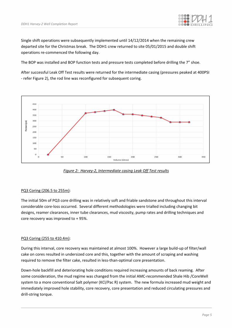
The BOP was installed and BOP function tests and pressure tests completed before drilling the 7” shoe.
After successful Leak Off Test results were returned for the intermediate casing (pressures peaked at 400PSI
‐ refer Figure 2), the rod line was reconfigured for subsequent coring.
Figure 2: Harvey‐2, Intermediate casing Leak Off Test results
PQ3 Coring (206.5 to 255m):
The initial 50m of PQ3 core drilling was in relatively soft and friable sandstone and throughout this interval
considerable core‐loss occurred. Several different methodologies were trialled including changing bit
designs, reamer clearances, inner tube clearances, mud viscosity, pump rates and drilling techniques and
core recovery was improved to + 95%.
PQ3 Coring (255 to 410.4m):
During this interval, core recovery was maintained at almost 100%. However a large build‐up of filter/wall
cake on cores resulted in undersized core and this, together with the amount of scraping and washing
required to remove the filter cake, resulted in less‐than‐optimal core presentation.
Down‐hole backfill and deteriorating hole conditions required increasing amounts of back reaming. After
some consideration, the mud regime was changed from the initial AMC‐recommended Shale Hib /CoreWell
system to a more conventional Salt polymer (KCl/Pac R) system. The new formula increased mud weight and
immediately improved hole stability, core recovery, core presentation and reduced circulating pressures and
drill‐string torque.
DDH1 Harvey‐2 Well Completion Report
Page 6
PQ3 Coring (410.4 to 603.4m):
Excellent core recovery was maintained throughout this section and operations continued to plan. Four bit
changes were completed and drill‐pipe tripped at 603.4m to run a Carbonaro surface‐set step bit.
PQ3 Coring (603.4 to 666.4m):
At 615.1m, a pressurised shear was intersected. The hole was stabilised and progressed to 618m before
pumping 180ltr of 14.5ppg cement through the core barrel to successfully stabilise this zone. At 666.4m the
3m core barrel used to drill out the cement was replaced with a 6m core barrel.
PQ3 Coring (666.4 to 922m):
During this interval, coring was maintained at a reasonably steady rate. However lost circulation material
(LCM) was required to seal the coarser sandstone horizons that were regularly encountered at the interface
of sandstone and mudstone layers. Increased mud weights (to 9.8‐10ppg) were found to improve hole
stability and minimise the amount of reaming required.
PQ3 Coring (922 to 1233.4m):
No significant issues were encountered in the interval 922 to 1233.4m.
PQ3 Coring (1233.4 to 1233.7m):
After completing a bit change at 1233.4m, difficulties were encountered whilst returning to bottom.
Numerous zones (especially at 1032m, 1062.3m, 1138.2m and 1168.3 to 1182.3m) had become unstable and
required significant amounts of reaming to allow the string to pass.
Once the barrel was washed to bottom and circulated prior to drilling, the core run was recommenced.
However, coring was stopped 300mm into the run due to indications that the inner tube was blocked with
backfill. The rods were retracted 6.4m off bottom and the inner‐tube was pulled, however, when the head
was reconnected the drill pipe was stuck and circulation was limited. The drill‐pipe and core barrel became
stuck 6.4m off bottom at 1227m.
On 13/02/2015, fishing operations commenced to free the drill‐pipe however the crew were unable to work
the rods free. An HQ rod line was delivered to site to run inside the PHD drill‐string and the PQ inner tube
was retrieved by drilling into it with the HQ core barrel. An additional attempt to recover the entire stuck
rod line was made using a specialist oil‐field actuating jar (recommended and supervised by Weatherfords),
but this proved unsuccessful.
DDH1 Harvey‐2 Well Completion Report
Page 7
HQ Coring (1233.7 to 1350.2m, TD):
On 16/02/2015, drilling re‐commenced using a smaller HQ core barrel and HRQ drill‐string (with the stuck
PHD drill‐string effectively acting as casing for the deteriorated wall rock sections within the hole).
Coring progressed to 1317.8m, at which point the HQ assembly became stuck after retrieving an inner tube
of core from the Wonnerup Formation. Circulation was maintained and the likely cause was assessed as
differential sticking. After extended flushing, the drill‐pipe was freed by the use of dual pull using both the
top drive and the main winch in unison.
Drilling was completed on22/02/2015 when Harvey‐2 reached the planned total depth of 1350.2m
7. Wireline Logging
Wireline logging operations were undertaken by Haliburton on 22/2/2015 and 23/2/2015. The entire hole to
1350m (including the HQ section) was logged successfully.
8. PQ Rod Line Retrieval
On 23/02/2015, cutting operations commenced to retrieve the stuck PHD string. Six cuts were undertaken
as follows:‐
Cut 1, 1180m: Unsuccessful in retrieving any drill pipe.
Cut 2, 1130m: Although apparently successful (circulation was observed at surface indicating that
the casing had been cut), it was still impossible to move the PHD drill pipe (indicating differential
sticking further up hole). In an attempt to release the differentially stuck pipe, a hole sweep of Well
Clean, Aus‐Det, Penetrol and Potassium Chloride was undertaken. The sweep effect was positive
and 1 metre of stretch was gained, however the pipe still remained immovable.
Cut 3, 900m: No improvement or further movement of stuck pipe.
Cut 4, 720m: No improvement or further movement of stuck pipe.
Cut 5, 600m: The pipe was freed and was able to be lifted. Freshly weighted mud was circulated
and the casing sat back on the cut casing to enable abandonment process to take place. However,
after installing the bottom hole (abandonment) cement and connecting back up to the cut, the PHD
casing was unable to be moved. It was apparent that once full circulation had been restored, the
formation had rapidly deteriorated and the casing had become differentially stuck again.
Cut 6, 550m: After successful freeing up of the drill pipe, a CWBP Van Ruth plug was placed in the
hole at 550m and covered with a 20mtr 14ppg cement plug. The remaining 550m of the PHD string
was retrieved on 2/3/2015 using the top drive in conjunction with the main winch.
DDH1 Harvey‐2 Well Completion Report
Page 8
9. Abandonment
Completion casing (3 ½” BTC) was run with no obstruction to 410m. However, at this point the casing
became tight in the hole and was unable to be advanced past 414.6m. The casing was grouted (with grout
returns observed at surface) and the hole was finally capped and abandoned on 5/3/2015.
10. Mud Program
As mentioned previously, AMC was contracted to provide product and mud engineering services for the
entire Harvey drilling program including:
Pre‐drill test work on historic samples from drill hole Harvey‐1 with a view to designing and costing
the most appropriate drilling fluids for the current program,
Ongoing monitoring and technical support during drilling activities at Harvey‐2, ‐3 and ‐4,
A review of the effectiveness of the various mud programs with the aim of informing future drilling
in the Harvey sequestration project.
AMC’s Harvey‐2 Drilling Fluid Summary Report is included herein as Appendix 2 and summary comments
drawn from it and from DDH1’s experience are listed below:
At Harvey‐2, the extended drilling timetable added considerably to drilling fluid costs.
Fluid shear stress and polymer break down is proportional to total circulation time. The extended
drilling timetable required additional product to ensure fluid properties were maintained to
specifications.
The initial program recommended a CoreWell/Shale Hib base which proved less effective than
indicated by pre‐program testing. The CoreWell/Shale Hib system was replaced with a KCl/PAC R
system at 409m.
The change to KCl was made to offset increasing amounts of backfill during rod pulls, intermittent
dropping of core and increasingly poor core presentation (which had become dirty and difficult to
remove from the splits). After changing to KCl, the backfill reduced and the core became cleaner.
Core recovery was similar with both fluid types. The addition of KCl assisted with sidewall stability
via hydrostatic pressure.
The initial KCl/PAC R system was run at 10% KCl (~50,000 ppm chlorides) with a mud weight SG 1.1
(9.2 – 9.3 lb/gal).
Chloride concentrations varied 45,000 to 70,000ppm on average. Variations were partly due to
individual testing techniques and the timing of sample collection.
DDH1 Harvey‐2 Well Completion Report
Page 9
Subsequently the mud weight was increased and kept constant at around SG 1.13 (9.4 – 9.5 lb/gal).
At approximately 1100 m, the PQ pipes became stuck (14/2) and the hole began to flow which
diluted the system.
To maintain hole stability, mud weight was increased to SG 1.22 (10.2 lb/gal) with chloride content
of 110,000 – 127,000ppm and was kept consistent to the end of the hole at 1350.2m.
11. Bit Record
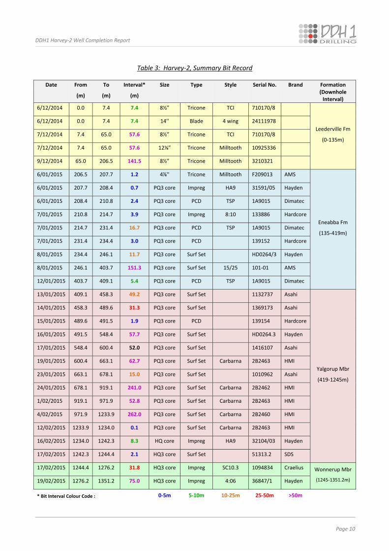
A summary of bit usage throughout the hole is provided in Table 3. Bit changes were particularly frequent at
the start of the coring program when attempts were made to determine the optimal bits for drilling progress
and for core recovery. Bit changes were also frequent when difficulties were encountered trying to cut
particularly hard / abrasive formations and/or when formations were varying rapidly. Maximum cutting
performance and core recovery was achieved using surface‐set internal discharge step bits with large
protruding diamonds.
12. Community Engagement
In consultation with clients, DDH1 seeks to positively engage with community stakeholders on all drilling
projects. Working collaboratively with DMP and KD1 staff at Harvey‐2, DDH1 sought to:‐
establish and maintain good relations with local land‐owners,
locally source accommodation and messing (rather than bringing the company’s camp onto site),
purchase most non‐drilling consumables from local suppliers,
engage local tradespeople and services whenever possible (e.g. electrical, mechanical, engineering,
cementing, some transport, etc.),
facilitate safe rig site access for client‐hosted Open Days and Site Visits,
minimise traffic, dust, noise, stock disturbance, etc., both at the rig site and on local roads,
address any concerns promptly and respectfully,
maintain a clean, tidy, secure and safe work site,
minimise environmental disturbance at all times.
DDH1 Harvey‐2 Well Completion Report
Page 10
Table 3: Harvey‐2, Summary Bit Record
Date From To Interval* Size Type Style Serial No. Brand Formation
(m) (m) (m) (Downhole Interval)
6/12/2014 0.0 7.4 7.4 8½” Tricone TCI 710170/8
Leederville Fm
(0‐135m)
6/12/2014 0.0 7.4 7.4 14'' Blade 4 wing 24111978
7/12/2014 7.4 65.0 57.6 8½” Tricone TCI 710170/8
7/12/2014 7.4 65.0 57.6 12⅛” Tricone Milltooth 10925336
9/12/2014 65.0 206.5 141.5 8½” Tricone Milltooth 3210321
6/01/2015 206.5 207.7 1.2 4⅞'' Tricone Milltooth F209013 AMS
Eneabba Fm
(135‐419m)
6/01/2015 207.7 208.4 0.7 PQ3 core Impreg HA9 31591/05 Hayden
6/01/2015 208.4 210.8 2.4 PQ3 core PCD TSP 1A9015 Dimatec
7/01/2015 210.8 214.7 3.9 PQ3 core Impreg 8:10 133886 Hardcore
7/01/2015 214.7 231.4 16.7 PQ3 core PCD TSP 1A9015 Dimatec
7/01/2015 231.4 234.4 3.0 PQ3 core PCD 139152 Hardcore
8/01/2015 234.4 246.1 11.7 PQ3 core Surf Set HD0264/3 Hayden
8/01/2015 246.1 403.7 151.3 PQ3 core Surf Set 15/25 101‐01 AMS
12/01/2015 403.7 409.1 5.4 PQ3 core PCD TSP 1A9015 Dimatec
13/01/2015 409.1 458.3 49.2 PQ3 core Surf Set 1132737 Asahi
Yalgorup Mbr
(419‐1245m)
14/01/2015 458.3 489.6 31.3 PQ3 core Surf Set 1369173 Asahi
15/01/2015 489.6 491.5 1.9 PQ3 core PCD 139154 Hardcore
16/01/2015 491.5 548.4 57.7 PQ3 core Surf Set HD0264.3 Hayden
17/01/2015 548.4 600.4 52.0 PQ3 core Surf Set 1416107 Asahi
19/01/2015 600.4 663.1 62.7 PQ3 core Surf Set Carbarna 2B2463 HMI
23/01/2015 663.1 678.1 15.0 PQ3 core Surf Set 1010962 Asahi
24/01/2015 678.1 919.1 241.0 PQ3 core Surf Set Carbarna 2B2462 HMI
1/02/2015 919.1 971.9 52.8 PQ3 core Surf Set Carbarna 2B2463 HMI
4/02/2015 971.9 1233.9 262.0 PQ3 core Surf Set Carbarna 2B2460 HMI
12/02/2015 1233.9 1234.0 0.1 PQ3 core Surf Set Carbarna 2B2463 HMI
16/02/2015 1234.0 1242.3 8.3 HQ core Impreg HA9 32104/03 Hayden
17/02/2015 1242.3 1244.4 2.1 HQ3 core Surf Set 51313.2 SDS
17/02/2015 1244.4 1276.2 31.8 HQ3 core Impreg SC10.3 1094834 Craelius Wonnerup Mbr
(1245‐1351.2m) 19/02/2015 1276.2 1351.2 75.0 HQ3 core Impreg 4:06 36847/1 Hayden
* Bit Interval Colour Code : 0‐5m 5‐10m 10‐25m 25‐50m >50m
DDH1 Harvey‐2 Well Completion Report
Page 11
13. Discussion of Outcomes
To date, most deep drill holes in the variably consolidated sedimentary rocks of the Perth Basin have been
completed for oil and gas targets using large‐scale oil‐field rigs and rotary mud drilling techniques with only
limited core runs in zones of specific interest. The first hole in the South West Hub CCS Project, Harvey‐1,
was drilled in this manner (Millar and Reeve, 2014).
The requirement for continuous, large‐diameter core to depth in Harvey‐2, as an integral part of ongoing
research in the South West Hub CCS, provided an innovative opportunity for the application of continuous
wireline coring drilling techniques using a heavy‐duty slim‐hole rig of the type more conventionally used in
the mineral exploration sector. DDH1’s Rig 16, an intrinsically safe Evolution 3000 with upgraded pull back
capacity, in tandem with the GN solids mud system were well suited to this task.
Impressions gained from pre‐start inspection of the restricted cored intervals from Harvey‐1 formed an
integral part of the Harvey‐2 well design and drilling plan. However, in practise, lithologies encountered in
the Wonnerup and Yalgorup Formations in Harvey‐2 were harder and more abrasive than expected. It is not
known whether the differences are related to inherent variability in the sedimentary pile or whether they
are related to increased secondary silicification – perhaps due to increased faulting /fracturing the vicinity of
Harvey‐2. Locally intense ferrugunisation effects were also noted throughout much of the core and may
have contributed to variabilities in down‐hole competency.
Other formation features (essentially confined to the Yalgorup and Wonnerup Members) that presented
some drilling issues included:
at the local scale, porous and permeable very coarse to gritty sandstone beds (requiring sealing with
LCM) in contact with significantly finer‐grained horizons (with potential for swelling clays),
more friable horizons with potential for wash‐out and caving,
at the larger scale, the transition from the Yalgorup to Wonnerup Members (with potential for
differential sticking largely related to differential clay components).
Formation variability combined with very hard and abrasive characteristics meant that, relative to the
original Harvey‐2 hole plan, the rate of progress (ROP) was (unavoidably) slower than anticipated (Figure 1)
and that more‐than‐expected bit changes and rod‐line trip‐outs were required. Extended drilling times and
increased down‐hole mechanical activity result in lengthened exposure times to drilling fluids and annular
pressures which, for time‐sensitive formations, can lead to significant deterioration.
In Harvey‐2 critical attention to adequately inhibited and correctly weighted drilling mud was largely
successful in stabilising the hole. However, after the delays incurred with the irretrievably stuck rod line at
1227m (close to the critical Wonnerup to the Yalgorup Formation interface) and with multiple pipe‐cutting
attempts, it was obvious that the entire cored section was breaking down and very prone to differential
sticking.
DDH1 Harvey‐2 Well Completion Report
Page 12
Features inherent in wireline coring equipment (e.g., small annulus and a high wall contact area) increase
differential sticking potential in susceptible lithologies and once a wireline rod string becomes stuck it is
more difficult to free than a conventional drill string. It is unlikely that the formations encountered in
Harvey‐2 would have posed similar sticking issues if drilled using conventional rotary‐drill techniques. In the
latter there is no need for stationary drill‐pipe or swabbing whilst retrieving wireline core and increased
annular clearances and penetration rates reduce the contact and time‐exposure of potentially problematical
rock types.
Whilst it was disappointing that the entire hole could not be completed in PQ3 core, the inherent flexibility
of the wireline coring system and the ability to reduce to HQ core still enabled full core coverage of the rock
record in Harvey‐2. Destructive rotary‐mud drilling techniques could obviously not have achieved this
outcome.
Notwithstanding the challenges encountered in drilling Harvey‐2, successful completion of the well to target
depth endorses slimhole wireline continuous coring as a viable drilling technique in the young and variably‐
consolidated sediments of the Perth Basin. Harvey‐2 demonstrated that the enhanced geological and
geotechnical information that only core can provide is achievable in these types of sequences.
The pro‐active and collaborative approach by all parties involved in Harvey‐2 contributed not only to the
technical success of the program but also to the maintenance of good community relations throughout
drilling program.
14. References
Millar, AS and Reeve, J, 2014. GSWA Harvey 1 Well completion and preliminary interpretation report,
southern Perth Basin, GSWA Record 2014/12.
DDH1 Harvey‐2 Well Completion Report
APPENDICES
APPENDIX 1: Harvey‐2 DDH1 Daily Drilling Reports (provided as digital copy only)

DDH1 Harvey‐2 Well Completion Report
APPENDICES
APPENDIX 2: Australian Mud Company Harvey‐2 Drilling Fluid Summary Report
Harvey‐2 Well Completion Report Appendix 2: Australian Mud Company, Harvey‐2 Drilling Fluid Summary Report
Harvey‐2
Drilling Fluid Summary Report
AMC Minerals
Western Australia
October 2015
216 Balcatta Road, Balcatta WA, Australia 6021
PO Box 1141, Osborne Park WA, Australia 6916
Tel: +61 (0) 8 9445 4000 Fax: +61 (0) 8 9445 4040 [email protected] www.amcmud.com ABN 56 009 283 416
Harvey‐2 Well Completion Report Appendix 2: Australian Mud Company, Harvey‐2 Drilling Fluid Summary Report
Appendix 2: Page i
TABLE OF CONTENTS
Item Page No
1. Introduction 1
2. General Design Principles for the Drilling Fluids Program 1
3. Harvey‐1, Data Review and Geotechnical Testwork 2
4. “Make‐Up” Water Analysis 3
5. Drilling Fluid Proposal 3
6. Mud Program Operations 4
6.1 Pre‐Collar Section (0‐208m) 4
6.2 Cored Section (208‐409m) 5
6.3 Cored Section (409‐1350m) 6
7. Materials Consumption and Cost Analysis of the Harvey‐2 Drilling Fluid Program 8
8. Conclusions and Recommendations 10
9. References 10
LIST OF TABLES
Table Page No
1 Sample intervals and fluid combinations selected for Phase 1 and Phase 2 test work on historic Harvey‐1 cuttings and core 2
2 Fluid Properties for Harvey‐2 Pre‐Collar Section, 0‐208m 4 3 Summary of Drilling Activity Harvey‐2 PQ Core Interval, 208‐409m 5
4 Fluid Properties for Harvey‐2 PQ Core Interval, 208‐409m 6
5 Revised Mud System Fluid Properties for Harvey‐2 Core Interval, 409‐ 1350.2m 7
6 Fluid Additions whilst Drilling with the Revised Mud System
7 Harvey‐2, Programmed vs Actual Materials Consumption and Costs 8
8 Harvey‐2, Summary of Cost Variance for the Original (Un‐Weighted) and
Revised (Weighted) Mud Programs 9
ATTACHMENTS
Pre‐Drill Test Work (Historic Samples from GSWA Harvey‐1)
Attachment A: Immersion Testing Program 1, September, 2014
Attachment B: Immersion Testing Program 2, November, 2014
Harvey‐2 Well Completion Report Appendix 2: Australian Mud Company, Harvey‐2 Drilling Fluid Summary Report
Appendix 2 Page 1
1. Introduction
In September, 2014, the Australian Mud Company (AMC) was engaged by DDH1 Drilling to provide
technical support and ongoing mud supplies for deep drill holes Harvey‐2, ‐3 and ‐4 in the South West
Hub Carbon Capture and Storage (CCS) Project.
AMC’s brief was to provide:‐
Pre‐drill test work on historic samples from drill hole Harvey‐1 with a view to designing and
costing the most appropriate mud program(s) for Harvey 2, 3 and 4,
Ongoing monitoring and technical support for holes Harvey‐2 and ‐3 (to be cored by DDH1
Drilling) and Harvey‐4 (to be rotary drilled by Drilling Contractors Australia with limited coring
intervals),
Mud product supply,
A review of the effectiveness of the various mud programs with the aim of informing future
drilling in the Harvey sequestration project.
This report describes AMC’s input into those programs. 2. General Design Principles for the Drilling Fluids Program In designing the Harvey Project mud programs, AMC considered the following issues:
Geotechnical characteristics of likely down‐hole formations including formation integrity,
Choice of the most effective fluid(s) to stabilise down‐hole conditions with appropriate
parameters to address encapsulation, inhibition and filtration control,
Analysis of on‐site “make‐up” water,
Ease of use of the selected fluid(s),
The need to minimise costs (without adversely impacting fluid effectiveness),
The need to minimise any potential environmental impacts of the fluids used,
Ease of disposal of mud products at the completion of the program.
Harvey‐2 Well Completion Report Appendix 2: Australian Mud Company, Harvey‐2 Drilling Fluid Summary Report
Appendix 2 Page 2
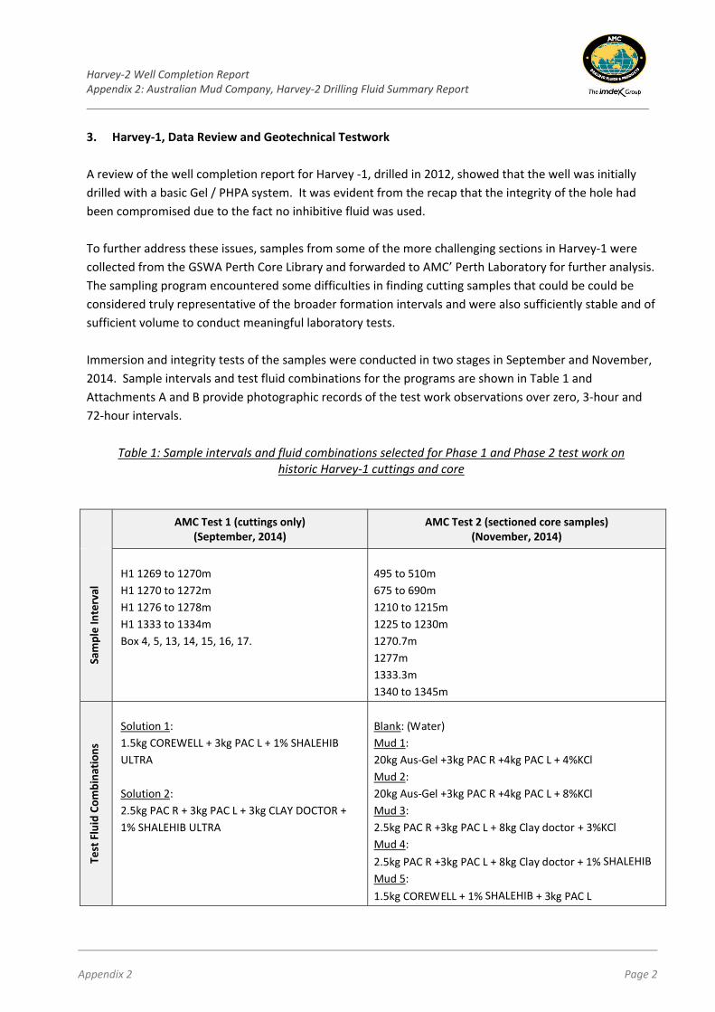
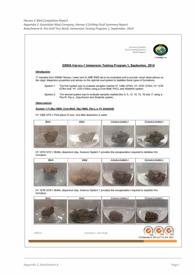
3. Harvey‐1, Data Review and Geotechnical Testwork
A review of the well completion report for Harvey ‐1, drilled in 2012, showed that the well was initially
drilled with a basic Gel / PHPA system. It was evident from the recap that the integrity of the hole had
been compromised due to the fact no inhibitive fluid was used.
To further address these issues, samples from some of the more challenging sections in Harvey‐1 were
collected from the GSWA Perth Core Library and forwarded to AMC’ Perth Laboratory for further analysis.
The sampling program encountered some difficulties in finding cutting samples that could be could be
considered truly representative of the broader formation intervals and were also sufficiently stable and of
sufficient volume to conduct meaningful laboratory tests.
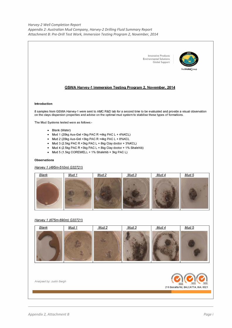
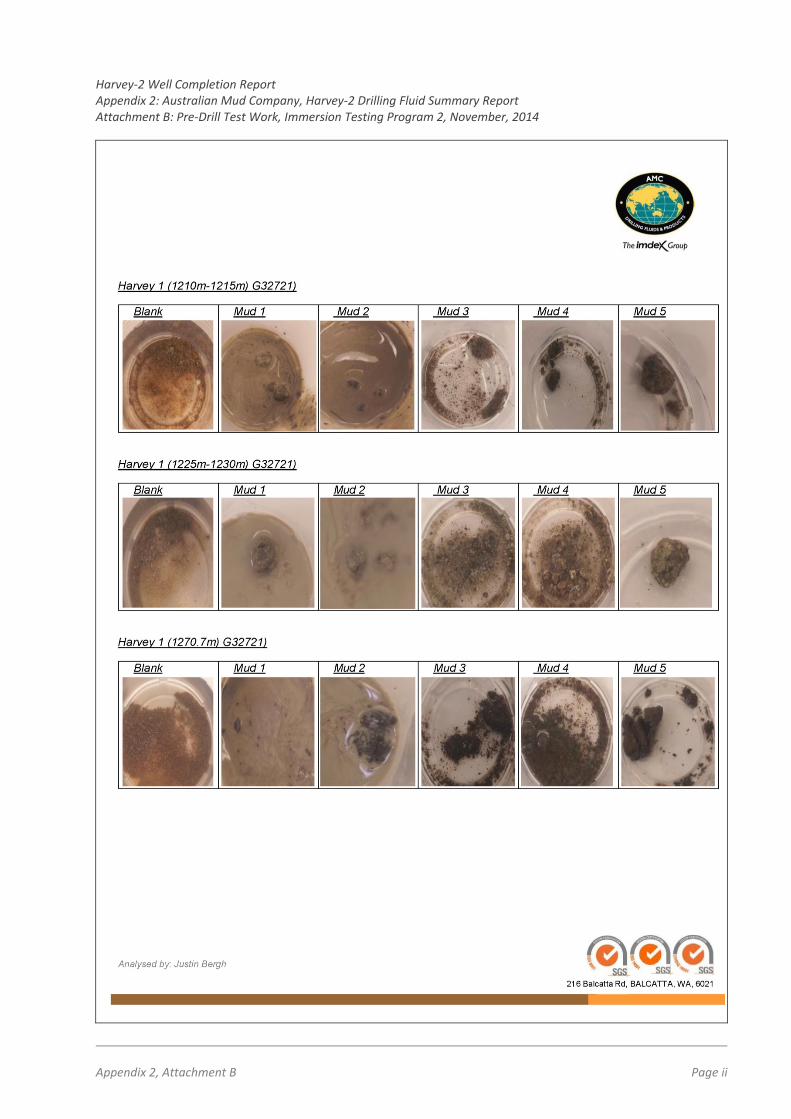
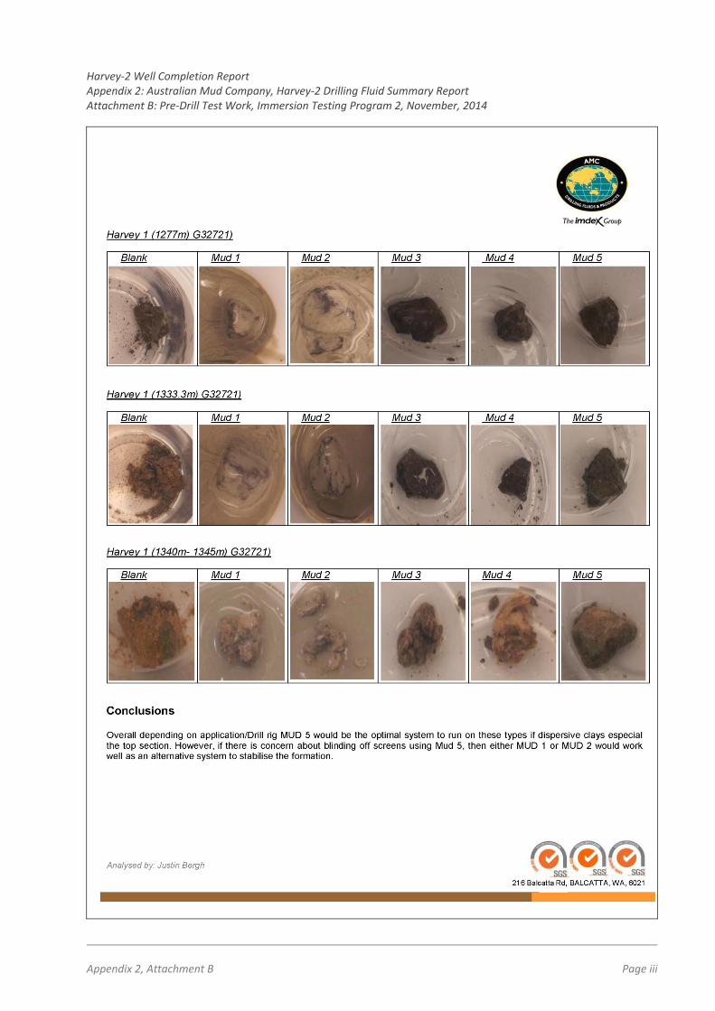
Immersion and integrity tests of the samples were conducted in two stages in September and November,
2014. Sample intervals and test fluid combinations for the programs are shown in Table 1 and
Attachments A and B provide photographic records of the test work observations over zero, 3‐hour and
72‐hour intervals.
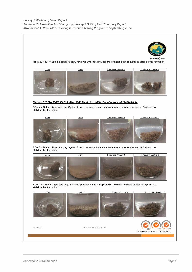
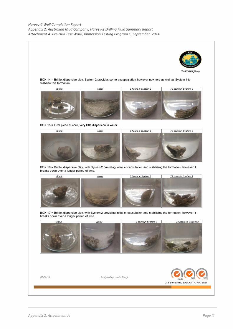
Table 1: Sample intervals and fluid combinations selected for Phase 1 and Phase 2 test work on historic Harvey‐1 cuttings and core
AMC Test 1 (cuttings only) (September, 2014)
AMC Test 2 (sectioned core samples) (November, 2014)
Sample In
terval
H1 1269 to 1270m
H1 1270 to 1272m
H1 1276 to 1278m
H1 1333 to 1334m
Box 4, 5, 13, 14, 15, 16, 17.
495 to 510m
675 to 690m
1210 to 1215m
1225 to 1230m
1270.7m
1277m
1333.3m
1340 to 1345m
Test Fluid Combinations
Solution 1:
1.5kg COREWELL + 3kg PAC L + 1% SHALEHIB
ULTRA
Solution 2:
2.5kg PAC R + 3kg PAC L + 3kg CLAY DOCTOR +
1% SHALEHIB ULTRA
Blank: (Water)
Mud 1:
20kg Aus‐Gel +3kg PAC R +4kg PAC L + 4%KCl
Mud 2:
20kg Aus‐Gel +3kg PAC R +4kg PAC L + 8%KCl
Mud 3:
2.5kg PAC R +3kg PAC L + 8kg Clay doctor + 3%KCl
Mud 4:
2.5kg PAC R +3kg PAC L + 8kg Clay doctor + 1% SHALEHIB
Mud 5:
1.5kg COREWELL + 1% SHALEHIB + 3kg PAC L
Harvey‐2 Well Completion Report Appendix 2: Australian Mud Company, Harvey‐2 Drilling Fluid Summary Report
Appendix 2 Page 3
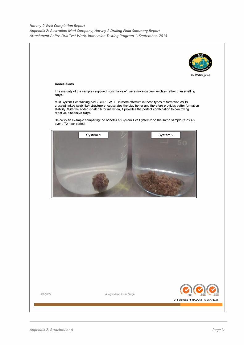
Results from both phases of test work (refer Attachments A and B) showed that the clays encountered in
Harvey‐1 were more dispersive than swelling in nature. The best containment results came from AMC’s
CORE‐WELL based system, which is a premium encapsulating agent.
4. “Make‐Up” Water Analysis In addition to formation integrity testing, the “make‐up” water to be used in the mud program from the
on‐site, purpose‐drilled water bore was analysed with results as follows:
pH 6 ‐ 7,
Total Hardness: 250 mg/l,
Chlorides: 1900 mg/l.
5. Drilling Fluid Proposal
AMC’s final drilling fluid proposal envisaged a two component program as follows:
For the rotary pre‐collar section ‐ a conventional gel/polymer mix was recommended to give the
best hole cleaning characteristics and to allow good filtrate control as well as hole stabilisation
From the start of coring, utilisation of the CORE‐WELL based clay‐inhibiting system were
recommended with KCl included as an ancillary item (at lower properties that used in Harvey 1).
The rationale was that the proactive approach to protecting the formation would reduce the
percentage of KCl required to control the formation. A contingency was also allowed in the mud
program for adding a weighting agent (Sodium Chloride) to the system to obtain a mud weight
similar to that of Harvey‐1 if needed.
Mud 5 from the second geotechnical test program (i.e., 1.5kg COREWELL + 1% SHALEHIB + 3kg PAC‐L) was selected as the drilling fluid of choice for the cored section of the well.
In addition to the system’s superior encapsulating properties, it also had potential environmental benefits
of limiting of chloride addition to ground‐water. The lower chloride content would also result in greater ease and reduced costs of disposal at conventional refuse facilities. Although the COREWELL (powder), SHALEHIB (fluid) and PAC‐L (powder) mud system was a three‐part
mix, reduced product volumes and reduced corrosive character were considered advantageous and less onerous to mix than to chloride‐based system. After completing Harvey‐2, the fluid system would be reassessed and, if necessary, revised for the
Harvey‐3 well.
Harvey‐2 Well Completion Report Appendix 2: Australian Mud Company, Harvey‐2 Drilling Fluid Summary Report
Appendix 2 Page 4
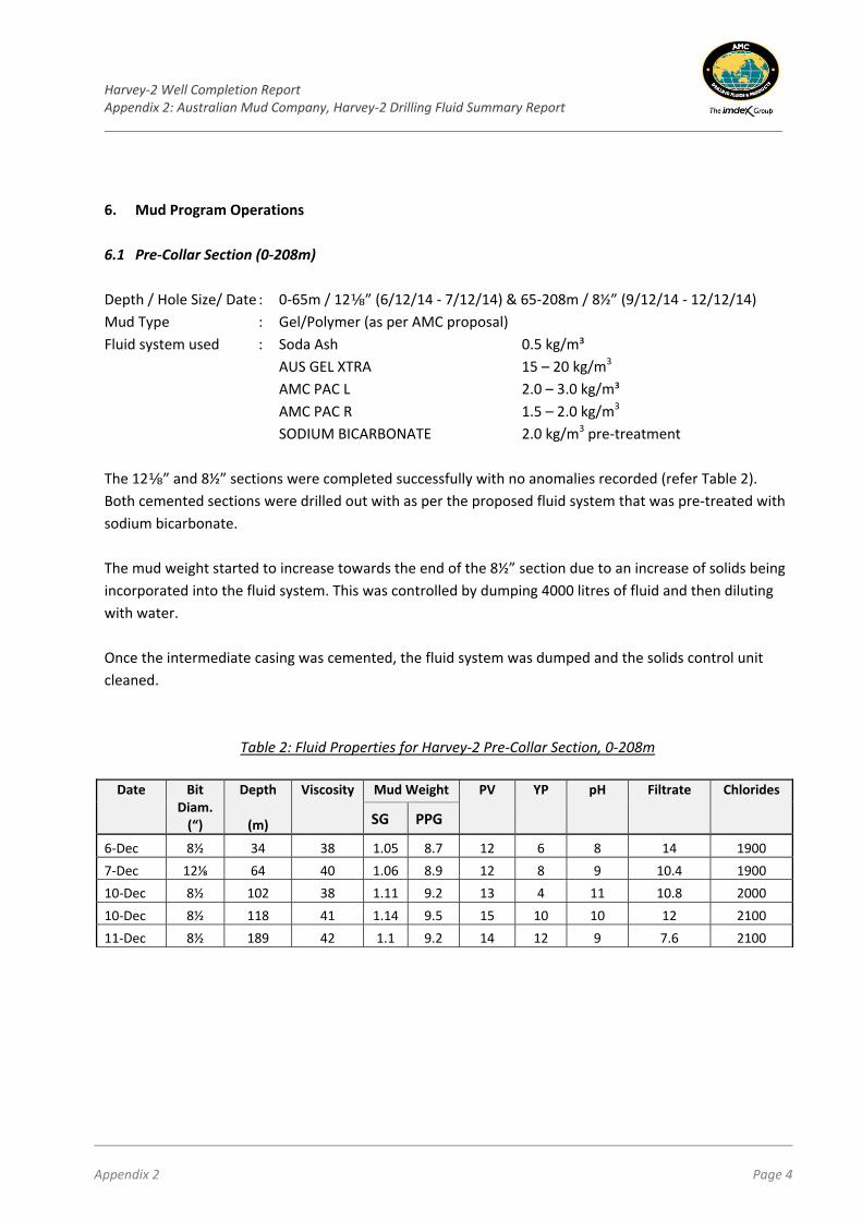
6. Mud Program Operations
6.1 Pre‐Collar Section (0‐208m)
Depth / Hole Size/ Date : 0‐65m / 12⅛” (6/12/14 ‐ 7/12/14) & 65‐208m / 8½” (9/12/14 ‐ 12/12/14)
Mud Type : Gel/Polymer (as per AMC proposal)
Fluid system used : Soda Ash 0.5 kg/m³
AUS GEL XTRA 15 – 20 kg/m3
AMC PAC L 2.0 – 3.0 kg/m³
AMC PAC R 1.5 – 2.0 kg/m3
SODIUM BICARBONATE 2.0 kg/m3 pre‐treatment
The 12⅛” and 8½” sections were completed successfully with no anomalies recorded (refer Table 2).
Both cemented sections were drilled out with as per the proposed fluid system that was pre‐treated with
sodium bicarbonate.
The mud weight started to increase towards the end of the 8½” section due to an increase of solids being
incorporated into the fluid system. This was controlled by dumping 4000 litres of fluid and then diluting
with water.
Once the intermediate casing was cemented, the fluid system was dumped and the solids control unit
cleaned.
Table 2: Fluid Properties for Harvey‐2 Pre‐Collar Section, 0‐208m
Date Bit Diam. (“)
Depth
(m)
Viscosity Mud Weight PV YP pH Filtrate Chlorides
SG PPG
6‐Dec 8½ 34 38 1.05 8.7 12 6 8 14 1900
7‐Dec 12⅛ 64 40 1.06 8.9 12 8 9 10.4 1900
10‐Dec 8½ 102 38 1.11 9.2 13 4 11 10.8 2000
10‐Dec 8½ 118 41 1.14 9.5 15 10 10 12 2100
11‐Dec 8½ 189 42 1.1 9.2 14 12 9 7.6 2100
Harvey‐2 Well Completion Report Appendix 2: Australian Mud Company, Harvey‐2 Drilling Fluid Summary Report
Appendix 2 Page 5
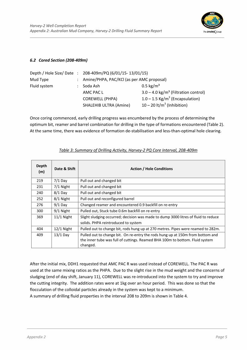
6.2 Cored Section (208‐409m)
Depth / Hole Size/ Date : 208‐409m/PQ (6/01/15‐ 13/01/15)
Mud Type : Amine/PHPA, PAC/KCl (as per AMC proposal)
Fluid system : Soda Ash 0.5 kg/m³
AMC PAC L 3.0 – 4.0 kg/m³ (Filtration control)
COREWELL (PHPA) 1.0 – 1.5 Kg/m3 (Encapsulation)
SHALEHIB ULTRA (Amine) 10 – 20 lt/m3 (Inhibition)
Once coring commenced, early drilling progress was encumbered by the process of determining the
optimum bit, reamer and barrel combination for drilling in the type of formations encountered (Table 2).
At the same time, there was evidence of formation de‐stabilisation and less‐than‐optimal hole clearing.
Table 3: Summary of Drilling Activity, Harvey‐2 PQ Core Interval, 208‐409m
Depth
(m) Date & Shift Action / Hole Conditions
219 7/1 Day Pull out and changed bit
231 7/1 Night Pull out and changed bit
240 8/1 Day Pull out and changed bit
252 8/1 Night Pull out and reconfigured barrel
276 9/1 Day Changed reamer and encountered 0.9 backfill on re‐entry
300 9/1 Night Pulled out, Stuck tube 0.6m backfill on re‐entry
369 11/1 Night Slight sludging occurred; decision was made to dump 3000 litres of fluid to reduce
solids. PHPA reintroduced to system
404 12/1 Night Pulled out to change bit, rods hung up at 270 metres. Pipes were reamed to 282m.
409 13/1 Day Pulled out to change bit. On re‐entry the rods hung up at 150m from bottom and the inner tube was full of cuttings. Reamed BHA 100m to bottom. Fluid system changed.
After the initial mix, DDH1 requested that AMC PAC R was used instead of COREWELL. The PAC R was
used at the same mixing ratios as the PHPA. Due to the slight rise in the mud weight and the concerns of
sludging (end of day shift, January 11), COREWELL was re‐introduced into the system to try and improve
the cutting integrity. The addition rates were at 1kg over an hour period. This was done so that the
flocculation of the colloidal particles already in the system was kept to a minimum.
A summary of drilling fluid properties in the interval 208 to 209m is shown in Table 4.
Harvey‐2 Well Completion Report Appendix 2: Australian Mud Company, Harvey‐2 Drilling Fluid Summary Report
Appendix 2 Page 6
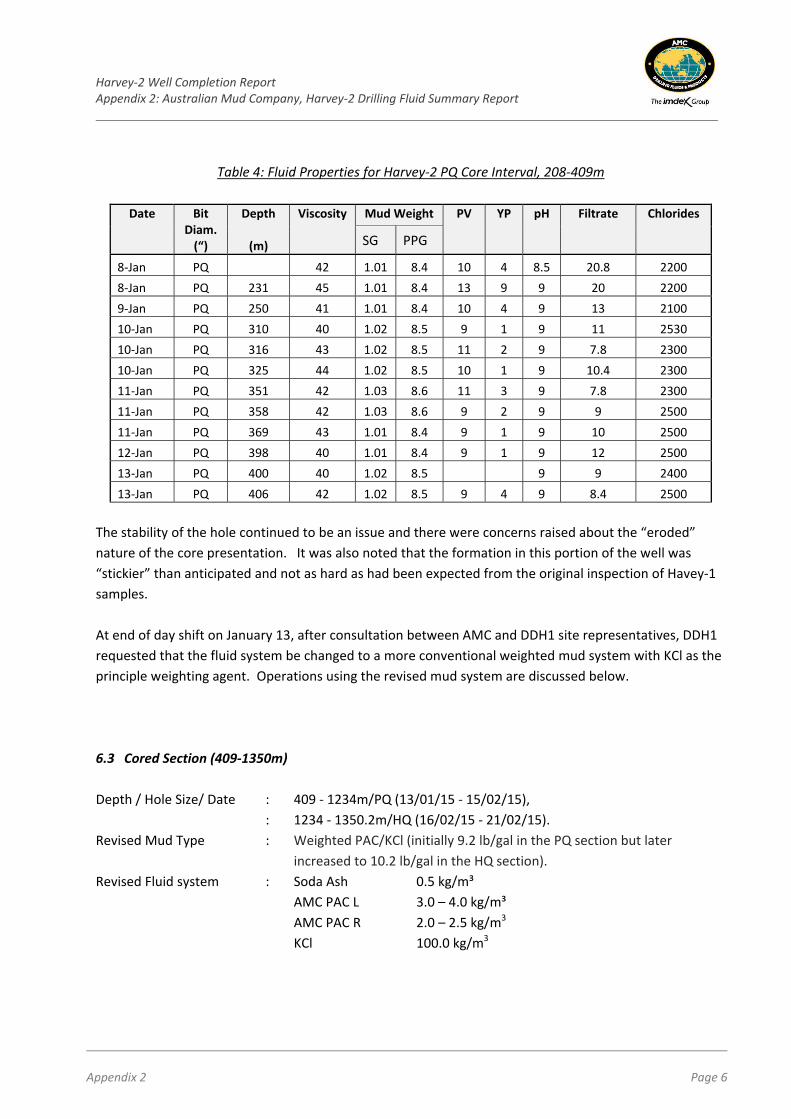
Table 4: Fluid Properties for Harvey‐2 PQ Core Interval, 208‐409m
Date Bit Diam. (“)
Depth
(m)
Viscosity Mud Weight PV YP pH Filtrate Chlorides
SG PPG
8‐Jan PQ 42 1.01 8.4 10 4 8.5 20.8 2200
8‐Jan PQ 231 45 1.01 8.4 13 9 9 20 2200
9‐Jan PQ 250 41 1.01 8.4 10 4 9 13 2100
10‐Jan PQ 310 40 1.02 8.5 9 1 9 11 2530
10‐Jan PQ 316 43 1.02 8.5 11 2 9 7.8 2300
10‐Jan PQ 325 44 1.02 8.5 10 1 9 10.4 2300
11‐Jan PQ 351 42 1.03 8.6 11 3 9 7.8 2300
11‐Jan PQ 358 42 1.03 8.6 9 2 9 9 2500
11‐Jan PQ 369 43 1.01 8.4 9 1 9 10 2500
12‐Jan PQ 398 40 1.01 8.4 9 1 9 12 2500
13‐Jan PQ 400 40 1.02 8.5 9 9 2400
13‐Jan PQ 406 42 1.02 8.5 9 4 9 8.4 2500
The stability of the hole continued to be an issue and there were concerns raised about the “eroded”
nature of the core presentation. It was also noted that the formation in this portion of the well was
“stickier” than anticipated and not as hard as had been expected from the original inspection of Havey‐1
samples.
At end of day shift on January 13, after consultation between AMC and DDH1 site representatives, DDH1
requested that the fluid system be changed to a more conventional weighted mud system with KCl as the
principle weighting agent. Operations using the revised mud system are discussed below.
6.3 Cored Section (409‐1350m)
Depth / Hole Size/ Date : 409 ‐ 1234m/PQ (13/01/15 ‐ 15/02/15),
: 1234 ‐ 1350.2m/HQ (16/02/15 ‐ 21/02/15).
Revised Mud Type : Weighted PAC/KCl (initially 9.2 lb/gal in the PQ section but later
increased to 10.2 lb/gal in the HQ section).
Revised Fluid system : Soda Ash 0.5 kg/m³
AMC PAC L 3.0 – 4.0 kg/m³
AMC PAC R 2.0 – 2.5 kg/m3
KCl 100.0 kg/m3
Harvey‐2 Well Completion Report Appendix 2: Australian Mud Company, Harvey‐2 Drilling Fluid Summary Report
Appendix 2 Page 7
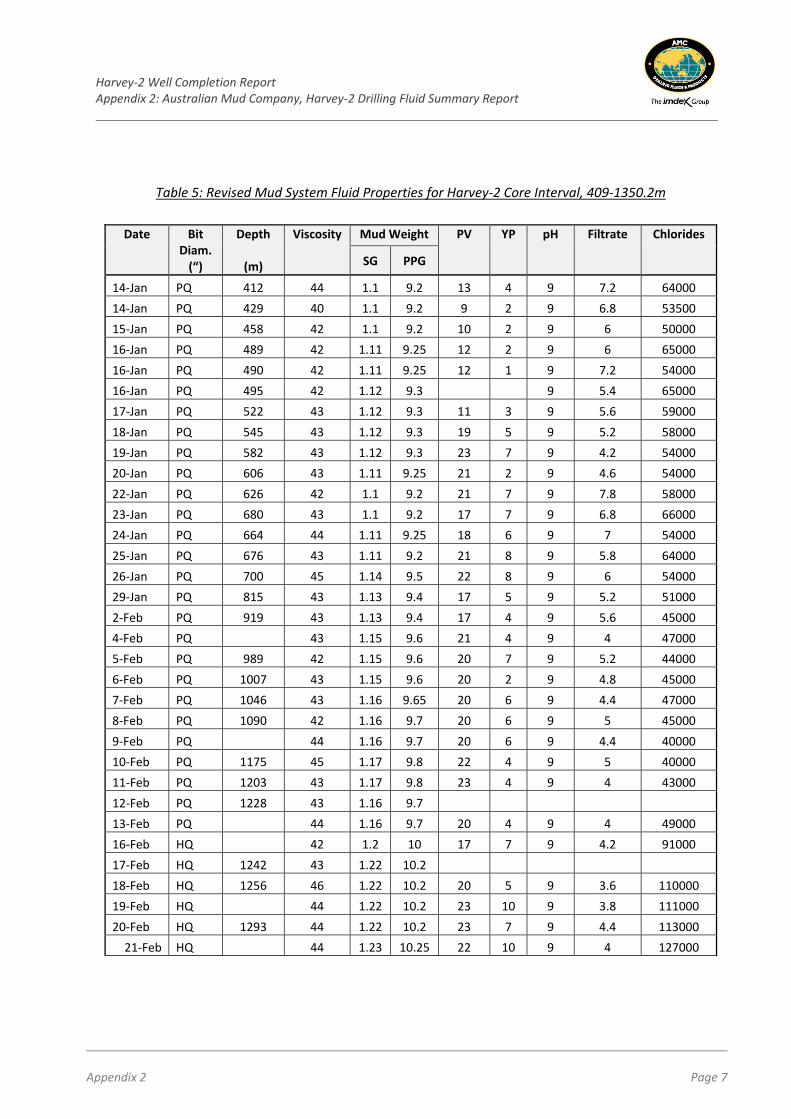
Table 5: Revised Mud System Fluid Properties for Harvey‐2 Core Interval, 409‐1350.2m
Date Bit Diam. (“)
Depth
(m)
Viscosity Mud Weight PV YP pH Filtrate Chlorides
SG PPG
14‐Jan PQ 412 44 1.1 9.2 13 4 9 7.2 64000
14‐Jan PQ 429 40 1.1 9.2 9 2 9 6.8 53500
15‐Jan PQ 458 42 1.1 9.2 10 2 9 6 50000
16‐Jan PQ 489 42 1.11 9.25 12 2 9 6 65000
16‐Jan PQ 490 42 1.11 9.25 12 1 9 7.2 54000
16‐Jan PQ 495 42 1.12 9.3 9 5.4 65000
17‐Jan PQ 522 43 1.12 9.3 11 3 9 5.6 59000
18‐Jan PQ 545 43 1.12 9.3 19 5 9 5.2 58000
19‐Jan PQ 582 43 1.12 9.3 23 7 9 4.2 54000
20‐Jan PQ 606 43 1.11 9.25 21 2 9 4.6 54000
22‐Jan PQ 626 42 1.1 9.2 21 7 9 7.8 58000
23‐Jan PQ 680 43 1.1 9.2 17 7 9 6.8 66000
24‐Jan PQ 664 44 1.11 9.25 18 6 9 7 54000
25‐Jan PQ 676 43 1.11 9.2 21 8 9 5.8 64000
26‐Jan PQ 700 45 1.14 9.5 22 8 9 6 54000
29‐Jan PQ 815 43 1.13 9.4 17 5 9 5.2 51000
2‐Feb PQ 919 43 1.13 9.4 17 4 9 5.6 45000
4‐Feb PQ 43 1.15 9.6 21 4 9 4 47000
5‐Feb PQ 989 42 1.15 9.6 20 7 9 5.2 44000
6‐Feb PQ 1007 43 1.15 9.6 20 2 9 4.8 45000
7‐Feb PQ 1046 43 1.16 9.65 20 6 9 4.4 47000
8‐Feb PQ 1090 42 1.16 9.7 20 6 9 5 45000
9‐Feb PQ 44 1.16 9.7 20 6 9 4.4 40000
10‐Feb PQ 1175 45 1.17 9.8 22 4 9 5 40000
11‐Feb PQ 1203 43 1.17 9.8 23 4 9 4 43000
12‐Feb PQ 1228 43 1.16 9.7
13‐Feb PQ 44 1.16 9.7 20 4 9 4 49000
16‐Feb HQ 42 1.2 10 17 7 9 4.2 91000
17‐Feb HQ 1242 43 1.22 10.2
18‐Feb HQ 1256 46 1.22 10.2 20 5 9 3.6 110000
19‐Feb HQ 44 1.22 10.2 23 10 9 3.8 111000
20‐Feb HQ 1293 44 1.22 10.2 23 7 9 4.4 113000
21‐Feb HQ 44 1.23 10.25 22 10 9 4 127000
Harvey‐2 Well Completion Report Appendix 2: Australian Mud Company, Harvey‐2 Drilling Fluid Summary Report
Appendix 2 Page 8
Fluid properties of the revised KCl mud mix over the rest of the Harvey‐2 hole are shown in Table 5. The
change in mud led to the increased use of AUS DET XTRA in place of PENETROL XTRA; at an addition rate
of 25 litres/ 12hr period or as needed.
As drilling progressed, fluid losses beyond that of hole volume became apparent and Magma Fibre (lost
circulation material) was slowly incorporated into the system at a feed rate of 25lb over a 3 shift period.
Additional fluid was also being added at a rate of 1500 to 4000 litres/shift, depending on the fluid losses
(Table 6). The added fluids comprised either water or a light concentration of 6% KCl with a view to
maintaining consistent viscosity, mud weight parameters and to controlling the increasing levels of
colloidal solids. When it was considered that the solids content was increasing beyond a safe operating
level, the volume on the surface was dumped and replaced with fresh fluid. This ranged from 8 to 20m3 of
fluid.
Table 6: Fluid Additions whilst Drilling with the Revised Mud System
Fluid Additions
Fluid Added (litres) Water Added (litres) Fluid Dumped (litres)
80150 10300 38000
At 1234m the PQ pipe became stuck and after several attempts to remove the pipe, the hole was reduced
to HQ. Coincident with the core size reduction, DDH1 requested that the mud weight be increased to
10.2 lb/gal, running a 22% KCl system. This mud system was maintained for the remainder of the drilling
program until successful completion at TD 1350.2m.
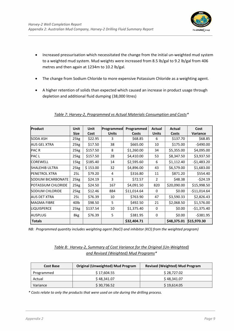
7. Materials Consumption and Cost Analysis of the Harvey‐2 Drilling Fluid Program
A review of programmed vs actual materials consumption in Harvey‐2 is presented in Table 7 and overall
variance in costs for the original (un‐weighted) and revised (weighted) programs is shown in Table 8. The
overall increase in hole costs can be attributed to:
The increased length of time on the hole, which increased fluid consumption through losses
(approximately 2000 litres/day throughout the hole),
Higher than expected formation pressure which was likely to have accentuated fluid losses in
more permeable zones.
Harvey‐2 Well Completion Report Appendix 2: Australian Mud Company, Harvey‐2 Drilling Fluid Summary Report
Appendix 2 Page 9
Increased pressurisation which necessitated the change from the initial un‐weighted mud system
to a weighted mud system. Mud weights were increased from 8.5 lb/gal to 9.2 lb/gal from 406
metres and then again at 1234m to 10.2 lb/gal.
The change from Sodium Chloride to more expensive Potassium Chloride as a weighting agent.
A higher retention of solids than expected which caused an increase in product usage through
depletion and additional fluid dumping (38,000 litres)
Table 7: Harvey‐2, Programmed vs Actual Materials Consumption and Costs*
Product Unit Size
Unit Cost
Programmed Units
Programmed Costs
Actual Units
Actual Costs
Cost Variance
SODA ASH 25kg $22.95 3 $68.85 6 $137.70 $68.85
AUS GEL XTRA 25kg $17.50 38 $665.00 10 $175.00 ‐$490.00
PAC R 25kg $157.50 8 $1,260.00 34 $5,355.00 $4,095.00
PAC L 25kg $157.50 28 $4,410.00 53 $8,347.50 $3,937.50
COREWELL 15kg $185.40 14 $2,595.60 6 $1,112.40 ‐$1,483.20
SHALEHIB ULTRA 25kg $ 153.00 32 $4,896.00 43 $6,579.00 $1,683.00
PENETROL XTRA 25L $79.20 4 $316.80 11 $871.20 $554.40
SODIUM BICARBONATE 25kg $24.19 3 $72.57 2 $48.38 ‐$24.19
POTASSIUM CHLORIDE 25kg $24.50 167 $4,091.50 820 $20,090.00 $15,998.50
SODIUM CHLORIDE 25kg $12.46 884 $11,014.64 0 $0.00 ‐$11,014.64
AUS DET XTRA 25L $76.39 10 $763.90 47 $3,590.33 $2,826.43
MAGMA FIBRE 40lb $98.50 5 $492.50 21 $2,068.50 $1,576.00
LIQUISPERCE 25kg $137.54 10 $1,375.40 0 $0.00 ‐$1,375.40
AUSPLUG 8kg $76.39 5 $381.95 0 $0.00 ‐$381.95
Totals $32,404.71 $48,375.01 $15,970.30
NB: Programmed quantity includes weighting agent (NaCl) and inhibitor (KCl) from the weighted program)
Table 8: Harvey‐2, Summary of Cost Variance for the Original (Un‐Weighted)
and Revised (Weighted) Mud Programs*
Cost Base Original (Unweighted) Mud Program Revised (Weighted) Mud Program
Programmed $ 17,604.55 $ 28,727.02
Actual $ 48,341.07 $ 48,341.07
Variance $ 30,736.52 $ 19,614.05
* Costs relate to only the products that were used on site during the drilling process.
Harvey‐2 Well Completion Report Appendix 2: Australian Mud Company, Harvey‐2 Drilling Fluid Summary Report
Appendix 2 Page 10
8. Conclusions and Recommendations
Based on the results of the Harvey‐2 drilling program, the following recommendations are made in
relation to drill fluid support for future core drilling programs in the Harvey Carbon Sequestration
Project:‐
Use an inhibitive system from the start of the hole, either KCl or an amine based product,
If possible include a PHPA in the fluid system to assist with cutting integrity and to assist with the
removal of excess fines,
Run a weighted system from the start of the coring section and to reduce costs NaCl could be
used.
Monitor seepage losses and correlate to increases in mud weight to assist in controlling over‐
pressurization and use lost circulation material accordingly,
Make allowances for running an additional intermediate casing string.
9. References
Millar, A S and Reeve, J, 2014. GSWA Harvey 1 Well completion and preliminary interpretation report,
southern Perth Basin, GSWA Record 2014/12.
Harvey‐2 Well Completion Report Appendix 2: Australian Mud Company, Harvey‐2 Drilling Fluid Summary Report Attachment A: Pre‐Drill Test Work, Immersion Testing Program 1, September, 2014
Appendix 2, Attachment A Page i
Harvey‐2 Well Completion Report Appendix 2: Australian Mud Company, Harvey‐2 Drilling Fluid Summary Report Attachment A: Pre‐Drill Test Work, Immersion Testing Program 1, September, 2014
Appendix 2, Attachment A Page ii
Harvey‐2 Well Completion Report Appendix 2: Australian Mud Company, Harvey‐2 Drilling Fluid Summary Report Attachment A: Pre‐Drill Test Work, Immersion Testing Program 1, September, 2014
Appendix 2, Attachment A Page iii
Harvey‐2 Well Completion Report Appendix 2: Australian Mud Company, Harvey‐2 Drilling Fluid Summary Report Attachment A: Pre‐Drill Test Work, Immersion Testing Program 1, September, 2014
Appendix 2, Attachment A Page iv
Harvey‐2 Well Completion Report Appendix 2: Australian Mud Company, Harvey‐2 Drilling Fluid Summary Report Attachment B: Pre‐Drill Test Work, Immersion Testing Program 2, November, 2014
Appendix 2, Attachment B Page i
Harvey‐2 Well Completion Report Appendix 2: Australian Mud Company, Harvey‐2 Drilling Fluid Summary Report Attachment B: Pre‐Drill Test Work, Immersion Testing Program 2, November, 2014
Appendix 2, Attachment B Page ii
Harvey‐2 Well Completion Report Appendix 2: Australian Mud Company, Harvey‐2 Drilling Fluid Summary Report Attachment B: Pre‐Drill Test Work, Immersion Testing Program 2, November, 2014
Appendix 2, Attachment B Page iii


![15431433 OIJILNQIOS “ἨΜΖΖ · Thispageis”sawedfarΟῄἳείαἰPrammmzmmtsé]1/26 Chancellor oftheA.'.A:] Persons wishingfor information, assistance, further interpretation,etc](https://img.pdfslide.tips/doc/110x75/5f054c0a7e708231d41243a1/15431433-oijilnqios-aoeoe-thispageisasawedfarprammmzmmts126.jpg)