Embed Size (px)
Citation preview
WARRANTYGreat Planes Model Manufacturing Co. guarantees this kit to be free from defects in both material and
workmanship at the date of purchase. This warranty does not cover any component parts damaged by use or modification. In no case shall Great Planes' liability exceed the original cost of the purchased kit. Further, GreatPlanes reserves the right to change or modify this warranty without notice.
In that Great Planes has no control over the final assembly or material used for final assembly, no liability shall beassumed nor accepted for any damage resulting from the use by the user of the final user-assembled product. By theact of using the user-assembled product, the user accepts all resulting liability.
If the buyers are not prepared to accept the liability associated with the use of this product, they are advisedto return this kit immediately in new and unused condition to the place of purchase.
READ THROUGH THIS INSTRUCTION MANUALFIRST. IT CONTAINS IMPORTANT INSTRUCTIONSAND WARNINGS CONCERNING THE ASSEMBLYAND USE OF THIS MODEL.
FLT246P1 V2.0 Printed in USA Entire Contents © Copyright 2004
P.O. Box 788 Urbana, IL 61803 (217) 398-8970
INSTRUCTION MANUAL
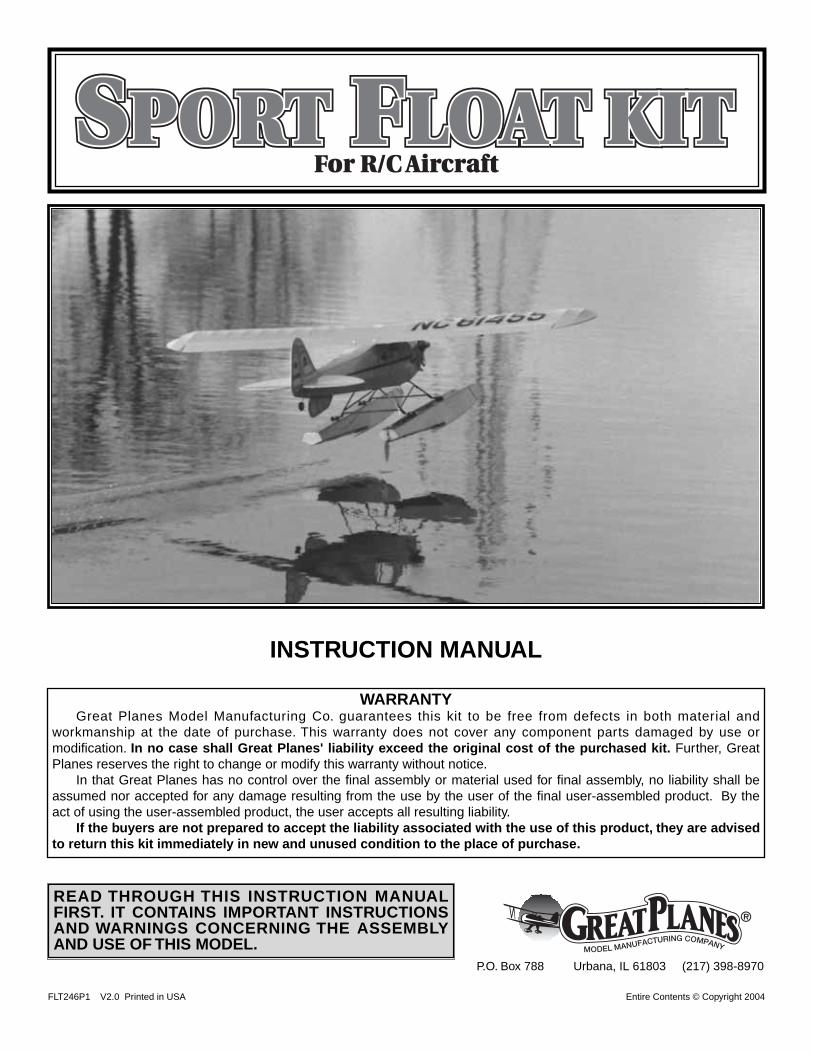
SPORT FLOAT KITSPORT FLOAT KITSPORT FLOAT KITFor R/C Aircraft
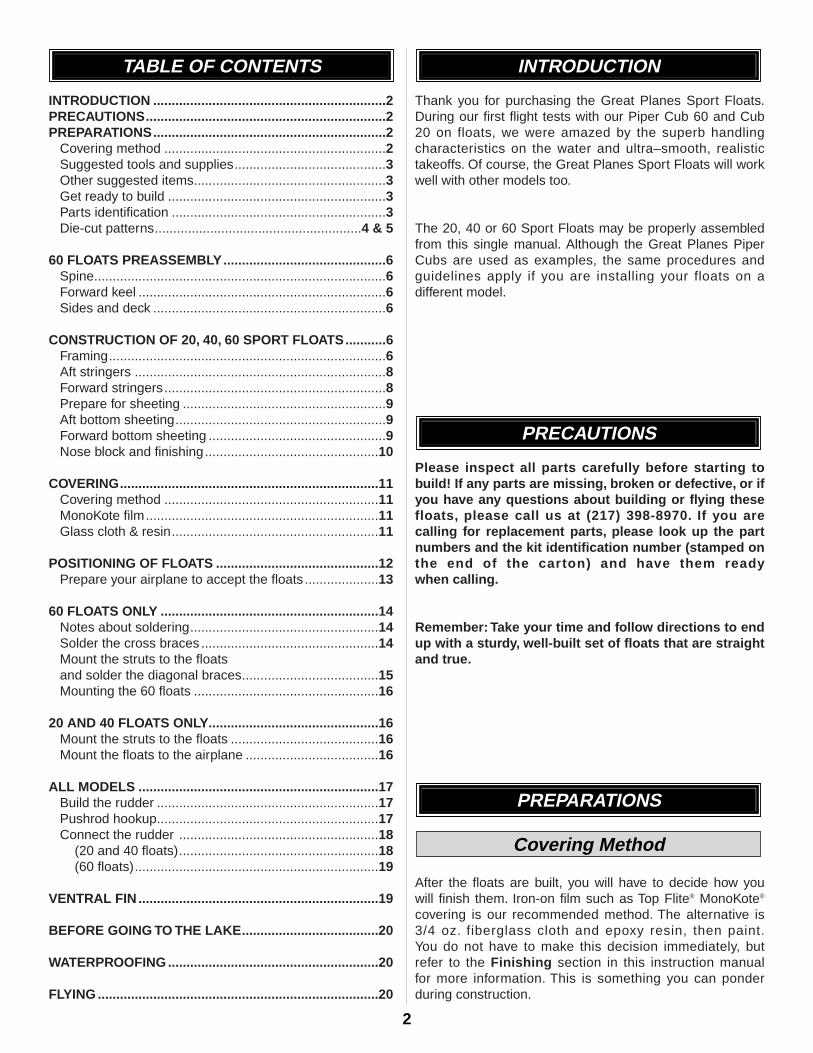
INTRODUCTION ...............................................................2PRECAUTIONS.................................................................2PREPARATIONS...............................................................2
Covering method ............................................................2Suggested tools and supplies.........................................3Other suggested items....................................................3Get ready to build ...........................................................3Parts identification ..........................................................3Die-cut patterns........................................................4 & 5
60 FLOATS PREASSEMBLY............................................6Spine...............................................................................6Forward keel ...................................................................6Sides and deck ...............................................................6
CONSTRUCTION OF 20, 40, 60 SPORT FLOATS...........6Framing...........................................................................6Aft stringers ....................................................................8Forward stringers............................................................8Prepare for sheeting .......................................................9Aft bottom sheeting.........................................................9Forward bottom sheeting ................................................9Nose block and finishing...............................................10
COVERING......................................................................11Covering method ..........................................................11MonoKote film...............................................................11Glass cloth & resin........................................................11
POSITIONING OF FLOATS ............................................12Prepare your airplane to accept the floats ....................13
60 FLOATS ONLY ...........................................................14Notes about soldering...................................................14Solder the cross braces ................................................14Mount the struts to the floatsand solder the diagonal braces.....................................15Mounting the 60 floats ..................................................16
20 AND 40 FLOATS ONLY..............................................16Mount the struts to the floats ........................................16Mount the floats to the airplane ....................................16
ALL MODELS .................................................................17Build the rudder ............................................................17Pushrod hookup............................................................17Connect the rudder ......................................................18
(20 and 40 floats)......................................................18(60 floats)..................................................................19
VENTRAL FIN .................................................................19
BEFORE GOING TO THE LAKE.....................................20
WATERPROOFING.........................................................20
FLYING ............................................................................20
Thank you for purchasing the Great Planes Sport Floats.During our first flight tests with our Piper Cub 60 and Cub20 on floats, we were amazed by the superb handlingcharacteristics on the water and ultra–smooth, realistictakeoffs. Of course, the Great Planes Sport Floats will workwell with other models too.
The 20, 40 or 60 Sport Floats may be properly assembledfrom this single manual. Although the Great Planes PiperCubs are used as examples, the same procedures andguidelines apply if you are installing your floats on adifferent model.
Please inspect all parts carefully before starting tobuild! If any parts are missing, broken or defective, or ifyou have any questions about building or flying thesefloats, please call us at (217) 398-8970. If you arecalling for replacement parts, please look up the partnumbers and the kit identification number (stamped onthe end of the carton) and have them ready when calling.
Remember: Take your time and follow directions to endup with a sturdy, well-built set of floats that are straightand true.
After the floats are built, you will have to decide how youwill finish them. Iron-on film such as Top Flite® MonoKote®
covering is our recommended method. The alternative is3/4 oz. fiberglass cloth and epoxy resin, then paint.You do not have to make this decision immediately, butrefer to the Finishing section in this instruction manual for more information. This is something you can ponderduring construction.
Covering Method
PREPARATIONS
PRECAUTIONS
INTRODUCTIONTABLE OF CONTENTS
2
3
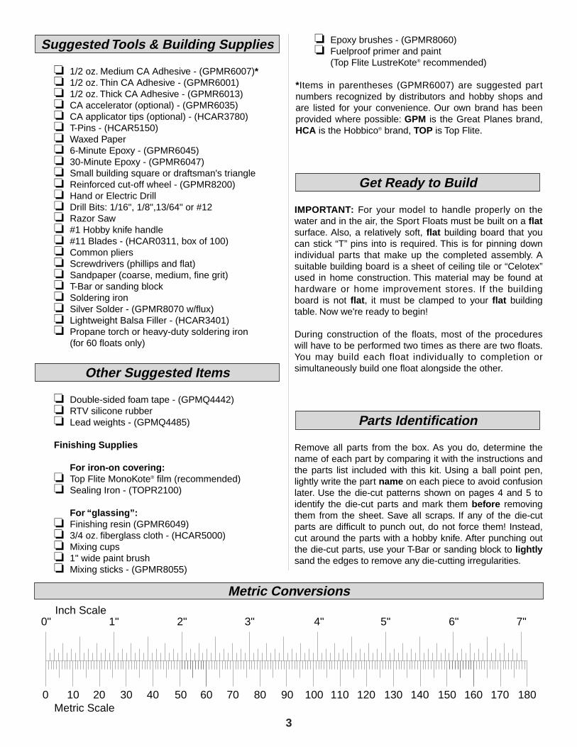
0" 1" 2" 3" 4" 5" 6" 7"
0 10 20 30 40 50 60 70 80 90 100 110 120 130 140 150 160 170 180
Inch Scale
Metric Scale
Metric Conversions
❏ 1/2 oz. Medium CA Adhesive - (GPMR6007)*❏ 1/2 oz. Thin CA Adhesive - (GPMR6001)❏ 1/2 oz. Thick CA Adhesive - (GPMR6013)❏ CA accelerator (optional) - (GPMR6035)❏ CA applicator tips (optional) - (HCAR3780)❏ T-Pins - (HCAR5150)❏ Waxed Paper❏ 6-Minute Epoxy - (GPMR6045)❏ 30-Minute Epoxy - (GPMR6047)❏ Small building square or draftsman's triangle❏ Reinforced cut-off wheel - (GPMR8200)❏ Hand or Electric Drill❏ Drill Bits: 1/16", 1/8",13/64" or #12 ❏ Razor Saw ❏ #1 Hobby knife handle❏ #11 Blades - (HCAR0311, box of 100)❏ Common pliers❏ Screwdrivers (phillips and flat)❏ Sandpaper (coarse, medium, fine grit)❏ T-Bar or sanding block ❏ Soldering iron❏ Silver Solder - (GPMR8070 w/flux)❏ Lightweight Balsa Filler - (HCAR3401)❏ Propane torch or heavy-duty soldering iron
(for 60 floats only)
❏ Double-sided foam tape - (GPMQ4442)❏ RTV silicone rubber❏ Lead weights - (GPMQ4485)
Finishing Supplies
For iron-on covering:❏ Top Flite MonoKote® film (recommended)❏ Sealing Iron - (TOPR2100)
For “glassing”:❏ Finishing resin (GPMR6049)❏ 3/4 oz. fiberglass cloth - (HCAR5000)❏ Mixing cups❏ 1" wide paint brush❏ Mixing sticks - (GPMR8055)
❏ Epoxy brushes - (GPMR8060)❏ Fuelproof primer and paint
(Top Flite LustreKote® recommended)
*Items in parentheses (GPMR6007) are suggested partnumbers recognized by distributors and hobby shops andare listed for your convenience. Our own brand has beenprovided where possible: GPM is the Great Planes brand,HCA is the Hobbico® brand, TOP is Top Flite.
IMPORTANT: For your model to handle properly on thewater and in the air, the Sport Floats must be built on a flatsurface. Also, a relatively soft, flat building board that youcan stick “T” pins into is required. This is for pinning downindividual parts that make up the completed assembly. Asuitable building board is a sheet of ceiling tile or “Celotex”used in home construction. This material may be found athardware or home improvement stores. If the buildingboard is not flat, it must be clamped to your flat buildingtable. Now we're ready to begin!
During construction of the floats, most of the procedureswill have to be performed two times as there are two floats.You may build each float individually to completion orsimultaneously build one float alongside the other.
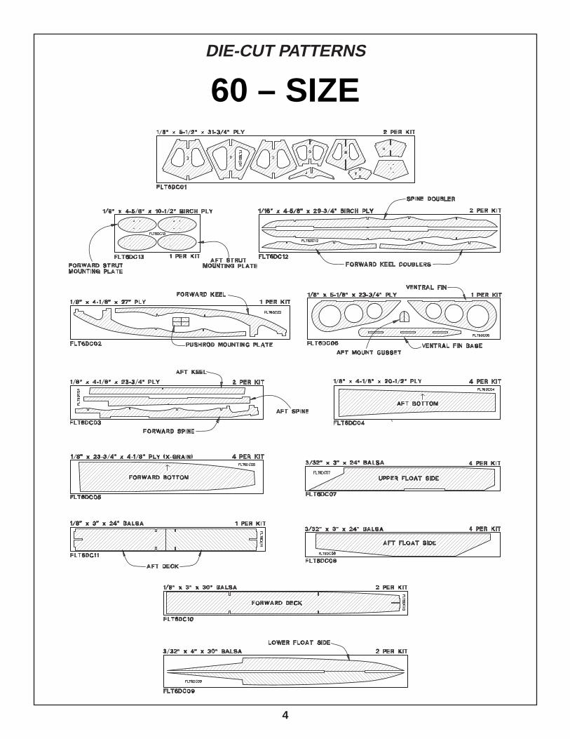
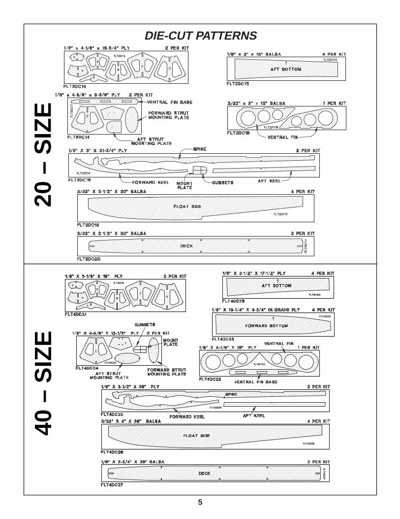
Remove all parts from the box. As you do, determine thename of each part by comparing it with the instructions andthe parts list included with this kit. Using a ball point pen,lightly write the part name on each piece to avoid confusionlater. Use the die-cut patterns shown on pages 4 and 5 toidentify the die-cut parts and mark them before removingthem from the sheet. Save all scraps. If any of the die-cutparts are difficult to punch out, do not force them! Instead,cut around the parts with a hobby knife. After punching outthe die-cut parts, use your T-Bar or sanding block to lightlysand the edges to remove any die-cutting irregularities.
Parts Identification
Get Ready to Build
Other Suggested Items
Suggested Tools & Building Supplies
4
DIE-CUT PATTERNS
60 – SIZE
5
DIE-CUT PATTERNS20
– S
IZE
40 –
SIZ
E
If you are building the 20 or 40 Sports Floats, skip to“Construction of 20, 40, 60 Floats” in the next columnon this page.
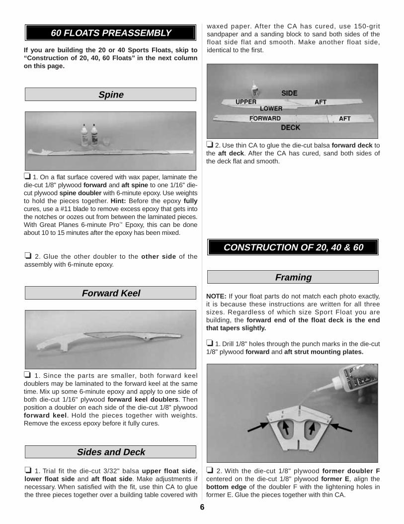
❏ 1. On a flat surface covered with wax paper, laminate thedie-cut 1/8" plywood forward and aft spine to one 1/16" die-cut plywood spine doubler with 6-minute epoxy. Use weightsto hold the pieces together. Hint: Before the epoxy fullycures, use a #11 blade to remove excess epoxy that gets intothe notches or oozes out from between the laminated pieces.With Great Planes 6-minute Pro™ Epoxy, this can be doneabout 10 to 15 minutes after the epoxy has been mixed.
❏ 2. Glue the other doubler to the other side of theassembly with 6-minute epoxy.
❏ 1. Since the parts are smaller, both forward keeldoublers may be laminated to the forward keel at the sametime. Mix up some 6-minute epoxy and apply to one side ofboth die-cut 1/16" plywood forward keel doublers. Thenposition a doubler on each side of the die-cut 1/8" plywoodforward keel. Hold the pieces together with weights.Remove the excess epoxy before it fully cures.
❏ 1. Trial fit the die-cut 3/32" balsa upper float side,lower float side and aft float side. Make adjustments ifnecessary. When satisfied with the fit, use thin CA to gluethe three pieces together over a building table covered with
waxed paper. After the CA has cured, use 150-gritsandpaper and a sanding block to sand both sides of thefloat side flat and smooth. Make another float side,identical to the first.
❏ 2. Use thin CA to glue the die-cut balsa forward deck tothe aft deck. After the CA has cured, sand both sides ofthe deck flat and smooth.
NOTE: If your float parts do not match each photo exactly,it is because these instructions are written for all threesizes. Regardless of which size Sport Float you arebuilding, the forward end of the float deck is the endthat tapers slightly.
❏ 1. Drill 1/8" holes through the punch marks in the die-cut1/8" plywood forward and aft strut mounting plates.
❏ 2. With the die-cut 1/8" plywood former doubler Fcentered on the die-cut 1/8" plywood former E, align thebottom edge of the doubler F with the lightening holes informer E. Glue the pieces together with thin CA.
Framing
CONSTRUCTION OF 20, 40 & 60
Sides and Deck
Forward Keel
Spine
60 FLOATS PREASSEMBLY
6
7
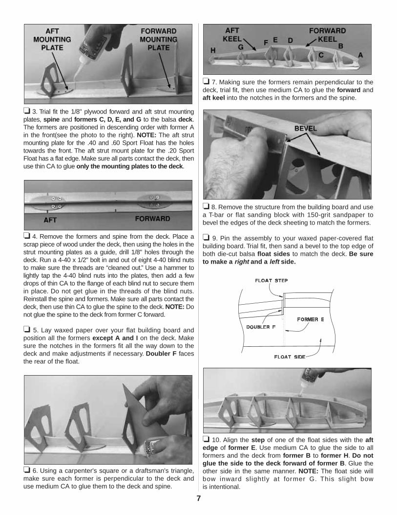
❏ 3. Trial fit the 1/8" plywood forward and aft strut mountingplates, spine and formers C, D, E, and G to the balsa deck.The formers are positioned in descending order with former Ain the front(see the photo to the right). NOTE: The aft strutmounting plate for the .40 and .60 Sport Float has the holestowards the front. The aft strut mount plate for the .20 SportFloat has a flat edge. Make sure all parts contact the deck, thenuse thin CA to glue only the mounting plates to the deck.
❏ 4. Remove the formers and spine from the deck. Place ascrap piece of wood under the deck, then using the holes in thestrut mounting plates as a guide, drill 1/8" holes through thedeck. Run a 4-40 x 1/2" bolt in and out of eight 4-40 blind nutsto make sure the threads are “cleaned out.” Use a hammer tolightly tap the 4-40 blind nuts into the plates, then add a fewdrops of thin CA to the flange of each blind nut to secure themin place. Do not get glue in the threads of the blind nuts.Reinstall the spine and formers. Make sure all parts contact thedeck, then use thin CA to glue the spine to the deck. NOTE: Donot glue the spine to the deck from former C forward.
❏ 5. Lay waxed paper over your flat building board andposition all the formers except A and I on the deck. Makesure the notches in the formers fit all the way down to thedeck and make adjustments if necessary. Doubler F facesthe rear of the float.
❏ 6. Using a carpenter's square or a draftsman's triangle,make sure each former is perpendicular to the deck anduse medium CA to glue them to the deck and spine.
❏ 7. Making sure the formers remain perpendicular to thedeck, trial fit, then use medium CA to glue the forward andaft keel into the notches in the formers and the spine.
❏ 8. Remove the structure from the building board and usea T-bar or flat sanding block with 150-grit sandpaper tobevel the edges of the deck sheeting to match the formers.
❏ 9. Pin the assembly to your waxed paper-covered flatbuilding board. Trial fit, then sand a bevel to the top edge ofboth die-cut balsa float sides to match the deck. Be sureto make a right and a left side.
❏ 10. Align the step of one of the float sides with the aftedge of former E. Use medium CA to glue the side to allformers and the deck from former B to former H. Do notglue the side to the deck forward of former B. Glue theother side in the same manner. NOTE: The float side willbow inward slightly at former G. This sl ight bow is intentional.
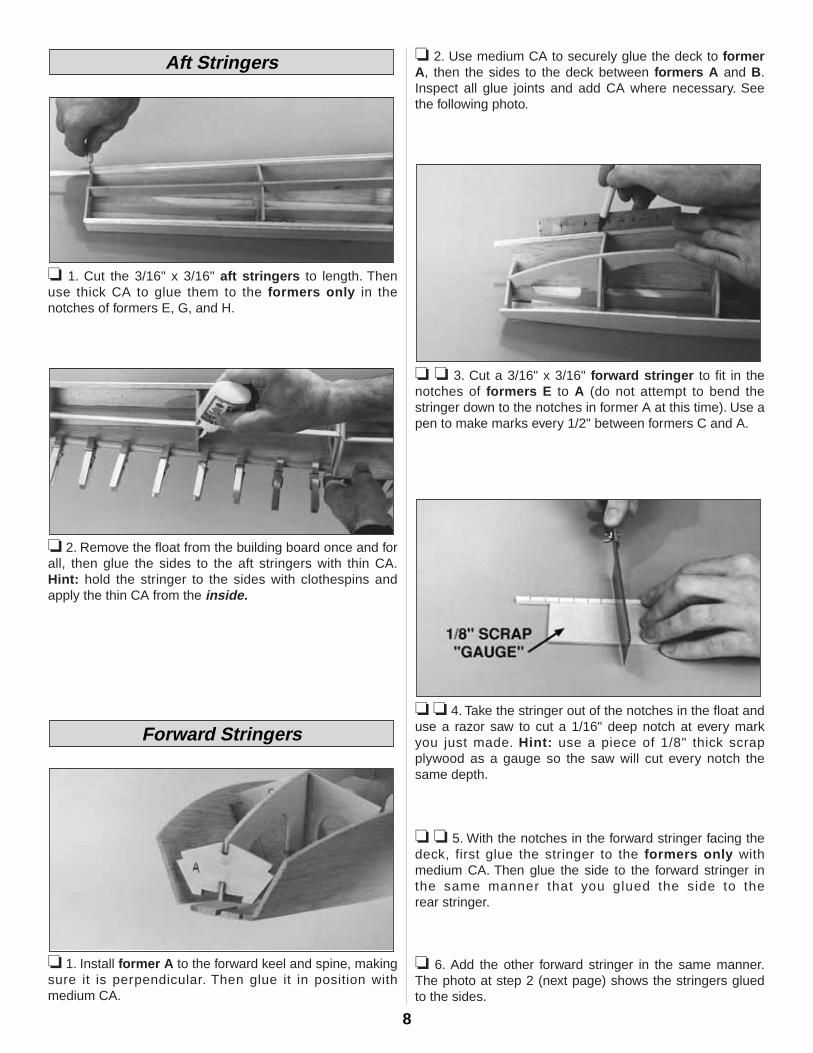
❏ 1. Cut the 3/16" x 3/16" aft stringers to length. Thenuse thick CA to glue them to the formers only in thenotches of formers E, G, and H.
❏ 2. Remove the float from the building board once and forall, then glue the sides to the aft stringers with thin CA.Hint: hold the stringer to the sides with clothespins andapply the thin CA from the inside.
❏ 1. Install former A to the forward keel and spine, makingsure it is perpendicular. Then glue it in position with medium CA.
❏ 2. Use medium CA to securely glue the deck to formerA, then the sides to the deck between formers A and B.Inspect all glue joints and add CA where necessary. Seethe following photo.
❏ ❏ 3. Cut a 3/16" x 3/16" forward stringer to fit in thenotches of formers E to A (do not attempt to bend thestringer down to the notches in former A at this time). Use apen to make marks every 1/2" between formers C and A.
❏ ❏ 4. Take the stringer out of the notches in the float anduse a razor saw to cut a 1/16" deep notch at every markyou just made. Hint: use a piece of 1/8" thick scrapplywood as a gauge so the saw will cut every notch thesame depth.
❏ ❏ 5. With the notches in the forward stringer facing thedeck, first glue the stringer to the formers only withmedium CA. Then glue the side to the forward stringer inthe same manner that you glued the side to the rear stringer.
❏ 6. Add the other forward stringer in the same manner.The photo at step 2 (next page) shows the stringers gluedto the sides.
Forward Stringers
Aft Stringers
8
❏ 1. To provide a good glue joint for the bottom sheeting,use a sanding block and 150-grit sandpaper to trim the sidesheeting down to the side stringers and to bevel theforward and aft keel to the same angle as the formers. Besure to maintain a smooth curve in the float sides whensanding. Use the stringers as a guide.
❏ 2. It has been our experience that ballast is required inorder to move the center of gravity forward when the floatsare mounted on the airplane. This can easily beaccomplished by using 6-minute epoxy to glue the weightinside the floats just behind the front former A. Spreadepoxy over and around the lead weights to prevent themfrom coming loose. We suggest 1 oz. inside each 20 float,1-1/2 oz. inside each 40 float and 2 oz. inside each 60 float.
❏ 1. Trial fit the die-cut 1/8" plywood aft bottom sheets.Note: The 20 floats use die-cut 1/8" balsa aft bottomsheets. The straight edge goes toward the center and
should be placed so it covers half of the keel. Makeadjustments if necessary and bevel the edges of the aftbottom sheets that contact each other in the center.
Note: An embossed arrow is provided on the .40 and .60aft float bottoms as an aid to alignment.
❏ 2. Working on your flat building board, use thick CA toglue one aft bottom sheet to the aft side stringer andformers only. Do not apply CA to the aft keel at this time.
❏ 3. Glue the other aft bottom sheet in position, applyingthick CA to the side stringers, formers and aft keel, gluingboth aft sheets to the keel and each other simultaneously.
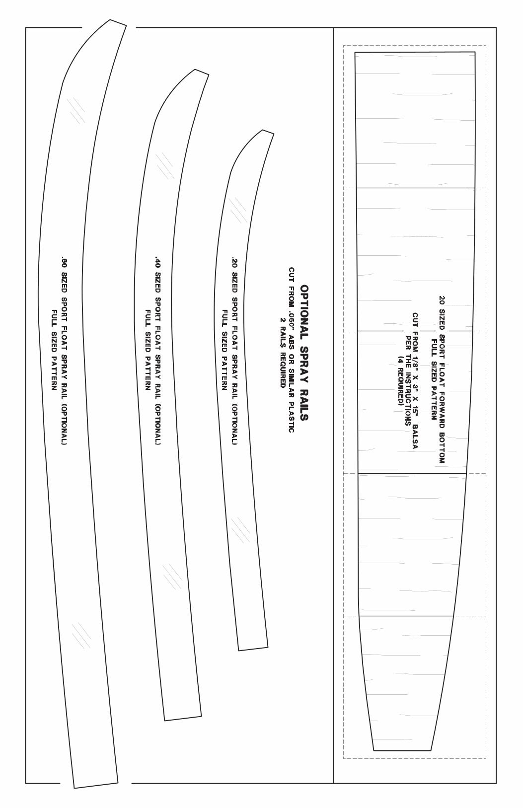
❏ 1. To prepare the forward bottom sheets for one float,cut ten 3-1/2" pieces from a 1/8" x 3" x 30" balsa sheet,then make two cross-grain sheets by gluing 5 piecestogether. Carefully sand the sheets flat using a sandingblock and 150-grit sandpaper.
20 Floats Only
If you are building the 20 Sport Floats, follow thesesteps first to make the bottom forward sheeting.Otherwise, skip these three steps and add thebottom forward sheeting now.
Forward Bottom Sheeting
Aft Bottom Sheeting
Prepare for Sheeting
9
Add the forward bottom sheeting in the same manner asthe aft bottom sheeting:
❏ 1. On the 40 and 60 die-cut 1/8" plywood forwardbottom sheets, there is an arrow indicating the inboardedge of each sheet (although one of the sheets on eachfloat will have to be flipped over). Trial fit the two sheets andbevel the inboard edges that contact each other for a goodglue joint.
❏ 2. Use thick CA to glue one of the sheets to the sidestringer and formers only – do not apply CA to theforward keel.
❏ 3. Apply thick CA to the side stringer, formers and keelto glue the second sheet in position and both sheets to thekeel and each other simultaneously. Use the embossedarrows to aid in final alignment.
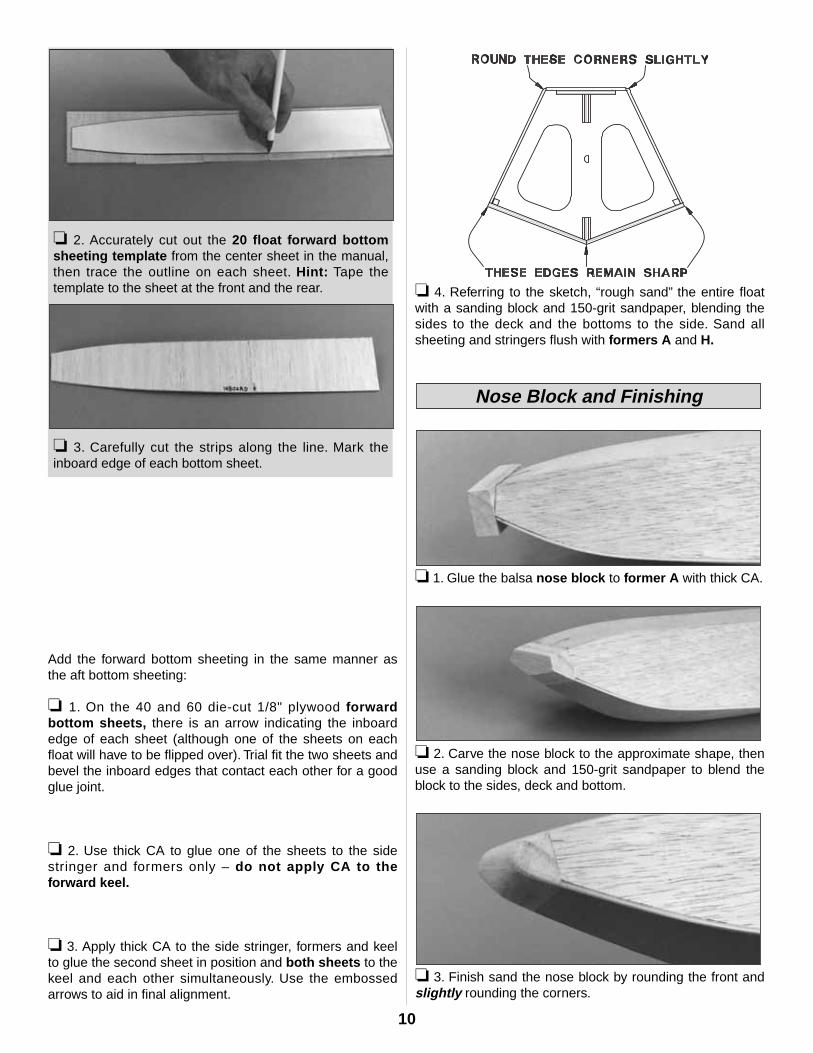
❏ 4. Referring to the sketch, “rough sand” the entire floatwith a sanding block and 150-grit sandpaper, blending thesides to the deck and the bottoms to the side. Sand allsheeting and stringers flush with formers A and H.
❏ 1. Glue the balsa nose block to former A with thick CA.
❏ 2. Carve the nose block to the approximate shape, thenuse a sanding block and 150-grit sandpaper to blend theblock to the sides, deck and bottom.
❏ 3. Finish sand the nose block by rounding the front andslightly rounding the corners.
Nose Block and Finishing
❏ 3. Carefully cut the strips along the line. Mark theinboard edge of each bottom sheet.
❏ 2. Accurately cut out the 20 float forward bottomsheeting template from the center sheet in the manual,then trace the outline on each sheet. Hint: Tape thetemplate to the sheet at the front and the rear.
10
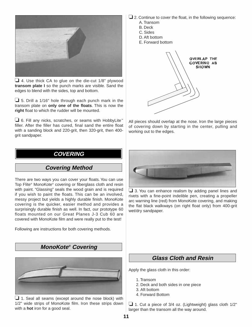
❏ 4. Use thick CA to glue on the die-cut 1/8" plywoodtransom plate I so the punch marks are visible. Sand theedges to blend with the sides, top and bottom.
❏ 5. Drill a 1/16" hole through each punch mark in thetransom plate on only one of the floats. This is now theright float to which the rudder will be mounted.
❏ 6. Fill any nicks, scratches, or seams with HobbyLite™
filler. After the filler has cured, final sand the entire floatwith a sanding block and 220-grit, then 320-grit, then 400-grit sandpaper.
There are two ways you can cover your floats. You can useTop Flite® MonoKote® covering or fiberglass cloth and resinwith paint. “Glassing” seals the wood grain and is requiredif you wish to paint the floats. This can be an involved,messy project but yields a highly durable finish. MonoKotecovering is the quicker, easier method and provides asurprisingly durable finish as well. In fact, our prototype 60floats mounted on our Great Planes J-3 Cub 60 arecovered with MonoKote film and were really put to the test!
Following are instructions for both covering methods.
❏ 1. Seal all seams (except around the nose block) with1/2" wide strips of MonoKote film. Iron these strips downwith a hot iron for a good seal.
❏ 2. Continue to cover the float, in the following sequence:A. TransomB. DeckC. SidesD. Aft bottomE. Forward bottom
All pieces should overlap at the nose. Iron the large piecesof covering down by starting in the center, pulling andworking out to the edges.
❏ 3. You can enhance realism by adding panel lines andrivets with a fine-point indelible pen, creating a propellerarc warning line (red) from MonoKote covering, and makingthe flat black walkways (on right float only) from 400-gritwet/dry sandpaper.
Apply the glass cloth in this order:
1. Transom2. Deck and both sides in one piece3. Aft bottom4. Forward Bottom
❏ 1. Cut a piece of 3/4 oz. (Lightweight) glass cloth 1/2"larger than the transom all the way around.
Glass Cloth and Resin
MonoKote® Covering
Covering Method
COVERING
11
❏ 2. Mix up 1 oz. of f inishing resin fol lowing theinstructions provided in the Great Planes Pro™ EpoxyFinishing Resin kit. Use an epoxy brush to liberally coat thetransom of the float.
❏ 3. Place the cloth on the resin-coated transom, thenbrush the resin through the cloth, removing excess resinfrom the center to the edges. Be sure to allow the excessglass cloth to wrap around the top, sides and bottom of thefloat. Some expert modelers squeegee the excess resin offwith a business card or expired plastic credit card. Let thetransom fully cure. Then with a sanding block and fresh 220grit sandpaper, feather the glass cloth into the float top,sides and bottom.
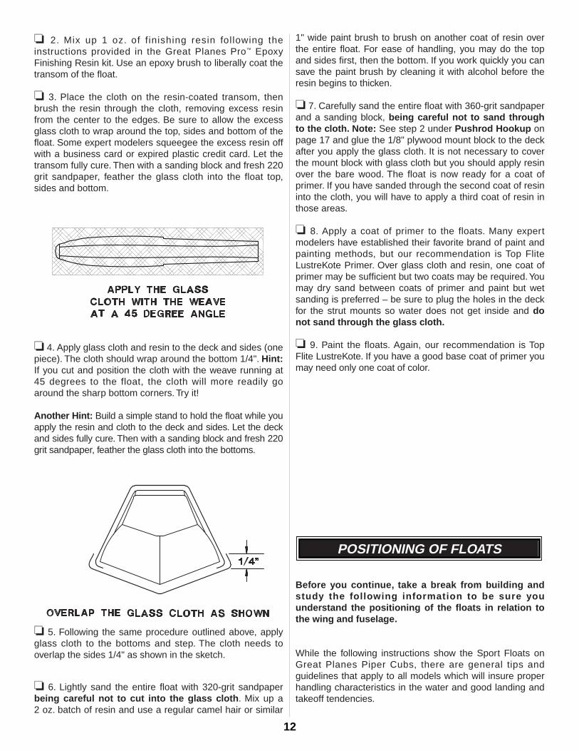
❏ 4. Apply glass cloth and resin to the deck and sides (onepiece). The cloth should wrap around the bottom 1/4". Hint:If you cut and position the cloth with the weave running at45 degrees to the float, the cloth will more readily goaround the sharp bottom corners. Try it!
Another Hint: Build a simple stand to hold the float while youapply the resin and cloth to the deck and sides. Let the deckand sides fully cure. Then with a sanding block and fresh 220grit sandpaper, feather the glass cloth into the bottoms.
❏ 5. Following the same procedure outlined above, applyglass cloth to the bottoms and step. The cloth needs tooverlap the sides 1/4" as shown in the sketch.
❏ 6. Lightly sand the entire float with 320-grit sandpaperbeing careful not to cut into the glass cloth. Mix up a 2 oz. batch of resin and use a regular camel hair or similar
1" wide paint brush to brush on another coat of resin overthe entire float. For ease of handling, you may do the topand sides first, then the bottom. If you work quickly you cansave the paint brush by cleaning it with alcohol before theresin begins to thicken.
❏ 7. Carefully sand the entire float with 360-grit sandpaperand a sanding block, being careful not to sand throughto the cloth. Note: See step 2 under Pushrod Hookup onpage 17 and glue the 1/8" plywood mount block to the deckafter you apply the glass cloth. It is not necessary to coverthe mount block with glass cloth but you should apply resinover the bare wood. The float is now ready for a coat ofprimer. If you have sanded through the second coat of resininto the cloth, you will have to apply a third coat of resin inthose areas.
❏ 8. Apply a coat of primer to the floats. Many expertmodelers have established their favorite brand of paint andpainting methods, but our recommendation is Top FliteLustreKote Primer. Over glass cloth and resin, one coat ofprimer may be sufficient but two coats may be required.Youmay dry sand between coats of primer and paint but wetsanding is preferred – be sure to plug the holes in the deckfor the strut mounts so water does not get inside and donot sand through the glass cloth.
❏ 9. Paint the floats. Again, our recommendation is TopFlite LustreKote. If you have a good base coat of primer youmay need only one coat of color.
Before you continue, take a break from building andstudy the following information to be sure youunderstand the positioning of the floats in relation tothe wing and fuselage.
While the following instructions show the Sport Floats onGreat Planes Piper Cubs, there are general tips andguidelines that apply to all models which will insure properhandling characteristics in the water and good landing andtakeoff tendencies.
POSITIONING OF FLOATS
12
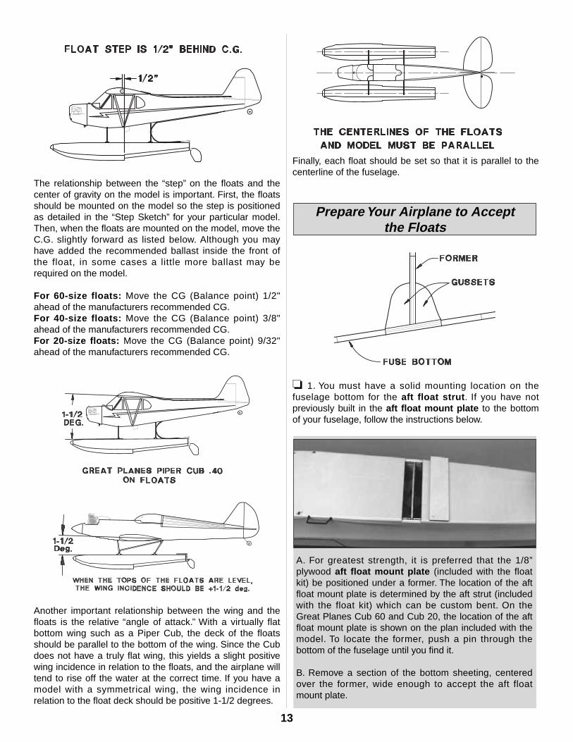
The relationship between the “step” on the floats and thecenter of gravity on the model is important. First, the floatsshould be mounted on the model so the step is positionedas detailed in the “Step Sketch” for your particular model.Then, when the floats are mounted on the model, move theC.G. slightly forward as listed below. Although you mayhave added the recommended ballast inside the front ofthe float, in some cases a little more ballast may berequired on the model.
For 60-size floats: Move the CG (Balance point) 1/2"ahead of the manufacturers recommended CG.For 40-size floats: Move the CG (Balance point) 3/8"ahead of the manufacturers recommended CG.For 20-size floats: Move the CG (Balance point) 9/32"ahead of the manufacturers recommended CG.
Another important relationship between the wing and thefloats is the relative “angle of attack.’’ With a virtually flatbottom wing such as a Piper Cub, the deck of the floatsshould be parallel to the bottom of the wing. Since the Cubdoes not have a truly flat wing, this yields a slight positivewing incidence in relation to the floats, and the airplane willtend to rise off the water at the correct time. If you have amodel with a symmetrical wing, the wing incidence inrelation to the float deck should be positive 1-1/2 degrees.
Finally, each float should be set so that it is parallel to thecenterline of the fuselage.
❏ 1. You must have a solid mounting location on thefuselage bottom for the aft float strut. If you have notpreviously built in the aft float mount plate to the bottomof your fuselage, follow the instructions below.
A. For greatest strength, it is preferred that the 1/8”plywood aft float mount plate (included with the floatkit) be positioned under a former. The location of the aftfloat mount plate is determined by the aft strut (includedwith the float kit) which can be custom bent. On theGreat Planes Cub 60 and Cub 20, the location of the aftfloat mount plate is shown on the plan included with themodel. To locate the former, push a pin through thebottom of the fuselage until you find it.
B. Remove a section of the bottom sheeting, centeredover the former, wide enough to accept the aft floatmount plate.
Prepare Your Airplane to Acceptthe Floats
13
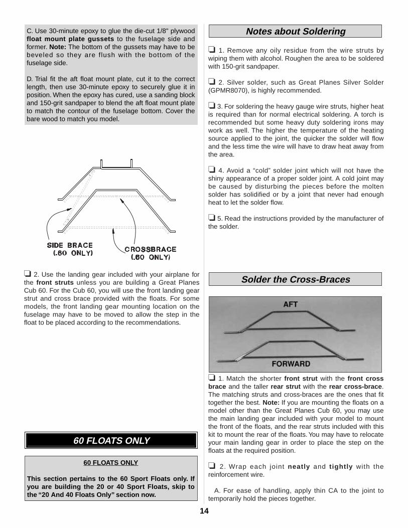
❏ 2. Use the landing gear included with your airplane forthe front struts unless you are building a Great PlanesCub 60. For the Cub 60, you will use the front landing gearstrut and cross brace provided with the floats. For somemodels, the front landing gear mounting location on thefuselage may have to be moved to allow the step in thefloat to be placed according to the recommendations.
❏ 1. Remove any oily residue from the wire struts bywiping them with alcohol. Roughen the area to be solderedwith 150-grit sandpaper.
❏ 2. Silver solder, such as Great Planes Silver Solder(GPMR8070), is highly recommended.
❏ 3. For soldering the heavy gauge wire struts, higher heatis required than for normal electrical soldering. A torch isrecommended but some heavy duty soldering irons maywork as well. The higher the temperature of the heatingsource applied to the joint, the quicker the solder will flowand the less time the wire will have to draw heat away fromthe area.
❏ 4. Avoid a “cold” solder joint which will not have theshiny appearance of a proper solder joint. A cold joint maybe caused by disturbing the pieces before the moltensolder has solidified or by a joint that never had enoughheat to let the solder flow.
❏ 5. Read the instructions provided by the manufacturer ofthe solder.
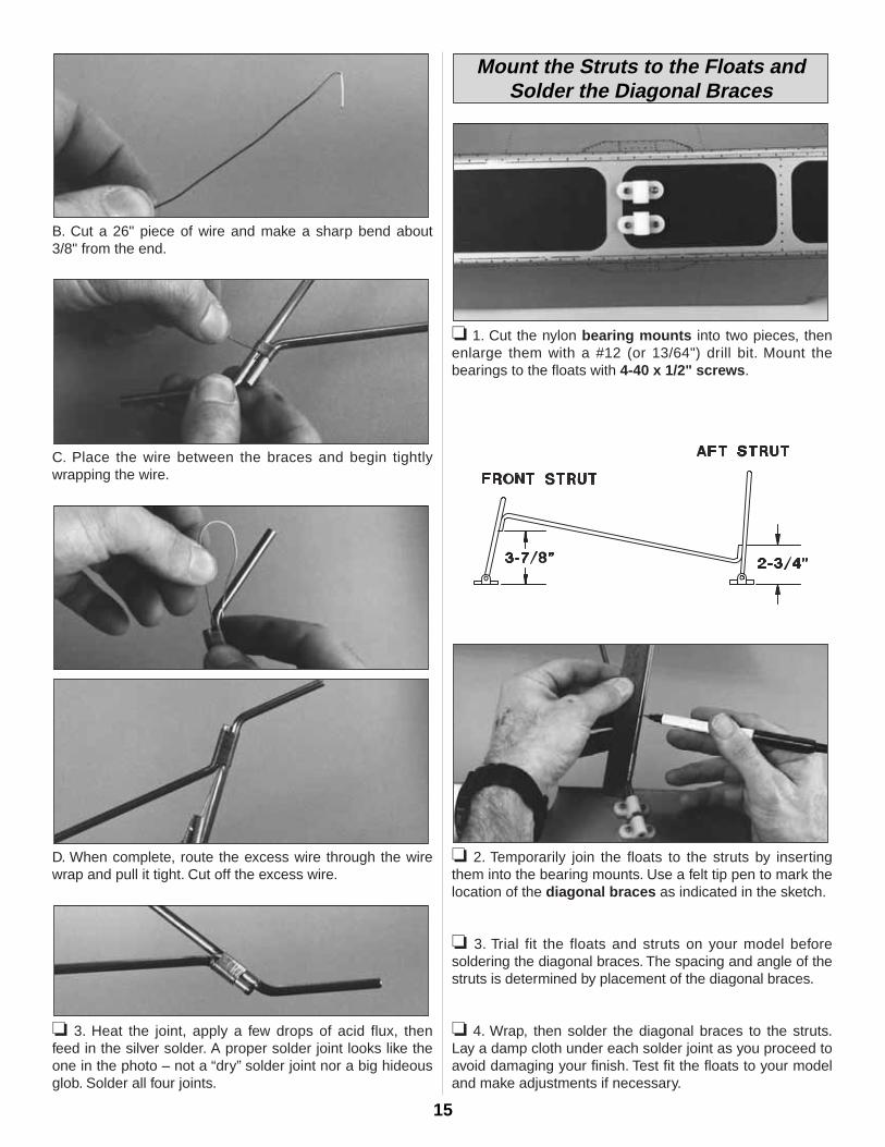
❏ 1. Match the shorter front strut with the front crossbrace and the taller rear strut with the rear cross-brace.The matching struts and cross-braces are the ones that fittogether the best. Note: If you are mounting the floats on amodel other than the Great Planes Cub 60, you may usethe main landing gear included with your model to mountthe front of the floats, and the rear struts included with thiskit to mount the rear of the floats. You may have to relocateyour main landing gear in order to place the step on thefloats at the required position.
❏ 2. Wrap each joint neatly and tightly with thereinforcement wire.
A. For ease of handling, apply thin CA to the joint totemporarily hold the pieces together.
Solder the Cross-Braces
Notes about Soldering
60 FLOATS ONLY
This section pertains to the 60 Sport Floats only. Ifyou are building the 20 or 40 Sport Floats, skip tothe “20 And 40 Floats Only” section now.
60 FLOATS ONLY
C. Use 30-minute epoxy to glue the die-cut 1/8" plywoodfloat mount plate gussets to the fuselage side andformer. Note: The bottom of the gussets may have to bebeveled so they are flush with the bottom of the fuselage side.
D. Trial fit the aft float mount plate, cut it to the correctlength, then use 30-minute epoxy to securely glue it inposition. When the epoxy has cured, use a sanding blockand 150-grit sandpaper to blend the aft float mount plateto match the contour of the fuselage bottom. Cover thebare wood to match you model.
14
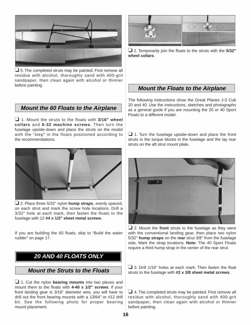
B. Cut a 26" piece of wire and make a sharp bend about3/8" from the end.
C. Place the wire between the braces and begin tightlywrapping the wire.
D. When complete, route the excess wire through the wirewrap and pull it tight. Cut off the excess wire.
❏ 3. Heat the joint, apply a few drops of acid flux, thenfeed in the silver solder. A proper solder joint looks like theone in the photo – not a “dry” solder joint nor a big hideousglob. Solder all four joints.
❏ 1. Cut the nylon bearing mounts into two pieces, thenenlarge them with a #12 (or 13/64") drill bit. Mount thebearings to the floats with 4-40 x 1/2" screws.
❏ 2. Temporarily join the floats to the struts by insertingthem into the bearing mounts. Use a felt tip pen to mark thelocation of the diagonal braces as indicated in the sketch.
❏ 3. Trial fit the floats and struts on your model beforesoldering the diagonal braces. The spacing and angle of thestruts is determined by placement of the diagonal braces.
❏ 4. Wrap, then solder the diagonal braces to the struts.Lay a damp cloth under each solder joint as you proceed toavoid damaging your finish. Test fit the floats to your modeland make adjustments if necessary.
Mount the Struts to the Floats andSolder the Diagonal Braces
15
❏ 5. The completed struts may be painted. First remove allresidue with alcohol, thoroughly sand with 400-gritsandpaper, then clean again with alcohol or thinner before painting.
❏ 1. Mount the struts to the floats with 3/16" wheelcollars and 6-32 machine screws. Then turn the fuselage upside-down and place the struts on the modelwith the “step” in the floats positioned according to the recommendations.
❏ 2. Place three 5/32" nylon hump straps, evenly spaced,on each strut and mark the screw hole locations. Drill a3/32" hole at each mark, then fasten the floats to thefuselage with 12 #4 x 1/2" sheet metal screws.
If you are building the 60 floats, skip to “Build the waterrudder” on page 17.
❏ 1. Cut the nylon bearing mounts into two pieces andmount them to the floats with 4-40 x 1/2" screws. If yourfront landing gear is 3/16" diameter wire, you will have todrill out the front bearing mounts with a 13/64" or #12 drillbit. See the following photo for proper bear ingmount placement.
❏ 2. Temporarily join the floats to the struts with the 5/32"wheel collars.
The following instructions show the Great Planes J-3 Cub20 and 40. Use the instructions, sketches and photographsas a general guide if you are mounting the 20 or 40 SportFloats to a different model.
❏ 1. Turn the fuselage upside-down and place the frontstruts in the torque blocks in the fuselage and the lay rearstruts on the aft strut mount plate.
❏ 2. Mount the front struts to the fuselage as they werewith the conventional landing gear, then place two nylon5/32" hump straps on the rear strut 3/8" from the fuselageside. Mark the strap locations. Note: The 40 Sport Floatsrequire a third hump strap in the center of the rear strut.
❏ 3. Drill 1/16" holes at each mark. Then fasten the floatstruts to the fuselage with #2 x 3/8 sheet metal screws.
❏ 4. The completed struts may be painted. First remove allresidue with alcohol, thoroughly sand with 400-gritsandpaper, then clean again with alcohol or thinner before painting.
Mount the Floats to the Airplane
Mount the Struts to the Floats
20 AND 40 FLOATS ONLY
Mount the 60 Floats to the Airplane
16
❏ 1. Install the wheel collar and the brass tube bearingon the rudder shaft. Use the 4-40 x 1/4" socket head capscrew and 4-40 lock nut to mount the rudder to therudder bracket, then silver solder the rudder bracket to therudder shaft. Do not solder the brass tube to the ruddershaft. Note: The 60 and 40 floats require a brass tube,wheel collar, then another brass tube. Refer to the sketchfor each assembly.
❏ 2. Lock the wheel collar so the rudder shaft cannot slideup and down in the brass tube. Note: on the 60 and 40rudder, lock the wheel collar so the rudder shaft cannotslide up and down on the bottom brass tube.
❏ 3. Cut the threaded portion of the rudder shaft so 3/4" ofthe thread remains, then screw on the nylon swivel 1/8"past the end.
❏ 4. Loosely install the rudder on the right float with two flatstraps, two 1/8" hump straps and four #2 x 3/8" sheet metalscrews. Adjust the bottom of the rudder bracket so it is evenwith the bottom of the transom, then tighten the screws.
Note: Do not overtighten the 4-40 screw and nut that securesthe rudder to the bracket. The rudder must be able to pivotupward in case it hits a foreign object in the water – or the shore.
❏ 1. With the floats mounted to the model, solder athreaded coupler to one end of the braided cable, thenthread on the nylon swivel clevis. Slide the cable into thepushrod guide tube.
❏ 2. Position a die-cut 1/8" mount plate on the deck of thefloat 3" from the rear. Remove the cover ing fromunderneath, then glue it in position. Hint: Cover the mountplate to match your floats before you glue it in place.
Pushrod Hookup
Build the Water Rudder
ALL MODELS
17
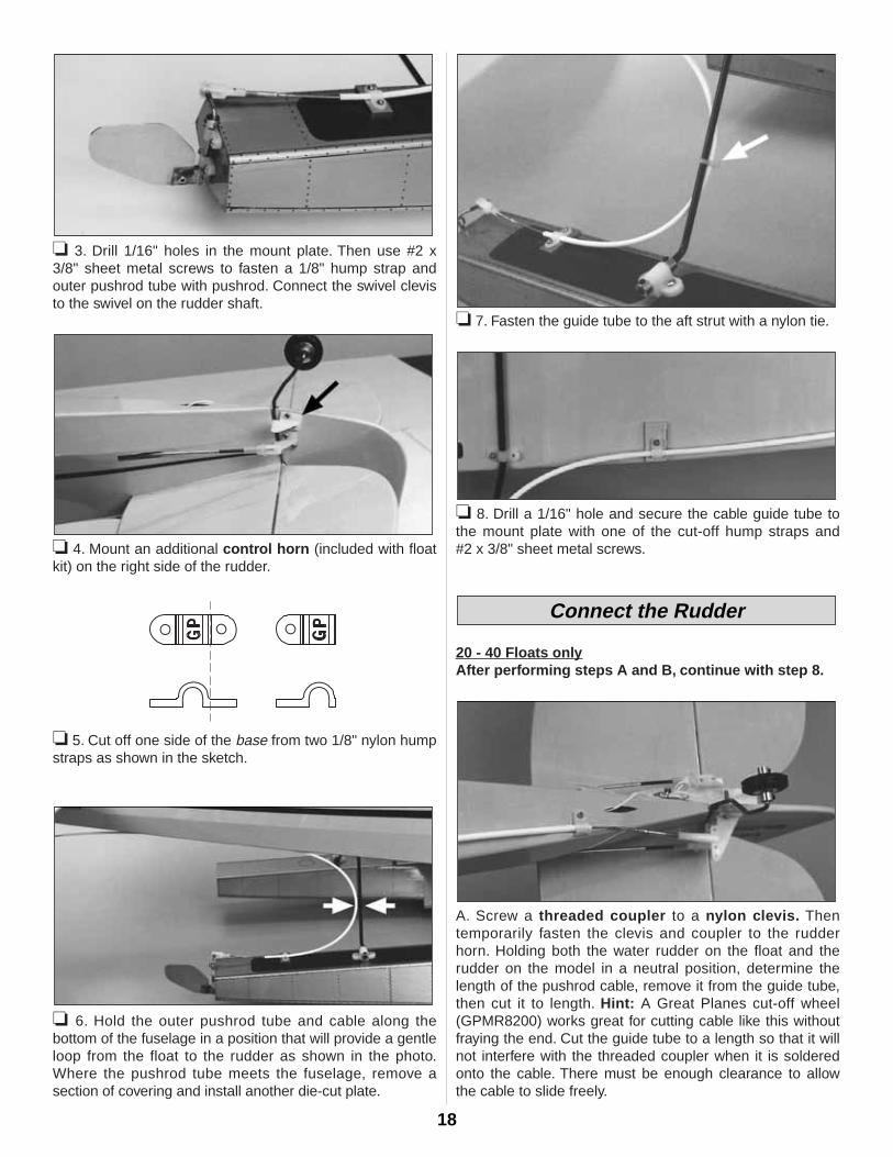
❏ 3. Drill 1/16" holes in the mount plate. Then use #2 x3/8" sheet metal screws to fasten a 1/8" hump strap andouter pushrod tube with pushrod. Connect the swivel clevisto the swivel on the rudder shaft.
❏ 4. Mount an additional control horn (included with floatkit) on the right side of the rudder.
❏ 5. Cut off one side of the base from two 1/8" nylon humpstraps as shown in the sketch.
❏ 6. Hold the outer pushrod tube and cable along thebottom of the fuselage in a position that will provide a gentleloop from the float to the rudder as shown in the photo.Where the pushrod tube meets the fuselage, remove asection of covering and install another die-cut plate.
❏ 7. Fasten the guide tube to the aft strut with a nylon tie.
❏ 8. Drill a 1/16" hole and secure the cable guide tube tothe mount plate with one of the cut-off hump straps and #2 x 3/8" sheet metal screws.
20 - 40 Floats onlyAfter performing steps A and B, continue with step 8.
A. Screw a threaded coupler to a nylon clevis. Thentemporarily fasten the clevis and coupler to the rudderhorn. Holding both the water rudder on the float and therudder on the model in a neutral position, determine thelength of the pushrod cable, remove it from the guide tube,then cut it to length. Hint: A Great Planes cut-off wheel(GPMR8200) works great for cutting cable like this withoutfraying the end. Cut the guide tube to a length so that it willnot interfere with the threaded coupler when it is solderedonto the cable. There must be enough clearance to allowthe cable to slide freely.
Connect the Rudder
18
Note: Before reinstalling the cable into the guide, apply alight coat of oil or petroleum jelly to the cable to preventfuture corrosion.
B. Remove the threaded coupler from the nylon clevis, slidethe cable back into the outer pushrod tube, then solder thecable to the coupler. Thread the clevis back onto thecoupler. Then attach it to the rudder horn. Make finaladjustments by screwing or unscrewing the nylon clevis ateither end of the cable.
60 Floats Only
After performing steps A and B, continue with step 8.
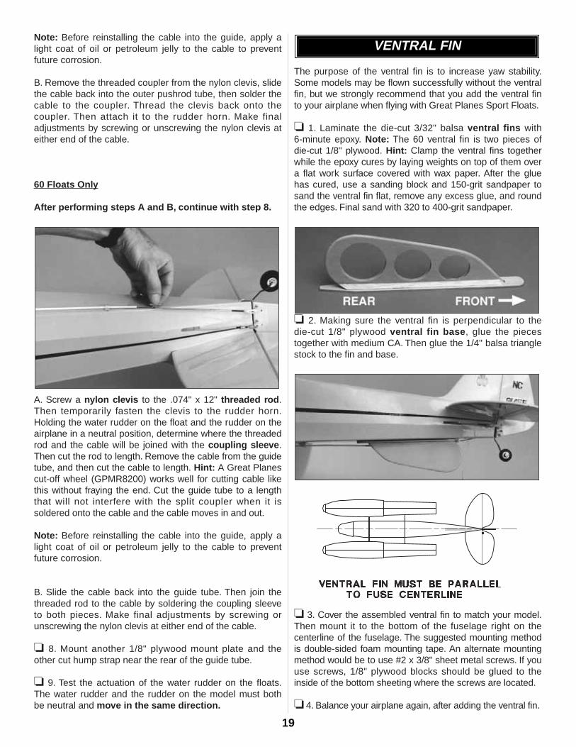
A. Screw a nylon clevis to the .074" x 12" threaded rod.Then temporarily fasten the clevis to the rudder horn.Holding the water rudder on the float and the rudder on theairplane in a neutral position, determine where the threadedrod and the cable will be joined with the coupling sleeve.Then cut the rod to length. Remove the cable from the guidetube, and then cut the cable to length. Hint: A Great Planescut-off wheel (GPMR8200) works well for cutting cable likethis without fraying the end. Cut the guide tube to a lengththat will not interfere with the split coupler when it issoldered onto the cable and the cable moves in and out.
Note: Before reinstalling the cable into the guide, apply alight coat of oil or petroleum jelly to the cable to preventfuture corrosion.
B. Slide the cable back into the guide tube. Then join thethreaded rod to the cable by soldering the coupling sleeveto both pieces. Make final adjustments by screwing orunscrewing the nylon clevis at either end of the cable.
❏ 8. Mount another 1/8" plywood mount plate and theother cut hump strap near the rear of the guide tube.
❏ 9. Test the actuation of the water rudder on the floats.The water rudder and the rudder on the model must bothbe neutral and move in the same direction.
The purpose of the ventral fin is to increase yaw stability.Some models may be flown successfully without the ventralfin, but we strongly recommend that you add the ventral finto your airplane when flying with Great Planes Sport Floats.
❏ 1. Laminate the die-cut 3/32" balsa ventral fins with 6-minute epoxy. Note: The 60 ventral fin is two pieces ofdie-cut 1/8" plywood. Hint: Clamp the ventral fins togetherwhile the epoxy cures by laying weights on top of them overa flat work surface covered with wax paper. After the gluehas cured, use a sanding block and 150-grit sandpaper tosand the ventral fin flat, remove any excess glue, and roundthe edges. Final sand with 320 to 400-grit sandpaper.
❏ 2. Making sure the ventral fin is perpendicular to the die-cut 1/8" plywood ventral fin base, glue the piecestogether with medium CA. Then glue the 1/4" balsa trianglestock to the fin and base.
❏ 3. Cover the assembled ventral fin to match your model.Then mount it to the bottom of the fuselage right on thecenterline of the fuselage. The suggested mounting methodis double-sided foam mounting tape. An alternate mountingmethod would be to use #2 x 3/8" sheet metal screws. If youuse screws, 1/8" plywood blocks should be glued to theinside of the bottom sheeting where the screws are located.
❏ 4. Balance your airplane again, after adding the ventral fin.
VENTRAL FIN
19
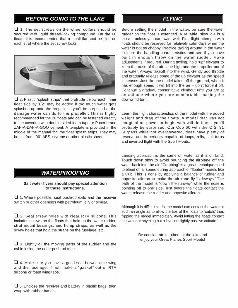
❏ 1. The set screws on the wheel collars should besecured with liquid thread-locking compound. On the 60floats, it is recommended that a small flat spot be filed oneach strut where the set screw locks.
❏ 2. Plastic “splash strips” that protrude below each innerfloat side by 1/2" may be added if too much water getssplashed up onto the propeller – you'll be surprised at thedamage water can do to the propeller. This is highlyrecommended for the 20 floats and can be fastened directlyto the covering with double-sided foam tape or Pacer brandZAP-A-DAP-A-GOO cement. A template is provided in themiddle of the manual for the float splash strips. They maybe cut from .06" ABS, styrene or other plastic sheet.
Salt water flyers should pay special attentionto these instructions.
❏ 1. Where possible, seal pushrod exits and the receiverswitch or other openings with petroleum jelly or similar.
❏ 2. Seal screw holes with clear RTV silicone. Thisincludes screws on the floats that hold on the water rudder,strut mount bearings, and hump straps, as well as thescrew holes that hold the straps on the fuselage, etc.
❏ 3. Lightly oil the moving parts of the rudder and thecable inside the outer pushrod tube.
❏ 4. Make sure you have a good seal between the wingand the fuselage. If not, make a “gasket” out of RTVsilicone or foam wing tape.
❏ 5. Enclose the receiver and battery in plastic bags, thenwrap with rubber bands.
Before setting the model in the water, be sure the waterrudder on the float is extended. A reliable, slow idle is amust – unless you can swim well! First flight attempts withfloats should be reserved for relatively calm days when thewater is not so choppy. Practice taxiing around in the waterto learn the handling characteristics and see if you havebuilt in enough throw on the water rudder. Makeadjustments if required. During taxiing, hold “up” elevator tokeep the nose of the airplane high and the propeller out ofthe water. Always takeoff into the wind. Gently add throttleand gradually release some of the up elevator as the speedincreases. Just like the model takes off the ground, when ithas enough speed it will lift into the air – don't force it off.Continue a gradual, conservative climbout until you are atan alt i tude where you are comfor table making thedownwind turn.
Learn the flight characteristics of the model with the addedweight and drag of the floats. A model that was notmarginal on power to begin with will do fine – you'llprobably be surprised. Our Cub 60 with the O.S. 91Surpass while not overpowered, does have plenty ofreserve and is perfectly capable of loops, rolls, stall turnsand inverted flight with the Sport Floats.
Landing approach is the same on water as it is on land.Touch down slow to avoid bouncing the airplane off thewater back into the air. “Crabbing” is a great technique usedto bleed off airspeed during approach of “floater” models likea Cub. This is done by applying a balance of rudder andopposite aileron to make the airplane fly “sideways.” Thepath of the model is “down the runway” while the nose ispointing off to one side. Just before the floats contact thewater, release the rudder and opposite aileron.
Although it is difficult to do, the model can contact the water atsuch an angle as to allow the tips of the floats to “catch,” thusflipping the model immediately. Avoid letting the floats contactthe water at anything but a level or slightly positive attitude.
Be considerate to others at the lake and enjoy your Great Planes Sport Floats!
FLYING
WATERPROOFING
BEFORE GOING TO THE LAKE


![DEVELOPMENT OF NEW ANTI-CORROSION STEEL FOR COTS OF CRUDE OIL … · Crude Oil type Gas [vol%] The inside of the COT is washed and cleaned in advance in order to carry out the survey](https://img.pdfslide.tips/doc/110x75/5eb1bdaea62b6645f4652fb1/development-of-new-anti-corrosion-steel-for-cots-of-crude-oil-crude-oil-type-gas.jpg)