Embed Size (px)
Citation preview
— GGPPSS TTrraacckkeerr —
For Vehicle
<GPS+GSM+SMS/GPRS>S
使用说明书
User Manual V1.4
MODEL:TK116
- 车载 GPS定位器-- ------
目录/CATALOG
一、产品功能、规格 .................................... 1
1.1 产品功能 ........................................ 1
1.2 产品规格 ........................................ 2
二、产品结构、配件 .................................... 3
2.1 产品结构 ........................................ 3
2.2 产品配件 ........................................ 4
三、安装 SIM 卡 ............................................ 5
3.1 安装前的准备 ................................ 5
3.2 SIM 卡的安装 ................................ 5
3.3 取出 SIM 卡 .................................. 6
四、终端安装 ................................................ 7
4.1 安装设备到车辆 ............................ 7
4.2 终端如何接线 ................................ 8
4.3 继电器接线 .................................. 12
4.4 安装麦克风 ................................. 12
4.5 安装 SOS 求救按钮 .................... 13
五、开启/关闭终端 .................................... 13
5.1 开机 .............................................. 13
5.2 状态指示灯 .................................. 13
5.3 关机 .............................................. 14
六、查询、监听、切断/恢复油路 ............ 14
6.1 短信查询 ...................................... 14
6.2 终端服务平台查询 ...................... 14
6.3 终端监听 ...................................... 15
6.4 切断/恢复油路 ............................ 15
七、终端配置 .............................................. 16
八、终端报警 .............................................. 16
8.1 振动报警(仅 B 款) ................. 16
8.2 碰撞/跌落报警(仅 B 款) ....... 16
8.3 速度报警 ..................................... 16
8.4 电子围栏报警 ............................. 16
8.5 剪线报警 ..................................... 16
8.6 低电报警 ..................................... 17
8.7 SOS 报警 ..................................... 17
九、故障排除 .............................................. 18
9.1 无法连接服务平台 ...................... 18
9.2 后台显示离线状态 ...................... 18

9.3 长时间不定位 .............................. 19
9.4 定位漂移严重 .............................. 19
9.5 指令接收异常 ............................. 19
十、保修细则 .............................................. 20
10.1 特别声明 .................................... 20
10.2 保修期 ........................................ 20
10.3 售后服务 ................................... 20
Ⅰ. Product Features .................................... 21
Ⅱ. Components and Accessories ............ 23
Ⅲ. SIM card Installation ............................ 25
3.1 Before Installation ......................... 25
3.2 Install the SIM card ....................... 25
3.3 Uninstall the SIM card .................. 26
Ⅳ. Terminal Installation ............................ 27
4.1 Install the terminal ........................ 27
4.2 Terminal wiring definition ............ 29
4.3 Relay wiring .................................. 34
4.4 External MIC ................................ 35
4.5 SOS cables .................................... 35
Ⅴ. Power on the terminal .......................... 35
5.1 Power on ....................................... 35
5.2 LED Indicators .............................. 35
5.3 Power off ....................................... 36
Ⅵ. Inquiry/Monitoring/Cut Oil ................... 37
6.1 Inquiry by SMS ............................. 37
6.2 Inquiry by service platform ........... 37
6.3 Terminal Monitoring ..................... 37
6.4 Cut off/Recover Oil circuits .......... 38
Ⅶ. Set up the terminal .............................. 39
Ⅷ. Terminal Alarm ................................... 39
8.1 Vibration Alarm(B type) ............... 39
8.2 Collision / falling Alarm(B type) .. 39
8.3 Speed Alarm .................................. 39
8.4 Geo-fence Alarm ........................... 39
8.5 Power disconnect Alarm ............... 40
8.6 Low battery Alarm ........................ 40
8.7 SOS Alarm(need SOS Cable) ........ 40
Ⅸ. Trouble shooting .................................. 41
9.1 Cannot connect to the platform ..... 41
9.2 Offline status on the platform........ 41
9.3 Not positioning for a long time ..... 42
9.4 Position drift ............................... 43
9.5 Commands receiving abnormally .. 43
Ⅹ. Warranty rules ....................................... 43
10.1 Special statement ........................ 43
10.2 Warranty period ........................... 44
10.3 After sales ................................... 44
Warranty card/保修卡 ............................. 45

感谢您选用购买本机器,请您在使用之前认真阅读本说明书,以便得到正确的安装方法及操作指南,以下描述中终端等同于本机器。产品外观及配色如有改动,请以实物为准,恕不另行通知。
TK116车用定位跟踪产品借助GPRS通信技术、GPS 卫星定位技术和 Internet 技术,通过强大的服务平台可以实现对车辆进行实时远程监测和控制作用。帮助客户实现透明管理、降低成本、保障安全、提高效率的目标。目前已广泛应用于商业运输、物流配送、企业车队、汽车租赁、智能交通、工程机械、船舶航运、应急指挥、抢险施救、军警安监、智慧城市。
1
一、产品功能、规格
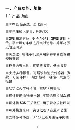
1.1 产品功能
■GSM 四频系统,全球通用
■宽电压输入范围:6-36V DC
■GPS 精准定位,支持 A-GPS,GPRS 定时上传,平台可对车辆进行实时追踪、并可将历史轨迹回放
■浏览器、智能手机客户端多种平台查询和短信查询
■设备内置电池,可剪线报警、低电报警
■支持多种报警,可增设加速度传感器(B
款,可选部件),增加振动、碰撞、跌落等报警
■ACC 点火信号检测,车辆状态提示
■可外接断油/电继电器,实现远程控制车辆
■可外接 SOS 开关按钮,用于紧急求救呼叫
■可外接麦克风,实现远程语音监听功能
■支持多种协议,GPRS 远程升级程序内核

2
1.2 产品规格
工作电压 12VDC/24VDC
工作电流 <30mA@12V
待机电流 <10mA@12V
GPS 定位精度 15 米
基站定位精度 100 米
GPS 频段 1575MHz
GSM 频段 850/900/1800/1900MHz
热/温/冷启动时间 <3 秒,<15 秒,<60 秒
内置电池 200mAh
外形尺寸,mm 79.5(L)X 38.5(W) X 10.5(H)
工作环境温度 -20℃~70℃
工作环境湿度 20%~80%RH
机器净重 45 g

3
二、产品结构、配件
2.1 产品结构
-机身正面(接收面)-
4
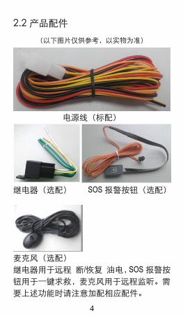
2.2 产品配件
(以下图片仅供参考,以实物为准)
电源线(标配)
继电器(选配) SOS 报警按钮(选配)
麦克风(选配)
继电器用于远程 断/恢复 油电,SOS 报警按
钮用于一键求救,麦克风用于远程监听。需
要上述功能时请注意加配相应配件。
5
三、安装 SIM 卡
3.1 安装前的准备
打开包装盒,检查设备型号是否正确,配件是否齐全,
否则请联络你的经销商;终端需要一张 GSM SIM 卡,
SIM 卡的选择请参考经销商的意见;
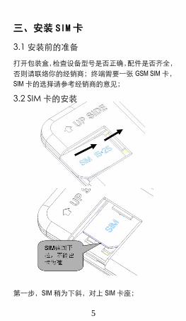
3.2 SIM 卡的安装
第一步,SIM 稍为下斜,对上 SIM 卡座;
6
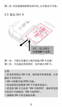
第二步,先往里插到底再往回平拉,以不能出卡为准。
3.3 取出 SIM 卡
第一步,于图示位置往上稍为抬起 SIM 卡边缘;
第二步,卡边越过壳体挡栏,往外拔出 SIM 卡。
注意:
●在安装或取出 SIM 卡前,请先断开终端电源,让机
器处于关机状态。
●SIM 卡需要开通 GPRS 功能。
●电话查询功能需要 SIM 卡开通来电显示。
●若您的 SIM 卡已启用“SIM 卡锁(PIN)”,请参考您的
手机用户手册取消“SIM 卡锁(PIN)”。
●请确保 SIM 卡有足够的余额。
7
四、终端安装
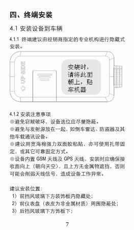
4.1 安装设备到车辆
4.1.1 终端建议由经销商指定的专业机构进行隐藏式
安装。
4.1.2 安装注意事项
●避免窃贼破坏,设备选位应尽量隐蔽。
●避免与发射源放在一起,如倒车雷达、防盗器及其
他车载通讯设备。
●建议用宽海棉强力双面胶粘贴,亦可使用扎带固
定,或其它可靠固定方式。
●设备内置 GSM 天线及 GPS 天线,安装时应确保接
收面向上(朝向天空),且上方无金属物遮挡,否则
可能会削弱天线信号,造成设备工作异常。
建议安装位置:
1)前挡风玻璃下方装饰板内隐藏处;
2)前仪表盘(表皮为非金属材质)周围隐蔽处;
3)后挡风玻璃下方饰板下;
8
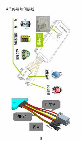
4.2 终端如何接线
9
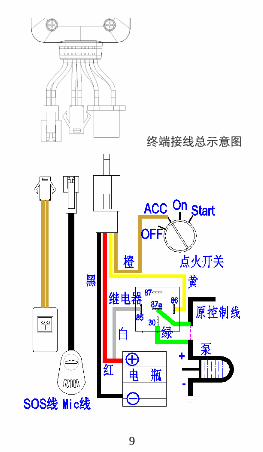
终端接线总示意图
10
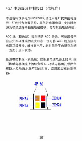
4.2.1 电源线及控制接口(依视向)
本设备标准供电为 6V-36VDC,请选用原厂提供的电源
线,红色线为电源正极,黑色为电源负极;安装时电
源负极请选择单独接地或搭铁,勿与其他地线共接。
ACC 线(橙色线)接车辆的 ACC 开关,可使服务平
台获知车辆准确的点火状态;也可将 ACC 线直接与
电源正极并接,维持高电平,此时服务平台识别车辆
一直处于点火状态。
断油电控制线(黄色线)接断油电继电器上的 86 端
(即继电器插座上的细黄线)。将继电器用扎带固定
在防水及地面水溅不到的地方;或用胶袋罩住继电
器。

11
4.2.2 外围接口(依视向)
12
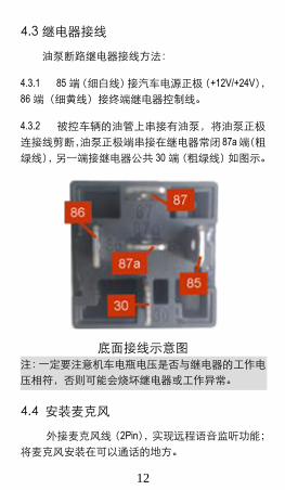
4.3 继电器接线
油泵断路继电器接线方法:
4.3.1 85 端(细白线)接汽车电源正极(+12V/+24V),
86 端(细黄线)接终端继电器控制线。
4.3.2 被控车辆的油管上串接有油泵,将油泵正极
连接线剪断,油泵正极端串接在继电器常闭 87a端(粗
绿线),另一端接继电器公共 30 端(粗绿线)如图示。
底面接线示意图
注:一定要注意机车电瓶电压是否与继电器的工作电
压相符,否则可能会烧坏继电器或工作异常。
4.4 安装麦克风
外接麦克风线(2Pin),实现远程语音监听功能;
将麦克风安装在可以通话的地方。

13
4.5 安装 SOS 求救按钮
外接 SOS 求救线(2Pin),用于紧急报警呼叫求
救。将薄膜开关粘贴在手可以操作到的地方。
五、开启/关闭终端
5.1 开机
开机:在终端插入有效的 SIM 卡,然后接好所
有的配线后,终端自动开机。
5.2 状态指示灯
终端自动搜索 GSM 网络信号时,红灯(GSM 指
示灯)为快闪;当搜到信号且正确登录运营商网络时,
红灯(GSM 指示灯)变为慢闪。
终端自动搜索 GPS 卫星信号时,蓝灯(GPS 指
示灯)为快闪;当搜到卫星信号且已经定位时,蓝灯
(GPS 指示灯)变为慢闪。
蓝灯/GPS
红灯/GSM
14
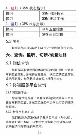
1、红灯(GSM 状态指示)
快闪 GSM 网络搜索
慢闪 GSM 正常工作
2、蓝灯(GPS 状态指示)
快闪 GPS 卫星搜索
慢闪 GPS 已经定位
5.3 关机
切断外部电源,取出 SIM 卡,一会终端自行关机。
六、查询、监听、切断/恢复油路
6.1 短信查询
您可编写位置查询短信发送至终端 SIM 卡获取
车辆位置信息,终端将回复最后一次定位的位置信息
或地图链接。短信格式请参见《操作指令》。
6.2 终端服务平台查询
6.2.1 浏览器平台
您可通过浏览器上网登录终端定位服务平台来
查看车辆的位置,终端定位服务平台网址可咨询您的
经销商。
6.2.2 智能手机客户端
我们已经为您准备好了安卓客户端(Android),
苹果客户端(iOS),以便您使用智能手机查询车辆,
安装包请向您的经销商索取。
15
注:请在您的经销商处获取服务平台的使用说明。
6.3 终端监听
6.3.1 打入监听
当设定的管理员号码(如中心号码、SOS 管理员
号码)拨打终端时,终端响铃 8 秒后会自动进入监听
状态,此时可对设备(车辆内部环境)进行监听。非
管理员号码拨打终端不能监听,此功能需设备号码开
通来电显示。
6.3.2 指令监听
发送监听指令给终端(参考《操作指令》),终端
会循环 3 次拨打指令中指定的号码,直到拨通为止,
拨通后被拨叫号码可对设备(车辆内部环境)进行监
听。
6.4 切断/恢复油路
6.4.1 切断油路
可由服务平台或管理员短信下发断油指令,在保
证车辆处于安全行驶的前提下,切断车辆的油路,达
到将车辆强行停止并无法启动车辆的目的。
为保证车辆安全,终端仅在 GPS 处于有效定位
状态,且满足车辆时速小于 20km/h 或车辆静止的条
件下才可执行断油操作。
6.4.2 恢复油路
可由服务平台或管理者短信下发恢复油路指令,
终端将执行恢复油路动作。
16
七、终端配置
请参考《操作指令》。
八、终端报警
8.1 振动报警(仅 B 款)
报警条件:当车辆发生振动时。
注:需要设定振动灵敏度和时间,有设防/撤防
开关。
8.2 碰撞/跌落报警(仅 B 款)
报警条件:当终端所处车辆发生碰撞、跌落时。
8.3 速度报警
报警条件:当车辆超过和低于设定速度时。
注:需要设置速度上限和速度下限。
8.4 电子围栏报警
报警条件:当车辆进/出/跨越电子围栏时。
注:需要设置围栏条件、围栏种类等等。
8.5 剪线报警
报警条件:当终端外接电源被切断时。

17
8.6 低电报警
报警条件:当终端外接电源被切断且内置电池电
量低于一定值。
8.7 SOS 报警
报警条件:当设备 SOS 键被长按3秒。
注:需配 SOS 按键(可选附件),并设置 SOS 管
理员号码。出警时终端将会循环 3 次拨打设定的管理
者号码,直到拨通为止。
注:当出现以上警情时,终端会向服务平台发出
报警,如果设备已经设置相应管理员号码,设备还将
向管理员号码发出报警短信。
注:8.1 和 8.2报警为 B款加配 加速度传感器 部
件后专属报警; 8.1、8.3、8.4 和 8.7 报警需设置相关
参数,设置详情见:《操作指令》
18
九、故障排除
9.1 无法连接服务平台
终端首次安装后,服务平台一直显示未上线。请
检查终端:
1)主电源接线是否正确,注意不要接到汽车内
部控制线。
2)SIM 卡是否正确安装,请参考安装说明。
3)检查 LED 指示灯状态,正常时,红色 GSM 状
态指示灯慢闪亮;蓝色 GPS 状态指示灯慢闪亮;
4)通过指令查询终端的参数,检查终端返回的
参数是否正确。
9.2 后台显示离线状态
首先观察设备指示灯是否正常,在没有条件观察
的情况下,可以先检查 SIM 卡的状态,步骤如下:
1)拨打设备的 SIM 卡号码,看是否能听到电话
接通的声音。
2)车辆是否在无 GSM 网络信号的地方。
3)观察掉线终端所处的区域内,是个别终端掉
线还是全部掉线,以判定是否为运营商网络问题。
4)SIM 卡是否欠费。
5)如果终端在月底最后一天离线,请检查 GPRS
业务是否被取消。
6)通过指令查询终端的参数,检查终端返回的
参数是否正确。
19
9.3 长时间不定位
若终端 GPS 功能已被激活,但又长时间不定位,
请检查终端:
1)车辆是否在无 GPS 卫星信号的地方
2)终端在安装时,应使接收面朝向天空。
3)终端安装位置上方必须是没有电磁波吸收的
物质(如金属)遮挡的地方,特别要注意终端所处位
置上方车辆玻璃不要贴防爆隔热膜(此膜成分中有较
高的金属成分,会吸收高频电磁波),否则 GPS 信号
会受到很大的影响导致定位精度下降,严重时会使终
端难以定位。
9.4 定位漂移严重
当 GPS 信号接收环境较差时(周边有高大建筑
遮挡 GPS 信号),会产生严重的定位漂移。此时请将
车开到空旷的地方准确定位。
9.5 指令接收异常
1)检查指令格式是否正确。
2)车辆是否在无 GSM 网络信号的地方。
3)检查终端的 SIM 卡是否正确安装。

20
十、保修细则
10.1 特别声明
1)若本产品日后有任何技术变更,恕不另行通
知。
2)产品外观、颜色如有改动,以实物为准。
3)保修卡只适应于下述所列 IMEI 号机子的三包
服务。
4)请妥善保管此保修卡,保修时请出示此卡及
原购买单据。
10.2 保修期
自购买之日起,非人为损坏故障主机保修一年。
10.3 售后服务
属下列情况之一的,不在保修范围,但可适当
付费维修;
(一)超过保修期限。
(二)未经我司授权,擅自拆卸或维修造成损坏。
(三)因安装、使用、维护、保管不当造成损坏的。
(四)产品 IMEI 号被撕去或模糊不清。
(五)保修凭证与产品型号不符或保修凭证被涂改。
(六)因不可抗力造成的损坏。
Welcome to use our terminal,please read this
manual carefully to install and operate the terminal exactly. This user manual is for reference only. If some contents and operation steps are inconsistent with those for the actual product, the latter will prevail.
Using TK116 GPS tracker, we can position、
monitor and control the vehicle on the position
server via GPRS、GPS and Internet. It can
help customers to manage transparently、
reduce cost、maintain security and raise
efficiency. Now it is widely used in business
traffic、logistics distribution、automobile lease、
intelligent transportation、shipping market、
army and police、rescuing、Safety
Supervision 、Intelligent city…

21
Ⅰ. Product Features
■Supports quad bands, i.e. 850/900/1800/1900MHz, universal in the world.
■Wide Input Voltage:6-36V DC.
■GPS precise positioning with A-GPS and uploaded by GPRS regularly, Supports real-time tracking and history track playback. ■Web browser platform, Smart phone app platform and SMS query. ■Built-in battery, Power disconnect alarm & Low battery alarm. ■Supports multiple alarm, acceleration sensor can be added (B models, optional component), so as increase vibration, collision and falling alarm. ■Supports ACC status checking and vehicle status notifying. ■Use relay to remotely control the vehicle. ■Use SOS button for SOS call. ■Use external MIC to remotely monitor. ■Multiple protocol support, OTA upgrade program.
22
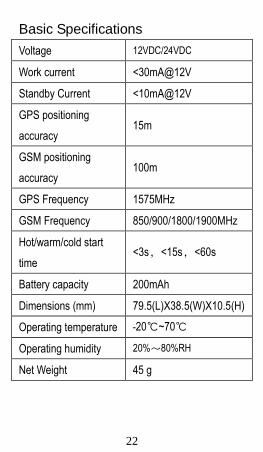
Basic Specifications
Voltage 12VDC/24VDC
Work current <30mA@12V
Standby Current <10mA@12V
GPS positioning
accuracy 15m
GSM positioning
accuracy 100m
GPS Frequency 1575MHz
GSM Frequency 850/900/1800/1900MHz
Hot/warm/cold start
time <3s,<15s,<60s
Battery capacity 200mAh
Dimensions (mm) 79.5(L)X38.5(W)X10.5(H)
Operating temperature -20℃~70℃
Operating humidity 20%~80%RH
Net Weight 45 g
23
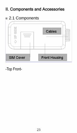
Ⅱ. Components and Accessories
■ 2.1 Components
-Top Front-

24
■ Accessories(reference pictures)
Power Cables(Fault)
Relay(Optional) SOS Cables(Optional)
Microphone(Optional)
Relay for remote cut off / resume oil, SOS button for SOS help, microphone for remote monitoring. Please note that these functions need the device equipped with the matched accessories.

25
Ⅲ. SIM card Installation
3.1 Before Installation
Open the packing case, then check if the terminal is OK and the accessories are intact, or please contact your dealer;
3.2 Install the SIM card
You need a suitable SIM card for using the terminal, please contact your dealer if you have any question;

26
1. Insert the SIM card until cannot move it inside anymore; 2. Pull the SIM card back a bit;
3.3 Uninstall the SIM card Lift up the edge of the SIM card, next pull it out.
1. Lift up the edge of the SIM card; 2. Pull out the SIM card. Note:
●Please cut off the power before installing or uninstalling the SIM card.
●The SIM card should support GPRS and the GPRS should be opening.
27
●Inquiry by call needs the SIM card supporting the calling line identification presentation.
●If you enable the PIN code of the SIM card, please use your mobile phone to disable the PIN code.
●Please make sure that the SIM card has sufficient balance.
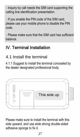
Ⅳ. Terminal Installation
4.1 Install the terminal
4.1.1 Suggest to install the terminal concealed by the dealer designated professional body.
Please make sure to install the terminal with this side upward, and use wide strong double-sided adhesive sponge to fix it.

28
Please make sure to install the terminal with this side towards the ground, and use wide strong double-sided adhesive sponge to fix it.
4.1.2 Installation Notice
●Hide the terminal properly inside the car body in order to avoid damages.
●Keep the terminal away from RF emission sources such as backing radar, car burglar alarm and other vehicle mounted communication devices.
●Suggest to use wide strong double-sided adhesive sponge to fix it, or use cable ties and other liable methods to fix it.
●Device Built-in GSM antenna and GPS antenna, Installation should ensure that the receiving side facing up (towards the sky) without metal cover on the top of it, otherwise may weaken the antenna signal, Cause the device to not work correctly.
The recommended installation location:
1)The hiding place below the front windshield trim
panel;
2)The hiding place around the front dash(if the
surface is not made of metal);
3)The place under the rear windshield;
29
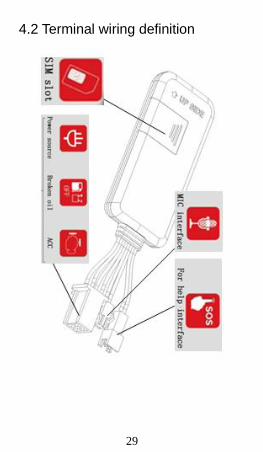
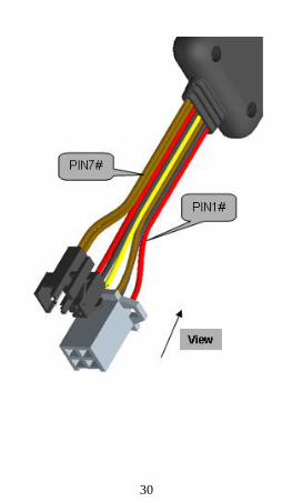
4.2 Terminal wiring definition
30

31
Total schematic wiring terminal
32
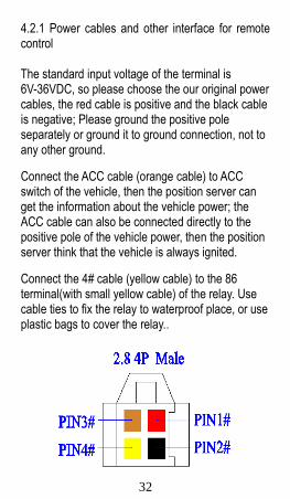
4.2.1 Power cables and other interface for remote control The standard input voltage of the terminal is 6V-36VDC, so please choose the our original power cables, the red cable is positive and the black cable is negative; Please ground the positive pole separately or ground it to ground connection, not to any other ground.
Connect the ACC cable (orange cable) to ACC switch of the vehicle, then the position server can get the information about the vehicle power; the ACC cable can also be connected directly to the positive pole of the vehicle power, then the position server think that the vehicle is always ignited.
Connect the 4# cable (yellow cable) to the 86 terminal(with small yellow cable) of the relay. Use cable ties to fix the relay to waterproof place, or use plastic bags to cover the relay..

33
4.2.2 Other accessories’ interfaces

34
4.3 Relay wiring
Relay wiring diagram shows how to wire the relay to control the fuel pump:
4.3.1 Connect the 85 terminal(with small white cable) to the positive pole of the vehicle power (+12V/+24V), connect the 86 terminal(with small yellow cable) to the 4# cable of the terminal.
4.3.2 Cut off the positive pole of the fuel pump, next serial connect the positive pole to the 87a terminal(with think green cable) of the relay, and connect another pole to 30 terminal(with think green cable), showing as in the figure.
Bottom of the relay Wiring Diagram
35
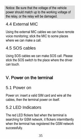
Notice: Be sure that the voltage of the vehicle power should match up to the working voltage of the relay, or the relay will be damaged.
4.4 External MIC
Using the external MIC cables we can have remote voice monitoring; stick the MIC to some places where we can make a call.
4.5 SOS cables
Using SOS cables we can make SOS call. Please stick the SOS switch to the place where the driver can touch.
Ⅴ. Power on the terminal
5.1 Power on
Power on: insert a valid SIM card and wire all the cables, then the terminal power on itself.
5.2 LED Indicators
The red LED flickers fast when the terminal is searching for GSM network, it flickers intermittently when the terminal has registered the GSM network successfully.
36
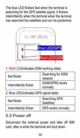
The blue LED flickers fast when the terminal is searching for the GPS satellite signal, it flickers intermittently when the terminal when the terminal has searched the satellites and can be positioned.
Blue LED/GPS
Red LED/GSM
1. Red LED(indicates GSM working state)
fast flicker Searching for GSM network
intermittently flicker GSM/GPRS works normally
2. Blue LED(indicates GPS signal state)
fast flicker Searching GPS Satellites
intermittently flicker GPS works normally
5.3 Power off
Disconnect the external power and take off SIM
card, after a while the terminal will shut down.
37
Ⅵ. Inquiry/Monitoring/Cut Oil
6.1 Inquiry by SMS
You can write a positioning SMS sending to the terminal to inquiry terminal position, the terminal will reply position SMS or map link. The SMS commands please refer to the Operation Commands
6.2 Inquiry by service platform
6.2.1 Web Browser platform You can login the service platform and enter your ID and password to check the position of the terminal. Please ask your dealer for the WWW address of the position service platform.
6.2.2 Smart phone applications platform
You can use a smart phone to check the terminal’s position. We have prepare for you the Android client (Android), Apple clients (IOS), please check with your dealer to get installation package.
6.3 Terminal Monitoring
6.3.1 Monitoring by dialing terminal When the setting administrator number (such as center number, SOS administrator number) dial the terminal, the terminal will automatically connect the call after 8 seconds ring . Non-administrators can not monitor terminal by dialing, and this feature
38
requires the terminal has the Caller ID.
6.3.2 Monitoring by Command
Sent monitor command to the terminal (see "Operating Instructions"), the terminal will cycle dial the number specified in the command for three times until getting through.
6.4 Cut off/Recover Oil circuits
6.4.1 Cut off oil circuits
The position server or the managers can send cut-off fuel commands when needed. The fuel of the vehicle will be cut off on the premise of safety, and the vehicle will not be powered on.
To make sure the safety of the vehicle, the fuel of the vehicle will be cut off only if the terminal has positioned by GPS and the speed of the vehicle is less than 20KM/h or the vehicle is not moving.
6.4.2 Recover oil circuits
The position server or the managers can send recover-fuel-circuit commands to the terminal when needed, the terminal will recover the fuel circuits of the vehicle.

39
Ⅶ. Set up the terminal
Please refer to the <Operation Commands>
Ⅷ. Terminal Alarm 8.1 Vibration Alarm(B type)
Conditions: When the Vehicle Vibration occurs. Note: You need to set vibration sensitivity and time, there are arm / disarm switch.
8.2 Collision / falling Alarm(B type)
Conditions: When the Vehicle Collision or falling occurs.
8.3 Speed Alarm
Conditions: When the vehicle over and below the set speed. Note: You need to set the low speed limit and high speed limit.
8.4 Geo-fence Alarm
Conditions: when the vehicle entry / exit / across the Geo-fence. Note: You need to set the conditions of crossing fence, fence types and so on.
40
8.5 Power disconnect Alarm
Conditions: When the device is disconnected from external Power.
8.6 Low battery Alarm
Conditions: When the device is disconnected from external Power and built-in battery power falls below a certain value .
8.7 SOS Alarm(need SOS Cable)
Conditions: When the SOS button is long pressed for 3 seconds. Note: SOS button must be installed(optional accessory), and SOS administrator number must be set. When the SOS alarm occurs ,Terminal will dial the set SOS administrator number 3 times until get through. Note: When above alarm occurs, the terminal will send alarm to service platform, meanwhile send a SMS message to the administrator number if the number is set. Note: 8.1 and 8.2 is the alarm for B type(add acceleration sensor component); alarm parameters must be set before work in 8.1, 8.3, 8,4 and 8.7, Please refer to the <Operation Commands>
41
Ⅸ. Trouble shooting
9.1 Cannot connect to the platform
The terminal is never online on the position server when installed at the first time. Please check the terminal:
1)If the power cables are wired correctly? Pay
attention to not connect them to the controlling cables of the vehicle.
2)If the SIM card is installed correctly? Please refer
to the installation instructions.
3)Check the status of the LED indicators. If the
terminal is OK, the red LED and the blue LED will intermittently flick.
4)Inquiry the parameters of terminal via commands
and check the accuracy of the parameters.
9.2 Offline status on the platform
First check if the LED indicators are OK, if cannot check them, you can check the SIM card following next steps:
1)call the SIM card of the terminal and check if you
can hear the connecting ring.

42
2)Check if the vehicle is in the area where there is
no GSM signal.
3)Check if one terminal or all terminals are offline
in the area where terminal is offline. If all terminals are offline, you should ask the network operator If the network is OK.
4)Check if the SIM card has enough balance.
5)If the terminal becomes offline on the last day of
one month, please check GPRS is closed or not.
6)Inquiry the parameters of terminal via commands
and check the accuracy of the parameters.
9.3 Not positioning for a long time
If the GPS is active, but the terminal cannot be positioned for long time, please check the terminal:
1)If the vehicle is in the place where there is no
GPS signal.
2)The upside of the terminal should be installed
with face toward the sky.
3)The GSM and GPS signal may be weakened if
the terminal is installed in the place with electromagnetic wave absorption material(such as
43
metal blocks), special attention should be paid if there is metal thermal insulation layer or heating layer on the front windshield, so that the position accuracy will decline, and the severe ones will not be positioned.
9.4 Position drift
Serious position drift will be found in places where GPS signal is poor. Please drive the vehicle to the open places.
9.5 Commands receiving abnormally
1)Check the commands format.
2)Check if the vehicle is in the places where there
is GSM signal.
3)Check if the SIM card is properly installed.
Ⅹ. Warranty rules
10.1 Special statement
1)Technology change without notice.
2) If the color and appearance are inconsistent with those for the actual product, the latter will prevail.
44
3)Warranty card is only valid for the terminals with
the following IMEI.
4)Please take care of the warranty card and show
it with the original purchase receipts when enjoying the warranty service.
10.2 Warranty period
Since the date of purchase, passive waste host has one year warranty.
10.3 After sales
Any of the following circumstances not covered by the warranty, but may be appropriate to pay repair: 1)More than the warranty period.
2)Unauthorized removal or repair damaged.
3)Damage caused by improper installation, use,
maintenance, custody.
4)The IMEI label is torn or Obscure.
5)Warranty certificate and product models do not
match or warranty certificate be altered.
6)Damage caused by force majeure.
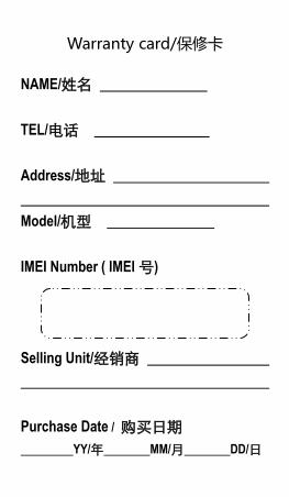
Warranty card/保修卡
NAME/姓名
TEL/电话
Address/地址
Model/机型
IMEI Number ( IMEI 号)
Selling Unit/经销商
Purchase Date / 购买日期
YY/年 MM/月 DD/日

Main
ten
an
ce
reco
rds
/ 维修记录
En
gin
eer
维修人员
Co
mp
leti
on
Dat
e
完成日期
Rec
ord
s
维修记录
Des
crip
tio
n
故障描述
Dat
e
日期


![GENERALITES GSM GPRS [Mode de compatibilité].pdf](https://img.pdfslide.tips/doc/110x75/55cf85e0550346484b92524b/generalites-gsm-gprs-mode-de-compatibilitepdf.jpg)
