Embed Size (px)
Citation preview

FR-S500E
Frequency Inverter
Instruction Manual(Basic)
FR-S520SE-0.2K to 1.5K-EC,FR-S540E-0.4K – 3.7K-EC
INDUSTRIAL AUTOMATIONMITSUBISHI ELECTRIC
MITSUBISHI ELECTRIC
Art. no.: 16047101 09 2004IB(NA)-0600210ENGVersion A


FR-S540E-0.4K to 3.7K-ECFR-S520SE-0.2K to 1.5K-EC
1
2
3
4
5
6
7
8
9
HEAD OFFICE:MITSUBISHI DENKI BLDG MARUNOUCHI TOKYO 100-8310
FR-S
500E-EC
TRA
NSISTO
RIZED
INVER
TERIN
STRU
CTIO
N M
AN
UA
L (BA
SIC)
A
TRANSISTORIZED INVERTER
FR-S500INSTRUCTION MANUAL (BASIC)
CONTENTSCONNECTION OF PERIPHERAL DEVICES ............................................. 21.1 Basic configuration ...................................................................................... 2
INSTALLATION METHOD.......................................................................... 42.1 Installation of the inverter............................................................................. 4
SPECIFICATIONS OF WIRING AND TERMINALS ................................... 53.1 Terminal connection diagram ...................................................................... 53.2 Main circuit................................................................................................... 63.3 Control circuit............................................................................................... 9
RUN AND OPERATION............................................................................ 144.1 Setting the frequency to perform operation
(example: performing operation at 30Hz) ................................................. 164.2 Using the setting dial like a potentiometer to perform operation................ 174.3 Setting the parameters .............................................................................. 184.4 Clearing the parameters ............................................................................ 204.5 Monitoring the output current..................................................................... 214.6 Adjusting the current amount for frequency setting signal (example:
performing operation at 30Hz) .................................................................. 22ADJUSTMENT OF THE FREQUENCY SETTING POTENTIOMETER AND INDICATOR...................................................... 245.1 Changing the output frequency setting of the frequency setting potentiometer
(bias and gain of frequency setting voltage (current)) .............................. 255.2 Adjustment (calibration) of the frequency meter (indicator) ....................... 28
FUNCTION LIST ....................................................................................... 296.1 Basic function parameter list...................................................................... 296.2 Explanation of the basic function parameters............................................ 306.3 Extended function parameter list ............................................................... 32
ERRORS AND PROTECTIVE FUNCTIONS ............................................ 457.1 About errors (definitions) ........................................................................... 457.2 To know the operating status at the occurrence of alarm
(only when FR-PU04 is used).................................................................. 487.3 Correspondence between digital and actual characters............................ 487.4 Resetting the inverter................................................................................. 487.5 Troubleshooting ......................................................................................... 497.6 Precautions for maintenance and inspection............................................. 52
SPECIFICATIONS .................................................................................... 638.1 Ratings....................................................................................................... 638.2 Common specifications.............................................................................. 65
OUTLINE DRAWINGS.............................................................................. 67Appendix 1 Instructions for compliance with the European Directive 70Appendix 2 Instructions for UL and cUL.............................................. 72
Thank you for choosing this Mitsubishi transistorized inverter.If this is the first time for you to use the FR-S500 series, please read through this instruction manual (basic)carefully and use the inverter safely.If you are going to use the inverter for higher-level applications, the FR-S500 instruction manual (detailed)[IB(NA)-0600211ENG] is separately available from where you purchased the inverter or a Mitsubishi salesrepresentative.
IB(NA)-0600210ENG-A (0409) MDOC Printed in Japan Specifications subject to change without notice.
123
4
5
6
7
8
9

A-1
1. Electric Shock Prevention
This instruction manual (basic) provides handling information and precautions for useof the equipment.Please forward this instruction manual (basic) to the end user.
This section is specifically about safety mattersDo not attempt to install, operate, maintain or inspect the inverter until you have readthrough this instruction manual (basic) and appended documents carefully and canuse the equipment correctly. Do not use the inverter until you have a full knowledgeof the equipment, safety information and instructions.In this instruction manual (basic), the safety instruction levels are classified into"WARNING" and "CAUTION".
Assumes that incorrect handling may cause hazardousconditions, resulting in death or severe injury.Assumes that incorrect handling may cause hazardousconditions, resulting in medium or slight injury, or may causephysical damage only.
Note that even the level may lead to a serious consequenceaccording to conditions. Please follow the instructions of both levels because they areimportant to personnel safety.
WARNING While power is on or when the inverter is running, do not open the front cover. You
may get an electric shock. Do not run the inverter with the front cover or wiring cover removed. Otherwise,
you may access the exposed high-voltage terminals or the charging part of thecircuitry and get an electric shock. Also, the inverter's ability to withstandearthquakes will deteriorate.
Even if power is off, do not remove the front cover except for wiring or periodicinspection. You may access the charged inverter circuits and get an electric shock.
Before starting wiring or inspection, check to make sure that the 3-digit LED invertermonitor is off, wait for at least 10 minutes after the power supply has been switchedoff, and check to make sure that there are no residual voltage using a tester or thelike.
This inverter must be earthed. Earthing must conform to the requirements ofnational and local safety regulations and electrical codes. (JIS, NEC section 250,IEC 536 class 1 and other applicable standards)
Any person who is involved in the wiring or inspection of this equipment should befully competent to do the work.
Always install the inverter before wiring. Otherwise, you may get an electric shockor be injured.
Perform setting dial and key operations with dry hands to prevent an electricshock.
Do not subject the cables to scratches, excessive stress, heavy loads or pinching.Otherwise, you may get an electric shock.
Do not change the cooling fan while power is on. It is dangerous to change thecooling fan while power is on.
When you have removed the front cover, do not touch the connector above the 3-digit monitor LED display. Otherwise, you get an electrick shock.
WARNING
CAUTION
CAUTION

A-2
2. Fire Prevention
3. Injury Prevention
4. Additional InstructionsAlso note the following points to prevent an accidental failure, injury, electric shock,etc.
(1) Transportation and installation
CAUTION Mount the inverter on an incombustible surface. Installing the inverter directly on or near
a combustible surface could lead to a fire. If the inverter has become faulty, switch off the inverter power. A continuous flow of
large current could cause a fire. Do not connect a resistor directly to the DC terminals +, -. This could cause a fire.
CAUTION Apply only the voltage specified in the instruction manual to each terminal to
prevent damage, etc. Always connect to the correct terminal to prevent damage, etc. Always make sure that polarity is correct to prevent damage, etc. While power is on or for some time after power-off, do not touch the inverter as it is
hot and you may get burnt.
CAUTION When carrying products, use correct lifting gear to prevent injury. Do not stack the inverter boxes higher than the number recommended. Ensure that installation position and material can withstand the weight of the
inverter. Install according to the information in the instruction manual. Do not install or operate if the inverter is damaged or has parts missing. When carrying the inverter, do not hold it by the front cover or setting dial; it may
fall off or fail. Do not stand or rest heavy objects on the inverter. Check the inverter mounting orientation is correct. Prevent other conductive bodies as screws and metal fragments or other
flammable substance as oil from entering the inverter. As the inverter is a precision instrument, do not drop or subject it to impact. Use the inverter under the following environmental conditions: This could cause
the inverter damage.
*Temperatures applicable for a short time, e.g. in transit.
Env
ironm
ent
Ambient Temperature -10°C to +50°C (non-freezing)
Ambient humidity 90%RH maximum (non-condensing)Storagetemperature -20°C to +65°C *
Atmosphere Indoors (free from corrosive gas, flammable gas, oil mist,dust and dirt)
Altitude/vibration
Maximum 1000m above sea level for standard operation.After that derate by 3% for every extra 500m up to 2500m(91%). 5.9m/s2 or less (conforming to JIS C 60068-2-6)
A-3
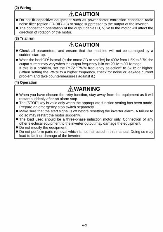
(2) Wiring
(3) Trial run
(4) Operation
CAUTION Do not fit capacitive equipment such as power factor correction capacitor, radio
noise filter (option FR-BIF(-H)) or surge suppressor to the output of the inverter. The connection orientation of the output cables U, V, W to the motor will affect the
direction of rotation of the motor.
CAUTION Check all parameters, and ensure that the machine will not be damaged by a
sudden start-up. When the load GD2 is small (at the motor GD or smaller) for 400V from 1.5K to 3.7K, the
output current may vary when the output frequency is in the 20Hz to 30Hz range.If this is a problem, set the Pr.72 "PWM frequency selection" to 6kHz or higher.(When setting the PWM to a higher frequency, check for noise or leakage currentproblem and take countermeasures against it.)
WARNING When you have chosen the retry function, stay away from the equipment as it will
restart suddenly after an alarm stop. The [STOP] key is valid only when the appropriate function setting has been made.
Prepare an emergency stop switch separately. Make sure that the start signal is off before resetting the inverter alarm. A failure to
do so may restart the motor suddenly. The load used should be a three-phase induction motor only. Connection of any
other electrical equipment to the inverter output may damage the equipment. Do not modify the equipment. Do not perform parts removal which is not instructed in this manual. Doing so may
lead to fault or damage of the inverter.

A-4
(5) Emergency stop
(6) Maintenance, inspection and parts replacement
(7) Disposing of the inverter
(8) General instructions
CAUTION The electronic thermal relay function does not guarantee protection of the motor
from overheating. Do not use a magnetic contactor on the inverter input for frequent starting/stopping
of the inverter. Use a noise filter to reduce the effect of electromagnetic interference. Otherwise
nearby electronic equipment may be affected. Take measures to suppress harmonics. Otherwise power supply harmonics from
the inverter may heat/damage the power capacitor and generator. When a 400V class motor is inverter-driven, please use an insulation-enhanced
motor or measures taken to suppress surge voltages. Surge voltages attributable tothe wiring constants may occur at the motor terminals, deteriorating the insulation ofthe motor.
When parameter clear or all clear is performed, reset the required parametersbefore starting operations. Each parameter returns to the factory setting.
The inverter can be easily set for high-speed operation. Before changing itssetting, fully examine the performances of the motor and machine.
In addition to the inverter's holding function, install a holding device to ensure safety. Before running an inverter which had been stored for a long period, always
perform inspection and test operation.
CAUTION Provide a safety backup such as an emergency brake which will prevent the
machine and equipment from hazardous conditions if the inverter fails.When the breaker on the inverter primary side trips, check for the wiring fault (short
circuit), damage to internal parts of the inverter, etc. Identify the cause of the trip,then remove the cause and power on the breaker.
When any protective function is activated, take the appropriate corrective action,then reset the inverter, and resume operation.
CAUTION Do not carry out a megger (insulation resistance) test on the control circuit of the
inverter.
CAUTION Treat as industrial waste.
Many of the diagrams and drawings in this instruction manual (basic) show the inverterwithout a cover, or partially open. Never operate the inverter in this manner. Always replacethe cover and follow this instruction manual (basic) when operating the inverter.

1
Unpack the inverter and check the capacity plate on the front cover and the ratingplate on the inverter side face to ensure that the product agrees with your order andthe inverter is intact.
Product Checking and Parts Identification
Removal and reinstallation of thefront coverRemove the front cover by pulling ittoward you in the direction of arrow.To reinstall, match the cover to theinverter front and install it straight.
Removal and reinstallation of the wiring cover The cover can be removed easily by pulling it towardyou.To reinstall, fit the cover to the inverter along the guides.
RS-485 communication connectorWhen using the RS-485 connector to wire the cable, youcan cut off the tab of the wiring cover to wire it. (Cutting offthe tab will provide protective structure IP10.)
CAUTIONThe connector above the operation panel is formanufacturer use. Do not touch it as doing so maycause an electric shock.
Parts and name plate
Front cover
Wiring cover
Input rating
Output rating
Serial number
Rating plate
Inverter type
FR - S540E - K - EC0.4
Inverter type Serial number Inverter type
Inverter capacity "kW"
Symbol Voltage class
S540E Three-phase 400V class
S520SE Single-phase 200V class
Capacity plate
Operation panelFR-S540E-0.4K-EC
FR-S540E-0.4K-EC XXXXXX
FR-S520SE-0.2K to 0.75K-EC FR-S540E-0.4K to 3.7K-EC
FR-S520SE-1.5K-EC
Wiring cover
Tab

2
Basic configuration
1. CONNECTION OF PERIPHERAL DEVICES
1.1 Basic configurationPower supplyUse within the permissible power supply specifications of the inverter. (Refer to page 63.)
No-fuse breaker or earth leakage circuit breakerThe breaker must be selected carefully since an in-rush current flows in the inverter at power on.Magnetic contactorInstall for your safety. Do not use this magnetic contactor to start and stop the inverter. Doing so will cause the inverter life to be shorten. (Refer to page 13.)
Installation of a reactorA reactor must be used when the power factor is to be improved or the inverter is installed near a large supply system (500kVA or more and wiring distance within 10 m). Make the selection carefully.
Devices connected to the outputDo not install a power factor correction capacitor,surge suppressor or radio noise filter on the outputside of the inverter. When installing a no-fuse breaker on the output side of the inverter, contact each manufacturer for selection of the no-fuse breaker.EarthTo prevent an electric shock, always earth the motorand inverter. For reduction of induction noise from the power lineof the inverter, it is recommended to wire the earthcable by returning it to the earth terminal of theinverter.(For details of noise reduction techniques, refer to the instruction manual (detailed).)
(MC)
(NFB)
or (ELB)
AC reactor
(FR-BAL)
DC reactor
(FR-BEL)
Earth
Earth
InverterThe life of the inverter is influenced by ambient temperature. Check the ambient temperature. Epecially when mounting the inverter inside an enclosure, take cautions of the ambient temperature. (Refer to page 66.) Wrong wiring might lead to damage of the inverter.The control signal wires must be kept fully awayfrom the main circuit to protect them from noise.(Refer to page 5.)

3
1
CO
NN
ECTI
ON
OF
PER
IPH
ERA
L D
EVIC
ES
Basic configuration
1) Three-phase 400V power input
2) Single-phase 200V power input
*2. For installations in the United States or Canada, the circuit breaker must be inversetime or instantaneous trip type.
*3. The power factor may be slightly lower.*4. When the breaker on the inverter primary side trips, check for the wiring fault (short
circuit), damage to internal parts of the inverter, etc. Identify the cause of the trip,then remove the cause and power on the breaker.
Selection of peripheral devices (selection changes with the power inputspecifications of the inverter)
MotorOutput
(kW)
Applied Inverter Type
No-fuse Breaker (NFB *1, 4) orEarth Leakage Circuit Breaker
(ELB) (*2, 4)
Magnetic Contactor
(MC)(Refer to page 13)
Power Factor Improving AC
Reactor
Power Factor Improving DC
Reactor
0.4 FR-S540E-0.4K-EC 30AF/5A S-N10 FR-BAL-H0.4K
FR-BEL-H0.4K
0.75 FR-S540E-0.75K-EC 30AF/5A S-N10 FR-BAL-H0.75K
FR-BEL-H0.75K
1.5 FR-S540E-1.5K-EC 30AF/10A S-N10 FR-BAL-H1.5K
FR-BEL-H1.5K
2.2 FR-S540E-2.2K-EC 30AF/15A S-N10 FR-BAL-H2.2K
FR-BEL-H2.2K
3.7 FR-S540E-3.7K-EC 30AF/20A S-N20, S-N21
FR-BAL-H3.7K
FR-BEL-H3.7K
Motor Output
(kW)
Applied Inverter Type
No-fuse Breaker (NFB *1, 4) orEarth Leakage Circuit Breaker
(ELB) (*2, 4)
Magnetic Contactor
(MC)(Refer to page 13)
Power Factor Improving AC Reactor (*3)
Power Factor Improving DC Reactor (*3)
0.2 FR-S520SE-0.2K-EC 30AF/10A S-N10 FR-BAL-0.4K FR-BEL-0.4K
0.4 FR-S520SE-0.4K-EC 30AF/10A S-N20, S-N21 FR-BAL-0.75K FR-BEL-0.75K
0.75 FR-S520SE-0.75K-EC 30AF/15A S-N20, S-N21 FR-BAL-1.5K FR-BEL-1.5K
1.5 FR-S520SE-1.5K-EC 30AF/20A S-N20, S-N21 FR-BAL-2.2K FR-BEL-2.2K
*1. •Select the NFB according to the inverter powersupply capacity.
•Install one NFB per inverter.INV
NFB INV
IM
IM
NFB

4
Installation of the inverter
2. INSTALLATION METHOD2.1 Installation of the inverter
Install the inverter under the following conditions.
Inverter consists of precision mechanical and electronic parts. Never install orhandle it in any of the following conditions as doing so could cause an operationfault or failure.
When containing two or more
inverters, install them in parallel
and provide cooling measures.Leave enough clearances
and provide cooling measures.
Enclosure surface mounting Encasing multiple inverters
Fix the front
cover and wiring
cover after
removing them.
Vertical mounting
Vertical
Ambient temperature and humidity Clearances
These clearances are also
necessary for changing the
cooling fan. (The 1.5K or
more is provided with a
cooling fan.)Measurement position
5cm5cm
Measurementposition
5cm
Inverter
Temperature: -10°C to 50°C
Humidity: 90%RH maximum
10cm or more1cm
or more
10cm or more
1cm or more
Direct sunlightVibration(5.9m/s2 or more)
High temperature,high humidity
Oil mist, flammablegas, corrosive gas,fluff, dust, etc.
Horizontal placement
Transportationby holding frontcover or dial
Vertical mounting(when mounted inside enclosure)
Mounting to combustible material

5
Terminal connection diagram
3
SPEC
IFIC
ATI
ON
S O
F W
IRIN
G A
ND
TER
MIN
ALS
3. SPECIFICATIONS OF WIRING AND TERMINALS3.1 Terminal connection diagram Three-phase 400V power input
REMARKS*1. You can switch the position of sink and source logic. Refer to the instruction manual (detailed) for details.*2. When the setting potentiometer is used frequently, use a 2W1kΩ potentiometer.*3. The terminal functions change with input terminal function selection (Pr. 60 to Pr. 63). (Refer to page 36.)
(RES, RL, RM, RH, RT, AU, STOP, MRS, OH, REX, JOG, X14, X16, (STR) signal selection)*4. The terminal function changes according to the setting of output terminal function selection (Pr. 64, Pr. 65).
(Refer to page 37.) (RUN, SU, OL, FU, RY, Y12, Y13, FDN, FUP, RL, Y93, Y95, LF, ABC signal selection)
CAUTIONTo prevent a malfunction due to noise, keep the signal cables more than 10cm awayfrom the power cables.
InverterMotor
IMUVW
RUN
SE
Running
Alarm output
Operation status
output
Open collector
Open collector
outputs
A
B
C
Frequency setting potentiometer
1/2W1kΩ
Frequency setting signals (Analog)
10
22
3
1
4 to 20mADC(+) 4
0 to 5VDC
0 to 10VDC
5Current input(-)
(+5V)
(Common)
(4 to 20mADC)
Selected
output common
Low speed RL
NFB MC
Power factor improvingDC reactor(FR-BEL: Option)
Jumper: Remove this jumper when FR-BELis connected.
P1
SINK
SOURCE
Multi-speed
selection
Take care not to short terminals PC-SD.
RS-485 Connector
Three-phase AC power supply
Control circuit terminalMain circuit terminal
When using the current input as the frequency setting signal, set "4" in any of Pr. 60 to Pr. 63 (inputterminal function selection), assign AU (current input selection) to anyof terminals RH, RM, RL and STR and turn on the AU signal.
Control input
signals
(No voltage
input allowed)
STF
STR
RM
Forward rotation start
Reverse rotation start
Middle speed
High speed RH
Earth
SD
PC
External transistor common
Contact input common (sink)
Contact input common
24VDC power supply
AM
5
(+)
(-)
Analog signal output(0 to 5VDC)
Earth
*3
*1
*3
*3
*3
*4
*4
*4
*4
*2
L1L2L3
+
-

6
Main circuit
Single-phase 200V power input
3.2 Main circuit
3.2.1 Explanation of main circuit terminals
REMARKS•To ensure safety, connect the power input to the inverter via a magnetic contactor and earth leakage
circuit breaker or no-fuse breaker, and use the magnetic contactor to switch power on-off.•The output is three-phase 200V.
Terminal Symbol Terminal Name Description
L1, L2, L3 (*1) AC power input Connect to the commercial power supply.U, V, W Inverter output Connect a three-phase squirrel-cage motor.
+, − Brake unit connection
Connect the brake unit (BU), power regeneration common converter (FR-CV) or high power factor converter (FR-HC).
+, P1
Power factor improving DC
reactor connection
Remove the jumper across terminals + - P1 and connect the optional power factor improving DC reactor (FR-BEL(-H)).
Earth For earthing the inverter chassis. Must be earthed.
*1. When using single-phase power input, terminals are L1 and N.
NFB
IMUVW
MCPower
supply
Motor
Earth
NL1
7
Main circuit
3
SPEC
IFIC
ATI
ON
S O
F W
IRIN
G A
ND
TER
MIN
ALS
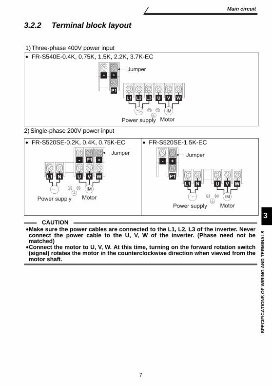
3.2.2 Terminal block layout
2)Single-phase 200V power input
1)Three-phase 400V power input• FR-S540E-0.4K, 0.75K, 1.5K, 2.2K, 3.7K-EC
• FR-S520SE-0.2K, 0.4K, 0.75K-EC • FR-S520SE-1.5K-EC
CAUTION•Make sure the power cables are connected to the L1, L2, L3 of the inverter. Neverconnect the power cable to the U, V, W of the inverter. (Phase need not bematched)•Connect the motor to U, V, W. At this time, turning on the forward rotation switch(signal) rotates the motor in the counterclockwise direction when viewed from themotor shaft.
P1
Jumper
Power supply Motor
U V W
IM
+
L1 L2 L3
-
P1
Motor
Jumper
U V W
IM
Power supply
L1 N
+-
P1
Jumper
Motor
U V W
IM
Power supply
+-
L1 N
8
Main circuit
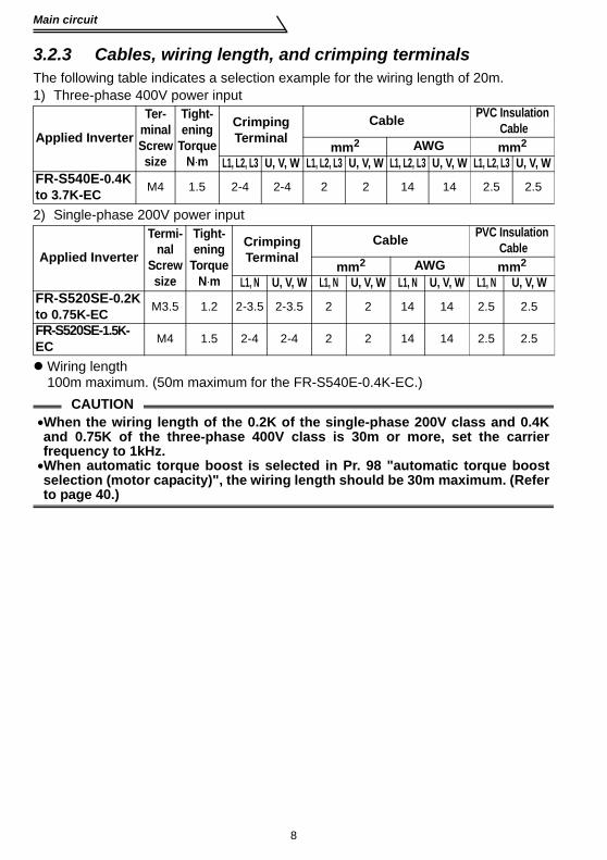
3.2.3 Cables, wiring length, and crimping terminalsThe following table indicates a selection example for the wiring length of 20m. 1) Three-phase 400V power input
2) Single-phase 200V power input
Wiring length100m maximum. (50m maximum for the FR-S540E-0.4K-EC.)
Applied Inverter
Ter-minalScrewsize
Tight-ening
TorqueN⋅m
Crimping Terminal
Cable PVC Insulation Cable
mm2 AWG mm2
L1, L2, L3 U, V, W L1, L2, L3 U, V, W L1, L2, L3 U, V, W L1, L2, L3 U, V, WFR-S540E-0.4K to 3.7K-EC M4 1.5 2-4 2-4 2 2 14 14 2.5 2.5
Applied Inverter
Termi-nal
Screwsize
Tight-ening
TorqueN⋅m
Crimping Terminal
Cable PVC Insulation Cable
mm2 AWG mm2
L1, N U, V, W L1, N U, V, W L1, N U, V, W L1, N U, V, WFR-S520SE-0.2K to 0.75K-EC M3.5 1.2 2-3.5 2-3.5 2 2 14 14 2.5 2.5
FR-S520SE-1.5K-EC M4 1.5 2-4 2-4 2 2 14 14 2.5 2.5
CAUTION•When the wiring length of the 0.2K of the single-phase 200V class and 0.4Kand 0.75K of the three-phase 400V class is 30m or more, set the carrierfrequency to 1kHz.•When automatic torque boost is selected in Pr. 98 "automatic torque boostselection (motor capacity)", the wiring length should be 30m maximum. (Referto page 40.)

9
Control circuit
3
SPEC
IFIC
ATI
ON
S O
F W
IRIN
G A
ND
TER
MIN
ALS
3.3 Control circuit3.3.1 Explanation of control circuit terminals
Symbol Terminal Name Definition
Inpu
t sig
nals
Con
tact
inpu
t
STF Forward rotation start
Turn on the STF signal to start forward rotation and turn it off to stop.
When the STF and STR signals are turned on simultaneously, the stop command is given.
STR Reverse rotation start
Turn on the STR signal to start reverse rotation and turn it off to stop. The terminal
functions change with input terminal function selection (Pr. 60 to Pr.63).(*3)
RHRMRL
Multi-speed selection
Turn on the RH, RM and RL signals in appropriate combinations to select multiple speeds.The priorities of the speed commands are in order of jog, multi-speed setting (RH, RM, RL, REX) and AU.
SD(*1)
External transistor common, Contact input common (sink)
When connecting the transistor output (open collector output), such as a programmable controller (PLC), connect the negative external power supply for transistor output to this terminal to prevent a malfunction caused by undesirable currents.(*6)When sink logic has been selected, this terminal serves as a contact input common.
PC(*1)
24VDC power supply, Contact input common(source)
Common to the contact input terminals (STF, STR, RH, RM, RL).This terminal can be used as a 0.1A 24VDC power supply across terminals PC-SD.
10 Frequency setting power supply 5VDC, Permissible load current 10mA.
Freq
uenc
y se
tting
2 Frequency setting (voltage signal)
Inputting 0 to 5VDC (or 0 to 10V) provides the maximum output frequency at 5V (10V) and makes input and output proportional. Switch between 5V and 10V using Pr. 73 "0-5V, 0-10V selection".Input resistance 10kΩ. Maximum permissible input voltage 20V
4 Frequency setting (current signal)
Input 4 to 20mADC. It is factory set at 0Hz for 4mA and at 50Hz for 20mA.Maximum permissible input current 30mA. Input resistance approximately 250Ω.Turn ON signal AU for current input.Turning the AU signal on makes voltage input invalid. Use any of Pr. 60 to Pr. 63 (input terminal function selection) to set the AU signal.
5 Frequency setting input common
Common terminal for the frequency setting signals (terminal 2, 4) and indicator connection (terminal AM). (*6)

10
Control circuit
*1. Do not connect terminals SD and PC each other or to the earth.For source logic (factory setting), terminal PC acts as the common terminal of contactinput. For sink logic, terminal SD acts as the common terminal of contact input. (Refer tothe separately available instruction manual (detailed) for switching method.)
*2. Low indicates that the open collector output transistor is on (conducts). High indicatesthat the transistor is off (does not conduct).
*3. RL, RM, RH, RT, AU, STOP, MRS, OH, REX, JOG, RES, X14, X16, (STR) signalselection (Refer to page 36.)
*4. RUN, SU, OL, FU, RY, Y12, Y13, FDN, FUP, RL, Y93, Y95, LF, ABC signal selection(Refer to page 37.)
*5. To be compliant with the European Directive (Low Voltage Directive), the operatingcapacity of relay outputs (A, B, C) should be 30VDC 0.3A.
*6. Terminals SD, SE and 5 are isolated from each other. Do not earth.
Out
put s
igna
ls
ABC
Alarm output
Changeover contact output indicates that the inverter protective function has activated and the output stopped. 230VAC 0.3A, 30VDC 0.3A. Alarm: discontinuity across B-C (continuity across A-C), Normal: continuity across B-C (discontinuity across A-C).(*5)
The function of the terminals changes according to the output terminal function selection (Pr. 64, Pr.65).(*4)
Ope
n co
llect
or
RUN Inverterrunning
Switched low when the inverter output frequency is equal to or higher than the starting frequency (factory set to 0.5Hz variable). Switched high during stop or DC injection brake operation. (*2) Permissible load 24VDC 0.1A (a voltage drop is 3.4V maximum when the signal is on)
SE Open collector common Common terminal for inverter running terminal RUN. (*6)
Indi
cato
r
AM Analog signal output
The output signal across terminals AM-5 is factory set to about 5VDC at 50Hz and is proportional to the corresponding output frequency. Frequency permissible load current 1mAOutput signal 0 to 5VDC
Com
mun
icat
ion
—— RS-485connector
Using the parameter unit connection cable (FR-CB201 to 205), the parameter unit (FR-PU04) can be connected.Communication operation can be performed using RS-485.For details of RS-485 communication, refer to the separately available instruction manual (detailed).
Symbol Terminal Name Definition

11
Control circuit
3
SPEC
IFIC
ATI
ON
S O
F W
IRIN
G A
ND
TER
MIN
ALS
3.3.2 Arrangement and wiring of control circuit terminals
Con
trol c
ircui
t ter
min
al b
lock
Loosen the terminal screw and insert the cable into the terminal.
Screw size: M3 (A, B, C terminals), M2 (other than the above)
Tightening torque: 0.5N•m to 0.6N•m (A, B, C terminals)0.22N•m to 0.25N•m (other than the above)
Cable size: 0.3mm2 to 0.75mm2
Screwdriver: Small flat-blade screwdriverTip thickness: 0.4mmTip width: 2.5mm
CAUTIONWhen using the bar terminal (without insulation sleeve), use care so that thetwisted wires do not come out.
PC
A B
SE RUN 10 2 5 4
SD STF STR RM RHSD
C
RL AM
CAUTIONUndertightening can cause cable disconnection or malfunction. Overtightening can cause a short circuit or malfunction due to damage to the screw or unit.
Cable stripping size
Wire the stripped cable after twisting it to prevent it from becoming loose.In addition, do not solder it.
ABC terminals 6mm
Other than the above 5mm
12
Control circuit
3.3.3 Connection to RS-485 connector(1) When connecting the parameter unit
Use the optional FR-CB2 . When the parameter unit (FR-PU04) is used,operation from the operation panel is not accepted. ( is valid)
(2) RS-485 communicationUsing the RS-485 connector, you can perform communication operation from apersonal computer etc. By connecting the RS-485 connector to computers suchas personal computer and FA with a communication cable, you can run/monitorthe inverter and read/write parameter values using a user program. For furtherdetails, refer to the instruction manual (detailed).· Conforming standard: EIA-485 (RS-485)· Transmission format: Multi-drop link· Communication speed: Maximum 19200 bps· Overall extension: 500m
CAUTIONDo not plug the connector to a computer LAN board, fax modem socket, tele-phone modular connector etc. As they are different in electrical specifications,the inverter may be damaged.
STOPRESET

13
Control circuit
3
SPEC
IFIC
ATI
ON
S O
F W
IRIN
G A
ND
TER
MIN
ALS
3.3.4 Power-off and magnetic contactor (MC)(1) Inverter input side magnetic contactor (MC)On the inverter's input side, it is recommended to provide an MC for the followingpurposes. (Refer to page 3 for selection)1)To release the inverter from the power supply when the inverter protective function
is activated or the drive becomes faulty (e.g. emergency stop operation)2)To prevent any accident due to an automatic restart at restoration of power after an
inverter stop made by a power failure3)To rest the inverter for an extended period of time
The control power supply for inverter is always running and consumes a little power.When stopping the inverter for an extended period of time, powering off the inverterwill save power slightly.
4)To separate the inverter from the power supply to ensure safe maintenance andinspection workThe inverter's input side MC is used for the above purpose, select class JEM1038-AC3 for the inverter input side current when making an emergency stop duringnormal operation.
(2) Handling of output side magnetic contactorIn principle, do not provide a magnetic contactor between the inverter and motor andswitch it from off to on during operation. If it is switched on during inverter operation, alarge inrush current may flow, stopping the inverter due to overcurrent shut-off. Whenan MC is provided for switching to the commercial power supply, for example, switch iton/off after the inverter and motor have stopped.
REMARKSThe MC may be switched on/off to start/stop the inverter. However, since repeated inrushcurrents at power on will shorten the life of the converter circuit (switching life is about 100,000times), frequent starts and stops must be avoided. Turn on/off the inverter start controllingterminals (STF, STR) to run/stop the inverter.
As shown on the right, always use the start signal (ON or OFF across terminals STF or STR-PC) to make a start or stop.
*1. When the power supplyis 400V class, install astep-down transformer.
Inverter Start/Stop Circuit Example
NFB
OFF ON
MCMC
RA
U
V
W
MC
STF(STR)
RARA
MC
T (*1)
Power supply
Inverter
To motor
OFF
Operation
Operation ready
Start/Stop
A
BC
L3L2L1
PC

14
4. RUN AND OPERATION
<Operation panel>The operation panel cannot be removed from the inverter.
REMARKS•When the parameter unit (FR-PU04) is used, operation from the operation panel is not
accepted. ( is valid)
RUN
PUEXT
MODE SET
RUN
PU
EXT
STOPRESET
Used to change the setting mode.
RUN
RUN indication
PU indication **Lit to indicate the PU operation mode.
3-digit monitor LEDShows the frequency, parameter number, etc.
EXT indication ** Lit to indicate the externaloperation mode.
Setting dial (Setting dial: Mistubishi inverter's dial)
Used to change the frequency setting and parameter values.This dial cannot be removed.
MODE Key SET Key Used to define each setting.
Used to stop operation or reset an alarm. STOP/RESET Key
Used to give the forward rotation operation command. Use Pr. 17 to set reverse operation.
RUN Key
Used to switch between the PU and external operation mode.When using the externaloperation mode (operation using the separately connected frequency setting potentiometer and start signal), press this key to light up the EXT indication. (Change the Pr. 79 value to use the combined mode.)PU: PU operation modeEXT: External operation mode
PU/EXT Key Turns on/flickers* to indicate operation.
* RUN indication On: Indicates that forward rotation operation is being performed. Slow flickering (1.4s cycle): Indicates reverse rotation Fast flickering (0.2s cycle): Indicates that operation is not being performed but the was pressed or the start command was given.
** PU/EXT indication Flickers slowly in the computer link operation mode.
STOPRESET

15
4
RU
N A
ND
OPE
RA
TIO
N
<Basic operation> (factory setting)
Parameter setting
MODE
MODE
PUEXT
Press PU/EXT key.
Turn the setting dial to match frequency.
SET
Press SET key
[Operation panel is used for operation]
PUEXT
Press PU/EXT key.
Turn the setting dial to match frequency.
SET
Press SET key to show present setting.
[Parameter setting change]
Turn the setting dial to change value.
SET
Press SET key to complete setting.
and frequency flickers.RUNPress to start.
STOPRESETPress to stop.
Monitor/frequency setting
MODEPress MODE key.
Return
After setting is completed, press the once to show alarm history, or twice to show frequency setting screen.
MODE
Press MODE key.
Press MODE key.
[Operation for displaying alarm history]Four past alarms can be displayed with the setting dial .(The latest alarm is ended by ".".)When no alarm exists, is displayed. Alarm history
Frequency setting has been written and completed!!

16
Setting the frequency to perform operation (example: performing operation at 30Hz)
4.1 Setting the frequency to perform operation (example: performing operation at 30Hz)POINT
•Set "0" (setting dial frequency setting mode) in Pr. 53 "frequency settingoperation selection".
Operation cannot be performed at the set frequency ... Why? Did you carry out step 4 within 5s after step 3?
(Did you press the within 5s after turning the setting dial?)
Setting of higher than 50Hz cannot be made ... Why? Check to see if the Pr. 1 "maximum frequency" setting is 50Hz.
The frequency does not change by turning the setting dial ... Why? Check to see if the operation mode selected is the external operation mode.
REMARKS Pressing the setting dial shows the set frequency.•The setting dial can also be used like a potentiometer to perform operation. (Refer to page 17.)
1. Screen at power-onThe monitor display appears.
PUEXT
2. Press the to choose the PU operation mode.
PUEXT
Flicker...Frequency setting complete!!
SET
3. Turn the to show the frequency you want to set.Flickers for about 5s.
4.
5.
Press the to start operation.
6. To change the set frequency, perform the operation in above steps 3 and 4.
7.
RUN
Press the to stop.STOPRESET
SET
RUN
RUNPU
EXT
RUNPU
EXTPU indication is lit.
RUNPU
EXT
While the value is flickering, press the to set the frequency.
After the value flickered for about 3s, the display returns to 0.0 (monitor display).
RUNPU
EXT
3s later
Flickers for about 5s.
STOPRESET
SET If you do not press the , the value flickers for about 5s and the display then returns to 0.0 (monitor display). At this time, return to "step 3" and set the frequency again.
(Starting from the previously set frequency.)
DisplayOperation
SET

17
4
RU
N A
ND
OPE
RA
TIO
N
Using the setting dial like a potentiometer to performoperation
4.2 Using the setting dial like a potentiometer to perform operation
POINT•Set "1" (extended function parameter valid) in Pr. 30 "extended functiondisplay selection".
•Set "1" (setting dial potentiometer mode) in Pr. 53 "frequency settingoperation selection".
Operation example Changing the frequency from 0Hz to 50Hz during operation
REMARKS•If flickering "50.0" turns to "0.0", the Pr. 53 "frequency setting operation selection" setting maynot be "1".•Independently of whether the inverter is running or at a stop, the frequency can be set bymerely turning the dial.
1.
The inverter must be in the PU operation mode.Pr. 30 must be set to "1".Pr. 53 must be set to "1".
(Press the .)
Mode/monitor check. RUN
PU
EXTChoose monitor/frequency monitor. ( )
RUN
PU
EXT
RUN
3.
The flickering frequency is the set frequency.
You need not press the .
2. Press the to start the inverter.
RUN
Flickers for 3s.
MODE
PUEXT
SET
Operation Display
Turn the clockwise
until "50.0" appears.

18
Setting the parameters
4.3 Setting the parameters4.3.1 Example: Changing the Pr. 7 setting from "5s" to "10s"(For parameter details, refer to the instruction manual (detailed).)
Error display? • If write was performed with "1" set in Pr. 77
• If the operation panel does not have the write precedence • If write was performed during operation
• If write was performed in the external operation mode
Remarks•If the setting has not been changed, the value does not flicker and the next parameternumber appears.
•Either step 1 or 2 may be carried out first.•Convenient usageAfter carrying out steps 1 and 2 to choose the parameter setting mode, you can read a seriesof parameter numbers in due order every time you press the .
After parameter setting is complete, press the once to show the alarmhistory or twice to return to the monitor display. To change the setting of another parameter, perform the operation in above steps 3 to 6.
1. Confirm the RUN indication and operation mode indication.The inverter must be at a stop.The inverter must be in the PU operation mode.
2. Press the to choose the parameter setting mode.
MODEMODE
PUEXT
SET
SET
3. Turn the until the desired parameter number appears.Example: Pr. 7 "acceleration time"
5. Turn the until the desired value appears.Example: To change setting from "5" to "10".
4. SET
6. Press the to set the value.SET
MODE
RUN
PU
EXT
Flicker...Parameter setting complete!!By turning the , you can read another parameter.
SETPress the to show the setting again.
•
•
SETPress the twice to show the next parameter.•
(Press the .)The parameter number read previously appears.
Press the to read the currently set value. Example: "5" (factory setting) appears.
Operation Display
SET

19
Setting the parameters
4
RU
N A
ND
OPE
RA
TIO
N
4.3.2 Example: Changing the Pr. 30 setting from "0" to "1"(The extended parameters are made valid by setting "1" in Pr. 30 "extended functiondisplay selection". Refer to page 32 for the extended function parameter list and to theinstruction manual (detailed) for details.)
Error display? • If the operation panel does not have the write precedence • If write was performed during operation.
• If write was performed in the external operation mode
REMARKSIf the setting has not been changed, the value does not flicker and the next parameter numberappears.
After parameter setting is complete, press the once to show the alarmhistory or twice to return to the monitor display. To change the setting of another parameter, perform the operation in above steps 3 to 6.
1. Confirm the RUN indication and operation mode indication.The inverter must be at a stop.The inverter must be in the PU operation mode.
2.MODE
Press the to choose the parameter setting mode.
SET
SET
3. Turn the until (Pr. 30) appears.
5. Turn the to change it to the set value of " ".
4. SET
6. Press the to set the value.
SET
MODE
RUN
PU
EXT
Flicker...Parameter setting complete!!
By turning the , you can read another parameter.SETPress the to show the setting again.
Press the twice to show the next parameter.
Display Operation
PUEXT(Press the .)
" (factory setting) appears."
The parameter number read previously appears.
Press the to read the currently set value.
MODE
SET
•
•
•

20
Clearing the parameters
4.4 Clearing the parameters
*1. Parameters are not cleared when "1" is set in Pr. 77 "parameter write disable selection".*2. Pr. 75 "reset selection/PU stop selection", Pr. 38, Pr. 39, Pr. 53, Pr. 60 to Pr. 65, Pr. 99,
maintenance parameters H1, H2, calibration parameters C1 to C7 and communicationparameters n13, n 15 are not cleared.
*3. Pr. 75 "reset selection/PU stop selection", maintenance parameter H1 "maintenancetimer" and communication parameter n13 "PU display language selection" are notcleared.
POINT•The clear parameter CLr is an extended parameter. Set "1" in Pr. 30 andturn the dial to show it. (Refer to page 19.)
•The parameters can be cleared by setting "1" in CLr "parameter clear".
CLr Setting Definition0 Not executed.
1 Parameter clear *1(Calibration parameters C1 to C7 are not cleared.)
10All clear *2(All set values including those of calibration parameters C1 to C7 are returned to factory settings.)
Press the to show Pr.0 ( ).
3. Turn the until "CLr" appears.
4. Press the to show "0" SET
5. Turn to change it to "1".
6. SETPress the .
1. Confirm the RUN indication and operation mode indication.The inverter must be at a stop.The inverter must be in the PU operation mode.
RUN
PU
EXT
2. Press the to choose the parameter setting mode.
MODE
Pr. 30 must be set to "1"(For details, refer to steps 3 to 6 on .)
MODE
SET
SET
PUEXT(Press the .)
Flicker...Parameter setting complete!!
The parameter number read previously appears.
By turning the , you can read another parameter.
SET
•
•
Operation Display
page 19

21
Monitoring the output current
4
RU
N A
ND
OPE
RA
TIO
N
4.5 Monitoring the output current
POINT
The output current appears while the is pressed in the monitor mode.
RemarksWhen Pr. 52 = "1", the output current is displayed in the monitor mode and the output
frequency appears while the is pressed.
SET
2. Independently of whether the inverter is running in any operation mode or at a stop, the output current appears while the is pressed.
SET
Release the to return to the output frequency monitor mode.
3.
1. Press the to choose the output frequency monitor mode.
SET
SET
(1.0A)
MODE
Operation Display
Hold down
SET
22
Adjusting the current amount for frequency setting signal (example: performing operation at 30Hz)
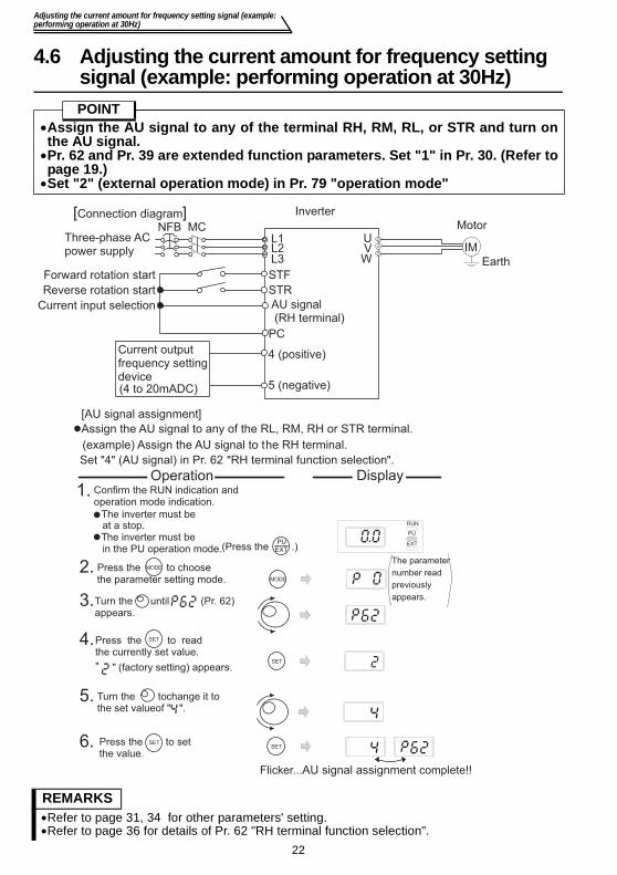
4.6 Adjusting the current amount for frequency setting signal (example: performing operation at 30Hz)POINT
•Assign the AU signal to any of the terminal RH, RM, RL, or STR and turn onthe AU signal.
•Pr. 62 and Pr. 39 are extended function parameters. Set "1" in Pr. 30. (Refer topage 19.)
•Set "2" (external operation mode) in Pr. 79 "operation mode"
REMARKS•Refer to page 31, 34 for other parameters' setting.•Refer to page 36 for details of Pr. 62 "RH terminal function selection".
Three-phase ACpower supply
NFB MC
STFForward rotation start
AU signal (RH terminal)
Motor
IMUVW
Inverter
Current output frequency settingdevice(4 to 20mADC)
Current input selection
Reverse rotation start STR
[Connection diagram]
Earth
PC
L1L2L3
4 (positive)
5 (negative)
Assign the AU signal to any of the RL, RM, RH or STR terminal.
(example) Assign the AU signal to the RH terminal.
[AU signal assignment]
Set "4" (AU signal) in Pr. 62 "RH terminal function selection".
Confirm the RUN indication and operation mode indication.
The inverter must be at a stop.
The inverter must be in the PU operation mode.
MODE
Press the to choose the parameter setting mode.
SET
SET
Turn the until (Pr. 62) appears.
Turn the to change it to the set value of " ".
Press the to set the value.
SET
RUN
PU
EXT
Flicker...AU signal assignment complete!!
Display Operation
PU(Press the .)
" (factory setting) appears."
The parameter
number read
previously
appears.
Press the to read the currently set value.
MODE2.
1.
3.
4.
5.
6.
EXT
SET

23
Adjusting the current amount for frequency setting signal (example:performing operation at 30Hz)
4
RU
N A
ND
OPE
RA
TIO
N
REMARKS•Set frequency at 4mA using calibration parameter C6 and adjust the indicator using calibration parameter C7. (Refer to page 42.)
Operation Display
SETPress the to show the currently set value. SET
Turn the to change it to the set value
of "30.0". (30Hz)
Press the to set the value.SET
Flicker···30Hz output at 20mA current input setting complete!
SET
[Adjust to output 30Hz at 20mA current input]
Set "30Hz" in Pr. 39.
Turn the until (Pr. 39) appears.
Apply currents across terminals 4-5 of the inverter with a current output frequency settingpotentiometer to turn on the start command (STF, STR). Operation starts at 30Hz.
9.
8.
7.
10.
11.
(50Hz)
C7
Output frequency
(Hz)
Frequency setting current signal
Factory Setting
(100% )20mA4mA
C5
( Pr.39 )
0Hz( ) C6(20% )
(Across terminals 4-5)
50Hz

24
5. ADJUSTMENT OF THE FREQUENCY SETTING POTENTIOMETER AND INDICATOR
Related parameters
*1. Settings may differ because of calibration parameters.
*2. Pr. 73 "0-5V/0-10V selection" changes the specifications of terminal "2".
Parameter Name Setting Range Factory Setting38 Frequency setting voltage gain frequency 1 to 120Hz 50Hz39 Frequency setting current gain frequency 1 to 120Hz 50HzC2 Frequency setting voltage bias frequency 0 to 60Hz 0Hz C3 Frequency setting voltage bias 0 to 300% 0% *1C4 Frequency setting voltage gain 0 to 300% 96% *1C5 Frequency setting current bias frequency 0 to 60Hz 0HzC6 Frequency setting current bias 0 to 300% 20% *1C7 Frequency setting current gain 0 to 300% 100% *1
POINT•Bias setting for 0 to 5VDC (0 to 10VDC) input Use the calibration
parameter C2, C3 for setting•Gain setting for 0 to 5VDC (0 to 10VDC) input Use Pr. 38, calibration
parameter C4 for setting. •Bias setting for 4 to 20mADC input Use the calibration
parameter C5, C6 for setting.
•Gain setting for 4 to 20mADC input Use Pr. 39, calibration parameter C7 for setting.
For 4 to 20mADC input, set "4" in any of Pr. 60 to Pr. 63 (input terminalfunction selection) and assign AU (current input selection) to any of terminalsRH, RM, RL and STR, and turn on the AU signal.
C2
C3 (100% C4 ) C6 C7
Frequency setting voltage signal
Pr.38( )
0Hz( )
(0% )5V or 10V0V
Frequency setting current signal
Factory setting
(20% ) (100% )
20mA4mA
Pr.39
C5
( )
0Hz( )
terminals 2-5) terminals 4-5)
Factory setting
Ou
tpu
t
fre
qu
en
cy (
Hz)
Ou
tpu
t
fre
qu
en
cy (
Hz)
(Across (Across
Pr.73 *2
50Hz 50Hz
25
Changing the output frequency setting of the frequency settingpotentiometer (bias and gain of frequency setting voltage (current))
5A
DJU
STM
ENT
OF
THE
FREQ
UEN
CY
SETT
ING
PO
TEN
TIO
MET
ER A
ND
IND
ICA
TOR
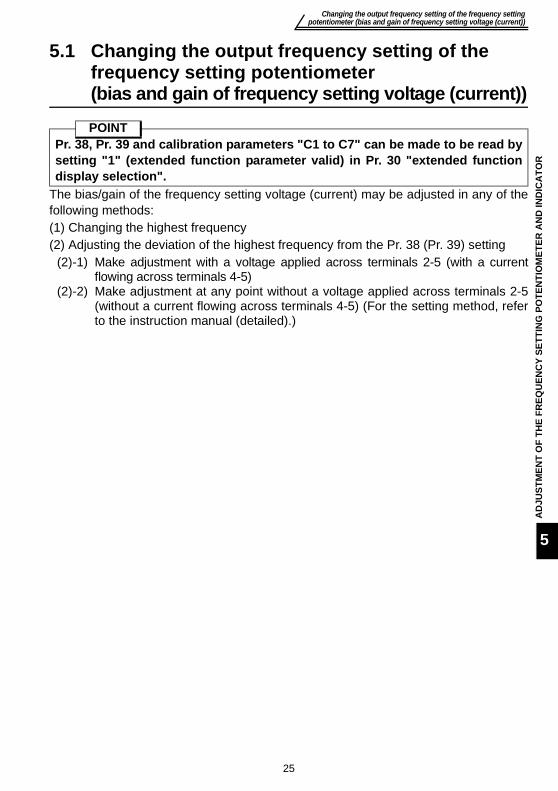
5.1 Changing the output frequency setting of the frequency setting potentiometer (bias and gain of frequency setting voltage (current))
The bias/gain of the frequency setting voltage (current) may be adjusted in any of thefollowing methods:(1) Changing the highest frequency(2) Adjusting the deviation of the highest frequency from the Pr. 38 (Pr. 39) setting
(2)-1) Make adjustment with a voltage applied across terminals 2-5 (with a currentflowing across terminals 4-5)
(2)-2) Make adjustment at any point without a voltage applied across terminals 2-5(without a current flowing across terminals 4-5) (For the setting method, referto the instruction manual (detailed).)
POINTPr. 38, Pr. 39 and calibration parameters "C1 to C7" can be made to be read bysetting "1" (extended function parameter valid) in Pr. 30 "extended functiondisplay selection".

26
Changing the output frequency setting of the frequency setting potentiometer (bias and gain of frequency setting voltage (current))
(1) Changing the highest frequency
Changing example When you want to use the 0 to 5VDC input frequencysetting potentiometer to change the 5V-time frequencyfrom 50Hz (factory setting) to 40Hz.
POINT•Pr. 38 is an extended function parameter. Pr. 30 must be set to "1".(Refer to page 19.)
•Change Pr. 38 "frequency setting voltage gain frequency" to 40Hz.
The monitor/frequency setting indication cannot be changed to just 40Hz ...Why?
The calibration parameter C4 "frequency setting voltage gain" value mustbe set. (Refer to page 27.)
REMARKSTo change the value to more than 50Hz, Pr. 1 "maximum frequency" must be set to more than50Hz.
3. Turn the until Pr. 38 "frequency setting voltage gain frequency" appears.
4.
(Refer to steps 3 to 6 on for the parameter setting method.)
SET
5.
2. MODEMODEPress the to choose
the parameter setting mode.
The parameter number read previously appears.
Pr. 30 must be set to "1"
6. Press the to set the value.
Flicker...Parameter setting complete!!
SET SET
RUN
PU
EXT
1. Confirm the RUN indication and operation mode indication.
PUEXT
The inverter must be in the PU operation mode.
By turning the , you can read another parameter.SETPress the to show the setting again.
SETPress the twice to show the next parameter.
The inverter must be at a stop.
Operation Display
(Press the )
Press the to display the currently set value.(50Hz)
SET
Turn the to change it to "40.0".(40Hz)
page 19

27
Changing the output frequency setting of the frequency settingpotentiometer (bias and gain of frequency setting voltage (current))
5A
DJU
STM
ENT
OF
THE
FREQ
UEN
CY
SETT
ING
PO
TEN
TIO
MET
ER A
ND
IND
ICA
TOR
(2) Adjusting a deviation of the highest frequency from the Pr. 38 (Pr. 39) setting.(2)-1)Making adjustment with a voltage applied directly across terminals 2-5
(with a current flowing across terminals 4-5)
Changing example Changing the calibration parameter C4 "frequency setting voltage gain"POINT
The calibration parameter C4 is an extended function parameter. Pr. 30 mustbe set to "1".
The frequency meter (indicator) connected to across terminals AM-5 does notindicate just 40Hz ... Why?
The calibration parameter C1 "AM terminal calibration" value must be set.(Refer to page 28.)
When write is performed, an error ( ) is displayed. The gain and bias frequency settings are too close.
Turn the until " "
DisplayOperationRUN
PU
EXT
1.
PUEXT(Press the .)
Confirm the RUN indication and operationmode indication.
The inverter must be at a stop.The inverter must be in the PU operation
mode.
3.
MODE
2. MODE
SET4. SETPress the
7.12
34
5 6
7
8
9
10
*
*The value is nearly 100 (%) in the maximum position of the potentiometer.
8. Press the to set the value.SET SET*
Flicker ... Parameter setting complete!!
5. Turn the until thecalibration parameter C4 "frequency setting voltage gain" appears.
6. SETSET
Analog voltage value (%) across terminals 2-5
Press the to show theanalog voltage value (%).
(Adjustment complete)*The value is nearly 100 (%) in the maximum position of the potentiometer.
Apply a 5V voltage.(Turn the external potentiometerconnected to across terminals2-5 to the maximum (any position).)
Press the to choose theparameter setting mode.
By turning the , you can read another parameter.
SETPress the to return to the " " indication (step 4).
SETPress the twice to show the next parameter ( ).
(For details, refer to steps 3 to 6 on .)Pr. 30 must be set to "1".
to show .
The parameter
number read
previously
appears.
" "
appears.
When adjusting Pr. 38
After performing operation in step 7, do not touch the until completion of calibration.
CAUTION
page 19

28
Adjustment (calibration) of the frequency meter (indicator)
5.2 Adjustment (calibration) of the frequency meter (indicator)Changing example Deflecting the meter (analog indicator) to full-scale (5V) at the preset
frequency of 50Hz.(Refer to page 16 for frequency setting.)
POINT•The calibration parameters "C1" can be made to be read by setting "1" (extendedfunction parameter valid) in Pr. 30 "extended function display selection".
•Set the value of the calibration parameter C1 "AM terminal calibration".
REMARKS•Depending on the set value, it may take some time for the needle to move.•If "1" is set in Pr. 30 "extended function display selection", the calibration parameter C1 "AMterminal calibration" can also be set in the external operation mode.
POINTBy setting the Pr. 54 "AM terminal function selection" value, preset Pr. 55"frequency monitoring reference" or Pr. 56 "current monitoring reference" to therunning frequency or current value at which the output signal is 5V.At 5V, the meter generally deflects to full-scale.
By turning the , you can read another parameter.
Press the to return to the " " indication (step 3).
·
·
Press the twice to show the next parameter ( ).·
1. Press the to choose the parameter setting mode.
MODE
4.
5. Press the to enable setting.SET
SET
SET
SET
PU operation mode
2. Turn the to show " " setting.
3. Press the to show " ".
SET
MODE
SET
8. Press the .
Flicker...Parameter setting complete!!
Setting is complete.
6. If the inverter is at a stop, press the to start the inverter.(A motor need not be connected.)
RUN
PU
EXT
RUNRUN
Turn the to adjust the indicator needle to the desired position.
7.
Pr. 30 must be set to "1".
(For details, refer to steps
3 to 6 on .)
The parameter number read previously appears.
Analog indicator
Operation Display
SET
SET
Turn the until the calibration
parameter C1 "AM terminal
calibration" appears.
page 19
29
Basic function parameter list
FUN
CTI
ON
LIS
T
6
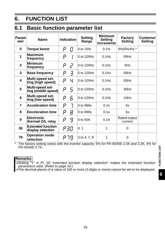
6. FUNCTION LIST6.1 Basic function parameter list
* The factory setting varies with the inverter capacity: 5% for FR-S540E-1.5K and 2.2K, 4% forFR-S540E-3.7K.
Parameter Name Indication Setting
RangeMinimum Setting
IncrementsFactory Setting
Customer Setting
0 Torque boost 0 to 15% 0.1% 6%/5%/4% *
1 Maximum frequency 0 to 120Hz 0.1Hz 50Hz
2 Minimum frequency 0 to 120Hz 0.1Hz 0Hz
3 Base frequency 0 to 120Hz 0.1Hz 50Hz
4 Multi-speed set-ting (high speed) 0 to 120Hz 0.1Hz 50Hz
5 Multi-speed set-ting (middle speed) 0 to 120Hz 0.1Hz 30Hz
6 Multi-speed set-ting (low speed) 0 to 120Hz 0.1Hz 10Hz
7 Acceleration time 0 to 999s 0.1s 5s
8 Deceleration time 0 to 999s 0.1s 5s
9 Electronic thermal O/L relay 0 to 50A 0.1A Rated output
current
30 Extended function display selection 0, 1 1 0
79 Operation mode selection 0 to 4, 7, 8 1 0
Remarks•Setting "1" in Pr. 30 "extended function display selection" makes the extended functionparameters valid. (Refer to page 19.)•The decimal places of a value of 100 or more (3 digits or more) cannot be set to be displayed.

30
Explanation of the basic function parameters
6.2 Explanation of the basic function parametersFor details, refer to the separately available instruction manual (detailed).
Allows the motor torque in the low speedrange to be adjusted according to the load.Make adjustment when stall prevention isoperated when starting.
When a constant-torque motor is used, setthe following value:
Pr. 0 "torque boost"
Values in parenthesis are factory-set
0.2K 0.4K to 0.75K 1.5K 2.2K 3.7K400V class — 6% 4%
(5%)3%
(5%)3%
(4%)200V class 6% 4%
(6%) —
Setting range
Base frequency
0
100%
Output frequency
Pr.0
Pr.3
Out
put
volta
ge
Clamp the upper and lower limits of theoutput frequency.
Pr. 1 "maximum frequency", Pr. 2 "minimum frequency"
Pr.1
Pr.2Frequency setting
Minimum frequency
Maximum frequency
Out
put f
requ
ency
5V(10V)
(20mA) etc.
Set the base frequency (reference frequency at rated motor torque) within the range 0 to 120Hz according to the motor.
As the acceleration time, set the time taken to reach the acceleration/deceleration reference frequency in Pr. 20 from 0Hz (factory set to 50Hz), and as the deceleration time, set the time taken to reach 0Hz from the Pr. 20 value (factory set to 50Hz).
Pr. 3 "base frequency"
Pr. 7 "acceleration time", Pr. 8 "deceleration time"
Acceleration time Deceleration time
Pr.20
Pr.7 Pr.8
0Hz Out
put f
requ
ency
You can select any speed (RH, RM, RL) by simply switching the external contact signal.
Each speed (frequency) can be set to anyvalue within the range 0 to 120Hz if theinverter is running.
The extended functions enable setting ofup to 15 speeds.
Pr. 4 "multi-speed setting (high speed)"Pr. 5 "multi-speed setting (middle speed)"Pr. 6 "multi-speed setting (low speed)"
RH RM RLhigh-speed
middle speedlow speed
OFF OFFOFF
OFF OFFOFFON
ONON

31
Explanation of the basic function parameters
FUN
CTI
ON
LIS
T
6
The inverter has two different operation modes: operation under control of external signalsand operation from the PU (setting dial, ). You can use either or both operation modes.
Pr. 79 "operation mode selection"
Setting Definition0 PU (setting dial, ) operation or external operation can be selected by the .
1 PU (setting dial, ) operation may be performed. 2 Only external operation may be performed.
3
Running frequency Start signal• Setting made by the setting dial• Multi-speed selection• 4 to 20mA (Made valid when the AU signal turns on)
External terminal (STF/STR)
4Running frequency Start signal
External terminal signals (multi-speed, 0 to 5VDC, etc.)
7PU operation interlock(Switching to the PU operation mode is enabled/disabled by turning the MRS signal ON/OFF)
8 Operation mode external signal switching (disabled during operation)Turn the X16 signal ON/OFF to choose operation mode.
Set this parameter when showing/settingthe extended function parameters.
Pr. 30 "extended function display selection"
Setting Definition
0 Only basic functions are displayed.
1 All parameters are displayed.
You can set a current value for protection of the motor from overheat.
At the setting of 0A, motor protection does not function. (The output transistor protection of the inverter functions.)
When connecting multiple motors to the inverter, provide external thermal relays to individual motors.
For the 0.75K or less, this value is factory-set to 85% of the rated inverter current.
Turn the RT signal on to select the second electronic thermal relay function. (Refer to page 41.)
Pr. 9 "electronic thermal O/L relay"
RUN
RUNPU
EXT
RUN
RUN

32
Extended function parameter list
6.3 Extended function parameter listSetting "1" in Pr. 30 "extended function display selection" makes the extended functionparameters valid. (Refer to the separately available instruction manual (detailed).)
Parameter Name Description Factory SettingIndication
For parameters 0 to 9, refer to the basic function parameters. (page 30)
10 DC injection brake operation frequency
Set the timing of switching to DC injection brake (0 to 120Hz), the time to apply DC injection brake (0 to 10s), and the braking torque at DC injection brake start (0 to 15%). (Set Pr. 12 to 4% when a constant-torque motor is used.)
3Hz
11 DC injection brake operation time 0.5s
12 DC injection brake voltage 6%
13 Starting frequency
Frequency which is output by the inverter first at a start and gives great influence to the starting torque. About 1 to 3Hz for vertical lift applications, or up to 5Hz to the maximum. For other than vertical lift applications, factory setting of about 0.5Hz is recommended.0 to 60Hz
0.5Hz
14 Load pattern selection
Choose the output frequency and output voltage patterns according to the application (load characteristic).0: For constant-torque loads (when
relatively large torque is needed at low to high speeds)
1: For variable-torque loads (for applications where torque is small at low speed, e.g. fans and pumps)
2: For vertical lifts(for elevators at reverse rotation boost of 0%)
3: For vertical lifts(for elevators at forward rotation boost of 0%)
0
15 Jog frequencySpeed command (0 to 120Hz) and acceleration/deceleration slope (0 to 999s) for jog (inching) operationWhen the FR-PU04 is connected, these parameters can be read as the basic parameters.
5Hz
16 Jog acceleration/deceleration time 0.5s
17 RUN key rotation direction selection
The of the operation panel can be used to choose the direction of rotation for operation.0: Forward rotation, 1: Reverse rotation
0
19 Base frequency voltage
Indicates the magnitude of the output voltage at the base frequency (Pr.3)888: 95% of power supply voltage- - -: Same as power supply voltage0 to 800V, 888, - - -
888
RUN

33
Extended function parameter list
FUN
CTI
ON
LIS
T
6
20Acceleration/deceleration base frequency
Indicates the frequency to be referenced for acceleration from or deceleration to 0Hz in the time set in Pr. 7 "acceleration time" or Pr. 8 "deceleration time".1 to 120Hz
50Hz
21 Stall prevention function selection
Stall prevention is a function designed to suspend a frequency increase during acceleration, decrease frequency during constant speed or suspend a frequency decrease during deceleration if the preset current (0 to 200%) is exceeded, in order to prevent an overcurrent alarm.Pr. 21 allows you to select whether to use stall prevention or not according to the acceleration/deceleration status.Since the high response current limit value is 170%, torque will not be developed if Pr. 22 is set to more than 170%.In that case, set "1" in Pr. 21.
0
22 Stall prevention operation level 150%
23Stall prevention operation level compensation factor at double speed
Used to reduce the stall prevention level at or above the base frequency.Setting other than "- - -" specifies the current level at 120Hz which is lower than the Pr. 22 value of the stall prevention level at base frequency.0 to 200%, - - -
- - -
24 Multi-speed setting (speed4)
Setting other than "- - -" specifies speeds 4 to 7.By combining ON and OFF of the contact signals (RH, RM, RL signals), the running speed can be changed step-by-step.
0 to 120Hz, - - -
- - -
25 Multi-speed setting (speed 5) - - -
26 Multi-speed setting (speed 6) - - -
27 Multi-speed setting (speed 7) - - -
28Stall prevention operation reduction starting frequency
You can reduce the stall prevention level in the high frequency range.0 to 120Hz
50Hz
29
Acceleration/deceleration pattern
Determines the frequency changing pattern for acceleration/deceleration.0: Linear acceleration/deceleration1: S-pattern acceleration/deceleration A
(e.g. machine tool spindle applications)2: S-pattern acceleration/deceleration B
(for prevention of load shifting in conveyor and other applications.)
0
For parameter 30, refer to the basic function parameters. (page 31)
Parameter Name Description Factory SettingIndication
RH RM RLON ON
ON
ONONONON ONON
Speed 4Speed 5Speed 6Speed 7
OFFOFF
OFF

34
Extended function parameter list
31 Frequency jump 1A
Set the frequency range you want to evade during constant-speed operation to avoid resonance with a machine.0 to 120Hz, - - -
- - -
32 Frequency jump 1B - - -
33 Frequency jump 2A - - -
34 Frequency jump 2B - - -
35 Frequency jump 3A - - -
36 Frequency jump 3B - - -
37 Speed display
You can convert the frequency monitor/set frequency of the operation panel into the load speed and display it. Setting 0 shows the output frequency, and setting 0.1 to 999 shows the load speed.(Set the speed for 60Hz operation.)0, 0.1 to 999
0
38 Frequency setting voltage gain frequency
You can set as desired the magnitude (slope) of the output frequency to the external frequency setting voltage signal (0 to 5V or 0 to 10V).1 to 120Hz
50Hz
39 Frequency setting current gain frequency
You can set as desired the magnitude (slope) of the output frequency to the external frequency setting current signal (4 to 20mA).1 to 120Hz
50Hz
40 Start-time earth fault detection selection
Set whether an earth fault is to be detected or not at a start.0: Not detected1: Detected
1
41 Up-to-frequency
You can adjust the ON range of the up-to-frequency signal (SU) to be output when the output frequency reaches the running frequency. You can use this function to ensure that the running frequency has been reached or use it as the operation start signal etc. for related equipment.Use Pr. 64 or Pr. 65 to assign the terminal used for SU signal output.0 to 100%
10%
42 Output frequency detection
Set the reference value at which the signal (FU) is output when the output frequency rises to or above a certain value. This function can be used for electromagnetic brake operation, open signal, etc.Use Pr. 64 or Pr. 65 to assign the terminal used for the FU signal.0 to 120Hz
6Hz
Parameter Name Description Factory SettingIndication

35
Extended function parameter list
FUN
CTI
ON
LIS
T
6
43Output frequency detection for reverse operation
Set the reference value at which the signal (FU) is output when the output frequency rises to or above a certain value. This function is valid for reverse operation.0 to 120Hz, - - -
- - -
44 Second acceleration/deceleration time
Second function of the acceleration/deceleration time set in Pr. 7, Pr. 8.0 to 999s
5s
45 Second deceleration time
Second function for the deceleration time set in Pr. 8.0 to 999s, - - -
- - -
46 Second torque boostSecond function for the torque boost set in Pr. 0.0 to 15%, - - -
- - -
47 Second V/F (base frequency)
Second function for the base frequency set in Pr. 30 to 120Hz, - - -
- - -
48 Output current detection level
Set the level at which the output current detection signal (Y12) is output.0 to 200%
150%
49Output current detection signal delay time
When the output current is at or above the output current detection level (Pr. 48) for longer than this period (Pr. 49), the output current detection signal (Y12) is output.0 to 10s
0s
50 Zero current detection level
Set the level at which the zero current detection signal (Y13) is output.0 to 200%
5%
51 Zero current detection period
When the output current is at or below the zero current detection level (Pr. 50) for longer than this period (Pr. 51), the zero current detection signal (Y13) is output.0.05 to 1s
0.5s
52 Operation panel display data selection
You can choose the data displayed on the operation panel.0: Output frequency1: Output current100: Set frequency during stop/output frequency during operation
0
53 Frequency setting operation selection
You can use the setting dial like a potentiometer to perform operation.0: Setting dial frequency setting mode1: Setting dial potentiometer mode
0
54 AM terminal function selection
You can choose the indicator connected to the AM terminal.0: Output frequency monitor1: Output current monitor
0
Parameter Name Description Factory SettingIndication

36
Extended function parameter list
55 Frequency monitoring reference
Set the reference value of frequency monitoring.0 to 120Hz
50Hz
56 Current monitoring reference
Set the reference value of current monitoring.0 to 50A
Rated output current
57 Restart coasting time
At power restoration after an instantaneous power failure, you can restart the inverter without motor being stopped (with the motor coasting).The inverter begins to restart after this period (Pr. 57) has elapsed after power restoration.When you set "- - -", a restart is not made. "0" setting generally does not pose a problem but you can adjust the time (0 to 5s, - - -) according to the magnitude of the load.When the restart coasting time (Pr. 57) has elapsed, the output voltage is risen gradually. Set this cushion time (Pr. 58) (0 to 60s).Operation may be performed generally at the factory setting, but you can adjust the time according to the magnitude of the load.Refer to additional parameter H6 for selection of speed search. (Refer to page 41.)
- - -
58 Restart cushion time 1s
59 Remote setting function selection
You can set the remote setting function which is used when the operation panel is away from the enclosure, for example.0: Without remote setting function1: With remote setting function With frequency setting storage function2: With remote setting function Without frequency setting storage function
0
60 RL terminal function selection
You can select the following input signals.0: RL (multiple low-speed operation
command)1: RM (multiple middle-speed operation
command)2: RH (multiple high-speed operation
command)3: RT (second function selection)4: AU (current input selection)5: STOP (start self-holding selection)6: MRS (output stop)7: OH (external thermal relay input)8: REX (15 multi-speed selection)9: JOG (jog operation selection)10: RES (reset)14: X14 (PID control valid terminal)16: X16 (PU operation/external operation
switching)- - -: STR (reverse rotation start (may be
assigned to only STR terminal))
0
61 RM terminal function selection 1
62 RH terminal function selection 2
63 STR terminal function selection - - -
Parameter Name Description Factory SettingIndication

37
Extended function parameter list
FUN
CTI
ON
LIS
T
6
64 RUN terminal function selection
You can select the following input signals.0: RUN (inverter running)1: SU (up-to-frequency)3: OL (overload warning)4: FU (output frequency detection)11: RY (operation ready)12: Y12 (output current detection)13: Y13 (zero current detection)14: FDN (PID lower limit signal)15: FUP (PID upper limit signal)16: RL (PID forward/reverse rotation
signal)93: Y93 (current average value monitor
signal (can be assigned to the RUN terminal only))
95: Y95 (maintenance timer alarm)98: LF (minor failure output)99: ABC (alarm output)
0
65 A, B, C terminal function selection 99
66 Retry selection
You can choose the retry alarm to be activated when the protective function is activated.0: OC1 to 3, OV1 to 3, THM, THT, GF,
OHT, OLT, PE, OPT1: OC1 to 3, 2: OV1 to 3, 3: OC1 to 3, OV1
to 3
0
67 Number of retries at alarm occurrence
You can set the number of retries to be made when the protective function is activated.0: No retry1 to 10: Without alarm output during retry
operation101 to 110: With alarm output during retry
operation
0
68 Retry waiting time
You can set the waiting time from when the protective function is activated until a retry is made.0.1 to 360s
1s
69 Retry count display erase
You can display the cumulative number of successful restarts made by retries when the protective function is activated.0: Cumulative count erase
0
Parameter Name Description Factory SettingIndication

38
Extended function parameter list
70 Soft-PWM setting
You can select whether to exercise Soft-PWM control and long wiring mode.When Soft-PWM is valid, you can change the metallic motor tone into an unoffending complex tone.Surge voltage is suppressed regardless of wiring length if the long wiring mode is set for the 400V class. 1
71 Applied motor
Set the motor to be used.0, 100:
1, 101:0
72 PWM frequency selection
You can change the PWM carrier frequency. Increasing this value reduces the motor audible noise, but increases noise and leakage current.The setting is in [kHz].0: 0.7kHz, 15: 14.5kHz0 to 15(Remarks) Metallic sound may be generated
from the motor at sudden deceleration but it is not a fault.
1
73 0-5V/0-10V selectionYou can set the input voltage specification of terminal "2".0: For 0 to 5VDC input1: For 0 to 10VDC input
0
74 Input filter time constant
Valid for eliminating noise of the frequency setting circuit.A larger set value increases the time constant.0 to 8
1
75 Reset selection/PU stop selection
You can choose the function of the on the operation panel.
14
Parameter Name Description Factory SettingIndication
Soft-PWM Long Wiring Mode0 without without1 with without
10 without with11 with with
Thermal characteristic for Mitsubishi standard motorThermal characteristic for Mitsubishi constant-torque motor
When "100 or 101" is set, turning on the RT signal set the electronic thermal relay function to the thermal characteristic for the constant-torque motor.
STOPRESET
Reset Input PU Stop Key Input0 Normally enabled Invalid (Valid only in
the PU operation mode or combined operation mode (Pr. 79=4))
1Enabled only when the protective function is activated
14 Normally enabledValid15
Enabled only when the protective function is activated

39
Extended function parameter list
FUN
CTI
ON
LIS
T
6
76 Cooling fan operation selection
You can control the operation of the cooling fan built in the inverter. (Operates in power-on status.)0: The fan normally operates at power on
of the inverter.1: The fan is normally on during inverter
operation. The fan switches on/off according to the temperature during a stop of the inverter whose status is monitored.
1
77 Parameter write disable selection
You can choose whether to enable or disable parameter write.0: Write is enabled only during a stop in the
PU operation mode1: Write disabled (except some
parameters)2: Write during operation enabled (external
mode and during operation)
0
78 Reverse rotation prevention selection
You can prevent trouble during reverse operation due to false input of the start signal.0: Both forward rotation and reverse rotation
enabled1: Reverse rotation disabled2: Forward rotation disabled
0
For parameter 79, refer to the basic function parameters. (page 31)
80 Multi-speed setting (speed 8)
Setting other than "- - -" specifies speeds 8 to 15.By combining ON and OFF of the contact signals (RH, RM, RL, REX signals), the running speed can be changed step-by-step.Use Pr. 63 to assign the REX signal.
0 to 120Hz, - - -
- - -
81 Multi-speed setting (speed 9) - - -
82 Multi-speed setting (speed 10) - - -
83 Multi-speed setting (speed 11) - - -
84 Multi-speed setting (speed 12) - - -
85 Multi-speed setting (speed 13) - - -
86 Multi-speed setting (speed 14) - - -
87 Multi-speed setting (speed 15) - - -
88 PID action selectionUsed to choose the operation of PID control.20: PID reverse action, 21: PID forward action
20
89 PID proportional bandUsed to set the proportional band for PID control.0.1 to 999%, - - -
100%
90 PID integral time Used to set the integral time for PID control.0.1 to 999s, - - - 1s
91 PID upper limitUsed to set the upper limit value for PID control.0 to 100%, - - -
- - -
Parameter Name Description Factory SettingIndication
RH RM RL
ON
ONONON
REX
ON
ONONONON ONON
ONONONONONONONON
ON
Speed 8Speed 9Speed 10Speed 11Speed 12Speed 13Speed 14Speed 15
OFFOFFOFFOFF OFF OFF
OFF
OFFOFF
OFF
OFF
OFF
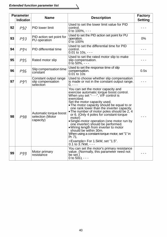
40
Extended function parameter list
92 PID lower limitUsed to set the lower limit value for PID control.0 to 100%, - - -
- - -
93 PID action set point for PU operation
Used to set the PID action set point for PU operation.0 to 100%
0%
94 PID differential timeUsed to set the differential time for PID control.0.01 to 10s, - - -
- - -
95 Rated motor slipUsed to set the rated motor slip to make slip compensation.0 to 50%, - - -
- - -
96 Slip compensation time constant
Used to set the response time of slip compensation.0.01 to 10s
0.5s
97Constant output range slip compensation selection
Used to choose whether slip compensation is made or not in the constant output range.0, - - -
- - -
98 Automatic torque boost selection (Motor capacity)
You can set the motor capacity and exercise automatic torque boost control.When you set "- - -", V/F control is exercised. Set the motor capacity used.•The motor capacity should be equal to or one rank lower than the inverter capacity.
•The number of motor poles should be 2, 4 or 6. (Only 4 poles for constant-torque motor)
•Single-motor operation (one motor run by one inverter) should be performed.
•Wiring length from inverter to motor should be within 30m.
When using a constant-torque motor, set "1" in Pr. 71.
- - -
99 Motor primary resistance
You can set the motor's primary resistance value. (Normally, this parameter need not be set.)0 to 50Ω, - - -
- - -
Parameter Name Description Factory SettingIndication
<Example> For 1.5kW, set "1.5".0.1 to 3.7kW, - - -

41
Extended function parameter list
FUN
CTI
ON
LIS
T
6
Maintenance parameters
Additional parameters
ParameterName Description Factory
SettingIndicationH1
Maintenance timerDisplay the maintenance timer (cumulative energization time) in 1000h increments. Parameter write is not enabled.0 to 999
0(503)
H2Maintenance timer alarm output set time
When the maintenance timer has elapsed the time set in H2, the Y95 signal is output. Assign the Y95 signal with Pr. 64 or Pr. 65.0 to 999, ---
36(36000h)(504)
H3
Current average time
The average value of the output current during constant speed operation and the maintenance timer value are output to the current average value monitor signal (Y93).Y93 signal is output for 20s as 1 cycle in order of start bit for 1s(Hi), output current average value for 0.5 to 9s (Low), maintenance timer value for 2 to 9s (Hi), and end signal (Low).Assign the Y93 signal to the RUN terminal using Pr. 64.Set the time (0.1 to 1s) taken to calculate average value of the output current during constant operation in H3.Set the time (0 to 20s) for not outputting the Y93 signal to invalidate retrieving of output current value in the transient state right after the speed is changed from acceleration/deceleration to constant speed in H4.Set the current value (0.1 to 999A) when outputting the average value of output current as a low pulse shape for 5s in H5.
1s(555)
H4
Data output mask time 0s(556)
H5
Current average value monitor signal output reference current
1A(557)
ParameterName Description
Factory SettingIndication
H6Automatic restart after instantaneous power failure selection
You can select whether to use system to detect the motor speed (speed search system) at the time of restart after instantaneous power failure or not0: with speed search, 1: without speed search, 10: with speed search at starting
1(162)
H7
Second electronic thermal relay function
Protect the second motor from overheat.Set the rated current value of the second motor.Made valid when the RT signal turns on.Refer to Pr. 9 for its function.0 to 50A, ---
- - -(559)

42
Extended function parameter list
Calibration parameter
*Settings may differ because of calibration parameters.
ParameterName Description Factory
SettingIndicationC1
AM terminal calibrationYou can calibrate the indicator connected to across terminals AM-5.—
—(901)
C2Frequency setting voltage bias frequency
You can set as desired the magnitude (slope) of the output frequency to the external frequency setting voltage signal (0 to 5V or 0 to 10V). (Bias frequency)0 to 60Hz
0Hz(902)
C3Frequency setting voltage bias
Used to adjust the analog voltage value of the frequency set in calibration parameter C2. (Bias %)0 to 300%
0%*(902)
C4 Frequency setting voltage gain
Used to adjust the analog voltage value of the frequency set in Pr. 38. (Gain %)0 to 300%
96%*(903)
C5Frequency setting current bias frequency
You can set as desired the magnitude (slope) of the output frequency to the external frequency setting current signal (4 to 20mA).0 to 60Hz
0Hz(904)
C6Frequency setting current bias
Used to adjust the analog current value of the frequency set in calibration parameter C5. (Bias %)0 to 300%
20%*(904)
C7 Frequency setting current gain
Used to adjust the analog current value of the frequency set in Pr. 39 (Gain %)0 to 300%
100%*(905)
C8Parameter for manufacturer setting. Do not set.
(269)
CLr Parameter clear
0: Not executed1: Initialization of parameters other than
calibration values (parameter clear)10: Initialization of parameters including
calibration values (all clear)
0
ECL Alarm history clear 0: Not cleared1: Alarm history clear 0

43
Extended function parameter list
FUN
CTI
ON
LIS
T
6
Communication parametersFor details of the program, etc., refer to the instruction manual (detailed) separatelyavailable.
POINTTo make RS-485 communication between the inverter and personal computer,the operation mode must be set to the "computer link operation mode".Pr. 79 "operation mode selection" ≠ "1, 3, 4"andcommunication parameter n10 "link startup mode selection" = "1"
Parameter Name Description Factory SettingIndication
n1Communication station number*
Set the station number for communication from the RS-485 connector.0 to 31: Specify the station number of the
inverter.0
(331)
n2 Communication speed*
48: 4800bps96: 9600bps192: 19200bps
192(332)
n3Stop bit length*
0: Stop bit length 1 bit/data length 81: Stop bit length 2 bits/data length 810: Stop bit length 1 bit/data length 711: Stop bit length 2 bits/data length 7
1(333)
n4 Parity check presence/absence*
0: Absent1: With odd parity check2: With even parity check
2(334)
n5Number of communication retries
Set the permissible number of retries at occurrence of a data receive error. When you set "- - -", the inverter will not come to an alarm stop if a communication error occurs.0 to 10, - - -
1(335)
n6
Communication check time interval
Set the interval of communication check time. If a no-communication status persists for longer than the permissible time, the inverter will come to an alarm stop.0: No communication0.1 to 999s- - -: Check suspendedTo make communication, set any value other than 0 in the communication parameter n6 "communication check time interval".
- - -(336)
n7
Waiting time setting*
Set the waiting time from when data is transmitted to the inverter until response is made.0 to 150ms- - -: Set in communication data
- - -(337)
n8Operation command source
You can choose whether the operation command is given by the computer or the external terminal.0: Command source is computer1: Command source is external terminal
0(338)

44
Extended function parameter list
* Perform a reset after setting parameter. The set values are reflected after a reset.
Parameters for the PUWhen the parameter unit (FR-PU04) is used, operation from the operation panel is notaccepted.( is valid)
n9Speed command source
You can choose whether the speed command is given by the computer or the external terminal.0: Command source is computer1: Command source is external terminal
0(339)
n10
Link startup mode selection
You can choose the operation mode at power on or at power restoration after instantaneous power failure. Set "1" to select the computer link operation mode.0: Mode set in Pr. 79 is established.1: Started in computer link mode.
0(340)
n11CR/LF selection*
0: Without CR/LF1: With CR, without LF2: With CR/LF
1(341)
n12E2PROM write selection
0: Write to RAM and E2PROM1: Write to RAM only (When a reset is
performed, the parameter value will be the value of E2PROM.)
0(342)
Parameter Name Outline Factory SettingIndication
n13 PU display language selection
0: Japanese, 1: English, 2: German3: French, 4: Spanish, 5: Italian6: Swedish, 7: Finish
1(145)
n14 PU buzzer control 0: Without sound, 1: With sound 1(990)
n15 PU contrast adjustment 58
(991)
n16PU main display screen data selection
0: Selectable between output frequency and output current100: Set frequency (during stop)
Output frequency (during operation)0
(992)
n17Disconnected PU detection/PU setting lock
0: Without PU disconnection error/PU operation valid1: Error at PU disconnection/PU operation valid10: Without PU disconnection error/PU operation invalid
0(993)
REMARKS•The parameter number in parentheses is the one for use with the parameter unit (FR-PU04).•Set "9999" when setting a value "- - -" using the parameter unit (FR-PU04).•Pr. stands for a parameter number.
Parameter Name Description Factory SettingIndication
STOPRESET
63(Dark)
0 (Light)

45
About errors (definitions)
ERR
OR
S A
ND
PR
OTE
CTI
VE F
UN
CTI
ON
S
7
7. ERRORS AND PROTECTIVE FUNCTIONS
7.1 About errors (definitions)When an alarm occurs in the inverter, the protective function is activated to bring theinverter to an alarm stop and the PU display automatically changes to any of thefollowing error (alarm) indications.For details, refer to the separately available instruction manual (detailed).
(1) Major failuresOperation
Panel Indication
Function Name Definition
(OC1)Overcurrent shut-off during acceleration
The inverter output current rose to or above about 200% of the rated inverter current during acceleration.
(OC2)Overcurrent shut-off during constant speed
The inverter output current rose to or above about 200% of the rated inverter current during constant speed operation.
(OC3)Overcurrent shut-off during deceleration
The inverter output current rose to or above about 200% of the rated inverter current during deceleration.
(OV1)Regenerative overvoltage shut-off during acceleration
Excessive regenerative energy or surge voltage occurred during acceleration.
(OV2)Regenerative overvoltage shut-off during constant speed
Excessive regenerative energy or surge voltage occurred during constant speed.
(OV3)
Regenerative overvoltage shut-off during deceleration or stop
Excessive regenerative energy or surge voltage occurred during deceleration or stop.
(THM)Motor overload shut-off(Electronic thermal relay function) (*1)
Overload or reduced cooling capability during low-speed operationProtection against burnout due to motor temperature rise
(THT)Inverter overload shut-off(Electronic thermal relay function) (*1)
Current more than 150% of the rated output current flew and overcurrent shut-off did not occur.Output transistor protection from overheat
(FIN) Fin overheat Temperature rise of the heatsink.
(GF)
Start-time output side earth fault overcurrent protection (*2)
Earth fault occurred on the inverter's output side at a start.
*1. Resetting the inverter initializes the internal thermal integration data of the electronicthermal relay function.
*2. Activated only when "1 (factory setting)" is set in Pr. 40 "start-time earth fault detectionselection".

46
About errors (definitions)
*3. Activated only when any of Pr. 60 to Pr. 63 (input terminal function selection) is set to OH.
(2) Minor failures
(OHT)External thermal relay (*3)
External thermal relay provided for protection from overheat was actuated (contact open).
(OLT)Stall prevention (overload)
Stall prevention was activated to drop the running frequency to 0. (OL appears while stall prevention is activated.)
(OPT) Communication error
• Communication errors occurred consecutively more than the permissible number of retries when the RS-485 connector is used and communication parameter n5 ≠ "- - -".
• RS-485 communication error occurred.• Communication has broken for a period set in
communication parameter n6.
(PE)Parameter storage device alarm Error occurred in the parameter stored.
(PUE) PU disconnected PU was disconnected when communication parameter n17 = "1".
(RET) Retry count over Operation could not be resumed properly within the preset number of retries.
(CPU) CPU error Arithmetic operation of the built-in CPU does not end within the predetermined time.
Operation Panel
IndicationFunction Name Definition
(FN) Fan trouble The cooling fan built in the inverter failed (stopped).
Operation Panel
IndicationFunction Name Definition

47
About errors (definitions)
ERR
OR
S A
ND
PR
OTE
CTI
VE F
UN
CTI
ON
S
7
(3) Warnings
(4) Write errors
Major failure:When the protective function is activated, the inverter output is shut-offand an alarm output is provided.
Minor failure:When the protective function is activated, the output is not shut off.The minor failure signal can be output by making parameter setting.(Set "98" in Pr. 64 or Pr. 65 (output terminal function selection). Referto page 37 .)
Operation Panel
IndicationFunction Name Definition
(OL)Stall prevention (overcurrent) (*4)
Current more than 150% of the rated inverter current flew in the motor and operation is being performed to prevent the inverter from resulting in overcurrent shut-off.
(oL)Stall prevention (overvoltage)
Regenerative energy of the motor became excessive and operation is being performed to stop the frequency from decreasing to prevent overvoltage shut-off.
(PS) PU stop
Pr. 75 "reset selection/PU stop selection" had been set and a stop was made by pressing
the of the operation panel or parameter unit (FR-PU04).
(UV) Undervoltage Power supply voltage of the inverter dropped.
(Err) During reset During inverter reset (RES signal is ON)*4. The stall prevention operation current may be set to any value. It is factory set to 150%.
Operation Panel
IndicationFunction Name Definition
(Er1) Write disable error
• Write was performed with "1" set in Pr. 77• Frequency jump setting range overlapped.• Parameter write was performed though the
operation panel does not have the write precedence.
(Er2)Write-while-running error/mode designation error
• Write was performed during operation.• An attempt was made to change the Pr. 79
setting to the operation mode where the operation command has been input.
• Write was performed in the external operation mode.
(Er3) Calibration error Analog input bias and gain calibration values are too close.
STOPRESET

48
To know the operating status at the occurrence of alarm (only when FR-PU04 is used)
7.2 To know the operating status at the occurrence of alarm (only when FR-PU04 is used)
When any alarm has occurred, the display automatically switches to the indication of the
corresponding protective function (error). By pressing the at this point withoutresetting the inverter, the display shows the output frequency. In this way, it is possible toknow the running frequency at the occurrence of the alarm. It is also possible to knowthe current in the same manner. After resetting, you can confirm the definitions in "AlarmHistory". (For details, refer to the instruction manual of the parameter unit (FR-PU04).)
7.3 Correspondence between digital and actual charactersThere are the following correspondences between the actual alphanumeric charactersand the digital characters displayed on the operation panel:
7.4 Resetting the inverterThe inverter can be reset by performing any of the following operations. Note that theinternal thermal integrated value of the electronic thermal relay function and thenumber of retries are cleared (erased) by resetting the inverter.Recover about 1s after reset is cancelled.
(Err) flickers on the operation panel during reset.Operation 1 ....... Using the operation panel, perform a reset with the .
(Enabled only when the inverter protective function is activated(major failure))
Operation 2 ........ Switch power off once, then switch it on again after the LED turns off.Operation 3 ....... Turn on the reset signal (RES). (Assign this signal to any of Pr. 60 to
Pr. 63.) (Refer to page 36.)
Actual Display Actual Display Actual Display
MON
0
1
2
3
4
5
6
7
8
9
A
B
C
D
E
F
G
H
I
J
L
M
N
O
P
T
U
V
r
-
S
o
STOPRESET

49
Troubleshooting
ERR
OR
S A
ND
PR
OTE
CTI
VE F
UN
CTI
ON
S
7
7.5 TroubleshootingPOINTS
If the cause is still unknown after every check, it is recommended to initialize theparameters (return to factory setting) then re-set the required parameter values andcheck again.
7.5.1 Motor remains stopped
1) Check the main circuit
Check that a proper power supply voltage is applied (operation paneldisplay is provided).Check that the motor is connected properly.Check that the jumper across + - P1 is connected.
2) Check the input signals
Check that the start signal is input.Check that both the forward and reverse rotation start signals are notinput simultaneously.Check that the frequency setting signal is not zero.Check that the AU signal is on when the frequency setting signal is 4 to20mA.Check that the output stop signal (MRS) or reset signal (RES) is not on.(Assign signals MRS and RES using Pr. 60 to Pr. 63 (input terminalfunction selection).)Check that the sink or source jumper connector is fitted securely.
3) Check the parameter settingsCheck that the reverse rotation prevention (Pr. 78) is not selected.Check that the operation mode (Pr. 79) setting is correct.Check that the bias and gain (C2 to C7) settings are correct.Check that the starting frequency (Pr. 13) setting is not greater than therunning frequency.Check that various operational functions (such as three-speed operation),especially the maximum frequency (Pr. 1), are not zero.
4) Check the load
Check that the load is not too heavy.Check that the shaft is not locked.
5) OthersCheck that the operation panel display does not show an error (e.g. OC1).Check that the Pr. 15 "jog frequency" setting is not lower than the Pr. 13"starting frequency" value.

50
Troubleshooting
7.5.2 Motor rotates in opposite directionCheck that the phase sequence of output terminals U, V and W is correct.Check that the start signals (forward rotation, reverse rotation) are connectedproperly.Check the setting of Pr. 17 "RUN key rotation direction selection".
7.5.3 Speed greatly differs from the settingCheck that the frequency setting signal is correct. (Measure the input signallevel.)Check that the following parameter settings are correct (Pr. 1, Pr. 2, Pr. 19, Pr. 38, Pr. 39, Pr. 95, C2 to C7).Check that the input signal lines are not affected by external noise. (Useshielded cables)Check that the load is not too heavy.
7.5.4 Acceleration/deceleration is not smoothCheck that the acceleration and deceleration time settings are not too short.Check that the load is not too heavy.Check that the torque boost setting is not too large to activate the stallprevention function.
7.5.5 Motor current is largeCheck that the load is not too heavy.Check that the torque boost setting is not too large.
7.5.6 Speed does not increaseCheck that the maximum frequency setting is correct.Check that the load is not too heavy. (In agitators, etc., load may becomeheavier in winter.)Check that the torque boost setting is not too large to activate the stall prevention function.
7.5.7 Speed varies during operation
1) Inspection of loadCheck that the load is not varying.
2) Inspection of input signalCheck that the frequency setting signal is not varying.Check that the frequency setting signal is not affected by noise.Check for a malfunction due to an undesirable current when thetransistor output unit is connected.
3) OthersCheck that the wiring length is not too long.Check that GD2 load is not small. (at the motor GD2 or smaller) . . . . . . FR-S540E-1.5K to 3.7KIf so, set the Pr. 72 "PWM frequency selection" to 6kHz or higher.(Check for noise or leakage current problem.)
When slip compensation is selected, the output frequency varies with loadfluctuation between 0 and 2Hz. This is a normal operation and is not a fault.

51
Troubleshooting
ERR
OR
S A
ND
PR
OTE
CTI
VE F
UN
CTI
ON
S
7
................ Check the Pr. 79 setting.When the Pr. 79 "operation mode selection" setting is "0", switching input power on places the inverter in the external operation mode.
Press the to switch to the PU operation mode.For other settings (1 to 8), the operation mode is limited accordingly.(For details of Pr. 79, refer to page 31.)
PUEXT
2. Parameter setting
7.5.8 Operation mode is not changed properly
If the operation mode does not change correctly, check the following:............ Check that the STF or STR signal is off.
When it is on, the operation mode cannot bechanged.
1. External input signal
7.5.9 Operation panel display is not operatingMake sure that terminals PC-SD are not shorted.
Make sure that the connector is fitted securely across terminals + - P1.
Check that the ( ) was pressed.SET WRITE
7.5.10 Parameter write cannot be performedMake sure that operation is not being performed (signal STF or STR is not ON).
Make sure that you are not attempting to set the parameter outside the settingrange.Make sure that you are not attempting to set the parameter in the externaloperation mode.Check Pr. 77 "parameter write disable selection".
7.5.11 Motor produces annoying soundCheck the Pr. 70 "Soft-PWM setting" and Pr. 72 "PWM frequency selection"settings.Make sure that the deceleration time is not too short.

52
Precautions for maintenance and inspection
7.6 Precautions for maintenance and inspectionThe inverter is a static unit mainly consisting of semiconductor devices. Dailyinspection must be performed to prevent any fault from occurring due to the adverseeffects of the operating environment, such as temperature, humidity, dust, dirt andvibration, changes in the parts with time, service life, and other factors.
7.6.1 Precautions for maintenance and inspectionFor some short time after the power is switched off, a high voltage remains in thesmoothing capacitor. When accessing the inverter for inspection, wait for at least 10minutes after the power supply has been switched off, and then make sure that thevoltage across the main circuit terminals + - - of the inverter is not more than 30VDCusing a tester, etc.
7.6.2 Inspection item(1) Daily inspection
•Basically, check for the following faults during operation.1)Motor operation fault2)Improper installation environment3)Cooling system fault4)Abnormal vibration, abnormal noise5)Abnormal overheat, discoloration
• During operation, check the inverter input voltages using a tester.(2) CleaningAlways run the inverter in a clean status.When cleaning the inverter, gently wipe dirty areas with a soft cloth immersed inneutral detergent or ethanol.
7.6.3 Periodic inspectionCheck the areas inaccessible during operation and requiring periodic inspection.Consult us for periodic inspection.1)Cooling system fault. ...........................Clean the air filter, etc.2)Tightening check and retightening........ The screws and bolts may become loose
due to vibration, temperature changes, etc.Check and tighten them.Tighten them according to the specifiedtightening torque.
3)Check the conductors and insulating materials for corrosion and damage.4)Measure insulation resistance.5)Check and replace the cooling fan, smoothing capacitor and relay.
CAUTIONDo not use solvent, such as acetone, benzene, toluene and alcohol, as they willcause the inverter surface paint to peel off.

53
Precautions for maintenance and inspection
ERR
OR
S A
ND
PR
OTE
CTI
VE F
UN
CTI
ON
S
7
7.6.4 Insulation resistance test using megger
1)Before performing the insulation resistance test on the external circuit, disconnectthe cables from all terminals of the inverter so that the test voltage is not applied tothe inverter.
2)For the continuity test of the control circuit, use a tester (high resistance range) anddo not use the megger or buzzer.
3)For the inverter, conduct the insulation resistance test on the main circuit only asshown below and do not perform the test on the control circuit. (use the 500VDCmegger)
7.6.5 Pressure test
Do not conduct a pressure test. Deterioration may occur.
7.6.6 Daily and periodic inspection
Area
of
insp
ectio
n
Inspection Item Inspection Item
Interval
Method Criterion InstrumentC
usto
mer
's
chec
k
Dai
ly
Periodic*
1 ye
ar2
year
Gen
eral
Surrounding environment
Check ambient temperature, humidity, dust, dirt, etc.
Measure 5cm away from the inverter.
Ambient temperature: -10°C to +50°C, non-freezing.Ambient humidity: 90% or less, non-condensing.
Thermometer,hygrometer,recorder
Overall unit Check for unusual vibration and noise.
Visual and auditory checks.
No fault
Power supply voltage
Check that the main circuit voltages are normal.
Measure voltages across inverter terminal block L1, L2, L3 phases.
Within permissible AC (DC) voltage fluctuation(Refer to page 63.)
Tester,digital multimeter
UVW
Inverter
500VDC
megger
Power
supplyIM
MotorL1L2L3
Earth terminal

54
Precautions for maintenance and inspection
Gen
eral
General
(1) Check with megger (across main circuit terminals and earth terminal).
(1) Disconnect all cables from the inverter and measure across terminals L1, L2, L3, U, V, W and earth terminal with megger.,
(2) Retighten(3) Visual
check
(1)5MΩ or more(2), (3) No fault
500VDC class megger
(2) Check for loose screws and bolts
(3) Check for overheat traces on the parts
(4) Cleaning
Mai
n ci
rcui
t
Conductors,cable
(1) Check conductors for distortion.
(1), (2) Visual check
(1), (2) No fault
(2) Check cable sheaths for breakage
Terminal block
Check for damage.
Visual check No fault
Invertermodule,Convertermodule
Check resistance across terminals.
Disconnect all cables from the inverter and measure across terminals L1, L2, L3↔+, - and U, V, W↔+, - with a meter range of 100Ω.
Refer to page 56. Analog tester
Smoothingcapacitor
(1) Check for liquid leakage.
(1), (2) Visual check
(3) Measure with capacity meter
(1), (2) No fault.(3) 85% or more
of the rated capacity
Capacity meter
(2) Check for safety valve projection and bulge.
(3) Measure electrostatic capacity.
Relay
(1) Check for chatter during operation.
(1) Auditory check
(2) Visual check
(1) No fault(2) No fault
(2) Check for rough surface on contacts.
Area
of
insp
ectio
n
Inspection Item Inspection Item
Interval
Method Criterion Instrument
Cus
tom
er's
ch
eck
Dai
ly
Periodic*
1 ye
ar2
year
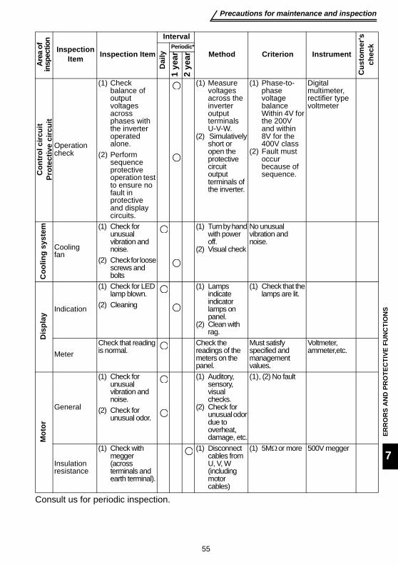
55
Precautions for maintenance and inspection
ERR
OR
S A
ND
PR
OTE
CTI
VE F
UN
CTI
ON
S
7
Consult us for periodic inspection.
Con
trol
circ
uit
Prot
ectiv
e ci
rcui
t
Operationcheck
(1) Check balance of output voltages across phases with the inverter operated alone.
(1) Measure voltages across the inverter output terminals U-V-W.
(2) Simulatively short or open the protective circuit output terminals of the inverter.
(1) Phase-to-phase voltage balance Within 4V for the 200V and within 8V for the 400V class
(2) Fault must occur because of sequence.
Digital multimeter,rectifier type voltmeter
(2) Perform sequence protective operation test to ensure no fault in protective and display circuits.
Coo
ling
syst
em
Coolingfan
(1) Check for unusual vibration and noise.
(1) Turn by hand with power off.
(2) Visual check
No unusual vibration and noise.
(2) Check for loose screws and bolts
Dis
play
Indication
(1) Check for LED lamp blown.
(1) Lamps indicate indicator lamps on panel.
(2) Clean with rag.
(1) Check that the lamps are lit.
(2) Cleaning
MeterCheck that reading is normal.
Check the readings of the meters on the panel.
Must satisfy specified and management values.
Voltmeter, ammeter,etc.
Mot
or
General
(1) Check for unusual vibration and noise.
(1) Auditory, sensory, visual checks.
(2) Check for unusual odor due to overheat, damage, etc.
(1), (2) No fault
(2) Check for unusual odor.
Insulation resistance
(1) Check with megger (across terminals and earth terminal).
(1) Disconnect cables from U, V, W (including motor cables)
(1) 5MΩ or more 500V megger
Area
of
insp
ectio
nInspection
Item Inspection Item
Interval
Method Criterion Instrument
Cus
tom
er's
ch
eck
Dai
ly
Periodic*
1 ye
ar2
year

56
Precautions for maintenance and inspection
Checking the inverter and converter module<Preparation>(1) Disconnect the external power supply cables (L1, L2, L3) and motor cables (U, V, W).(2) Prepare a tester. (Use 100Ω range). <Checking method>Change the polarity of the tester alternately at the inverter terminals L1, L2, L3, U, V,W, P and N, and check for continuity.
Module device numbers and terminals to be checked
(Assumes the use of an analog meter.)
CAUTION•Before measurement, check that the smoothing capacitor is discharged.•At the time of discontinuity, the measured value is almost ∞. When there is aninstantaneous continuity, due to the smoothing capacitor, the tester may notindicate ∞. At the time of continuity, the measured value is several to severalten's-of ohms depending on the module type, circuit tester type, etc. If allmeasured values are almost the same, the modules are without fault.
Tester Polarity Process value
Tester Polarity Process value
Conv
erte
r
Mod
ule
D1 L1 + Discontinuity D4 L1 − Continuity+ L1 Continuity − L1 Discontinuity
D2 L2 + Discontinuity D5 L2 − Continuity+ L2 Continuity − L2 Discontinuity
D3 L3 + Discontinuity D6 L3 − Continuity+ L3 Continuity − L3 Discontinuity
Inve
rter
Mod
ule
TR1 U + Discontinuity TR4 U − Continuity+ U Continuity − U Discontinuity
TR3 V + Discontinuity TR6 V − Continuity+ V Continuity − V Discontinuity
TR5 W + Discontinuity TR2 W − Continuity+ W Continuity − W Discontinuity
REMARKSThe FR-S520SE-0.2K to 1.5K-EC do not have L3, D3 and D6.
Converter module Inverter module
D1 D2 D3
D4 D5 D6
TR1 TR3 TR5
TR4 TR6 TR2
U
V
W
C
−
L1
L2
L3
+
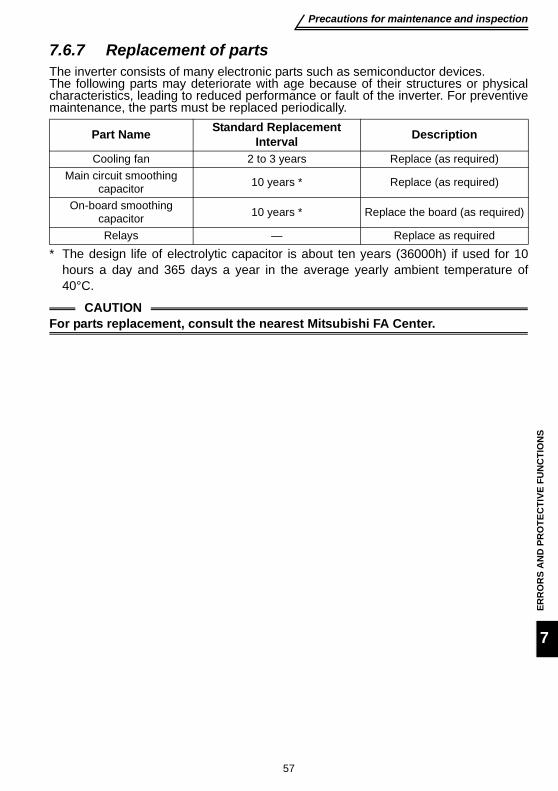
57
Precautions for maintenance and inspection
ERR
OR
S A
ND
PR
OTE
CTI
VE F
UN
CTI
ON
S
7
7.6.7 Replacement of partsThe inverter consists of many electronic parts such as semiconductor devices.The following parts may deteriorate with age because of their structures or physicalcharacteristics, leading to reduced performance or fault of the inverter. For preventivemaintenance, the parts must be replaced periodically.
* The design life of electrolytic capacitor is about ten years (36000h) if used for 10hours a day and 365 days a year in the average yearly ambient temperature of40°C.
Part Name Standard Replacement Interval Description
Cooling fan 2 to 3 years Replace (as required)Main circuit smoothing
capacitor 10 years * Replace (as required)
On-board smoothing capacitor 10 years * Replace the board (as required)
Relays — Replace as required
CAUTIONFor parts replacement, consult the nearest Mitsubishi FA Center.
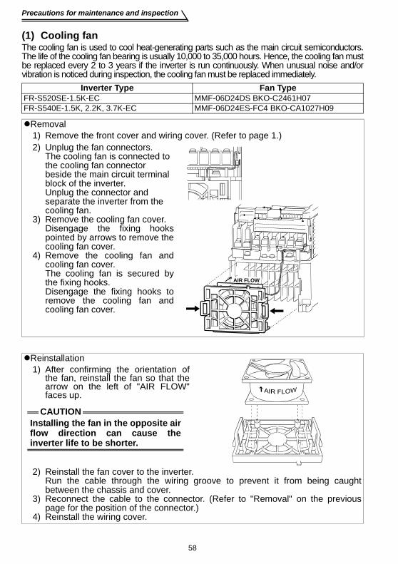
58
Precautions for maintenance and inspection
(1) Cooling fanThe cooling fan is used to cool heat-generating parts such as the main circuit semiconductors.The life of the cooling fan bearing is usually 10,000 to 35,000 hours. Hence, the cooling fan mustbe replaced every 2 to 3 years if the inverter is run continuously. When unusual noise and/orvibration is noticed during inspection, the cooling fan must be replaced immediately.
Inverter Type Fan TypeFR-S520SE-1.5K-EC MMF-06D24DS BKO-C2461H07FR-S540E-1.5K, 2.2K, 3.7K-EC MMF-06D24ES-FC4 BKO-CA1027H09
Removal1) Remove the front cover and wiring cover. (Refer to page 1.)2) Unplug the fan connectors.
The cooling fan is connected to the cooling fan connector beside the main circuit terminal block of the inverter.Unplug the connector and separate the inverter from the cooling fan.
3) Remove the cooling fan cover.Disengage the fixing hookspointed by arrows to remove thecooling fan cover.
4) Remove the cooling fan andcooling fan cover.The cooling fan is secured bythe fixing hooks.Disengage the fixing hooks toremove the cooling fan andcooling fan cover.
Reinstallation1) After confirming the orientation of
the fan, reinstall the fan so that thearrow on the left of "AIR FLOW"faces up.
2) Reinstall the fan cover to the inverter.Run the cable through the wiring groove to prevent it from being caughtbetween the chassis and cover.
3) Reconnect the cable to the connector. (Refer to "Removal" on the previouspage for the position of the connector.)
4) Reinstall the wiring cover.
AIR FLOW
CAUTIONInstalling the fan in the opposite airflow direction can cause theinverter life to be shorter.

59
Precautions for maintenance and inspection
ERR
OR
S A
ND
PR
OTE
CTI
VE F
UN
CTI
ON
S
7
(2) Smoothing capacitorsA large-capacity aluminum electrolytic capacitor is used for smoothing in the maincircuit DC section, and an aluminum electrolytic capacitor is used for stabilizing thecontrol power in the control circuit. Their characteristics are deteriorated by theadverse effects of ripple currents, etc. The replacement intervals greatly vary with theambient temperature and operating conditions. When the inverter is operated in air-conditioned, normal environment conditions, replace the capacitors about every 10years.When a certain period of time has elapsed, the capacitors will deteriorate more rapidly.Check the capacitors at least every year (less than six months if the life will be expiredsoon).The appearance criteria for inspection are as follows:1) Case: Check the side and bottom faces for expansion2) Sealing plate: Check for remarkable warp and extreme crack.3) Check for external crack, discoloration, fluid leakage, etc. Judge that the capacitor
has reached its life when the measured capacitance of the capacitor reduced below85% of the rating.
(3) RelaysTo prevent a contact fault, etc., relays must be replaced according to the cumulativenumber of switching times (switching life).

60
Precautions for maintenance and inspection
7.6.8 Measurement of main circuit voltages, currents and powers• Measurement of voltages and currents
Since the voltages and currents on the inverter power supply and output sidesinclude harmonics, measurement data depends on the instruments used andcircuits measured.When instruments for commercial frequency are used for measurement, measurethe following circuits with the instruments given on the next page.
Examples of Measuring Points and InstrumentsCAUTION
Use an FFT to measure the output voltages accurately.A tester or general measuring instrument cannot measure accurately.
:Moving-iron type
:Electrodynamometer
type
:Moving-coil type
:Rectifier type
+ -
Ar
As
At
Vr
Vs
Vt
W11
W12
W13
Au
Av
Aw
Vu
Vv
Vw
W21
W22
V
U
V
W
Instrument types
Inverter
Three-phase
power supplyTo motor
Inputvoltage
Inputcurrent
Outputvoltage
Outputcurrent
Single-phase 200Vpower input
Three-phase 400Vpower input
+ -
L1
L2
L3
The FR-S520SE-0.2K to 1.5K do not have As, At, Vt, Vs, W12 and W13.
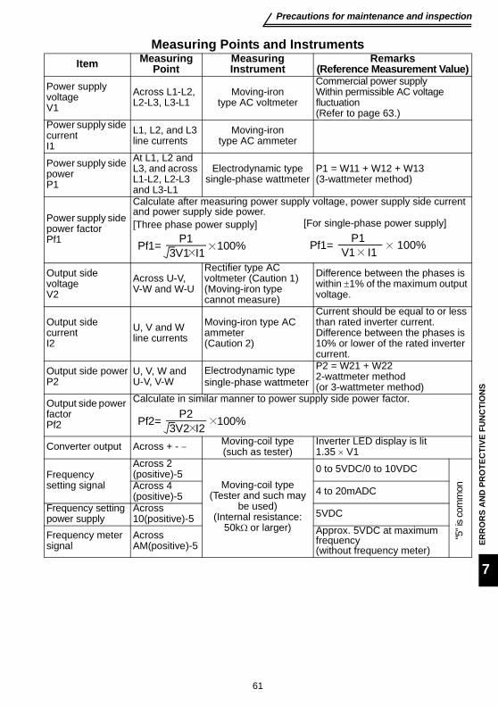
61
Precautions for maintenance and inspection
ERR
OR
S A
ND
PR
OTE
CTI
VE F
UN
CTI
ON
S
7
Measuring Points and InstrumentsItem Measuring
PointMeasuring Instrument
Remarks (Reference Measurement Value)
Power supply voltageV1
Across L1-L2, L2-L3, L3-L1
Moving-iron type AC voltmeter
Commercial power supplyWithin permissible AC voltage fluctuation(Refer to page 63.)
Power supply side currentI1
L1, L2, and L3 line currents
Moving-iron type AC ammeter
Power supply side power P1
At L1, L2 and L3, and across L1-L2, L2-L3 and L3-L1
Electrodynamic type single-phase wattmeter
P1 = W11 + W12 + W13(3-wattmeter method)
Power supply side power factorPf1
Calculate after measuring power supply voltage, power supply side current and power supply side power.[Three phase power supply] [For single-phase power supply]
Output side voltageV2
Across U-V, V-W and W-U
Rectifier type AC voltmeter (Caution 1)(Moving-iron type cannot measure)
Difference between the phases is within ±1% of the maximum output voltage.
Output side currentI2
U, V and W line currents
Moving-iron type AC ammeter(Caution 2)
Current should be equal to or less than rated inverter current.Difference between the phases is 10% or lower of the rated inverter current.
Output side powerP2
U, V, W andU-V, V-W
Electrodynamic type single-phase wattmeter
P2 = W21 + W222-wattmeter method (or 3-wattmeter method)
Output side power factorPf2
Calculate in similar manner to power supply side power factor.
Converter output Across + - − Moving-coil type(such as tester)
Inverter LED display is lit1.35 × V1
Frequency setting signal
Across 2(positive)-5
Moving-coil type(Tester and such may
be used)(Internal resistance:
50kΩ or larger)
0 to 5VDC/0 to 10VDC"5
" is
com
monAcross 4
(positive)-5 4 to 20mADC
Frequency setting power supply
Across 10(positive)-5 5VDC
Frequency meter signal
Across AM(positive)-5
Approx. 5VDC at maximum frequency(without frequency meter)
Pf1= P13V1 I1 100% Pf1= P1
V1 I1 100%
Pf2= P23V2 I2 100%

62
Precautions for maintenance and inspection
Start signalSelect signal
Across STF, STR, RH, RM, RL-PC(positive)
Moving-coil type(Tester and such may
be used)(Internal resistance:
50kΩ or larger)
When open20 to 30VDCON voltage: 1V or less
"PC
" is
com
mon
Alarm signal Across A-CAcross B-C
Moving-coil type(such as tester)
Continuity check<Normal> <Abnormal>
Across A-C: Discontinuity ContinuityAcross B-C: Continuity Discontinuity
CAUTION1. Use an FFT to measure the output voltage accurately. An FA tester or general
measuring instrument cannot measure accurately.2. When the carrier frequency exceeds 5kHz, do not use this instrument since
using it may increase eddy-current losses produced in metal parts inside theinstrument, leading to burnout.In this case, use the approximately effective value type instrument.
Item Measuring Point
Measuring Instrument
Remarks (Reference Measurement Value)
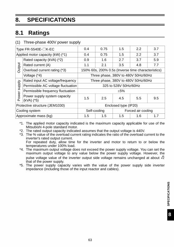
63
Ratings
SPEC
IFIC
ATI
ON
S
8
8. SPECIFICATIONS
8.1 Ratings(1) Three-phase 400V power supply
*1. The applied motor capacity indicated is the maximum capacity applicable for use of theMitsubishi 4-pole standard motor.
*2. The rated output capacity indicated assumes that the output voltage is 440V.*3. The % value of the overload current rating indicates the ratio of the overload current to the
inverter's rated output current. For repeated duty, allow time for the inverter and motor to return to or below thetemperatures under 100% load.
*4. The maximum output voltage does not exceed the power supply voltage. You can set themaximum output voltage to any value below the power supply voltage. However, thepulse voltage value of the inverter output side voltage remains unchanged at about that of the power supply.
*5. The power supply capacity varies with the value of the power supply side inverterimpedance (including those of the input reactor and cables).
Type FR-S540E- K-EC 0.4 0.75 1.5 2.2 3.7Applied motor capacity (kW) (*1) 0.4 0.75 1.5 2.2 3.7
Out
put
Rated capacity (kVA) (*2) 0.9 1.6 2.7 3.7 5.9Rated current (A) 1.1 2.1 3.5 4.8 7.7Overload current rating (*3) 150% 60s, 200% 0.5s (Inverse time characteristics)Voltage (*4) Three phase, 380V to 480V 50Hz/60Hz
Pow
er s
uppl
y Rated input AC voltage/frequency Three phase, 380V to 480V 50Hz/60HzPermissible AC voltage fluctuation 325 to 528V 50Hz/60HzPermissible frequency fluctuation ±5%Power supply system capacity (kVA) (*5) 1.5 2.5 4.5 5.5 9.5
Protective structure (JEM1030) Enclosed type (IP20)Cooling system Self-cooling Forced air coolingApproximate mass (kg) 1.5 1.5 1.5 1.6 1.7
2

64
Ratings
(2) Single-phase 200V power supply
*1. The applied motor capacity indicated is the maximum capacity applicable when aMitsubishi 4-pole standard motor is used.
*2. The rated output capacity indicated assumes that the output voltage is 230V.*3. The % value of the overload current rating indicates the ratio of the overload current to the
inverter's rated output current. For repeated duty, allow time for the inverter to return to or below the temperatures under100% load.
*4. The maximum output voltage does not exceed the power supply voltage. The maximumoutput voltage may be set as desired below the power supply voltage. However, the PWMpulse voltage value of the inverter output side voltage remains unchanged at about that of the power supply.
*5. The power supply capacity changes with the values of the power supply side inverterimpedances (including those of the input reactor and cables).
Type FR-S520SE- K-EC 0.2 0.4 0.75 1.5Applicable motor capacity (kW) (*1) 0.2 0.4 0.75 1.5
Out
put
Rated capacity (kVA) (*2) 0.5 1.0 1.6 2.8Rated current (A) 1.4 2.5 4.1 7.0Overload current rating (*3) 150% 60s, 200% 0.5s (Inverse time characteristics)Voltage (*4) Three phase, 200V to 240V 50Hz/60Hz
Pow
er s
uppl
y Rated input AC voltage/frequency Single-phase, 200V to 240V 50Hz/60HzPermissible AC voltage fluctuation 170 to 264V 50Hz/60HzPermissible frequency fluctuation ±5%Power supply system capacity (kVA) (*5) 0.9 1.5 2.5 4.4
Protective structure (JEM1030) Enclosed type (IP20)
Cooling system Self-cooling Forced air cooling
Approximate mass (kg) 0.6 0.8 1.0 1.5
2

65
Common specifications
SPEC
IFIC
ATI
ON
S
8
8.2 Common specificationsC
ontro
l spe
cific
atio
ns
Control systemSelectable between Soft-PWM control and high carrier frequency PWM control, V/F control or automatic torque boost control are selectable.
Output frequency range 0.5 to 120Hz (starting frequency variable between 0 and 60Hz)
Frequency setting resolution5VDC input: 1/500 of max. set frequency, 10VDC, 4 to 20mADC input: 1/1000 of max. set frequencyDigital input: 0.1Hz (less than 100Hz), 1Hz (100Hz or higher)
Frequency accuracy
Analog input: Within ±1% of max. output frequency (25°C±10°C)Digital input: Within ±0.5% of set output frequency (when set by the setting dial)
Starting torque 150% (at 5Hz) during automatic torque boost control
Acceleration/decelerationtime setting
0, 0.1 to 999s (acceleration and deceleration can be set individually), linear or S-pattern acceleration/deceleration mode can be selected.
Braking torque (*2)
Regeneration 0.2K ... 150%, 0.4K, 0.75K ... 100%, 1.5K ... 50%, 2.2K, 3.7K ... 20%
DC injection brake
Operation frequency (0 to 120Hz), operation time (0 to 10s), operation voltage (0 to 15%)
Inpu
t sig
nals
Frequency setting signal
Analog input 0 to 5VDC, 0 to 10VDC, 4 to 20mA
Digital input Entered from operation panel
Start signal STF, STRForward and reverse rotation, start signal automatic self-holding input (3-wire input) can be selected.
Use Pr. 60 to Pr. 63 for selection
Alarm reset Used to reset alarm output provided when protective function is activated.
Multi-speed selection
Up to 15 speeds can be selected. (Each speed can be set between 0 and 120Hz, running speed can be changed during operation from the operation panel.)
Second function selectionUsed to select second functions (acceleration time, deceleration time, torque boost, base frequency, electronic thermal relay function).
Output stop Instantaneous shut-off of inverter output (frequency, voltage)
Current input selection Used to select frequency setting signal 4 to 20 mA (terminal 4).
External thermal relay input
Thermal relay contact input for use when the inverter is stopped by the external thermal relay.
Jog signal Jog operation mode selectionPID control valid Selection for exercising PID controlPU operation /external operation switchover
Used to switch between PU operation and external operation from outside the inverter.

66
Common specifications
*1. When undervoltage or instantaneous power failure occurs, no alarm output is provided butthe output is shut off. After power restoration, the inverter may be run as it is. Depending onthe running status (e.g. load magnitude), however, overcurrent, regenerative overvoltage orother protection may be activated at power restoration. (in the external operation mode)
*2. The braking torque indicated is a short-duration average torque (which varies with motorloss) when the motor alone is decelerated from 60Hz in the shortest time and is not acontinuous regenerative torque. When the motor is decelerated from the frequency higherthan the base frequency, the average deceleration torque will reduce.
*3. Compatible with only the product having the built-in cooling fan.*4. Activated only when "1 (factory setting)" is set in Pr. 40 "start-time earth fault detection
selection".*5. Activated only when external thermal relay input (OH) is selected in any of Pr. 60 to Pr. 63
(input terminal function selection).*6. Temperature applicable for a short period such as transportation.
Con
trol s
peci
ficat
ions
Operational functions
Maximum and minimum frequency settings, frequency jump operation, external thermal relay input selection, automatic restart after instantaneous power failure, forward/reverse rotation prevention, slip compensation, operation mode selection, PID control, computer link operation (RS-485).
Out
put s
igna
ls
Operating Status
1 open collector signal can be selected from among inverter running, up-to-frequency, frequency detection, overload warning, zero current detection, output current detection, PID upper limit, PID lower limit, PID forward/reverse rotation, operation ready, current average value monitor signal, maintenance timer alarm, minor failure and alarm. 1 contact output (1 contact, 230V 0.3AAC, 30V 0.3ADC) signal can be selected.
Use Pr. 64 and Pr. 65 for selection
For meter 1 signal can be selected from between output frequency and motor current. Analog output (0 to 5VDC)
Protective/warning function
Overcurrent shut-off (during acceleration, deceleration, constant speed), regenerative overvoltage shut-off (during acceleration, deceleration, constant speed), overload shut-off (electronic thermal relay function), heatsink overheat, fan failure (*3), stall prevention, start-time output side earth fault protection (*4), external thermal relay (*5), disconnected PU, retry count over, communication error, CPU error, undervoltage (*1)
Env
ironm
ent
Ambient temperature -10°C to +50°C (non-freezing)
Ambient humidity 90%RH or less (non-condensing)Storage temperature (*6) -20°C to +65°C
Atmosphere Indoors (without corrosive gas, flammable gas, oil mist, dust and dirt etc.)
Altitude, vibrationMaximum 1000m above sea level for standard operation. After that derate by 3% for every extra 500m up to 2500m (91%). 5.9m/s2 or less (conforms to JIS C 60068-2-6)

67
OUTLINE DRAWINGS
OU
TLIN
E D
RA
WIN
GS
9
9. OUTLINE DRAWINGS
•FR-S520SE-0.2K, 0.4K, 0.75K-EC
•Single-phase 200V power supply
(Unit: mm)
Capacity D D1 D20.2K 80.5 10 520.4K 142.5 42 82
0.75K 162.5 62 82
φ5 hole
- +
D1D2D
Rating plate
686 56 6
5
128
511
85
18.54

68
OUTLINE DRAWINGS
•FR-S540E-0.4K, 0.75K, 1.5K, 2.2K, 3.7K-EC•FR-S520SE-1.5K-EC
•Three-phase 400V power supply
•Single-phase 200V power supply
(Unit: mm)
Capacity W W1 D D1 D2 D30.4K,0.75K 108 96 129.5 59 52 5
1.5K 108 96 135.5 65 52 82.2K 108 96 155.5 65 72 83.7K 108 96 165.5 65 82 8
Capacity W W1 D D1 D2 D31.5K 108 96 155.5 65 72 8
REMARKS•The FR-S540E-0.4K, 0.75K-EC do not have a cooling fan.
DD2 D1
D3
WW1
- +
Cooling fan×1
Rating plate
φ5 hole
18.5
118
5
128
5
6 6

69
OUTLINE DRAWINGS
OU
TLIN
E D
RA
WIN
GS
9
•Parameter unit (FR-PU04)<Outline drawing> <Panel cut dimension drawing>
Choose the mounting screws whose length will not exceed the effective depth of themounting threads.
5-M3 hole
5- 4 hole
Effective depth 4.5
40
23.75
11.75
81.5 1.25
1.5
17
16.5
1.5
72 15 10.5
18.5
80
48
24
13
2021.5
14.5
13
40
(Unit:mm)
125

70
(The products conforming to the Low Voltage Directive carry the CE mark.)
(1) EMC Directive1)Our view of transistorized inverters for the EMC Directive
A transistorized inverter is a component designed for installation in an enclosure andfor use with the other equipment to control the equipment/device. Therefore, weunderstand that the EMC Directive does not apply directly to transistorized inverters.For this reason, we do not place the CE mark on the transistorized inverters. (TheCE mark is placed on inverters in accordance with the Low Voltage Directive.) TheEuropean power drive manufacturers' organization (CEMEP) also holds this point ofview.
2)ComplianceWe understand that the transistorized inverters are not covered directly by the EMCDirective. However, the EMC Directive applies to machines/equipment into whichtransistorized inverters have been incorporated, and these machines andequipment must carry the CE marks. Hence, we prepared the European Standard-compliant noise filters and the technical information "EMC Installation Guidelines"(information number BCN-A21041-202) so that machines and equipmentincorporating transistorized inverters may conform to the EMC Directive moreeasily.
3)Outline of installation methodInstall an inverter using the following methods:* Use the inverter with an European Standard-compliant noise filter.* For wiring between the inverter and motor, use shielded cables or run them in a
metal piping and earth the cables on the inverter and motor sides with the shortestpossible distance.
* Insert a line noise filter and ferrite core into the power and control lines as required.Full information including the European Standard-compliant noise filterspecifications are written in the technical information "EMC Installation Guidelines"(BCN-A21041-202). Please contact your sales representative.
Appendix 1 Instructions for compliance with the European Directive

71
(2) Low Voltage Directive1)Our view of transistorized inverters for the Low Voltage Directive
Transistorized inverters are covered by the Low Voltage Directive (Standard toconform to: EN50178).
2)ComplianceWe have self-confirmed our inverters as products compliant to the Low VoltageDirective and place the CE mark on the inverters.
3)Outline of instructions* For the 400V class inverter, the rated input voltage range is three phase 380V to
415V 50Hz/60Hz.* Do not use an earth leakage circuit breaker as an electric shock protector without
connecting the equipment to the earth. Connect the equipment to the earth securely.* Wire the earth terminal independently. (Do not connect two or more cables to one
terminal.)* Use the cable sizes on page 8 under the following conditions.
·Ambient temperature: 40°C maximum·Wire installation: On wall without ducts or conduitsIf conditions are different from above, select appropriate wire according toEN60204 ANNEX C TABLE 5.
* Use the no-fuse breaker and magnetic contactor which conform to the EN or IECStandard.
* Use the breaker of type B (breaker which can detect both AC and DC). If not,provide double or enhanced insulation between the inverter and other equipment,or put a transformer between the main power supply and inverter.
* Use the inverter under the conditions of overvoltage category II and contaminationlevel 2 or higher specified in IEC664.
* On the input and output of the inverter, use cables of the type and size set forth inEN60204 Appendix C.
* The operating capacity of the relay outputs (terminal symbols A, B, C) should be30VDC, 0.3A.
* Control circuit terminals on page 9 are safely isolated from the main circuit.* Environment
Details are given in the technical information "Low Voltage Directive ConformanceGuide" (BCN-A21041-203). Please contact your sales representative.
During operation In storage During transportation
Ambient Temperature -10°C to +50°C -20°C to +65°C -20°C to +65°CAmbient Humidity 90% RH or less 90% RH or less 90% RH or lessMaximum Altitude 1,000m 1,000m 10,000m

72
(Standard to comply with: UL 508C, CSA C22.2 No.14)
1. InstallationThe S500E is UL-listed as a product for use in an enclosure.Design the enclosure so that the ambient temperature, humidity and ambience ofthe inverter will satisfy the above specifications. (Refer to page 66)Branch circuit protectionFor installation in the United States, branch circuit protection must be provided inaccordance with the National Electrical Code and any applicable local codes.For installation in Canada, branch circuit protection must be provided in accordancewith the Canada Electrical Code and any applicable provincial codes.
2. Wiring of the power supply and motorFor wiring the input (L1, L2, L3) and output (U, V, W) terminals of the inverter, usethe UL-listed copper wires (rated at 75°C) and round crimping terminals. Crimp thecrimping terminals with the crimping tool recommended by the terminal maker.
3. Short circuit ratingsSuitable For Use in A Circuit Capable Of Delivering Not More Than 5kA rmsSymmetrical Amperes.
Appendix 2 Instructions for UL and cUL
73
4. Motor overload protectionThese inverters provide solid state motor overload protection.Set Pr. 9 using the following instructions,(Pr. 9 "electronic thermal O/L relay").
<Setting>•Set the rated current [A] of the motor in Pr. 9.•Setting "0" in Pr. 9 disables electronic thermal relay function (motor protective func-tion). (The protective function of the inverter is activated.)
•When using a Mitsubishi constant-torque motor, first set "1" in Pr. 71 "applied motor".(This provides a 100% continuous torque characteristic in the low-speed range.)Then, set the rated current of the motor in Pr. 9 "electronic thermal O/L relay".
CAUTION•When two or more motors are connected to the inverter, they cannot be protected bythe electronic thermal relay function. Install an external thermal relay to each motor.•When a difference between the inverter and motor capacities is large and the settingbecomes less than half amount of the inverter rated current, the protectivecharacteristics of the electronic thermal relay function will be deteriorated. In this case,use an external thermal relay.•A special motor cannot be protected by the electronic thermal relay function.Use an external thermal relay.
Reference: Motor overload protection characteristics
0 50 100 150 180200
240
180
120
60
Ope
ratio
n tim
e (s
)
50% setting(Note 1, 2)
100% setting(Note 2)
(Note 1) When you set the 50% value (current value) of the rated inverter output current.(Note 2) The % value denotes the percentage of the current value to the rated inverter output current, not to the rated motor current.(Note 3) This characteristic curve will be described even under operation of 6Hz or higher when you set the electronic thermal relay function dedicated to the Mitsubishi constant-torque motor.
30Hz or higher (Note 3)
Inverter output current (%)(% to rated inverter output current)
Electronic thermal relayfunction for transistorprotection
20Hz10Hz
Protection activating range Range on the right of characteristic curveNormal operating rangeRange on the left of characteristic curve
REVISIONS* The manual number is given on the bottom left of the back cover.
For Maximum Safety• Mitsubishi transistorized inverters are not designed or manufactured to be used in
equipment or systems in situations that can affect or endanger human life.• When considering this product for operation in special applications such as
machinery or systems used in passenger transportation, medical, aerospace,atomic power, electric power, or submarine repeating applications, please contactyour nearest Mitsubishi sales representative.
• Although this product was manufactured under conditions of strict quality control,you are strongly advised to install safety devices to prevent serious accidents whenit is used in facilities where breakdowns of the product are likely to cause a seriousaccident.
• Please do not use this product for loads other than three-phase induction motors.
Print Date *Manual Number RevisionSep., 2004 IB(NA)-0600210ENG-A First edition

INDUSTRIAL AUTOMATION
MITSUBISHI ELECTRIC
MITSUBISHI ELECTRICGothaer Strasse 8 Phone: +49 2102 486-0 Fax: +49 2102 486-717 www.mitsubishi-automation.deD-40880 Ratingen Hotline: +49 2102 1805 000-765 [email protected] www.mitsubishi-automation.com
HEADQUARTERS
MITSUBISHI ELECTRIC EUROPEEUROPE B.V.German BranchGothaer Straße 8D-40880 RatingenPhone: +49 (0)2102 486-0Fax: +49 (0)2102 486-1120e mail: [email protected] ELECTRIC FRANCEEUROPE B.V.French Branch25, Boulevard des BouvetsF-92741 Nanterre CedexPhone: +33 1 55 68 55 68Fax: +33 1 55 68 56 85e mail: [email protected] ELECTRIC IRELANDEUROPE B.V.Irish BranchWestgate Business Park, BallymountIRL-Dublin 24Phone: +353 (0) 1 / 419 88 00Fax: +353 (0) 1 / 419 88 90e mail: [email protected] ELECTRIC . ITALYEUROPE B.VItalian BranchVia Paracelso 12I-20041 Agrate Brianza (MI)Phone: +39 039 60 53 1Fax: +39 039 60 53 312e mail: [email protected] ELECTRIC SPAINEUROPE B.V.Spanish BranchCarretera de Rubí 76-80E-08190 Sant Cugat del VallésPhone: +34 9 3 565 3131Fax: +34 9 3 589 2948e mail: [email protected] ELECTRIC UKEUROPE B.V.UK BranchTravellers LaneGB-Hatfield Herts. AL10 8 XBPhone: +44 (0) 1707 / 27 61 00Fax: +44 (0) 1707 / 27 86 95e mail: [email protected] ELECTRIC JAPANCORPORATIONOffice Tower “Z” 14 F8-12,1 chome, Harumi Chuo-KuTokyo 104-6212Phone: +81 3 622 160 60Fax: +81 3 622 160 75MITSUBISHI ELECTRIC USAAUTOMATION500 Corporate Woods ParkwayVernon Hills, IL 60061Phone: +1 847 478 21 00Fax: +1 847 478 22 83
EUROPEAN REPRESENTATIVES
GEVA AUSTRIAWiener Straße 89AT-2500 BadenPhone: +43 (0)2252 / 85 55 20Fax: +43 (0)2252 / 488 60e mail: [email protected] BELARUSOktjabrskaya 16/5, Ap 704BY-220030 MinskPhone: +375 (0)17 / 2104626Fax: +375 (0)17 / 2275830e mail: [email protected] b.v. BELGIUMControl SystemsPontbeeklaan 43BE-1731 Asse-ZellikPhone: +32 (0)2 / 467 17 51Fax: +32 (0)2 / 467 17 45e mail: [email protected] CO. BULGARIA4, A. Ljapchev Blvd.BG-1756 SofiaPhone: +359 (0)2 / 97 44 058Fax: +359 (0)2 / 97 44 061e mail: —INEA CR d.o.o. CROATIALosinjska 4 aHR-10000 ZagrebPhone: +385 (0) 1 / 36 940-01Fax: +385 (0) 1 / 36 940-03e mail: [email protected] CZECH REPUBLICControl Systems s.r.o.Nemocnicni 12CZ-70200 Ostrava 2Phone: +420 59 / 6152 111Fax: +420 59 / 6152 562e mail: [email protected] poulsen DENMARKindustri & automationGeminivej 32DK-2670 GrevePhone: +45 (0)43 / 95 95 95Fax: +45 (0)43 / 95 95 91e mail: [email protected] Elektrotehnika AS ESTONIAPärnu mnt.160iEE-10621 TallinnPhone: +372 (0)6 / 51 72 80Fax: +372 (0)6 / 51 72 88e mail: [email protected] POWEL OY FINLANDBox 236FIN-28101 PoriPhone: +358 (0)2 / 550 800Fax: +358 (0)2 / 550 8841e mail: [email protected] A.B.E.E. GREECE5, Mavrogenous Str.GR-18542 PiraeusPhone: +302 (0)10 / 42 10 050Fax: +302 (0)10 / 42 12 033e mail: [email protected] Automatika Kft. HUNGARY55, Harmat St.HU-1105 BudapestPhone: +36 (0)1 / 2605 602Fax: +36 (0)1 / 2605 602e mail: [email protected] POWEL LATVIALienes iela 28LV-1009 RigaPhone: +371 784 2280Fax: +371 784 2281e mail: [email protected] UTU POWEL LITHUANIASavanoriu Pr. 187LT-2053 VilniusPhone: +370 (0)52323-101Fax: +370 (0)52322-980e mail: [email protected]
EUROPEAN REPRESENTATIVES
Intehsis Srl MOLDOVACuza-Voda 36/1-81MD-2061 ChisinauPhone: +373 (0)2 / 562 263Fax: +373 (0)2 / 562 263e mail: [email protected] b.v. NETHERLANDSControl SystemsDonauweg 2 BNL-1043 AJ AmsterdamPhone: +31 (0)20 / 587 6700Fax: +31 (0)20 / 587 6839e mail: [email protected] Control NETHERLANDSAutomation b.v.Markenweg 5NL-7051 HS VarsseveldPhone: +31 (0)315 / 257 260Fax: +31 (0)315 / 257 269e mail: —Beijer Electronics AS NORWAYTeglverksveien 1NO-3002 DrammenPhone: +47 (0)32 / 24 30 00Fax: +47 (0)32 / 84 85 77e mail: [email protected] Technology Sp. z o.o. POLANDul. Sliczna 36PL-31-444 KrakówPhone: +48 (0)12 / 632 28 85Fax: +48 (0)12 / 632 47 82e mail: [email protected] Trading & Services srl ROMANIAStr. Biharia Nr. 67-77RO-013981 Bucuresti 1Phone: +40 (0) 21 / 201 1146Fax: +40 (0) 21 / 201 1148e mail: [email protected] SR d.o.o. SERBIA AND MONTENEGROKaradjordjeva 12/260SCG-113000 SmederevoPhone: +381 (0)26/ 617 - 163Fax: +381 (0)26/ 617 - 163e mail: [email protected] Autocomp a.s. SLOVAKIAChalupkova 7SK-81109 BratislavaPhone: +421 (02)5292-2254Fax: +421 (02)5292-2248e mail: [email protected] d.o.o. SLOVENIAStegne 11SI-1000 LjubljanaPhone: +386 (0)1 513 8100Fax: +386 (0)1 513 8170e mail: [email protected] Electronics AB SWEDENBox 426S-20124 MalmöPhone: +46 (0)40 / 35 86 00Fax: +46 (0)40 / 35 86 02e mail: [email protected] AG SWITZERLANDPostfach 282CH-8309 NürensdorfPhone: +41 (0)1 / 838 48 11Fax: +41 (0)1 / 838 48 12e mail: [email protected] TURKEYDarülaceze Cad. No. 43A KAT: 2TR-80270 Okmeydani-IstanbulPhone: +90 (0)212 / 320 1640Fax: +90 (0)212 / 320 1649e mail: [email protected] Automation UKRAINE15, M. Raskova St., Fl. 10, Off. 1010UA-02002 KievPhone: +380 (0)44 / 238 83 16Fax: +380 (0)44 / 238 83 17e mail: [email protected]
EURASIAN REPRESENTATIVES
Avtomatika Sever Ltd. RUSSIALva Tolstogo St. 7, Off. 311RU-197376 St PetersburgPhone: +7 812 / 11 83 238Fax: +7 812 / 11 83 239e mail: [email protected] RUSSIAPromyshlennaya St. 42RU-198099 St PetersburgPhone: +7 812 / 325 36 53Fax: +7 812 / 325 36 53e mail: [email protected] RUSSIAPoslannikov Per., 9, Str.1RU-107005 MoscowPhone: +7 095 / 542-4323Fax: +7 095 / 956-7526e mail: [email protected] RUSSIAKrasnij Prospekt 220-1, Office 312RU-630049 NovosibirskPhone: +7 3832 / 10 66 18Fax: +7 3832 / 10 66 26e mail: [email protected] RUSSIARyazanskij Prospekt, 8A, Office 100RU-109428 MoscowPhone: +7 095 / 232 0207Fax: +7 095 / 232 0327e mail: [email protected] RUSSIAPolzunova 7RU-630051 NovosibirskPhone: +7 095 / 416 4321Fax: +7 095 / 416 4321e mail: [email protected] Drive Technique RUSSIAPoslannikov per., 9, str.1RU-107005 MoscowPhone: +7 095 / 786 21 00Fax: +7 095 / 786 21 01e mail: [email protected]
MIDDLE EAST REPRESENTATIVE
SHERF Motion Techn. Ltd ISRAELRehov Hamerkava 19IL-58851 HolonPhone: +972 (0)3 / 559 54 62Fax: +972 (0)3 / 556 01 82e mail: —
AFRICAN REPRESENTATIVE
CBI Ltd SOUTH AFRICAPrivate Bag 2016ZA-1600 IsandoPhone: +27 (0)11 / 928 2000Fax: +27 (0)11 / 392 2354e mail: [email protected]
INV
12.0
4-P
rinte
din
Germ
any