Embed Size (px)
Citation preview
ORGANIC LIGHT EMITTING DIODE
AN OLED is a Organic Light Emitting DiodeIn which emissive electroluminescent layer is a film of organic compound which emits lightIn response to an electric current. This layerOf organic semiconductor suited between to Electrodes. Generally one of the electrode is Transparent. OLEDS are used to create digital displays in devices such as screens. An OLED works without back Light. Inflow ambient light conditions such as a dark room an OLED screens can achieve a higher contrast ratio than an LCD ,whether the LCD uses cold Cathode Fluorescent Lamps or LED back light. OLED technology was firstly developed in1987 at East men kodak company by Tang and Van slyke using small molecule (sm-OLED). IN 1990 Richard friend and Jeremy Burroughes and DonaldBradley discovered electroluminescence capabilities from conjugate polymers so lying down the new generation of flat panel displays
(OLED)
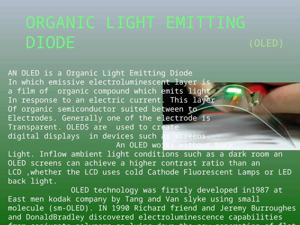
How OLED EMITS LIGHT1. Voltage applied across
Cathode and Anode1. Typically 2V-10V
2. Current flows from cathode to anode
1. Electrons flow to emissive layer
2. Electrons removed from conductive layer leaving holes
3. Holes jump into emissive layer
3. Electron and hole combine and light emitted
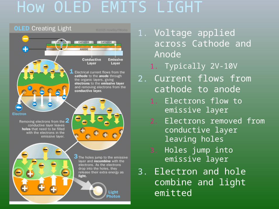
OLED ProcessProcess involves to stages:-
1. Pre encapsulation process2. Continuous operation inside chambers
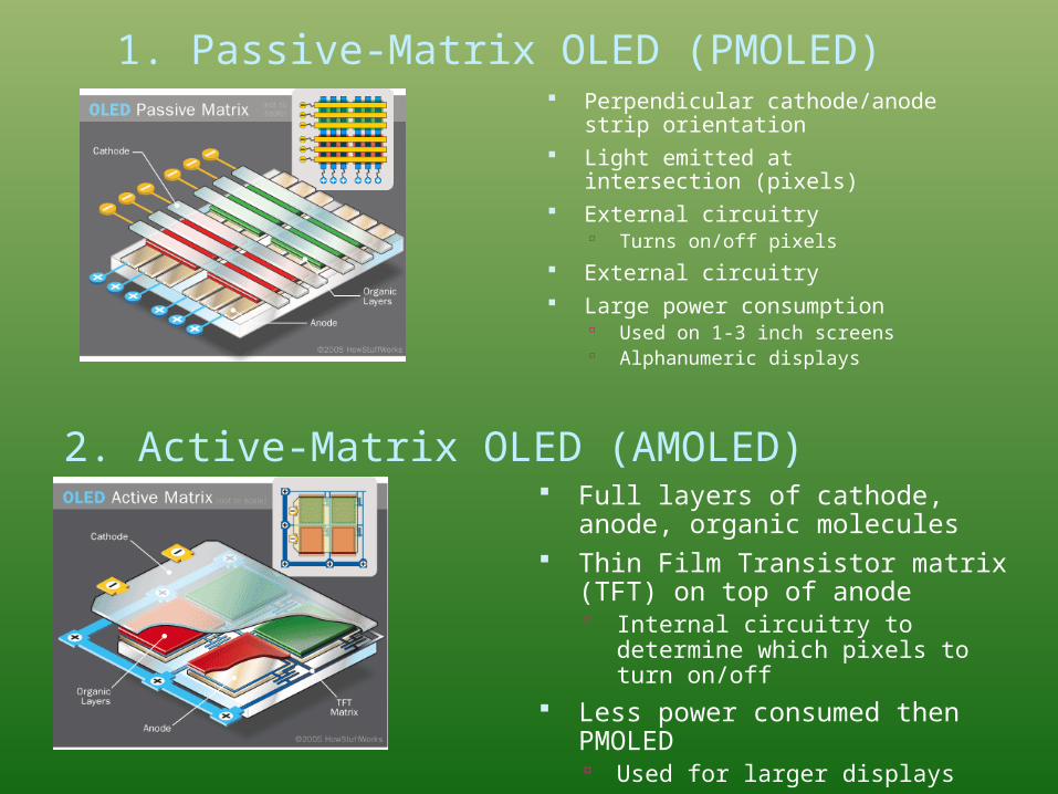
1. Passive-Matrix OLED (PMOLED) Perpendicular cathode/anode
strip orientation Light emitted at intersection
(pixels) External circuitry
Turns on/off pixels External circuitry Large power consumption
Used on 1-3 inch screens Alphanumeric displays
2. Active-Matrix OLED (AMOLED) Full layers of cathode, anode,
organic molecules Thin Film Transistor matrix (TFT)
on top of anode Internal circuitry to determine
which pixels to turn on/off Less power consumed then
PMOLED Used for larger displays
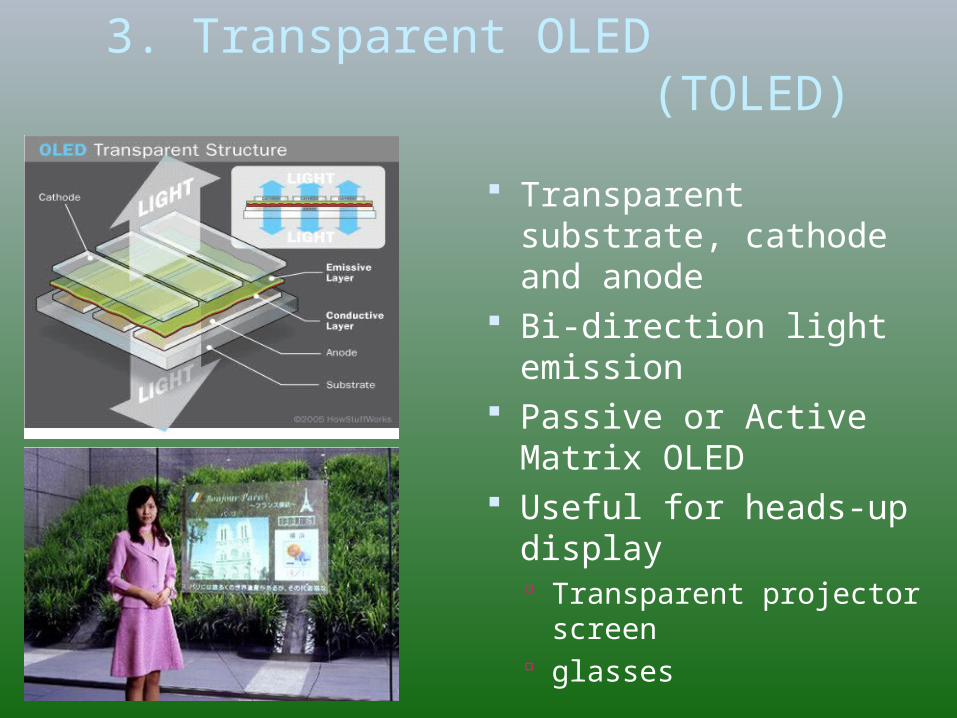
3. Transparent OLED (TOLED)
Transparent substrate, cathode and anode
Bi-direction light emission
Passive or Active Matrix OLED
Useful for heads-up display Transparent projector
screen glasses
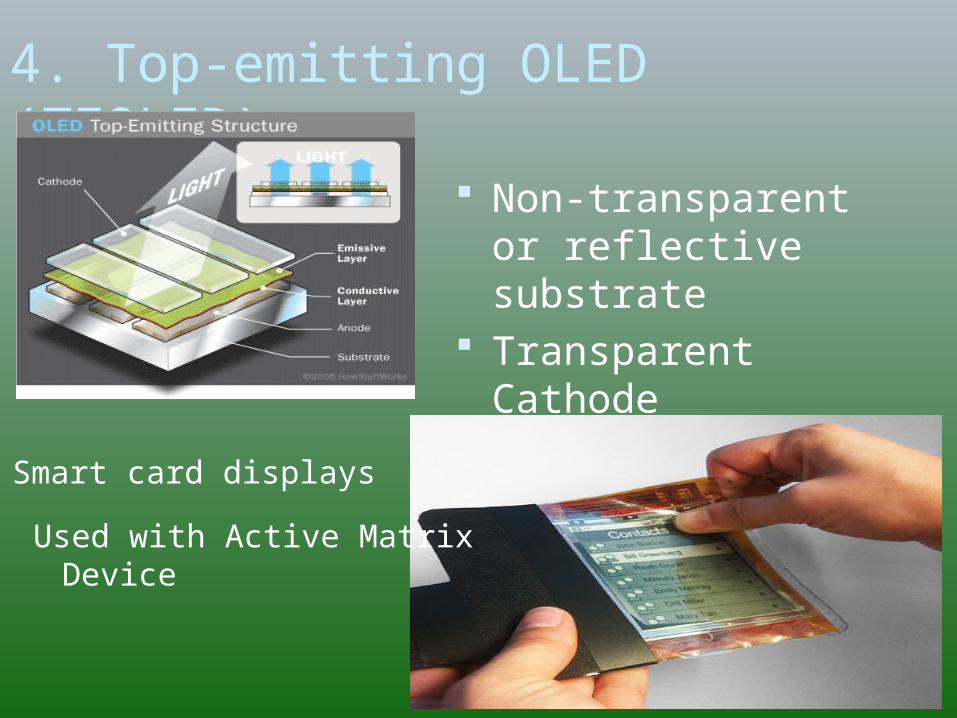
4. Top-emitting OLED (TEOLED)
Non-transparent or reflective substrate
Transparent Cathode
Smart card displays
Used with Active Matrix Device
OLED Advantages over LED and LCD Thinner, lighter and more flexible
Plastic substrates rather then glass High resolution (<5um pixel size) and fast switching (1-
10um) Do not require backlight, light generated Low voltage, low power and emissive source Robust Design (Plastic Substrate) Larger sized displays Brighter- good daylight visibility Larger viewing angles -170o Colour Gamut comparable to CRT, with potential to get better – Striking
visual appeal Thinner – No backlight Less Expensive than LCD due to lesser components
White + Color Filter route takes away some of this advantage Potential for printing in manufacturing. Flexible and Conformal Displays
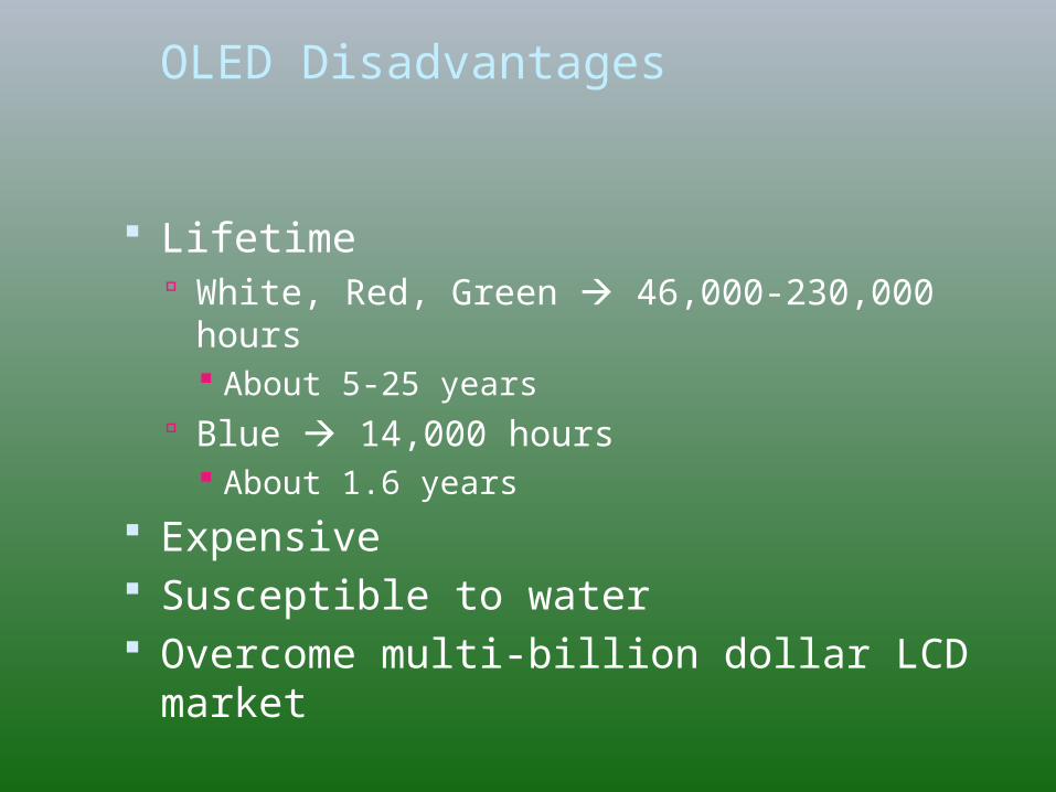
OLED Disadvantages
Lifetime White, Red, Green 46,000-230,000 hours
About 5-25 years Blue 14,000 hours
About 1.6 years Expensive Susceptible to water Overcome multi-billion dollar LCD
market
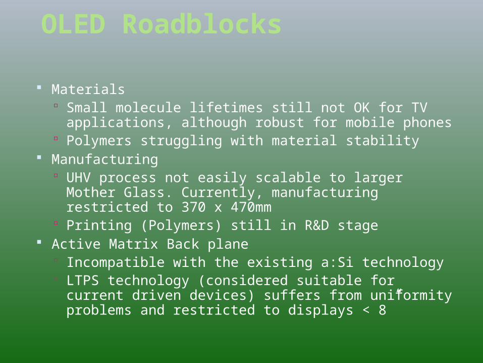
OLED Roadblocks
Materials Small molecule lifetimes still not OK for TV
applications, although robust for mobile phones Polymers struggling with material stability
Manufacturing UHV process not easily scalable to larger Mother
Glass. Currently, manufacturing restricted to 370 x 470mm
Printing (Polymers) still in R&D stage Active Matrix Back plane
Incompatible with the existing a:Si technology LTPS technology (considered suitable for current
driven devices) suffers from uniformity problems and restricted to displays < 8”
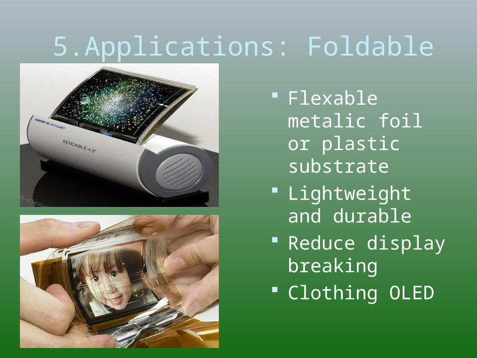
5.Applications: Foldable OLED
Flexable metalic foil or plastic substrate
Lightweight and durable
Reduce display breaking
Clothing OLED
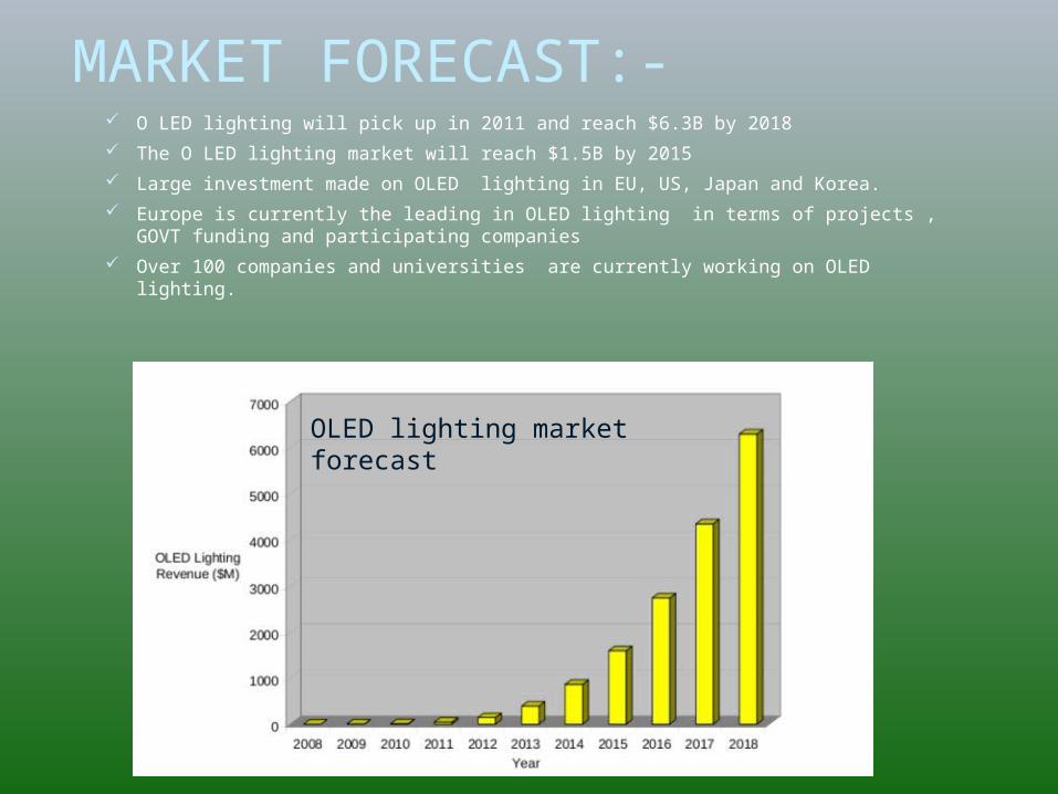
MARKET FORECAST:- O LED lighting will pick up in 2011 and reach $6.3B by 2018 The O LED lighting market will reach $1.5B by 2015 Large investment made on OLED lighting in EU, US, Japan and Korea. Europe is currently the leading in OLED lighting in terms of projects , GOVT
funding and participating companies Over 100 companies and universities are currently working on OLED lighting.
OLED lighting market forecast
Limited use caused by degradation of materials.
OLED will replace current LED and LCD technologies
Expensive Flexibility and thinness will enable
many applications
Conclusions
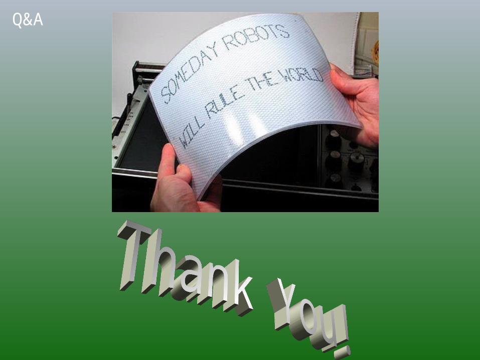
Q&A