Embed Size (px)
Citation preview
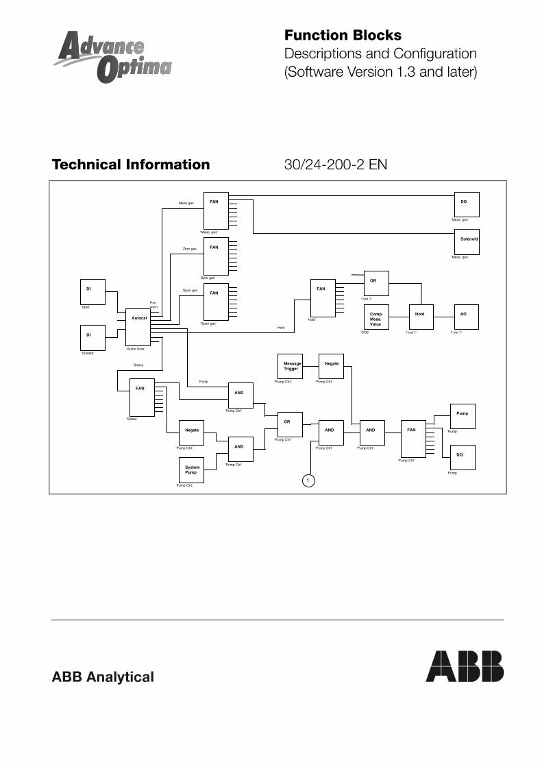
Function BlocksDescriptions and Configuration(Software Version 1.3 and later)
Technical Information 30/24-200-2 EN
DO
‘Meas. gas‘
Solenoid
‘Meas. gas‘
FAN
‘Meas. gas’
FAN
‘Zero gas’
FAN
‘Span gas’
FAN
‘Status’
Autocal
‘Autoc Uras’
DI
‘Start‘
DI
‘Disable‘
FAN
‘Hold’
OR
‘I out 1‘
Hold
‘I out 1‘
AO
‘I out 1‘
Comp.Meas.Value
‘CO2‘
Meas gas
Zero gas
Span gas
Hold
Status
AND
‘Pump Ctrl‘
OR
‘Pump Ctrl‘
Negate
‘Pump Ctrl.‘ AND
‘Pump Ctrl‘SystemPump
‘Pump Ctrl.’
AND
‘Pump Ctrl‘
AND
‘Pump Ctrl‘
FAN
‘Pump Ctrl.’
Pump
‘Pump‘
DO
‘Pump‘
Negate
‘Pump Ctrl‘Pump
MessageTrigger
‘Pump Ctrl.‘
1
Pre-warn.
2 Function Blocks – Descriptions and Configuration 30/24-200-2 EN
Contents
Page
A few preliminary words ............................................................................................ 3
Chapter 1 ConfigurationWhat are function blocks? ......................................................................................... 4Standard Configuration.............................................................................................. 7Example: "Limit Monitor"............................................................................................ 8Example: "Range Control/Feedback" ....................................................................... 9Function Block Linking and Initializing ..................................................................... 11Function Block Linking............................................................................................. 13
Chapter 2 DescriptionsFunction Block Overview ......................................................................................... 18Limit Monitor ............................................................................................................ 19Hold ......................................................................................................................... 20Feedback................................................................................................................. 21Timer ....................................................................................................................... 22Sequencer ............................................................................................................... 24Access Lock ............................................................................................................ 26Digital Input.............................................................................................................. 27Analog Input ............................................................................................................ 28Message Input ......................................................................................................... 29Constant .................................................................................................................. 30Digital Output........................................................................................................... 31Analog Output.......................................................................................................... 32Message Insert ........................................................................................................ 34Negate ..................................................................................................................... 35Add .......................................................................................................................... 36Subtract ................................................................................................................... 37Multiply .................................................................................................................... 38Divide....................................................................................................................... 39Or............................................................................................................................. 40And .......................................................................................................................... 41Linear Converter...................................................................................................... 42Fan .......................................................................................................................... 43Multiplexer ............................................................................................................... 44Demultiplexer........................................................................................................... 45Priority Encoder ....................................................................................................... 46Priority Decoder....................................................................................................... 47Binary → Decimal.................................................................................................... 48Decimal → Binary.................................................................................................... 49Component Measured Value ................................................................................... 50Detector Measured Value ........................................................................................ 51Component Range .................................................................................................. 52Range Control ......................................................................................................... 53Range Feedback ..................................................................................................... 54Active Component Multiplexer................................................................................. 55Calibration Cell ........................................................................................................ 57Solenoids................................................................................................................. 58System Pump .......................................................................................................... 59Pump ....................................................................................................................... 60Autocalibration......................................................................................................... 61Externally Controlled Calibration ............................................................................. 63Cross-Sensitivity Correction .................................................................................... 64Carrier Gas Correction ............................................................................................ 65
30/24-200-2 EN Function Blocks – Descriptions and Configuration 3
A few preliminary words ...
... on the content ofthis TechnicalInformationPublication
This technical information publication contains information on the Advance Optimaanalyzer system function blocks.
Chapter 1 describes what function blocks are and how they are configured.
Chapter 2 contains a detailed description of the use and functionality of eachfunction block along with its parameters and an example of how it is used.
Examples of special, application-oriented function block configurations arecontained in a separate document available from ABB Analytical.
... on SupplementaryDocumentation
The following publications are available to supplement this technical informationdocument:
Title Publication No.
Sales Brochure 50/24-01 EN
Data Sheet 10/24-1.10 EN
System Description 30/24-110 EN
Operator's Manual 42/24-10 EN
These publications can be ordered from your authorized ABB Automation Productsrepresentative or from
ABB Automation Products GmbH, Marketing Communication,Telefax: +49-61 96-8 00-45 66, E-mail: [email protected]
... FormattingConventions Used inthis Manual
Some types of text are identified with special formatting:
Designation Identifies a function block designation.
'Name' Identifies a function block name assigned by the system or enteredby the user.
������� Identifies a display on the screen.
����� Identifies a user entry• Either by pressing a softkey• By selecting a menu item• or via the numeric keypad.
This technical information publication is protected by copyright. The translation, duplication and distribution inany form, even in a revised edition or in extracts, in particular as a reprint, by photomechanical or electronicreproduction or in the form of storage in data processing systems or data networks are prohibited without theconsent of the copyright holder and will be prosecuted under civil and criminal law.
4 Function Blocks – Descriptions and Configuration 30/24-200-2 EN
Chapter 1 Configuration
What are function blocks?
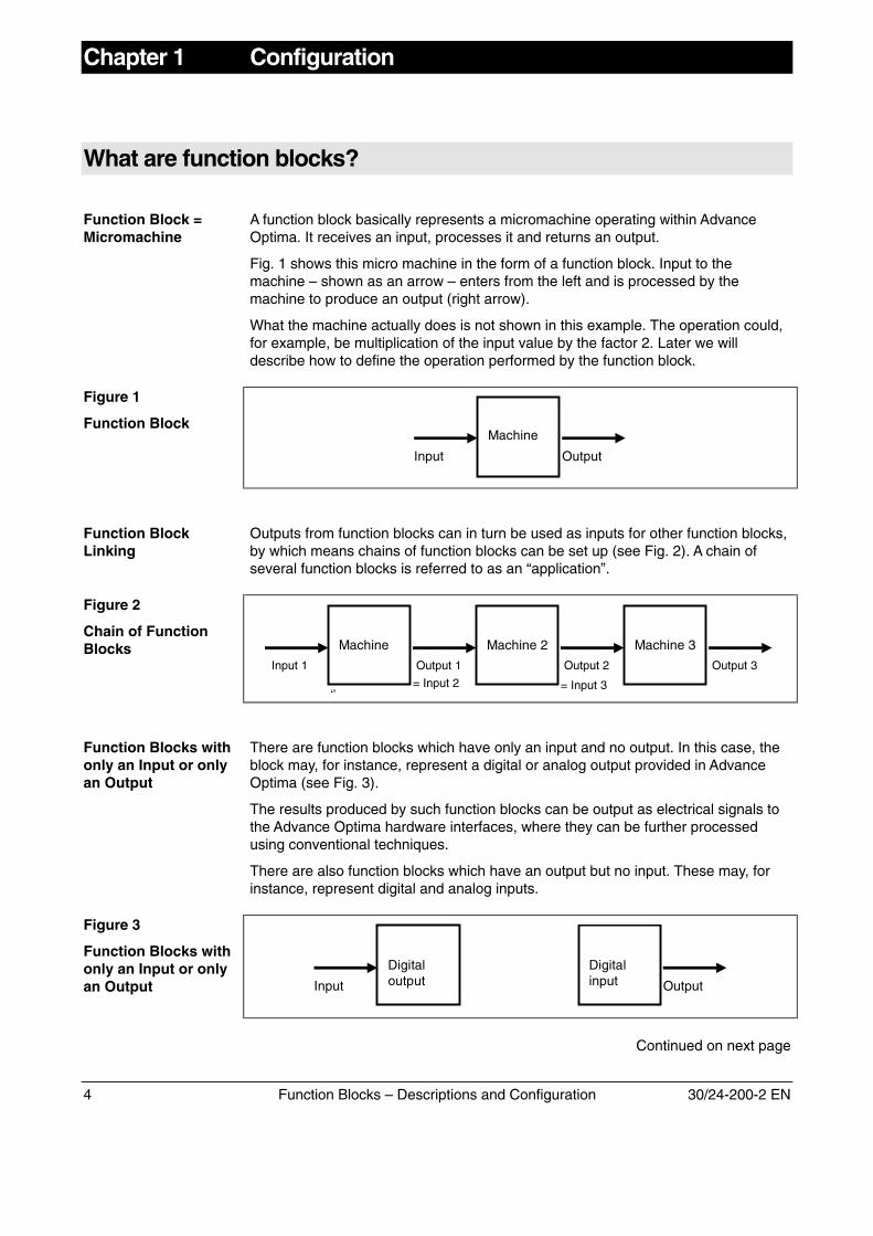
Function Block =Micromachine
A function block basically represents a micromachine operating within AdvanceOptima. It receives an input, processes it and returns an output.
Fig. 1 shows this micro machine in the form of a function block. Input to themachine – shown as an arrow – enters from the left and is processed by themachine to produce an output (right arrow).
What the machine actually does is not shown in this example. The operation could,for example, be multiplication of the input value by the factor 2. Later we willdescribe how to define the operation performed by the function block.
Figure 1
Function BlockMachine
Input Output
Function BlockLinking
Outputs from function blocks can in turn be used as inputs for other function blocks,by which means chains of function blocks can be set up (see Fig. 2). A chain ofseveral function blocks is referred to as an “application”.
Figure 2
Chain of FunctionBlocks 1Machine
‘’
Input 1 Output 1
= Input 2
Machine 3Machine 2
Output 2
= Input 3
Output 3
Function Blocks withonly an Input or onlyan Output
There are function blocks which have only an input and no output. In this case, theblock may, for instance, represent a digital or analog output provided in AdvanceOptima (see Fig. 3).
The results produced by such function blocks can be output as electrical signals tothe Advance Optima hardware interfaces, where they can be further processedusing conventional techniques.
There are also function blocks which have an output but no input. These may, forinstance, represent digital and analog inputs.
Figure 3
Function Blocks withonly an Input or onlyan Output
Digitalinput OutputInput
Digitaloutput
Continued on next page
30/24-200-2 EN Function Blocks – Descriptions and Configuration 5
What are function blocks?, continued
Conventions There are certain conventions applied in the depiction of function blocks. Inputs tothe function blocks are always drawn as arrows coming from the left; outputs comeout of the function block to the right. This clarity of flow direction makes it possible todispense with arrows in many cases and draw simple lines instead.
Arrows = Movementof Information
The arrows or connections transfer analog, binary and decimal information, i.e.arrows and connections correspond to different types of information. Attentionshould therefore be paid to which arrows are linked with which inputs.
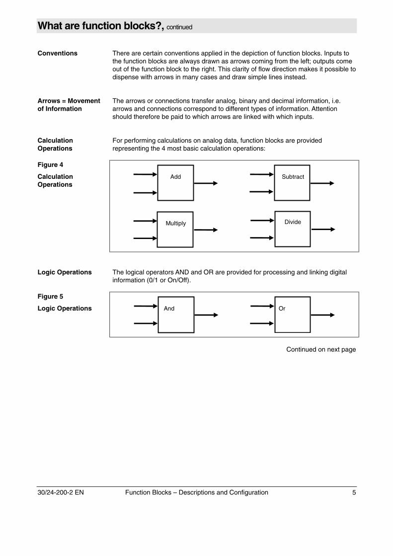
CalculationOperations
For performing calculations on analog data, function blocks are providedrepresenting the 4 most basic calculation operations:
Figure 4
CalculationOperations
Subtract
Multiply Divide
Add
Logic Operations The logical operators AND and OR are provided for processing and linking digitalinformation (0/1 or On/Off).
Figure 5
Logic Operations OrAnd
Continued on next page
6 Function Blocks – Descriptions and Configuration 30/24-200-2 EN
What are function blocks?, continued
Measured Valuesfrom AnalyzerModules
Until now only those function blocks have been presented which present a link tooutside and which can process this information internally. Until now we have notbeen able to integrate measured values and other data with the available functionblocks.
The measured value can probably be described as the most important data item.The measured value is received via the Component measured value functionblock. At system startup time these function blocks are generated automaticallyaccording to the configuration of the analyzers and the number of measuredcomponents.
The Component measured value function block to an Analog input. This functionblock is not, however, linked with a physical input, but receives its values internallyfrom the appropriate analyzer module.
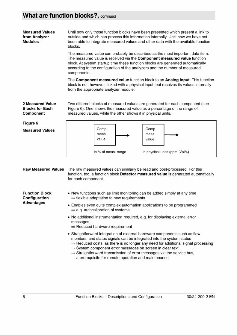
2 Measured ValueBlocks for EachComponent
Two different blocks of measured values are generated for each component (seeFigure 6). One shows the measured value as a percentage of the range ofmeasured values, while the other shows it in physical units.
Figure 6
Measured Values Comp.Mmeas.
value
Comp.measvalue
in % of meas. range in physical units (ppm, Vol%)
Raw Measured Values The raw measured values can similarly be read and post-processed. For thisfunction, too, a function block Detector measured value is generated automaticallyfor each component.
Function BlockConfigurationAdvantages
• New functions such as limit monitoring can be added simply at any time⇒ flexible adaptation to new requirements
• Enables even quite complex automation applications to be programmed
⇒ e.g. autocalibration of systems • No additional instrumentation required, e.g. for displaying external error
messages⇒ Reduced hardware requirement
• Straightforward integration of external hardware components such as flow
monitors, and status signals can be integrated into the system status⇒ Reduced costs, as there is no longer any need for additional signal processing⇒ System component error messages on screen in clear text⇒ Straightforward transmission of error messages via the service bus,
a prerequisite for remote operation and maintenance
30/24-200-2 EN Function Blocks – Descriptions and Configuration 7
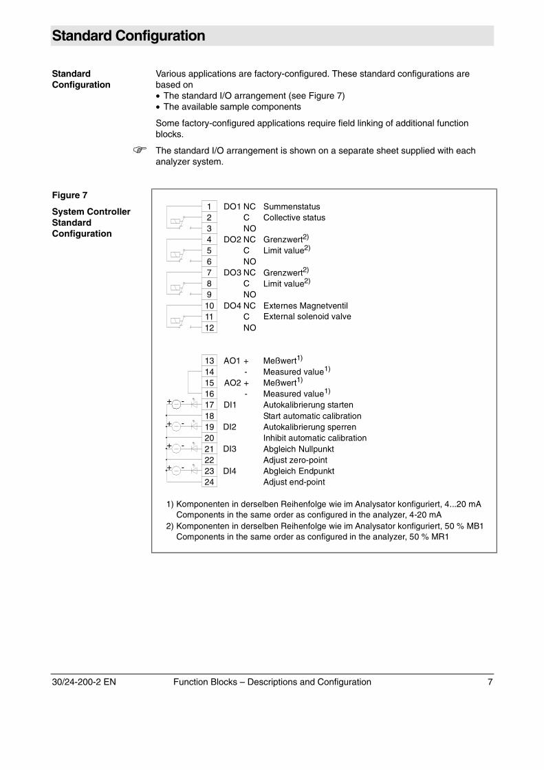
Standard Configuration
StandardConfiguration
Various applications are factory-configured. These standard configurations arebased on• The standard I/O arrangement (see Figure 7)• The available sample components
Some factory-configured applications require field linking of additional functionblocks.
� The standard I/O arrangement is shown on a separate sheet supplied with eachanalyzer system.
Figure 7
System ControllerStandardConfiguration
123456789101112
DO1 NCCNO
DO2 NCCNO
DO3 NCCNO
DO4 NCCNO
AO1 +-
AO2 +-
DI1
DI2
DI3
DI4
131415161718192021222324
-+
-+
-+
-+
1) Komponenten in derselben Reihenfolge wie im Analysator konfiguriert, 4...20 mA Components in the same order as in the analyzer, 4-20 mAconfigured 1)
Meßwert1)
Meßwert1)
Autokalibrierung starten
Autokalibrierung sperren
Abgleich Nullpunkt
Abgleich Endpunkt
Measured value1)
Measured value1)
Start automatic calibration
Inhibit automatic calibration
Adjust zero-point
Adjust end-point
Externes MagnetventilExternal solenoid valve
2) Komponenten in derselben Reihenfolge wie im Analysator konfiguriert, 50 % MB1 Components in the same order as in the analyzer, 50 % MR1configured 2)
Summenstatus
Grenzwert2)
Grenzwert2)
Collective status
Limit value2)
Limit value2)
8 Function Blocks – Descriptions and Configuration 30/24-200-2 EN
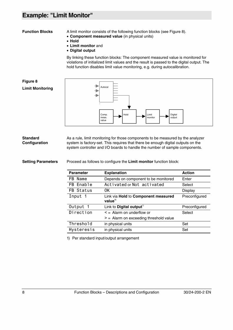
Example: "Limit Monitor"
Function Blocks A limit monitor consists of the following function blocks (see Figure 8).• Component measured value (in physical units)• Hold• Limit monitor and• Digital output
By linking these function blocks: The component measured value is monitored forviolations of initialized limit values and the result is passed to the digital output. Thehold function disables limit value monitoring, e.g. during autocalibration.
Figure 8
Limit Monitoring
Limitmonitor
Comp.meas.value
Digitaloutput
Hold
Autocal
‘’
StandardConfiguration
As a rule, limit monitoring for those components to be measured by the analyzersystem is factory-set. This requires that there be enough digital outputs on thesystem controller and I/O boards to handle the number of sample components.
Setting Parameters Proceed as follows to configure the Limit monitor function block:
Parameter Explanation Action
���� Depends on component to be monitored Enter
������ ������� � or ���������� � Select
������� �� Display
������ Link via Hold to Component measuredvalue1)
Preconfigured
������� Link to Digital output1) Preconfigured
��� ����� � = Alarm on underflow or� = Alarm on exceeding threshold value
Select
!� �!��� in physical units Set
"��� � ��� in physical units Set
1) Per standard input/output arrangement
30/24-200-2 EN Function Blocks – Descriptions and Configuration 9
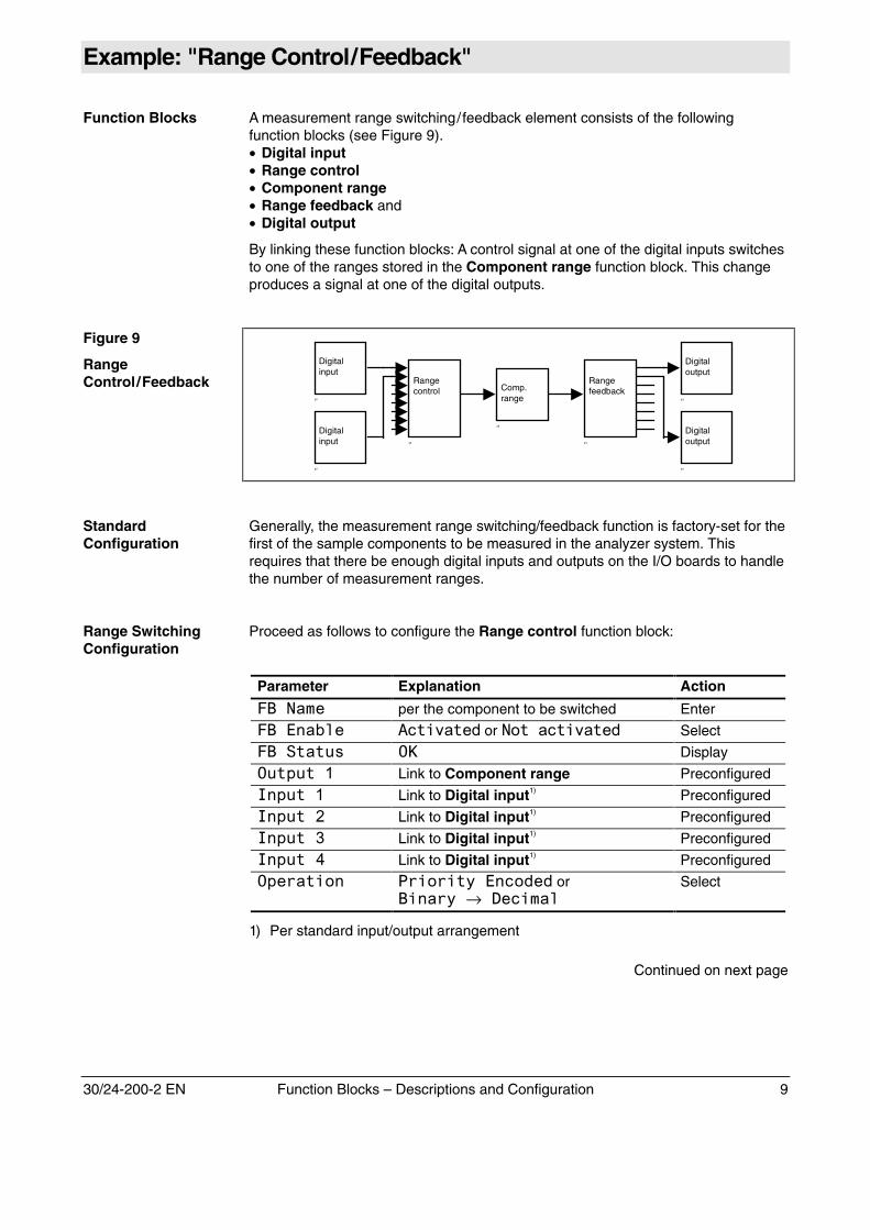
Example: "Range Control/Feedback"
Function Blocks A measurement range switching/feedback element consists of the followingfunction blocks (see Figure 9).• Digital input• Range control• Component range• Range feedback and• Digital output
By linking these function blocks: A control signal at one of the digital inputs switchesto one of the ranges stored in the Component range function block. This changeproduces a signal at one of the digital outputs.
Figure 9
RangeControl/Feedback Range
control
‘’
Rangefeedback
‘’
Digitaloutput
‘’
Comp.range
‘’
Digitalinput
‘’
Digitalinput
‘’
Digitaloutput
‘’
StandardConfiguration
Generally, the measurement range switching/feedback function is factory-set for thefirst of the sample components to be measured in the analyzer system. Thisrequires that there be enough digital inputs and outputs on the I/O boards to handlethe number of measurement ranges.
Range SwitchingConfiguration
Proceed as follows to configure the Range control function block:
Parameter Explanation Action
���� per the component to be switched Enter
������ ������� � or ���������� � Select
������� �� Display
������� Link to Component range Preconfigured
������ Link to Digital input1) Preconfigured
�����# Link to Digital input1) Preconfigured
�����$ Link to Digital input1) Preconfigured
�����% Link to Digital input1) Preconfigured
�� ������ &������������ � or�����→� �����
Select
1) Per standard input/output arrangement
Continued on next page
10 Function Blocks – Descriptions and Configuration 30/24-200-2 EN
Example: "Range Control/Feedback", continued
Range FeedbackConfiguration
Proceed as follows to configure the Range Feedback function block:
Parameter Explanation Action
���� per the component to be reported Enter
������ ������� � or ���������� � Select
������� �� Display
������ Link to Component range Preconfigured
������� Link to Digital output1) Preconfigured
������# Link to Digital output1) Preconfigured
������$ Link to Digital output1) Preconfigured
������% Link to Digital output1) Preconfigured
�� ������ &�������� ��� �or� �����→�����
Select
1) Per standard input/output arrangement
Signal Level A Low → High edge signal at the corresponding digital input is required to controlrange switching. Make sure the signal appears at only one digital input.
The measurement range selected is reported by means of a high signal sent to theapplicable digital output.
Low Level 0–5 V, High Level 8–24 V
30/24-200-2 EN Function Blocks – Descriptions and Configuration 11
Function Block Linking and Initializing
Configurationplanning
Before starting a configuration we recommend using a chart to plan the functionblocks needed for the application to be configured and how the inputs and outputsare linked.
Hardware requirements, e.g. the number of installed and available input and outputterminals, need to be considered.
CAUTION!
The access level 3 password (default: 325465) must be entered in order toconfigure an application. Make sure that existing application configurationsand links are not damaged or deleted when configuring.
Function Block MenuDisplay
When the function blocks to be linked are selected, only those function blockseligible for linking are shown; all other function blocks are represented by '''.
Softkeys The following specific softkeys are displayed when an input or output is selectedduring function block configuration.
DELETELINK
The ��(� �(��� softkey allows the operator to remove any links from theselected input or output.
The �� softkey switches the operator directly to the function block linked to theinput or output selected.
Explanation ofIndividual Parameters
Some parameters apply to every function block. There are explained below.
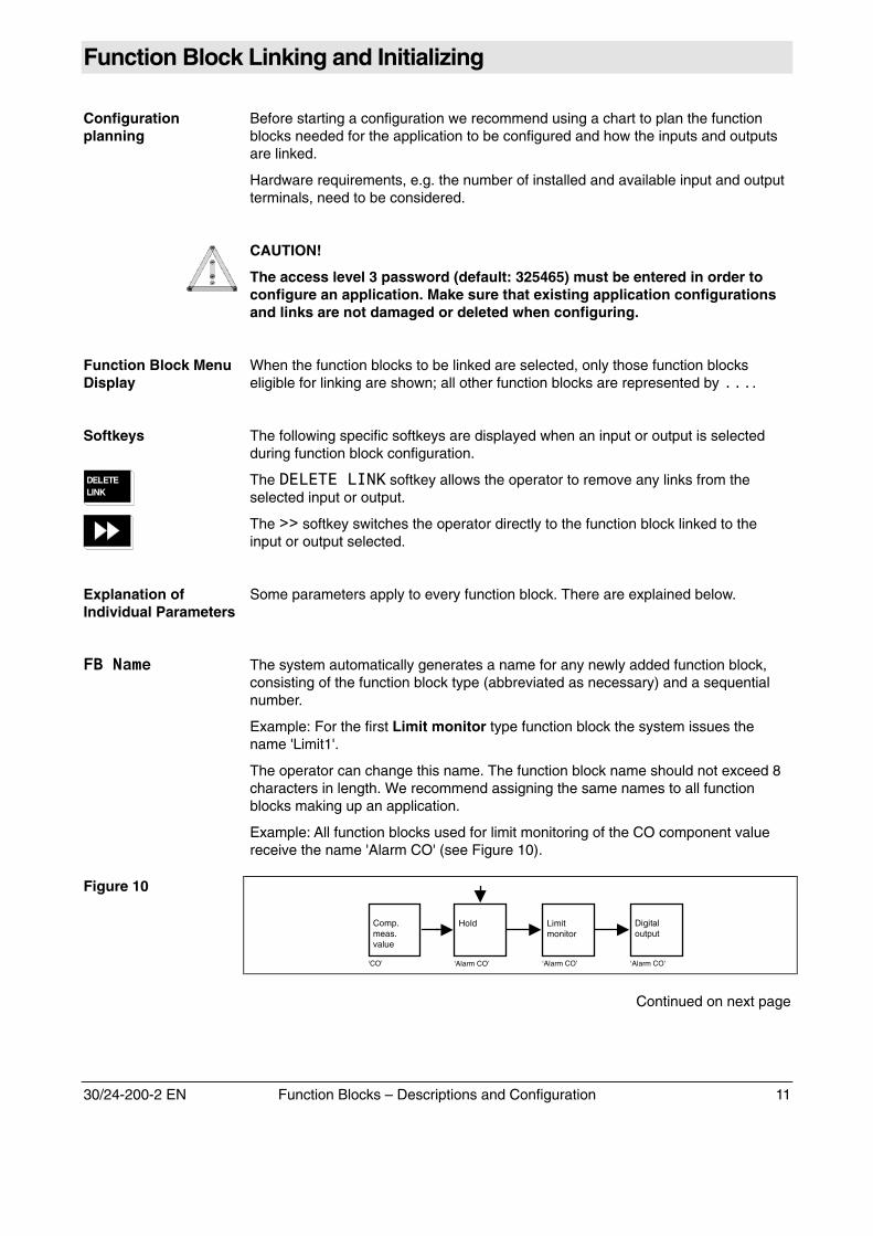
����� The system automatically generates a name for any newly added function block,consisting of the function block type (abbreviated as necessary) and a sequentialnumber.
Example: For the first Limit monitor type function block the system issues thename 'Limit1'.
The operator can change this name. The function block name should not exceed 8characters in length. We recommend assigning the same names to all functionblocks making up an application.
Example: All function blocks used for limit monitoring of the CO component valuereceive the name 'Alarm CO' (see Figure 10).
Figure 10
Limitmonitor
‘Alarm CO’
Comp.meas.value
‘CO’
Digitaloutput
‘Alarm CO’
Hold
‘Alarm CO’
Continued on next page
12 Function Blocks – Descriptions and Configuration 30/24-200-2 EN
Function Block Linking and Initializing, continued
��� ���� The ������ parameter allows the operator to select whether the functionblock is activated or not.
Normally the value is set to ������� �.
������� The �)��� parameter shows the current function block value.
Example: The Digital output function block uses the �)��� parameter toindicate whether the output is �� or �**.
�������� The ������� parameter shows the current function block status.
Normally the value is set to ��. Any other indication is a sign of an error in thefunction block.
�������� The "+������ parameter shows the current status of hardware connected tothe function block, e.g. an analog output.
Normally the value is set to ��. Any other indication is a sign of an error in thehardware associated with the function block, e.g. an open line on an analog output.
������������� A function block's ����� and ������ parameters identify the input and outputlinks to another function block.
Additionally, the value or status of the linked function block input or output is shown.
Example (refer to Figure 10):Display at Output 1 of the Limit monitor function block:
��,�����-�,�Number of the input of the linked function blockName of the linked function blockType of the linked function block
Plain text: Limit monitor function block output 1 is linked to input 1 of a Digitaloutput-type (DO) function block named 'Alarm CO'.
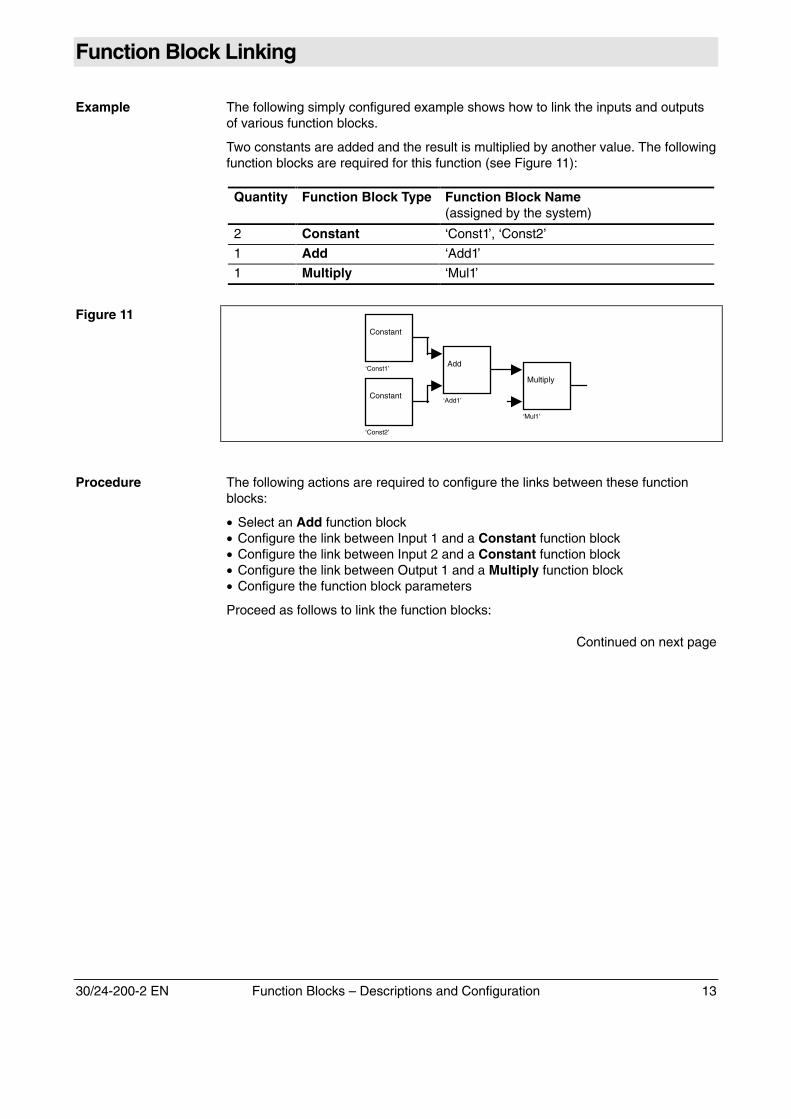
30/24-200-2 EN Function Blocks – Descriptions and Configuration 13
Function Block Linking
Example The following simply configured example shows how to link the inputs and outputsof various function blocks.
Two constants are added and the result is multiplied by another value. The followingfunction blocks are required for this function (see Figure 11):
Quantity Function Block Type Function Block Name(assigned by the system)
2 Constant ‘Const1’, ‘Const2’
1 Add ‘Add1’
1 Multiply ‘Mul1’
Figure 11
Constant
‘Const2’
Constant
‘Const1’Add
‘Add1’
Multiply
‘Mul1’
Procedure The following actions are required to configure the links between these functionblocks:
• Select an Add function block• Configure the link between Input 1 and a Constant function block• Configure the link between Input 2 and a Constant function block• Configure the link between Output 1 and a Multiply function block• Configure the function block parameters
Proceed as follows to link the function blocks:
Continued on next page
14 Function Blocks – Descriptions and Configuration 30/24-200-2 EN
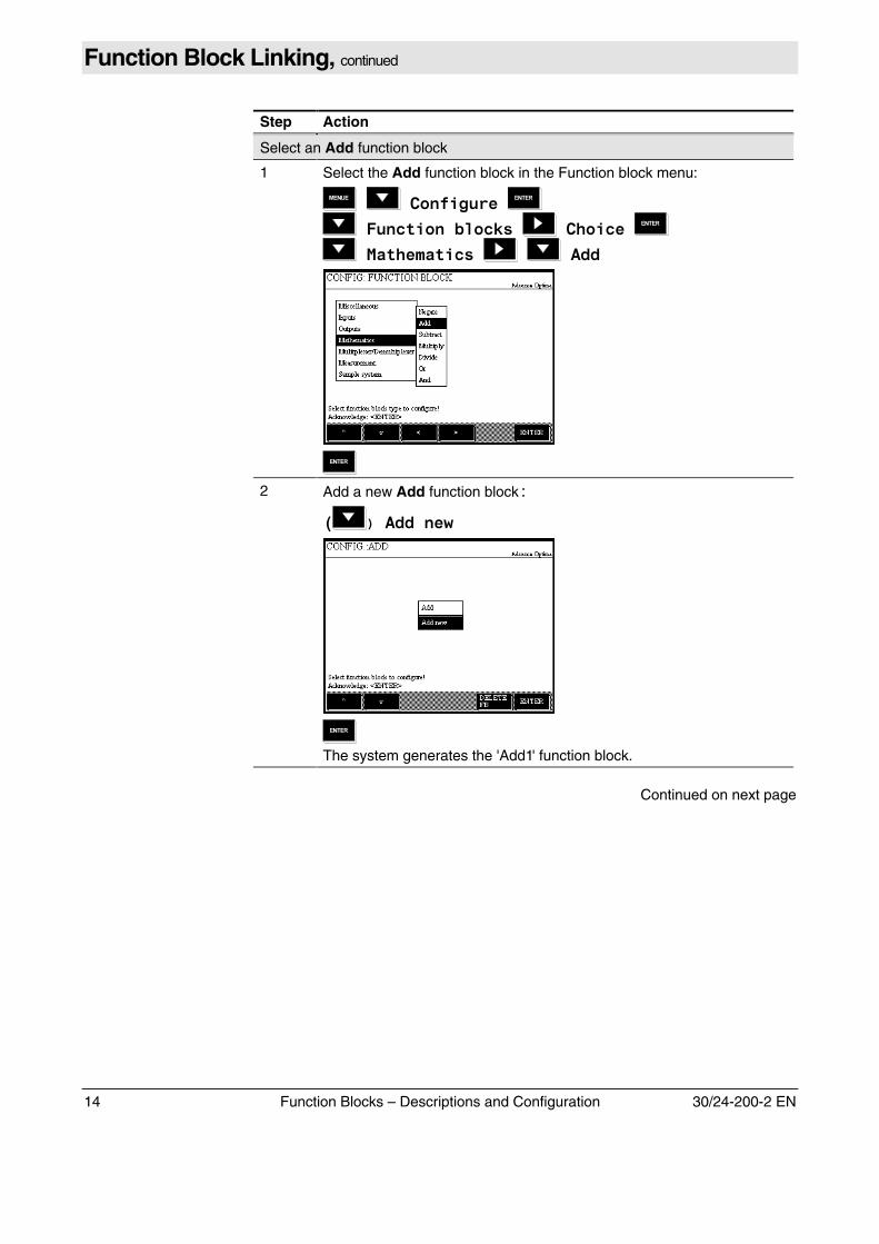
Function Block Linking, continued
Step Action
Select an Add function block
1 Select the Add function block in the Function block menu:
� �����������
����������������� ��������
� ��������� � �!""
2 Add a new Add function block,
# )�!""���$
The system generates the 'Add1' function block.
Continued on next page
30/24-200-2 EN Function Blocks – Descriptions and Configuration 15
Function Block Linking, continued
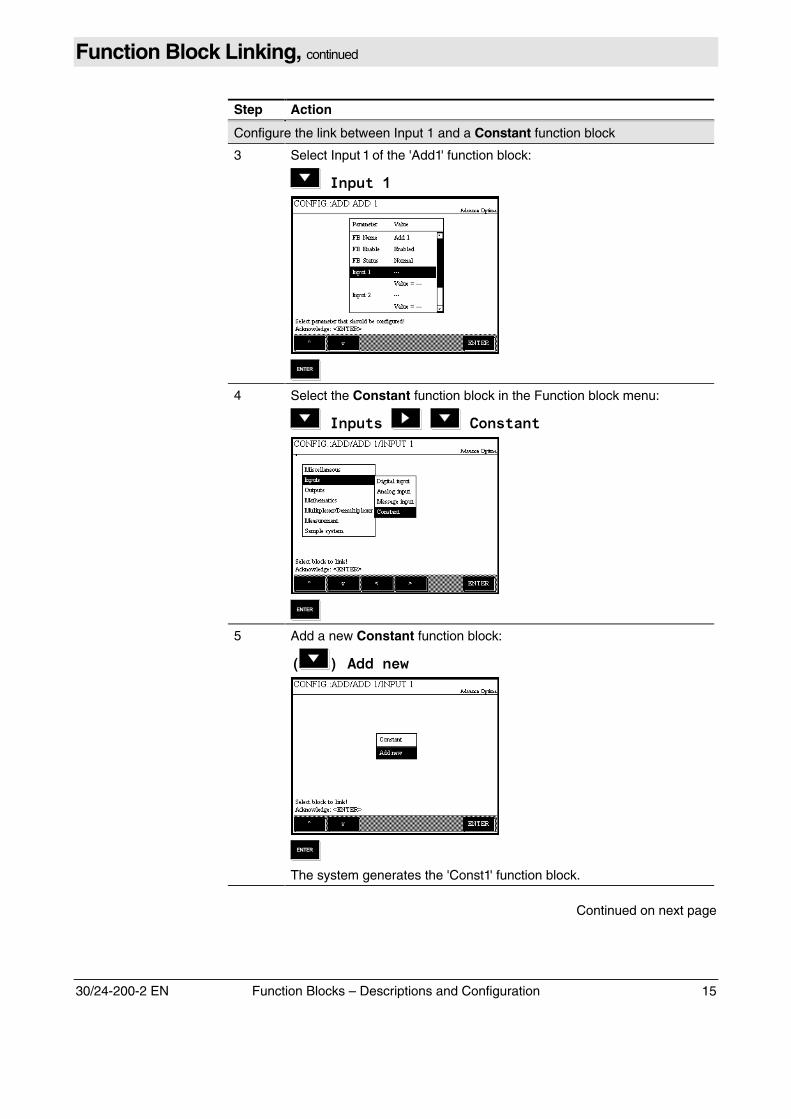
Step Action
Configure the link between Input 1 and a Constant function block
3 Select Input 1 of the 'Add1' function block:
�������%
4 Select the Constant function block in the Function block menu:
�������� � ��������
5 Add a new Constant function block:
# &�!""���$
The system generates the 'Const1' function block.
Continued on next page
16 Function Blocks – Descriptions and Configuration 30/24-200-2 EN
Function Block Linking, continued
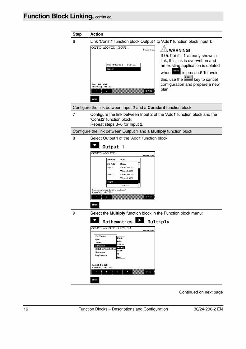
Step Action
6 Link 'Const1' function block Output 1 to 'Add1' function block Input 1:
WARNING!If ������� already shows alink, this link is overwritten andan existing application is deleted
when is pressed! To avoid
this, use the key to cancelconfiguration and prepare a newplan.
Configure the link between Input 2 and a Constant function block
7 Configure the link between Input 2 of the ‘Add1’ function block and the‘Const2’ function block:Repeat steps 3–6 for Input 2.
Configure the link between Output 1 and a Multiply function block
8 Select Output 1 of the 'Add1' function block:
��������%
9 Select the Multiply function block in the Function block menu:
� ��������� � ������'
Continued on next page
30/24-200-2 EN Function Blocks – Descriptions and Configuration 17
Function Block Linking, continued
Step Action
10 Add a new Multiply function block,
# &�!""���$
The system generates the 'Mul1' function block.
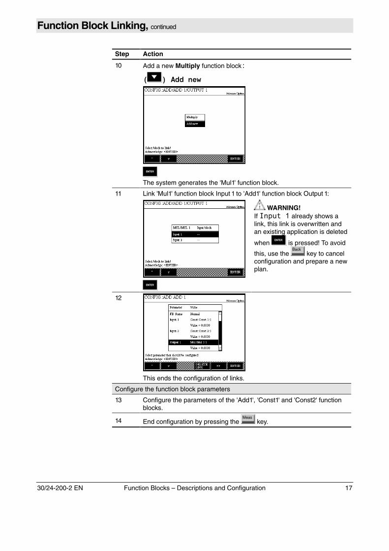
11 Link 'Mul1' function block Input 1 to 'Add1' function block Output 1:
WARNING!If ������ already shows alink, this link is overwritten andan existing application is deleted
when is pressed! To avoid
this, use the key to cancelconfiguration and prepare a newplan.
12
This ends the configuration of links.
Configure the function block parameters
13 Configure the parameters of the 'Add1', 'Const1' and 'Const2' functionblocks.
14 End configuration by pressing the key.
18 Function Blocks – Descriptions and Configuration 30/24-200-2 EN
Chapter 2 Descriptions
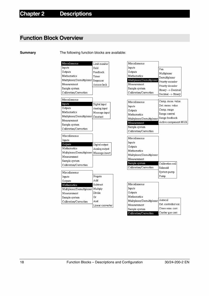
Function Block Overview
Summary The following function blocks are available:
30/24-200-2 EN Function Blocks – Descriptions and Configuration 19
Limit Monitor
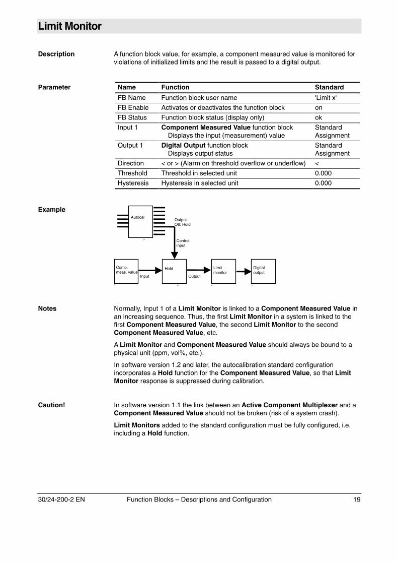
Description A function block value, for example, a component measured value is monitored forviolations of initialized limits and the result is passed to a digital output.
Parameter Name Function Standard
FB Name Function block user name 'Limit x'
FB Enable Activates or deactivates the function block on
FB Status Function block status (display only) ok
Input 1 Component Measured Value function blockDisplays the input (measurement) value
StandardAssignment
Output 1 Digital Output function blockDisplays output status
StandardAssignment
Direction < or > (Alarm on threshold overflow or underflow) <
Threshold Threshold in selected unit 0.000
Hysteresis Hysteresis in selected unit 0.000
Example
Limitmonitor
‘’
Digitaloutput
‘’
Hold
‘’
Comp.meas. value
‘’
Input Output
Controlinput
Autocal
‘’
OutputO6: Hold
Notes Normally, Input 1 of a Limit Monitor is linked to a Component Measured Value inan increasing sequence. Thus, the first Limit Monitor in a system is linked to thefirst Component Measured Value, the second Limit Monitor to the secondComponent Measured Value, etc.
A Limit Monitor and Component Measured Value should always be bound to aphysical unit (ppm, vol%, etc.).
In software version 1.2 and later, the autocalibration standard configurationincorporates a Hold function for the Component Measured Value, so that LimitMonitor response is suppressed during calibration.
Caution! In software version 1.1 the link between an Active Component Multiplexer and aComponent Measured Value should not be broken (risk of a system crash).
Limit Monitors added to the standard configuration must be fully configured, i.e.including a Hold function.
20 Function Blocks – Descriptions and Configuration 30/24-200-2 EN
Hold
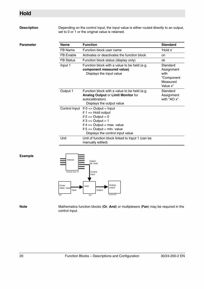
Description Depending on the control input, the input value is either routed directly to an output,set to 0 or 1 or the original value is retained.
Parameter Name Function Standard
FB Name Function block user name 'Hold x'
FB Enable Activates or deactivates the function block on
FB Status Function block status (display only) ok
Input 1 Function block with a value to be held (e.g.component measured value)
Displays the input value
StandardAssignmentwith"ComponentMeasuredValue x"
Output 1 Function block with a value to be held (e.g.Analog Output or Limit Monitor forautocalibration)
Displays the output value
StandardAssignmentwith "AO x"
Control Input If 0 => Output = Inputif 1 => Hold outputif 2 => Output = 0if 3 => Output = 1if 4 => Output = max. valueif 5 => Output = min. value
Displays the control input value
Unit Unit of function block linked to Input 1 (can bemanually edited)
Example
Analogoutput
‘A Out CO’
Hold
‘CO’
Comp.meas. value
‘CO’
Input Output
Controlinput
Autocal
‘Autocal Uras 14’
OutputO6: Hold
Note Mathematics function blocks (Or, And) or multiplexers (Fan) may be required in thecontrol input.
30/24-200-2 EN Function Blocks – Descriptions and Configuration 21
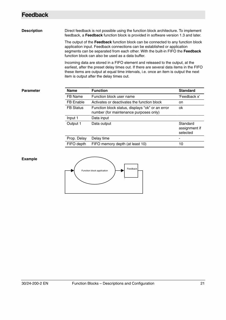
Feedback
Description Direct feedback is not possible using the function block architecture. To implementfeedback, a Feedback function block is provided in software version 1.3 and later.
The output of the Feedback function block can be connected to any function blockapplication input. Feedback connections can be established or applicationsegments can be separated from each other. With the built-in FIFO the Feedbackfunction block can also be used as a data buffer.
Incoming data are stored in a FIFO element and released to the output, at theearliest, after the preset delay times out. If there are several data items in the FIFOthese items are output at equal time intervals, i.e. once an item is output the nextitem is output after the delay times out.
Parameter Name Function Standard
FB Name Function block user name 'Feedback x'
FB Enable Activates or deactivates the function block on
FB Status Function block status, displays "ok" or an errornumber (for maintenance purposes only)
ok
Input 1 Data input
Output 1 Data output Standardassignment ifselected
Prop. Delay Delay time -
FIFO depth FIFO memory depth (at least 10) 10
Example
Feedback
‘’
Function block application
22 Function Blocks – Descriptions and Configuration 30/24-200-2 EN
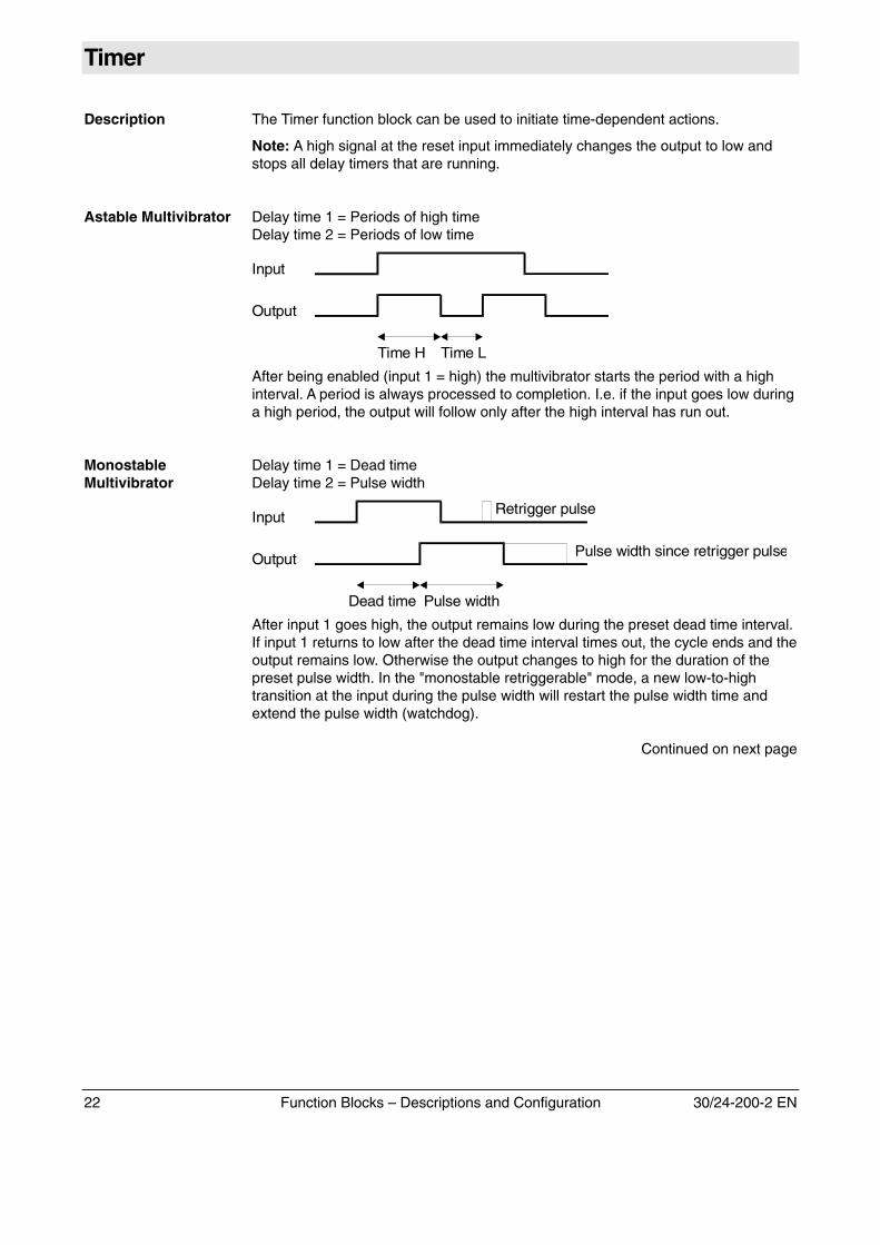
Timer
Description The Timer function block can be used to initiate time-dependent actions.
Note: A high signal at the reset input immediately changes the output to low andstops all delay timers that are running.
Astable Multivibrator Delay time 1 = Periods of high timeDelay time 2 = Periods of low time
Time H Time L
Input
Output
After being enabled (input 1 = high) the multivibrator starts the period with a highinterval. A period is always processed to completion. I.e. if the input goes low duringa high period, the output will follow only after the high interval has run out.
MonostableMultivibrator
Delay time 1 = Dead timeDelay time 2 = Pulse width
Dead time Pulse width
Output
Input Retrigger pulse
Pulse width since retrigger pulse
After input 1 goes high, the output remains low during the preset dead time interval.If input 1 returns to low after the dead time interval times out, the cycle ends and theoutput remains low. Otherwise the output changes to high for the duration of thepreset pulse width. In the "monostable retriggerable" mode, a new low-to-hightransition at the input during the pulse width will restart the pulse width time andextend the pulse width (watchdog).
Continued on next page
30/24-200-2 EN Function Blocks – Descriptions and Configuration 23
Timer, continued
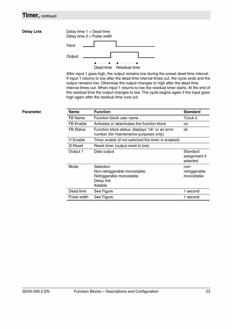
Delay Link Delay time 1 = Dead timeDelay time 2 = Pulse width
Input
Output
Dead time Residual time
After input 1 goes high, the output remains low during the preset dead time interval.If input 1 returns to low after the dead time interval times out, the cycle ends and theoutput remains low. Otherwise the output changes to high after the dead timeinterval times out. When input 1 returns to low the residual timer starts. At the end ofthe residual time the output changes to low. The cycle begins again if the input goeshigh again after the residual time runs out.
Parameter Name Function Standard
FB Name Function block user name 'Clock x'
FB Enable Activates or deactivates the function block on
FB Status Function block status, displays "ok" or an errornumber (for maintenance purposes only)
ok
I1:Enable Timer enable (if not switched the timer is enabled)
I2:Reset Reset timer (output reset to low)
Output 1 Data output Standardassignment ifselected
Mode Selection:Non-retriggerable monostableRetriggerable monostableDelay linkAstable
non-retriggerablemonostable
Dead time See Figure 1 second
Pulse width See Figure 1 second
Example
24 Function Blocks – Descriptions and Configuration 30/24-200-2 EN
Sequencer
Description The Sequencer function block allows the programming of output sequences.
Each rising or falling edge at the clock input increments the internal programcounter by one and values stored at each program step are released to the outputs.Once the last step is reached the program returns to the first program step after oneclock pulse. A low signal at the enable input causes the clock input to have noeffect.
A high signal at the reset input automatically places the outputs in the reset step, orif this step is not present, sets them low. The step counter is set at program starttime.
The individual program steps are stored in the sequence parameter. The firstprogram step defined is the reset condition (reset step). One of the next programsteps should program only those outputs whose values are to change. Outputs notcovered by a program step will not be changed.
Any digits are allowed as output values.
Parameter Name Function Standard
FB Name Function block user name 'Seqncr x'
FB Enable Activates or deactivates the function block on
FB Status Function block status, displays "ok" or an errornumber (for maintenance purposes only)
ok
Sequence Sequence entry for outputs 1-8 (see example) -
Slope Edge (rising or falling) triggering the transition tothe next step.
Rising
Step No. Display only
I1: Clock Clock input (determines sequence triggering)
I2: Enable Process control enable
I3: Reset Process control reset
Output 1 Programmed sequence output
Output 2 Programmed sequence output
Output 3 Programmed sequence output
Output 4 Programmed sequence output
Output 5 Programmed sequence output
Output 6 Programmed sequence output
Output 7 Programmed sequence output
Output 8 Programmed sequence output
Continued on next page
30/24-200-2 EN Function Blocks – Descriptions and Configuration 25
Sequencer, continued
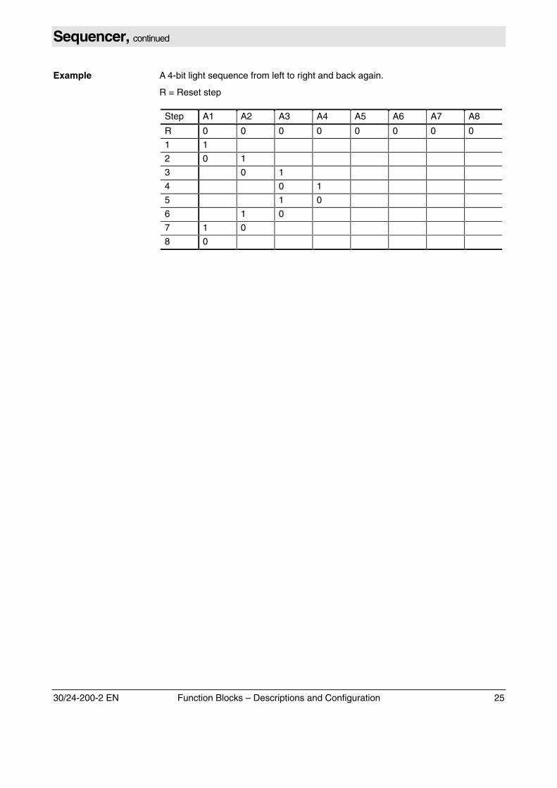
Example A 4-bit light sequence from left to right and back again.
R = Reset step
Step A1 A2 A3 A4 A5 A6 A7 A8
R 0 0 0 0 0 0 0 0
1 1
2 0 1
3 0 1
4 0 1
5 1 0
6 1 0
7 1 0
8 0
26 Function Blocks – Descriptions and Configuration 30/24-200-2 EN
Access Lock
Description Blocks operation at the device, via the remote HMI or both methods. For example,operation via the remote HMI can be locked out using a digital input (to which a keyswitch can be connected).
Parameter Name Function Standard
FB Name Function block user name 'Access lock'
FB Enable Activates or deactivates the function block on
FB Status Function block status (display only) ok
Input 1 Function block with an output value that blocksor permits operation.Input = 0: Operation blockedInput = 1: Operation enabledOperation is permitted if the input is not linked.
Output 1 Status outputIf 0 => Operation blockedIf 1 => Operation enabled
Effect Establishes which type of operation is blocked orenabled:Local HMI => Operation at analyzerRemote HMIs => Operation with remote HMIAll HMIs => Local and remote HMIs
Remote HMIs
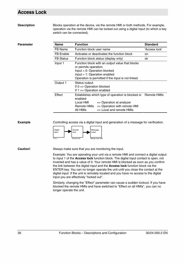
Example Controlling access via a digital input and generation of a message for verification.
Messageinsert
‘Messg insert HMI’
Accesslock
‘Access lock’
Digitalinput
‘D In x ‘
Caution! Always make sure that you are monitoring the input.
Example: You are operating your unit via a remote HMI and connect a digital outputto input 1 of the Access lock function block. The digital input contact is open, notinverted and has a value of 0. Your remote HMI is blocked as soon as you confirmthe link between the digital input and the Access lock function block via theENTER key. You can no longer operate the unit until you close the contact at thedigital input. If the unit is remotely located and you have no access to the digitalinput you are effectively "locked out".
Similarly, changing the "Effect" parameter can cause a sudden lockout: If you haveblocked the remote HMIs and have switched to "Effect on all HMIs", you can nolonger operate the unit.
30/24-200-2 EN Function Blocks – Descriptions and Configuration 27
Digital Input
Description Generated according to the available digital input hardware or the virtual modbusDI. The modbus DIs are assigned to virtual units (no hardware is involved) and canonly be addressed via the modbus interface.
Parameter Name Function Standard
FB Name Function block user name Per standardarrangement
FB Enable Activates or deactivates the function block on
FB Value Current value (display only):"On" or "Off"(Difference between FB Value - FB Status)
Current value
FB Status Function block status, displays "ok" or an errornumber (for maintenance purposes only)
ok
HW Status Hardware status, displays "ok" or an error number(for maintenance purposes only) Example:Display "1024" = Configuration of an I/O notavailable as hardware
ok
Output 1 Function block controlling this Digital input, e.g.Message Insert or Range control
Per standardarrangement
DI No. orAddress
Number of DI on this board or modbus address
Device Board identification (e.g. SYSCON:SYST.CPU) orany text for modbus DI; currently 'Slave'
-
Fail Safe The value to be assumed if the DI fails. Off
Invert Inverts the hardware DI input No
Mode Update operating mode:'Refresh on value change','Query measurement value' or'Cyclical measurement value refresh'
Refresh onvalue change
Dead time Time during which the input should remain stablein order to be acknowledged as a definite level(bounce avoidance)
0 sec.
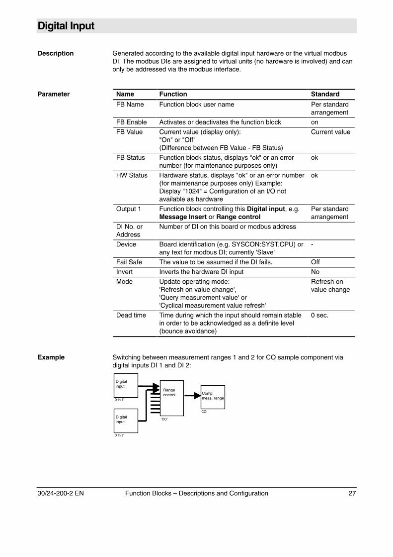
Example Switching between measurement ranges 1 and 2 for CO sample component viadigital inputs DI 1 and DI 2:
Rangecontrol
‘CO’
Comp.meas. range
‘CO’
Digitalinput
‘D In 1’
Digitalinput
‘D In 2’
28 Function Blocks – Descriptions and Configuration 30/24-200-2 EN
Analog Input
Description Generated according to the available analog input hardware or the virtual modbusAI. The modbus AIs are assigned to virtual units (no hardware is involved) and canonly be addressed via the modbus interface.
Parameter Name Function Standard
FB Name Function block user name ‘I In x’
FB Enable Activates or deactivates the function block on
FB Value Current value is displayed
FB Status Function block status, displays "ok" or an errornumber (for maintenance purposes only)
ok
HW Status Hardware status, displays "normal" = ok or anerror number (for maintenance purposes only)Example: Display "1024" = Configuration of I/Osnot available as hardware
-
Output 1 Function block to which the Analog input is tobe assigned, e.g. Linear converter
AI No. Number of the AI on this board -
Device Board identification (e.g. SYSCON:SYST. CPU) -
Fail Safe The value to be assumed if the AI fails. 0.000 mA
Measurement Range
Displays the input span –10 to +10 V–20 to +20 mA
Mode Update operating mode: 'Query measurementvalue' or'Cyclical measurement value refresh'
Query meas.value
Cycle Time 'Cyclical measurement value refresh' interval 1.00 sec.
Resolution Display only 12 bit
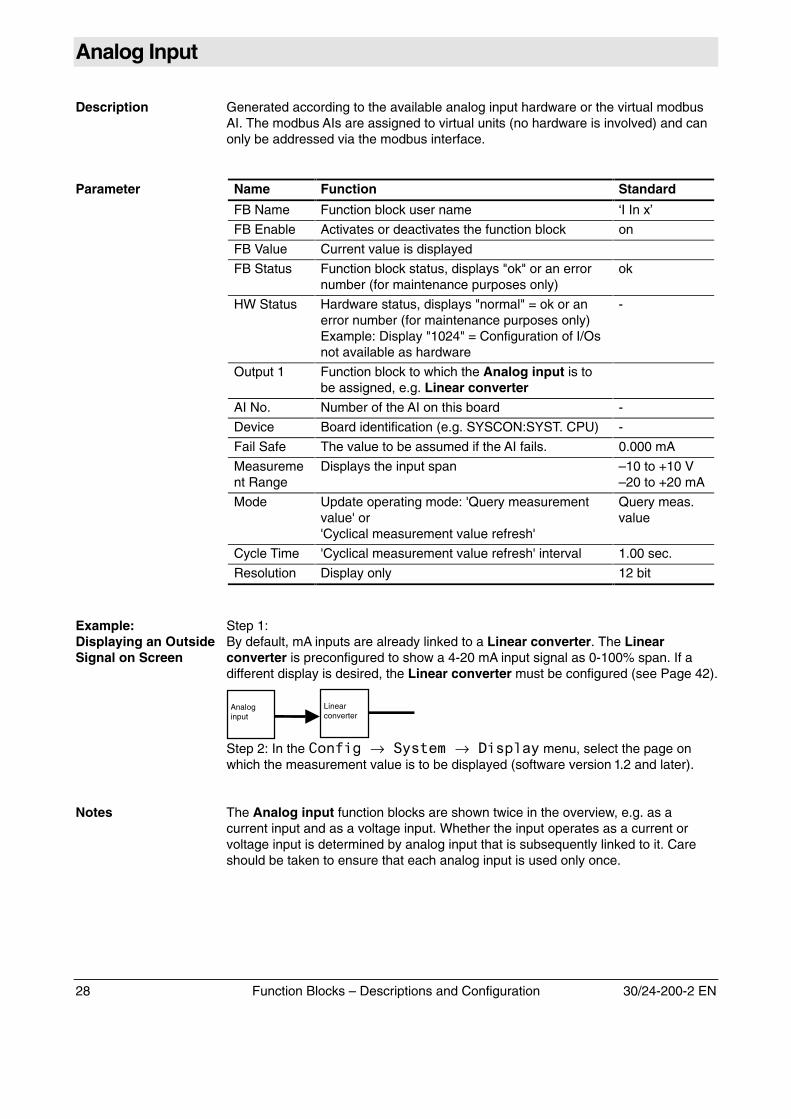
Example:Displaying an OutsideSignal on Screen
Step 1:By default, mA inputs are already linked to a Linear converter. The Linearconverter is preconfigured to show a 4-20 mA input signal as 0-100% span. If adifferent display is desired, the Linear converter must be configured (see Page 42).
Analoginput
Linearconverter
‘Step 2: In the -��*�.→���� �→������� menu, select the page onwhich the measurement value is to be displayed (software version 1.2 and later).
Notes The Analog input function blocks are shown twice in the overview, e.g. as acurrent input and as a voltage input. Whether the input operates as a current orvoltage input is determined by analog input that is subsequently linked to it. Careshould be taken to ensure that each analog input is used only once.
30/24-200-2 EN Function Blocks – Descriptions and Configuration 29
Message Input
Description This block is activated selectively via a system message (e.g. maintenance mode,individual error number). Beginning with software version 1.3 system messages canbe selectively addressed down to the component level. Thus, for example, statusmessages can be sent to a DO or an output signal can be used to enable or disablefunctions within an FB "tree".
Parameter Name Function Standard
FB Name Function block user name 'Message Inputx'
FB Enable Activates or deactivates the function block on
FB Value Corresponds to FB status (0 or 1), depending onwhether its specific system message is active orinactive.
-
FB Status Function block status (display only) ok
Output 1 The function block on which the Message inputshould act, generally a Digital Output.
Configurationrequired
Mode Selection:'Activate on selected message no.''Activate on error''Activate on maintenance required''Activate on maintenance mode'
Activate onselectedmessage no.
Source Selection:System, module, component
System
MessageNo.
If 'activate on selected message no.' is selectedas the mode, the number of the status messagewhich is to activate a message should beentered at this point.
0
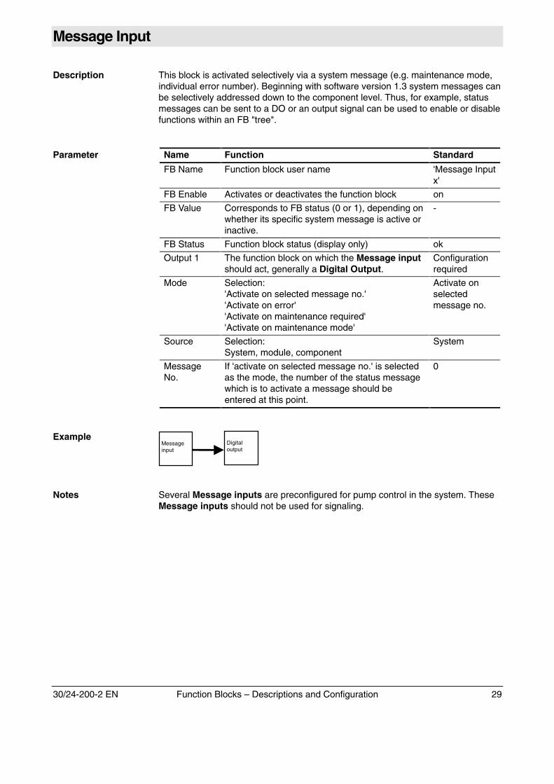
ExampleMessageinput
Digitaloutput
‘
Notes Several Message inputs are preconfigured for pump control in the system. TheseMessage inputs should not be used for signaling.
30 Function Blocks – Descriptions and Configuration 30/24-200-2 EN
Constant
Description The Constant function block can, for example, be used on an Add FB for adding aconstant.
Parameter Name Function Standard
FB Name Function block user name 'Const x'
FB Enable Activates or deactivates the function block on
FB Value Set constant value 0.0000
FB Status Function block status (display only) ok
Output 1 Function block to which the constant is to belinked.
-
Unit Designation of the unit from the function blockconnected to the input, editable
-
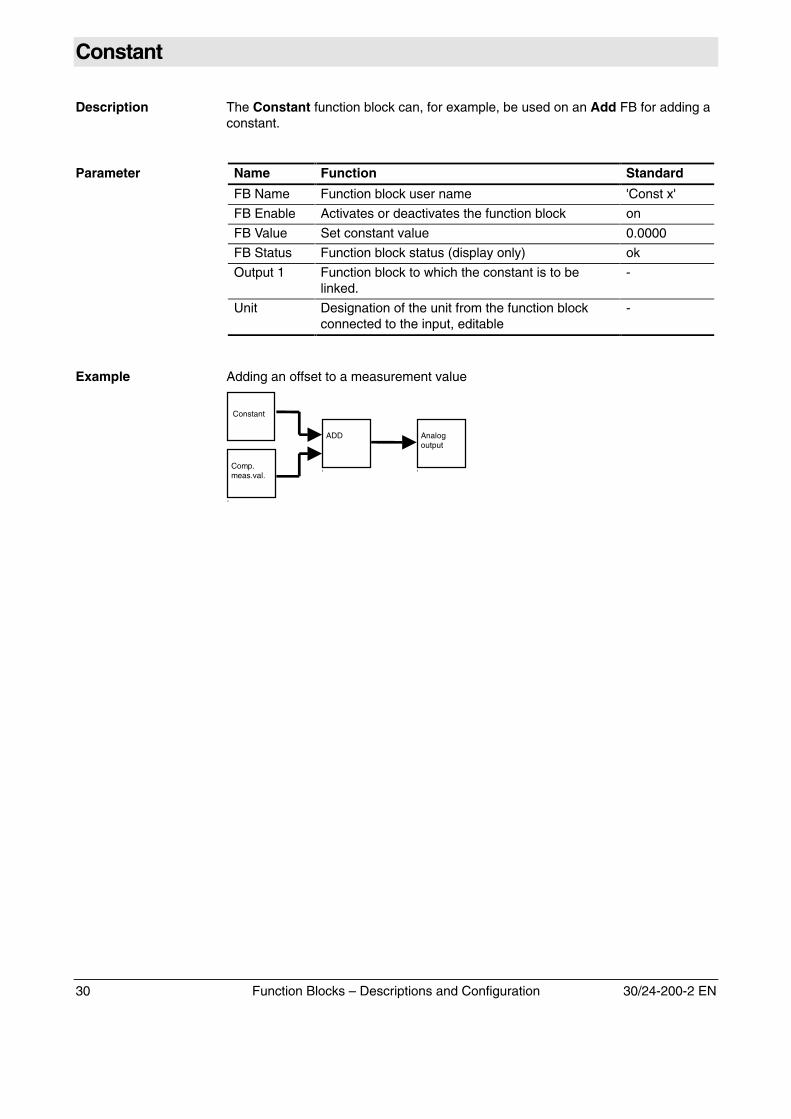
Example Adding an offset to a measurement value
Constant
ADD
‘Comp.meas.val.
‘
Analogoutput
‘
30/24-200-2 EN Function Blocks – Descriptions and Configuration 31
Digital Output
Description Generated according to the available digital output hardware or the virtual modbusDO. The modbus DOs are assigned to virtual units (no hardware is involved) andcan only be addressed via the modbus interface.
Parameter Name Function Standard
FB Name Function block user name ‘D Out x’
FB Enable Activates or deactivates the function block on
FB Value Current output value is displayed -
FB Status Function block status, displays "ok" or an errornumber (for maintenance purposes only)
ok
HW Status Hardware status, displays "normal" = ok or anerror number (for maintenance purposes only)Example: Display "1024" = Configuration of I/Osnot available as hardware
Input 1 Function block for which status is to output, e.g.Range feedback or Limit monitor.
Standardassignment ifselected
DO No. Number of the DO on this board -
Device Board identification (e.g. SYSCON:SYST. CPU) -
Output Type Select "normal" or "pump". By selecting "pump"the output is integrated into the pump controlmaintenance function. This allows simpleoperation of an external pump.
Normal
Fail Safe The value to be assumed if the DO fails. Off
Invert Inverts the hardware DO input No
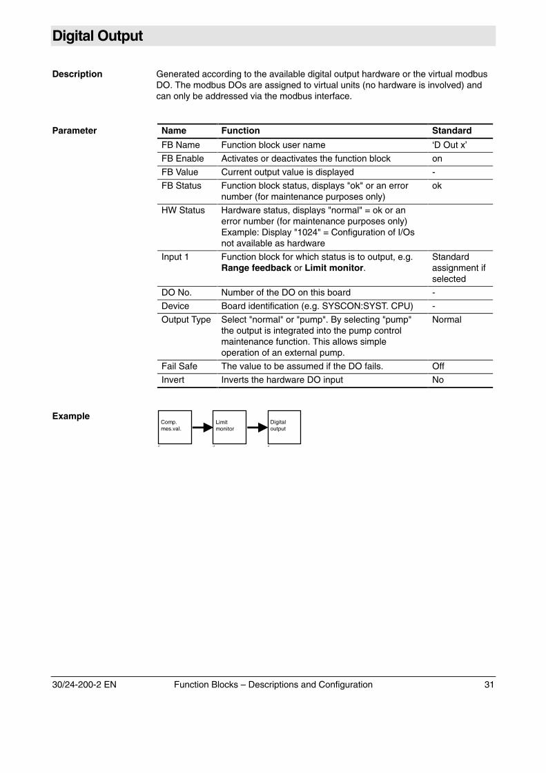
ExampleLimitmonitor
‘’
Comp.mes.val.
‘’
Digitaloutput
‘’
32 Function Blocks – Descriptions and Configuration 30/24-200-2 EN
Analog Output
Description Generated according to the available analog output hardware or the virtual modbusAO. The modbus AOs are assigned to virtual units (no hardware is involved) andcan only be addressed via the modbus interface.
Parameter Name Function Standard
FB Name Function block user name ‘A Out x’
FB Enable Activates or deactivates the function block on
FB Value Current output value is displayed -
FB Status Function block status, displays "ok" or an errornumber (for maintenance purposes only)
ok
HW Status Hardware status, displays "normal" = ok or anerror number (for maintenance purposes only)Example: Display "1024" = Configuration of I/Osnot available as hardwareExample: Display "4096" = No load on analogoutput, e.g. line break
-
Input 1 Function block the value of which is to be output,generally a Component measured value, or aComponent measured value via a Hold FB, ifthe measurement value is to be held duringautocalibration.
StandardAssignment
OutputCurrentRange
0–20, 2–20, 4–20 mA 4-20 mA
Device Board identification (e.g. SYSCON:SYST. CPU) -
AO No. Number of the AO on this board -
Fail Safe The value to be assumed if the input fails. 0 mA
Max.CurrentRange
Determined by hardware 0-22 mA
CurrentStart
User-defined current range 0
Current End User-defined current range 22
RefreshRate
Determined by I/O, factory-configured 0.5 sec.
Resolution Determined by hardware 16 bit
Continued on next page
30/24-200-2 EN Function Blocks – Descriptions and Configuration 33
Analog Output, continued
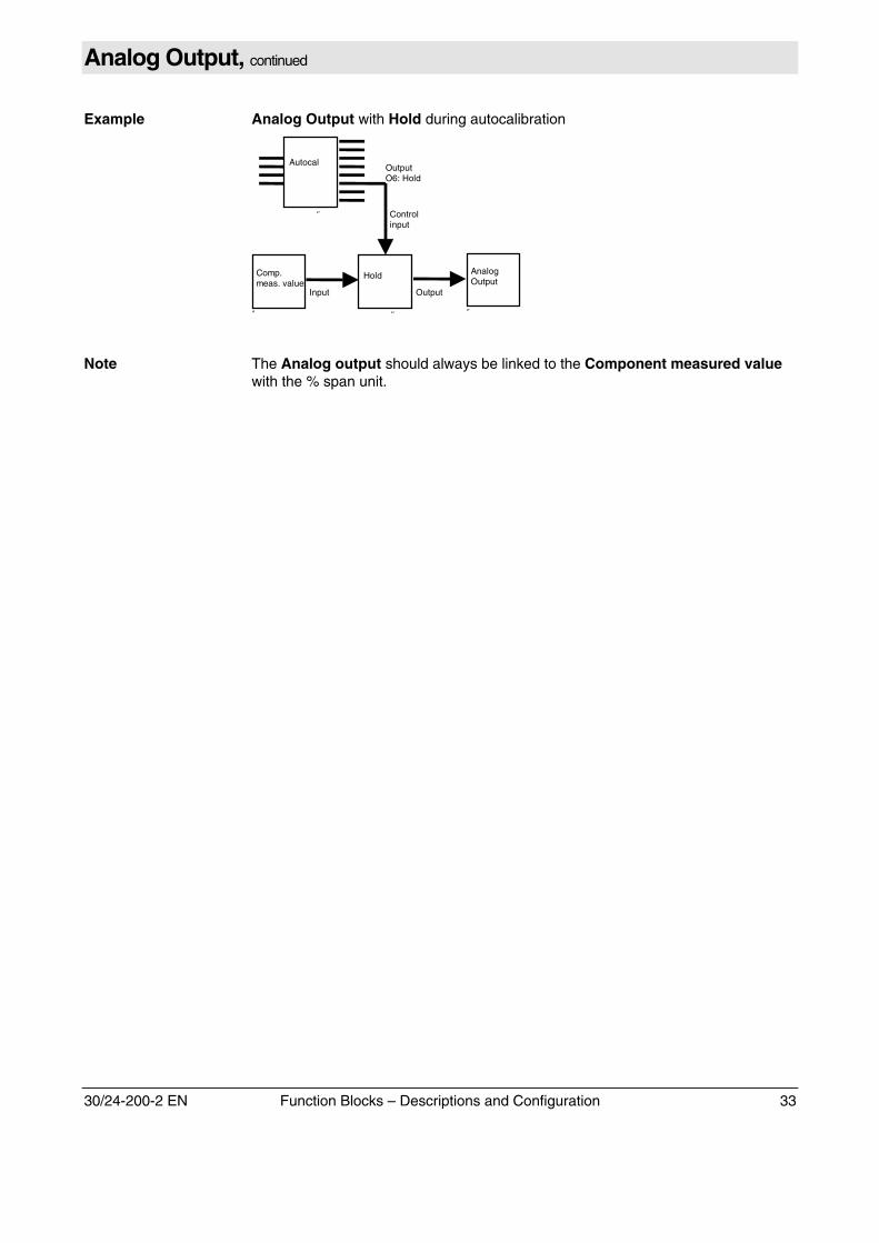
Example Analog Output with Hold during autocalibration
AnalogOutput
‘’
Hold
‘’
Comp.meas. value
‘’
Input Output
Controlinput
Autocal
‘’
OutputO6: Hold
Note The Analog output should always be linked to the Component measured valuewith the % span unit.
34 Function Blocks – Descriptions and Configuration 30/24-200-2 EN
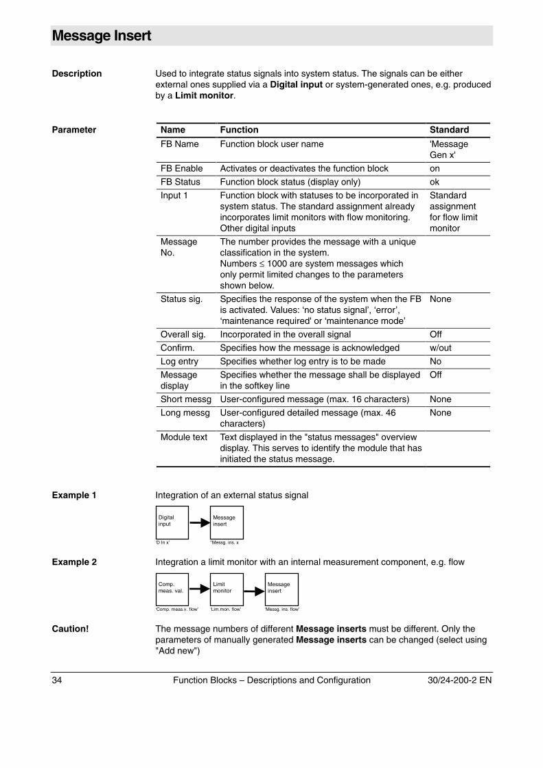
Message Insert
Description Used to integrate status signals into system status. The signals can be eitherexternal ones supplied via a Digital input or system-generated ones, e.g. producedby a Limit monitor.
Parameter Name Function Standard
FB Name Function block user name 'MessageGen x'
FB Enable Activates or deactivates the function block on
FB Status Function block status (display only) ok
Input 1 Function block with statuses to be incorporated insystem status. The standard assignment alreadyincorporates limit monitors with flow monitoring.Other digital inputs
Standardassignmentfor flow limitmonitor
MessageNo.
The number provides the message with a uniqueclassification in the system.Numbers ≤ 1000 are system messages whichonly permit limited changes to the parametersshown below.
Status sig. Specifies the response of the system when the FBis activated. Values: ‘no status signal’, ‘error’,‘maintenance required' or ‘maintenance mode’
None
Overall sig. Incorporated in the overall signal Off
Confirm. Specifies how the message is acknowledged w/out
Log entry Specifies whether log entry is to be made No
Messagedisplay
Specifies whether the message shall be displayedin the softkey line
Off
Short messg User-configured message (max. 16 characters) None
Long messg User-configured detailed message (max. 46characters)
None
Module text Text displayed in the "status messages" overviewdisplay. This serves to identify the module that hasinitiated the status message.
Example 1 Integration of an external status signal
Messageinsert
‘’Messg. ins. x
Digitalinput
‘D In x’
Example 2 Integration a limit monitor with an internal measurement component, e.g. flow
Messageinsert
‘Messg. ins. flow’
Limitmonitor
‘Lim.mon. flow’
Comp.meas. val.
‘Comp. meas.v. flow’
Caution! The message numbers of different Message inserts must be different. Only theparameters of manually generated Message inserts can be changed (select using"Add new")
30/24-200-2 EN Function Blocks – Descriptions and Configuration 35
Negate
Description Boolean negation of input.
Parameter Name Function Standard
FB Name Function block user name 'Neg x'
FB Enable Activates or deactivates the function block on
FB Status Function block status (display only) ok
Unit Assumes the unit from block input 1 as soon as alink with another function block takes place. Thereis no value if no automatic linkage takes place.Can also be edited manually.
Input 1 Function block with value to be negated
Output 1 Function block, on which the negated signal is toact
Example
36 Function Blocks – Descriptions and Configuration 30/24-200-2 EN
Add
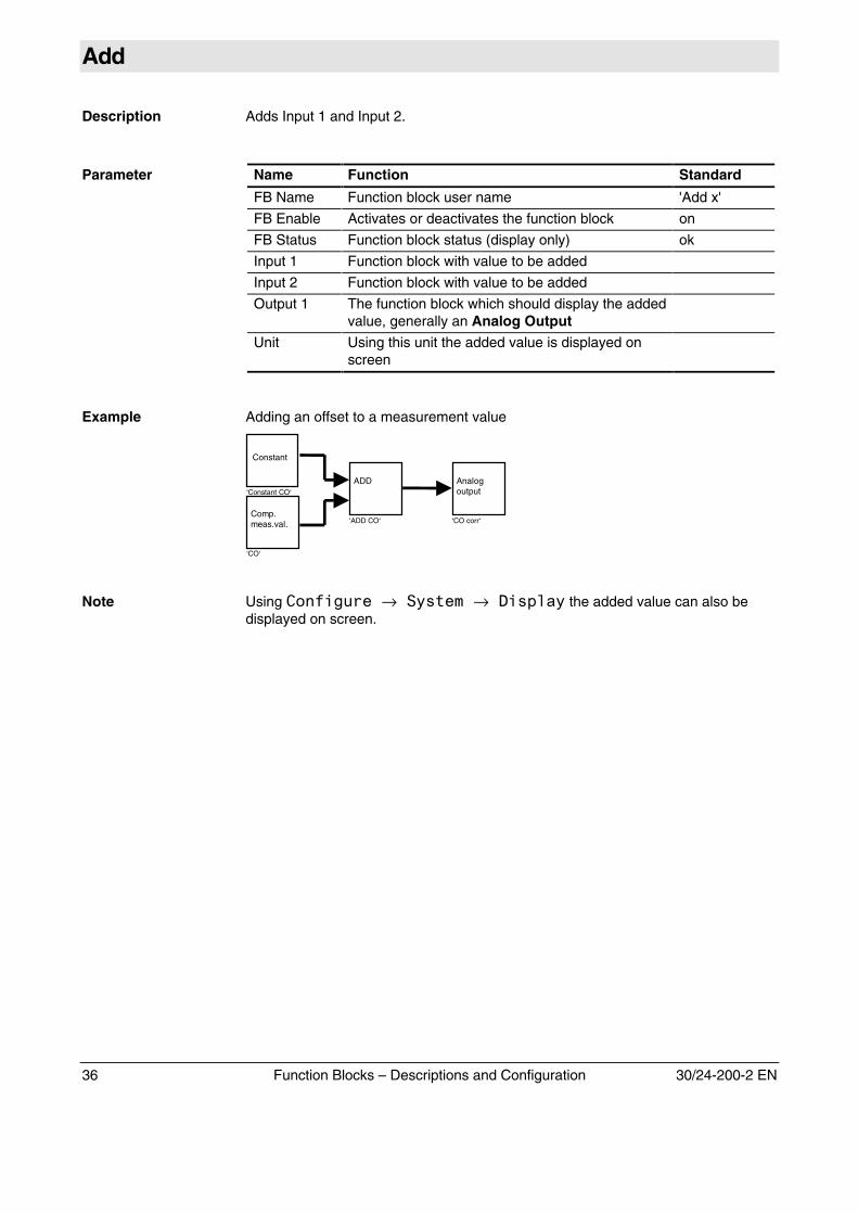
Description Adds Input 1 and Input 2.
Parameter Name Function Standard
FB Name Function block user name 'Add x'
FB Enable Activates or deactivates the function block on
FB Status Function block status (display only) ok
Input 1 Function block with value to be added
Input 2 Function block with value to be added
Output 1 The function block which should display the addedvalue, generally an Analog Output
Unit Using this unit the added value is displayed onscreen
Example Adding an offset to a measurement value
Constant
ADD
‘ADD CO‘Comp.meas.val.
‘CO‘
Analogoutput
‘CO corr‘
‘Constant CO‘
Note Using -��*�.�� →���� �→������� the added value can also bedisplayed on screen.
30/24-200-2 EN Function Blocks – Descriptions and Configuration 37
Subtract
Description Subtracts Input 2 from Input 1.
Parameter Name Function Standard
FB Name Function block user name 'Sub x'
FB Enable Activates or deactivates the function block on
FB Status Function block status (display only) ok
Input 1 'Input 2' is subtracted from this
Input 2
Output 1 The function block which should display thesubtracted value, generally an Analog output
Unit Using this unit the subtracted value is displayedon screen
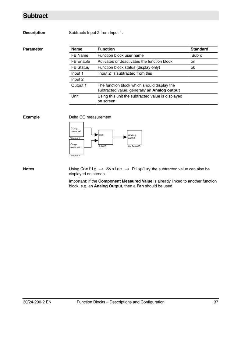
Example Delta CO measurement
Comp.meas.val.
SUB
‘SUB COComp.meas.val.
‘CO value 2‘
Analogoutput
I Out Delta CO
‘CO value 1‘
Notes Using -��*�.→���� �→������� the subtracted value can also bedisplayed on screen.
Important: If the Component Measured Value is already linked to another functionblock, e.g. an Analog Output, then a Fan should be used.
38 Function Blocks – Descriptions and Configuration 30/24-200-2 EN
Multiply
Description Multiplies Input 1 by Input 2.
Parameter Name Function Standard
FB Name Function block user name 'Mul x'
FB Enable Activates or deactivates the function block on
FB Status Function block status (display only) ok
Input 1 Function block to be multiplied by 'Input 2'
Input 2 Function block to be multiplied by 'Input 1'
Output 1 The function block which should display themultiplied value, generally an Analog output
Unit Using this unit the multiplied value is displayed onscreen
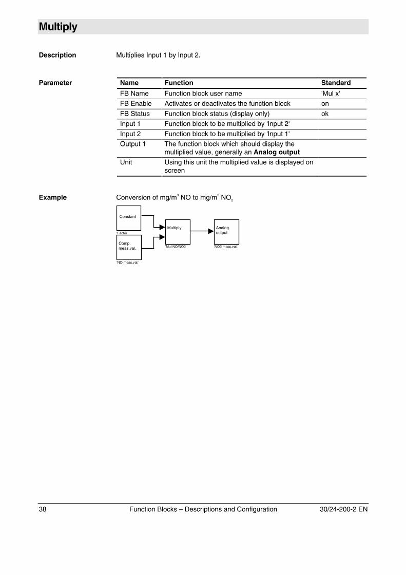
Example Conversion of mg/m3 NO to mg/m3 NO2
Constant
Multiply
‘Mul NO/NO2‘Comp.meas.val.
‘NO meas.val.‘
Analogoutput
‘NO2 meas.val.‘
‘Factor
30/24-200-2 EN Function Blocks – Descriptions and Configuration 39
Divide
Description Divides Input 1 by Input 2.
Parameter Name Function Standard
FB Name Function block user name 'Div x'
FB Enable Activates or deactivates the function block on
FB Status Function block status (display only) ok
Input 1 Function block to be divided by Input 2
Input 2 Dividend
Output 1 The function block which should display thedivided value, generally an Analog output
Unit Using this unit the divided value is displayed onscreen
Example
40 Function Blocks – Descriptions and Configuration 30/24-200-2 EN
Or
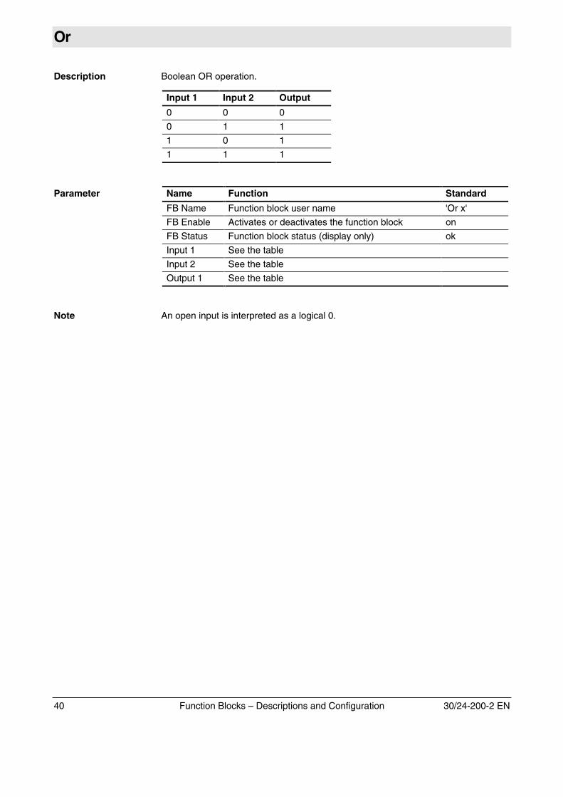
Description Boolean OR operation.
Input 1 Input 2 Output
0 0 0
0 1 1
1 0 1
1 1 1
Parameter Name Function Standard
FB Name Function block user name 'Or x'
FB Enable Activates or deactivates the function block on
FB Status Function block status (display only) ok
Input 1 See the table
Input 2 See the table
Output 1 See the table
Note An open input is interpreted as a logical 0.
30/24-200-2 EN Function Blocks – Descriptions and Configuration 41
And
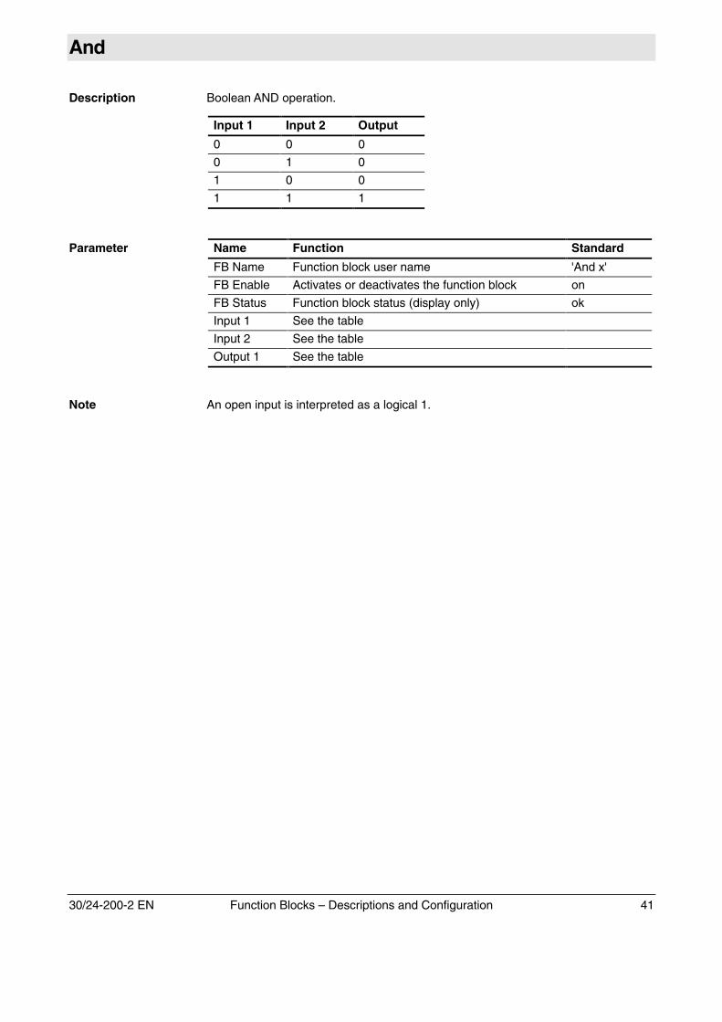
Description Boolean AND operation.
Input 1 Input 2 Output
0 0 0
0 1 0
1 0 0
1 1 1
Parameter Name Function Standard
FB Name Function block user name 'And x'
FB Enable Activates or deactivates the function block on
FB Status Function block status (display only) ok
Input 1 See the table
Input 2 See the table
Output 1 See the table
Note An open input is interpreted as a logical 1.
42 Function Blocks – Descriptions and Configuration 30/24-200-2 EN
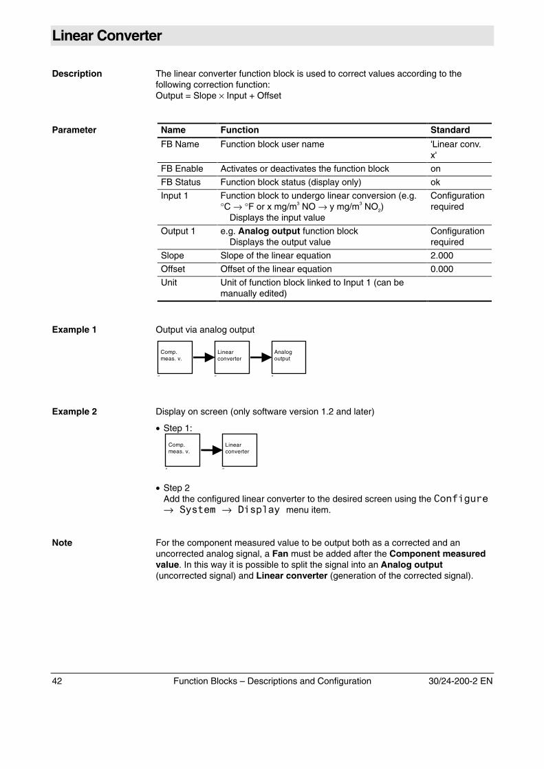
Linear Converter
Description The linear converter function block is used to correct values according to thefollowing correction function:Output = Slope × Input + Offset
Parameter Name Function Standard
FB Name Function block user name 'Linear conv.x'
FB Enable Activates or deactivates the function block on
FB Status Function block status (display only) ok
Input 1 Function block to undergo linear conversion (e.g.°C → °F or x mg/m3 NO → y mg/m3 NO2)
Displays the input value
Configurationrequired
Output 1 e.g. Analog output function blockDisplays the output value
Configurationrequired
Slope Slope of the linear equation 2.000
Offset Offset of the linear equation 0.000
Unit Unit of function block linked to Input 1 (can bemanually edited)
Example 1 Output via analog output
Linearconverter
‘’
Comp.meas. v.
‘’
Analogoutput
‘’
Example 2 Display on screen (only software version 1.2 and later)
• Step 1:
Linearconverter
‘’
Comp.meas. v.
‘’
• Step 2Add the configured linear converter to the desired screen using the -��*�.�� →���� �→�������menu item.
Note For the component measured value to be output both as a corrected and anuncorrected analog signal, a Fan must be added after the Component measuredvalue. In this way it is possible to split the signal into an Analog output(uncorrected signal) and Linear converter (generation of the corrected signal).
30/24-200-2 EN Function Blocks – Descriptions and Configuration 43
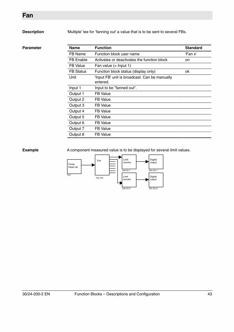
Fan
Description ‘Multiple’ tee for ‘fanning out’ a value that is to be sent to several FBs.
Parameter Name Function Standard
FB Name Function block user name 'Fan x'
FB Enable Activates or deactivates the function block on
FB Value Fan value (= Input 1)
FB Status Function block status (display only) ok
Unit 'Input FB' unit is broadcast. Can be manuallyentered.
Input 1 Input to be "fanned out".
Output 1 FB Value
Output 2 FB Value
Output 3 FB Value
Output 4 FB Value
Output 5 FB Value
Output 6 FB Value
Output 7 FB Value
Output 8 FB Value
Example A component measured value is to be displayed for several limit values.
Fan
‘Fan CO’
Limitmonitor
‘LM CO 1’
Comp.meas.val.
‘CO’
‘LM CO 2’
Limitmonitor
Digitaloutput
‘DO CO 1’
‘DO CO 2’
Digitaloutput
44 Function Blocks – Descriptions and Configuration 30/24-200-2 EN
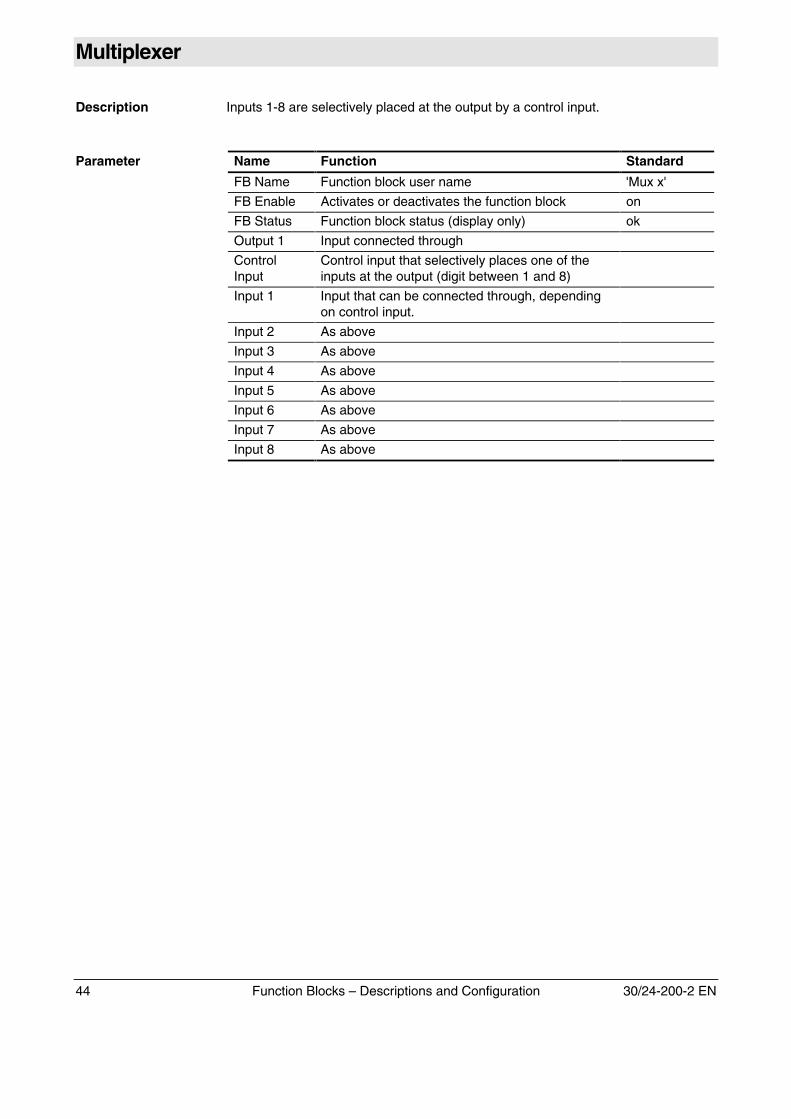
Multiplexer
Description Inputs 1-8 are selectively placed at the output by a control input.
Parameter Name Function Standard
FB Name Function block user name 'Mux x'
FB Enable Activates or deactivates the function block on
FB Status Function block status (display only) ok
Output 1 Input connected through
ControlInput
Control input that selectively places one of theinputs at the output (digit between 1 and 8)
Input 1 Input that can be connected through, dependingon control input.
Input 2 As above
Input 3 As above
Input 4 As above
Input 5 As above
Input 6 As above
Input 7 As above
Input 8 As above
Example

30/24-200-2 EN Function Blocks – Descriptions and Configuration 45
Demultiplexer
Description The input is placed at one of the outputs (1-8) by a control input.
Parameter Name Function Standard
FB Name Function block user name 'Demux x'
FB Enable Activates or deactivates the function block on
FB Status Function block status (display only) ok
Input 1 Input that can be connected through to one of theoutputs, depending on control input.
ControlInput
Control input that selectively places the input atone of the outputs (digit between 1 and 8)
Output 1 Input connected through or 0
Output 2 As above
Output 3 As above
Output 4 As above
Output 5 As above
Output 6 As above
Output 7 As above
Output 8 As above
Example
46 Function Blocks – Descriptions and Configuration 30/24-200-2 EN
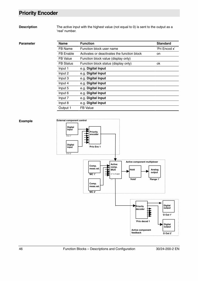
Priority Encoder
Description The active input with the highest value (not equal to 0) is sent to the output as a‘real’ number.
Parameter Name Function Standard
FB Name Function block user name ‘Pri Encod x’
FB Enable Activates or deactivates the function block on
FB Value Function block value (display only)
FB Status Function block status (display only) ok
Input 1 e.g. Digital InputInput 2 e.g. Digital InputInput 3 e.g. Digital InputInput 4 e.g. Digital InputInput 5 e.g. Digital InputInput 6 e.g. Digital InputInput 7 e.g. Digital InputInput 8 e.g. Digital InputOutput 1 FB Value
Example External component control
Comp.meas.val.
‘MC 1’
Analogoutput
‘Range 1’
Hold
‘Hold’
Activecomp.MUX
in % of span
‘’
Comp.meas.val.
‘MC 2’
‘Prio Enc 1
Priorityencoder
Digitalinput
‘D In 1’
Digitalinput
‘D In 2’
‘Prio decod 1
Prioritydecoder
Digitaloutput
‘D Out 2’
Digitaloutput
‘D Out 1’
Active component multiplexer
Active componentfeedback
30/24-200-2 EN Function Blocks – Descriptions and Configuration 47
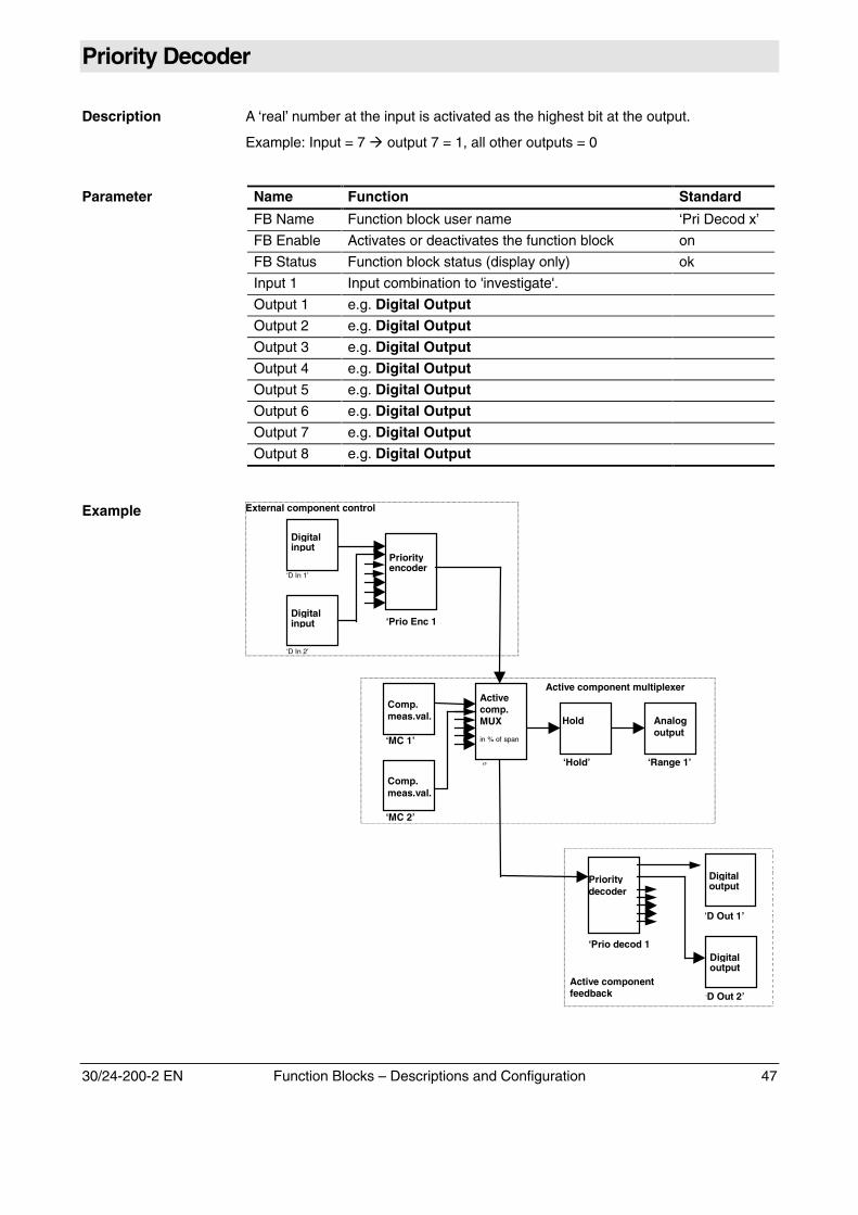
Priority Decoder
Description A ‘real’ number at the input is activated as the highest bit at the output.
Example: Input = 7 � output 7 = 1, all other outputs = 0
Parameter Name Function Standard
FB Name Function block user name ‘Pri Decod x’
FB Enable Activates or deactivates the function block on
FB Status Function block status (display only) ok
Input 1 Input combination to 'investigate'.
Output 1 e.g. Digital OutputOutput 2 e.g. Digital OutputOutput 3 e.g. Digital OutputOutput 4 e.g. Digital OutputOutput 5 e.g. Digital OutputOutput 6 e.g. Digital OutputOutput 7 e.g. Digital OutputOutput 8 e.g. Digital Output
Example External component control
Comp.meas.val.
‘MC 1’
Analogoutput
‘Range 1’
Hold
‘Hold’
Activecomp.MUX
in % of span
‘’
Comp.meas.val.
‘MC 2’
‘Prio Enc 1
Priorityencoder
Digitalinput
‘D In 1’
Digitalinput
‘D In 2’
‘Prio decod 1
Prioritydecoder
Digitaloutput
‘D Out 2’
Digitaloutput
‘D Out 1’
Active component multiplexer
Active componentfeedback
48 Function Blocks – Descriptions and Configuration 30/24-200-2 EN
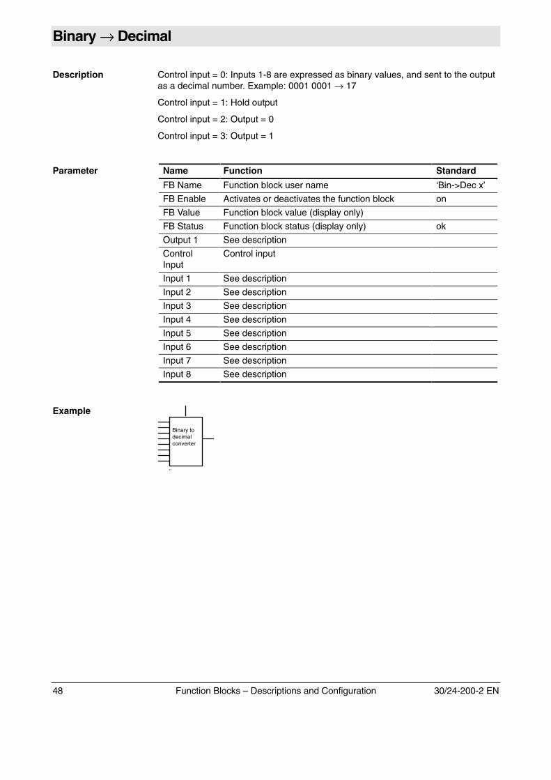
Binary → Decimal
Description Control input = 0: Inputs 1-8 are expressed as binary values, and sent to the outputas a decimal number. Example: 0001 0001 → 17
Control input = 1: Hold output
Control input = 2: Output = 0
Control input = 3: Output = 1
Parameter Name Function Standard
FB Name Function block user name ‘Bin->Dec x’
FB Enable Activates or deactivates the function block on
FB Value Function block value (display only)
FB Status Function block status (display only) ok
Output 1 See description
ControlInput
Control input
Input 1 See description
Input 2 See description
Input 3 See description
Input 4 See description
Input 5 See description
Input 6 See description
Input 7 See description
Input 8 See description
Example
Binary todecimalconverter
‘’
30/24-200-2 EN Function Blocks – Descriptions and Configuration 49
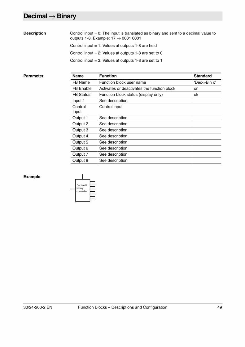
Decimal → Binary
Description Control input = 0: The input is translated as binary and sent to a decimal value tooutputs 1-8. Example: 17 → 0001 0001
Control input = 1: Values at outputs 1-8 are held
Control input = 2: Values at outputs 1-8 are set to 0
Control input = 3: Values at outputs 1-8 are set to 1
Parameter Name Function Standard
FB Name Function block user name ‘Dec->Bin x’
FB Enable Activates or deactivates the function block on
FB Status Function block status (display only) ok
Input 1 See description
ControlInput
Control input
Output 1 See description
Output 2 See description
Output 3 See description
Output 4 See description
Output 5 See description
Output 6 See description
Output 7 See description
Output 8 See description
Example
Decimal tobinaryconverter
‘’
50 Function Blocks – Descriptions and Configuration 30/24-200-2 EN
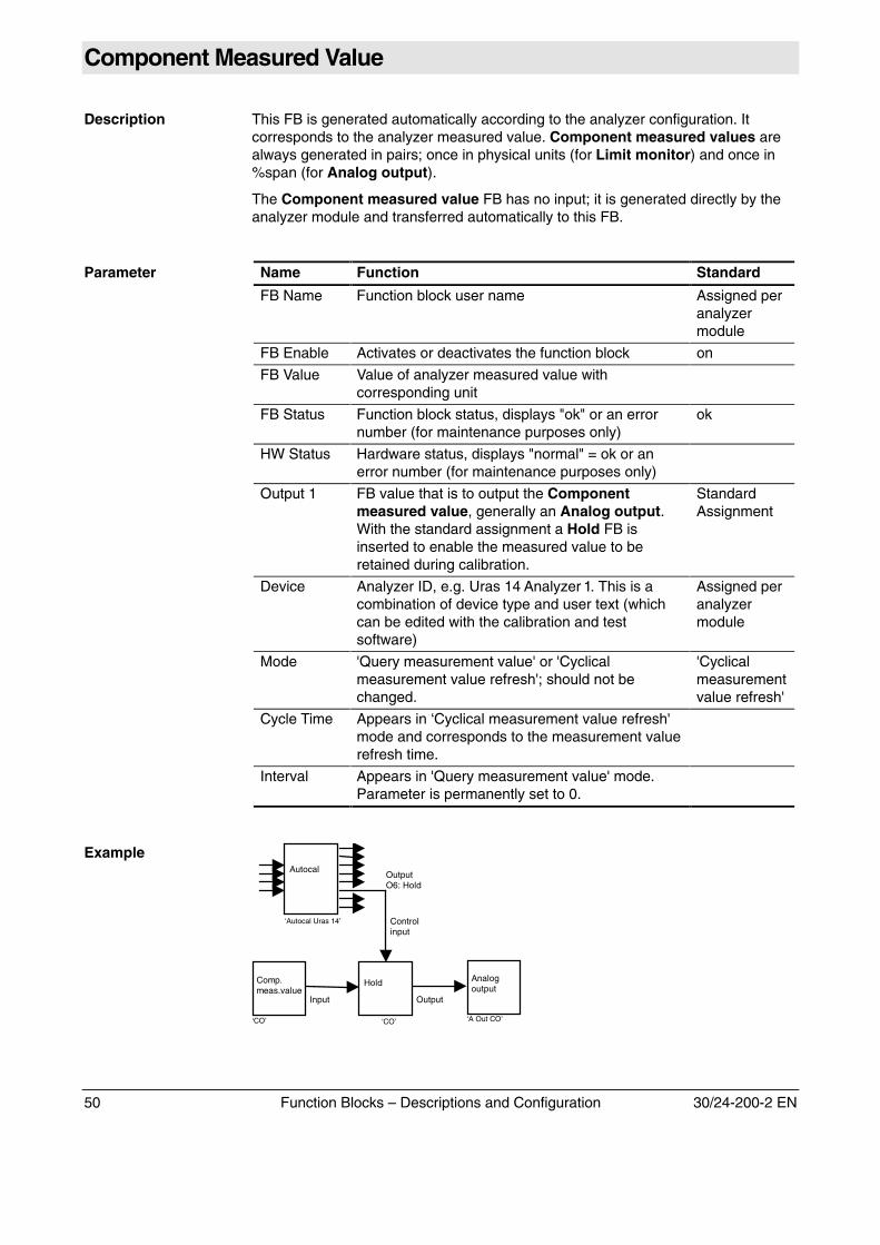
Component Measured Value
Description This FB is generated automatically according to the analyzer configuration. Itcorresponds to the analyzer measured value. Component measured values arealways generated in pairs; once in physical units (for Limit monitor) and once in%span (for Analog output).
The Component measured value FB has no input; it is generated directly by theanalyzer module and transferred automatically to this FB.
Parameter Name Function Standard
FB Name Function block user name Assigned peranalyzermodule
FB Enable Activates or deactivates the function block on
FB Value Value of analyzer measured value withcorresponding unit
FB Status Function block status, displays "ok" or an errornumber (for maintenance purposes only)
ok
HW Status Hardware status, displays "normal" = ok or anerror number (for maintenance purposes only)
Output 1 FB value that is to output the Componentmeasured value, generally an Analog output.With the standard assignment a Hold FB isinserted to enable the measured value to beretained during calibration.
StandardAssignment
Device Analyzer ID, e.g. Uras 14 Analyzer 1. This is acombination of device type and user text (whichcan be edited with the calibration and testsoftware)
Assigned peranalyzermodule
Mode 'Query measurement value' or 'Cyclicalmeasurement value refresh'; should not bechanged.
'Cyclicalmeasurementvalue refresh'
Cycle Time Appears in ‘Cyclical measurement value refresh'mode and corresponds to the measurement valuerefresh time.
Interval Appears in 'Query measurement value' mode.Parameter is permanently set to 0.
Example
Analogoutput
‘A Out CO’
Hold
‘CO’
Comp.meas.value
‘CO’
Input Output
Controlinput
Autocal
‘Autocal Uras 14’
OutputO6: Hold
30/24-200-2 EN Function Blocks – Descriptions and Configuration 51
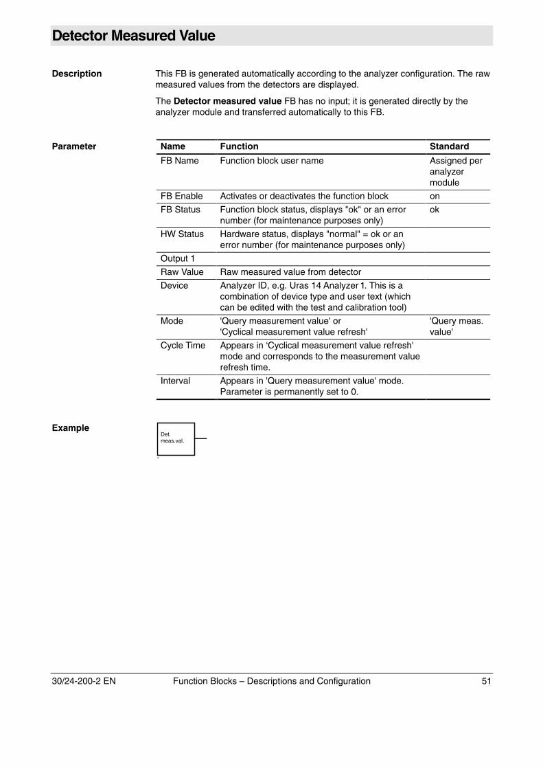
Detector Measured Value
Description This FB is generated automatically according to the analyzer configuration. The rawmeasured values from the detectors are displayed.
The Detector measured value FB has no input; it is generated directly by theanalyzer module and transferred automatically to this FB.
Parameter Name Function Standard
FB Name Function block user name Assigned peranalyzermodule
FB Enable Activates or deactivates the function block on
FB Status Function block status, displays "ok" or an errornumber (for maintenance purposes only)
ok
HW Status Hardware status, displays "normal" = ok or anerror number (for maintenance purposes only)
Output 1
Raw Value Raw measured value from detector
Device Analyzer ID, e.g. Uras 14 Analyzer 1. This is acombination of device type and user text (whichcan be edited with the test and calibration tool)
Mode 'Query measurement value' or'Cyclical measurement value refresh'
'Query meas.value'
Cycle Time Appears in ‘Cyclical measurement value refresh'mode and corresponds to the measurement valuerefresh time.
Interval Appears in 'Query measurement value' mode.Parameter is permanently set to 0.
ExampleDet.meas.val.
‘’
52 Function Blocks – Descriptions and Configuration 30/24-200-2 EN
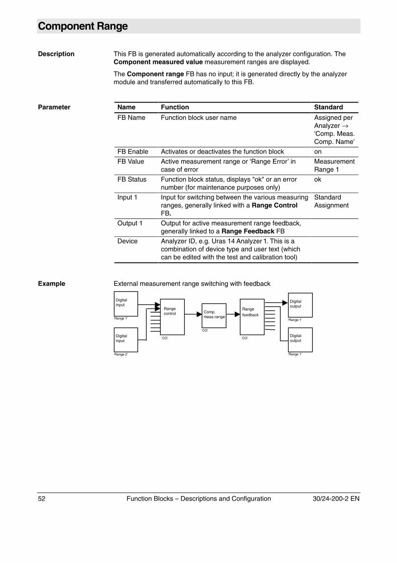
Component Range
Description This FB is generated automatically according to the analyzer configuration. TheComponent measured value measurement ranges are displayed.
The Component range FB has no input; it is generated directly by the analyzermodule and transferred automatically to this FB.
Parameter Name Function Standard
FB Name Function block user name Assigned perAnalyzer →'Comp. Meas.Comp. Name'
FB Enable Activates or deactivates the function block on
FB Value Active measurement range or ‘Range Error’ incase of error
MeasurementRange 1
FB Status Function block status, displays "ok" or an errornumber (for maintenance purposes only)
ok
Input 1 Input for switching between the various measuringranges, generally linked with a Range ControlFB.
StandardAssignment
Output 1 Output for active measurement range feedback,generally linked to a Range Feedback FB
Device Analyzer ID, e.g. Uras 14 Analyzer 1. This is acombination of device type and user text (whichcan be edited with the test and calibration tool)
Example External measurement range switching with feedback
Comp.meas.range
‘CO’
Digitalinput
‘Range 1’
Digitalinput
‘Range 2’
Rangecontrol
‘CO’
Rangefeedback
‘CO’Digitaloutput
‘Range 1’
Digitaloutput
‘Range 1’
30/24-200-2 EN Function Blocks – Descriptions and Configuration 53
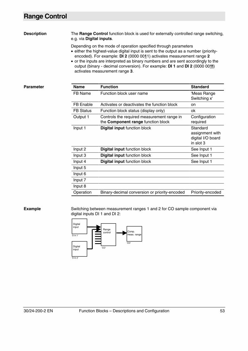
Range Control
Description The Range Control function block is used for externally controlled range switching,e.g. via Digital inputs.
Depending on the mode of operation specified through parameters• either the highest-value digital input is sent to the output as a number (priority-
encoded). For example: DI 2 (0000 0011) activates measurement range 2 • or the inputs are interpreted as binary numbers and are sent accordingly to the
output (binary - decimal conversion). For example: DI 1 and DI 2 (0000 0011) activates measurement range 3.
Parameter Name Function Standard
FB Name Function block user name 'Meas RangeSwitching x'
FB Enable Activates or deactivates the function block on
FB Status Function block status (display only) ok
Output 1 Controls the required measurement range inthe Component range function block
Configurationrequired
Input 1 Digital input function block Standardassignment withdigital I/O boardin slot 3
Input 2 Digital input function block See Input 1
Input 3 Digital input function block See Input 1
Input 4 Digital input function block See Input 1
Input 5
Input 6
Input 7
Input 8
Operation Binary-decimal conversion or priority-encoded Priority-encoded
Example Switching between measurement ranges 1 and 2 for CO sample component viadigital inputs DI 1 and DI 2:
Rangecontrol
‘CO’
Comp.meas. range
‘CO’
Digitalinput
‘D In 1’
Digitalinput
‘D In 2’
54 Function Blocks – Descriptions and Configuration 30/24-200-2 EN
Range Feedback
Description The Range feedback function block is used to report the measurement range inuse, e.g. via Digital outputs.
Depending on the mode of operation specified through parameters• either the active measurement range is sent to the output as a number (priority-
encoded). For example: Measurement Range 2 activates Digital output 2 (0000 0010)
• or the active measurement range is interpreted as a binary number and is sent tothe output (binary - decimal conversion). For example: Measurement range 3 activates DI 1 and DI 2 (0000 0011).
Parameter Name Function Standard
FB Name Function block user name 'RangeFeedback x'
FB Enable Activates or deactivates the function block on
FB Value Function block value (display only) 0
FB Status Function block status (display only) ok
Input 1 Transfer of active measurement range fromComponent range function block
Configurationrequired
Output 1 Digital output function block Standardassignment withdigital I/O boardin slot 3
Output 2 Digital output function block See above
Output 3 Digital output function block See above
Output 4 Digital output function block See above
Output 5
Output 6
Output 7
Output 8
Operation Decimal-binary conversion or priority-decoded Priority-decoded
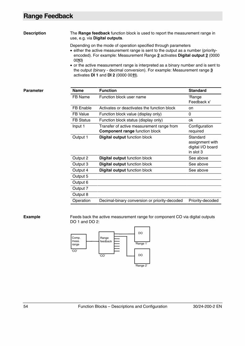
Example Feeds back the active measurement range for component CO via digital outputsDO 1 and DO 2:
Comp.meas.range
‘CO’
DO
‘Range 1’
DO
‘Range 2’
Rangefeedback
‘CO’
30/24-200-2 EN Function Blocks – Descriptions and Configuration 55
Active Component Multiplexer
Description The output of this FB always contains the value of the active component (whichmust be linked to the inputs in the form of FBs). This FB is only relevant toanalyzers capable of measuring several components with the same detector (e.g.Caldos 17).
Depending on the number of Analog outputs available, the Componentmeasured values are already linked with an Active Component MUX both as aphysical unit (e.g. ppm or Vol%) as well as % span in the standard configuration.Control of the active component occurs in the same way as control of measurementrange through the HMI in menu item -��*�.�� →-����� ��/�� ��*��→����� -����� ��. Additional control inputs and outputs can be used forexternal component switching or feedback (as for range switching or feedback).
The Component measured values linked with the inputs are sent to the output inaccordance with the control input (the output, in turn, can be linked to an Analogoutput FB via a Hold FB). The control input is interpreted as a ‘real’ number (=priority-encoded). The lowest-numbered inputs must be connected first (input 1 first,followed by input 2, etc.).
The component selected as active is displayed (as a ‘real’ number) via the ‘Feedb.’output. This output can be used to feedback the selected component.
Caution! In software version 1.1 no other FB should be used between the Comp. meas.value (phys. or %span) FB and the Active Component MUX FB.In software version 1.3.2 and later no FB Feedback should be used between theComp. meas. value (phys. or %span) FB and the Active Component MUX FB.
Parameter Name Function Standard
FB Name Active component name 'CompMux x'
FB Enable Activates or deactivates the function block on
FB Status Function block status (display only) ok
Output 1 Value of selected input
Input 1 Sample component � Comp. Value FB or empty
Input 2 Sample component � Comp. Value FB or empty
Input 3 Sample component � Comp. Value FB or empty
Input 4 Sample component � Comp. Value FB or empty
Input 5 Sample component � Comp. Value FB or empty
Input 6 Sample component � Comp. Value FB or empty
Input 7 Sample component � Comp. Value FB or empty
ControlInput
Optional: ‘Real’ number for selecting an input tobe sent to the output (e.g. for implementingexternal component selection)
Feedback Optional: Represents the component currentlyselected (can be used to feedback the activecomponent via DOs)
Unit Preset with the measurement component unit.Can be edited if no useful unit is available at theinputs.
Continued on next page
56 Function Blocks – Descriptions and Configuration 30/24-200-2 EN
Active Component Multiplexer, continued
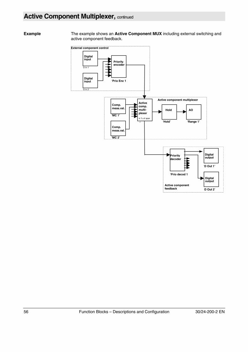
Example The example shows an Active Component MUX including external switching andactive component feedback.
External component control
Comp.meas.val.
‘MC 1’
AO
‘Range 1’
Hold
‘Hold’
Activecomp.multi-plexer
in % of span
‘’
Comp.meas.val.
‘MC 2’
‘Prio Enc 1
Priorityencoder
Digitalinput
‘D In 1’
Digitalinput
‘D In 2’
‘Prio decod 1
Prioritydecoder
Digitaloutput
‘D Out 2’
Digitaloutput
‘D Out 1’
Active component multiplexer
Active componentfeedback
30/24-200-2 EN Function Blocks – Descriptions and Configuration 57
Calibration Cell
Description This FB controls a Uras 14 analyzer module calibration cell.
Parameter Name Function Standard
FB Name Function block user name ‘Cal. Cell n‘
FB Enable Activates or deactivates the function block on
FB Value Shows the position of the calibration cell:out = ‘out’ position, in = ‘in’ position
FB Status Function block status, displays "ok" or an errornumber (for maintenance purposes only)
ok
HW Status Hardware status, displays "normal" = ok or anerror number (for maintenance purposes only)
Normal
Input 1 Input for controlling the calibration cell StandardAssignment
Cal. Cell No. Sequential number of installed calibration cells ‘n‘
Example See Autocalibration
58 Function Blocks – Descriptions and Configuration 30/24-200-2 EN
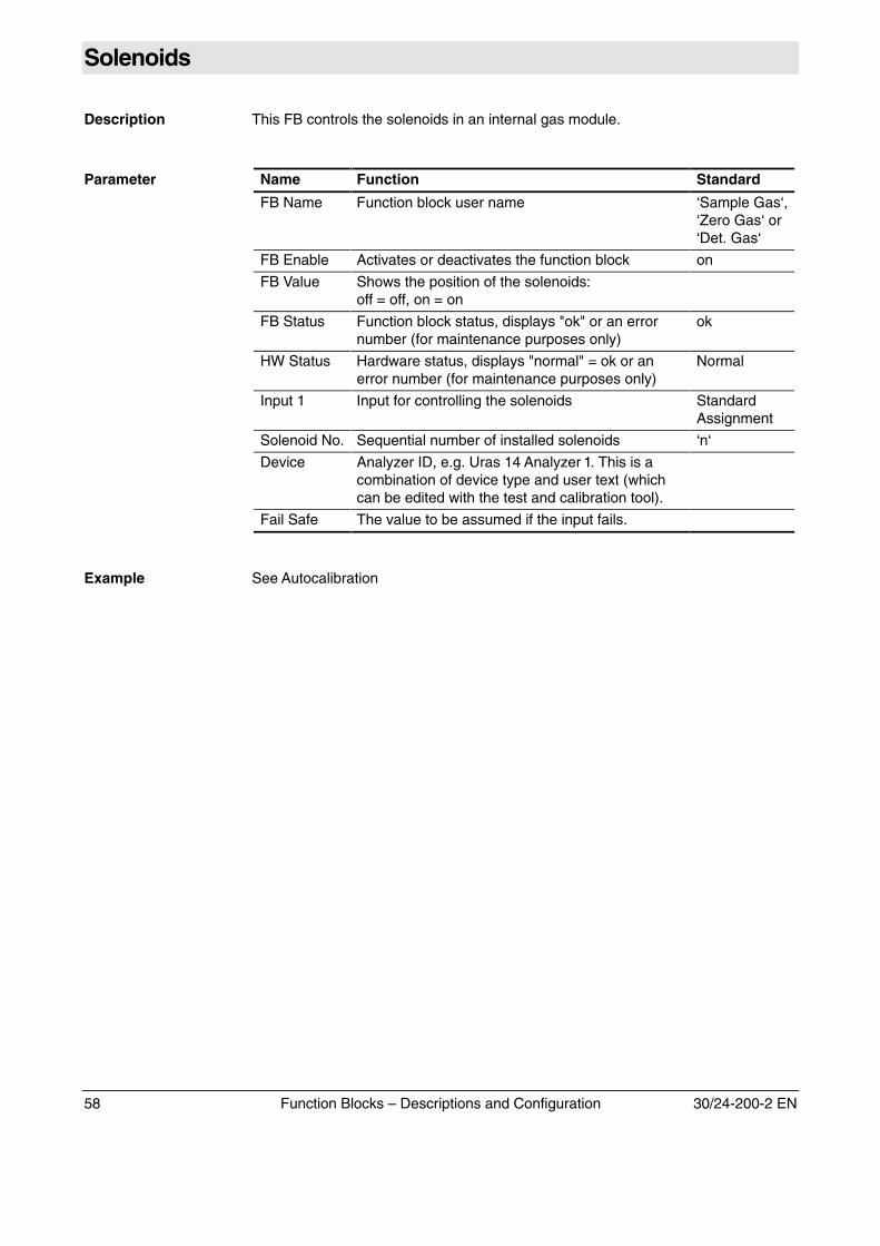
Solenoids
Description This FB controls the solenoids in an internal gas module.
Parameter Name Function Standard
FB Name Function block user name ‘Sample Gas‘,‘Zero Gas‘ or‘Det. Gas‘
FB Enable Activates or deactivates the function block on
FB Value Shows the position of the solenoids:off = off, on = on
FB Status Function block status, displays "ok" or an errornumber (for maintenance purposes only)
ok
HW Status Hardware status, displays "normal" = ok or anerror number (for maintenance purposes only)
Normal
Input 1 Input for controlling the solenoids StandardAssignment
Solenoid No. Sequential number of installed solenoids ‘n‘
Device Analyzer ID, e.g. Uras 14 Analyzer 1. This is acombination of device type and user text (whichcan be edited with the test and calibration tool).
Fail Safe The value to be assumed if the input fails.
Example See Autocalibration
30/24-200-2 EN Function Blocks – Descriptions and Configuration 59
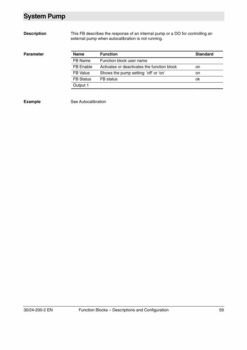
System Pump
Description This FB describes the response of an internal pump or a DO for controlling anexternal pump when autocalibration is not running.
Parameter Name Function Standard
FB Name Function block user name
FB Enable Activates or deactivates the function block on
FB Value Shows the pump setting: 'off' or 'on' on
FB Status FB status ok
Output 1
Example See Autocalibration
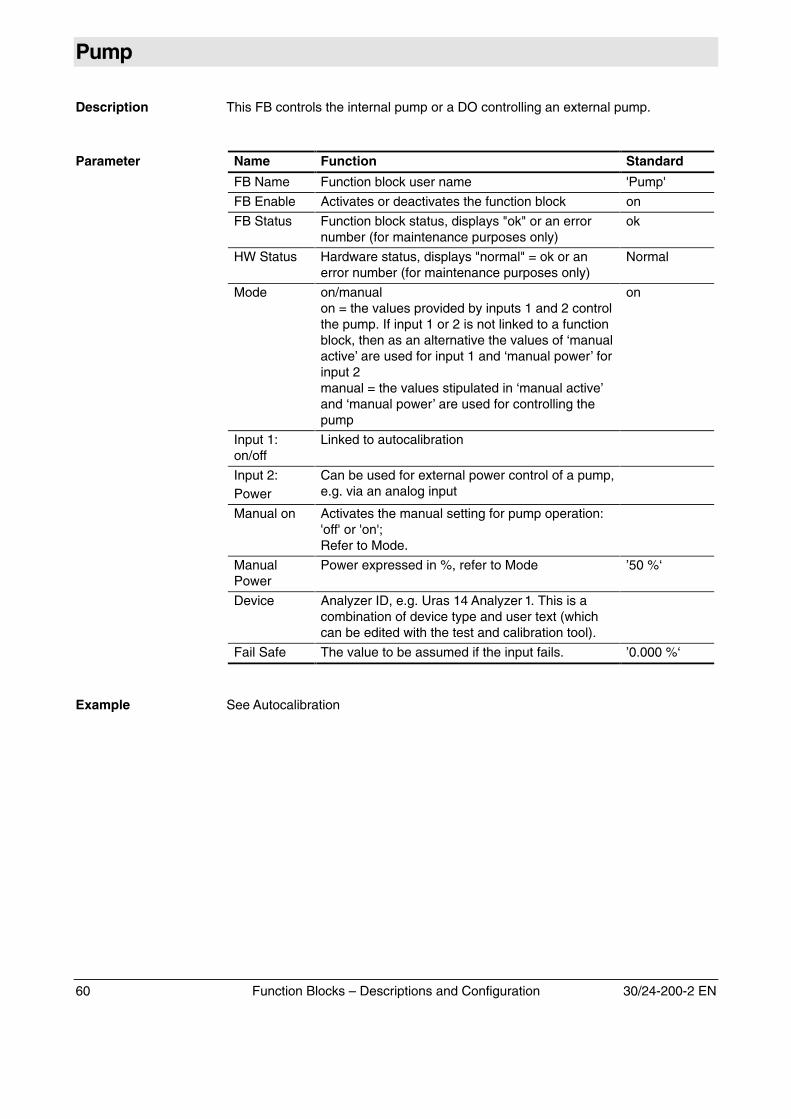
60 Function Blocks – Descriptions and Configuration 30/24-200-2 EN
Pump
Description This FB controls the internal pump or a DO controlling an external pump.
Parameter Name Function Standard
FB Name Function block user name 'Pump'
FB Enable Activates or deactivates the function block on
FB Status Function block status, displays "ok" or an errornumber (for maintenance purposes only)
ok
HW Status Hardware status, displays "normal" = ok or anerror number (for maintenance purposes only)
Normal
Mode on/manualon = the values provided by inputs 1 and 2 controlthe pump. If input 1 or 2 is not linked to a functionblock, then as an alternative the values of ‘manualactive’ are used for input 1 and ‘manual power’ forinput 2manual = the values stipulated in ‘manual active’and ‘manual power’ are used for controlling thepump
on
Input 1:on/off
Linked to autocalibration
Input 2:Power
Can be used for external power control of a pump,e.g. via an analog input
Manual on Activates the manual setting for pump operation:'off' or 'on';Refer to Mode.
ManualPower
Power expressed in %, refer to Mode ’50 %‘
Device Analyzer ID, e.g. Uras 14 Analyzer 1. This is acombination of device type and user text (whichcan be edited with the test and calibration tool).
Fail Safe The value to be assumed if the input fails. ’0.000 %‘
Example See Autocalibration
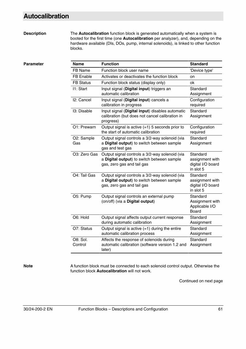
30/24-200-2 EN Function Blocks – Descriptions and Configuration 61
Autocalibration
Description The Autocalibration function block is generated automatically when a system isbooted for the first time (one Autocalibration per analyzer), and, depending on thehardware available (DIs, DOs, pump, internal solenoids), is linked to other functionblocks.
Parameter Name Function Standard
FB Name Function block user name 'Device type'
FB Enable Activates or deactivates the function block on
FB Status Function block status (display only) ok
I1: Start Input signal (Digital input) triggers anautomatic calibration
StandardAssignment
I2: Cancel Input signal (Digital input) cancels acalibration in progress
Configurationrequired
I3: Disable Input signal (Digital input) disables automaticcalibration (but does not cancel calibration inprogress)
StandardAssignment
O1: Prewarn Output signal is active (=1) 5 seconds prior tothe start of automatic calibration
Configurationrequired
O2: SampleGas
Output signal controls a 3/2-way solenoid (viaa Digital output) to switch between samplegas and test gas
StandardAssignment
O3: Zero Gas Output signal controls a 3/2-way solenoid (viaa Digital output) to switch between samplegas, zero gas and tail gas
Standardassignment withdigital I/O boardin slot 5
O4: Tail Gas Output signal controls a 3/2-way solenoid (viaa Digital output) to switch between samplegas, zero gas and tail gas
Standardassignment withdigital I/O boardin slot 5
O5: Pump Output signal controls an external pump(on/off) (via a Digital output)
StandardAssignment withApplicable I/OBoard
O6: Hold Output signal affects output current responseduring automatic calibration
StandardAssignment
O7: Status Output signal is active (=1) during the entireautomatic calibration process
StandardAssignment
O8: Sol.Control
Affects the response of solenoids duringautomatic calibration (software version 1.2 andlater)
StandardAssignment
Note A function block must be connected to each solenoid control output. Otherwise thefunction block Autocalibration will not work.
Continued on next page
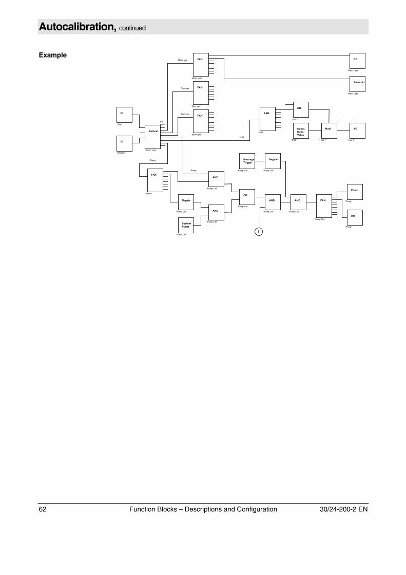
62 Function Blocks – Descriptions and Configuration 30/24-200-2 EN
Autocalibration, continued
ExampleDO
‘Meas. gas‘
Solenoid
‘Meas. gas‘
FAN
‘Meas. gas’
FAN
‘Zero gas’
FAN
‘Span gas’
FAN
‘Status’
Autocal
‘Autoc Uras’
DI
‘Start‘
DI
‘Disable‘
FAN
‘Hold’
OR
‘I out 1‘
Hold
‘I out 1‘
AO
‘I out 1‘
Comp.Meas.Value
‘CO2‘
Meas gas
Zero gas
Span gas
Hold
Status
AND
‘Pump Ctrl‘
OR
‘Pump Ctrl‘
Negate
‘Pump Ctrl.‘ AND
‘Pump Ctrl‘SystemPump
‘Pump Ctrl.’
AND
‘Pump Ctrl‘
AND
‘Pump Ctrl‘
FAN
‘Pump Ctrl.’
Pump
‘Pump‘
DO
‘Pump‘
Negate
‘Pump Ctrl‘Pump
MessageTrigger
‘Pump Ctrl.‘
1
Pre-warn.
30/24-200-2 EN Function Blocks – Descriptions and Configuration 63
Externally Controlled Calibration
Description The Externally controlled calibration FB can be used, for example, to perform acalibration via Digital inputs. Gas activation, calibration cell movement andsubsequent waiting for a stable measured value is then performed externally, e.g.via a PLC.
With the Uras 14, when the calibration cell is inserted the calibration cell gasconcentration values stored in the device are used for correcting the calibration.Insertion of the calibration cell should also be controlled via a Digital input.
Parameter Name Function Standard
FB Name Function block user name ‘xx DeviceType' with ZPfor Zero andEP for End
FB Enable Activates or deactivates the function block on
FB Status Function block status (display only) ok
Input 1 Input signal (Digital input) triggers externalcalibration
Displays the input value
StandardAssignment
CalibrationData
Access to the parameters for calibrationmethod, calculation method, test gasconcentration and calibration components (seebelow)
CalibrationMethod
Standard gas, substitute gas or commoncalibration
Commoncalibration(substitute gascalibration, ifavailable)
CalculationMethod
Calculation as offset calibration, amplificationcalibration, or offset and amplificationcalibration
Offset
Test GasConcentration
Changing the test gas concentrations for allmeasurement components
MeasurementRange Limits
Componentsfor Calibration
When the FB is created automatically (after ananalyzer module has been added), allmeasurement components are chosen forexternally controlled calibration.
When the calibration method is switched tocommon calibration, the requiredmeasurement components must be selectedmanually.
All samplecomponents
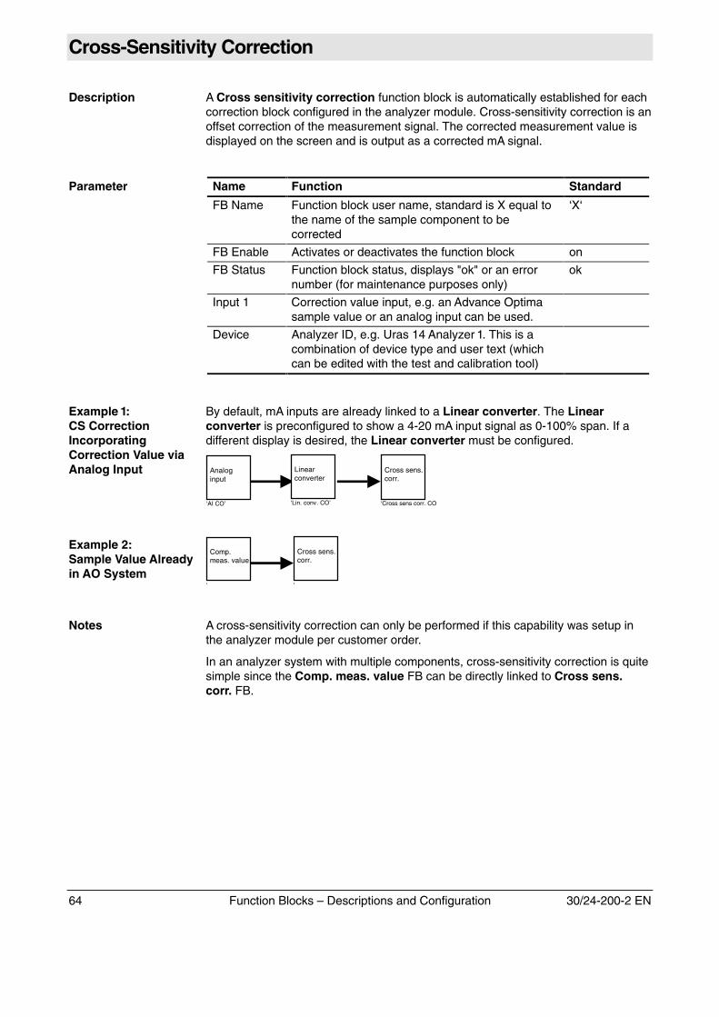
64 Function Blocks – Descriptions and Configuration 30/24-200-2 EN
Cross-Sensitivity Correction
Description A Cross sensitivity correction function block is automatically established for eachcorrection block configured in the analyzer module. Cross-sensitivity correction is anoffset correction of the measurement signal. The corrected measurement value isdisplayed on the screen and is output as a corrected mA signal.
Parameter Name Function Standard
FB Name Function block user name, standard is X equal tothe name of the sample component to becorrected
‘X‘
FB Enable Activates or deactivates the function block on
FB Status Function block status, displays "ok" or an errornumber (for maintenance purposes only)
ok
Input 1 Correction value input, e.g. an Advance Optimasample value or an analog input can be used.
Device Analyzer ID, e.g. Uras 14 Analyzer 1. This is acombination of device type and user text (whichcan be edited with the test and calibration tool)
Example 1:CS CorrectionIncorporatingCorrection Value viaAnalog Input
By default, mA inputs are already linked to a Linear converter. The Linearconverter is preconfigured to show a 4-20 mA input signal as 0-100% span. If adifferent display is desired, the Linear converter must be configured.
Analoginput
‘AI CO’
Linearconverter
‘Lin. conv. CO’
Cross sens.corr.
‘Cross sens corr. CO
Example 2:Sample Value Alreadyin AO System
Comp.meas. value
‘
Cross sens.corr.
‘
Notes A cross-sensitivity correction can only be performed if this capability was setup inthe analyzer module per customer order.
In an analyzer system with multiple components, cross-sensitivity correction is quitesimple since the Comp. meas. value FB can be directly linked to Cross sens.corr. FB.
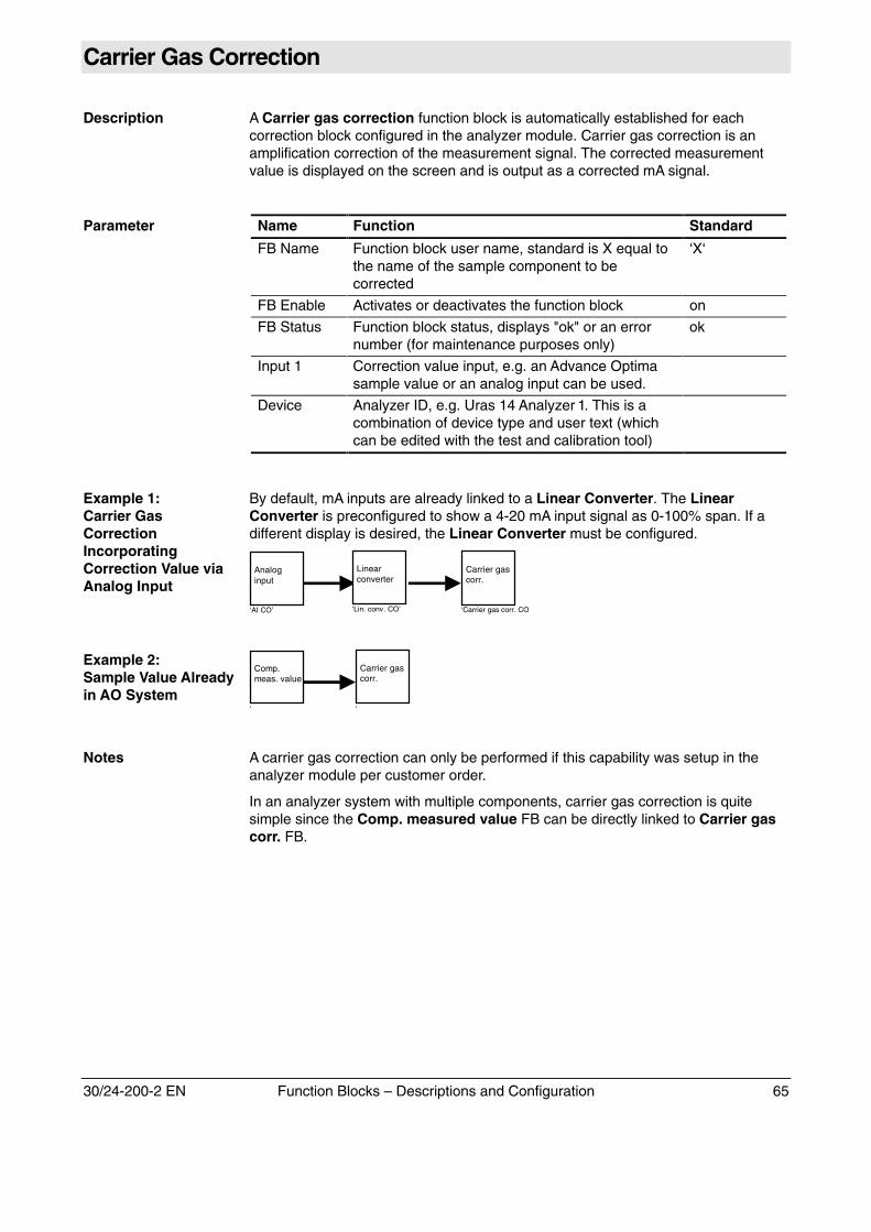
30/24-200-2 EN Function Blocks – Descriptions and Configuration 65
Carrier Gas Correction
Description A Carrier gas correction function block is automatically established for eachcorrection block configured in the analyzer module. Carrier gas correction is anamplification correction of the measurement signal. The corrected measurementvalue is displayed on the screen and is output as a corrected mA signal.
Parameter Name Function Standard
FB Name Function block user name, standard is X equal tothe name of the sample component to becorrected
‘X‘
FB Enable Activates or deactivates the function block on
FB Status Function block status, displays "ok" or an errornumber (for maintenance purposes only)
ok
Input 1 Correction value input, e.g. an Advance Optimasample value or an analog input can be used.
Device Analyzer ID, e.g. Uras 14 Analyzer 1. This is acombination of device type and user text (whichcan be edited with the test and calibration tool)
Example 1:Carrier GasCorrectionIncorporatingCorrection Value viaAnalog Input
By default, mA inputs are already linked to a Linear Converter. The LinearConverter is preconfigured to show a 4-20 mA input signal as 0-100% span. If adifferent display is desired, the Linear Converter must be configured.
Analoginput
‘AI CO’
Linearconverter
‘Lin. conv. CO’
Carrier gascorr.
‘Carrier gas corr. CO
Example 2:Sample Value Alreadyin AO System
Comp.meas. value
‘
Carrier gascorr.
‘
Notes A carrier gas correction can only be performed if this capability was setup in theanalyzer module per customer order.
In an analyzer system with multiple components, carrier gas correction is quitesimple since the Comp. measured value FB can be directly linked to Carrier gascorr. FB.

Subject to technical changesPrinted in the Fed. Rep. of Germany
30/24-200-2 EN 03.00