Embed Size (px)
Citation preview
FUNCTIONALLY GRADED JOINTS BY
DIELECTRIC HEATING
LUIS FERNANDO SANFELICES ANDRÉS DISSERTAÇÃO DE MESTRADO APRESENTADA À FACULDADE DE ENGENHARIA DA UNIVERSIDADE DO PORTO EM ÁREA CIENTÍFICA PRODUÇÃO E ENGENHARIA AUTOMÓVEL
M 2014
Functionally graded joints by
dielectric heating
Submited by
Luis Fernando Sanfelices Andrés
Supervised by
Lucas Filipe Martins da Silva
Co-supervised by
Ricardo João Camilo Carbas
July 2014

i
Abstract
The most traditional methods of fastening such as bolts or rivets have been used for
decades. However, these cause stress concentrations and premature failure in materials,
while adhesive bonds spread the load more evenly over the surface, facilitating a lighter
and cheaper overall structure. That is the main reason why adhesively bonded joints are
increasingly used in aerospace and automotive industries.
The single lap joint (SLJ) with metallic or composite flat plates is the most common
mainly due to its simplicity and efficiency. However, one major drawback associated to
this joint is the occurrence of shear and peel stress concentrations at the end of the
adhesive layer. This leads to joint premature failures at the ends of the overlap.
The main objective of the present project is to use an adhesive functionally modified
and cured by dielectric heating. This allows a more uniform stress distribution along the
overlap and would permit to work with much smaller areas, reducing considerably the
weight of the structure and give more reliable joints.
In the present project two ways to obtain graded joints were tested. The first way was to
obtain a graded cure of the adhesive using different local concentrations of microwave
absorbing particles (carbon black) along the overlap. The particles interact with the
magnetic field and heat the adhesive. The second way was to use the carbon black to
reinforce the adhesive and obtain graded mechanical properties along the overlap and
cure isothermally by dielectric heating.
Then, a preliminary experimentation was done in order to determine the viability of
main objectives. The results proved the impossibility to perform a graded joint by a
graded cure of the adhesive. This is due to several factors such as the conductivity of the
adherends or the non uniformity of the magnetic field. Therefore, the second
methodology proposed to achieve a graded joint was followed. The effect of carbon
black in the adhesive properties was studied and graded joints were manufactured and
tested.
Finally, the results obtained were discussed and analyzed. Bulk tensile tests showed an
improvement of the ductility as function of carbon black concentrations. Thus, graded
ii
SLJs were manufactured using a high local concentration of carbon black at the end of
the overlap. This made the adhesive more ductile and a higher joint strength was
obtained due to the lower stress concentrations.
Also, a failure prediction was done. For graded joints the analytical model used gave
accurate predictions. However, for the joints with uniform properties the predictions
were too much different and several hypotheses were proposed to explain this.
iii
Resumen
Los métodos tradicionales de unión como los tornillos o los remaches se han usado
durante décadas. Sin embargo, el desarrollo de la industria aeroespacial y del automóvil
ha aumentado la demanda de métodos de unión menos pesados y más baratos. Por esta
razón, los adhesivos se han convertido en una alternativa con gran potencial para
cumplir con los nuevos requisitos que la industria genera.
La unión adhesiva más común es la junta plana simple o single lap joint (SLJ) que
consiste en unir dos placas planas metálicas o composites con un adhesivo. Ahora bien,
este tipo de juntas tienen una desventaja muy importante. Cuando son sometidas a carga
de cizalladura o pelado aparecen concentraciones de tensión al final de la línea de unión
que puede desencadenar en un fallo prematuro de la unión.
El objetivo principal de este proyecto es obtener una unión adhesiva con propiedades
mecánicas distintas a lo largo de la línea de unión utilizando microondas para curar el
adhesivo. De esta manera, se puede conseguir una distribución de tensiones más
uniforme y, por lo tanto, es posible trabajar con áreas más pequeñas que reducirían
significativamente el peso de las uniones.
Para alcanzar el objetivo se han considerado dos caminos. Por un lado, la idea es
obtener una variación de las propiedades curando la línea de unión a diferentes
temperaturas. Para ello se utilizan partículas de negro de humo con altas propiedades
dieléctricas que distribuidas gradualmente a lo largo de la unión permiten que las
microondas calienten el adhesivo a diferentes temperaturas. Por otro lado, la idea es
utilizar las partículas de negro de humo para variar las propiedades del adhesivo de la
misma manera que se hace para aumentar la resistencia de las ruedas de coche y
calentar uniformemente con microondas.
Entonces, las dos ideas fueron testeadas y se observo que no era posible obtener una
cura gradual con este método. Por eso, el siguiente paso fue estudiar el efecto de las
partículas de negro de humo en el adhesivo y fabricar una junta graduada variando la
concentración de partículas.

iv
Finalmente, se observe que el negro de humo mejoraba la ductilidad del adhesivo.
Entonces, una alta concentración de partículas en los extremos de la unión permitía
obtener distribuciones de tensión más uniformes y, por lo tanto, uniones más resistentes.
También, varios métodos analíticos fueron estudiados y probados para predecir la
resistencia de la unión. Para las juntas graduadas el modelo resulto ser bastante exacto.
Sin embargo, para las uniones con propiedades uniformes a lo largo de la unión las
predicciones fueron significativamente diferentes y varias hipótesis fueron propuestas
para explicar esto.

v
Acknowledgments
I would like to thank:
Prof. Lucas Filipe Martins da Silva, for all the ideas and recommendations
for this work, guiding me with his supervision.
Dr Ricardo Carbas, for his invaluable help and patience, and for his active
participation in the whole experiments and tests.
Adhesives Group of FEUP, especially Eduardo, for his help during the
writing part.
The Erasmus program for giving me the opportunity to enjoy this
international learning, and FEUP for their warm welcome and hospitality.
My friends, especially Rodri and Cristina, to make pleasant the difficult
times.
My family, for making this possible.

vi
vii
Contents
Abstract .......................................................................................................................................... i
Resumen ....................................................................................................................................... iii
Acknowledgments ......................................................................................................................... v
1. Introduction .......................................................................................................................... 1
1.1 Background and motivation .......................................................................................... 1
1.2 Objectives ............................................................................................................................ 2
1.3 Research methodology ....................................................................................................... 2
1.4 Thesis outline ...................................................................................................................... 3
2. Literature review ....................................................................................................................... 5
2.1 Adhesive joints .................................................................................................................... 5
2.1.1 Definitions .................................................................................................................... 5
2.1.2 Advantages ................................................................................................................... 7
2.1.3 Disadvantages .............................................................................................................. 8
2.1.4 Improvement methods ................................................................................................ 8
2.2 Analysis of adhesive joints ................................................................................................ 11
2.2.1 Linear elastic analysis ................................................................................................. 11
2.2.2 Volkersen´s analysis ................................................................................................... 12
2.2.3 Functionally graded joint analytical model ................................................................ 12
2.3 Dielectric heating .............................................................................................................. 14
2.3.1 Introduction................................................................................................................ 14
2.3.2 Microwave fundamentals .......................................................................................... 15
2.3.3. Microwaves/materials interaction ............................................................................ 17
2.3.4 Polymer processing by dielectric heating .................................................................. 18
2.3.5 Dielectric heating systems.......................................................................................... 20
2.4 Polymer reinforcement ..................................................................................................... 23
2.4.1 Additives ..................................................................................................................... 23
2.4.2 Carbon black ............................................................................................................... 24
3. Experimental details ................................................................................................................ 29
3.1 Adhesive ............................................................................................................................ 29
3.2 Carbon black particles ....................................................................................................... 30
viii
3.3 Adherends ......................................................................................................................... 31
3.4 Microwave oven ................................................................................................................ 32
3.5 Temperature control device .............................................................................................. 33
3.6 Test and manufacture equipment .................................................................................... 33
4. Results ..................................................................................................................................... 35
4.1 Preliminary experiments ................................................................................................... 35
4.1.1 Graded joints .............................................................................................................. 36
4.1.2 Adherend selection .................................................................................................... 37
4.2 Adhesives properties ......................................................................................................... 39
4.2.1 Bulk manufacture method ......................................................................................... 39
4.2.2 Bulk manufacture ....................................................................................................... 41
4.2.3 Bulk tensile test .......................................................................................................... 41
4.3 Graded joints ..................................................................................................................... 47
4.3.1 SLJs dimensions .......................................................................................................... 47
4.3.2 SLJs manufacture method .......................................................................................... 48
4.3.3 SLJs tensile tests ......................................................................................................... 50
4.4. SLJs 50 mm overlap .......................................................................................................... 54
5. Failure load prediction ............................................................................................................ 57
6. Conclusions.............................................................................................................................. 63
7. Future Work ............................................................................................................................ 65
References ................................................................................................................................... 67
ix
List of figures
Figure 1. Adhesive adhesion and cohesion. .................................................................................................. 5
Figure 2. Failure types: (a) adhesive failure, (b) cohesive failure in the adhesive, (c) cohesive failure in
the adherentAfter an adhesive joint has been created, it can be loaded in different ways (see Figure 3): .... 6
Figure 3. Mechanical loadings of adhesive joints [4] ................................................................................... 6
Figure 4. Comparison between the stress distribution in a riveted connection and an adhesive connection
[3] ................................................................................................................................................................. 7
Figure 5. Examples of geometry modifications [4] ...................................................................................... 9
Figure 6. Deformations in loaded single-lap joints with rigid adherends [5] ............................................. 11
Figure 7. Deformation in loaded single-lap joints with elastic adherends [5] ............................................ 12
Figure 8. Electromagnetic spectrum [37] ................................................................................................... 15
Figure 9. Dipole polarization ...................................................................................................................... 16
Figure 10. Relationship between the dielectric loss factor and the ability to absorb microwave power for
some common materials [36] ..................................................................................................................... 18
Figure 11. Dielectric loss factor as function of extended cure and temperature [46] ................................. 19
Figure 12. Schematic representations of microwave energy distribution in cavities for (a) fixed frequency
microwave and (b) variable frequency microwave [51] ............................................................................. 21
Figure 13 Schematic representation of the set-up for microwave curing of adhesive joints [53] ............... 21
Figure 14. Different types of carbon black [58] ......................................................................................... 24
Figure 15. Temperature rise vs. exposure time for different CB content [61] ............................................ 25
Figure 16 Carbon black scale length [57] ................................................................................................... 26
Figure 17. Fitting of the energy distribution function of ethene on carbon black [57] ............................... 27
Figure 18. Morphological arrangements of carbon crystallites [57] ........................................................... 27
Figure 19. Tensile stress-strain curves of Araldite 2011 adhesive as a function of the cure. [32].............. 30
Figure 20. SEM micrographs of Monarch® 120 and Vulcan® XC72R. .................................................... 31
Figure 21. Microwave heating of two SLJs with different dielectric properties. The adhesive of the left
sample had carbon black particles and the right sample had resin only. .................................................... 35
Figure 22. Isothermal heating of greaded joints using hard steel adherends .............................................. 36
Figure 23. Tensile test of aluminium joint with aluminium yielding ......................................................... 38
Figure 24. Exploded view of the mold to produce plate specimens under hydrostatic pressure [71] ......... 39
Figure 25. View of the mould to produce plate specimens through dielectric heating. .............................. 40
Figure 26. Dimensions of the bulk tensile specimen used in accordance with standard BS 2782
(dimensions in mm). ................................................................................................................................... 40
Figure 27. Stress strain curves of adhesives as function of the amount of Monarch® 120 carbon black. .. 42
Figure 28. Stress strain curves of adhesives as function of the amount of Vulcan® XC72R carbon black.
.................................................................................................................................................................... 42
x
Figure 29 Young’s modulus and yield strength of the adhesive as a function of the amount of Vulcan®
XC72R and Monarch® 120 carbon black particles .................................................................................... 43
Figure 30. Effect of fly ash content on tensile strength and tensile modules for conventional (CV) and
microwave (MW) cured fly ash/epoxy composites. [72] ........................................................................... 44
Figure 31. SEM micrographs of fracture surface of 20 wt% carbon black composite: (a) without
microwave exposure; (b) with microwave exposure. [61].......................................................................... 45
Figure 32. SEM micrographs at same magnification after interlaminar shear test showing; (a) clean fibres
in conventionally cured specimen (b) fibres coated in microwave cured specimen [73] ........................... 45
Figure 33. Graded joints vs. normal joints. ................................................................................................ 47
Figure 34. SLJs dimensions ........................................................................................................................ 47
Figure 35. Carbon black distribution along the overlap ............................................................................. 48
Figure 36. Schematic mould for SLJ specimens [71] ................................................................................. 48
Figure 37. SLJs manufacture process for microwave curing ...................................................................... 49
Figure 38. Temperature control in microwave curing ................................................................................ 49
Figure 39. Graded joints manufacture process ........................................................................................... 50
Figure 40. Load displacement curves of different SLJs ............................................................................. 51
Figure 41. Fracture surfaces of SLJ bonded with Araldite® 2011 and carbon black particles: a) only resin,
b) resin with 20%/vol of Monarch® 120, c) resin with 20%/vol of Vulcan
® XC72R, d) Graded with
Monarch® 120, e) Graded with Vulcan
® XC72R........................................................................................ 53
Figure 42. Load displacement curves of different SLJs ............................................................................. 54
Figure 43. Failure load as a function of the overlap for different SLJs ...................................................... 55
Figure 44. Fracture surfaces of SLJ with 50 mm overlap bonded with Araldite® 2011 and carbon black
particles: a) only resin, b) resin with 20%/vol of Monarch® 120, c) resin with 20%/vol of Vulcan®
XC72R, d) Graded with Monarch® 120, e) Graded with Vulcan® XC72R .............................................. 56
Figure 45. Adhesive global yielding prediction vs experimental values. ................................................... 57
Figure 46 Volkersen's prediction vs experimental values .......................................................................... 58
Figure 47 Graded predictions vs experimental values ................................................................................ 59
xi
List of tables
Table 1. Mechanical properties of the hard steel adherend ............................................ 38
Table 2 SLJs manufactured ............................................................................................ 51
Table 3. Performance gains of the graded joints in relation to the joints with uniform
properties ........................................................................................................................ 52
Table 4. Performance gains of the graded joints in relation to the joints with uniform
properties ........................................................................................................................ 55
Table 5 Comparison between experimental results and analytical predictions for 25 mm
overlap (loads in kN) ...................................................................................................... 59
Tabla 6 Comparison between experimental results and analytical predictions for 50 mm
overlap (loads in kN) ...................................................................................................... 60

xii
1
1. Introduction
1.1 Background and motivation
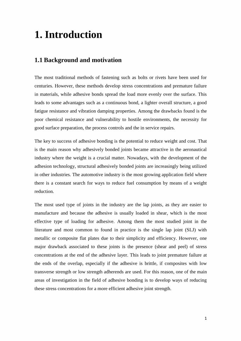
The most traditional methods of fastening such as bolts or rivets have been used for
centuries. However, these methods develop stress concentrations and premature failure
in materials, while adhesive bonds spread the load more evenly over the surface. This
leads to some advantages such as a continuous bond, a lighter overall structure, a good
fatigue resistance and vibration damping properties. Among the drawbacks found is the
poor chemical resistance and vulnerability to hostile environments, the necessity for
good surface preparation, the process controls and the in service repairs.
The key to success of adhesive bonding is the potential to reduce weight and cost. That
is the main reason why adhesively bonded joints became attractive in the aeronautical
industry where the weight is a crucial matter. Nowadays, with the development of the
adhesion technology, structural adhesively bonded joints are increasingly being utilized
in other industries. The automotive industry is the most growing application field where
there is a constant search for ways to reduce fuel consumption by means of a weight
reduction.
The most used type of joints in the industry are the lap joints, as they are easier to
manufacture and because the adhesive is usually loaded in shear, which is the most
effective type of loading for adhesive. Among them the most studied joint in the
literature and most common to found in practice is the single lap joint (SLJ) with
metallic or composite flat plates due to their simplicity and efficiency. However, one
major drawback associated to these joints is the presence (shear and peel) of stress
concentrations at the end of the adhesive layer. This leads to joint premature failure at
the ends of the overlap, especially if the adhesive is brittle, if composites with low
transverse strength or low strength adherends are used. For this reason, one of the main
areas of investigation in the field of adhesive bonding is to develop ways of reducing
these stress concentrations for a more efficient adhesive joint strength.
2
There are many available methods to reduce the stress concentrations and increase the
joint strength. However, one of the most promising techniques and the motivation of
this thesis is the improvement of the joint strength by making use of functionally graded
materials and functionally graded bondlines.
1.2 Objectives
The main objective of this thesis is to obtain a gradual variation of the adhesive
properties in a SLJ through dielectric heating. Hereafter, there are two ways to proceed;
the first idea is to obtain a graded cure of the adhesive using different local
concentrations of microwave absorbing particles (carbon black) along the overlap. The
particles interact with the magnetic field and heat the adhesive. On the other hand, if the
first way does not work, the carbon black can be used to reinforce the adhesive as well.
Therefore, the idea is to obtain graded mechanical properties varying the concentration
of particles along the overlap and cure isothermally by dielectric heating.
Specifically, the objectives are:
To determine the viability of the main objectives and select the best way to
proceed;
To determine the effect of the concentration of two types of carbon black
particles in the adhesive properties;
To manufacture graded joints in a controlled and repetitive way;
To test statically graded joints and compare their strength with joints that have
uniform properties;
1.3 Research methodology
In order to achieve the aim of this thesis, the following work had to be defined:
1) To do a bibliographic research on the topic of adhesive joints and ways to
improve the joint strength;
2) To study the dielectric heating technology and the interaction with the
adhesives and the carbon black particles;
1. INTRODUCTION
3
3) To do a review of the properties of carbon black particles and the effect in
the adhesive properties;
4) To do a preliminary experimentation in order to determine the viability of
main objectives;
5) To manufacture bulk specimens and characterize the adhesive properties as
a function of the amount of carbon black particles;
6) To manufacture graded joints in a controlled and repetitive way and
compare their strength with joints that have uniform properties.
1.4 Thesis outline
The outline of this thesis is the following:
Chapter 2: An introductory literature review of adhesives in general is made, focusing
on their historical development, some important definitions, advantages and
disadvantages. Also several methods to improve and analyze adhesive joints are
commented. A specific literature review about dielectric heating and carbon black
particles is made as well;
Chapter 3: A summary of the experimental details is made.
Chapter 4: The tensile bulk tests are performed to characterize the adhesive as function
of the carbon black particles and the graded joints are manufactured and tested.
Chapter 5: A failure load prediction is made and compared with the experimental results
Chapter 6 and 7: Conclusions and ideas for future work are presented.

5
2. Literature review
2.1 Adhesive joints
The first reports of the use of adhesives in the human history date from the time of
Mesopotamians in 4000BC. It was a rudimentary technique which used asphalt for
construction purposes. However, by the mid-17th century the bonding industry began to
develop rapidly and, nowadays, structural adhesives have become a valid alternative to
classical mechanical bonding methods such as bolts or rivets [1].
2.1.1 Definitions
An adhesive is any substance applied to the surfaces of materials that binds them
together and resists separation. There are many terms to refer to it: glue, cement,
mucilage, mastic or paste. The intermolecular forces inside the adhesive are called
cohesion [2].
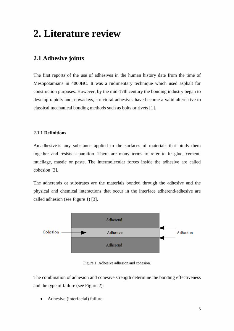
The adherends or substrates are the materials bonded through the adhesive and the
physical and chemical interactions that occur in the interface adherend/adhesive are
called adhesion (see Figure 1) [3].
Figure 1. Adhesive adhesion and cohesion.
The combination of adhesion and cohesive strength determine the bonding effectiveness
and the type of failure (see Figure 2):
Adhesive (interfacial) failure
6
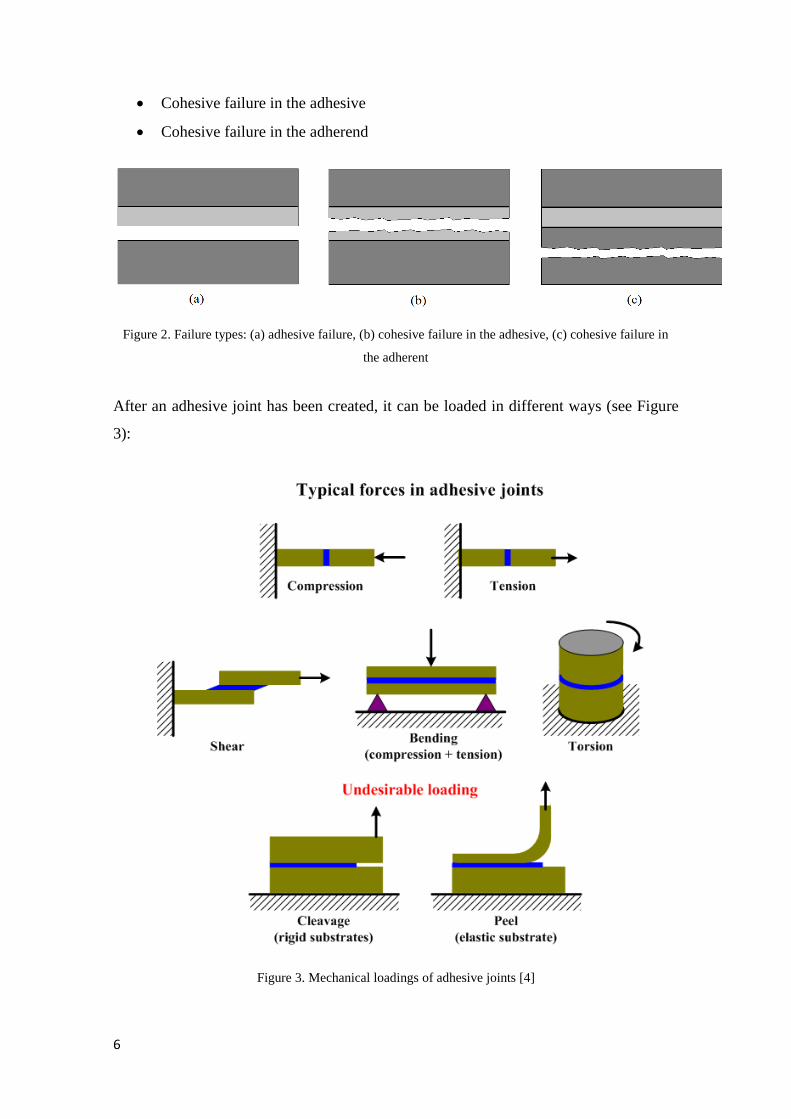
Cohesive failure in the adhesive
Cohesive failure in the adherend
Figure 2. Failure types: (a) adhesive failure, (b) cohesive failure in the adhesive, (c) cohesive failure in
the adherent
After an adhesive joint has been created, it can be loaded in different ways (see Figure
3):
Figure 3. Mechanical loadings of adhesive joints [4]
2. LITERATURE REVIEW
7
In the literature there are several proposed methods to predict the failure of adhesive
joints, but before such calculations can be performed it is first necessary to determine
the mechanical properties of the adhesives [5].
2.1.2 Advantages
Structural adhesive bonding has the following main advantages [3, 6]:
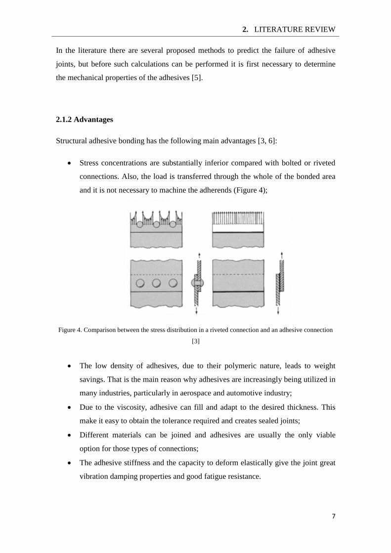
Stress concentrations are substantially inferior compared with bolted or riveted
connections. Also, the load is transferred through the whole of the bonded area
and it is not necessary to machine the adherends (Figure 4);
Figure 4. Comparison between the stress distribution in a riveted connection and an adhesive connection
[3]
The low density of adhesives, due to their polymeric nature, leads to weight
savings. That is the main reason why adhesives are increasingly being utilized in
many industries, particularly in aerospace and automotive industry;
Due to the viscosity, adhesive can fill and adapt to the desired thickness. This
make it easy to obtain the tolerance required and creates sealed joints;
Different materials can be joined and adhesives are usually the only viable
option for those types of connections;
The adhesive stiffness and the capacity to deform elastically give the joint great
vibration damping properties and good fatigue resistance.
8
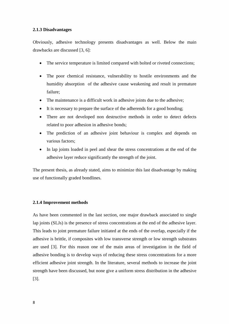
2.1.3 Disadvantages
Obviously, adhesive technology presents disadvantages as well. Below the main
drawbacks are discussed [3, 6]:
The service temperature is limited compared with bolted or riveted connections;
The poor chemical resistance, vulnerability to hostile environments and the
humidity absorption of the adhesive cause weakening and result in premature
failure;
The maintenance is a difficult work in adhesive joints due to the adhesive;
It is necessary to prepare the surface of the adherends for a good bonding;
There are not developed non destructive methods in order to detect defects
related to poor adhesion in adhesive bonds;
The prediction of an adhesive joint behaviour is complex and depends on
various factors;
In lap joints loaded in peel and shear the stress concentrations at the end of the
adhesive layer reduce significantly the strength of the joint.
The present thesis, as already stated, aims to minimize this last disadvantage by making
use of functionally graded bondlines.
2.1.4 Improvement methods
As have been commented in the last section, one major drawback associated to single
lap joints (SLJs) is the presence of stress concentrations at the end of the adhesive layer.
This leads to joint premature failure initiated at the ends of the overlap, especially if the
adhesive is brittle, if composites with low transverse strength or low strength substrates
are used [3]. For this reason one of the main areas of investigation in the field of
adhesive bonding is to develop ways of reducing these stress concentrations for a more
efficient adhesive joint strength. In the literature, several methods to increase the joint
strength have been discussed, but none give a uniform stress distribution in the adhesive
[3].
2. LITERATURE REVIEW
9
Lap joints and specifically the SLJs have several factors that affect the joint strength.
The material properties (adherend and adhesive) and the geometry (adherend and
adhesive thickness, and overlap) are the most outstanding and, mostly, improvement
methods are related to these.
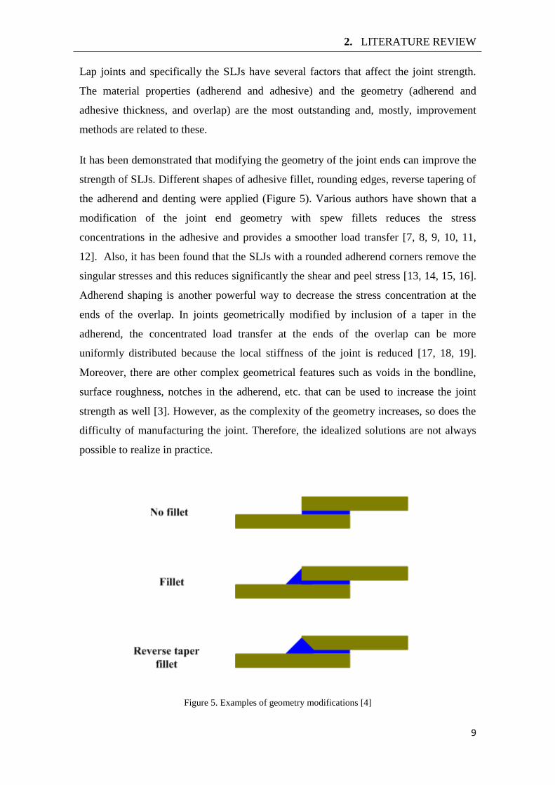
It has been demonstrated that modifying the geometry of the joint ends can improve the
strength of SLJs. Different shapes of adhesive fillet, rounding edges, reverse tapering of
the adherend and denting were applied (Figure 5). Various authors have shown that a
modification of the joint end geometry with spew fillets reduces the stress
concentrations in the adhesive and provides a smoother load transfer [7, 8, 9, 10, 11,
12]. Also, it has been found that the SLJs with a rounded adherend corners remove the
singular stresses and this reduces significantly the shear and peel stress [13, 14, 15, 16].
Adherend shaping is another powerful way to decrease the stress concentration at the
ends of the overlap. In joints geometrically modified by inclusion of a taper in the
adherend, the concentrated load transfer at the ends of the overlap can be more
uniformly distributed because the local stiffness of the joint is reduced [17, 18, 19].
Moreover, there are other complex geometrical features such as voids in the bondline,
surface roughness, notches in the adherend, etc. that can be used to increase the joint
strength as well [3]. However, as the complexity of the geometry increases, so does the
difficulty of manufacturing the joint. Therefore, the idealized solutions are not always
possible to realize in practice.
Figure 5. Examples of geometry modifications [4]
10
Another technique is the hybrid joint which includes mixed adhesive joints. This joint
consists in using a stiff and strong adhesive in the middle of the overlap and a flexible
and ductile adhesive at the ends of the overlap. This leads to a more uniform
distribution of the stresses and improves the joint strength [20, 21, 22, 23, 24, 25, 26].
Some successful investigations are the theoretical and experimental study of dual
adhesives in metal/composite joints by da Silva and Adams [11]. Also, Fitton and
Broughton [26] determined that a variable adhesive modulus along the overlap reduces
the stress concentration and improve the joint strength. Other authors, Marques and da
Silva [19], Marques et al. [22] and da Silva and Lopes [25], have demonstrated joint
strength improvements as well.
Now, the studies are focusing on the improvement of the joint strength by making use
of functionally graded materials and functionally graded bondlines. One of the first tries
was to use functionally graded adherends. Ganesh and Choo [27] and Boss et al. [28]
obtained a 20% increase in the joint strength by braided performs with continuously
varying braid angle. Apalak and Gunes [29] studied the flexural behaviour of an
adhesively bonded SLJ with adherends composed of a functionally gradient layer
between a pure ceramic layer and pure metal layer. The studies were not supported with
experimental results and the adhesive stress distribution was not hugely affected.
Other authors have tried to modify the adhesive properties along the overlap, Sancaktar
and Kumar [30] graded the adhesive by making rubber toughened regions, and found
that the selective toughening increased the joint strength. Stapleton et al. [31] used glass
beads strategically placed within the adhesive layer in order to obtain different densities
and change the stiffness along the overlap. This technique substantially reduces the peel
stress concentrations. More recently, Carbas et al. [32, 33] studied the effect of adhesive
properties as a function of the cure temperature and achieved a functionally graded cure
along the overlap by induction heating. The functionally graded joints exhibited a
higher joint strength compared to the cases where the adhesive was cured uniformly at
low temperature or at high temperature.
2. LITERATURE REVIEW
11
2.2 Analysis of adhesive joints
The most studied joint in the literature and also most commonly found in practice is the
SLJ, with metallic or composite adherends, due to its simplicity and efficiency. For this
reason, ways to predict the joint strength have been intensively investigated over the
past 70 years and numerous analytical models have been proposed [5].
For this work, the linear elastic analysis and the Volkersen´s analysis can be used to
predict the failure load of the SLJs with uniform properties. For the graded joints, a
functionally graded joint analytical model has to be used.
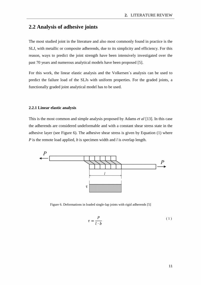
2.2.1 Linear elastic analysis
This is the most common and simple analysis proposed by Adams et al [13]. In this case
the adherends are considered undeformable and with a constant shear stress state in the
adhesive layer (see Figure 6). The adhesive shear stress is given by Equation (1) where
P is the remote load applied, b is specimen width and l is overlap length.
Figure 6. Deformations in loaded single-lap joints with rigid adherends [5]
( 1 )
12
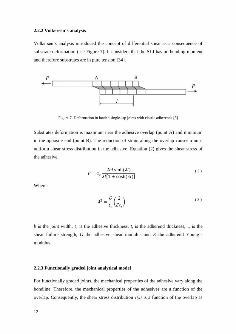
2.2.2 Volkersen´s analysis
Volkersen’s analysis introduced the concept of differential shear as a consequence of
substrate deformation (see Figure 7). It considers that the SLJ has no bending moment
and therefore substrates are in pure tension [34].
Figure 7. Deformation in loaded single-lap joints with elastic adherends [5]
Substrates deformation is maximum near the adhesive overlap (point A) and minimum
in the opposite end (point B). The reduction of strain along the overlap causes a non-
uniform shear stress distribution in the adhesive. Equation (2) gives the shear stress of
the adhesive.
( 2 )
Where:
( 3 )
b is the joint width, ta is the adhesive thickness, ts is the adherend thickness, τr is the
shear failure strength, G the adhesive shear modulus and E the adherend Young’s
modulus.
2.2.3 Functionally graded joint analytical model
For functionally graded joints, the mechanical properties of the adhesive vary along the
bondline. Therefore, the mechanical properties of the adhesives are a function of the
overlap. Consequently, the shear stress distribution τ(x) is a function of the overlap as

2. LITERATURE REVIEW
13
well. Carbas et al. [35] developed a simple analytical model to study the performance of
the functionally graded joints.
The development of this analytical model, based on Volkersen’s analysis [34], was
solved with power series expansion for a reduced number of expansion terms (21
terms). Equation (4) represents the adhesive shear stress as a function of the overlap
using 2 terms of the power series expansion in order to reduce the complexity of the
equation.
( 4 )
Where P is the applied load, m is the slope and K is the constant (y-intercept) of the
linear adhesive shear modulus variation along the bondline.
14
2.3 Dielectric heating
As already stated, in the present thesis the cure of the adhesive will be done by
dielectric heating. Therefore, is important to understand how the microwaves work.
Hence, the microwave fundamentals and some studies about dielectric are discussed
below.
2.3.1 Introduction
Nowadays, is difficult to find a kitchen without a microwave oven. The faster cooking
times and energy savings over conventional cooking methods have made the microwave
an essential appliance. Although the use of microwaves for cooking food is widespread,
the application of this technology for processing materials is relatively new and it is still
being developed. The use of microwave energy for processing materials has the
potential to offer similar advantages in reduced processing times and energy savings.
The energy supplied by conventional heating methods is transferred from the surfaces of
the materials through convection, conduction, and radiation. On the other hand, the
microwave energy is transferred by the interaction of the electromagnetic fields with the
molecules of the material. Therefore, the heat is generated throughout the volume of the
material.
Furthermore, in addition to volumetric heating, the microwaves have some additional
advantages. Microwaves can be utilized for selective heating of materials. The
molecular structure affects the ability of the microwaves to interact with materials and
transfer energy. When materials in contact are heated, microwaves will selectively
couple with the material with higher dielectric properties. This phenomenon of selective
heating can be used for a number of purposes. One of them has been proposed in the
main objectives.
Naturally, every technology presents disadvantages, and the dielectric heating is not an
exception. Therefore, the different mechanism of energy transfer in microwave heating
has also resulted in two main drawbacks:
2. LITERATURE REVIEW
15
The non-uniformity of the electromagnetic field will result in non-uniform
heating;
Due to the physical and structural transformations during the process, the
dielectric properties and the ability of microwaves to generate heat vary.
These disadvantages lead to difficulties with process modelling and control. Therefore,
understanding the generation, propagation, and interaction of microwaves with
materials is critical [36].
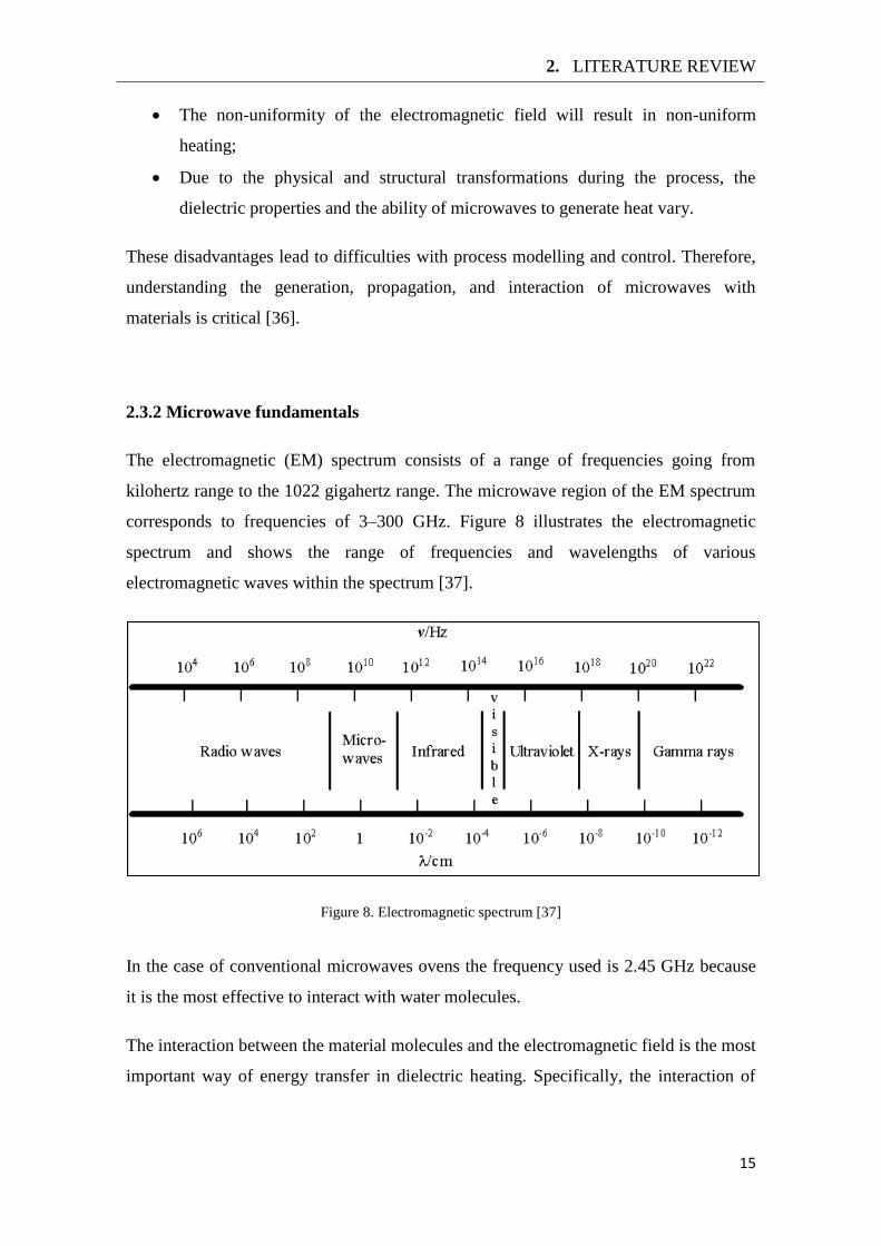
2.3.2 Microwave fundamentals
The electromagnetic (EM) spectrum consists of a range of frequencies going from
kilohertz range to the 1022 gigahertz range. The microwave region of the EM spectrum
corresponds to frequencies of 3–300 GHz. Figure 8 illustrates the electromagnetic
spectrum and shows the range of frequencies and wavelengths of various
electromagnetic waves within the spectrum [37].
Figure 8. Electromagnetic spectrum [37]
In the case of conventional microwaves ovens the frequency used is 2.45 GHz because
it is the most effective to interact with water molecules.
The interaction between the material molecules and the electromagnetic field is the most
important way of energy transfer in dielectric heating. Specifically, the interaction of
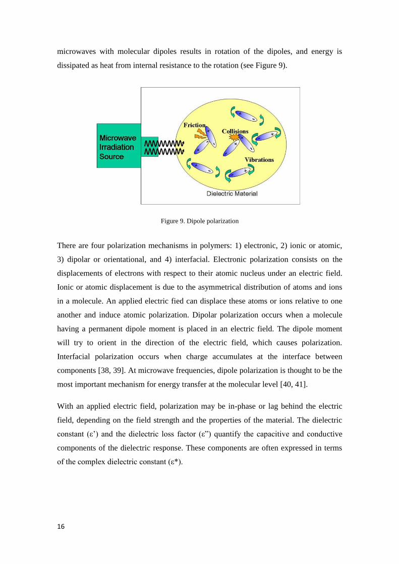
16
microwaves with molecular dipoles results in rotation of the dipoles, and energy is
dissipated as heat from internal resistance to the rotation (see Figure 9).
Figure 9. Dipole polarization
There are four polarization mechanisms in polymers: 1) electronic, 2) ionic or atomic,
3) dipolar or orientational, and 4) interfacial. Electronic polarization consists on the
displacements of electrons with respect to their atomic nucleus under an electric field.
Ionic or atomic displacement is due to the asymmetrical distribution of atoms and ions
in a molecule. An applied electric fied can displace these atoms or ions relative to one
another and induce atomic polarization. Dipolar polarization occurs when a molecule
having a permanent dipole moment is placed in an electric field. The dipole moment
will try to orient in the direction of the electric field, which causes polarization.
Interfacial polarization occurs when charge accumulates at the interface between
components [38, 39]. At microwave frequencies, dipole polarization is thought to be the
most important mechanism for energy transfer at the molecular level [40, 41].
With an applied electric field, polarization may be in-phase or lag behind the electric
field, depending on the field strength and the properties of the material. The dielectric
constant (ε’) and the dielectric loss factor (ε”) quantify the capacitive and conductive
components of the dielectric response. These components are often expressed in terms
of the complex dielectric constant (ε*).
2. LITERATURE REVIEW
17
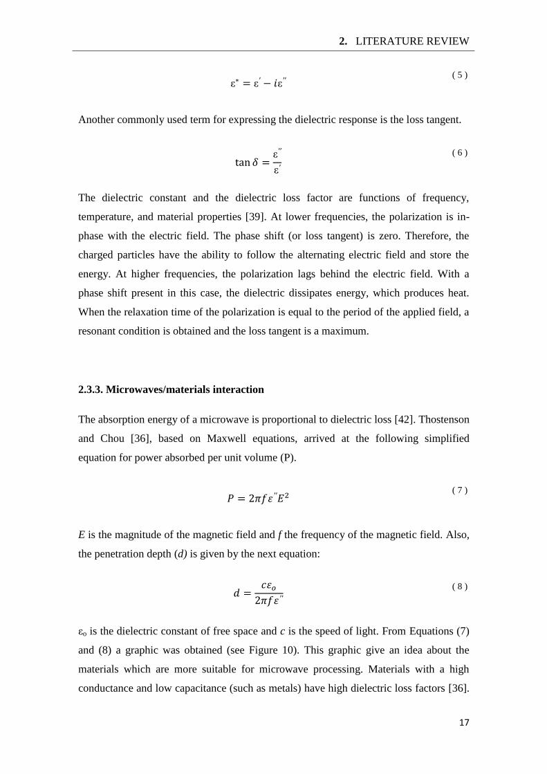
ε ε ε ( 5 )
Another commonly used term for expressing the dielectric response is the loss tangent.
ε
ε
( 6 )
The dielectric constant and the dielectric loss factor are functions of frequency,
temperature, and material properties [39]. At lower frequencies, the polarization is in-
phase with the electric field. The phase shift (or loss tangent) is zero. Therefore, the
charged particles have the ability to follow the alternating electric field and store the
energy. At higher frequencies, the polarization lags behind the electric field. With a
phase shift present in this case, the dielectric dissipates energy, which produces heat.
When the relaxation time of the polarization is equal to the period of the applied field, a
resonant condition is obtained and the loss tangent is a maximum.
2.3.3. Microwaves/materials interaction
The absorption energy of a microwave is proportional to dielectric loss [42]. Thostenson
and Chou [36], based on Maxwell equations, arrived at the following simplified
equation for power absorbed per unit volume (P).
( 7 )
E is the magnitude of the magnetic field and f the frequency of the magnetic field. Also,
the penetration depth (d) is given by the next equation:
( 8 )
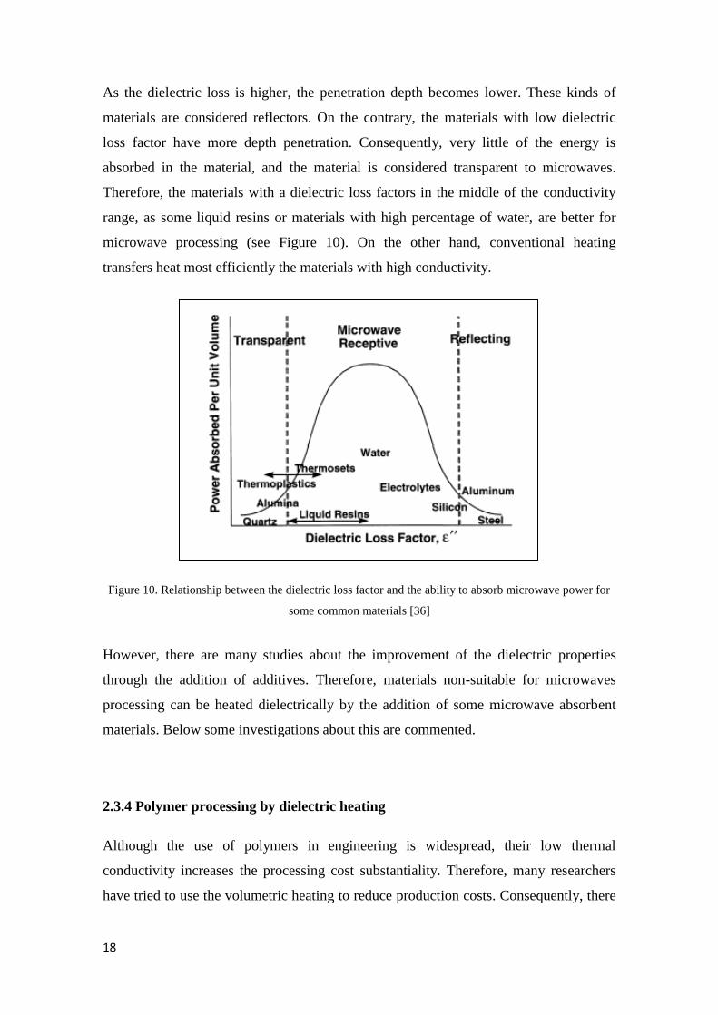
εo is the dielectric constant of free space and c is the speed of light. From Equations (7)
and (8) a graphic was obtained (see Figure 10). This graphic give an idea about the
materials which are more suitable for microwave processing. Materials with a high
conductance and low capacitance (such as metals) have high dielectric loss factors [36].
18
As the dielectric loss is higher, the penetration depth becomes lower. These kinds of
materials are considered reflectors. On the contrary, the materials with low dielectric
loss factor have more depth penetration. Consequently, very little of the energy is
absorbed in the material, and the material is considered transparent to microwaves.
Therefore, the materials with a dielectric loss factors in the middle of the conductivity
range, as some liquid resins or materials with high percentage of water, are better for
microwave processing (see Figure 10). On the other hand, conventional heating
transfers heat most efficiently the materials with high conductivity.
Figure 10. Relationship between the dielectric loss factor and the ability to absorb microwave power for
some common materials [36]
However, there are many studies about the improvement of the dielectric properties
through the addition of additives. Therefore, materials non-suitable for microwaves
processing can be heated dielectrically by the addition of some microwave absorbent
materials. Below some investigations about this are commented.
2.3.4 Polymer processing by dielectric heating
Although the use of polymers in engineering is widespread, their low thermal
conductivity increases the processing cost substantiality. Therefore, many researchers
have tried to use the volumetric heating to reduce production costs. Consequently, there
2. LITERATURE REVIEW
19
has been much investigation about polymers and composites processing by dielectric
heating.
Basically, the literature can be divided into two main categories: cure kinetics and
physical properties. Otherwise, the studies are focused in the effect of microwaves in
the cure time and the mechanical properties of polymers.
Cure kinetics
A study about the rate reactions during cure of epoxy resin systems have been done by
Marand et al. [43], Wei et al. [44], and Jordan et al. [45]. All the authors agree with the
cure time reduction. Furthermore, Marand et al. [43] showed that the molecular
structure of the resin and the hardener affect the microwave heating. Following this line
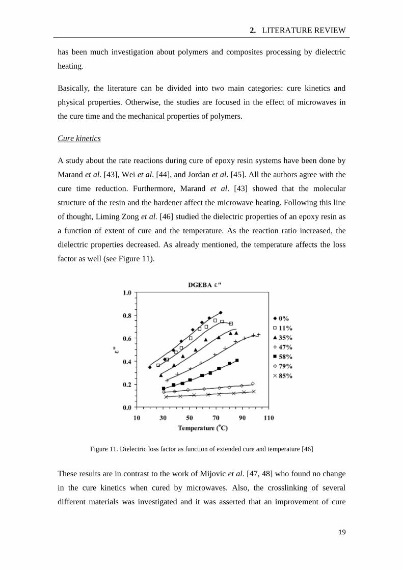
of thought, Liming Zong et al. [46] studied the dielectric properties of an epoxy resin as
a function of extent of cure and the temperature. As the reaction ratio increased, the
dielectric properties decreased. As already mentioned, the temperature affects the loss
factor as well (see Figure 11).
Figure 11. Dielectric loss factor as function of extended cure and temperature [46]
These results are in contrast to the work of Mijovic et al. [47, 48] who found no change
in the cure kinetics when cured by microwaves. Also, the crosslinking of several
different materials was investigated and it was asserted that an improvement of cure
20
kinetics is unfounded. The conflicting results by different laboratories indicate the need
for additional work in this area.
Physical properties
From a different perspective, Wei et al. [44] tried to determine the effects of
microwaves on the molecular structure, and they observed that the molecular structure
of some polymers is different when cured using microwaves as compared with
conventional curing. Thereafter, some researchers became interested in the effect of
microwaves on the molecular structure of the polymer and the resulting mechanical
properties. Singer et al. [49] compared the mechanical properties of an epoxy resin
under microwave and thermal cure. The tensile strength of the specimens cured by
microwave and with a degree of cure below 80% was significantly lower than thermally
cured specimens. However, when the extent of cure increased until 100% the tensile
strength of the microwave specimens surpassed the thermally cured. Moreover, the
Young’s modulus was a bit higher in the microwave cured specimens. The authors
postulated that the behaviour of the tensile strength and the modulus is due to the higher
molecular packing with lower free volume as result of alignment of the polymer
network in the magnetic field. The results of this investigation coincide with the results
of Bai et al. [50]. On the other hand, Jordan et al. [45] didn't found any change in the
elastic properties of epoxy resins cured under microwaves.
2.3.5 Dielectric heating systems
The previous sections discussed the processing of polymers, but it is interesting to give
information about the available appliances to generate dielectric heating. Therefore,
although the device used in the present work is a conventional microwave oven, a
research about this gives a wider vision of the available options.
Fixed Frequency Microwave Systems
Microwaves are commonly generated by magnetrons or klystrons with different power
outputs. These devices can produce continuous or pulsed wave oscillation of a unique
2. LITERATURE REVIEW
21
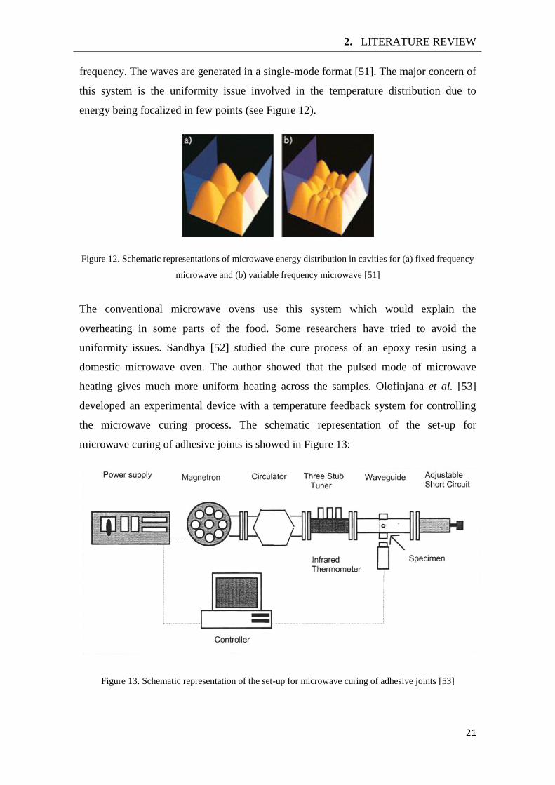
frequency. The waves are generated in a single-mode format [51]. The major concern of
this system is the uniformity issue involved in the temperature distribution due to
energy being focalized in few points (see Figure 12).
Figure 12. Schematic representations of microwave energy distribution in cavities for (a) fixed frequency
microwave and (b) variable frequency microwave [51]
The conventional microwave ovens use this system which would explain the
overheating in some parts of the food. Some researchers have tried to avoid the
uniformity issues. Sandhya [52] studied the cure process of an epoxy resin using a
domestic microwave oven. The author showed that the pulsed mode of microwave
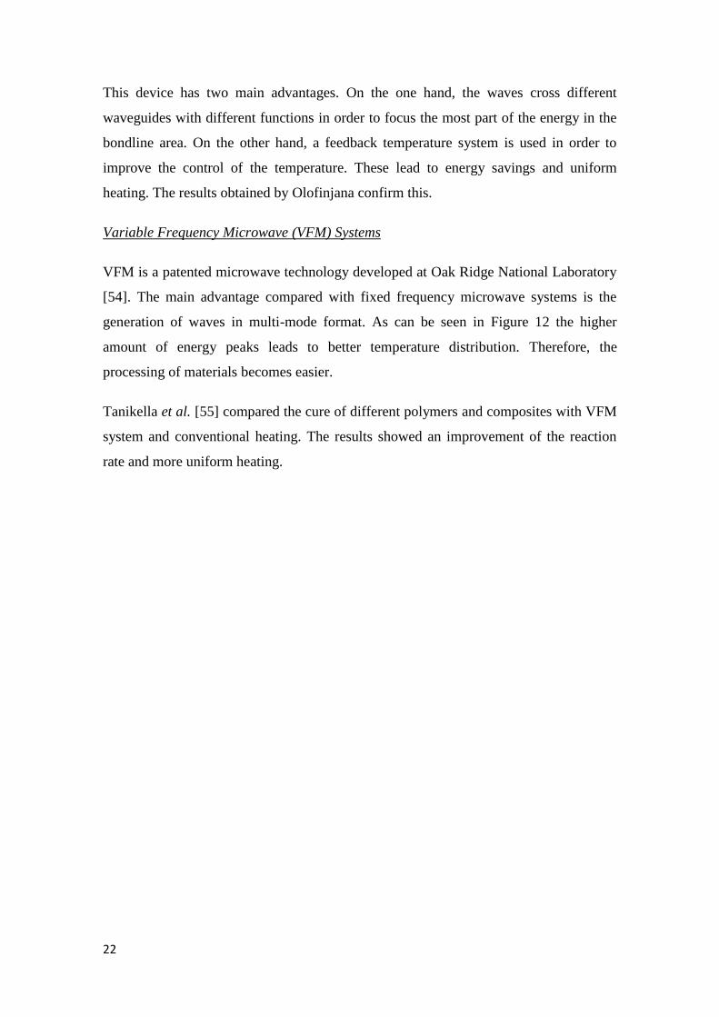
heating gives much more uniform heating across the samples. Olofinjana et al. [53]
developed an experimental device with a temperature feedback system for controlling
the microwave curing process. The schematic representation of the set-up for
microwave curing of adhesive joints is showed in Figure 13:
Figure 13. Schematic representation of the set-up for microwave curing of adhesive joints [53]
22
This device has two main advantages. On the one hand, the waves cross different
waveguides with different functions in order to focus the most part of the energy in the
bondline area. On the other hand, a feedback temperature system is used in order to
improve the control of the temperature. These lead to energy savings and uniform
heating. The results obtained by Olofinjana confirm this.
Variable Frequency Microwave (VFM) Systems
VFM is a patented microwave technology developed at Oak Ridge National Laboratory
[54]. The main advantage compared with fixed frequency microwave systems is the
generation of waves in multi-mode format. As can be seen in Figure 12 the higher
amount of energy peaks leads to better temperature distribution. Therefore, the
processing of materials becomes easier.
Tanikella et al. [55] compared the cure of different polymers and composites with VFM
system and conventional heating. The results showed an improvement of the reaction
rate and more uniform heating.
2. LITERATURE REVIEW
23
2.4 Polymer reinforcement
As already stated, the present thesis aims to obtain gradual mechanical properties along
the overlap. One way to achieve the objective is to use carbon black nanoparticles and
try to change the physical properties of the adhesive. For this reason, in order to know
the effect of particles in the adhesive a research was carried out.
2.4.1 Additives
The use of polymers has substantially expanded during the last years. However, the
limitations are obvious and the requirements of most engineering applications are
increasing. Therefore, a considerable effort has been devoted to improve the properties
and quality of the composite materials. One of the best ways to reach the requirements
is the addition of additives and the result is called polymer composites.
The primary reasons for using additives are: properties modification or enhancement,
overall cost reduction, improving and controlling of processing characteristics. The
additives can be inorganic or organic and have several geometries (fibers, flakes,
spheres or particles) [56].
Basically, there are two main research fields which coincide with main limitations of the
polymers. The first is to enhance the low thermal and electric conductivity of polymers.
The second is to improve the low mechanical properties. Also, other additives like
flame retardants or pigments can be added to the polymer as a function of the final
application.
Conductivity
The required conductivity properties can be achieved by the incorporation of highly
conductive fillers. The most commons are carbon black particles, metallic particles or
carbon fibers.
24
Mechanical properties
The literature about the improvement of mechanical properties of polymers is wide. The
most typical reinforced polymers are the CFRP (carbon fiber reinforced polymer) and
the GFRP (glass fiber reinforced polymer or fibreglass) due to their higher mechanical
properties. Also, other additives as carbon black or silica particles are specially used to
reinforce the rubber of the automotive tires [57].
2.4.2 Carbon black
Since the carbon black particles are an important factor of the present work, it is
essential to know more about them. As already mentioned, the carbon black particles
have the potential to improve the conductive and the mechanical properties of polymers
and can also be used as pigments. Therefore, the properties of carbon black particles and
the studies of some authors are commented below.
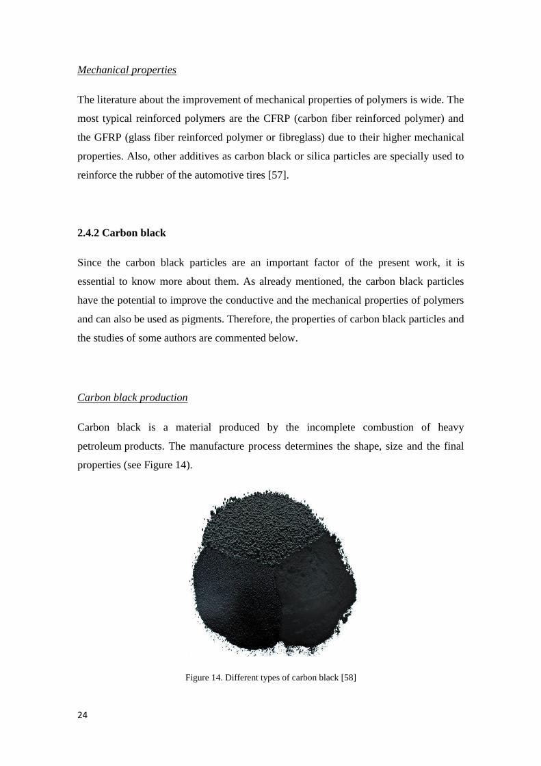
Carbon black production
Carbon black is a material produced by the incomplete combustion of heavy
petroleum products. The manufacture process determines the shape, size and the final
properties (see Figure 14).
Figure 14. Different types of carbon black [58]
2. LITERATURE REVIEW
25
Dielectric properties of carbon black
Since the great microwave absorption properties of carbon black particles were
discovered, two main practical applications have been developed. The first is to reduce
the increasing electromagnetic (EM) interference problems. The second is to allow the
dielectric processing of the materials which are not suitable to heat with microwaves.
Liu et al. [59] studied the absorption properties of carbon black composite at different
frequencies. The results show excellent microwave absorption properties in the 2–18
GHz frequency range with a reduction of dielectric properties as frequency increases.
Also, the best results were obtained for 5 wt.% of carbon black. The results of this
investigation are consistent with the results of Wui et al. [60].
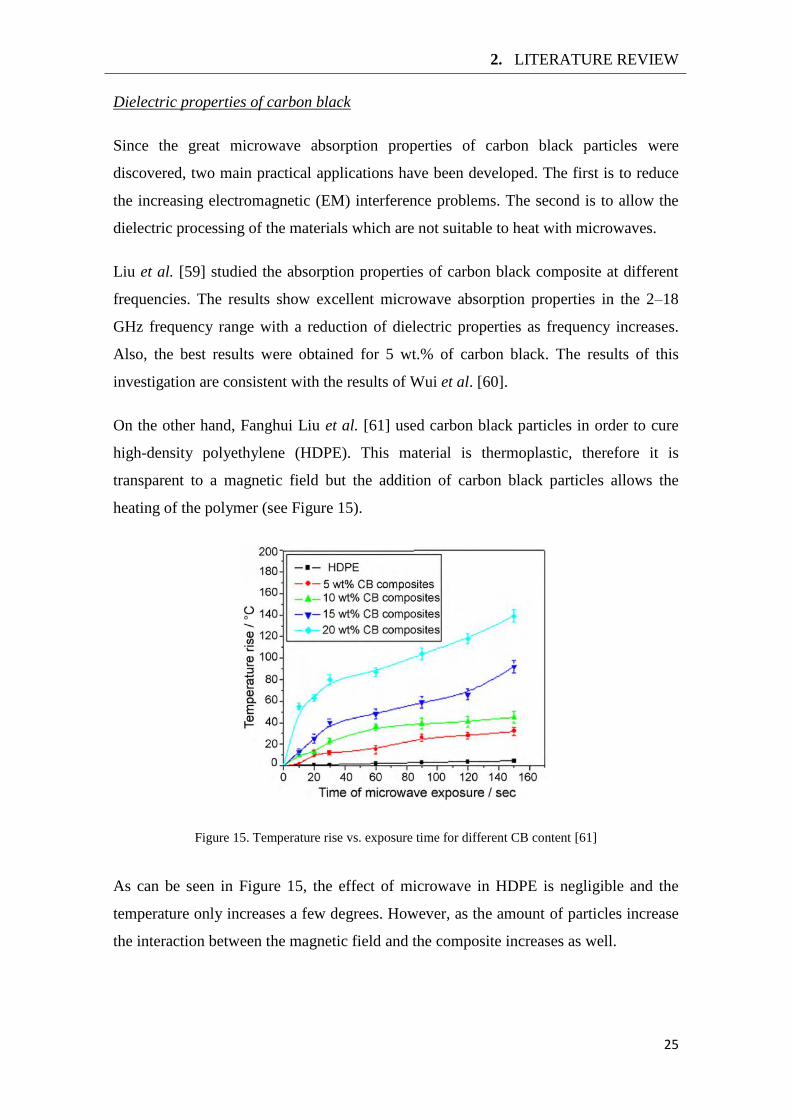
On the other hand, Fanghui Liu et al. [61] used carbon black particles in order to cure
high-density polyethylene (HDPE). This material is thermoplastic, therefore it is
transparent to a magnetic field but the addition of carbon black particles allows the
heating of the polymer (see Figure 15).
Figure 15. Temperature rise vs. exposure time for different CB content [61]
As can be seen in Figure 15, the effect of microwave in HDPE is negligible and the
temperature only increases a few degrees. However, as the amount of particles increase
the interaction between the magnetic field and the composite increases as well.
26
Surface properties of carbon black
Vilgis et al [57] claim that the reinforcing potential is mainly attributed to two effects:
(i) the formation of a physically bonded flexible filler network and (ii) strong polymer–
filler couplings. Otherwise, not only the polymer-filler coupling is important. The
interaction between carbon black particles plays an essential role and seems that a
flexible filler network affect significantly the final properties of the filled polymer.
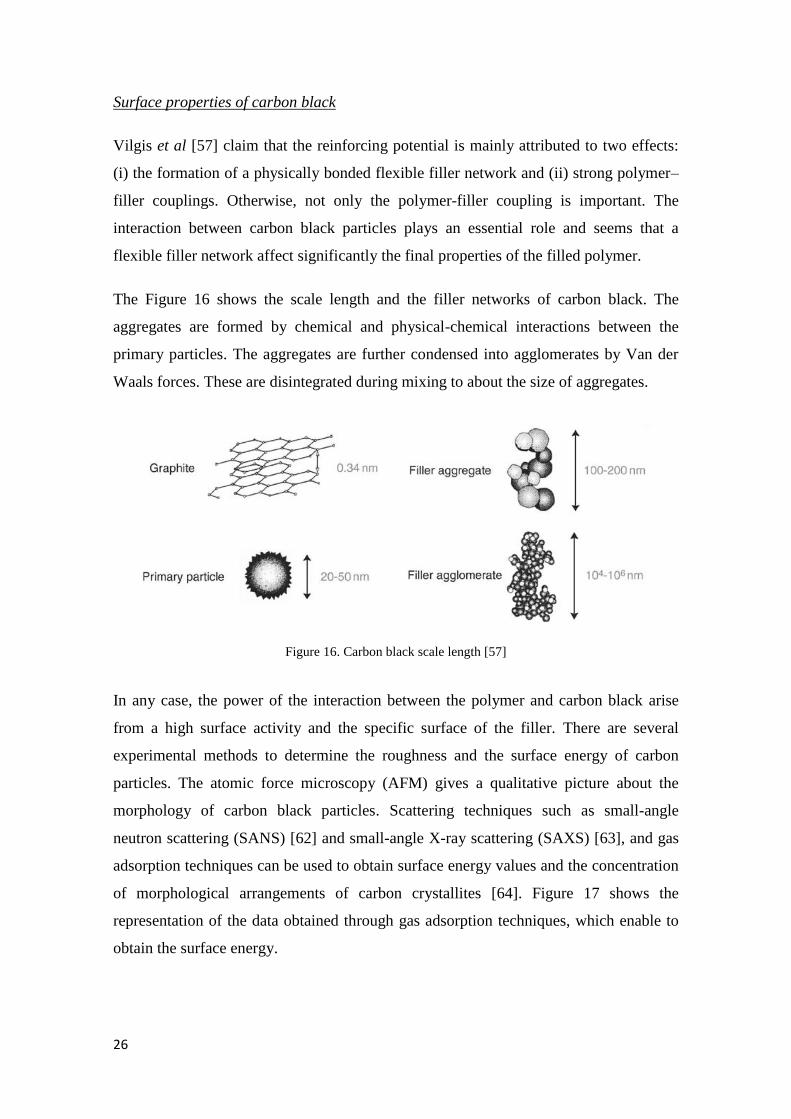
The Figure 16 shows the scale length and the filler networks of carbon black. The
aggregates are formed by chemical and physical-chemical interactions between the
primary particles. The aggregates are further condensed into agglomerates by Van der
Waals forces. These are disintegrated during mixing to about the size of aggregates.
Figure 16. Carbon black scale length [57]
In any case, the power of the interaction between the polymer and carbon black arise
from a high surface activity and the specific surface of the filler. There are several
experimental methods to determine the roughness and the surface energy of carbon
particles. The atomic force microscopy (AFM) gives a qualitative picture about the
morphology of carbon black particles. Scattering techniques such as small-angle
neutron scattering (SANS) [62] and small-angle X-ray scattering (SAXS) [63], and gas
adsorption techniques can be used to obtain surface energy values and the concentration
of morphological arrangements of carbon crystallites [64]. Figure 17 shows the
representation of the data obtained through gas adsorption techniques, which enable to
obtain the surface energy.
2. LITERATURE REVIEW
27
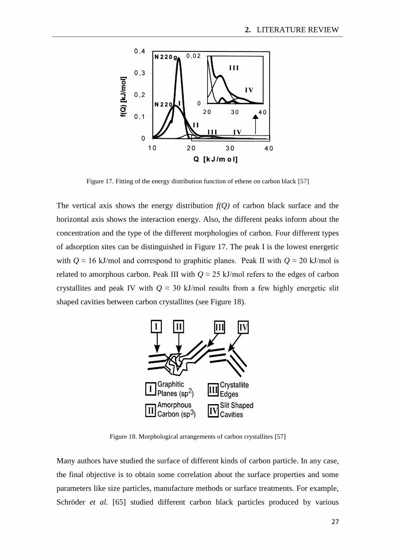
Figure 17. Fitting of the energy distribution function of ethene on carbon black [57]
The vertical axis shows the energy distribution f(Q) of carbon black surface and the
horizontal axis shows the interaction energy. Also, the different peaks inform about the
concentration and the type of the different morphologies of carbon. Four different types
of adsorption sites can be distinguished in Figure 17. The peak I is the lowest energetic
with Q ≈ 16 kJ/mol and correspond to graphitic planes. Peak II with Q ≈ 20 kJ/mol is
related to amorphous carbon. Peak III with Q ≈ 25 kJ/mol refers to the edges of carbon
crystallites and peak IV with Q ≈ 30 kJ/mol results from a few highly energetic slit
shaped cavities between carbon crystallites (see Figure 18).
Figure 18. Morphological arrangements of carbon crystallites [57]
Many authors have studied the surface of different kinds of carbon particle. In any case,
the final objective is to obtain some correlation about the surface properties and some
parameters like size particles, manufacture methods or surface treatments. For example,
Schröder et al. [65] studied different carbon black particles produced by various

28
manufacturing processes and obtained a clear difference between the different carbon
black particles. Donnet et al. [66] and Papirer et al. [67] use different methods to obtain
the surface properties and they observed different results as function of the technique
used.
Therefore, it seems that the reinforcement of composite materials with carbon black is
far from being a simple problem. However, it is clear that the surface structure of
carbon black plays a very important role and is essential in order to understand the
behaviour of the experimentations.
29
3. Experimental details
The final objective of the present thesis is to obtain an improvement of the joint strength
by making use of functionally graded bondline and heating through microwaves.
However, two ways to achieve this have been proposed and therefore is necessary to do
several previous steps in order to find the best way to proceed. After, in order to
characterize the effect of carbon black particles in the adhesive properties, bulk
specimens were manufactured and tested. Finally, the graded joints were manufactured
in a controlled and repeatable way, statically tested and their test results compared with
joints that have uniform properties.
3.1 Adhesive
The adhesive is the most important part of an adhesive joint project. Therefore, it is
crucial to know how to select the correct adhesive for every case. However, due to the
huge variety of adhesives available, selecting a suitable one requires some experience.
In the case of the present work, it is necessary to find a structural adhesive with a good
variation of the mechanical properties as a function of the cure temperature. The best
choice was presented by the investigation of Carbas et al. [32]. In this paper, the authors
describe the influence of the curing temperature on the physical and mechanical
properties of different structural adhesives. The results show that Araldite® 2011
(Hunstman, Basel, Switzerland) was the adhesive that has the largest variation of the
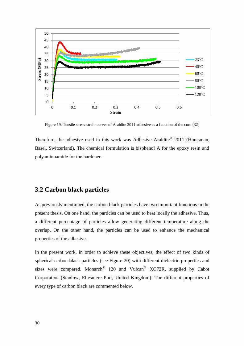
mechanical properties as a function of the cure temperature (see Figure 19).
30
Figure 19. Tensile stress-strain curves of Araldite 2011 adhesive as a function of the cure [32]
Therefore, the adhesive used in this work was Adhesive Araldite® 2011 (Huntsman,
Basel, Switzerland). The chemical formulation is bisphenol A for the epoxy resin and
polyaminoamide for the hardener.
3.2 Carbon black particles
As previously mentioned, the carbon black particles have two important functions in the
present thesis. On one hand, the particles can be used to heat locally the adhesive. Thus,
a different percentage of particles allow generating different temperature along the
overlap. On the other hand, the particles can be used to enhance the mechanical
properties of the adhesive.
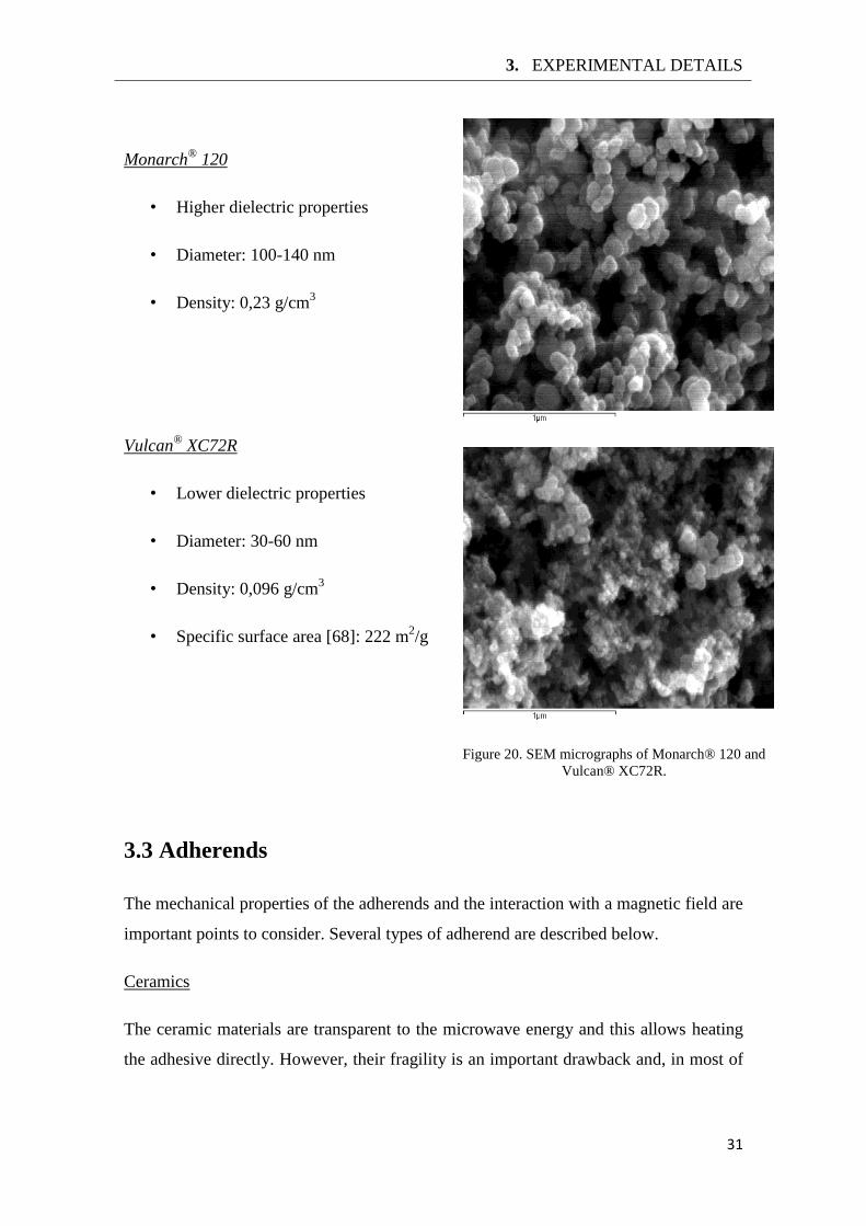
In the present work, in order to achieve these objectives, the effect of two kinds of
spherical carbon black particles (see Figure 20) with different dielectric properties and
sizes were compared. Monarch® 120 and Vulcan
® XC72R, supplied by Cabot
Corporation (Stanlow, Ellesmere Port, United Kingdom). The different properties of
every type of carbon black are commented below.
0
5
10
15
20
25
30
35
40
45
50
0 0.1 0.2 0.3 0.4 0.5 0.6
Str
ess
(MP
a)
Strain
23ºC
40ºC
60ºC
80ºC
100ºC
120ºC
3. EXPERIMENTAL DETAILS
31
Monarch®
120
• Higher dielectric properties
• Diameter: 100-140 nm
• Density: 0,23 g/cm3
Vulcan®
XC72R
• Lower dielectric properties
• Diameter: 30-60 nm
• Density: 0,096 g/cm3
• Specific surface area [68]: 222 m2/g
3.3 Adherends
The mechanical properties of the adherends and the interaction with a magnetic field are
important points to consider. Several types of adherend are described below.
Ceramics
The ceramic materials are transparent to the microwave energy and this allows heating
the adhesive directly. However, their fragility is an important drawback and, in most of
Figure 20. SEM micrographs of Monarch® 120 and
Vulcan® XC72R.
32
the applications where adhesives are used, ceramic materials are not the best option,
especially in the automotive industry.
Polymers
The dielectric properties vary a lot as function of the type of polymer. For this reason,
thermoplastics are a good choice because they are transparent to microwaves. However,
their mechanical properties are relatively low, therefore they cannot be used alone in
most engineering applications.
Polymer composites
Polymer composites have great mechanical properties. However, the dielectric
properties vary as a function of the reinforcing filler. In this study, two typical
composites, CFRP (carbon fibre reinforced polymer) and GFRP (glass fibre reinforced
polymer), were proposed for the preliminary experiments.
Metals
Metallic materials reflect the microwaves and, generally, don’t absorb most part of the
waves. However, if metallic materials have picks or sharp corners, the absorbed energy
is transformed into electric arcs. In order to avoid this, metallic adherends have to be
deburred and their corners rounded [69]. The proposed adherends were aluminium, mild
steel and hard steel.
3.4 Microwave oven
The dielectric heating device used in the present work was a domestic microwave oven.
The frequency generated is 2.45 GHz and the output power ranges from 100 W to 800
W. As already stated, this kind of microwave systems have uniformity issues involved
in the temperature distribution. Therefore, the cure of the adhesives was made by steps
following the recommendations proposed by Sandhya [52].
3. EXPERIMENTAL DETAILS
33
3.5 Temperature control device
The temperature control is an important disadvantage in microwave processing. The
high sensitivity of the electronic devices within an electromagnetic field impedes the
use of conventional measurement methods and real-time control. However, there are
several alternatives for temperature control.
The first and easier way is to open the door of the microwave oven and use a
thermometer or thermocouple. However, this method only provides a local temperature
and it is impossible to check the uniformity of heat.
The second method is to use a fiber optic thermometer. This device can be used in a
strongly electromagnetically influenced environment. Therefore, a real-time control can
be done. However, this method is very expensive and has the same issue that the
thermocouples because it only gives a local temperature.
The last way is to use a thermographic camera, available in the laboratory (Fluke Ti2,
Eindhoven, Netherlands). Although a real-time control can’t be done, controlling the
uniformity of heating is a possibility. For this reason, this was the appliance used during
the experiments.
3.6 Test and manufacture equipment
The Adhesive’s Group laboratory has available all the equipment necessary for testing
and manufacture bulk specimens and SLJs. The mixture of the two components
adhesive with the carbon black particles was done in a mixer machine. The tensile tests
were performed in an INSTRON® model 3367 universal test machine (Norwood,
Massachusetts, USA).

35
4. Results
4.1 Preliminary experiments
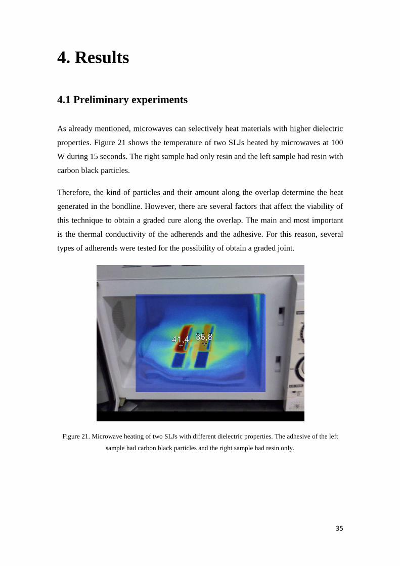
As already mentioned, microwaves can selectively heat materials with higher dielectric
properties. Figure 21 shows the temperature of two SLJs heated by microwaves at 100
W during 15 seconds. The right sample had only resin and the left sample had resin with
carbon black particles.
Therefore, the kind of particles and their amount along the overlap determine the heat
generated in the bondline. However, there are several factors that affect the viability of
this technique to obtain a graded cure along the overlap. The main and most important
is the thermal conductivity of the adherends and the adhesive. For this reason, several
types of adherends were tested for the possibility of obtain a graded joint.
Figure 21. Microwave heating of two SLJs with different dielectric properties. The adhesive of the left
sample had carbon black particles and the right sample had resin only.
36
4.1.1 Graded joints
CFRP
Due to the high concentration of carbon fibre inside the CFRP, when the joint was
heated in the microwave the adherend was hotter than the adhesive bondline. Therefore,
the adhesive layer was cured isothermally by conduction between the adherend and the
adhesive and the graded cure couldn’t be achieved.
GFRP
The glass fibre has a conductivity of 0.03-0.07 W/m·K [70]. Moreover, the glass fibres
are a ceramic material, therefore they are transparent to a magnetic field. However, due
to the low conductivity of the material and the non uniformity of the magnetic field,
localized overheating in different parts of the layer has observed and the graded cure
could not be achieved.
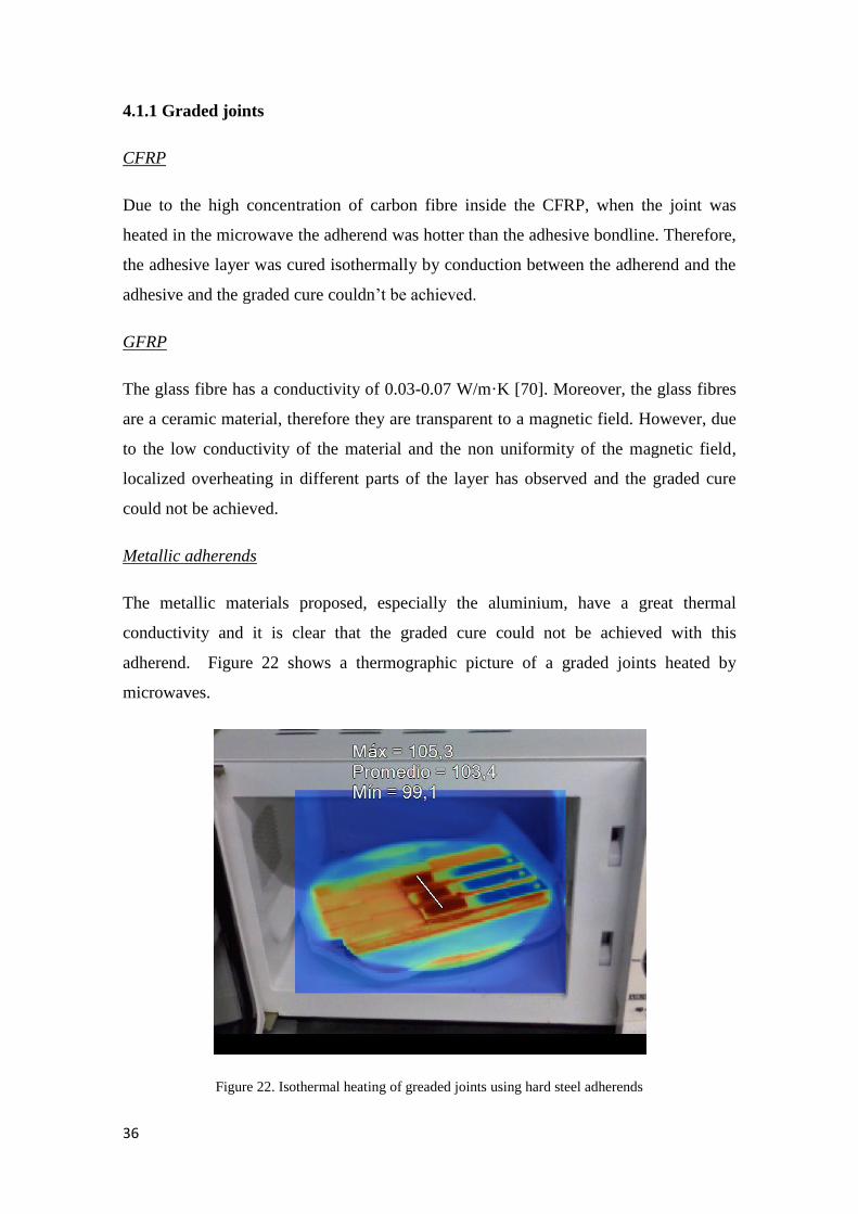
Metallic adherends
The metallic materials proposed, especially the aluminium, have a great thermal
conductivity and it is clear that the graded cure could not be achieved with this
adherend. Figure 22 shows a thermographic picture of a graded joints heated by
microwaves.
Figure 22. Isothermal heating of greaded joints using hard steel adherends
4. RESULTS
37
Therefore, a cooling system, used to ensure greater temperature differences, would be
the best option to obtain a graded cure. However, this is an issue that requires a more
extensive study and the present work contemplates another alternative for obtaining a
graded joint.
As already stated, carbon black particles are good reinforcing fillers. Thus, the idea is to
obtain graded mechanical properties by varying the concentration of particles along the
overlap and cure isothermally by dielectric heating.
4.1.2 Adherend selection
The next step was to select the best option for the adherends. As could be seen in the
previous, the GFRP was discarded immediately due to the overheating of the adhesive.
The high concentration of carbon fibers in CFRP adherends absorbs the most part of
microwaves. Therefore, the adhesive is heated by thermal conduction between the
adherend and the adhesive layer. This lead to higher cure times tend due to the low
thermal conductivity of the adhesive and the adherend. Therefore, the best option for the
adherends was metallic materials because they prevent the overheating of the adhesive
and the times of cure are lower. They are also cheaper than the composite alternatives.
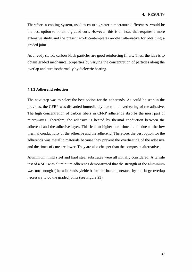
Aluminium, mild steel and hard steel substrates were all initially considered. A tensile
test of a SLJ with aluminium adherends demonstrated that the strength of the aluminium
was not enough (the adherends yielded) for the loads generated by the large overlap
necessary to do the graded joints (see Figure 23).
38
Figure 23. Tensile test of aluminium joint with aluminium yielding
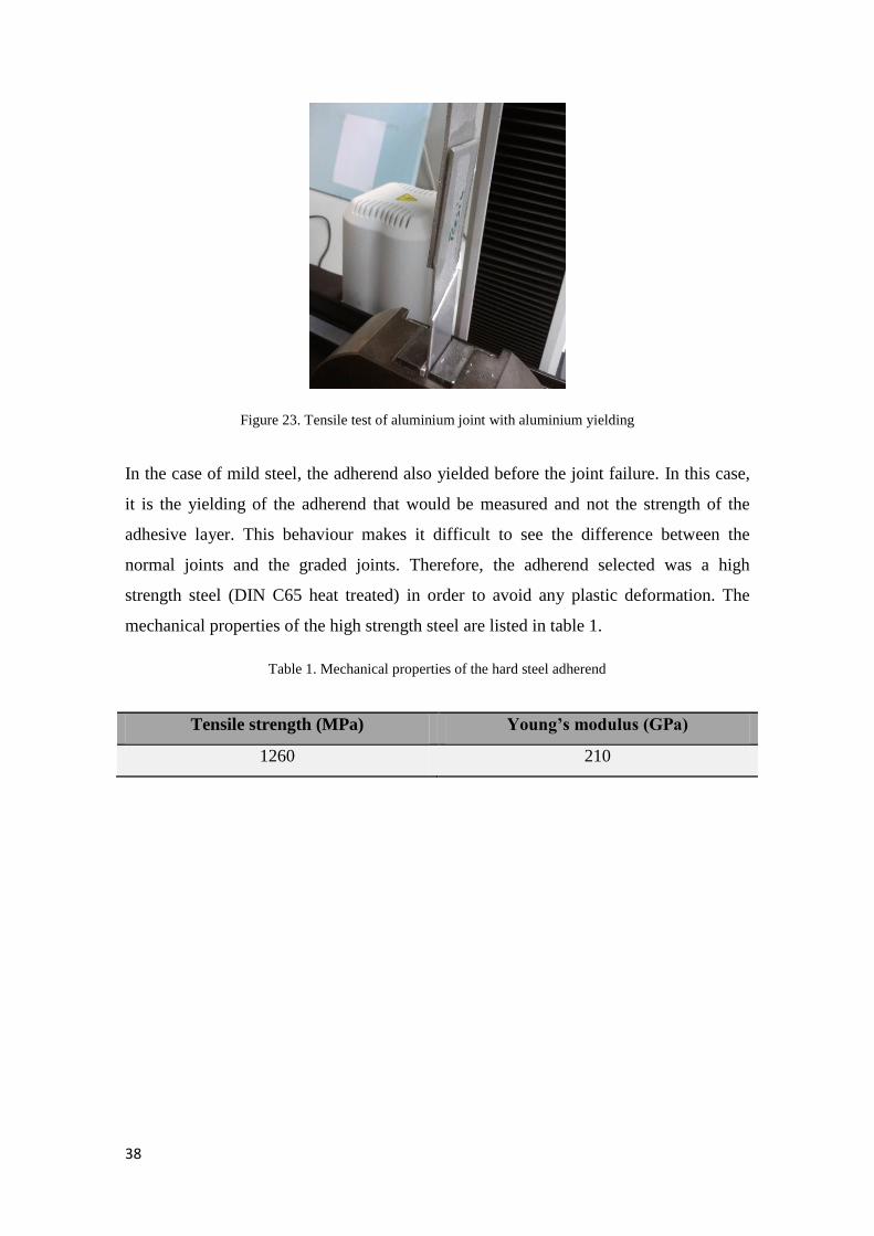
In the case of mild steel, the adherend also yielded before the joint failure. In this case,
it is the yielding of the adherend that would be measured and not the strength of the
adhesive layer. This behaviour makes it difficult to see the difference between the
normal joints and the graded joints. Therefore, the adherend selected was a high
strength steel (DIN C65 heat treated) in order to avoid any plastic deformation. The
mechanical properties of the high strength steel are listed in table 1.
Table 1. Mechanical properties of the hard steel adherend
Tensile strength (MPa) Young’s modulus (GPa)
1260 210
4. RESULTS
39
4.2 Adhesives properties
Having established that the graded cure is not viable, the next step was to characterize
the mechanical properties of the adhesive (Araldite 2011) as a function of the amount of
carbon black nanoparticles. Therefore, bulk specimens were manufactured and tested.
4.2.1 Bulk manufacture method
There are many test methods for the determination of failure strength data. Tests on neat
resin or bulk specimens are the most common to obtain the mechanical properties of
adhesives and predict the failure of adhesives bonds. However, there are several
methods to obtain the bulk specimens. da Silva et al. [71] proposed an effective
manufacture process for bulk specimens as a function of the type of the adhesive.
In the present work, a two component epoxy resin was used and the French standard
NFT 76-142 is the recommended technique. However, the adhesive has to be heated by
microwaves and the commonly used hot plate press can’t be used. Therefore, a similar
process was developed in order to obtain the advantages of the French method.
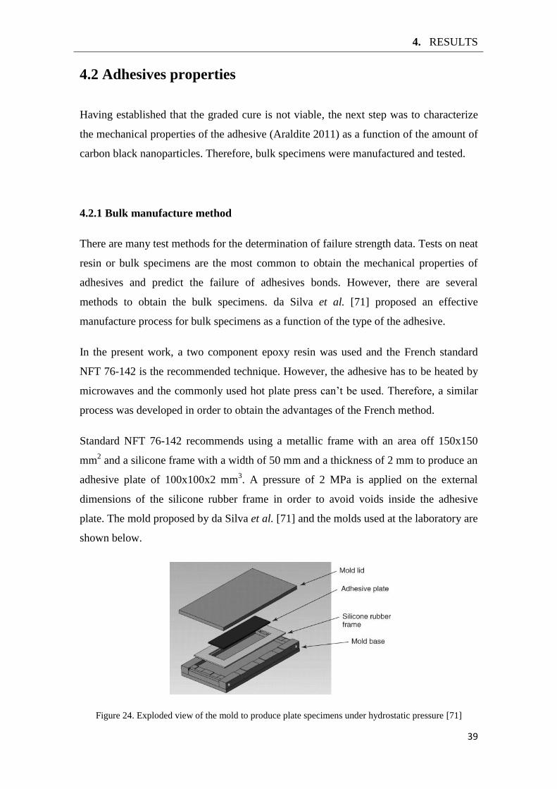
Standard NFT 76-142 recommends using a metallic frame with an area off 150x150
mm2 and a silicone frame with a width of 50 mm and a thickness of 2 mm to produce an
adhesive plate of 100x100x2 mm3. A pressure of 2 MPa is applied on the external
dimensions of the silicone rubber frame in order to avoid voids inside the adhesive
plate. The mold proposed by da Silva et al. [71] and the molds used at the laboratory are
shown below.
Figure 24. Exploded view of the mold to produce plate specimens under hydrostatic pressure [71]
40
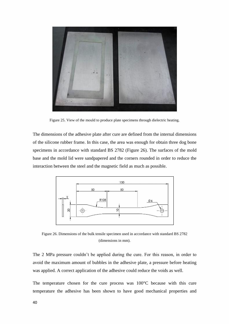
Figure 25. View of the mould to produce plate specimens through dielectric heating.
The dimensions of the adhesive plate after cure are defined from the internal dimensions
of the silicone rubber frame. In this case, the area was enough for obtain three dog bone
specimens in accordance with standard BS 2782 (Figure 26). The surfaces of the mold
base and the mold lid were sandpapered and the corners rounded in order to reduce the
interaction between the steel and the magnetic field as much as possible.
Figure 26. Dimensions of the bulk tensile specimen used in accordance with standard BS 2782
(dimensions in mm).
The 2 MPa pressure couldn’t be applied during the cure. For this reason, in order to
avoid the maximum amount of bubbles in the adhesive plate, a pressure before heating
was applied. A correct application of the adhesive could reduce the voids as well.
The temperature chosen for the cure process was 100°C because with this cure
temperature the adhesive has been shown to have good mechanical properties and
4. RESULTS
41
ductile behaviour (see Figure 19). The supplier recommends to heat 6 min at this
temperature in order to obtain a complete cure.
For microwave cure, the adhesive was heated using 200 W of power (defrost power) in
steps of 2 minutes up to 100°C. After, the temperature was kept during 6 min.
4.2.2 Bulk manufacture
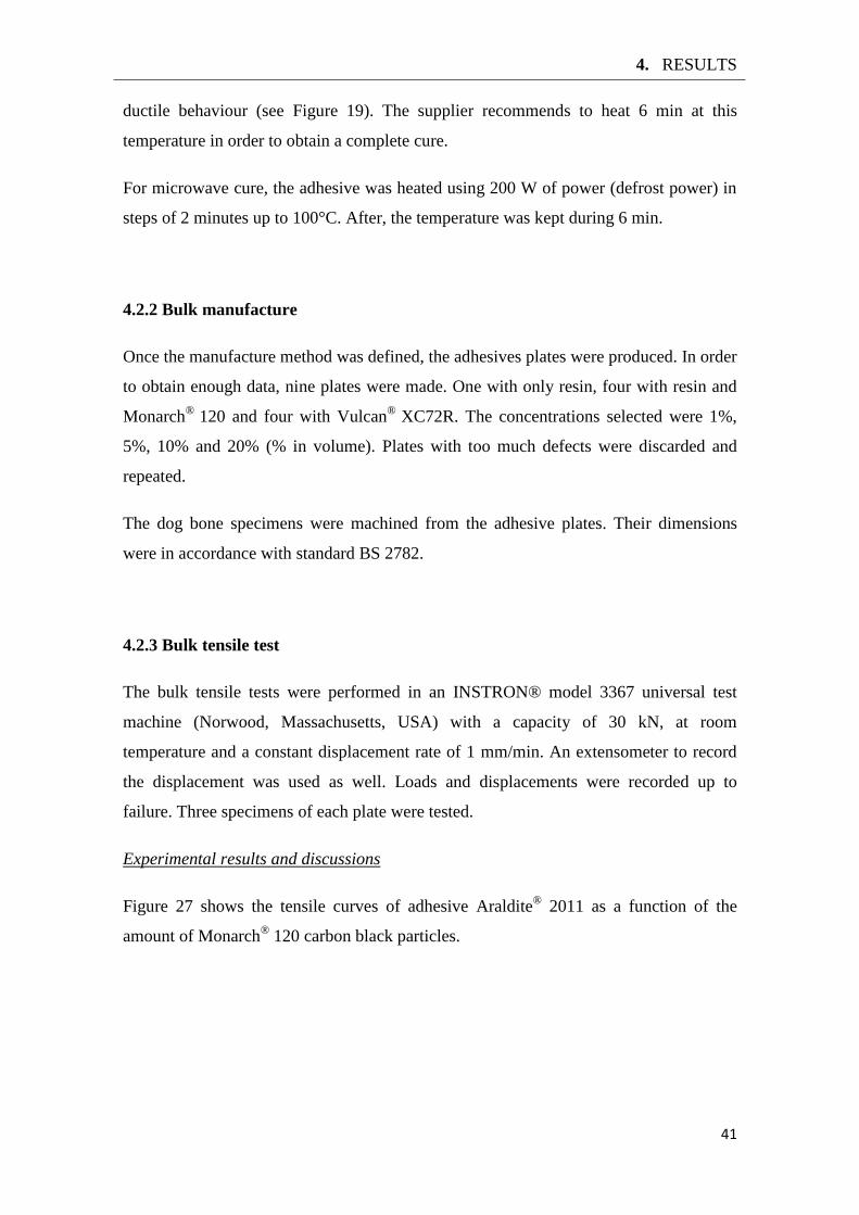
Once the manufacture method was defined, the adhesives plates were produced. In order
to obtain enough data, nine plates were made. One with only resin, four with resin and
Monarch®
120 and four with Vulcan®
XC72R. The concentrations selected were 1%,
5%, 10% and 20% (% in volume). Plates with too much defects were discarded and
repeated.
The dog bone specimens were machined from the adhesive plates. Their dimensions
were in accordance with standard BS 2782.
4.2.3 Bulk tensile test
The bulk tensile tests were performed in an INSTRON® model 3367 universal test
machine (Norwood, Massachusetts, USA) with a capacity of 30 kN, at room
temperature and a constant displacement rate of 1 mm/min. An extensometer to record
the displacement was used as well. Loads and displacements were recorded up to
failure. Three specimens of each plate were tested.
Experimental results and discussions
Figure 27 shows the tensile curves of adhesive Araldite®
2011 as a function of the
amount of Monarch® 120 carbon black particles.
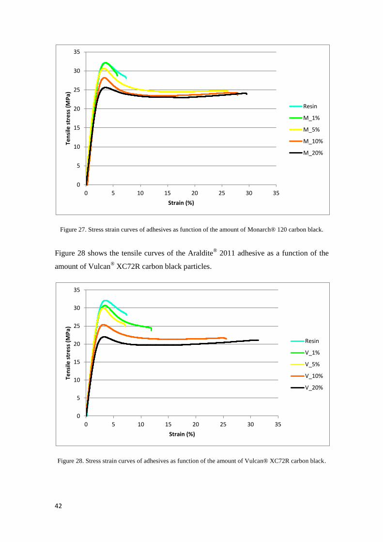
42
Figure 27. Stress strain curves of adhesives as function of the amount of Monarch® 120 carbon black.
Figure 28 shows the tensile curves of the Araldite® 2011 adhesive as a function of the
amount of Vulcan® XC72R carbon black particles.
Figure 28. Stress strain curves of adhesives as function of the amount of Vulcan® XC72R carbon black.
0
5
10
15
20
25
30
35
0 5 10 15 20 25 30 35
Ten
sile
str
ess
(M
Pa)
Strain (%)
Resin
M_1%
M_5%
M_10%
M_20%
0
5
10
15
20
25
30
35
0 5 10 15 20 25 30 35
Ten
sile
str
ess
(M
Pa)
Strain (%)
Resin
V_1%
V_5%
V_10%
V_20%
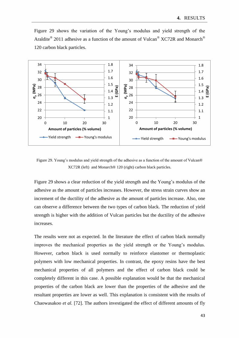
4. RESULTS
43
Figure 29 shows the variation of the Young’s modulus and yield strength of the
Araldite® 2011 adhesive as a function of the amount of Vulcan
® XC72R and Monarch
®
120 carbon black particles.
Figure 29. Young’s modulus and yield strength of the adhesive as a function of the amount of Vulcan®
XC72R (left) and Monarch® 120 (right) carbon black particles.
Figure 29 shows a clear reduction of the yield strength and the Young’s modulus of the
adhesive as the amount of particles increases. However, the stress strain curves show an
increment of the ductility of the adhesive as the amount of particles increase. Also, one
can observe a difference between the two types of carbon black. The reduction of yield
strength is higher with the addition of Vulcan particles but the ductility of the adhesive
increases.
The results were not as expected. In the literature the effect of carbon black normally
improves the mechanical properties as the yield strength or the Young’s modulus.
However, carbon black is used normally to reinforce elastomer or thermoplastic
polymers with low mechanical properties. In contrast, the epoxy resins have the best
mechanical properties of all polymers and the effect of carbon black could be
completely different in this case. A possible explanation would be that the mechanical
properties of the carbon black are lower than the properties of the adhesive and the
resultant properties are lower as well. This explanation is consistent with the results of
Chaowasakoo et al. [72]. The authors investigated the effect of different amounts of fly
1
1.1
1.2
1.3
1.4
1.5
1.6
1.7
1.8
20
22
24
26
28
30
32
34
0 10 20 30
E (G
Pa)
σγ
(M
Pa)
Amount of particles (% volume)
Yield strength Young's modulus
1
1.1
1.2
1.3
1.4
1.5
1.6
1.7
1.8
20
22
24
26
28
30
32
34
0 10 20 30
E (G
Pa)
σγ
(M
Pa)
Amount of particles (% volume)
Yield strength Young's modulus
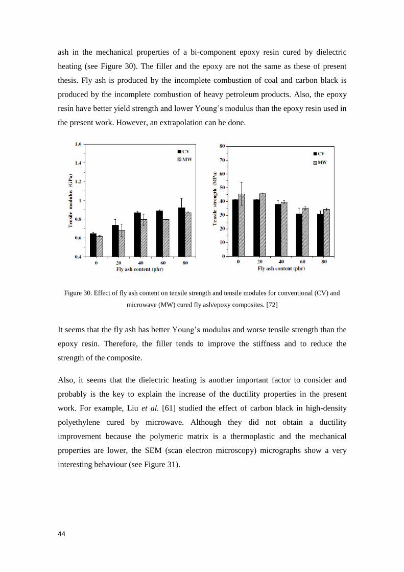
44
ash in the mechanical properties of a bi-component epoxy resin cured by dielectric
heating (see Figure 30). The filler and the epoxy are not the same as these of present
thesis. Fly ash is produced by the incomplete combustion of coal and carbon black is
produced by the incomplete combustion of heavy petroleum products. Also, the epoxy
resin have better yield strength and lower Young’s modulus than the epoxy resin used in
the present work. However, an extrapolation can be done.
Figure 30. Effect of fly ash content on tensile strength and tensile modules for conventional (CV) and
microwave (MW) cured fly ash/epoxy composites. [72]
It seems that the fly ash has better Young’s modulus and worse tensile strength than the
epoxy resin. Therefore, the filler tends to improve the stiffness and to reduce the
strength of the composite.
Also, it seems that the dielectric heating is another important factor to consider and
probably is the key to explain the increase of the ductility properties in the present
work. For example, Liu et al. [61] studied the effect of carbon black in high-density
polyethylene cured by microwave. Although they did not obtain a ductility
improvement because the polymeric matrix is a thermoplastic and the mechanical
properties are lower, the SEM (scan electron microscopy) micrographs show a very
interesting behaviour (see Figure 31).
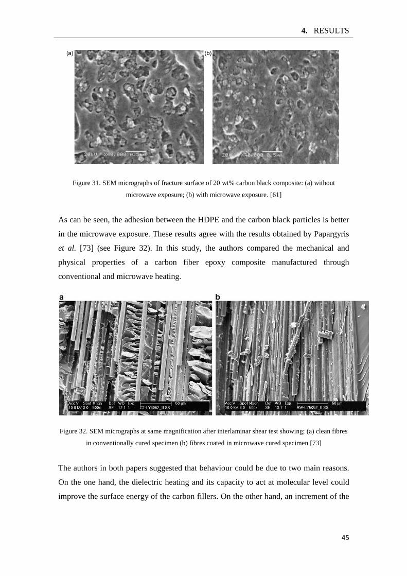
4. RESULTS
45
Figure 31. SEM micrographs of fracture surface of 20 wt% carbon black composite: (a) without
microwave exposure; (b) with microwave exposure. [61]
As can be seen, the adhesion between the HDPE and the carbon black particles is better
in the microwave exposure. These results agree with the results obtained by Papargyris
et al. [73] (see Figure 32). In this study, the authors compared the mechanical and
physical properties of a carbon fiber epoxy composite manufactured through
conventional and microwave heating.
Figure 32. SEM micrographs at same magnification after interlaminar shear test showing; (a) clean fibres
in conventionally cured specimen (b) fibres coated in microwave cured specimen [73]
The authors in both papers suggested that behaviour could be due to two main reasons.
On the one hand, the dielectric heating and its capacity to act at molecular level could
improve the surface energy of the carbon fillers. On the other hand, an increment of the

46
viscosity of the polymer was considered and this could enhance the wetting of the
particles.
Therefore, the Vulcan particles could have worse mechanical properties and better
surface structure than the Monarch particles. However, these are only hypothetical
theories and additional studies should to be done in order to understand this behaviour.
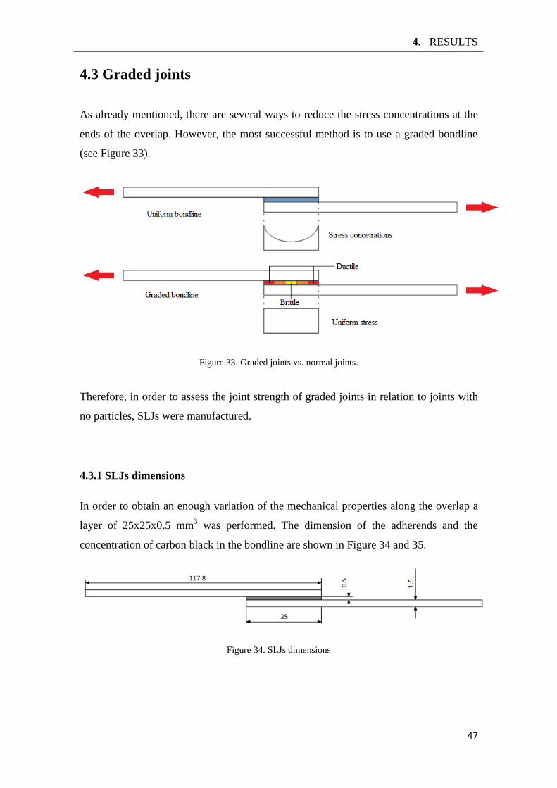
4. RESULTS
47
4.3 Graded joints
As already mentioned, there are several ways to reduce the stress concentrations at the
ends of the overlap. However, the most successful method is to use a graded bondline
(see Figure 33).
Figure 33. Graded joints vs. normal joints.
Therefore, in order to assess the joint strength of graded joints in relation to joints with
no particles, SLJs were manufactured.
4.3.1 SLJs dimensions
In order to obtain an enough variation of the mechanical properties along the overlap a
layer of 25x25x0.5 mm3 was performed. The dimension of the adherends and the
concentration of carbon black in the bondline are shown in Figure 34 and 35.
Figure 34. SLJs dimensions
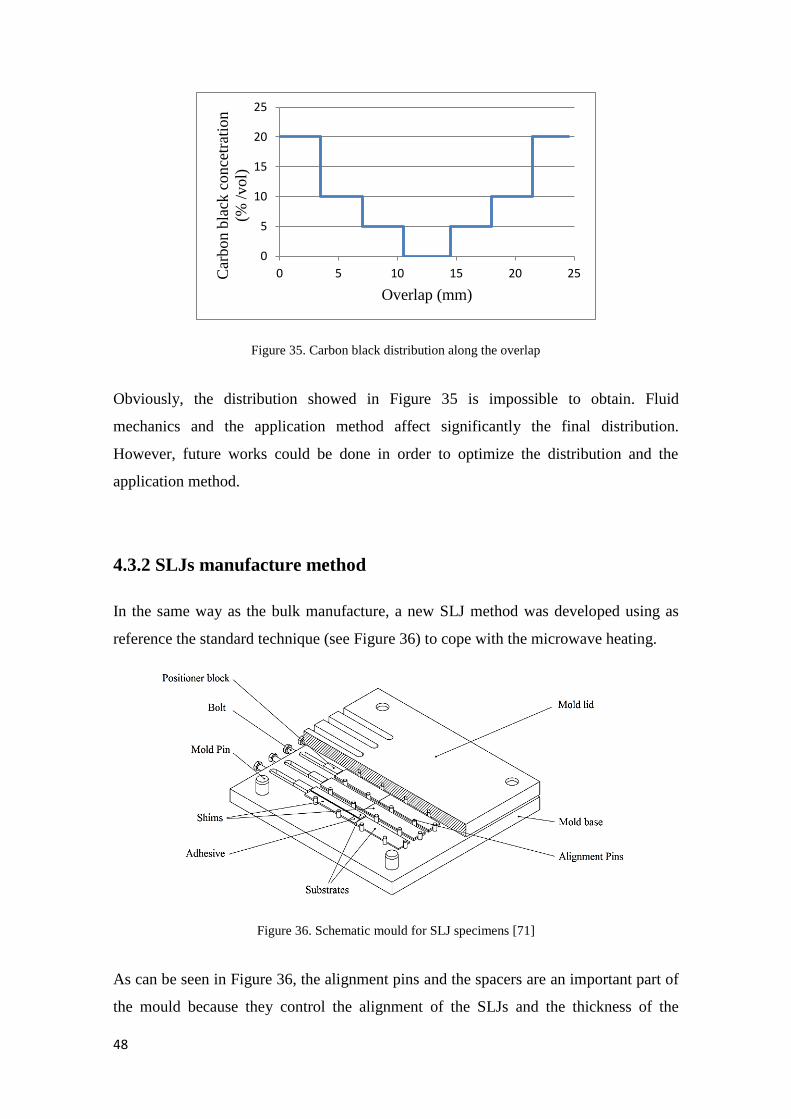
48
Figure 35. Carbon black distribution along the overlap
Obviously, the distribution showed in Figure 35 is impossible to obtain. Fluid
mechanics and the application method affect significantly the final distribution.
However, future works could be done in order to optimize the distribution and the
application method.
4.3.2 SLJs manufacture method
In the same way as the bulk manufacture, a new SLJ method was developed using as
reference the standard technique (see Figure 36) to cope with the microwave heating.
Figure 36. Schematic mould for SLJ specimens [71]
As can be seen in Figure 36, the alignment pins and the spacers are an important part of
the mould because they control the alignment of the SLJs and the thickness of the
0
5
10
15
20
25
0 5 10 15 20 25 Car
bo
n b
lack
co
nce
trat
ion
(% /
vol)
Overlap (mm)
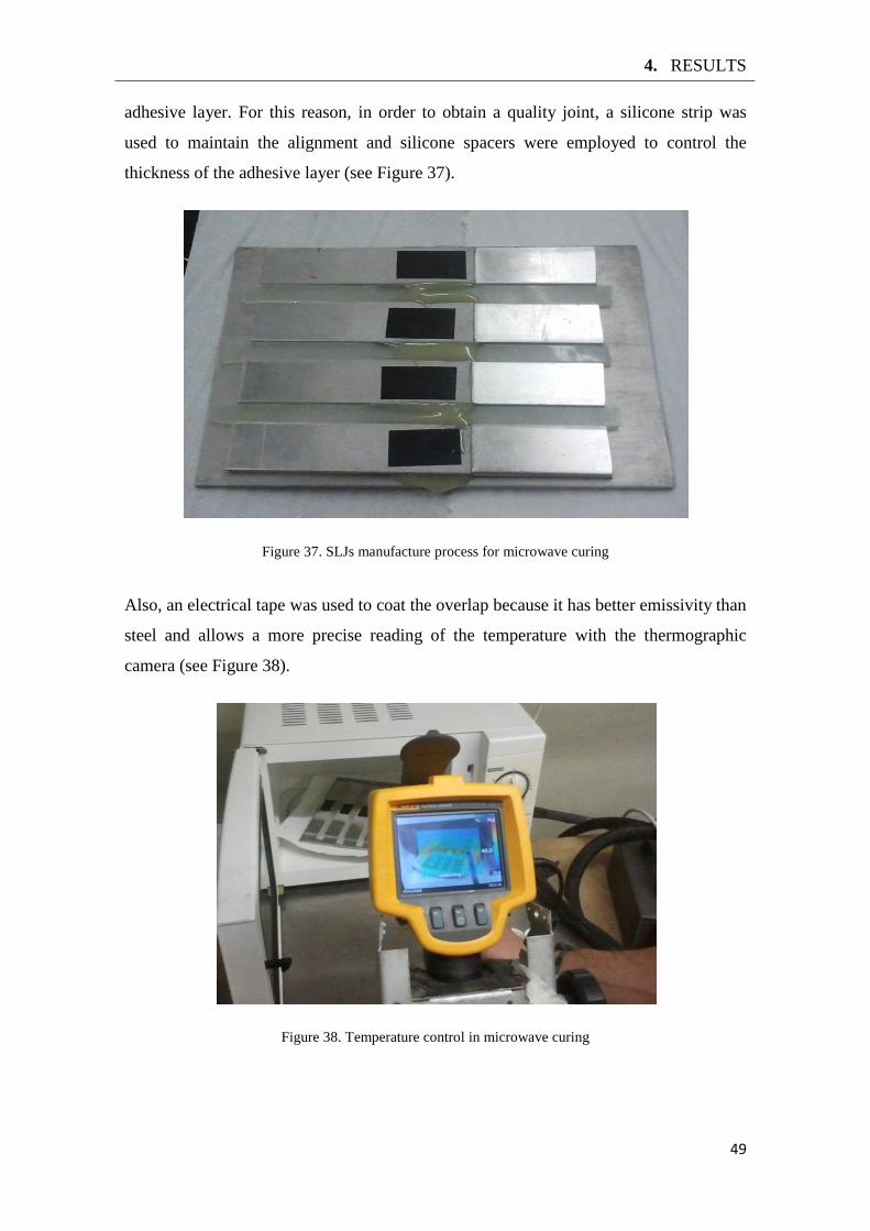
4. RESULTS
49
adhesive layer. For this reason, in order to obtain a quality joint, a silicone strip was
used to maintain the alignment and silicone spacers were employed to control the
thickness of the adhesive layer (see Figure 37).
Figure 37. SLJs manufacture process for microwave curing
Also, an electrical tape was used to coat the overlap because it has better emissivity than
steel and allows a more precise reading of the temperature with the thermographic
camera (see Figure 38).
Figure 38. Temperature control in microwave curing
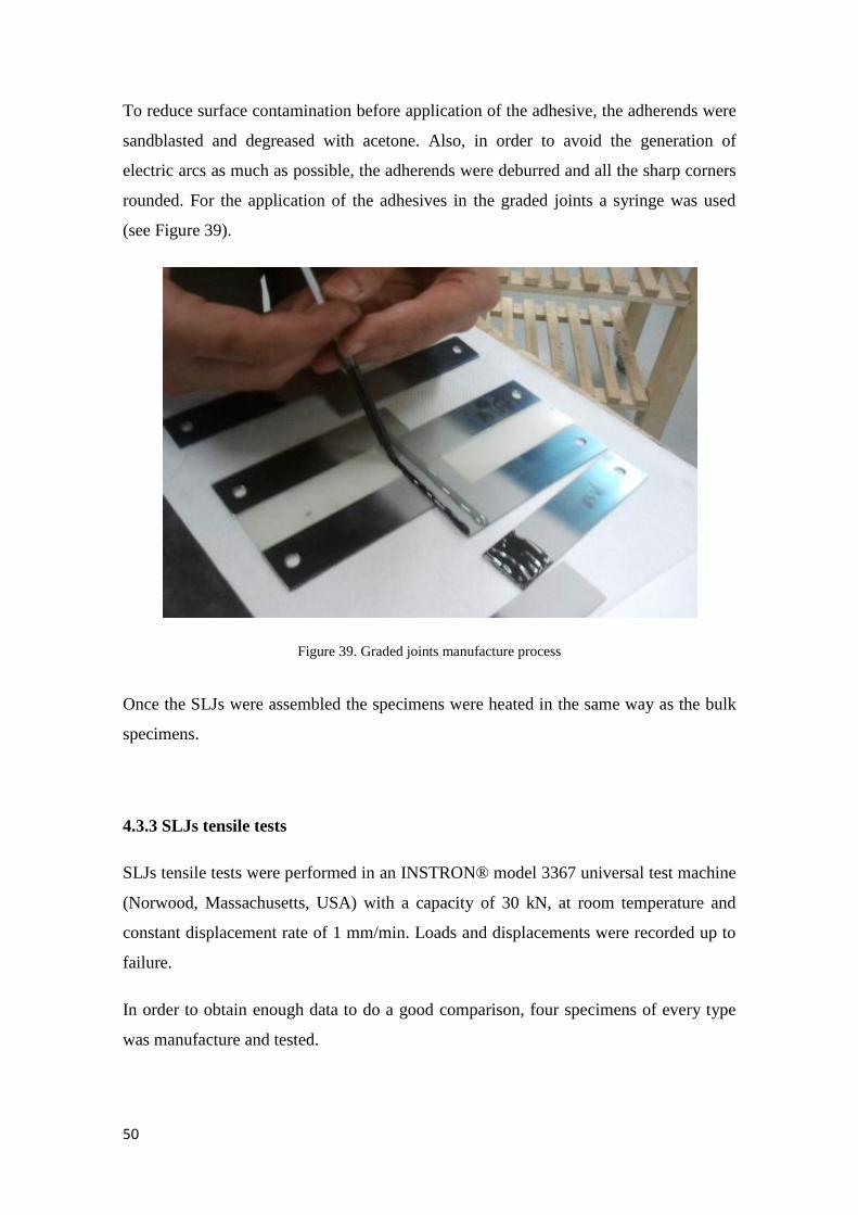
50
To reduce surface contamination before application of the adhesive, the adherends were
sandblasted and degreased with acetone. Also, in order to avoid the generation of
electric arcs as much as possible, the adherends were deburred and all the sharp corners
rounded. For the application of the adhesives in the graded joints a syringe was used
(see Figure 39).
Figure 39. Graded joints manufacture process
Once the SLJs were assembled the specimens were heated in the same way as the bulk
specimens.
4.3.3 SLJs tensile tests
SLJs tensile tests were performed in an INSTRON® model 3367 universal test machine
(Norwood, Massachusetts, USA) with a capacity of 30 kN, at room temperature and
constant displacement rate of 1 mm/min. Loads and displacements were recorded up to
failure.
In order to obtain enough data to do a good comparison, four specimens of every type
was manufacture and tested.
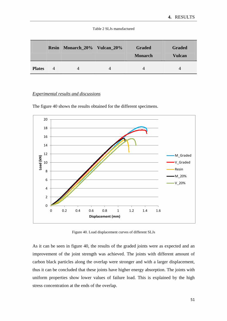
4. RESULTS
51
Table 2 SLJs manufactured
Resin Monarch_20% Vulcan_20% Graded
Monarch
Graded
Vulcan
Plates 4 4 4 4 4
Experimental results and discussions
The figure 40 shows the results obtained for the different specimens.
Figure 40. Load displacement curves of different SLJs
As it can be seen in figure 40, the results of the graded joints were as expected and an
improvement of the joint strength was achieved. The joints with different amount of
carbon black particles along the overlap were stronger and with a larger displacement,
thus it can be concluded that these joints have higher energy absorption. The joints with
uniform properties show lower values of failure load. This is explained by the high
stress concentration at the ends of the overlap.
0
2
4
6
8
10
12
14
16
18
20
0 0.2 0.4 0.6 0.8 1 1.2 1.4 1.6
Load
(kN
)
Displacement (mm)
M_Graded
V_Graded
Resin
M_20%
V_20%
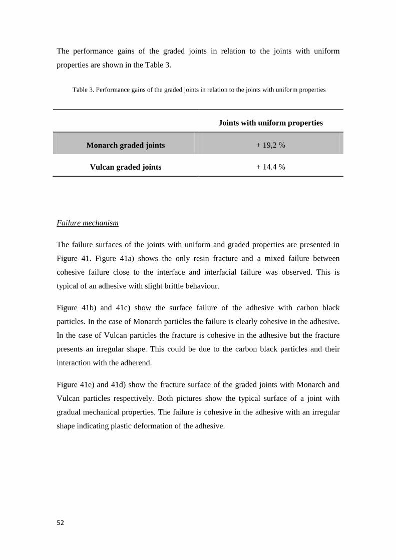
52
The performance gains of the graded joints in relation to the joints with uniform
properties are shown in the Table 3.
Table 3. Performance gains of the graded joints in relation to the joints with uniform properties
Joints with uniform properties
Monarch graded joints + 19,2 %
Vulcan graded joints + 14.4 %
Failure mechanism
The failure surfaces of the joints with uniform and graded properties are presented in
Figure 41. Figure 41a) shows the only resin fracture and a mixed failure between
cohesive failure close to the interface and interfacial failure was observed. This is
typical of an adhesive with slight brittle behaviour.
Figure 41b) and 41c) show the surface failure of the adhesive with carbon black
particles. In the case of Monarch particles the failure is clearly cohesive in the adhesive.
In the case of Vulcan particles the fracture is cohesive in the adhesive but the fracture
presents an irregular shape. This could be due to the carbon black particles and their
interaction with the adherend.
Figure 41e) and 41d) show the fracture surface of the graded joints with Monarch and
Vulcan particles respectively. Both pictures show the typical surface of a joint with
gradual mechanical properties. The failure is cohesive in the adhesive with an irregular
shape indicating plastic deformation of the adhesive.
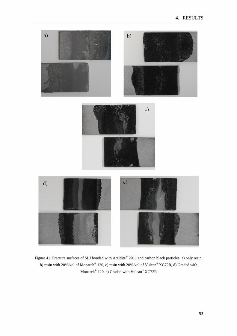
4. RESULTS
53
Figure 41. Fracture surfaces of SLJ bonded with Araldite® 2011 and carbon black particles: a) only resin,
b) resin with 20%/vol of Monarch® 120, c) resin with 20%/vol of Vulcan
® XC72R, d) Graded with
Monarch® 120, e) Graded with Vulcan
® XC72R
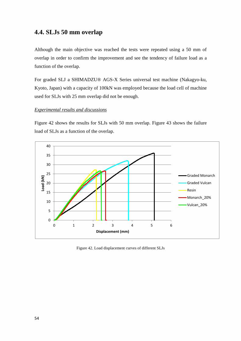
54
4.4. SLJs 50 mm overlap
Although the main objective was reached the tests were repeated using a 50 mm of
overlap in order to confirm the improvement and see the tendency of failure load as a
function of the overlap.
For graded SLJ a SHIMADZU® AGS-X Series universal test machine (Nakagyo-ku,
Kyoto, Japan) with a capacity of 100kN was employed because the load cell of machine
used for SLJs with 25 mm overlap did not be enough.
Experimental results and discussions
Figure 42 shows the results for SLJs with 50 mm overlap. Figure 43 shows the failure
load of SLJs as a function of the overlap.
Figure 42. Load displacement curves of different SLJs
0
5
10
15
20
25
30
35
40
0 1 2 3 4 5 6
Load
(kN
)
Displacement (mm)
Graded Monarch
Graded Vulcan
Resin
Monarch_20%
Vulcan_20%
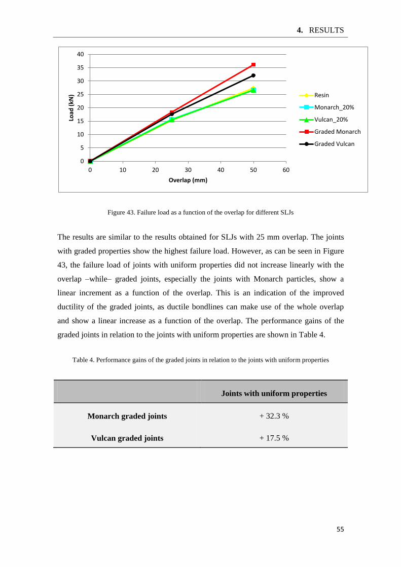
4. RESULTS
55
Figure 43. Failure load as a function of the overlap for different SLJs
The results are similar to the results obtained for SLJs with 25 mm overlap. The joints
with graded properties show the highest failure load. However, as can be seen in Figure
43, the failure load of joints with uniform properties did not increase linearly with the
overlap –while– graded joints, especially the joints with Monarch particles, show a
linear increment as a function of the overlap. This is an indication of the improved
ductility of the graded joints, as ductile bondlines can make use of the whole overlap
and show a linear increase as a function of the overlap. The performance gains of the
graded joints in relation to the joints with uniform properties are shown in Table 4.
Table 4. Performance gains of the graded joints in relation to the joints with uniform properties
Joints with uniform properties
Monarch graded joints + 32.3 %
Vulcan graded joints + 17.5 %
0
5
10
15
20
25
30
35
40
0 10 20 30 40 50 60
Load
(kN
)
Overlap (mm)
Resin
Monarch_20%
Vulcan_20%
Graded Monarch
Graded Vulcan
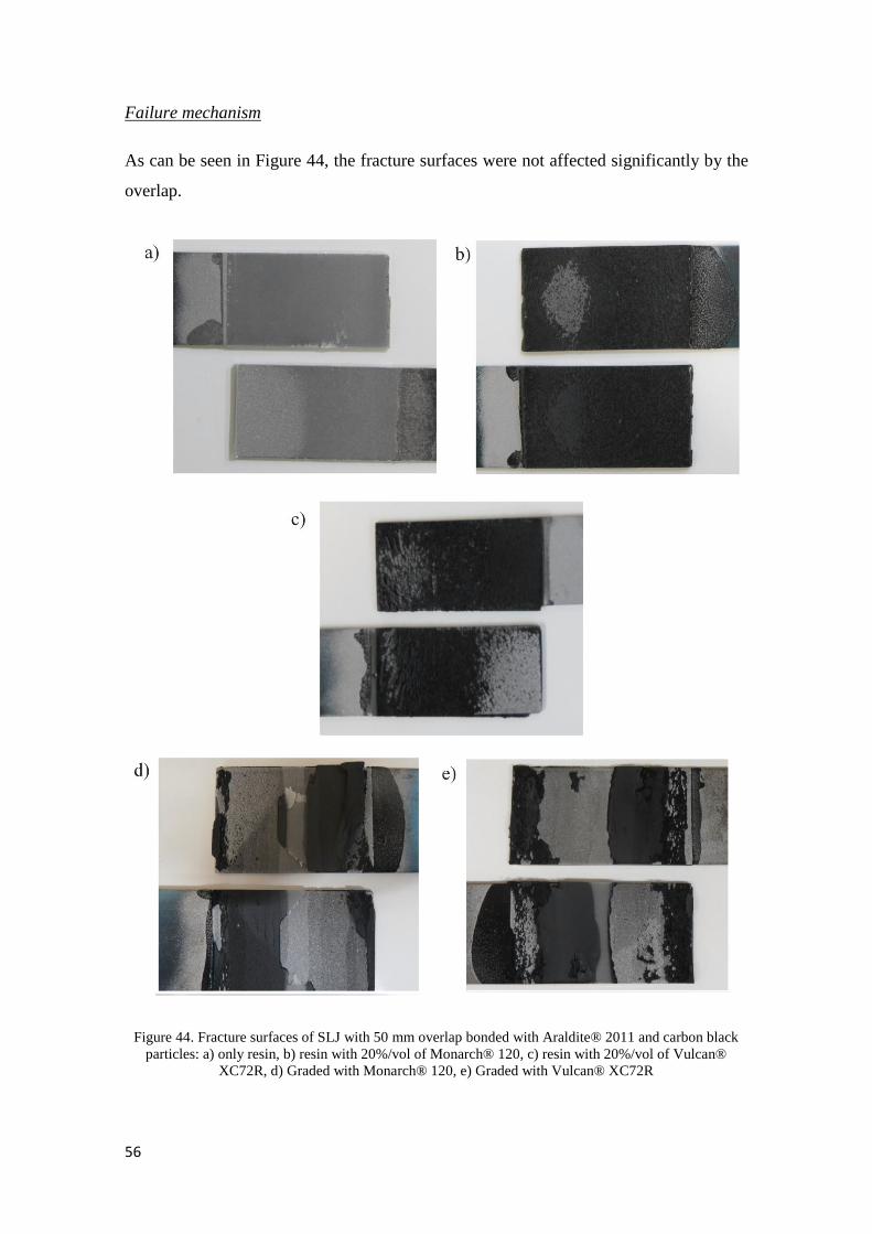
56
Failure mechanism
As can be seen in Figure 44, the fracture surfaces were not affected significantly by the
overlap.
Figure 44. Fracture surfaces of SLJ with 50 mm overlap bonded with Araldite® 2011 and carbon black
particles: a) only resin, b) resin with 20%/vol of Monarch® 120, c) resin with 20%/vol of Vulcan®
XC72R, d) Graded with Monarch® 120, e) Graded with Vulcan® XC72R
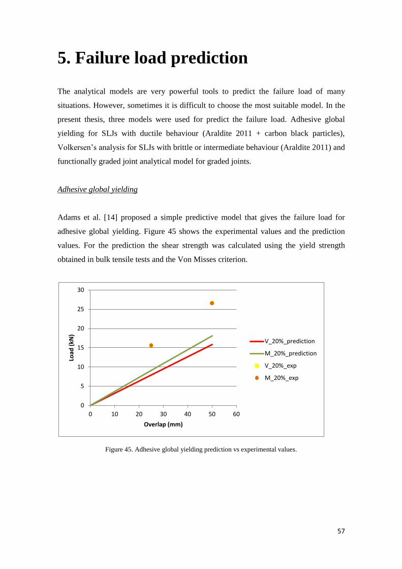
57
5. Failure load prediction
The analytical models are very powerful tools to predict the failure load of many
situations. However, sometimes it is difficult to choose the most suitable model. In the
present thesis, three models were used for predict the failure load. Adhesive global
yielding for SLJs with ductile behaviour (Araldite 2011 + carbon black particles),
Volkersen’s analysis for SLJs with brittle or intermediate behaviour (Araldite 2011) and
functionally graded joint analytical model for graded joints.
Adhesive global yielding
Adams et al. [14] proposed a simple predictive model that gives the failure load for
adhesive global yielding. Figure 45 shows the experimental values and the prediction
values. For the prediction the shear strength was calculated using the yield strength
obtained in bulk tensile tests and the Von Misses criterion.
Figure 45. Adhesive global yielding prediction vs experimental values.
0
5
10
15
20
25
30
0 10 20 30 40 50 60
Load
(kN
)
Overlap (mm)
V_20%_prediction
M_20%_prediction
V_20%_exp
M_20%_exp
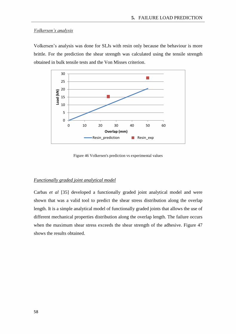
5. FAILURE LOAD PREDICTION
58
Volkersen’s analysis
Volkersen’s analysis was done for SLJs with resin only because the behaviour is more
brittle. For the prediction the shear strength was calculated using the tensile strength
obtained in bulk tensile tests and the Von Misses criterion.
Figure 46 Volkersen's prediction vs experimental values
Functionally graded joint analytical model
Carbas et al [35] developed a functionally graded joint analytical model and were
shown that was a valid tool to predict the shear stress distribution along the overlap
length. It is a simple analytical model of functionally graded joints that allows the use of
different mechanical properties distribution along the overlap length. The failure occurs
when the maximum shear stress exceeds the shear strength of the adhesive. Figure 47
shows the results obtained.
0
5
10
15
20
25
30
0 10 20 30 40 50 60
Load
(kN
)
Overlap (mm)
Resin_prediction Resin_exp
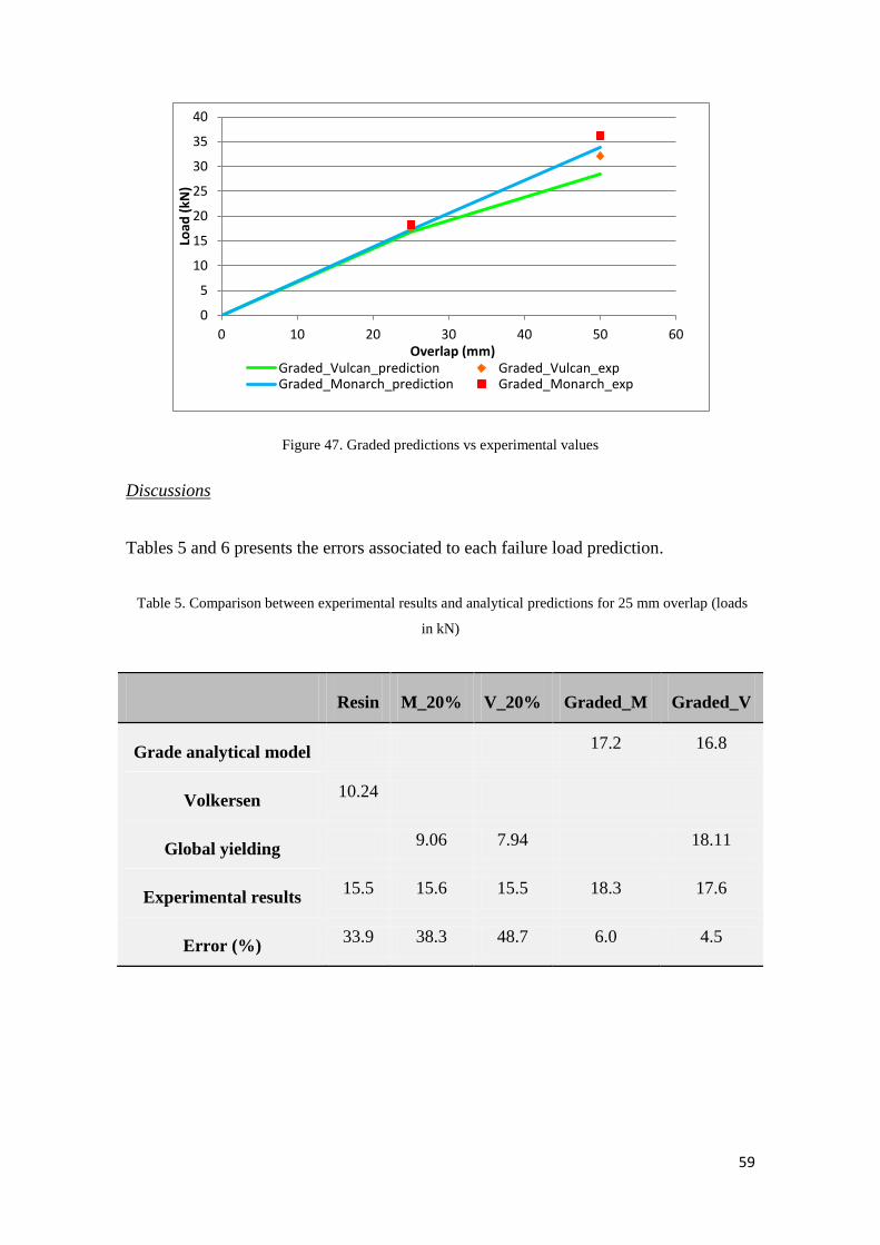
59
Figure 47. Graded predictions vs experimental values
Discussions
Tables 5 and 6 presents the errors associated to each failure load prediction.
Table 5. Comparison between experimental results and analytical predictions for 25 mm overlap (loads
in kN)
Resin M_20% V_20% Graded_M Graded_V
Grade analytical model 17.2 16.8
Volkersen 10.24
Global yielding 9.06 7.94 18.11
Experimental results 15.5 15.6 15.5 18.3 17.6
Error (%) 33.9 38.3 48.7 6.0 4.5
0
5
10
15
20
25
30
35
40
0 10 20 30 40 50 60
Load
(kN
)
Overlap (mm) Graded_Vulcan_prediction Graded_Vulcan_exp Graded_Monarch_prediction Graded_Monarch_exp
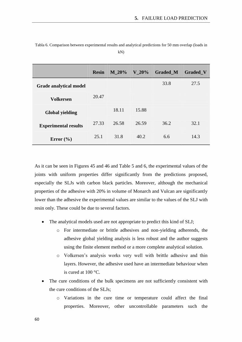
5. FAILURE LOAD PREDICTION
60
Tabla 6. Comparison between experimental results and analytical predictions for 50 mm overlap (loads in
kN)
Resin M_20% V_20% Graded_M Graded_V
Grade analytical model 33.8 27.5
Volkersen 20.47
Global yielding 18.11 15.88
Experimental results 27.33 26.58 26.59 36.2 32.1
Error (%) 25.1 31.8 40.2 6.6 14.3
As it can be seen in Figures 45 and 46 and Table 5 and 6, the experimental values of the
joints with uniform properties differ significantly from the predictions proposed,
especially the SLJs with carbon black particles. Moreover, although the mechanical
properties of the adhesive with 20% in volume of Monarch and Vulcan are significantly
lower than the adhesive the experimental values are similar to the values of the SLJ with
resin only. These could be due to several factors.
The analytical models used are not appropriate to predict this kind of SLJ;
o For intermediate or brittle adhesives and non-yielding adherends, the
adhesive global yielding analysis is less robust and the author suggests
using the finite element method or a more complete analytical solution.
o Volkersen’s analysis works very well with brittle adhesive and thin
layers. However, the adhesive used have an intermediate behaviour when
is cured at 100 °C.
The cure conditions of the bulk specimens are not sufficiently consistent with
the cure conditions of the SLJs;
o Variations in the cure time or temperature could affect the final
properties. Moreover, other uncontrollable parameters such the
61
dispersion of carbon black or ambient conditions could affect the
properties as well.
The defects in the bulk specimens are not negligible;
o The presence of voids was higher in the bulk specimens than the SLJs.
Therefore, the mechanical properties obtained for the bulk specimens
could be lower than they really are.
The dielectric heating affects the adhesion between the adherend and the
adhesive.
o As can be seen in previous sections, the dielectric heating could affect
the viscosity of the adhesive during the cure. This leads to better wetting
of the adherends and, therefore, the joint strength could be higher.
The interaction between the dielectric heating, adherends, carbon black particles
and adhesive affect the adhesion as well.
Several hypotheses have been proposed. However, a more work is necessary in order to
understand this behaviour.
For graded joints Figure 47 and Tables 5 and 6 that the model developed by Carbas et al
[35] gives accurate predictions for the failure load of graded joints. However, it seems
that the error tend to increase with the overlap, specially for Vulcan particles.

63
6. Conclusions
The aim of this research was to develop a technique to obtain a graded joint through
dielectric heating. In order to achieve this objective two methods were proposed and
studied.
The first consisted in obtaining a graded cure along the overlap using microwave
absorbing particles (carbon black) and a structural adhesive with large variation in
properties as function of the cure temperature. However, the viability of this method
was studied and different barriers were found.
The use of adherends with low thermal conductivity generated overheating of
the adhesive due to the uniformity issues related with the magnetic field;
The use of adherends with high thermal conductivity prevented the overheating.
However, the rest of the adhesive was uniformly heated by conduction and the
graded cure could not be achieved.
The possible solution could be to use a cooler system. However, due to the
enclosed structure of the microwave oven and the interaction of the typical
cooler systems with the magnetic field the idea was discarded.
The second method proposed consisted in obtaining graded mechanical properties using
reinforcement fillers. The carbon particles were used to vary the ductility of the
adhesive. Using this method graded joints were manufactured and an improvement of
the joint strength was achieved. The following steps were followed.
The characterization of the adhesive properties as a function of the carbon black
was made and an improvement of the ductility was obtained;
o The interaction between adhesive/carbon black/dielectric heating were
considered as the key to explain this behaviour.
The graded SLJs were manufactured using a high local concentration of carbon
black. This made the adhesive more ductile at the ends of the overlap and a
higher joint strength was obtained.
Two kinds of carbon black particles were tested (Monarch®
120 and Vulcan® XC872R)
and the SLJs with Monarch particles showed the best result.


65
7. Future Work
During the course of this thesis some questions have been raised and were not answered
yet. These could lead to new and possibly important investigation works. The most
important issues are the following points:
Study the interaction between the carbon black, the adhesive and the
microwave;
Study the effect of carbon black in the adhesive properties through
conventional heating;
To develop new microwave devices and ways to control the dielectric
heating;
To develop better methods to manufacture the bulk specimens and the
SLJs when cured by dielectric heating;
To develop a way to obtain a graded cure by dielectric heating.
To mix the particles in the adhesive along the overlap in a more refined
way.

67
References
[1] W. Brockmann, P. Geiss, J. Klingen, and B. Schroder, Adhesive Bonding - Materials,
Aplications and Technology, Weinheim: Wiley-VCH, 2009.
[2] A. Kinloch, Adhesion and Adhesives : Science and Technology, London: Chapman and Hall,
1987.
[3] L. F. M. da Silva, A. Ochsner, R. D. Adams, Handbook of Adhesion Technology, vol. 1,
Heidelberg: Springer, 2011.
[4] D. Kopeliovich, “SubsTech substance&technologies,” Creativecommons, 2 june 2012.
[Online]. Available: http://www.substech.com/dokuwiki/doku.php?id=adhesive_joints.
[Accessed May 2014].
[5] L.F.M. da Silva, Paulo J.C. das Neves, R.D. Adams, J.K. Spelt, “Analytical models of
adhesively bonded joints - Part I: Literature survey,” Int. J. Adhes, vol. 29, p. 319–330,
2009.
[6] R. G. H. Davies, Analysis of the influence of temperature on the performance of adhesively
bonded single lap joints, PhD thesis, South Bank University, 2000.
[7] M.Y. Tsai, J. Morton, “The effect of a spew fillet on adhesive stresss distributions in
laminated composite single lap joints,” Compos. Struct, vol. 32, pp. 123-131, 1995.
[8] T.P. Lang, P.K. Mallick, “Effect of spew geometry on stresses in single lap adhesive joints,”
Int. J. Adhes, vol. 18, pp. 167-177, 1998.
[9] Y. Frostig, O.T. Thomsen, F. Mortensen, “Analysis of adhesive-bonded joints, square-end,
and spew-fillet - high-order theory approach,” J. Eng. Mech, vol. 125, pp. 1298-1307,
1999.
[10] G. Belingardi, L. Goglio, A. Tarditi, “Investigating the effect of spew and chamfer size on
the stresses in metal/plastics adhesive joints,” Int. J. Adhes., vol. 22, pp. 273-282, 2002.
[11] L.F.M da Silva, R.D. Adams, “Adhesive joints at high and low temperatures using similar
and dissimilar adherends and dual adhesives,” Int. J. Adhes., vol. 22, pp. 216-226, 2007.
[12] L.F.M da Silva, R.D Adams, “Joint strength predictions for adhesive joints to be used over a
wide temperature range,” Int. J. Adhes, vol. 27, pp. 362-379, 2007.
68
[13] R.D. Adams, J.A. Harris, “The influence of local geometry on the strength of adhesive
joints,” Int. J. Adhes., vol. 7, pp. 69-80, 1987.
[14] R.D. Adams, J. Comyn, W.C. Wake, Strucutural adhesive joints in engineering, second ed.,
London: Chapman & Hall, 1997.
[15] X. Zhao, R.D Adams, L.F.M. da Silva, “Single lap joints with rounded adherend corners:
Experimental results and strength predictions,” J. Adhes. Sci. Technol, vol. 25, pp. 837-856,
2011.
[16] X. Zhao, R.D Adams, L.F.M. da Silva, “Single lap joints with rounded adherend corners:
Stress and strain analysis,” J. Adhes. Scj. Technol, vol. 25, pp. 819-836, 2011.
[17] A.R. Rispler, L.Tong, G.P. Steven, M.R. Wisnom, “Shape optimisation of adhesive fillets,”
Int. J. Adhes, vol. 20, pp. 221-231, 2000.
[18] L.F.M. da Silva, R.D. Adams, “Techniques to reduce the peel stresses in adhesive joints
with composites,” Int. J. Adhes, vol. 27, pp. 227-235, 2007.
[19] E.A.S. Marques, L.F.M. da Silva, “Joint strength optimization of adhesively bonded
patches,” J. Adhes, vol. 84, pp. 915-934, 2008.
[20] C. Raphael, “Variable-adhesive bonded joints,” Appl. Polym. Symp., vol. 3, pp. 99-108,
1966.
[21] I. Pires, L. Quintino, J.F. Durodola, A. Beevers, “Performance of bi-adhesive bonded
aluminium lap joints,” Int. J. Adhes, vol. 23, pp. 215-223, 2003.
[22] E.A.S. Marques, D.N.M. Magalhaes, L.F.M. da Silva, “Experimental study of silicone-epoxy
dual adhesive joints for high temperature aerospace applications,” Mater.wiss.
Werkst.tech, vol. 42, pp. 471-477, 2011.
[23] P.J.C das Neves. L.F.M. da Silva, R.D. Adams, “Analysis of mixed adhesive bonded joints
part I: Theoretetical formulation,” J. Adhes. Sci. Technol, vol. 23, pp. 1-34, 2009.
[24] P.J.C das Neves. L.F.M. da Silva, R.D. Adams, “Analysis of mixed adhesive bonded joints
part II: Parametric study,” J. Adhes. Sci. Technol, vol. 23, pp. 35-61, 2009.
[25] L.F.M. da Silva, M.J.C.Q. Lopes, “Joint strength optimization by the mixed-adhesive
technique,” Int. J. Adhes, vol. 29, pp. 329-336, 2009.
[26] M.D. Fitton, J.G. Broughton, “Variable modulus adhesives: and approach to optimised
joint performance,” Int. J. Adhes, vol. 25, pp. 215-223, 2005.
[27] V.K. Ganesh, T.S. Choo, Modulus graded composite adherends for single-lap bonded
joints, J.Compos. Mater., vol. 36, pp. 1757-1767, 2002.
69
[28] J.N. Boss, V.K. Ganesh, C.T. Lim, “Modulus grading versus geometrical grading of
composite adherends in single-lap bonded joints,” Compos. Struct, vol. 36, pp. 113-121,
2003.
[29] M.K. Apalak, R. Gunes, “Elastic flexural behaviour of an adhesively bonded single lap joint
with functionally graded adherends,” Mater. Des, vol. 28, pp. 1597-1617, 2007.
[30] E. Sancaktar, S.Kumar, “Selective use of rubber toughening to optimize lap-joint strength,”
J. Adhes. Sci. Technol, vol. 14, pp. 1265-1296, 2000.
[31] S.E. Stapleton, A.M. Waas, S.M. Arnold, “Functionally graded adhesives for composite
joints,” Int. J. Adhes, vol. 35, pp. 36-49, 2012.
[32] R.J.C. Carbas, E.A.S. Marques, L.F.M. da Silva, A. M.Lopes, “Effect of cure temperature on
the glass transition temperature and mechanical properties of epoxy adhesives,” Int. J.
Adhes, vol. 90, pp. 104-119, 2014.
[33] R.J.C. Carbas, L.F.M.daSilva, G.W.Critchlowc, “Adhesively bonded functionally graded
joints by induction heating,” Int. J. Adhes, vol. 48, pp. 110-118, 2014.
[34] O. Volkersen, Die nietkraftverteilung in zugbeansprutchten Nietverbindungen mit
konstanten aschenquerschnitten, Luftfahrtforschung, 1938.
[35] R.J.C. Carbas, L.F.M.daSilva, M.L. Madureira, G.W.Critchlowc, “Modelling of functionally
graded adhesive joints,” Int. J. Adhes, vol. 90, pp.698-716, 2014.
[36] E.T. Thostenson, T.W. Chou, “Microwave processing: fundamentals and applications,”
Composites, Part A, vol. 30, pp. 1055-1071, 1999.
[37] J. Mijovic and J. Wijaya, “Review of Polymers and Composites by Microwave Energy,”
Polymer Composites,vol. 11, pp. 184-191, 1990.
[38] T. Wang and J. Liu, “A Review of Microwave Curing of Polymeric Materials,” Journal of
Electronics Manufacturing, vol. 10, pp. 181-189, 2000.
[39] S. Allen, Dielectric Techniques: Principles and Practice Vol.1, 1998.
[40] M. Chen, E.J. Siochi, T.C. Ward, J.E. Mc. Grath, “Basic ideas of microwave processing of
polymers,” Polymer Engineering and Science, vol. 33, pp. 1092-1109, 1993.
[41] Mijovic J, Wijaya J., “Review of cure of polymers and composites by microwave energy,”
Polymer Composites, vol. 11, pp. 184-191, 1990.
[42] R. V. Tanikella, S. A. Bidstrup-Allen, and P. Kohl, “Novel Low-Temperature Processing of
Polymer Dielectrics on Organic Substrates by Variable Frequency Microwave Processing,”
8th International Symposium on Advanced Packaging Materials, pp. 254-259, 2002.
70
[43] Marand E, Baker HR, Graybeal JD, “Comparison of reaction mechanisms of epoxy resins
undergoing thermal and microwave cure from insitu measurements of microwave
dielectric properties and infrared spectroscopy,” Macromolecules, vol. 25, pp. 2243-2252,
1992.
[44] J. Wei, M.C. Hawley, J.D. Delong, “Comparison of microwave and thermal cure of epoxy
resins,” Polymer Engineering and Science, vol.33, pp. 1132-1140, 1993.
[45] C. Jordan, J. Galy, J.P. Pascault, “Comparison of microwave and thermal cure of an
epoxy/amine matrix,” Polymer Engineering and Science, vol. 35, pp. 233-239, 1995.
[46] Liming Zong, Leo C. Kempel, Martin C. Hawley, “Dielectric studies of three epoxy resin
systems during microwave cure,” Polymer, vol. 46, pp. 2638-2645, 2005.
[47] J. Mijovic, W.V. Corso, L. Nicolais, G. d’Ambrosio, “In-situ real-time study of crosslinking
kinetics in thermal and microwave fields,” Polymers for Advanced Technologies, vol.9, pp.
231-243, 1998.
[48] J. Mijovic, J. Wijaya, “Comparative calorimetric study of epoxy cure by microwave vs.
thermal energy,” Macromolecules, vol. 23, pp. 3671-3674, 1990.
[49] S.M. Singer, J. Jow, J.D. Delong, M.C. Hawley, “Effects of processing on tensile properties
of an epoxy/amine matrix: continuous electromagnetic and/or thermal curing,” SAMPE
Quarterly, vol. 20, pp. 14-18, 1989.
[50] S.L. Bai, V. Djafari, M. Andreani, D. Francois, “Comparative study of the mechanical
behavior of an epoxy resin cured by microwaves with one cured thermally,” European
Polymer Journal, vol. 31, pp. 875-884, 1995.
[51] B. Geisler, B. Adams, and I. Ahmad, “Advanced Process Finds Optoelectronic
Applications,” Advanced Packaging, 2002.
[52] Sandhya Rao, “Cure studies on bifunctional epoxy matrices using a domestic microwave
oven,” Polymer Testing, vol. 27, pp. 645-652, 2008.
[53] Ayodele Olofinjana, Prasad K.D.V. Yarlagadda, Adekunle Oloyede, “Microwave processing
of adhesive joints using a temperature feedback system,” International Journal of
Machine Tools & Manufacture, vol. 41, pp. 209-225, 2001.
[54] Lambda, System and apparatus for reducing arcing and localized heating during
microwave processing, L. T. Corp, 1998.
[55] Ravindra V. Tanikella, Sue A. Bidstrup Allen, and Paul A. Kohl, Novel Low-Temperature
Processing of Polymer Dielectrics on Organic Substrates by Variable Frequency Microwave
Processing, Atlanta: 8th International Symposium on Advanced Packaging Materials.
71
[56] Seymour, Raymond Benedict; Deaning, Rudolph D, History of Polymeric Composites, VSP,
1987.
[57] T.Vilgis, G.Heinrich and M.Klüppel, Reinforcement of polymer nano-coomposites: Theory,
Experiments and Applications, New York: Cambridge University Press, 2009.
[58] C. Corporation, “Cabot,” Cabot Corporation, 2014. [Online]. Available: http://www.cabot-
corp.com/. [Accessed 2014].
[59] Xiangxuan Liu, Zeyang Zhang, Youpeng Wu, “Absorption properties of carbon black/silicon
carbide microwave absorbers,” Composites: Part B, vol. 42, pp. 326-329, 2011.
[60] K.H. Wu, T.H. Ting, G.P. Wang, W.D. Ho, C.C. Shih, “Effect of carbon black content on
electrical and microwave absorbing properties of polyaniline/carbon black
nanocomposites,” Polymer Degradation and Stability, vol. 93, pp. 483-488, 2008.
[61] Fanghui Liu, Xinyuan Qian, Xian Wu, Chao Guo, Yanwei Lei, Jie Zhang, “The response of
carbon black filled high-density polyethylene,” Journal of Materials Processing
Technology,vol. 210, pp. 1991-1996, 2010.
[62] L. A. Fejgin, Structure analysis by small-angle X-ray and neutron scattering, New york:
Plenum, 1987.
[63] O. Glatter, O. Kratky, Small Angle X-ray Scattering, Academic press, 1982.
[64] S. Brunauer, P. H. Emmett and E. Teller, “Adsorption of gases in multimolecular layers,”
Journal of the American Chemical Society, vol. 60, p. 309–319, 1938.
[65] A. Schröder, M. Klüppel, R.H. Schuster, J. Heidberg, “Surface energy distribution of carbon
black measured by static gas adsorption,” Carbon, vol. 40, pp. 207-210, 2002.
[66] J.B. Donnet, E. Custodéro, T.K. Wang, G. Hennebert, “Energy site distribution of carbon
black surfaces by inverse gas chromatography at finite concentration conditions,” Carbon,
vol. 40, pp. 163-167, 2002.
[67] Eugene Papirer, Eric Brendle, Fabien Ozil, Henri Balard, “Comparison of the surface
properties of graphite, carbon black and fullerene samples, measured by inverse gas
chromatography,” Carbon, vol. 37, pp. 1265-1274, 1999.
[68] S.M. Senthil Kumar, Jaime Soler Herrero, Silvia Irusta, Keith Scott, “The effect of
pretreatment of Vulcan XC-72R carbon on morphology and electrochemical oxygen
reduction kinetics of supported Pd nano-particle in acidic electrolyte,” Journal of
Electroanalytical Chemistry, vol. 647, pp. 211-221, 2010.
[69] M. Gupta, E. Wong Wai Leong, Microwaves and Metals, Wiley, 2008.
72
[70] R. S. Netto, “Fisicanet,” Fisicanet, 2014. [Online]. Available:
http://www.fisicanet.com.ar/fisica/termodinamica/tb03_conductividad.php. [Accessed
2014].
[71] L.F.M. da Silva, D.A. Dillard, B.R.K. Blackman, R.D. Adams, Testing adhesive joints,
Weinheim, Germany: Wiley-VCH, 2012.
[72] T. Chaowasakoo, N. Sombatsompop, “Mechanical and morphological properties of fly
ash/epoxy composites using conventional thermal and microwave curing methods,”
Composites Science and Technology, vol. 67, p. 2282–2291, 2007.
[73] D.A. Papargyris, R.J. Day, A. Nesbitt, D. Bakavos, “Comparison of the mechanical and
physical properties of a carbon fibre epoxy composite manufactured by resin transfer
moulding using conventional and microwave heating,” Composites Science and
Technology, vol. 68, p. 1854–1861, 2008.

![Fabrication additivefrederic.segonds.free.fr/documents/Laverne-TI-2016.pdf · 2020. 9. 1. · Functionally Graded Material – FGM) [5]. Il s’agit de matériaux composites dont](https://img.pdfslide.tips/doc/110x75/60b9de33b1334d12ca26192f/fabrication-2020-9-1-functionally-graded-material-a-fgm-5-il-saagit.jpg)