Embed Size (px)
Citation preview
8/7/2019 FUO 50-16N
http://slidepdf.com/reader/full/fuo-50-16n 1/2
© 2004 IXYS All rights reserved 1 - 2
448
FUO 50-16N
IXYS reserves the right to change limits, test conditions and dimensions.
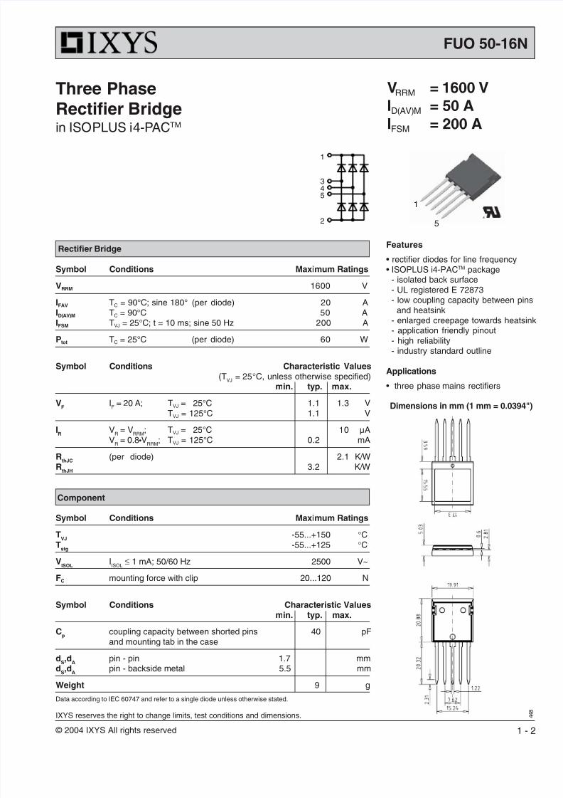
VRRM = 1600 V
ID(AV)M = 50 A
IFSM = 200 A
Three PhaseRectifier Bridgein ISOPLUS i4-PACTM
Features
rectifier diodes for line frequency• ISOPLUS i4-PACTM package
- isolated back surface- UL registered E 72873- low coupling capacity between pins
and heatsink- enlarged creepage towards heatsink- application friendly pinout- high reliability- industry standard outline
Applications
• three phase mains rectifiers
Data according to IEC 60747 and refer to a single diode unless otherwise stated.
Component
Symbol Conditions Maximum Ratings
TVJ
-55...+150 °CT
stg-55...+125 °C
VISOL IISOL ≤ 1 mA; 50/60 Hz 2500 V~
FC mounting force with clip 20...120 N
Symbol Conditions Characteristic Valuesmin. typ. max.
Cp
coupling capacity between shorted pins 40 pFand mounting tab in the case
dS,d
Apin - pin 1.7 mm
dS,d
Apin - backside metal 5.5 mm
Weight 9 g
1
345
2
1
5
Dimensions in mm (1 mm = 0.0394")
Rectifier Bridge
Symbol Conditions Maximum Ratings
VRRM 1600 V
IFAV TC = 90°C; sine 180° (per diode) 20 AID(AV)M TC = 90°C 50 AIFSM TVJ = 25°C; t = 10 ms; sine 50 Hz 200 A
Ptot TC = 25°C (per diode) 60 W
Symbol Conditions Characteristic Values(T
VJ= 25°C, unless otherwise specified)
min. typ. max.
VF
IF
= 20 A; TVJ = 25°C 1.1 1.3 VTVJ = 125°C 1.1 V
IR
VR
= VRRM
; TVJ = 25°C 10 µAV
R= 0.8•V
RRM; TVJ = 125°C 0.2 mA
RthJC
(per diode) 2.1 K/WR
thJH3.2 K/W
8/7/2019 FUO 50-16N
http://slidepdf.com/reader/full/fuo-50-16n 2/2
© 2004 IXYS All rights reserved 2 - 2
448
FUO 50-16N
IXYS reserves the right to change limits, test conditions and dimensions.
0 30 60 90 120 150
0.0 0.5 1.0 1.5 2.00
10
20
30
40
50
60
VF
A
IF
V
TVJ
=125°C
Ptot
Id(AV)M
ATA
0 10 20 30 400
20
40
60
80
100
120
140
160
180
0.001 0.01 0.1 1 100.0
0.5
1.0
1.5
2.0
2.5
ts
K/W
ZthJC
W
°C 0 40 80 120 1600
10
20
30
40
50
60
TH
Id(AV)M
A
°C
t
IFSM
0.001 0.01 0.1 10
50
100
150
200
250
300
350
TVJ
= 25°C
TVJ = 125°C
f = 50 Hz
VR = 0.8VRRM
A
s
I2t
A2s
mst
1 10100
1000VR = 0 V
TVJ
= 45°C
TVJ
= 125°C
RthHA
[K/W]
0.2
0.5
1
1.5
2
3
5
TVJ
= 25°C
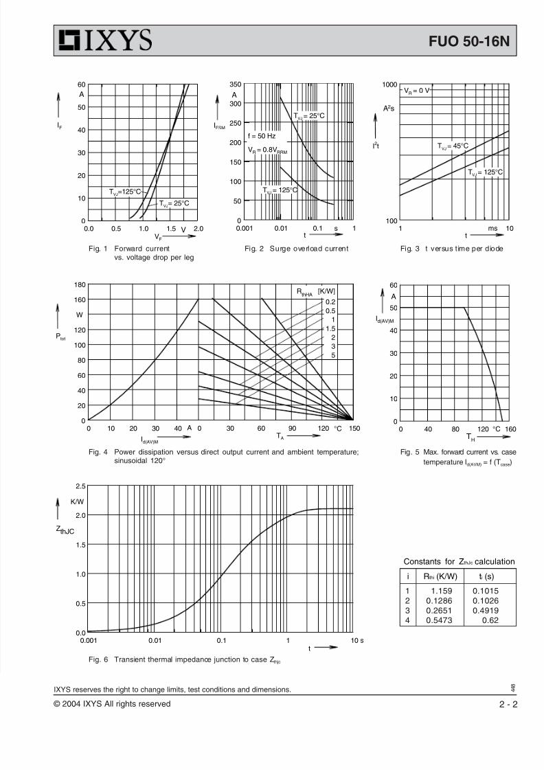
Fig. 1 Forward currentvs. voltage drop per leg
Fig. 2 Surge overload current Fig. 3 t versus time per diode
Fig. 4 Power dissipation versus direct output current and ambient temperature;sinusoidal 120°
Fig. 5 Max. forward current vs. case
temperature Id(AVM) = f (Tcase)
Fig. 6 Transient thermal impedance junction to case Zthjc
Constants for ZthJc calculation
i Rthi (K/W) ti (s)
1 1.159 0.10152 0.1286 0.10263 0.2651 0.49194 0.5473 0.62