Embed Size (px)
Citation preview

G0 PC Installation andBeam Studies
June & July 2006
Stephanie BaileyRiad Suleiman

Pockels Cell InstallationJune 20-21, 2006
• What did we accomplish?– Characterized Intensity Asymmetry (IA) Cell:
λ/4, 16°• Measured dependence of intensity asymmetry on
voltage : -23.59 ppm/V
– Aligned Pockels Cell (PC)• Degree of linear polarization = 0.45%• Degree of circular polarization = 99.9%• Minimized x and y position differences.

Pockels Cell Installation June 20-21, 2006
Steering (LP OUT)
IHWP IN IHWP OUT Goal
Δx 0.075 ± 0.017 µm
0.012 ± 0.011 µm
< 0.1 µm
Δy -0.26 ± 0.008 µm
0.20 ± 0.008 µm
< 0.1 µm
Δcharge 54.83 ± 5.37 ppm
-30.79 ± 5.52 ppm
Birefringence (LP IN)
IHWP IN IHWP OUT Goal
Δx -5.82 ± 0.012 µm
1.94 ± 0.012 µm
< 6 µm
Δy 1.43 ± 0.009 µm
-0.56 ± 0.008 µm
< 6 µm
Δcharge 701.8 ± 89.2 ppm
-3425 ± 88.8 ppm
Electrical Pickup
Δx -0.01255 ± 0.007813 µm
Δy 0.001276 ± 0.005298 µm
Δcharge 0.355 ± 3.648 ppm
Injector Happex
Δx < 0.3 µm
Δy < 0.3 µm
Δcharge
w/ photocathode3X larger ininjector
w/ photocathode20X smaller ininjector

Electron Beam StudiesJuly 9, 2006
Electrical Pickup
(PC OFF)
IHWP IN IHWP OUT
Δx -0.071 ± 0.043 µm 0.067 ± 0.038 µm
Δy 0.58 ± 0.038 µm 0.65 ± 0.037 µm
Δcharge -9.84 ± 3.34 ppm -4.02 ± 2.97 ppm
Big y position differencesnot consistent with zero!

Electron Beam StudiesJuly 10, 2006
• To diagnose the electronic noise pick-up:– Disconnected 4 cables going to QPD and put
them into an insulated sleeve– Turned off spiricon CCD, spiricon monitor,
local CCD monitor, and small scope– Unplugged PC fiber– Unplugged helicity-magnet fiber– Unplugged 4 QPD signals

Electron Beam StudiesJuly 10, 2006
PC fiber unplugged PC fiber plugged
Conclusion: The electrical noise pickup is coming from the in-time helicity fiber that travels from the helicity board to the IA and PC high voltages supplies.

Electron Beam StudiesJuly 12, 2006
• John Hansknecht found that a grounded BNC shell from a bundled cable was touching an IA BNC shell that is supposed to remain floating.
• This grounding point would indeed place real-time helicity information on to the cable that returns to the upstairs racks.
• The offending cable was relocated and the IA system was tested for proper functionality.

Electron Beam StudiesJuly 12, 2006
Electrical Pickup
(PC OFF)
IHWP IN
Δx -0.0053 ± 0.018 µm
Δy -0.0077 ± 0.016 µm
Δcharge 0.053 ± 1.99 ppm
• The position differences and charge asymmetry are consistent with zero.
• Therefore, we conclude that the cable was the source of the problem.
So we are good to go, right? No.

Electron Beam StudiesJuly 12, 2006
There is a 0.5 um position difference offset in x. Thus, we could not minimize the position differences using the RHWP and PITA.

Back Into the InjectorJuly 17, 2006
• The launch into the frequncy doubler changed since we last aligned the cell.
• This introduced satellite spots which accounted for the large position differences.
• After Matt and John realigned the doubler setup, the satellite spot went away.
Face of Pockels cell
Laser beam going throughthe PC is not point-like.

Pockels Cell InstallationJuly 17, 2006
Steering (LP OUT)
IHWP IN IHWP OUT Goal
Δx -0.10 ± 0.010 µm
0.096 ± 0.011 µm
< 0.1 µm
Δy 0.19 ± 0.0074 µm
-0.16 ± 0.007 µm
< 0.1 µm
Δcharge 30.15 ± 1.70 ppm
-43.94 ± 1.82 ppm
Birefringence (LP IN)
IHWP IN IHWP OUT Goal
Δx -7.82 ± 0.010 µm
5.90 ± 0.012 µm
< 6 µm
Δy -10.05 ± 0.0075 µm
12.48 ±0.008 µm
< 6 µm
Δcharge -3296 ± 58.12 ppm
2554 ± 70.4 ppm
Electrical Pickup
PC OFF
Δx -0.0007555 ± 0.00509 µm
Δy -0.001146 ± 0.00365 µm
Δcharge -5.405 ± 0.8676 ppm
Injector Happex
Δx < 0.3 µm
Δy < 0.3 µm
Δcharge
w/ photocathode3X larger ininjector
w/ photocathode20X smaller ininjector

Electron Beam StudiesJuly 18, 2006
PITA=0 PITA=-180

Electron Beam StudiesJuly 18, 2006
RHWP=0° RHWP=0°
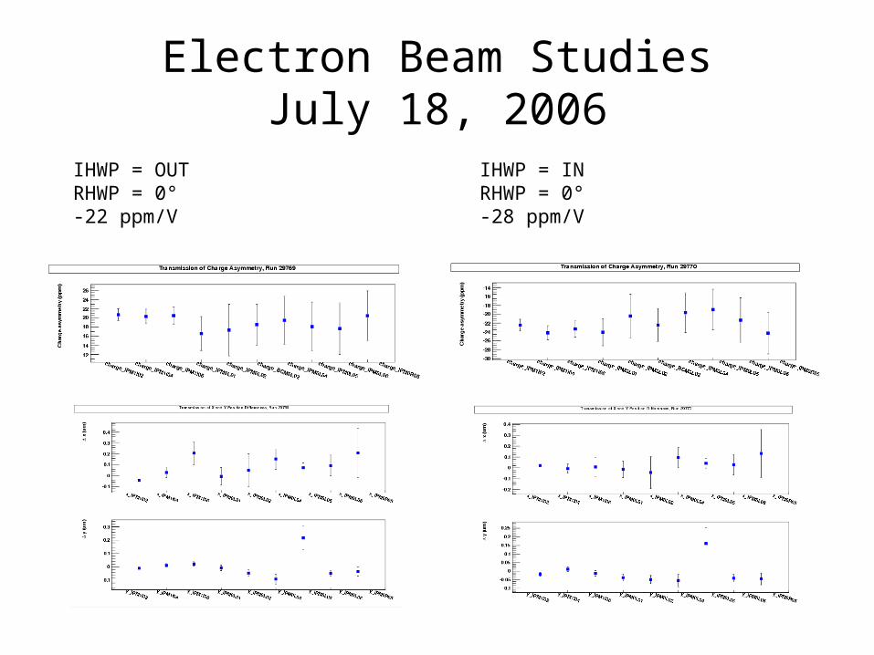
Electron Beam StudiesJuly 18, 2006
IHWP = OUTRHWP = 0°-22 ppm/V
IHWP = INRHWP = 0°-28 ppm/V

THE END