Embed Size (px)
DESCRIPTION
gambit tutorial vertex shadingtutorialhow to work with
Citation preview
© Fluent Inc. 04/17/236-1
Introductory GAMBIT Notes GAMBIT v2.0 Jan 2002
Fluent User Services Center
www.fluentusers.com
Mesh Control throughBoundary Layers
and Face Vertex Types
© Fluent Inc. 04/17/236-2
Introductory GAMBIT Notes GAMBIT v2.0 Jan 2002
Fluent User Services Center
www.fluentusers.com
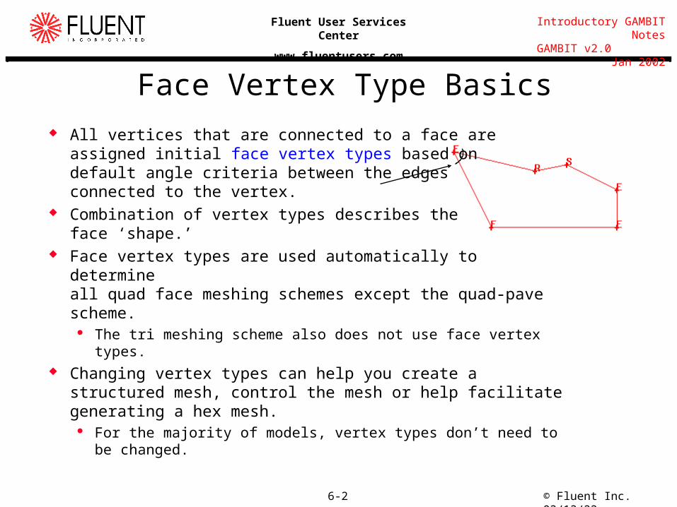
Face Vertex Type Basics
All vertices that are connected to a face are assigned initial face vertex types based on default angle criteria between the edges connected to the vertex.
Combination of vertex types describes the face ‘shape.’
Face vertex types are used automatically to determine all quad face meshing schemes except the quad-pave scheme.
The tri meshing scheme also does not use face vertex types. Changing vertex types can help you create a structured mesh,
control the mesh or help facilitate generating a hex mesh. For the majority of models, vertex types don’t need to be changed.
© Fluent Inc. 04/17/236-3
Introductory GAMBIT Notes GAMBIT v2.0 Jan 2002
Fluent User Services Center
www.fluentusers.com
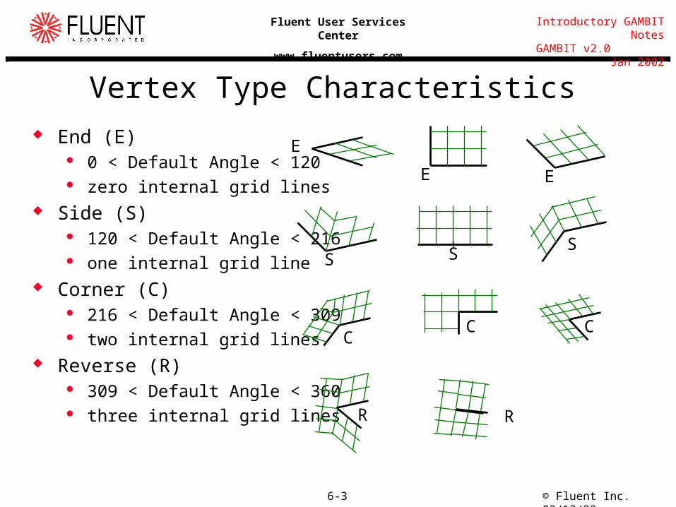
Vertex Type Characteristics End (E)
0 < Default Angle < 120 zero internal grid lines
Side (S) 120 < Default Angle < 216 one internal grid line
Corner (C) 216 < Default Angle < 309 two internal grid lines
Reverse (R) 309 < Default Angle < 360 three internal grid lines
E
E E
S SS
CC C
R R
© Fluent Inc. 04/17/236-4
Introductory GAMBIT Notes GAMBIT v2.0 Jan 2002
Fluent User Services Center
www.fluentusers.com
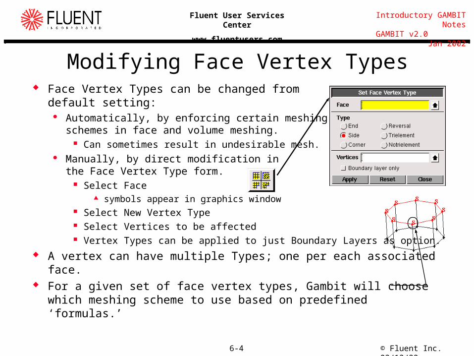
Modifying Face Vertex Types Face Vertex Types can be changed from
default setting: Automatically, by enforcing certain meshing
schemes in face and volume meshing. Can sometimes result in undesirable mesh.
Manually, by direct modification in the Face Vertex Type form.
Select Face symbols appear in graphics window
Select New Vertex Type Select Vertices to be affected Vertex Types can be applied to just Boundary Layers as option.
A vertex can have multiple Types; one per each associated face. For a given set of face vertex types, Gambit will choose which meshing
scheme to use based on predefined ‘formulas.’
© Fluent Inc. 04/17/236-5
Introductory GAMBIT Notes GAMBIT v2.0 Jan 2002
Fluent User Services Center
www.fluentusers.com
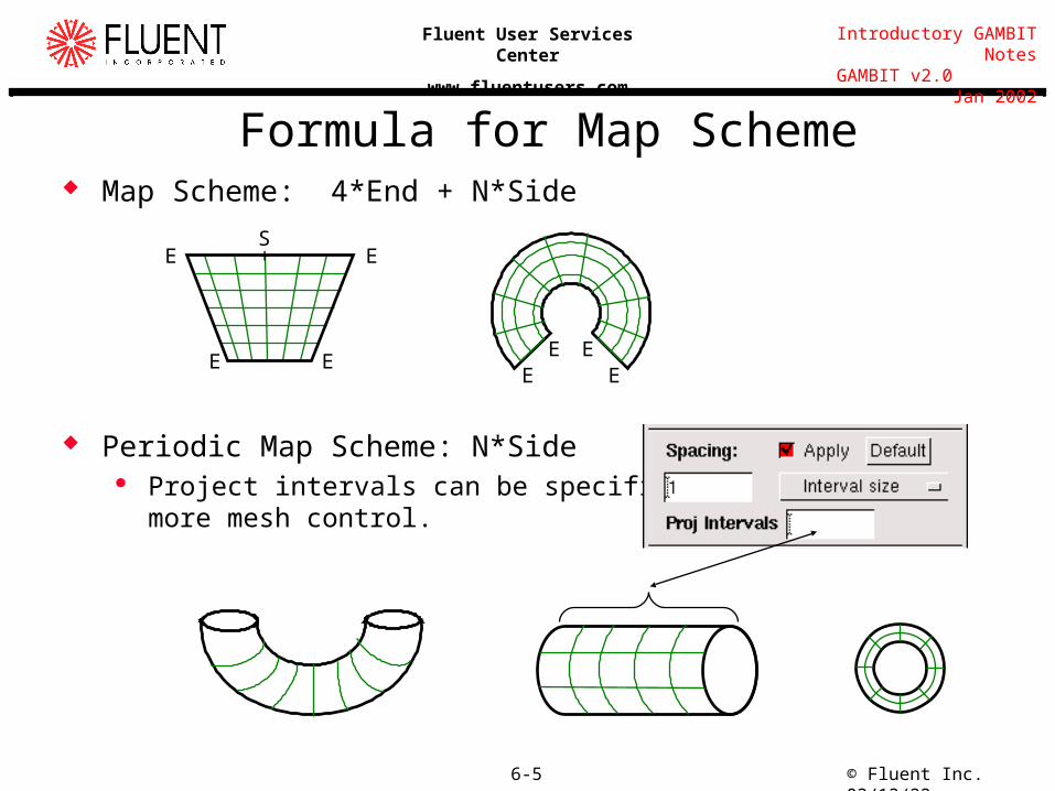
Formula for Map Scheme Map Scheme: 4*End + N*Side
Periodic Map Scheme: N*Side Project intervals can be specified for
more mesh control.
E
E
E
ES+
E EEE
© Fluent Inc. 04/17/236-6
Introductory GAMBIT Notes GAMBIT v2.0 Jan 2002
Fluent User Services Center
www.fluentusers.com
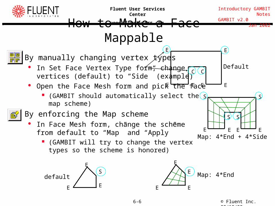
By manually changing vertex types In Set Face Vertex Type form, change
vertices (default) to “Side” (example) Open the Face Mesh form and pick the face
(GAMBIT should automatically select the map scheme)
By enforcing the Map scheme In Face Mesh form, change the scheme
from default to “Map” and “Apply” (GAMBIT will try to change the vertex
types so the scheme is honored)
How to Make a Face Mappable
E
SS
E
S
EE
S
Map: 4*End + 4*Side
E
EE
E
C
EE
CDefault
E
E
E
Sdefault Map: 4*End
E
E E
E
© Fluent Inc. 04/17/236-7
Introductory GAMBIT Notes GAMBIT v2.0 Jan 2002
Fluent User Services Center
www.fluentusers.com
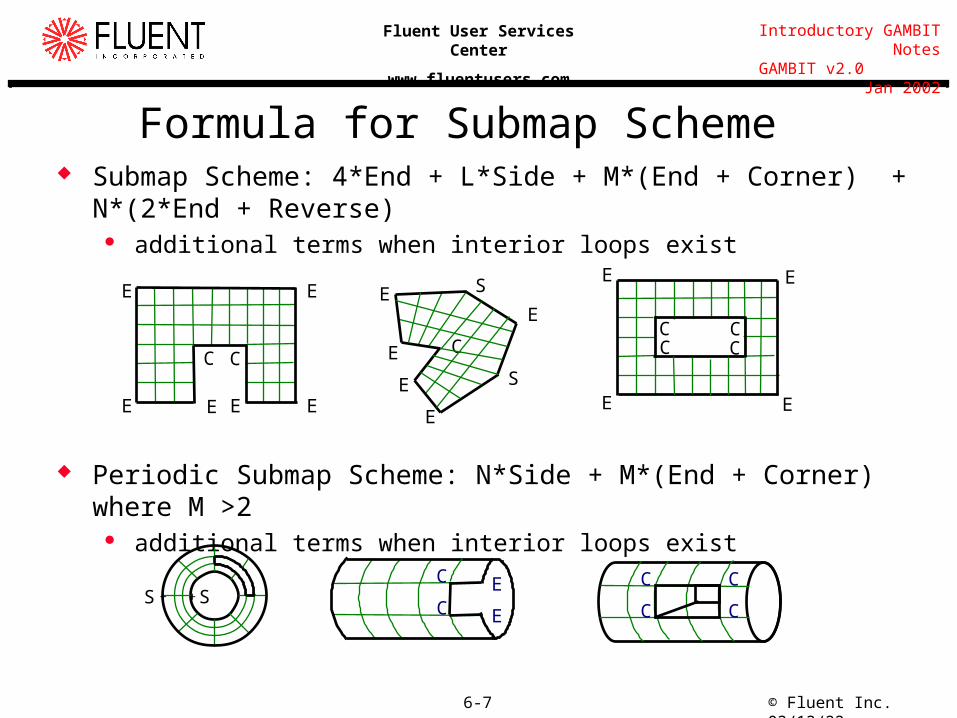
Formula for Submap Scheme Submap Scheme: 4*End + L*Side + M*(End + Corner) + N*(2*End +
Reverse) additional terms when interior loops exist
Periodic Submap Scheme: N*Side + M*(End + Corner) where M >2 additional terms when interior loops exist
E
EE
E
C
EE
CS
C
S
E
EE
E
E
C
C
C
CC
C E
E
E
C
E
E
CC
E
C
S S+ +
© Fluent Inc. 04/17/236-8
Introductory GAMBIT Notes GAMBIT v2.0 Jan 2002
Fluent User Services Center
www.fluentusers.com
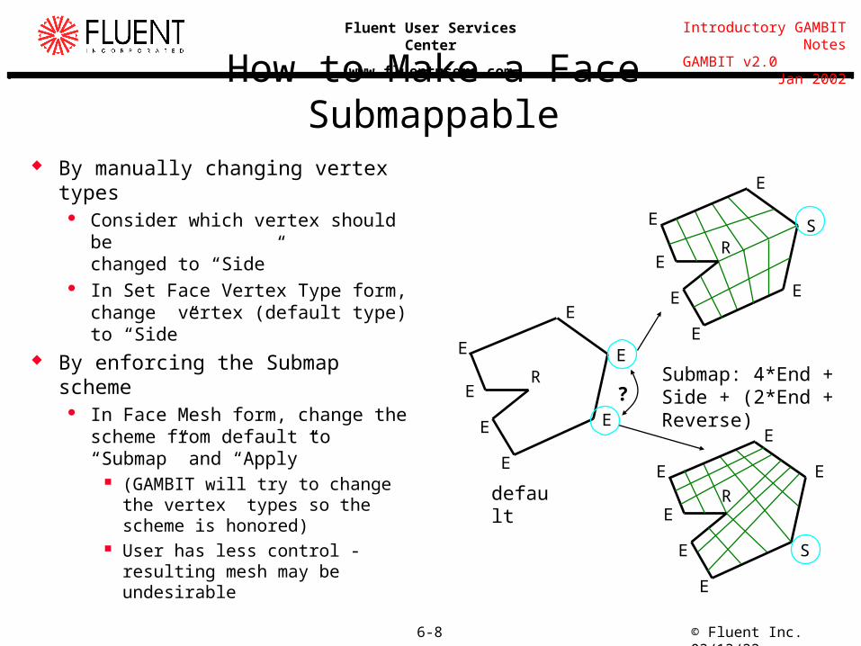
How to Make a Face Submappable By manually changing vertex types
Consider which vertex should be changed to “Side”
In Set Face Vertex Type form, change vertex (default type) to “Side”
By enforcing the Submap scheme In Face Mesh form, change the
scheme from default to “Submap” and “Apply”
(GAMBIT will try to change the vertex types so the scheme is honored)
User has less control - resulting mesh may be undesirable
R
E
E
EE
E
E
E
default
Submap: 4*End + Side + (2*End + Reverse)
R
E
E
SE
E
E
E
R
E
E S
E
E
E
E
?
© Fluent Inc. 04/17/236-9
Introductory GAMBIT Notes GAMBIT v2.0 Jan 2002
Fluent User Services Center
www.fluentusers.com
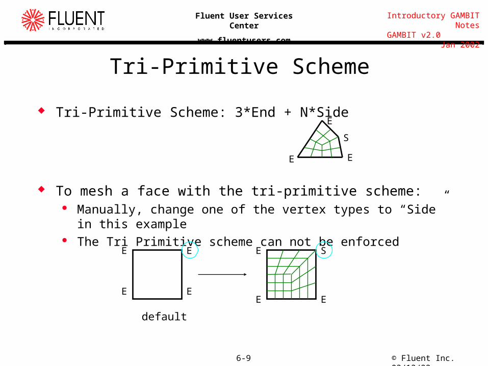
Tri-Primitive Scheme
Tri-Primitive Scheme: 3*End + N*Side
To mesh a face with the tri-primitive scheme: Manually, change one of the vertex types to “Side” in this example The Tri Primitive scheme can not be enforced
E
S
E
E
E
E
E
E
E
E
E
S
default
© Fluent Inc. 04/17/236-10
Introductory GAMBIT Notes GAMBIT v2.0 Jan 2002
Fluent User Services Center
www.fluentusers.com
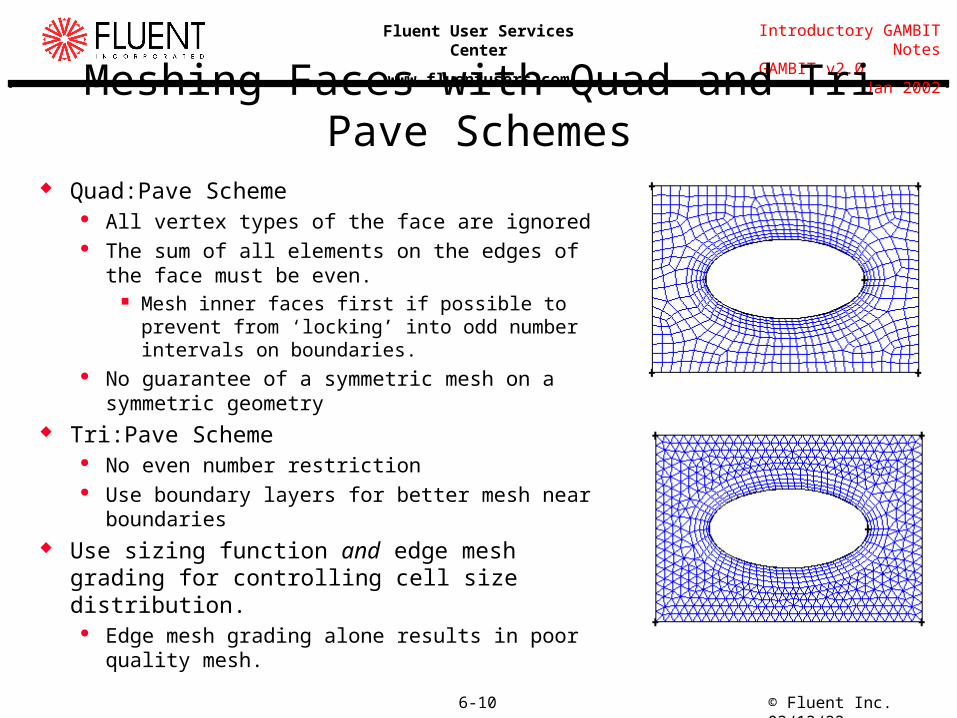
Meshing Faces with Quad and Tri Pave Schemes Quad:Pave Scheme
All vertex types of the face are ignored The sum of all elements on the edges of the face must
be even. Mesh inner faces first if possible to prevent from
‘locking’ into odd number intervals on boundaries. No guarantee of a symmetric mesh on a symmetric
geometry Tri:Pave Scheme
No even number restriction Use boundary layers for better mesh near boundaries
Use sizing function and edge mesh grading for controlling cell size distribution.
Edge mesh grading alone results in poor quality mesh.
© Fluent Inc. 04/17/236-11
Introductory GAMBIT Notes GAMBIT v2.0 Jan 2002
Fluent User Services Center
www.fluentusers.com
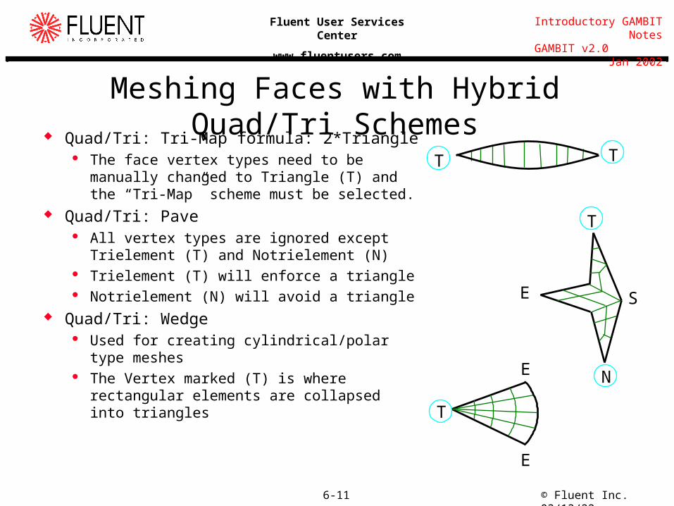
Meshing Faces with Hybrid Quad/Tri Schemes
Quad/Tri: Tri-Map formula: 2*Triangle The face vertex types need to be manually
changed to Triangle (T) and the “Tri-Map” scheme must be selected.
Quad/Tri: Pave All vertex types are ignored except Trielement
(T) and Notrielement (N) Trielement (T) will enforce a triangle Notrielement (N) will avoid a triangle
Quad/Tri: Wedge Used for creating cylindrical/polar type meshes The Vertex marked (T) is where rectangular
elements are collapsed into triangles
T T
E
N
T
S
T
E
E
© Fluent Inc. 04/17/236-12
Introductory GAMBIT Notes GAMBIT v2.0 Jan 2002
Fluent User Services Center
www.fluentusers.com
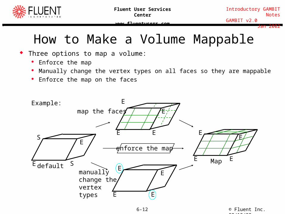
How to Make a Volume Mappable Three options to map a volume:
Enforce the map Manually change the vertex types on all faces so they are mappable Enforce the map on the faces
E
E
E
EE
E
S
manually change the vertex types
S Mapdefault
E
EE
E
E
E
E
E
map the faces
enforce the map
Example:
© Fluent Inc. 04/17/236-13
Introductory GAMBIT Notes GAMBIT v2.0 Jan 2002
Fluent User Services Center
www.fluentusers.com
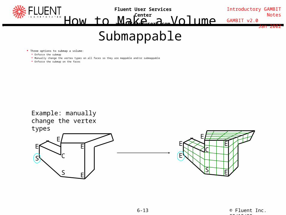
How to Make a Volume Submappable Three options to submap a volume:
Enforce the submap Manually change the vertex types on all faces so they are mappable and/or submappable Enforce the submap on the faces
EE
C
E
ES
S
EE
CE
ES
E
Example: manually change the vertex types
© Fluent Inc. 04/17/236-14
Introductory GAMBIT Notes GAMBIT v2.0 Jan 2002
Fluent User Services Center
www.fluentusers.com
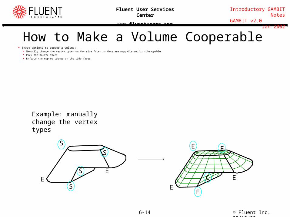
How to Make a Volume Cooperable Three options to cooper a volume:
Manually change the vertex types on the side faces so they are mappable and/or submappable Pick the source faces Enforce the map or submap on the side faces
EE
S
S
S
S
E
E
E
E E
C
Example: manually change the vertex types
© Fluent Inc. 04/17/236-15
Introductory GAMBIT Notes GAMBIT v2.0 Jan 2002
Fluent User Services Center
www.fluentusers.com
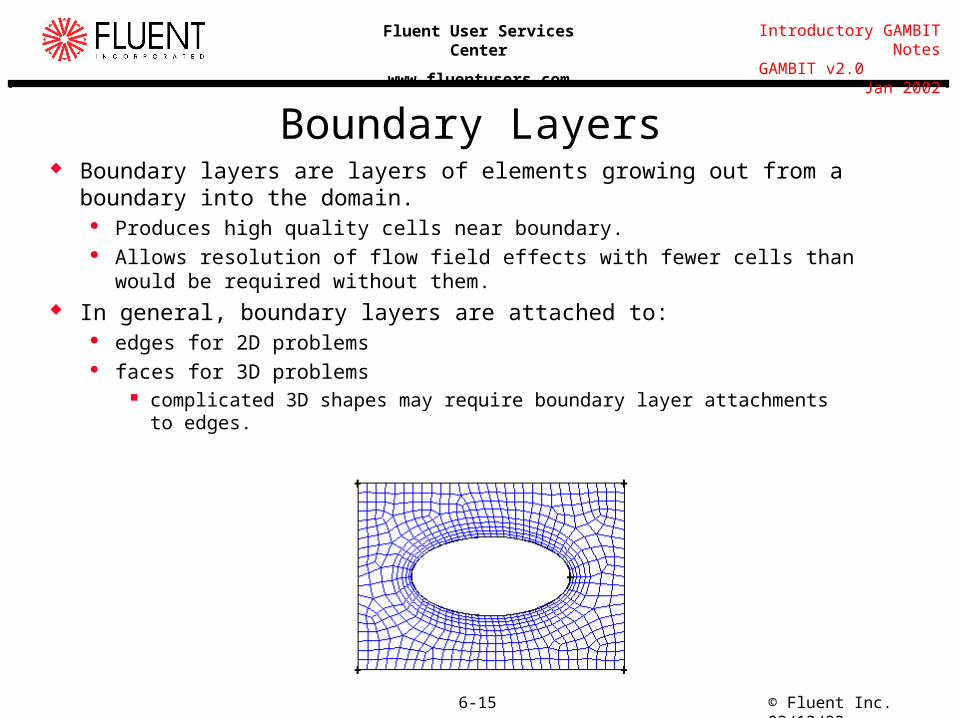
Boundary Layers Boundary layers are layers of elements growing out from a boundary into the
domain. Produces high quality cells near boundary. Allows resolution of flow field effects with fewer cells than would be required
without them. In general, boundary layers are attached to:
edges for 2D problems faces for 3D problems
complicated 3D shapes may require boundary layer attachments to edges.
© Fluent Inc. 04/17/236-16
Introductory GAMBIT Notes GAMBIT v2.0 Jan 2002
Fluent User Services Center
www.fluentusers.com
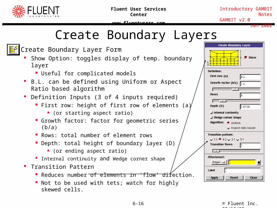
Create Boundary Layers Create Boundary Layer Form
Show Option: toggles display of temp. boundary layer Useful for complicated models
B.L. can be defined using Uniform or Aspect Ratio based algorithm
Definition Inputs (3 of 4 inputs required) First row: height of first row of elements (a)
(or starting aspect ratio) Growth factor: factor for geometric series (b/a) Rows: total number of element rows Depth: total height of boundary layer (D)
(or ending aspect ratio) Internal continuity and Wedge corner shape
Transition Pattern Reduces number of elements in ‘flow’ direction. Not to be used with tets; watch for highly skewed cells.
© Fluent Inc. 04/17/236-17
Introductory GAMBIT Notes GAMBIT v2.0 Jan 2002
Fluent User Services Center
www.fluentusers.com
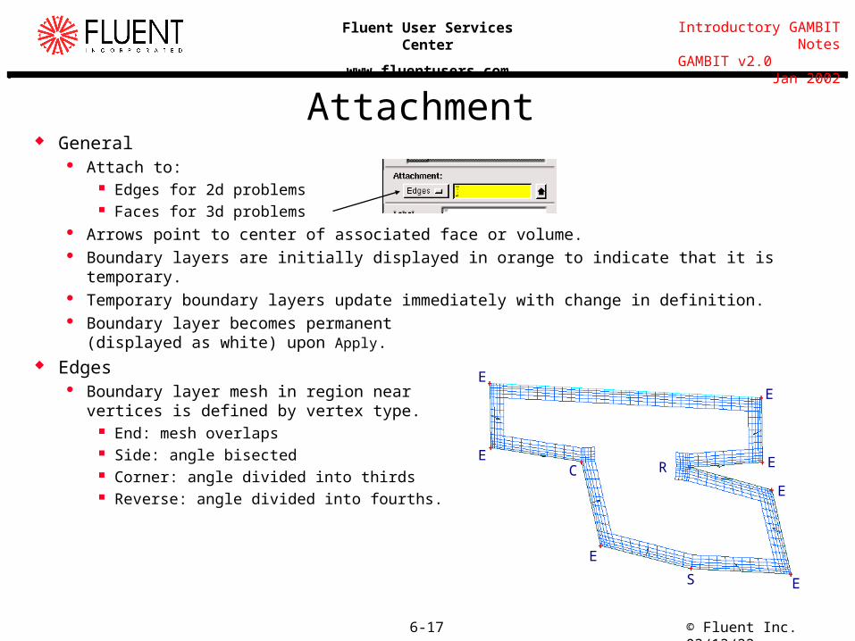
Attachment General
Attach to: Edges for 2d problems Faces for 3d problems
Arrows point to center of associated face or volume. Boundary layers are initially displayed in orange to indicate that it is temporary. Temporary boundary layers update immediately with change in definition. Boundary layer becomes permanent
(displayed as white) upon Apply. Edges
Boundary layer mesh in region near vertices is defined by vertex type.
End: mesh overlaps Side: angle bisected Corner: angle divided into thirds Reverse: angle divided into fourths.
E
E
ES
CE
E
E
R
E
© Fluent Inc. 04/17/236-18
Introductory GAMBIT Notes GAMBIT v2.0 Jan 2002
Fluent User Services Center
www.fluentusers.com
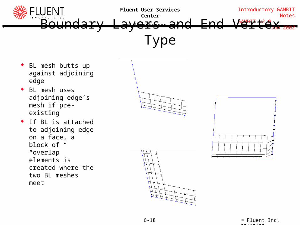
Boundary Layers and End Vertex Type
BL mesh butts up against adjoining edge
BL mesh uses adjoining edge’s mesh if pre-existing
If BL is attached to adjoining edge on a face, a block of “overlap” elements is created where the two BL meshes meet
© Fluent Inc. 04/17/236-19
Introductory GAMBIT Notes GAMBIT v2.0 Jan 2002
Fluent User Services Center
www.fluentusers.com
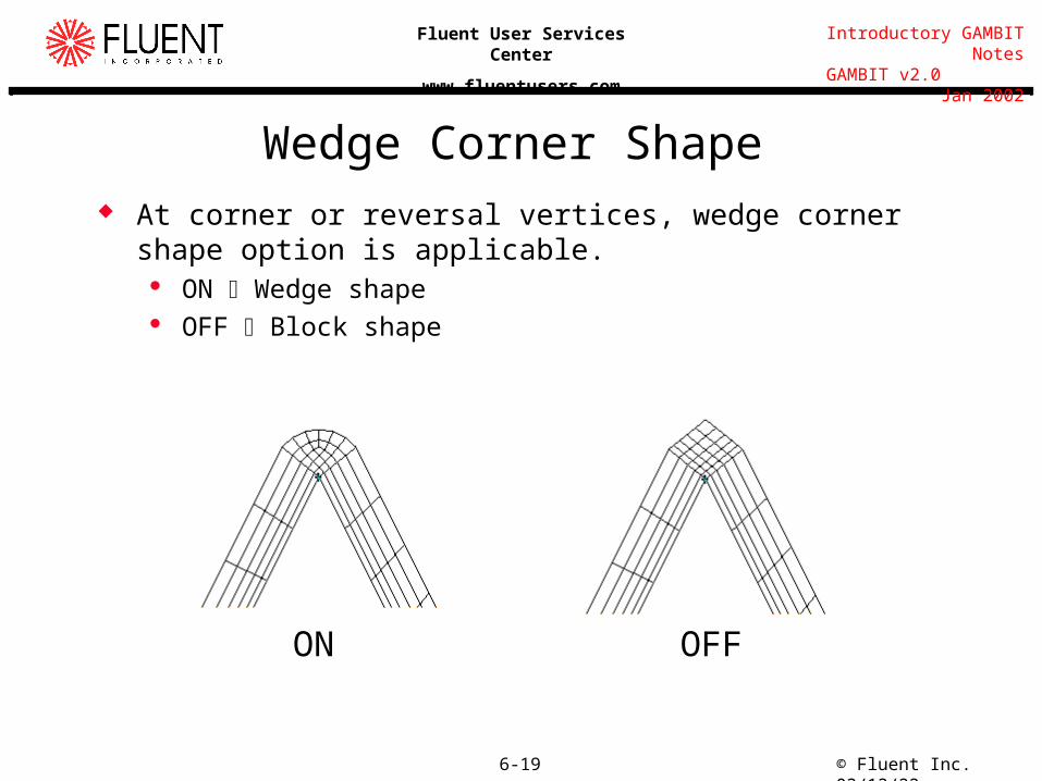
Wedge Corner Shape At corner or reversal vertices, wedge corner shape option is
applicable. ON Wedge shape OFF Block shape
ON OFF
© Fluent Inc. 04/17/236-20
Introductory GAMBIT Notes GAMBIT v2.0 Jan 2002
Fluent User Services Center
www.fluentusers.com
Attachment to Faces A boundary layer attached to a face may ‘imprint’ the adjoining faces.
The imprint is displayed graphically on adjoining faces. Imprinting will depend upon b.l. attachments of adjoining faces and state of
internal continuity. If adjoining faces do not have b.l. attachments-
Attaching boundary layer to face: Gambit checks angle bounded by attachment and adjoining faces. Will imprint (become visible) the adjoining faces if angle is less than default
angle (135o). Will not imprint adjoining faces if angle is larger than default.
b.l. is still created but may not impact mesh.
If adjoining faces have b.l. attachments- Imprinting and overlap region depends upon state of internal continuity.
© Fluent Inc. 04/17/236-21
Introductory GAMBIT Notes GAMBIT v2.0 Jan 2002
Fluent User Services Center
www.fluentusers.com
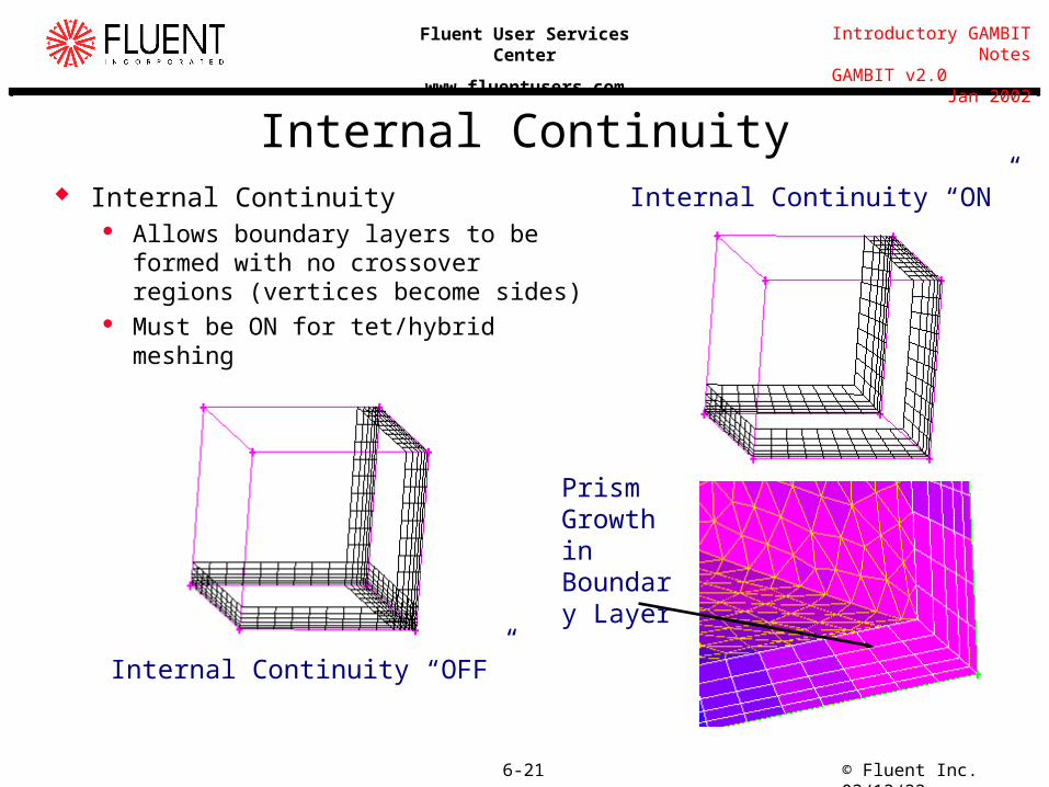
Internal Continuity Internal Continuity
Allows boundary layers to be formed with no crossover regions (vertices become sides)
Must be ON for tet/hybrid meshing
Internal Continuity “ON”
Internal Continuity “OFF”
Prism Growth in Boundary Layer


![Gambit [M.M.udovich, 1980 - Russian]](https://img.pdfslide.tips/doc/110x75/55cf97c8550346d0339399da/gambit-mmudovich-1980-russian.jpg)