Embed Size (px)
Citation preview

هيئة التقييس لدول مجلس التعاون لدول الخليج العربيةGCC STANDARDIZATION ORGANIZATION (GSO)
نهائي: مشروع
GSO 2/1 /FDS/ 15622 : 2012
ISO 15622:2010
االختبارإجراءات وألداءمتطلبات ا – )تثبيت السرعة(السرعة في مهيئات التحكم نظم --نظم النقل الذآية Intelligent transport systems -- Adaptive Cruise Control systems --
Performance requirements and test procedures
إعداد
الفرعية لقطاع مواصفات المركبات واإلطاراتاللجنة الفنية الخليجية
ظات بشأنها، لذلك فإنها هـذه الوثـيقة مـشروع لمواصفة قياسية خليجية تم توزيعها إلبداء الرأي والملحو
عرضـة للتغييـر والتبديل، وال يجوز الرجوع إليها كمواصفة قياسية خليجية إال بعد اعتمادها من مجلس
.إدارة الهيئة
تقديمهيـئة التقييس لدول مجلس التعاون لدول الخليج العربية هيئة إقليمية تضم في عضويتها األجهزة الوطنية
ل الخليج العربية ، ومن مهام الهيئة إعداد المواصفات القياسية الخليجية للمواصـفات والمقايـيس فـي دو
.بواسطة لجان فنية متخصصة
– ٢وقد قامت هيئة التقييس لدول مجلس التعاون لدول الخليج العربية ضمن برنامج عمل اللجنة الفنية رقم
بتبني المواصفة القياسية " اتالخليجـية الفرعية لقطاع مواصفات المركبات واإلطار اللجـنة الفنـية " ١
تثبيت (السرعة في مهيئات التحكم نظم --نظم النقل الذكية " )٢٠١٠ :١٥٦٢٢آيزو ( رقـم الدولـية
وقامت . للتقييس لدوليةاللجنة ا "درتها والتي أص – "االختبار إجـراءات و ألداءمتطلـبات ا – )الـسرعة
كمواصفة قياسية وقد اعتمدت هذه المواصفة . بإعداد مشروع هذه المواصفة ) يةالمملكـة العربية السعود (
( وذلك في اجتماع مجلس إدارة الهيئة رقم دون إدخال أية تعديالت فنية عليها خليجـية بلغـتها األصلية
.م/ / هـ ، الموافق / / ، الذي عقد بتاريخ )
Foreword
GCC Standardization Organization (GSO) is a regional Organization which consists of the National Standards Bodies of GCC member States. One of GSO main functions is to issue Gulf Standards through specialized technical committees (TCs).
GSO through the technical program of committee TC No.2-1: "The Gulf technical Subcommittee for vehicles and tyres standards” has adopted the European Standard No. : (ISO 15622: 2010) “Intelligent transport systems -- Adaptive Cruise Control systems -- Performance requirements and test procedures " issued by (International Committee for Standardization) in its original language. The Draft Standard has been prepared by (Kingdom of Saudia Arabia).This standard has been approved as Gulf Standard without any technical modifications by GSO Board of Directors in its meeting No..../.... …….held on / / / H , / / G

Reference numberISO 15622:2010(E)
© ISO 2010
INTERNATIONAL STANDARD
ISO15622
Second edition2010-04-15
Intelligent transport systems — Adaptive Cruise Control systems — Performance requirements and test procedures
Systèmes intelligents de transports — Systèmes stabilisateurs de vitesse adaptés — Exigences de performance et modes opératoires
ISO 15622:2010(E)
PDF disclaimer This PDF file may contain embedded typefaces. In accordance with Adobe's licensing policy, this file may be printed or viewed but shall not be edited unless the typefaces which are embedded are licensed to and installed on the computer performing the editing. In downloading this file, parties accept therein the responsibility of not infringing Adobe's licensing policy. The ISO Central Secretariat accepts no liability in this area.
Adobe is a trademark of Adobe Systems Incorporated.
Details of the software products used to create this PDF file can be found in the General Info relative to the file; the PDF-creation parameters were optimized for printing. Every care has been taken to ensure that the file is suitable for use by ISO member bodies. In the unlikely event that a problem relating to it is found, please inform the Central Secretariat at the address given below.
COPYRIGHT PROTECTED DOCUMENT © ISO 2010 All rights reserved. Unless otherwise specified, no part of this publication may be reproduced or utilized in any form or by any means, electronic or mechanical, including photocopying and microfilm, without permission in writing from either ISO at the address below or ISO's member body in the country of the requester.
ISO copyright office Case postale 56 • CH-1211 Geneva 20 Tel. + 41 22 749 01 11 Fax + 41 22 749 09 47 E-mail [email protected] Web www.iso.org
Published in Switzerland
ii © ISO 2010 – All rights reserved

ISO 15622:2010(E)
© ISO 2010 – All rights reserved iii
Contents Page
Foreword ............................................................................................................................................................iv Introduction.........................................................................................................................................................v 1 Scope ......................................................................................................................................................1 2 Normative references............................................................................................................................1 3 Terms and definitions ...........................................................................................................................1 4 Symbols and abbreviated terms ..........................................................................................................3 4.1 Symbols..................................................................................................................................................3 4.2 Abbreviated terms .................................................................................................................................4 5 Classification .........................................................................................................................................5 5.1 Type of ACC systems............................................................................................................................5 5.2 Classification of curve capabilities .....................................................................................................5 6 Requirements.........................................................................................................................................5 6.1 Basic control strategy...........................................................................................................................5 6.2 Functionality ..........................................................................................................................................6 6.3 Basic driver interface and intervention capabilities ..........................................................................9 6.4 Operational limits ................................................................................................................................10 6.5 Activation of brake lights (ACC type 2 only) ......................................................................................11 6.6 Failure reactions..................................................................................................................................11 7 Performance evaluation test methods ..............................................................................................12 7.1 Environmental conditions ..................................................................................................................12 7.2 Test target specification .....................................................................................................................12 7.3 Target acquisition range test (see 6.2.4.2) ........................................................................................13 7.4 Target discrimination test (see 6.2.4.3) .............................................................................................14 7.5 Curve capability test (see 6.2.4.4) ......................................................................................................16 Annex A (normative) Technical information ..................................................................................................19 Bibliography......................................................................................................................................................25
ISO 15622:2010(E)
iv © ISO 2010 – All rights reserved
Foreword
ISO (the International Organization for Standardization) is a worldwide federation of national standards bodies (ISO member bodies). The work of preparing International Standards is normally carried out through ISO technical committees. Each member body interested in a subject for which a technical committee has been established has the right to be represented on that committee. International organizations, governmental and non-governmental, in liaison with ISO, also take part in the work. ISO collaborates closely with the International Electrotechnical Commission (IEC) on all matters of electrotechnical standardization.
International Standards are drafted in accordance with the rules given in the ISO/IEC Directives, Part 2.
The main task of technical committees is to prepare International Standards. Draft International Standards adopted by the technical committees are circulated to the member bodies for voting. Publication as an International Standard requires approval by at least 75 % of the member bodies casting a vote.
Attention is drawn to the possibility that some of the elements of this document may be the subject of patent rights. ISO shall not be held responsible for identifying any or all such patent rights.
ISO 15622 was prepared by Technical Committee ISO/TC 204, Intelligent transport systems.
This second edition cancels and replaces the first edition (ISO 15622:2002) which has been technically revised.

ISO 15622:2010(E)
© ISO 2010 – All rights reserved v
Introduction
The main system function of Adaptive Cruise Control is to control vehicle speed adaptively to a forward vehicle by using information about: (1) ranging to forward vehicles, (2) the motion of the subject (ACC equipped) vehicle and (3) driver commands (see Figure 1). Based upon the information acquired, the controller (identified as “ACC control strategy” in Figure 1) sends commands to actuators for carrying out its longitudinal control strategy and it also sends status information to the driver.
ACC control strategy
Driver information
Detection and ranging of forward vehicles
Acquisi tion of driver commands
Subject vehicle motion determination
Actuators for longitudinal control
Environment Vehicle Driver
Figure 1 — Functional ACC elements
The goal of ACC is a partial automation of the longitudinal vehicle control and the reduction of the workload of the driver with the aim of supporting and relieving the driver in a convenient manner.
This International Standard can be used as a system level standard by other standards, which extend the ACC to a more detailed standard, e.g. for specific detection and ranging sensor concepts or higher level of functionality. Therefore, issues like specific requirements for the detection and ranging sensor function and performance or communication links for co-operative solutions will not be considered here.

INTERNATIONAL STANDARD ISO 15622:2010(E)
© ISO 2010 – All rights reserved 1
Intelligent transport systems — Adaptive Cruise Control systems — Performance requirements and test procedures
1 Scope
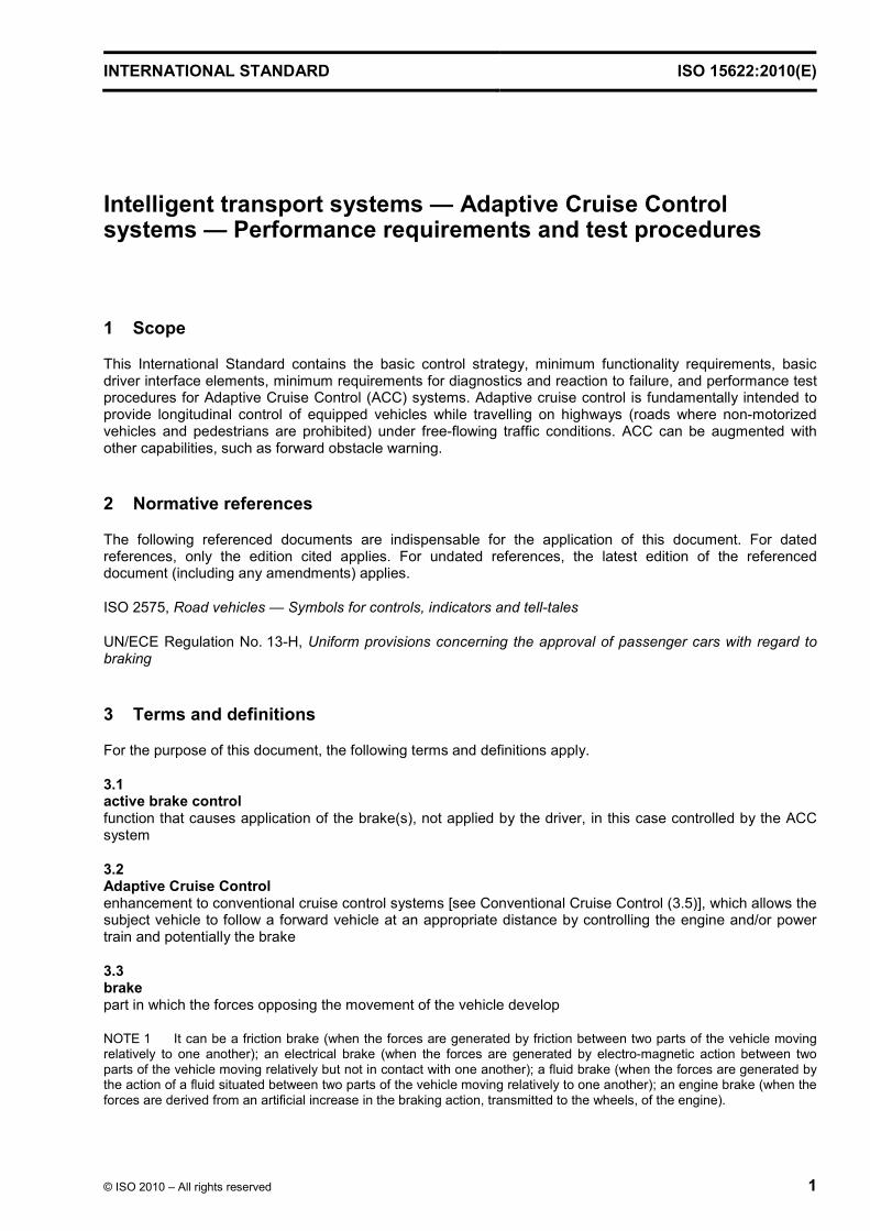
This International Standard contains the basic control strategy, minimum functionality requirements, basic driver interface elements, minimum requirements for diagnostics and reaction to failure, and performance test procedures for Adaptive Cruise Control (ACC) systems. Adaptive cruise control is fundamentally intended to provide longitudinal control of equipped vehicles while travelling on highways (roads where non-motorized vehicles and pedestrians are prohibited) under free-flowing traffic conditions. ACC can be augmented with other capabilities, such as forward obstacle warning.
2 Normative references
The following referenced documents are indispensable for the application of this document. For dated references, only the edition cited applies. For undated references, the latest edition of the referenced document (including any amendments) applies.
ISO 2575, Road vehicles — Symbols for controls, indicators and tell-tales
UN/ECE Regulation No. 13-H, Uniform provisions concerning the approval of passenger cars with regard to braking
3 Terms and definitions
For the purpose of this document, the following terms and definitions apply.
3.1 active brake control function that causes application of the brake(s), not applied by the driver, in this case controlled by the ACC system
3.2 Adaptive Cruise Control enhancement to conventional cruise control systems [see Conventional Cruise Control (3.5)], which allows the subject vehicle to follow a forward vehicle at an appropriate distance by controlling the engine and/or power train and potentially the brake
3.3 brake part in which the forces opposing the movement of the vehicle develop
NOTE 1 It can be a friction brake (when the forces are generated by friction between two parts of the vehicle moving relatively to one another); an electrical brake (when the forces are generated by electro-magnetic action between two parts of the vehicle moving relatively but not in contact with one another); a fluid brake (when the forces are generated by the action of a fluid situated between two parts of the vehicle moving relatively to one another); an engine brake (when the forces are derived from an artificial increase in the braking action, transmitted to the wheels, of the engine).

ISO 15622:2010(E)
2 © ISO 2010 – All rights reserved
NOTE 2 Adapted from UN ECE Regulation No. 13-H:1998, definition 2.6.
NOTE 3 For the purposes of this International Standard, transmission control devices are not considered as brakes.
3.4 clearance distance from the forward vehicle's trailing surface to the subject vehicle's leading surface
3.5 Conventional Cruise Control system capable of controlling the speed of a vehicle as set by the driver
3.6 forward vehicle vehicle in front of and moving in the same direction and travelling on the same roadway as the subject vehicle (3.11)
3.7 free-flowing traffic smooth-flowing and heavy traffic excluding stop and go and emergency braking situations
3.8 time gap τ value calculated from vehicle speed v and clearance c by: τ = c/v
c
v
3.9 set speed desired travel speed, set either by the driver or by some control system that is external to the ACC system
NOTE The set speed is the maximum desired speed of the vehicle while under ACC control.
3.10 steady state condition whereby the value of the described parameter does not change with respect to time, distance, etc.
3.11 subject vehicle vehicle equipped with the system in question and related to the topic of discussion
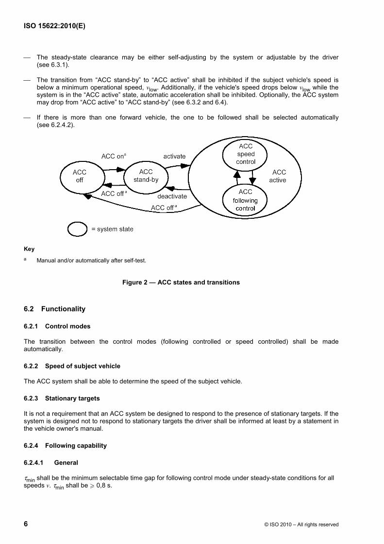
3.12 ACC system states For the purposes of this International Standard, three system states are distinguished (see Figure 2)
3.12.1 ACC off state state in which direct access for activation of “ACC active state” is disabled
3.12.2 ACC stand-by state state in which there is no longitudinal control by ACC system and the system is ready for activation by the driver
ISO 15622:2010(E)
© ISO 2010 – All rights reserved 3
3.12.3 ACC active state state in which the system controls speed and/or clearance
3.12.3.1 ACC speed control sub-state state in which the system controls the speed according to the set speed
3.12.3.2 ACC following control sub-state state in which the system controls the clearance to the target vehicle according to the selected time gap
3.13 target vehicle vehicle that the subject vehicle follows
3.14 stationary object object in front of the subject vehicle which is stationary
4 Symbols and abbreviated terms
4.1 Symbols
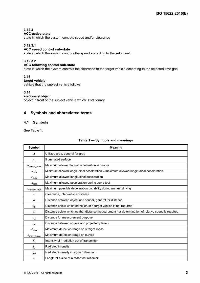
See Table 1.
Table 1 — Symbols and meanings
Symbol Meaning
A Utilized area, general for area
At Illuminated surface
alateral_max Maximum allowed lateral acceleration in curves
amin Minimum allowed longitudinal acceleration = maximum allowed longitudinal deceleration
amax Maximum allowed longitudinal acceleration
atest Maximum allowed acceleration during curve test
avehicle_max Maximum possible deceleration capability during manual driving
c Clearance, inter-vehicle distance
d Distance between object and sensor, general for distance
d0 Distance below which detection of a target vehicle is not required
d1 Distance below which neither distance measurement nor determination of relative speed is required
d2 Distance for measurement purpose
dA Distance between source and projected plane A
dmax Maximum detection range on straight roads
dmax_curve Maximum detection range on curves
Et Intensity of irradiation out of transmitter
I0 Radiated intensity
Iref Radiated intensity in a given direction
L Length of a side of a radar test reflector
ISO 15622:2010(E)
4 © ISO 2010 – All rights reserved
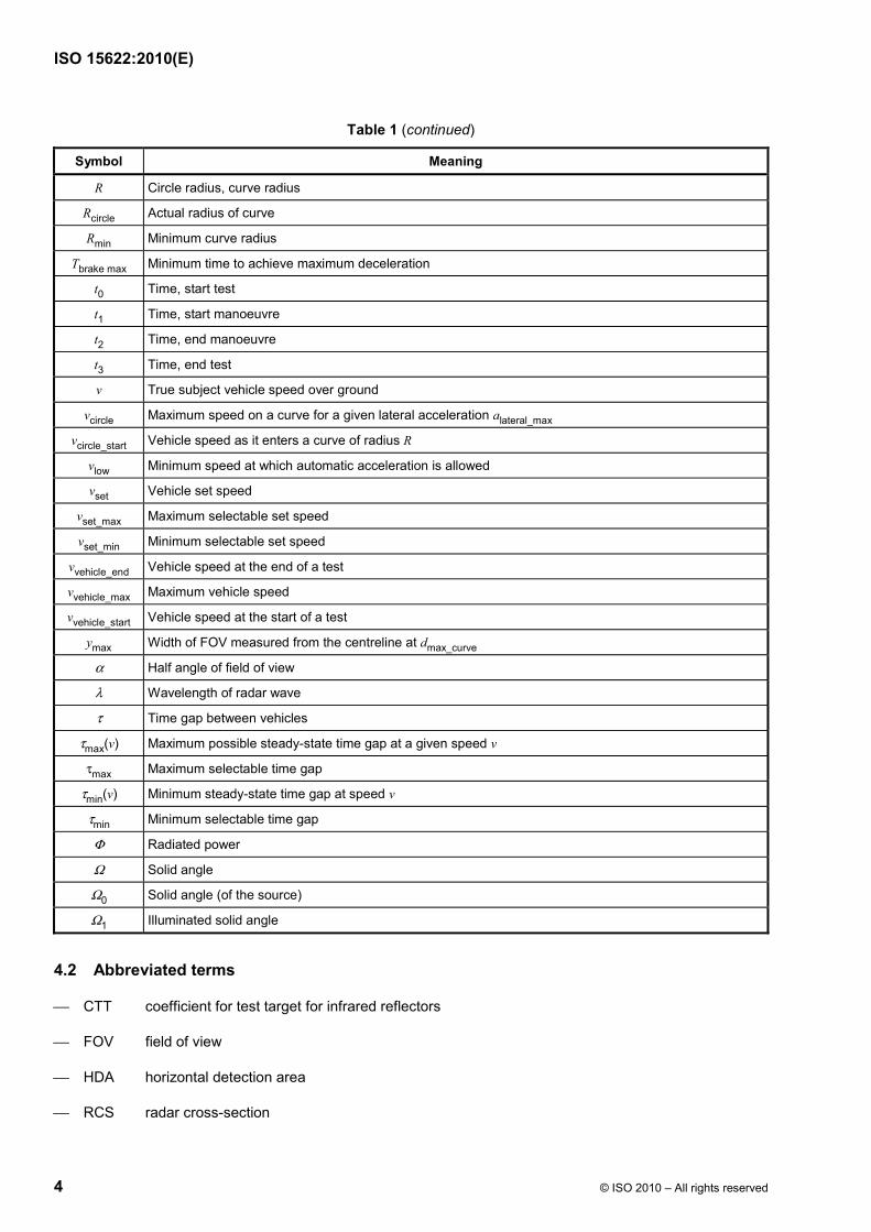
Table 1 (continued)
Symbol Meaning
R Circle radius, curve radius
Rcircle Actual radius of curve
Rmin Minimum curve radius
Tbrake max Minimum time to achieve maximum deceleration
t0 Time, start test
t1 Time, start manoeuvre
t2 Time, end manoeuvre
t3 Time, end test
v True subject vehicle speed over ground
vcircle Maximum speed on a curve for a given lateral acceleration alateral_max
vcircle_start Vehicle speed as it enters a curve of radius R
vlow Minimum speed at which automatic acceleration is allowed
vset Vehicle set speed
vset_max Maximum selectable set speed
vset_min Minimum selectable set speed
vvehicle_end Vehicle speed at the end of a test
vvehicle_max Maximum vehicle speed
vvehicle_start Vehicle speed at the start of a test
ymax Width of FOV measured from the centreline at dmax_curve
α Half angle of field of view
λ Wavelength of radar wave
τ Time gap between vehicles
τmax(v) Maximum possible steady-state time gap at a given speed v
τmax Maximum selectable time gap
τmin(v) Minimum steady-state time gap at speed v
τmin Minimum selectable time gap
Φ Radiated power
Ω Solid angle
Ω0 Solid angle (of the source)
Ω1 Illuminated solid angle
4.2 Abbreviated terms
⎯ CTT coefficient for test target for infrared reflectors
⎯ FOV field of view
⎯ HDA horizontal detection area
⎯ RCS radar cross-section

ISO 15622:2010(E)
© ISO 2010 – All rights reserved 5
5 Classification
5.1 Type of ACC systems
Different configurations of actuators for longitudinal control result in very different system behaviour. Therefore four types of ACC systems are addressed in this International Standard. See Table 2.
Table 2 — Classification of ACC system types
Type Manual clutch operation required Active brake control
1a yes no
1b no no
2a yes yes
2b no yes
The deceleration capability of the ACC system shall be clearly stated in the vehicle owner's manual. In case of active brake intervention in vehicles with a clutch pedal (type 2a) the driver shall be informed clearly and early about a potential conflict between brake and engine idle control, if the clutch cannot be disengaged automatically. A practicable and unambiguous handing-over procedure shall be provided for the driver. See 6.3.1.
5.2 Classification of curve capabilities
This International Standard is applicable to ACC systems of different curve capabilities as specified in Table 3.
Table 3 — ACC performance classifications
Dimensions in metres
Performance class Curve radius capability
I no performance capability claimed
II W 500
III W 250
IV W 125
6 Requirements
6.1 Basic control strategy
NOTE Manual transition describes a switch to enable/disable ACC function. Automatic switch-off can be forced by failure reaction.
ACC systems shall, as a minimum, provide the following control strategy and state transitions. The following constitutes the fundamental behaviour of ACC systems.
⎯ When the ACC is active, the vehicle speed shall be controlled automatically either to maintain a clearance to a forward vehicle, or to maintain the set speed, whichever speed is lower. The change between these two control modes is made automatically by the ACC system.
ISO 15622:2010(E)
6 © ISO 2010 – All rights reserved
⎯ The steady-state clearance may be either self-adjusting by the system or adjustable by the driver (see 6.3.1).
⎯ The transition from “ACC stand-by” to “ACC active” shall be inhibited if the subject vehicle's speed is below a minimum operational speed, vlow. Additionally, if the vehicle's speed drops below vlow while the system is in the “ACC active” state, automatic acceleration shall be inhibited. Optionally, the ACC system may drop from “ACC active” to “ACC stand-by” (see 6.3.2 and 6.4).
⎯ If there is more than one forward vehicle, the one to be followed shall be selected automatically (see 6.2.4.2).
Key a Manual and/or automatically after self-test.
Figure 2 — ACC states and transitions
6.2 Functionality
6.2.1 Control modes
The transition between the control modes (following controlled or speed controlled) shall be made automatically.
6.2.2 Speed of subject vehicle
The ACC system shall be able to determine the speed of the subject vehicle.
6.2.3 Stationary targets
It is not a requirement that an ACC system be designed to respond to the presence of stationary targets. If the system is designed not to respond to stationary targets the driver shall be informed at least by a statement in the vehicle owner's manual.
6.2.4 Following capability
6.2.4.1 General
τmin shall be the minimum selectable time gap for following control mode under steady-state conditions for all speeds v. τmin shall be W 0,8 s.

ISO 15622:2010(E)
© ISO 2010 – All rights reserved 7
At least one time gap setting τ in the range of 1,5 s to 2,2 s shall be provided.
Under steady-state conditions the minimum clearance shall be τmin × v.
Under transient conditions, the clearance may temporarily fall below the minimum clearance. If such a situation occurs, the system shall adjust the clearance to attain the desired clearance.
The ACC shall have detection range, target discrimination and curve capabilities as specified in 6.2.4.2 to 6.2.4.4.
6.2.4.2 Detection range on straight roads (performance class I + II + III + IV)
If a forward vehicle is present within the distance range d1 to dmax, the ACC system shall measure the range between the forward and subject vehicles. See Figure 3.
dmax = τmax(vset_max) × vset_max
If a forward vehicle is present within the distance range d0 to d1, the ACC system shall detect the presence of the vehicle but is not required to measure the range to the vehicle nor the relative speed between the forward and subject vehicles.
d1 = τmin(vlow) × vlow
If a forward vehicle is present at a distance less than d0, the ACC system is not required to detect the presence of the vehicle.
d0 = max.[2 (0,25 × vlow)]
a b c
1 2d0 d1 dmax
Key
1 subject vehicle
2 forward vehicle
a Detection not required. b Detection of vehicles required. c Determination of range required.
Figure 3 — Zones of detection
6.2.4.3 Target discrimination
If there is more than one forward vehicle on straight roads and for performance class II + III + IV also in steady-state curves, the forward vehicle (see Figure 4) in the subject vehicle's path shall be selected for ACC control in typical ACC situations as represented by the test scenario. See 7.4.

ISO 15622:2010(E)
8 © ISO 2010 – All rights reserved
Figure 4 — Target discrimination
6.2.4.4 Curve capability (performance class II + III + IV)
The ACC system shall enable a steady-state vehicle following with a time gap of τmax(vcircle), on straight roads (class I + III + IIII + IIV) and curves with a radius down to Rmin,II = 500 m (class II + IIII + IIV) and Rmin,III = 250 m (class III + IIV) and Rmin,IV = 125 m (class IV). Therefore the system shall be capable of following a forward vehicle with the steady-state time gap τmax(vcircle), if the forward vehicle cruises on a constant curve radius Rmin with a constant speed vcircle.
_max mincircle lateralv a R= ×
where
τmax(v) is the maximum possible steady-state time gap while driving with a speed v on a straight;
alateral_max is the design lateral acceleration for curves on highways.
The values to use are
alateral_max,II = 2,0 m/s2;
alateral_max,III = 2,3 m/s2;
alateral_max,IV = 2,3 m/s2.
The values for alateral_max are adopted to the driver behaviour in curves (95 % drivers). See Figure 5.

ISO 15622:2010(E)
© ISO 2010 – All rights reserved 9
Key
X subject vehicle speed, in kilometres per hour
Y lateral acceleration, in metres per second squared
1 maximum value
2 95 % zone
a Class IV. b Class III. c Class II.
Figure 5 — Lateral acceleration of the average driver
6.3 Basic driver interface and intervention capabilities
6.3.1 Operation elements and system reactions
6.3.1.1 ACC systems shall provide a means for the driver to select a desired set speed.
6.3.1.2 Braking by the driver shall deactivate the ACC function, at least if the driver-initiated brake force demand is higher than the ACC initiated brake force (leading to ACC stand-by state, see Figure 2). The ACC system shall not lead to a significant transient reduction of braking response to the driver's braking input (see UN/ECE Regulation No. 13-H) even when the ACC system has been braking automatically.
6.3.1.3 Type 1a and 2a ACC systems shall either temporarily suspend operation but remain in the ACC active state or transition to ACC stand-by if the driver depresses the clutch pedal. For type 2a systems, the automatic brake manoeuvre can be continued during the use of the clutch pedal. After the system releases the brakes, the system may either resume ACC control or transition to ACC stand-by in response to the driver depressing the clutch.
6.3.1.4 The larger of the power demands from either the driver or the ACC system will be used to drive the engine power actuator (e.g. throttle actuator). This always gives the driver authority to override the ACC system engine power control.
ISO 15622:2010(E)
10 © ISO 2010 – All rights reserved
If the power demand of the driver is greater than that of the ACC system, automatic braking shall be disengaged with an immediate brake force release. A driver intervention on the accelerator pedal shall not lead to a significant delay of response to driver's input.
6.3.1.5 Automatic brake activation (ACC type 2 only) shall not lead to locked wheels for periods longer than anti-lock devices (ABS) would allow. This need not require an ABS system.
6.3.1.6 Automatic power control by ACC shall not lead to excessive positive wheel slip for periods longer than traction control would allow. This need not require a traction control system.
6.3.1.7 ACC systems may automatically adjust the time gap without action by the driver in order to respond to the driving environment (e.g. poor weather). However, the adjusted time gap shall not be less than the minimum time gap selected by the driver.
6.3.1.8 If the system allows the driver to select a desired time gap, the selection method shall conform to either one of the following:
1) if the system retains the last selected time gap after it is switched to ACC OFF, as shown in Figure 2, the time gap shall be clearly presented to the driver at least upon system activation;
2) if the system does not retain the last selected time gap after it is switched to ACC OFF, as shown in Figure 2, the time gap shall be set to a predefined default value equal of 1,5 s or greater.
6.3.1.9 If there is a conventional cruise control function in addition to ACC there shall be no automatic switching between the ACC and conventional cruise control.
6.3.2 Display elements
A minimum feedback information for the driver contains activation state (whether the ACC system is active or not active) and the set speed. This can be done by a combined output, e.g. displaying of set speed information only when ACC is active.
If the ACC system is not available due to a failure, the driver shall be informed. If a symbol is used to notify the driver, a standard symbol shall be employed. See ISO 2575.
If the ACC system deactivates automatically, the driver shall be informed. If a symbol is used to notify the driver, a standard symbol shall be employed.
If the vehicle is equipped with both ACC and conventional cruise control systems, the driver should be made aware of which system is operating.
A “vehicle-detected” signal, with the meaning that the active ACC system is detecting a forward vehicle which is used for adaptation of the control, is recommended but not mandatory.
6.3.3 Symbols
If symbols are used to identify ACC function or malfunction, standardized symbols in accordance with ISO 2575 shall be used.
6.4 Operational limits
Automatic positive acceleration of ACC requires a vehicle speed vlow of at least 5 m/s.1)
1) The lowest existing conventional cruise control system limit = 5 m/s.
ISO 15622:2010(E)
© ISO 2010 – All rights reserved 11
There shall not be a sudden brake force release in the case of an automatic deactivation of the ACC system below vlow.
The minimum set speed shall be vset_min W 7 m/s and vset_min W vlow.
The average automatic deceleration of ACC systems shall not exceed 3,5 m/s2 (average over 2 s).
The average rate of change of automatic deceleration (negative jerk) shall not exceed 2,5 m/s3 (average over 1 s).
Automatic acceleration of ACC systems shall not exceed amax u 2,0 m/s2.
If a forward vehicle is detected within the distance range d0 to d1 and the distance cannot be determined, the system shall inhibit automatic acceleration.
6.5 Activation of brake lights (ACC type 2 only)
If automatic service braking is applied, the brake light shall be illuminated. When the ACC system applies other deceleration devices the system may illuminate the brake lights. The brake lights shall be illuminated within 350 ms of the ACC system initiating the service brake. To prevent irritating brake light flickering, the brake light may remain on for a reasonable time after the ACC initiated braking has ended.
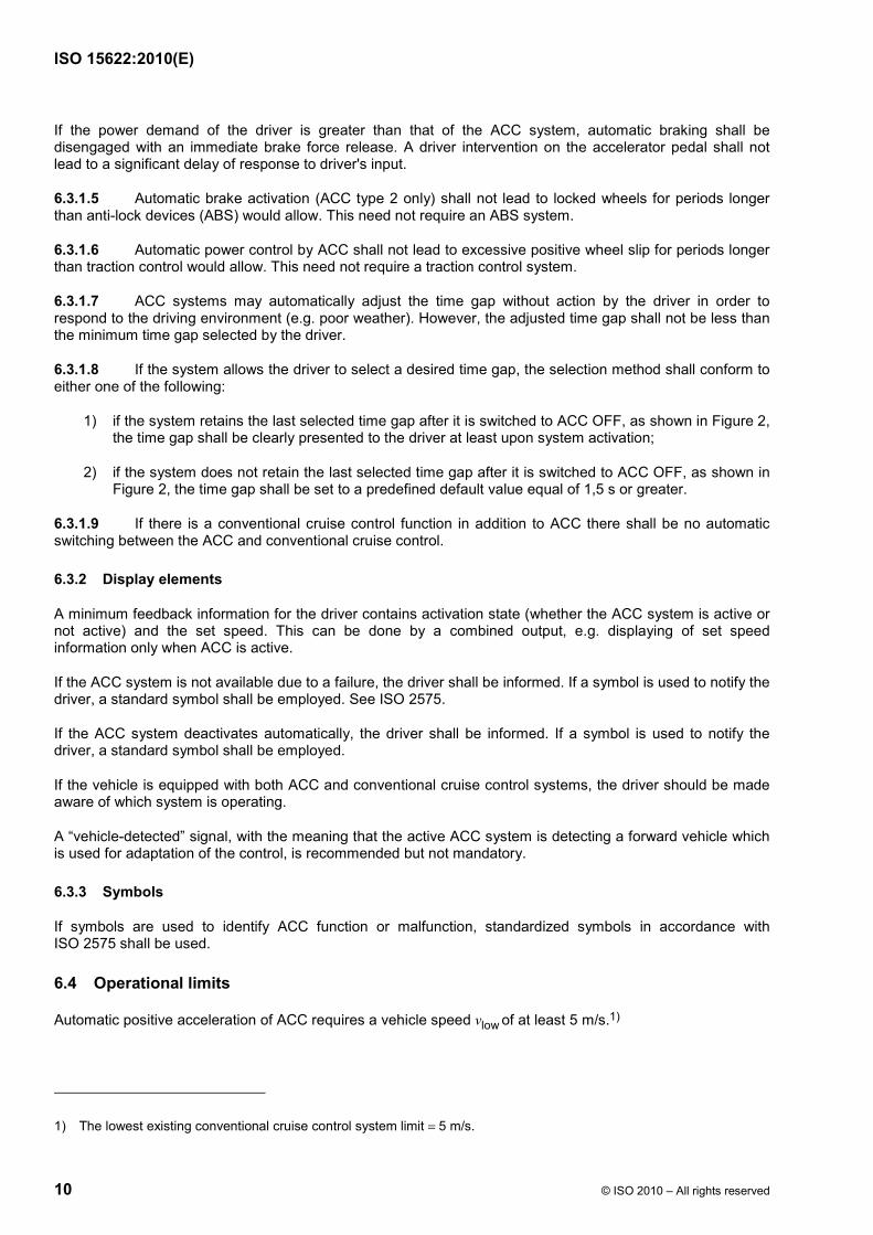
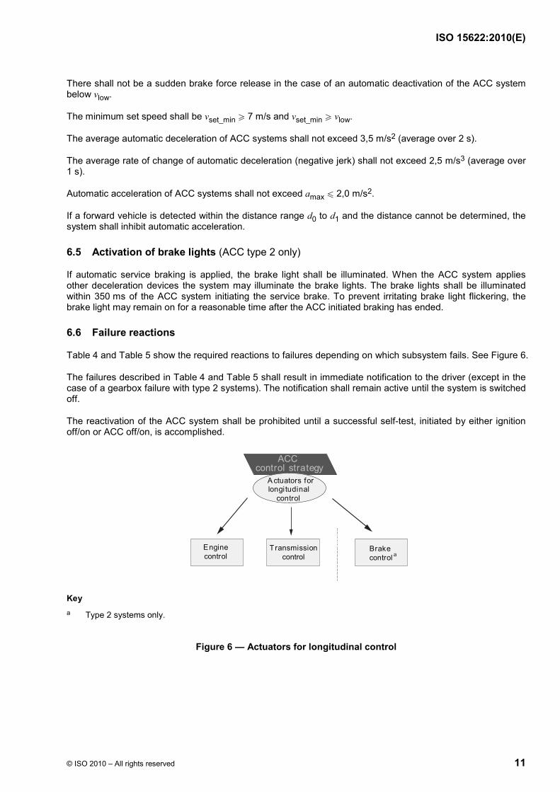
6.6 Failure reactions
Table 4 and Table 5 show the required reactions to failures depending on which subsystem fails. See Figure 6.
The failures described in Table 4 and Table 5 shall result in immediate notification to the driver (except in the case of a gearbox failure with type 2 systems). The notification shall remain active until the system is switched off.
The reactivation of the ACC system shall be prohibited until a successful self-test, initiated by either ignition off/on or ACC off/on, is accomplished.
ACCcontrol strategy
A ctuators forlongi tudinal control
Enginecontrol
Transmissioncontrol
Brake control a
Key a Type 2 systems only.
Figure 6 — Actuators for longitudinal control
ISO 15622:2010(E)
12 © ISO 2010 – All rights reserved
Table 4 — Failure reactions for ACC type 1
Failure occurs whilst ACC is applying: Failure in subsystem
Deceleration control Engine control
1 Engine ACC engine control mode shall be relinquished.
ACC engine control mode shall be relinquished.
2 Gearbox ACC control mode shall be relinquished. ACC engine control mode shall be relinquished.
3 Detecting and ranging sensor
Shall maintain same strategy as the time before fault at least as long as v > vlow.
The system shall be switched off immediately after driver intervention by brake or accelerator pedal or ACC off switch.
ACC engine control mode shall be relinquished.
4 ACC controller ACC control mode shall be relinquished. ACC control mode shall be relinquished.
Table 5 — Failure reactions for ACC type 2
Failure occurs whilst ACC is applying Failure in subsystem
Brake control Engine control
1 Engine Should maintain braking as required at least for the actual/current braking manoeuvre. ACC engine control shall be relinquished.
2 Brake systema
ACC control shall be relinquished. If the brake system failure is not total during an active brake manoeuvre, the system may finish the current braking manoeuvre before the ACC control is relinquished completely.
ACC engine control shall be relinquished.
3 Detecting and ranging sensor
Should initiate a controller strategy starting with the last valid braking command. Braking shall not be released suddenly in this case. The system shall be switched off immediately after driver intervention by brake or accelerator pedal or ACC off switch
ACC engine control shall be relinquished.
4 ACC controller ACC control shall be relinquished. ACC control shall be relinquished. a If a malfunction within the gear controller occurs, the brake will be able to handle the deceleration function.
7 Performance evaluation test methods
7.1 Environmental conditions
a) Test location shall be on a flat, dry asphalt or concrete surface.
b) Temperature range shall be between −20 °C and +40 °C.
c) Horizontal visibility range shall be greater than 1 km.
7.2 Test target specification
7.2.1 General
The test targets are specified for technologies used today. For other technologies, representative test targets shall be used.
ISO 15622:2010(E)
© ISO 2010 – All rights reserved 13
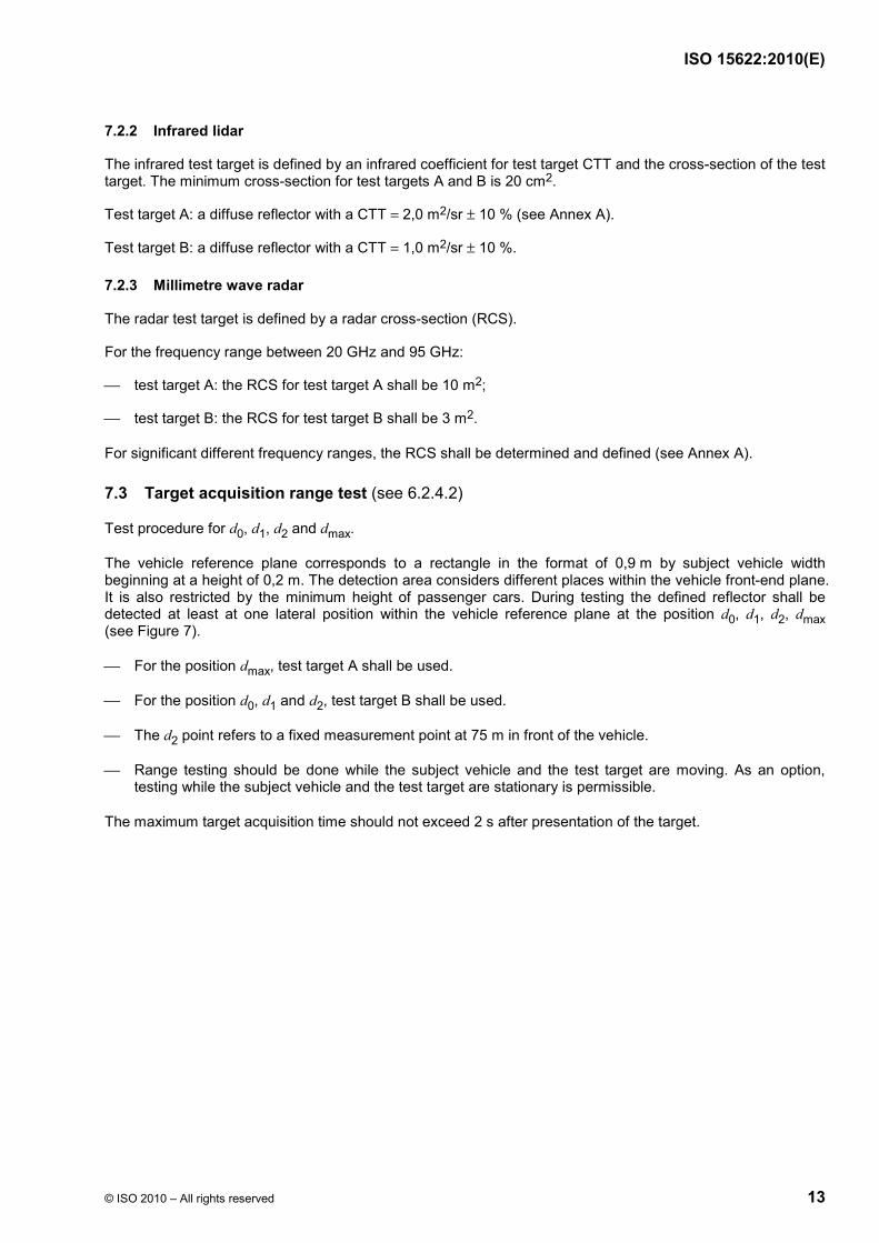
7.2.2 Infrared lidar
The infrared test target is defined by an infrared coefficient for test target CTT and the cross-section of the test target. The minimum cross-section for test targets A and B is 20 cm2.
Test target A: a diffuse reflector with a CTT = 2,0 m2/sr ± 10 % (see Annex A).
Test target B: a diffuse reflector with a CTT = 1,0 m2/sr ± 10 %.
7.2.3 Millimetre wave radar
The radar test target is defined by a radar cross-section (RCS).
For the frequency range between 20 GHz and 95 GHz:
⎯ test target A: the RCS for test target A shall be 10 m2;
⎯ test target B: the RCS for test target B shall be 3 m2.
For significant different frequency ranges, the RCS shall be determined and defined (see Annex A).
7.3 Target acquisition range test (see 6.2.4.2)
Test procedure for d0, d1, d2 and dmax.
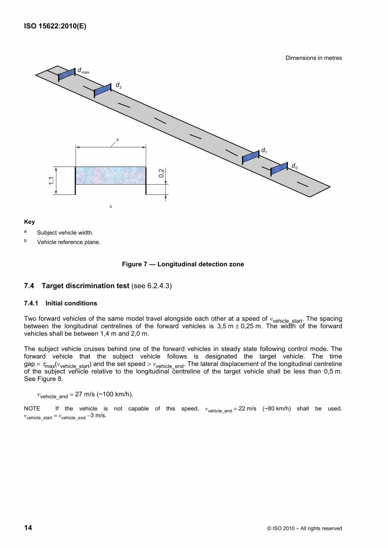
The vehicle reference plane corresponds to a rectangle in the format of 0,9 m by subject vehicle width beginning at a height of 0,2 m. The detection area considers different places within the vehicle front-end plane. It is also restricted by the minimum height of passenger cars. During testing the defined reflector shall be detected at least at one lateral position within the vehicle reference plane at the position d0, d1, d2, dmax (see Figure 7).
⎯ For the position dmax, test target A shall be used.
⎯ For the position d0, d1 and d2, test target B shall be used.
⎯ The d2 point refers to a fixed measurement point at 75 m in front of the vehicle.
⎯ Range testing should be done while the subject vehicle and the test target are moving. As an option, testing while the subject vehicle and the test target are stationary is permissible.
The maximum target acquisition time should not exceed 2 s after presentation of the target.
ISO 15622:2010(E)
14 © ISO 2010 – All rights reserved
Dimensions in metres
d max
d 1
d 0
b
d 2
a
1,1 0,
2
Key a Subject vehicle width. b Vehicle reference plane.
Figure 7 — Longitudinal detection zone
7.4 Target discrimination test (see 6.2.4.3)
7.4.1 Initial conditions
Two forward vehicles of the same model travel alongside each other at a speed of vvehicle_start. The spacing between the longitudinal centrelines of the forward vehicles is 3,5 m ± 0,25 m. The width of the forward vehicles shall be between 1,4 m and 2,0 m.
The subject vehicle cruises behind one of the forward vehicles in steady state following control mode. The forward vehicle that the subject vehicle follows is designated the target vehicle. The time gap = τmax(vvehicle_start) and the set speed > vvehicle_end. The lateral displacement of the longitudinal centreline of the subject vehicle relative to the longitudinal centreline of the target vehicle shall be less than 0,5 m. See Figure 8.
vvehicle_end = 27 m/s (~100 km/h).
NOTE If the vehicle is not capable of this speed, vvehicle_end = 22 m/s (~80 km/h) shall be used. vvehicle_start = vvehicle_end −3 m/s.

ISO 15622:2010(E)
© ISO 2010 – All rights reserved 15
Dimensions in metres
0,5
3,5
1 2
3 Key
1 subject vehicle
2 target vehicle
3 forward vehicle
Figure 8 — Discrimination test — Start conditions
7.4.2 Test procedure
The target vehicle accelerates to vvehicle_end. The test is successfully fulfilled if the subject vehicle passes the forward vehicle in the adjacent lane while under ACC control. See Figure 9.
1a
2a
3b
Key
1 subject vehicle
2 target vehicle
3 forward vehicle
a v = vvehicle_end b v = vvehicle_start
Figure 9 — Discrimination test — End conditions

ISO 15622:2010(E)
16 © ISO 2010 – All rights reserved
7.5 Curve capability test (see 6.2.4.4)
7.5.1 General
This test should take into consideration the road geometry prediction in combination with the field of view of the ACC system's sensor.
Different methods of road geometry prediction and headway sensing result in the need for a driving scenario.
7.5.2 Test field (classes II, III + IV)
Dimensions in metres
Figure 10 — Outline test track
The test track shall consist of either a circular track of constant radius or a sufficiently long segment of curve of constant radius. The radius should be within 80 % to 100 % of Rmin. The direction of travel on the track shall be both clockwise and anti-clockwise. There is no restriction concerning lane markings, guard rails, etc. See Figure 10.
⎯ For class II systems the tests shall be done for RminII = 500 m.
⎯ For class III systems the tests shall be done for RminIII = 250 m.
⎯ For class IV systems the tests shall be done for RminIV = 125 m.
7.5.3 Curve capability, target vehicle
The target vehicle shall be equipped with test target A as defined in 7.2. The test target shall be placed in the middle on the rear end of the vehicle at a height of 0,6 m ± 0,1 m above ground. The remaining exposed vehicle surface shall be concealed in such a way that the rear surface, with the test target removed, represents an RCS of no greater than 2 m2 or a reflectivity of no greater than 20 % of the test target.
7.5.4 Driving scenario
The subject vehicle follows the target vehicle along the same path (± 0,5 m lateral separation as measured from the centrelines of both vehicles) in following control mode. The two cars shall conform to the test start conditions as defined in Figure 8 (subject and target vehicle only) prior to the start of the test. Details of the test are shown in Table 6 and in Figure 11.
ISO 15622:2010(E)
© ISO 2010 – All rights reserved 17
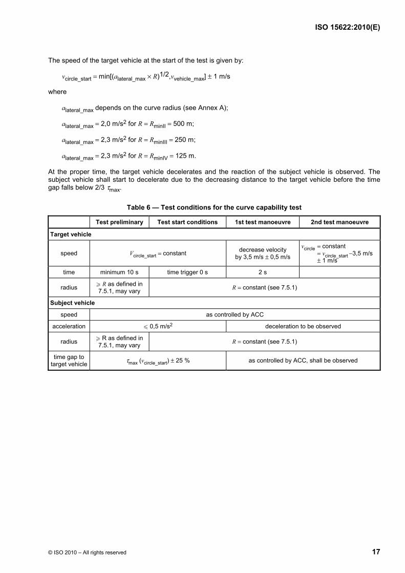
The speed of the target vehicle at the start of the test is given by:
vcircle_start = min[(alateral_max × R)1/2,vvehicle_max] ± 1 m/s
where
alateral_max depends on the curve radius (see Annex A);
alateral_max = 2,0 m/s2 for R = RminII = 500 m;
alateral_max = 2,3 m/s2 for R = RminIII = 250 m;
alateral_max = 2,3 m/s2 for R = RminIV = 125 m.
At the proper time, the target vehicle decelerates and the reaction of the subject vehicle is observed. The subject vehicle shall start to decelerate due to the decreasing distance to the target vehicle before the time gap falls below 2/3 τmax.
Table 6 — Test conditions for the curve capability test
Test preliminary Test start conditions 1st test manoeuvre 2nd test manoeuvre
Target vehicle
speed Vcircle_start = constant decrease velocity by 3,5 m/s ± 0,5 m/s
vcircle = constant = vcircle_start −3,5 m/s ± 1 m/s
time minimum 10 s time trigger 0 s 2 s
radius W R as defined in 7.5.1, may vary R = constant (see 7.5.1)
Subject vehicle
speed as controlled by ACC
acceleration u 0,5 m/s2 deceleration to be observed
radius W R as defined in 7.5.1, may vary R = constant (see 7.5.1)
time gap to target vehicle τmax (vcircle_start) ± 25 % as controlled by ACC, shall be observed

ISO 15622:2010(E)
18 © ISO 2010 – All rights reserved
Ra
b c
a R = constant. b Test starts when the subject vehicle is on a part of the track with constant radius and complies with the other test start conditions. c Test ends when the subject vehicle decelerates (positive result) or when the time gap falls below 2/3⎮max.
Figure 11 — Example of test track layout

ISO 15622:2010(E)
© ISO 2010 – All rights reserved 19
Annex A (normative)
Technical information
A.1 Lidar, coefficient of test target
A.1.1 Solid angle Ω
The solid angle, Ω, is the ratio of the irradiated portion of the surface of light to the square of the radius of the sphere. See Figure A.1.
2 0A
A
dΩ Ω= ×
where
Ω is the solid angle, in steradians;
A is the utilized area;
dA is the distance between source and projected area A;
Ω0 is the solid angle of the source, in steradians.
Figure A.1 — Solid angle
A.1.2 Radiated intensity I
The radiated intensity, I, is given by the radiated power, Φ, out of a radiation source, inside a solid angle, Ω.
refref
1
dI
dΦΩ
=
where
Iref is the radiated intensity in a given direction, out of the reflector, measured in front of the receiver surface, in watts per steradian;
ISO 15622:2010(E)
20 © ISO 2010 – All rights reserved
Φref is the radiated power, in watts;
Ω1 is the illuminated solid angle, in steradians.
A.1.3 Intensity of irradiation E
Intensity of irradiation is the ratio of the incident radiated power to the area of illuminated surface. E is the density by surface of the illumination.
tt
t
dE
dAΦ
=
where Et is the intensity of irradiation, in watts per square metre.
A.1.4 Coefficient for test target CTT
The test target is defined by a coefficient of a reflector, which represents the reflectivity of a dirty car without any retro-reflector.
ref
tCTT I
E=
where
CTT is the coefficient for test target, in square metres per steradian;
Iref is the radiated intensity in a given direction, out of the reflector, measured in front of the receiver surface, in watts per steradian;
Et is the intensity of irradiation, out of the transmitter, in watts per square metre.
The reflector (see Figure A.2) with the defined CTT shall have a spatial distribution of the reflection W 8 × 10⁻³ sr.

ISO 15622:2010(E)
© ISO 2010 – All rights reserved 21
2Aref
1
I [W/sr]
Key
1 receiver
2 reflector
Figure A.2 — Receiver scenario
Key
1 transmitter
2 reflector
Figure A.3 — Transmitter scenario
ISO 15622:2010(E)
22 © ISO 2010 – All rights reserved
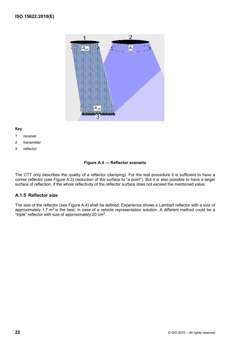
Key
1 receiver
2 transmitter
3 reflector
Figure A.4 — Reflector scenario
The CTT only describes the quality of a reflector (damping). For the test procedure it is sufficient to have a corner reflector (see Figure A.3) (reduction of the surface to “a point”). But it is also possible to have a larger surface of reflection, if the whole reflectivity of the reflector surface does not exceed the mentioned value.
A.1.5 Reflector size
The size of the reflector (see Figure A.4) shall be defined. Experience shows a Lambert reflector with a size of approximately 1,7 m2 is the best, in case of a vehicle representation solution. A different method could be a “triple” reflector with size of approximately 20 cm2.

ISO 15622:2010(E)
© ISO 2010 – All rights reserved 23
1
Key
1 reflector
Figure A.5 — Lambert reflector
The Lambert reflector reflects the whole energy inside a sphere area (see Figure A.5).
π 0 0IΦ Ω⊕ = × ×
where
Φ⊕ is the radiated power, in watts;
I0 is the radiated intensity, in watts per steradian;
Ω0 is the solid angle, in steradians.
A size of 1,7 m2 represents the cross-section of a small vehicle.
A.2 Definition of the RCS of a corner cube type test target
The test target is defined by a radar cross-section (RCS).
RCS = 10 ± 3 m2. For today's known frequencies (24 GHz, 60 GHz, 77 GHz, 90 GHz), 10 m2 represents at least 95 % of all vehicles driving on motorways. For significant different frequency ranges, investigations shall be carried out. Aspect of test target should be as shown in Figure A.6.
Figure A.6 — Corner cube reflector

ISO 15622:2010(E)
24 © ISO 2010 – All rights reserved
( )( )π 4
2
4RCS
3
L
λ
× ×=
×
where λ is the wavelength.
A.3 Following capability
Regarding d0, the 0,25 s value is based more on experience than on technical data. For values less than 0,25 s, the assumption is that the driver will intervene immediately so there is no need to avoid acceleration of ACC (for a scenario of cut-in at low speed). If the time gap is in the order of 0,5 s or more, there is no guarantee that the driver will intervene. So the system shall be able to detect and avoid acceleration.

ISO 15622:2010(E)
© ISO 2010 – All rights reserved 25
Bibliography
[1] ISO 6161, Personal eye-protectors — Filters and eye-protectors against laser radiation
[2] IEC 60825-1, Safety of laser products — Part 1: Equipment classification and requirements
[3] MITSCHKE, M., WALLENTOWITZ, H. and SCHWARTZ, E. Vermeiden querdynamisch kritischer Fahrzustände durch Fahrzustandsüberwachung (Avoidance of critical driving states in case of lateral acceleration by using driving state supervision), VDI, 91, 1991

ISO 15622:2010(E)
ICS 03.220.20; 35.240.60 Price based on 25 pages
© ISO 2010 – All rights reserved