Embed Size (px)
Citation preview

Questions? Call 800.GE.CARES (800.432.2737) or Visit our Website at: ge.com
READ CAREFULLY.
KEEP THESE INSTRUCTIONS.
Installation Over the RangeInstructions Microwave Oven
CVM2072
Read these instructions completely and carefully.
• IMPORTANT – Save these instructions for local inspector’s use.
• IMPORTANT – Observe all governing codes and ordinances.
• Note to Installer – Be sure to leave theseinstructions with the Consumer.
BEFORE YOU BEGIN• Note to Consumer – Keep these
instructions for future reference.• Skill level – Installation of this appliance requires
basic mechanical and electrical skills.• Proper installation is the responsibility of the installer. • Product failure due to improper installation is not
covered under the Warranty.
For a Spanish version of this manual, visit our Website at ge.com.Para consultar una version en español de este manual de instrucciones, visite nuestro sitiode internet ge.com.
2
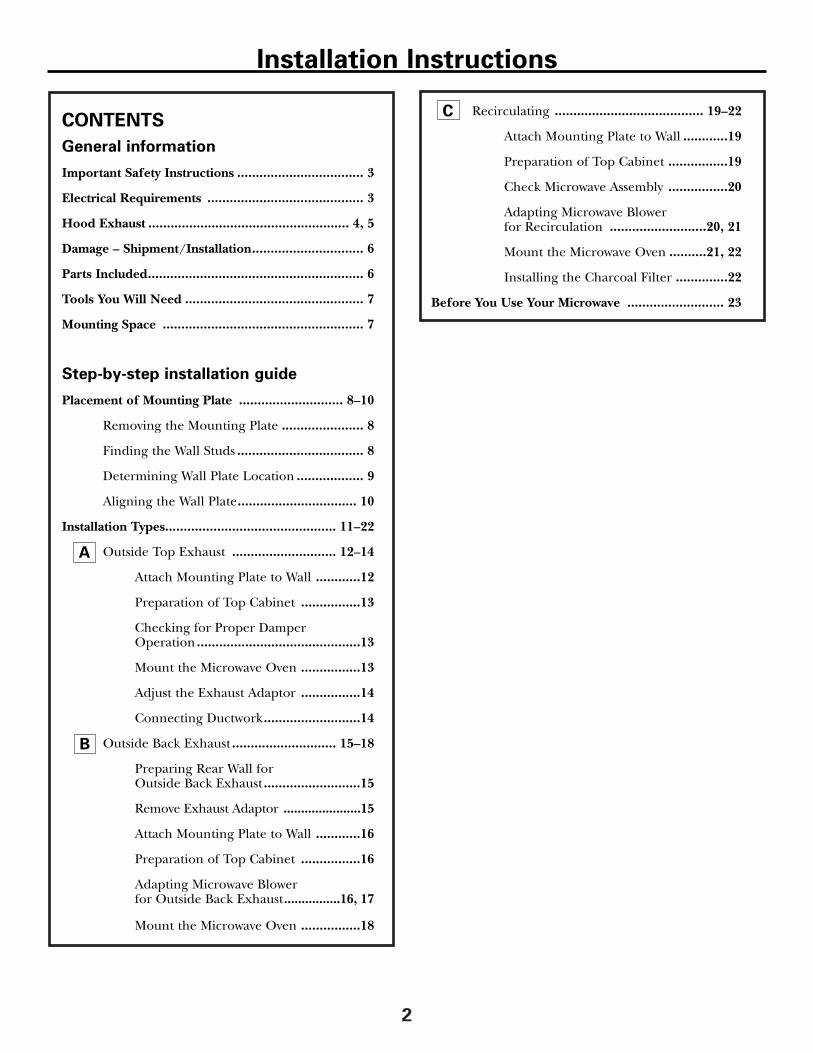
Recirculating ........................................ 19–22
Attach Mounting Plate to Wall ............19
Preparation of Top Cabinet ................19
Check Microwave Assembly ................20
Adapting Microwave Blower for Recirculation ..........................20, 21
Mount the Microwave Oven ..........21, 22
Installing the Charcoal Filter ..............22
Before You Use Your Microwave .......................... 23
CONTENTS
General information
Important Safety Instructions .................................. 3
Electrical Requirements .......................................... 3
Hood Exhaust ...................................................... 4, 5
Damage – Shipment/Installation.............................. 6
Parts Included.......................................................... 6
Tools You Will Need ................................................ 7
Mounting Space ...................................................... 7
Step-by-step installation guide
Placement of Mounting Plate ............................ 8–10
Removing the Mounting Plate ...................... 8
Finding the Wall Studs .................................. 8
Determining Wall Plate Location .................. 9
Aligning the Wall Plate................................ 10
Installation Types.............................................. 11–22
Outside Top Exhaust ............................ 12–14
Attach Mounting Plate to Wall ............12
Preparation of Top Cabinet ................13
Checking for Proper DamperOperation ............................................13
Mount the Microwave Oven ................13
Adjust the Exhaust Adaptor ................14
Connecting Ductwork..........................14
Outside Back Exhaust ............................ 15–18
Preparing Rear Wall for Outside Back Exhaust ..........................15
Remove Exhaust Adaptor ......................15
Attach Mounting Plate to Wall ............16
Preparation of Top Cabinet ................16
Adapting Microwave Blowerfor Outside Back Exhaust................16, 17
Mount the Microwave Oven ................18
A
B
C
Installation Instructions

This product requires a three-prong grounded outlet.The installer must perform a ground continuity check on the power outlet box before beginning the installation to insure that the outlet box is properlygrounded. If not properly grounded, or if the outlet box does not meet electrical requirements noted (under ELECTRICAL REQUIREMENTS), a qualifiedelectrician should be employed to correct anydeficiencies.
CAUTION: For personal safety, remove house fuse or open circuit breaker before beginning installation to avoid severe or fatal shock injury.
CAUTION: For personal safety, the mounting surface must be capable of supporting the cabinet load, in addition to the added weight of this 63–85 pound product, plus additional oven loads of up to 50 pounds or a total weight of 113–135 pounds.
CAUTION: For personal safety, this product cannot be installed in cabinet arrangements such as an island or a peninsula. It must be mounted to BOTH a top cabinet AND a wall.
NOTE: For easier installation and personal safety, it is recommended that two people install this product.IMPORTANT – PLEASE READ CAREFULLY. FOR PERSONAL SAFETY, THIS APPLIANCE MUST BE PROPERLY GROUNDED TO AVOID SEVERE OR FATAL SHOCK.
The power cord of this appliance is equipped with a three-prong (grounding) plug which mates with a standard three-prong (grounding) wall receptacle to minimize the possibility of electric shock hazard from this appliance.
You should have the wall receptacle and circuit checkedby a qualified electrician to make sure the receptacle isproperly grounded.
Where a standard two-prong wall receptacle is encountered, it is very important to have it replaced with a properly grounded three-prong wall receptacle,installed by a qualified electrician.
DO NOT, UNDER ANY CIRCUMSTANCES, CUT,DEFORM OR REMOVE ANY OF THE PRONGS FROM THE POWER CORD. DO NOT USE WITH AN EXTENSION CORD.
IMPORTANT SAFETY INSTRUCTIONS
3
ELECTRICALREQUIREMENTSProduct rating is 120 volts AC, 60 Hertz, 15 amps and1.58 kilowatts. This product must be connected to asupply circuit of the proper voltage and frequency.Wire size must conform to the requirements of theNational Electrical Code or the prevailing local code for this kilowatt rating. The power supply cord and plug should be brought to a separate 15- to 20- ampere branch circuit single groundedoutlet. The outlet box should be located in thecabinet above the microwave oven. The outlet boxand supply circuit should be installed by a qualifiedelectrician and conform to the National ElectricalCode or the prevailing local code.
Ensure properground existsbefore use
Installation Instructions

4
EQUIVALENT NUMBER EQUIVALENT
DUCT PIECES LENGTH x USED = LENGTH
Roof Cap 24 Ft. x (1) = 24 Ft.
12 Ft. Straight Duct 12 Ft. x (1) = 12 Ft.(6″ Round)
Rectangular-to-Round 5 Ft. x (1) = 5 Ft.Transition Adaptor*
Equivalent lengths of duct pieces are based on actual tests and reflect requirements for good venting performance with any vent hood.
Total Length = 41 Ft.
HOOD EXHAUST
The following chart describes an example of one possibleductwork installation.
NOTE: Read these next two pages only if you plan to vent your exhaust to theoutside. If you plan to recirculate the air back into the room, proceed to page 6.
OUTSIDE TOP EXHAUST (EXAMPLE ONLY)
NOTE: For back exhaust, care should be taken to align exhaust with space between studs, or wall should be preparedat the time it is constructed by leaving enough space between the wall studs to accommodate exhaust.
* IMPORTANT: If a rectangular-to-round transition adaptor is used, the bottom corners of the damper will have to be cut to fit, using the tin snips, in order to allow free movement of the damper.
The following chart describes an example of one possibleductwork installation.
Installation Instructions
OUTSIDE BACK EXHAUST (EXAMPLE ONLY)
EQUIVALENT NUMBER EQUIVALENT
DUCT PIECES LENGTH* x USED = LENGTH
Wall Cap 40 Ft. x (1) = 40 Ft.
3 Ft. Straight Duct 3 Ft. x (1) = 3 Ft.(31⁄4″ x 10″ Rectangular)
90° Elbow 10 Ft. x (2) = 20 Ft.
Equivalent lengths of duct pieces are based on actual tests and reflect requirements for good venting performance with any vent hood.
Total Length = 63 Ft.
EQUIVALENT NUMBER EQUIVALENT
DUCT PIECES LENGTH x USED = LENGTH
Rectangular-to-Round 5 Ft. x ( ) = Ft.Transition Adaptor*
Wall Cap 40 Ft. x ( ) = Ft.
90° Elbow 10 Ft. x ( ) = Ft.
45° Elbow 5 Ft. x ( ) = Ft.
90° Elbow 25 Ft. x ( ) = Ft.
45° Elbow 5 Ft. x ( ) = Ft.
Roof Cap 24 Ft. x ( ) = Ft.
Straight Duct 6″ Round or 1 Ft. x ( ) = Ft.31⁄4″ x 10″ Rectangular
Total Ductwork = Ft.
Equivalent lengths of duct pieces are based on actual tests and reflect requirements for good venting performance with any vent hood.
* IMPORTANT: If a rectangular-to-round transitionadaptor is used, the bottom corners of the damperwill have to be cut to fit, using the tin snips, in orderto allow free movement of the damper.
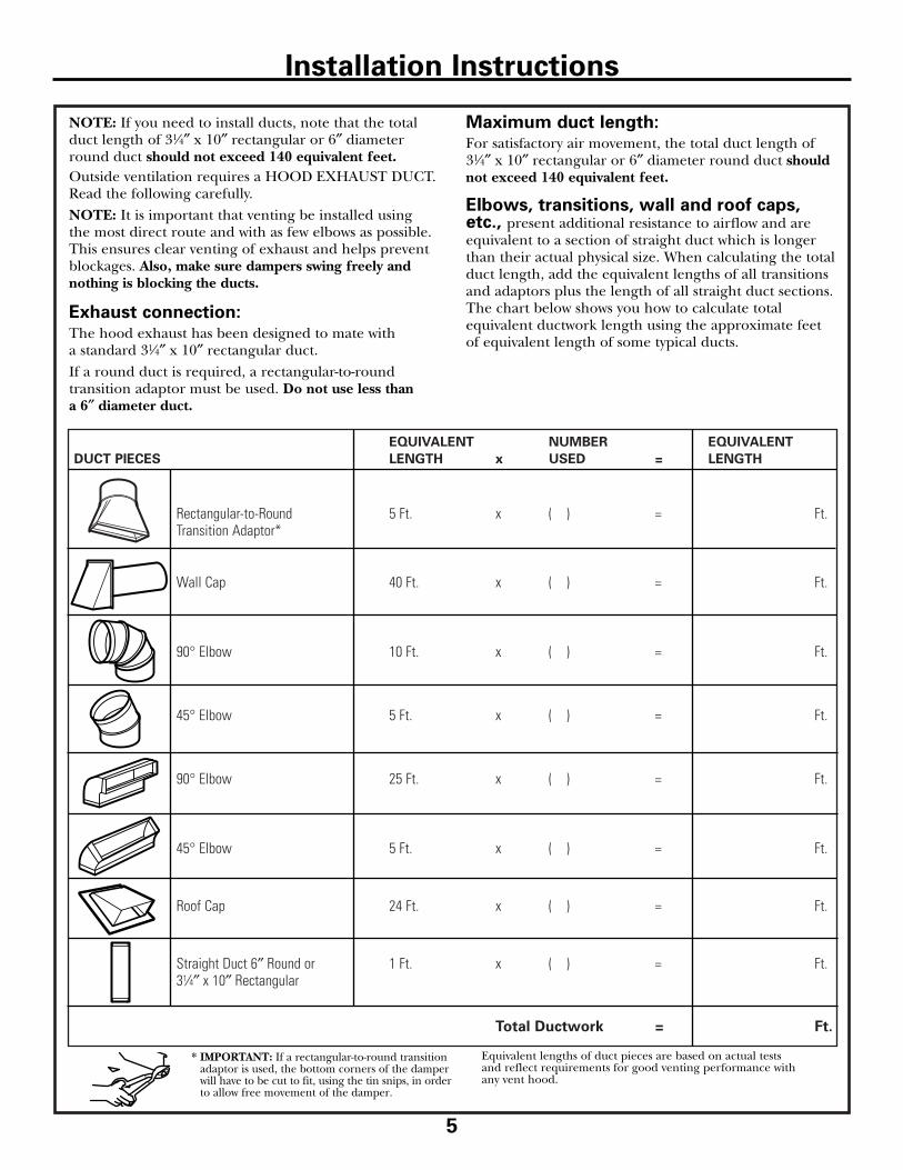
NOTE: If you need to install ducts, note that the totalduct length of 31⁄4″ x 10″ rectangular or 6″ diameterround duct should not exceed 140 equivalent feet.Outside ventilation requires a HOOD EXHAUST DUCT.Read the following carefully.NOTE: It is important that venting be installed using the most direct route and with as few elbows as possible. This ensures clear venting of exhaust and helps preventblockages. Also, make sure dampers swing freely andnothing is blocking the ducts.
Exhaust connection: The hood exhaust has been designed to mate with a standard 31⁄4″ x 10″ rectangular duct.If a round duct is required, a rectangular-to-round transition adaptor must be used. Do not use less than a 6″ diameter duct.
Maximum duct length: For satisfactory air movement, the total duct length of 31⁄4″ x 10″ rectangular or 6″ diameter round duct shouldnot exceed 140 equivalent feet.
Elbows, transitions, wall and roof caps,etc., present additional resistance to airflow and areequivalent to a section of straight duct which is longerthan their actual physical size. When calculating the totalduct length, add the equivalent lengths of all transitionsand adaptors plus the length of all straight duct sections.The chart below shows you how to calculate totalequivalent ductwork length using the approximate feetof equivalent length of some typical ducts.
5
Installation Instructions
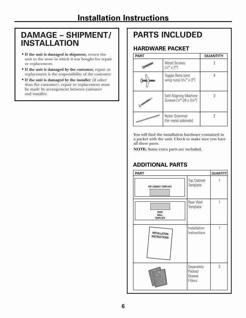
PART QUANTITY
Top Cabinet 1Template
Rear Wall 1Template
Installation 1Instructions
Separately 2Packed Grease Filters
6
PART QUANTITY
Wood Screws 2(1⁄4″ x 2″)
Toggle Bolts (and 4 wing nuts) (3⁄16″ x 3″)
Self-Aligning Machine 3 Screws (1⁄4″-28 x 31⁄4″)
Nylon Grommet 2(for metal cabinets)
• If the unit is damaged in shipment, return theunit to the store in which it was bought for repairor replacement.
• If the unit is damaged by the customer, repair or replacement is the responsibility of the customer.
• If the unit is damaged by the installer (if otherthan the customer), repair or replacement mustbe made by arrangement between customer and installer.
DAMAGE – SHIPMENT/INSTALLATION
PARTS INCLUDED
You will find the installation hardware contained ina packet with the unit. Check to make sure you haveall these parts.NOTE: Some extra parts are included.
HARDWARE PACKET
ADDITIONAL PARTS
Installation Instructions
7
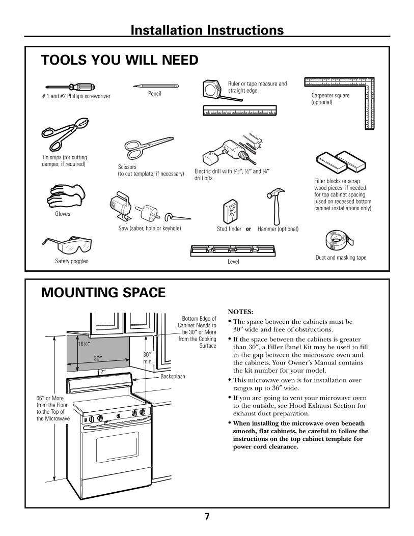
TOOLS YOU WILL NEED
# 1 and #2 Phillips screwdriver Pencil
Ruler or tape measure andstraight edge
Carpenter square(optional)
Tin snips (for cuttingdamper, if required)
Electric drill with 3⁄16″, 1⁄2″ and 5⁄8″drill bits
Hammer (optional)Stud finder or
Filler blocks or scrapwood pieces, if needed for top cabinet spacing(used on recessed bottomcabinet installations only)
Gloves
Saw (saber, hole or keyhole)
LevelDuct and masking tape
MOUNTING SPACE
NOTES:• The space between the cabinets must be
30″ wide and free of obstructions. • If the space between the cabinets is greater
than 30″, a Filler Panel Kit may be used to fill in the gap between the microwave oven and the cabinets. Your Owner’s Manual contains the kit number for your model.
• This microwave oven is for installation overranges up to 36″ wide.
• If you are going to vent your microwave oven to the outside, see Hood Exhaust Section forexhaust duct preparation.
• When installing the microwave oven beneathsmooth, flat cabinets, be careful to follow theinstructions on the top cabinet template for power cord clearance.
Backsplash
66″ or Morefrom the Floorto the Top ofthe Microwave
30″
2″
30″min.
161⁄2″
Bottom Edge ofCabinet Needs to
be 30″ or Morefrom the Cooking
Surface
Installation Instructions
Scissors (to cut template, if necessary)
Safety goggles
8
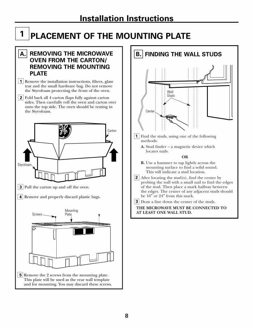
Find the studs, using one of the following methods:A. Stud finder – a magnetic device which
locates nails.OR
B. Use a hammer to tap lightly across the mounting surface to find a solid sound. This will indicate a stud location.
After locating the stud(s), find the center by probing the wall with a small nail to find the edgesof the stud. Then place a mark halfway betweenthe edges. The center of any adjacent studs shouldbe 16″ or 24″ from this mark.Draw a line down the center of the studs.
THE MICROWAVE MUST BE CONNECTED TO AT LEAST ONE WALL STUD.
1
Remove the installation instructions, filters, glasstray and the small hardware bag. Do not removethe Styrofoam protecting the front of the oven.
Fold back all 4 carton flaps fully against cartonsides. Then carefully roll the oven and carton overonto the top side. The oven should be resting inthe Styrofoam.
REMOVING THE MICROWAVEOVEN FROM THE CARTON/REMOVING THE MOUNTING PLATE
FINDING THE WALL STUDSB.A.
2
PLACEMENT OF THE MOUNTING PLATE1
Wall Studs
Center
3
Carton
Pull the carton up and off the oven.
Remove the 2 screws from the mounting plate.This plate will be used as the rear wall templateand for mounting. You may discard these screws.
MountingPlateScrews
2
Styrofoam
Installation Instructions
3
5
Remove and properly discard plastic bags.4
1
9
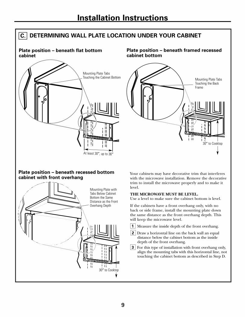
DETERMINING WALL PLATE LOCATION UNDER YOUR CABINETC.
Your cabinets may have decorative trim that interfereswith the microwave installation. Remove the decorativetrim to install the microwave properly and to make itlevel.
THE MICROWAVE MUST BE LEVEL.Use a level to make sure the cabinet bottom is level.
If the cabinets have a front overhang only, with no back or side frame, install the mounting plate down the same distance as the front overhang depth. This will keep the microwave level.
Measure the inside depth of the front overhang.
Draw a horizontal line on the back wall an equal distance below the cabinet bottom as the insidedepth of the front overhang.For this type of installation with front overhang only,align the mounting tabs with this horizontal line, nottouching the cabinet bottom as described in Step D.
Plate position – beneath flat bottom cabinet
Plate position – beneath recessed bottomcabinet with front overhang
Mounting Plate Tabs Touching the Cabinet Bottom
Mounting Plate withTabs Below CabinetBottom the SameDistance as the FrontOverhang Depth
At least 30″, up to 36″
Plate position – beneath framed recessed cabinet bottom
Mounting Plate TabsTouching the BackFrame
Installation Instructions
30″ to Cooktop
30″ to Cooktop
1
2
3
10
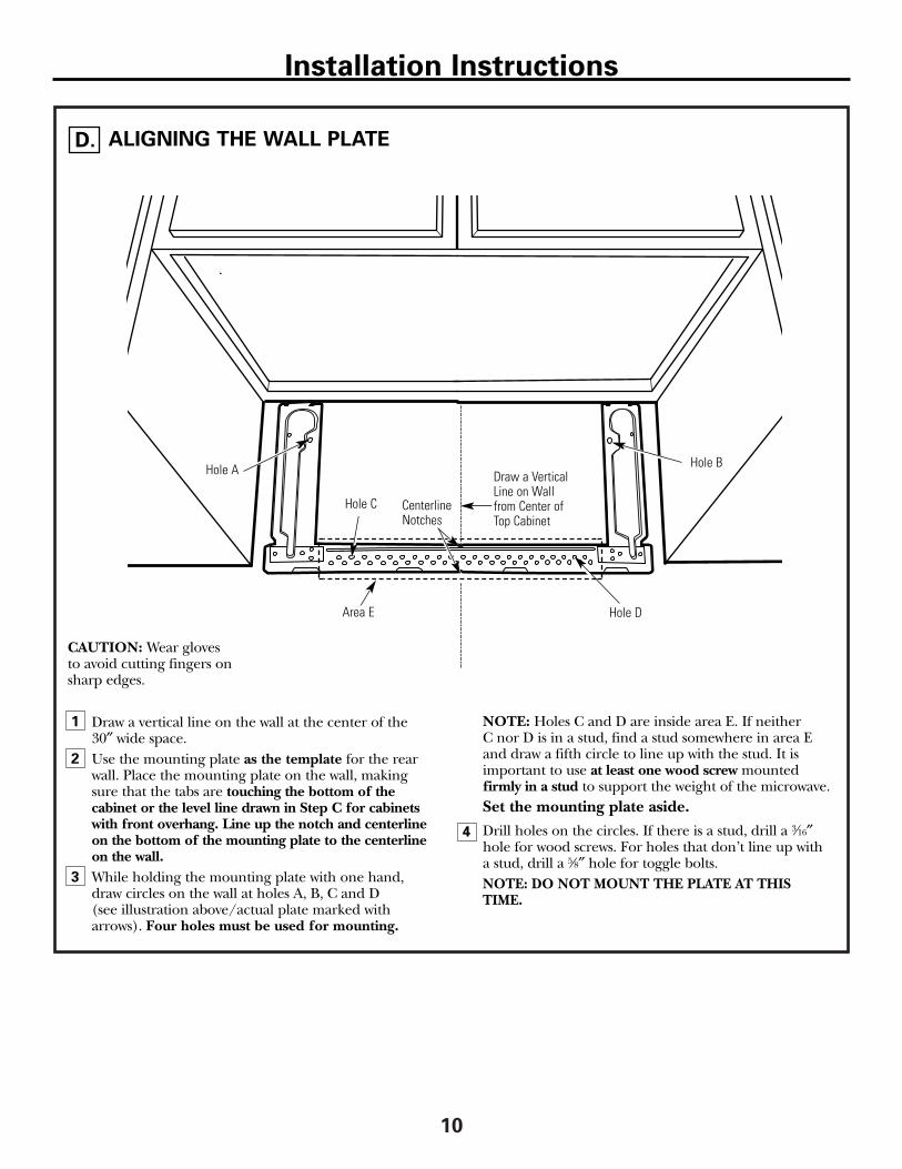
ALIGNING THE WALL PLATE
Draw a vertical line on the wall at the center of the 30″ wide space.Use the mounting plate as the template for the rearwall. Place the mounting plate on the wall, making sure that the tabs are touching the bottom of the cabinet or the level line drawn in Step C for cabinetswith front overhang. Line up the notch and centerlineon the bottom of the mounting plate to the centerlineon the wall.While holding the mounting plate with one hand, draw circles on the wall at holes A, B, C and D (see illustration above/actual plate marked witharrows). Four holes must be used for mounting.
NOTE: Holes C and D are inside area E. If neither C nor D is in a stud, find a stud somewhere in area Eand draw a fifth circle to line up with the stud. It isimportant to use at least one wood screw mounted firmly in a stud to support the weight of the microwave.Set the mounting plate aside.Drill holes on the circles. If there is a stud, drill a 3⁄16″hole for wood screws. For holes that don’t line up witha stud, drill a 5⁄8″ hole for toggle bolts.NOTE: DO NOT MOUNT THE PLATE AT THISTIME.
1
2
3
4
Draw a VerticalLine on Wallfrom Center ofTop Cabinet
Area E
Hole A Hole B
Hole D
Hole C
D.
Installation Instructions
CAUTION: Wear glovesto avoid cutting fingers onsharp edges.
CenterlineNotches

A
INSTALLATION TYPES (Choose A, B or C)
This microwave oven is designed for adaptation to the following three types of ventilation: A. Outside Top Exhaust (Vertical Duct)B. Outside Back Exhaust (Horizontal Duct)C.Recirculating (Non-Vented Ductless)
NOTE: This microwave is shipped assembled for OutsideTop Exhaust (except for non-vented models). Select thetype of ventilation required for your installation and proceed to that section.
OUTSIDE TOP EXHAUST(VERTICAL DUCT)
OUTSIDE BACK EXHAUST(HORIZONTAL DUCT)
RECIRCULATING(NON-VENTED DUCTLESS)
See page 12 See page 15
See page 19
A Charcoal Filter AccessoryKit is required for the non-vented exhaust. (See your Owner’s Manual for the kit number.)
Adaptor in Place forOutside Top Exhaust
Installation Instructions
2
B
C
11
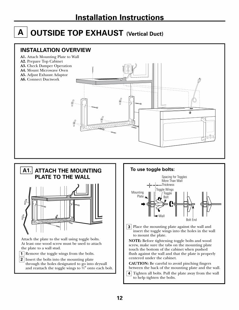
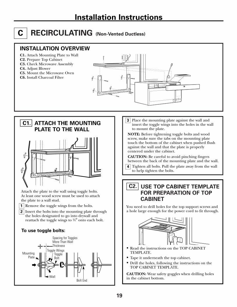
Place the mounting plate against the wall andinsert the toggle wings into the holes in the wall to mount the plate.
NOTE: Before tightening toggle bolts and woodscrew, make sure the tabs on the mounting platetouch the bottom of the cabinet when pushed flush against the wall and that the plate is properlycentered under the cabinet.CAUTION: Be careful to avoid pinching fingersbetween the back of the mounting plate and the wall.
Tighten all bolts. Pull the plate away from the wallto help tighten the bolts.
3
A
4
ATTACH THE MOUNTINGPLATE TO THE WALL
A1.
12
OUTSIDE TOP EXHAUST (Vertical Duct)
Attach the plate to the wall using toggle bolts. At least one wood screw must be used to attach the plate to a wall stud.
Remove the toggle wings from the bolts.
Insert the bolts into the mounting plate through the holes designated to go into drywalland reattach the toggle wings to 3⁄4″ onto each bolt.
1
INSTALLATION OVERVIEWA1. Attach Mounting Plate to WallA2. Prepare Top CabinetA3. Check Damper OperationA4. Mount Microwave OvenA5. Adjust Exhaust AdaptorA6. Connect Ductwork
Wall
MountingPlate
Spacing for TogglesMore Than WallThickness
Bolt End
Toggle Bolt
Toggle Wings
To use toggle bolts:
Installation Instructions
2
13
3
MOUNT THE MICROWAVEOVEN
A4.
CHECK FOR PROPERDAMPER OPERATION
A3.
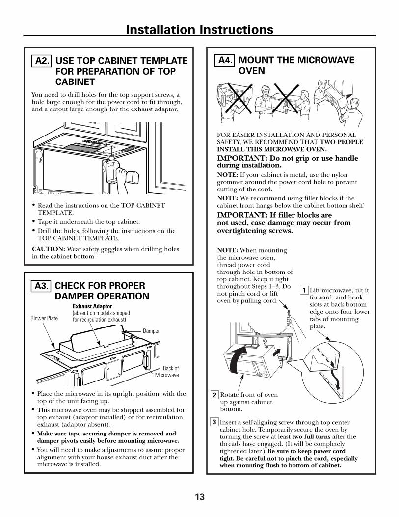
USE TOP CABINET TEMPLATEFOR PREPARATION OF TOPCABINET
You need to drill holes for the top support screws, ahole large enough for the power cord to fit through,and a cutout large enough for the exhaust adaptor.
A2.
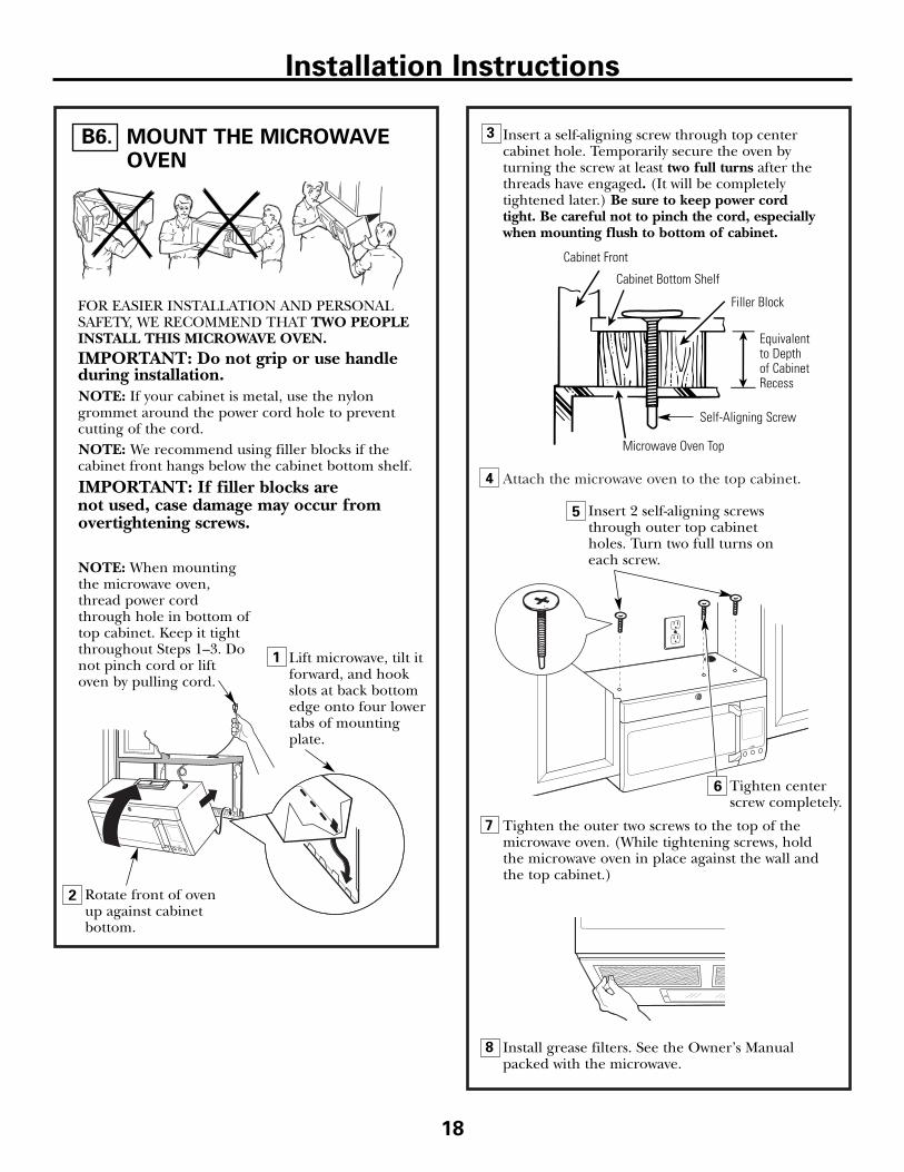
FOR EASIER INSTALLATION AND PERSONALSAFETY, WE RECOMMEND THAT TWO PEOPLEINSTALL THIS MICROWAVE OVEN. IMPORTANT: Do not grip or use handleduring installation.NOTE: If your cabinet is metal, use the nylon grommet around the power cord hole to prevent cutting of the cord.NOTE: We recommend using filler blocks if the cabinet front hangs below the cabinet bottom shelf.
IMPORTANT: If filler blocks are not used, case damage may occur from overtightening screws.
Insert a self-aligning screw through top center cabinet hole. Temporarily secure the oven by turning the screw at least two full turns after thethreads have engaged. (It will be completelytightened later.) Be sure to keep power cordtight. Be careful not to pinch the cord, especiallywhen mounting flush to bottom of cabinet.
NOTE: When mountingthe microwave oven,thread power cordthrough hole in bottom oftop cabinet. Keep it tightthroughout Steps 1–3. Donot pinch cord or liftoven by pulling cord.
Lift microwave, tilt itforward, and hookslots at back bottomedge onto four lowertabs of mountingplate.
Exhaust Adaptor(absent on models shippedfor recirculation exhaust)Blower Plate
Damper
Back ofMicrowave
• Read the instructions on the TOP CABINET TEMPLATE.
• Tape it underneath the top cabinet.• Drill the holes, following the instructions on the
TOP CABINET TEMPLATE.
CAUTION: Wear safety goggles when drilling holesin the cabinet bottom.
Installation Instructions
• Place the microwave in its upright position, with thetop of the unit facing up.
• This microwave oven may be shipped assembled fortop exhaust (adaptor installed) or for recirculationexhaust (adaptor absent).
• Make sure tape securing damper is removed anddamper pivots easily before mounting microwave.
• You will need to make adjustments to assure properalignment with your house exhaust duct after themicrowave is installed.
1
2 Rotate front of ovenup against cabinet bottom.

14
4 Attach the microwave oven to the top cabinet.
8
7
6
Cabinet Front
Cabinet Bottom Shelf
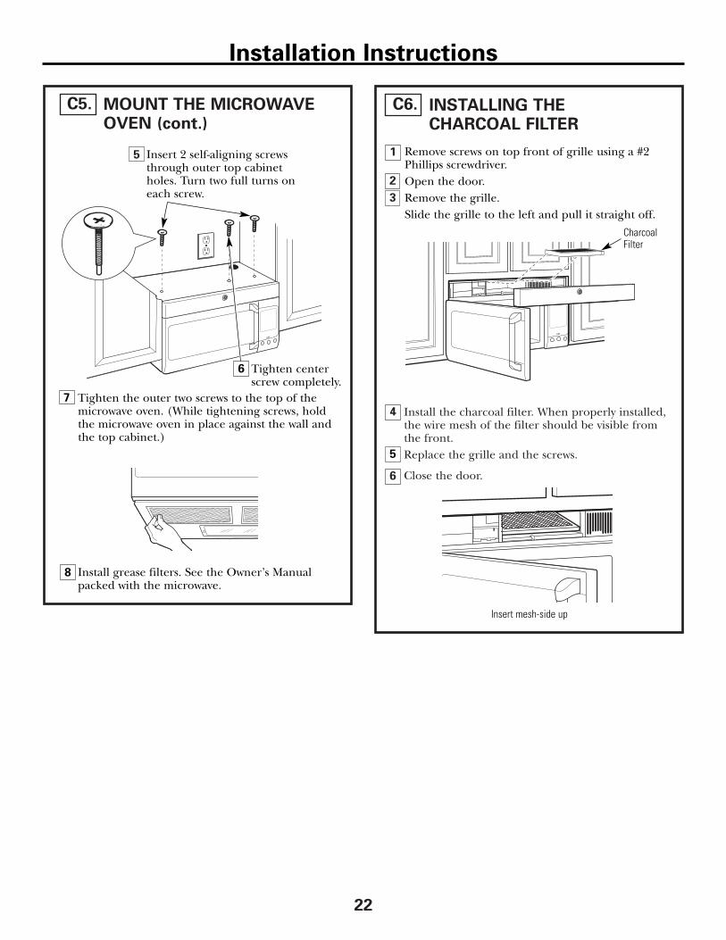
Tighten the outer two screws to the top of themicrowave oven. (While tightening screws, holdthe microwave oven in place against the wall andthe top cabinet.)
Filler Block
Microwave Oven Top
Equivalent to Depth of CabinetRecess
Insert 2 self-aligning screwsthrough outer top cabinetholes. Turn two full turns oneach screw.
Tighten center screw completely.
Install grease filters. See the Owner’s Manualpacked with the microwave.
Installation Instructions
ADJUST THE EXHAUSTADAPTOR
A5.
Open the top cabinet and adjust the exhaust adaptorto connect to the house duct.
Back of Microwave
For Front-to-Back or Side-to-Side Adjustment,Slide the Exhaust Adaptoras Needed
Blower PlateDamper
CONNECTING DUCTWORK
1
2
Extend the house duct down to connect tothe exhaust adaptor. Seal exhaust duct joints using duct tape.
A6.
House Duct
Self-Aligning Screw
5
MOUNT THE MICROWAVEOVEN (cont.)
A4.
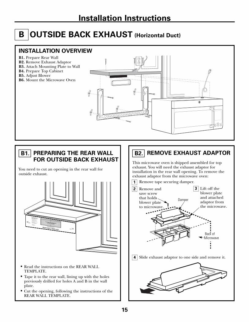
This microwave oven is shipped assembled for topexhaust. You will need the exhaust adaptor forinstallation in the rear wall opening. To remove theexhaust adaptor from the microwave oven:
Remove tape securing damper.
2
OUTSIDE BACK EXHAUST (Horizontal Duct)
Lift off theblower plateand attachedadaptor fromthe microwave.
INSTALLATION OVERVIEWB1. Prepare Rear WallB2. Remove Exhaust AdaptorB3. Attach Mounting Plate to WallB4. Prepare Top CabinetB5. Adjust BlowerB6. Mount the Microwave Oven
Slide exhaust adaptor to one side and remove it.
Back ofMicrowave
Remove andsave screwthat holdsblower plateto microwave.
Installation Instructions
B
15
3
4
Damper
1
PREPARING THE REAR WALL FOR OUTSIDE BACK EXHAUST
B1.
You need to cut an opening in the rear wall foroutside exhaust.
• Read the instructions on the REAR WALLTEMPLATE.
• Tape it to the rear wall, lining up with the holespreviously drilled for holes A and B in the wallplate.
• Cut the opening, following the instructions of theREAR WALL TEMPLATE.
REMOVE EXHAUST ADAPTOR B2.
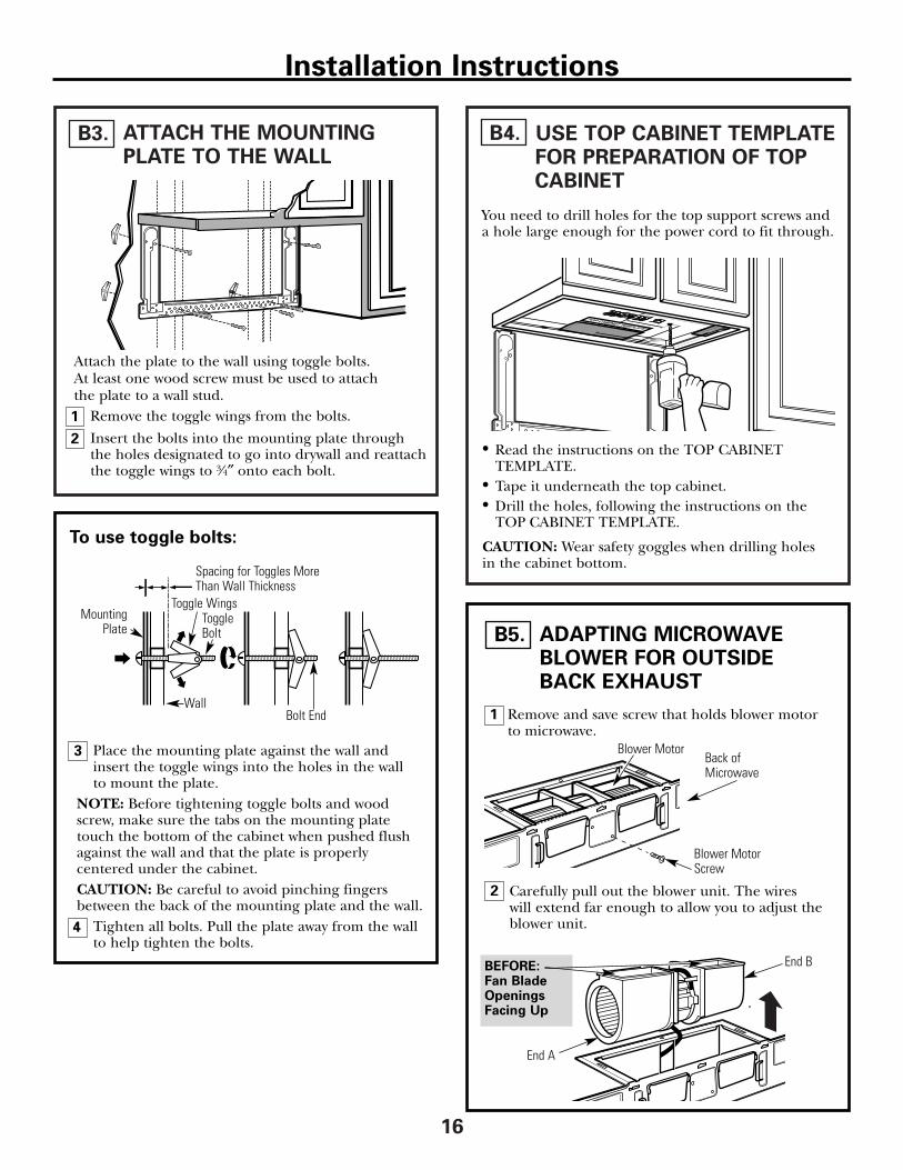
ATTACH THE MOUNTINGPLATE TO THE WALL
B3.
16
USE TOP CABINET TEMPLATEFOR PREPARATION OF TOP CABINET
B4.
• Read the instructions on the TOP CABINETTEMPLATE.
• Tape it underneath the top cabinet.• Drill the holes, following the instructions on the
TOP CABINET TEMPLATE.
CAUTION: Wear safety goggles when drilling holes in the cabinet bottom.
Wall
MountingPlate
Spacing for Toggles MoreThan Wall Thickness
Toggle Bolt
Toggle Wings
To use toggle bolts:
Bolt End
Installation Instructions
You need to drill holes for the top support screws anda hole large enough for the power cord to fit through.
Attach the plate to the wall using toggle bolts. At least one wood screw must be used to attach the plate to a wall stud.
Remove the toggle wings from the bolts.
Insert the bolts into the mounting plate throughthe holes designated to go into drywall and reattachthe toggle wings to 3⁄4″ onto each bolt.
1
2
Place the mounting plate against the wall andinsert the toggle wings into the holes in the wall to mount the plate.
NOTE: Before tightening toggle bolts and woodscrew, make sure the tabs on the mounting platetouch the bottom of the cabinet when pushed flushagainst the wall and that the plate is properlycentered under the cabinet.CAUTION: Be careful to avoid pinching fingersbetween the back of the mounting plate and the wall.
Tighten all bolts. Pull the plate away from the wallto help tighten the bolts.
3
4
BEFORE: Fan BladeOpeningsFacing Up
2
1 Remove and save screw that holds blower motorto microwave.
ADAPTING MICROWAVEBLOWER FOR OUTSIDEBACK EXHAUST
B5.
End B
End A
Carefully pull out the blower unit. The wires will extend far enough to allow you to adjust theblower unit.
Back ofMicrowave
Blower Motor
Blower MotorScrew
10
9
8
5
4
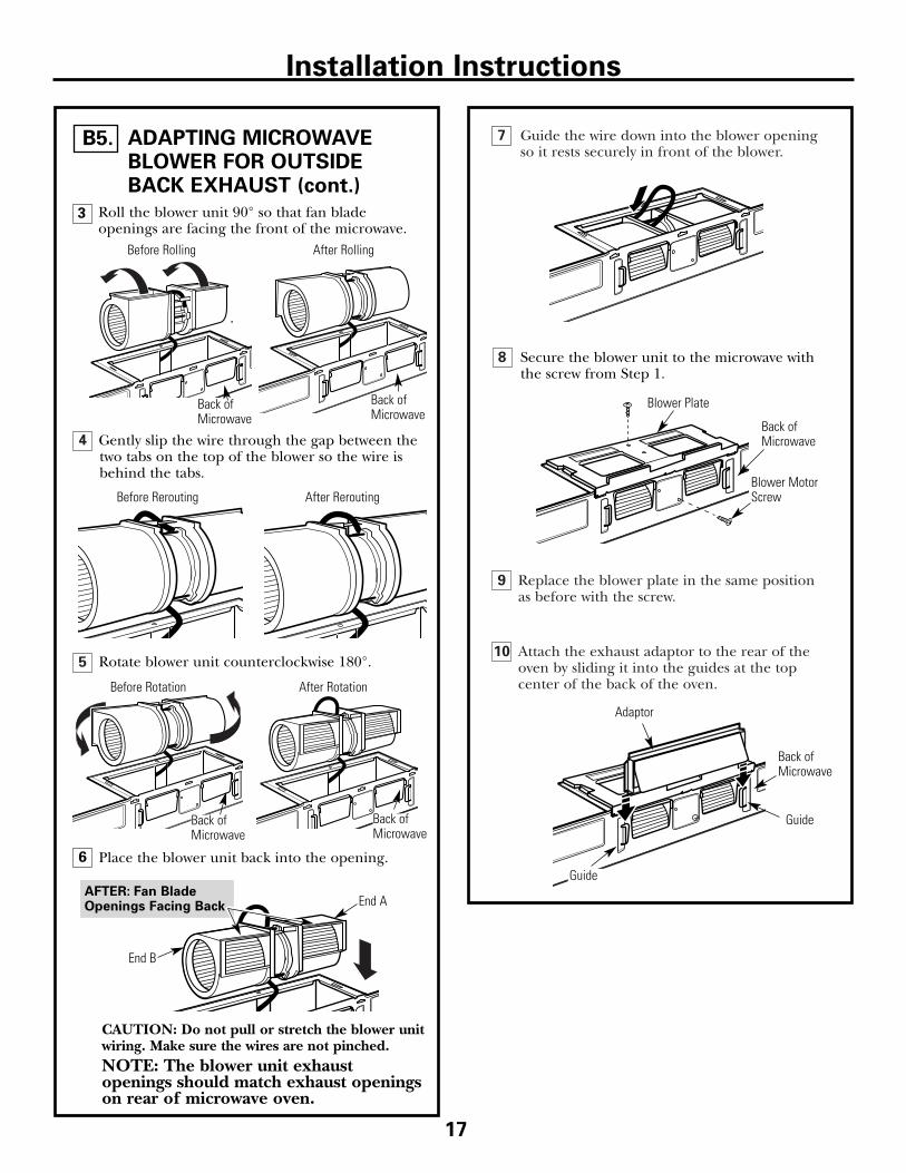
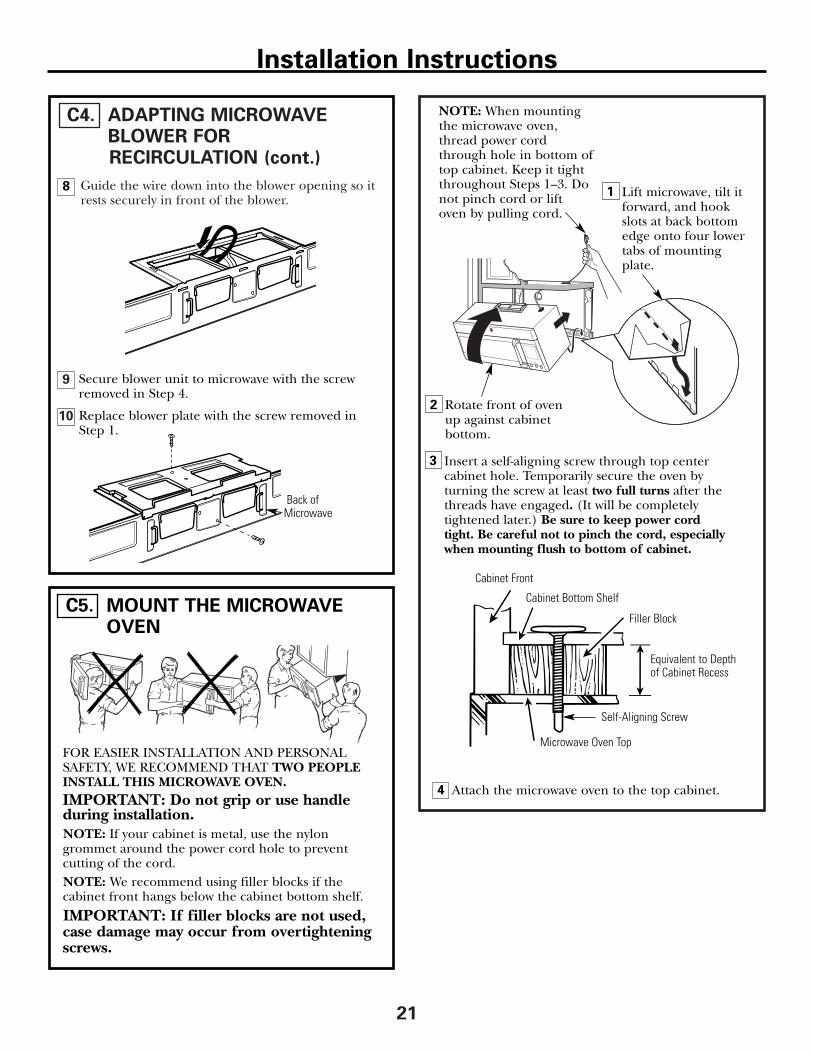
7 Guide the wire down into the blower openingso it rests securely in front of the blower.
Replace the blower plate in the same positionas before with the screw.
Attach the exhaust adaptor to the rear of theoven by sliding it into the guides at the topcenter of the back of the oven.
AFTER: Fan BladeOpenings Facing Back
6 Place the blower unit back into the opening.
Roll the blower unit 90° so that fan bladeopenings are facing the front of the microwave.
ADAPTING MICROWAVEBLOWER FOR OUTSIDEBACK EXHAUST (cont.)
B5.
17
Rotate blower unit counterclockwise 180°.
Before Rotation After Rotation
Gently slip the wire through the gap between thetwo tabs on the top of the blower so the wire isbehind the tabs.
Before Rerouting After Rerouting
Back ofMicrowave
Back ofMicrowave
Blower Plate
Blower MotorScrew
Secure the blower unit to the microwave withthe screw from Step 1.
Before Rolling After Rolling
Back ofMicrowave
End A
End B
Back ofMicrowave
Back ofMicrowave
CAUTION: Do not pull or stretch the blower unitwiring. Make sure the wires are not pinched.NOTE: The blower unit exhaustopenings should match exhaust openingson rear of microwave oven.
Installation Instructions
Guide
Guide
Adaptor
Back of Microwave
3
Attach the microwave oven to the top cabinet.
18
Installation Instructions
3MOUNT THE MICROWAVEOVEN
B6.
FOR EASIER INSTALLATION AND PERSONALSAFETY, WE RECOMMEND THAT TWO PEOPLEINSTALL THIS MICROWAVE OVEN. IMPORTANT: Do not grip or use handleduring installation.NOTE: If your cabinet is metal, use the nylongrommet around the power cord hole to preventcutting of the cord.NOTE: We recommend using filler blocks if the cabinet front hangs below the cabinet bottom shelf.
IMPORTANT: If filler blocks are not used, case damage may occur from overtightening screws.
Insert a self-aligning screw through top center cabinet hole. Temporarily secure the oven by turning the screw at least two full turns after thethreads have engaged. (It will be completelytightened later.) Be sure to keep power cordtight. Be careful not to pinch the cord, especiallywhen mounting flush to bottom of cabinet.
NOTE: When mountingthe microwave oven,thread power cordthrough hole in bottom oftop cabinet. Keep it tightthroughout Steps 1–3. Donot pinch cord or liftoven by pulling cord.
Lift microwave, tilt itforward, and hookslots at back bottomedge onto four lowertabs of mountingplate.
8
7
5
Cabinet Front
Cabinet Bottom Shelf
Tighten the outer two screws to the top of themicrowave oven. (While tightening screws, holdthe microwave oven in place against the wall andthe top cabinet.)
Filler Block
Microwave Oven Top
Equivalent to Depth of CabinetRecess
Insert 2 self-aligning screwsthrough outer top cabinetholes. Turn two full turns oneach screw.
Tighten center screw completely.
Install grease filters. See the Owner’s Manualpacked with the microwave.
Self-Aligning Screw
6
4
1
2 Rotate front of ovenup against cabinet bottom.
USE TOP CABINET TEMPLATEFOR PREPARATION OF TOP CABINET
C2.
19
RECIRCULATING (Non-Vented Ductless)
INSTALLATION OVERVIEWC1. Attach Mounting Plate to WallC2. Prepare Top Cabinet C3. Check Microwave AssemblyC4. Adjust BlowerC5. Mount the Microwave OvenC6. Install Charcoal Filter
• Read the instructions on the TOP CABINETTEMPLATE.
• Tape it underneath the top cabinet.• Drill the holes, following the instructions on the
TOP CABINET TEMPLATE.
CAUTION: Wear safety goggles when drilling holesin the cabinet bottom.
Installation Instructions
You need to drill holes for the top support screws anda hole large enough for the power cord to fit through.
C
Place the mounting plate against the wall andinsert the toggle wings into the holes in the wall to mount the plate.
NOTE: Before tightening toggle bolts and woodscrew, make sure the tabs on the mounting platetouch the bottom of the cabinet when pushed flushagainst the wall and that the plate is properlycentered under the cabinet.CAUTION: Be careful to avoid pinching fingersbetween the back of the mounting plate and the wall.
Tighten all bolts. Pull the plate away from the wallto help tighten the bolts.
4
3ATTACH THE MOUNTINGPLATE TO THE WALL
C1.
Attach the plate to the wall using toggle bolts. At least one wood screw must be used to attach the plate to a wall stud.
Remove the toggle wings from the bolts.
Insert the bolts into the mounting plate throughthe holes designated to go into drywall andreattach the toggle wings to 3⁄4″ onto each bolt.
1
Wall
MountingPlate
Spacing for TogglesMore Than WallThickness
Bolt End
Toggle Bolt
Toggle Wings
To use toggle bolts:
2

7 Place the blower unit back into the opening. CAUTION: Do not pull or stretch the blower unitwiring. Make sure the wires are not pinched.
AFTER: Fan BladeOpenings Facing Forward
5
4
3
6
ADAPTING MICROWAVEBLOWER FOR RECIRCULATION
C4.
20
NOTE: The exhaust adaptor with damper is notneeded for recirculating models. You may want tosave them for possible future use.
Carefully pull out the blower unit. The wires will extend far enough to allow you to adjust theblower unit.
Roll the blower unit 90° so that fan blade openingsare facing toward the front of the microwave.
Roll
Slide exhaust adaptor to one side and remove it.
Remove and save the screw that holds the blowermotor to the microwave.
Blower Plate
Blower MotorScrew
Back ofMicrowave
Remove and savescrew thatholds blower plate tomicrowave.
Lift off theblowerplate andattachedadaptorfrom themicrowave.
Installation Instructions
BEFORE: Fan BladeOpenings Facing Up
Damper
Back ofMicrowave
CHECK MICROWAVE ASSEMBLYC3.
Exhaust Adaptor (absent on models shipped forrecirculation exhaust)
Back ofMicrowave
• Place the microwave in its upright position, with thetop of the unit facing up.
• The microwave oven may be shipped assembled fortop exhaust (adaptor installed) or for recirculationexhaust (adaptor absent).
• If the microwave was shipped for recirculationexhaust, skip to C5. If shipped for top exhaust,proceed with C4.
1 2
Guide the wire down into the blower opening so itrests securely in front of the blower.
10
9
ADAPTING MICROWAVEBLOWER FOR RECIRCULATION (cont.)
C4.
21
Replace blower plate with the screw removed inStep 1.
Secure blower unit to microwave with the screwremoved in Step 4.
Attach the microwave oven to the top cabinet.
Cabinet Front
Cabinet Bottom Shelf
Filler Block
Microwave Oven Top
Equivalent to Depthof Cabinet Recess
Back ofMicrowave
Installation Instructions
3
MOUNT THE MICROWAVEOVEN
C5.
FOR EASIER INSTALLATION AND PERSONALSAFETY, WE RECOMMEND THAT TWO PEOPLEINSTALL THIS MICROWAVE OVEN. IMPORTANT: Do not grip or use handleduring installation.NOTE: If your cabinet is metal, use the nylongrommet around the power cord hole to preventcutting of the cord.NOTE: We recommend using filler blocks if the cabinet front hangs below the cabinet bottom shelf.
IMPORTANT: If filler blocks are not used,case damage may occur from overtighteningscrews.
Insert a self-aligning screw through top center cabinet hole. Temporarily secure the oven by turning the screw at least two full turns after thethreads have engaged. (It will be completelytightened later.) Be sure to keep power cordtight. Be careful not to pinch the cord, especiallywhen mounting flush to bottom of cabinet.
NOTE: When mountingthe microwave oven,thread power cordthrough hole in bottom oftop cabinet. Keep it tightthroughout Steps 1–3. Donot pinch cord or liftoven by pulling cord.
Lift microwave, tilt itforward, and hookslots at back bottomedge onto four lowertabs of mountingplate.
Self-Aligning Screw
4
2 Rotate front of ovenup against cabinet bottom.
18
5
6
3
4
2
1
INSTALLING THE CHARCOAL FILTER
C6.MOUNT THE MICROWAVEOVEN (cont.)
C5.
Install the charcoal filter. When properly installed,the wire mesh of the filter should be visible fromthe front.Replace the grille and the screws.
Close the door.
22
CharcoalFilter
Insert mesh-side up
Remove screws on top front of grille using a #2Phillips screwdriver.Open the door.Remove the grille.Slide the grille to the left and pull it straight off.
Installation Instructions
8
7
6
Tighten the outer two screws to the top of themicrowave oven. (While tightening screws, holdthe microwave oven in place against the wall andthe top cabinet.)
Insert 2 self-aligning screwsthrough outer top cabinetholes. Turn two full turns oneach screw.
Tighten center screw completely.
Install grease filters. See the Owner’s Manualpacked with the microwave.
5
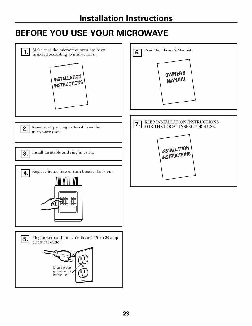
KEEP INSTALLATION INSTRUCTIONSFOR THE LOCAL INSPECTOR’S USE.
Plug power cord into a dedicated 15- to 20-ampelectrical outlet.
7.
Read the Owner’s Manual.6.
Replace house fuse or turn breaker back on. 4.
Remove all packing material from the microwave oven.
2.
Make sure the microwave oven has beeninstalled according to instructions.1.
23
BEFORE YOU USE YOUR MICROWAVE
Ensure properground existsbefore use
Installation Instructions
Install turntable and ring in cavity.3.
5.

DE68-03410A49-40558
04-07 JR Printed in Malaysia
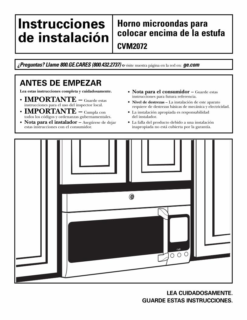
LEA CUIDADOSAMENTE.
GUARDE ESTAS INSTRUCCIONES.
Instruccionesde instalación
Lea estas instrucciones completa y cuidadosamente.
• IMPORTANTE – Guarde estasinstrucciones para el uso del inspector local.
• IMPORTANTE – Cumpla contodos los códigos y ordenanzas gubernamentales.
• Nota para el instalador – Asegúrese de dejarestas instrucciones con el consumidor.
ANTES DE EMPEZAR• Nota para el consumidor – Guarde estas
instrucciones para futura referencia.• Nivel de destrezas – La instalación de este aparato
requiere de destrezas básicas de mecánica y electricidad.• La instalación apropiada es responsabilidad
del instalador.• La falla del producto debido a una instalación
inapropiada no está cubierta por la garantía.
Horno microondas paracolocar encima de la estufa
¿Preguntas? Llame 800.GE.CARES (800.432.2737) o visite nuestra página en la red en: ge.com
CVM2072
2
Recirculación ........................................ 19–22
Cómo adherir el plato de montaje a la pared ............................................19
Cómo preparar el gabinete superior ....19
Inspeccione la ensambladura del microondas ......................................20
Cómo adaptar el calefactor del microondas para la recirculación....20, 21
Cómo montar el hornomicroondas ......................................21, 22
Cómo instalar el filtro de carbonilla....22
Antes de comenzar a usar su horno microondas.... 23
CONTENIDO
Información general
Instrucciones de seguridad importantes .................. 3
Requisitos eléctricos ................................................ 3
Campana de escape.............................................. 4, 5
Daños – Envío / Instalación .................................... 6
Partes incluidas........................................................ 6
Herramientas que necesitará.................................... 7
Espacio de montaje .................................................. 7
Guía de instalación paso por paso
Cómo colocar el plato de montaje ......................8–10
Cómo remover el plato de montaje................8
Cómo encontrar los postes de viga en la pared........................................ 8
Cómo determinar la localización de las placas de la pared ........................................ 9
Cómo alinear la placa de la pared .............. 10
Tipos de instalación.......................................... 11–22
Escape superior exterior ........................ 12–14
Cómo adherir la placa de montaje a la pared ............................................12
Preparación del gabinete superior ......13
Cómo inspeccionar si la operación del regulador de tiro es apropiada ......13
Cómo montar el horno microondas ....................................13, 14
Cómo ajustar el adaptador de escape ..14
Cómo conectar la red de conductos ....14
Escape posterior externo ...................... 15–18
Cómo preparar la pared posterior para el escape posterior exterior ........15
Cómo remover el adaptador de escape ..15
Cómo adherir el plato de montaje a la pared ............................................16
Cómo preparar el gabinete superior....16
Cómo adaptar el calefactor del microondas para el escape exterior posterior ............................16, 17
Cómo montar el horno microondas ....18
A
B
C
Instrucciones de instalación
3
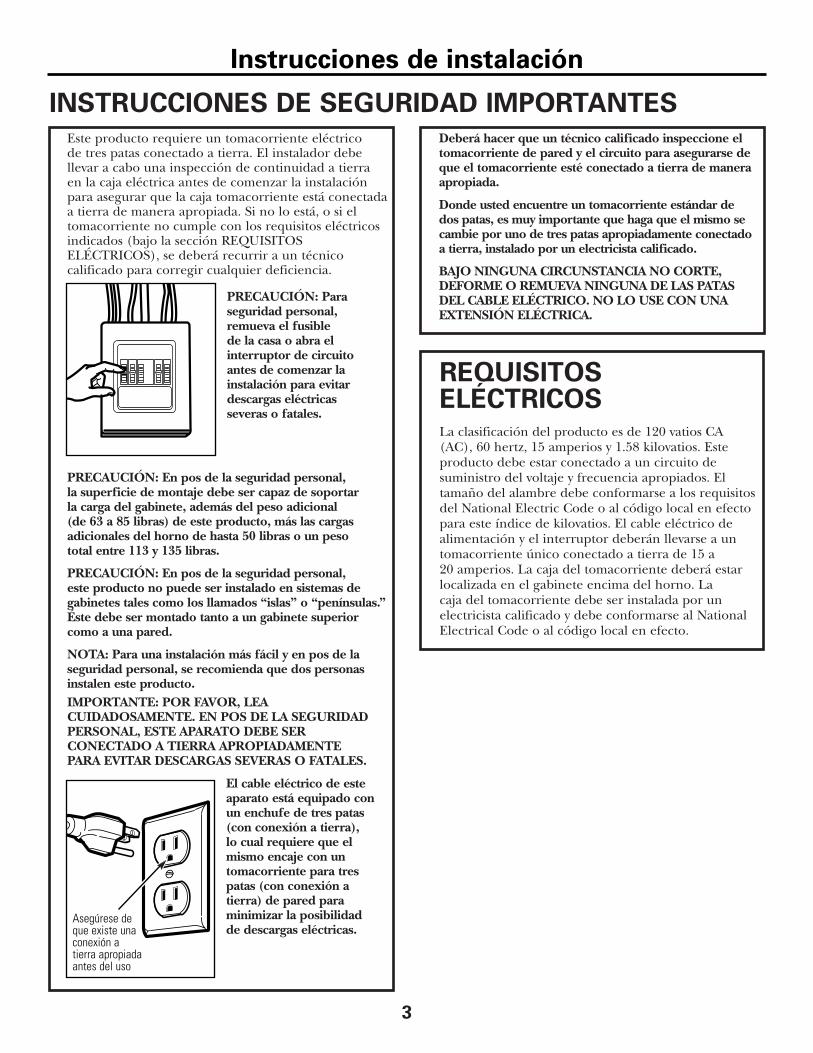
INSTRUCCIONES DE SEGURIDAD IMPORTANTESEste producto requiere un tomacorriente eléctrico de tres patas conectado a tierra. El instalador debe llevar a cabo una inspección de continuidad a tierra en la caja eléctrica antes de comenzar la instalación para asegurar que la caja tomacorriente está conectada a tierra de manera apropiada. Si no lo está, o si eltomacorriente no cumple con los requisitos eléctricosindicados (bajo la sección REQUISITOS ELÉCTRICOS), se deberá recurrir a un técnico calificado para corregir cualquier deficiencia.
PRECAUCIÓN: Paraseguridad personal, remueva el fusible de la casa o abra el interruptor de circuito antes de comenzar lainstalación para evitardescargas eléctricas severas o fatales.
PRECAUCIÓN: En pos de la seguridad personal, la superficie de montaje debe ser capaz de soportar la carga del gabinete, además del peso adicional (de 63 a 85 libras) de este producto, más las cargasadicionales del horno de hasta 50 libras o un peso total entre 113 y 135 libras.
PRECAUCIÓN: En pos de la seguridad personal, este producto no puede ser instalado en sistemas degabinetes tales como los llamados “islas” o “penínsulas.”Éste debe ser montado tanto a un gabinete superior como a una pared.
NOTA: Para una instalación más fácil y en pos de laseguridad personal, se recomienda que dos personasinstalen este producto.IMPORTANTE: POR FAVOR, LEA CUIDADOSAMENTE. EN POS DE LA SEGURIDADPERSONAL, ESTE APARATO DEBE SER CONECTADO A TIERRA APROPIADAMENTE PARA EVITAR DESCARGAS SEVERAS O FATALES.
El cable eléctrico de esteaparato está equipado con un enchufe de tres patas (con conexión a tierra), lo cual requiere que el mismo encaje con untomacorriente para tres patas (con conexión a tierra) de pared paraminimizar la posibilidad de descargas eléctricas.
Deberá hacer que un técnico calificado inspeccione eltomacorriente de pared y el circuito para asegurarse deque el tomacorriente esté conectado a tierra de maneraapropiada.
Donde usted encuentre un tomacorriente estándar dedos patas, es muy importante que haga que el mismo secambie por uno de tres patas apropiadamente conectadoa tierra, instalado por un electricista calificado.
BAJO NINGUNA CIRCUNSTANCIA NO CORTE,DEFORME O REMUEVA NINGUNA DE LAS PATASDEL CABLE ELÉCTRICO. NO LO USE CON UNAEXTENSIÓN ELÉCTRICA.
REQUISITOSELÉCTRICOSLa clasificación del producto es de 120 vatios CA(AC), 60 hertz, 15 amperios y 1.58 kilovatios. Esteproducto debe estar conectado a un circuito desuministro del voltaje y frecuencia apropiados. Eltamaño del alambre debe conformarse a los requisitosdel National Electric Code o al código local en efectopara este índice de kilovatios. El cable eléctrico dealimentación y el interruptor deberán llevarse a untomacorriente único conectado a tierra de 15 a 20 amperios. La caja del tomacorriente deberá estarlocalizada en el gabinete encima del horno. La caja del tomacorriente debe ser instalada por unelectricista calificado y debe conformarse al NationalElectrical Code o al código local en efecto.
Asegúrese deque existe unaconexión atierra apropiadaantes del uso
Instrucciones de instalación
4
LONGITUD NÚMERO LONGITUD
PARTES DEL CONDUCTO EQUIVALENTE x USADO = EQUIVALENTE
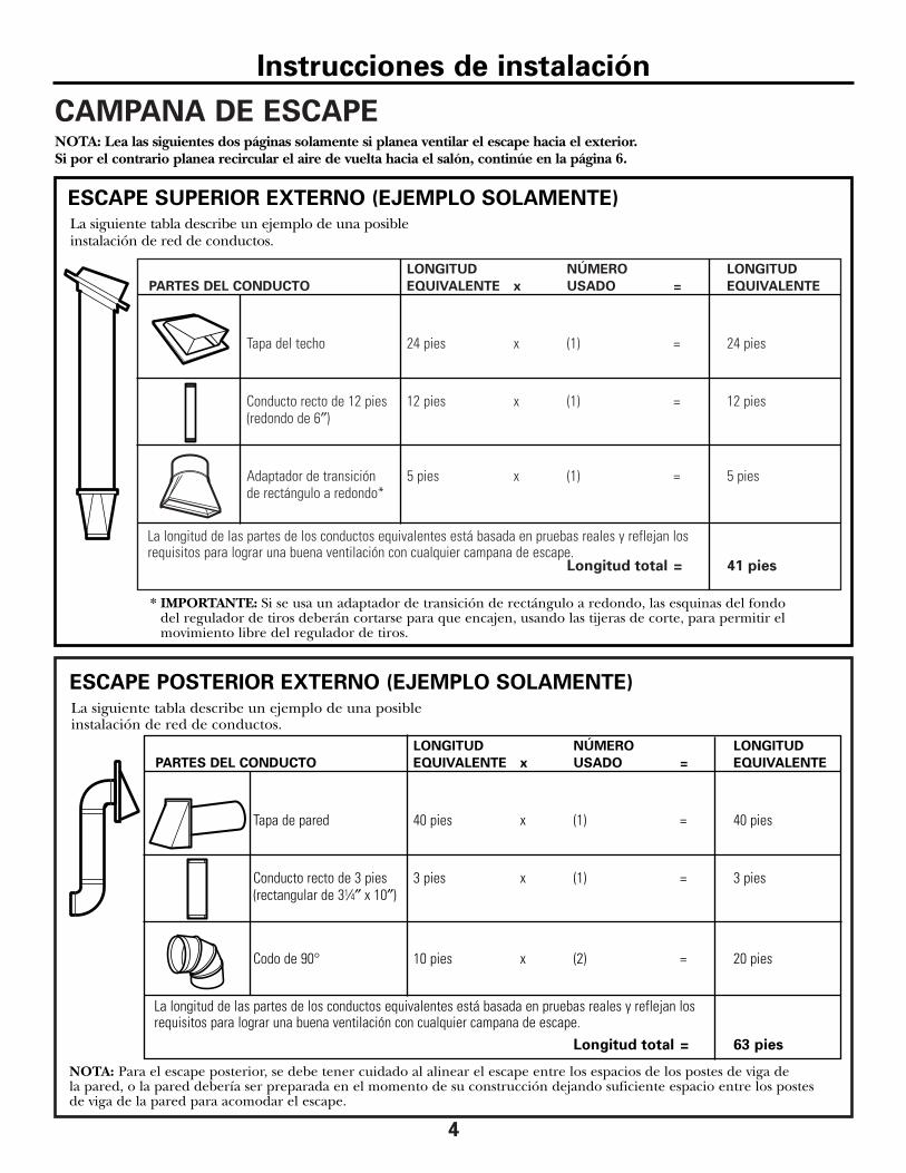
Tapa del techo 24 pies x (1) = 24 pies
Conducto recto de 12 pies 12 pies x (1) = 12 pies(redondo de 6″)
Adaptador de transición 5 pies x (1) = 5 piesde rectángulo a redondo*
La longitud de las partes de los conductos equivalentes está basada en pruebas reales y reflejan los requisitos para lograr una buena ventilación con cualquier campana de escape.
Longitud total = 41 pies
CAMPANA DE ESCAPE
La siguiente tabla describe un ejemplo de una posibleinstalación de red de conductos.
NOTA: Lea las siguientes dos páginas solamente si planea ventilar el escape hacia el exterior. Si por el contrario planea recircular el aire de vuelta hacia el salón, continúe en la página 6.
ESCAPE SUPERIOR EXTERNO (EJEMPLO SOLAMENTE)
NOTA: Para el escape posterior, se debe tener cuidado al alinear el escape entre los espacios de los postes de viga de la pared, o la pared debería ser preparada en el momento de su construcción dejando suficiente espacio entre los postes de viga de la pared para acomodar el escape.
* IMPORTANTE: Si se usa un adaptador de transición de rectángulo a redondo, las esquinas del fondodel regulador de tiros deberán cortarse para que encajen, usando las tijeras de corte, para permitir elmovimiento libre del regulador de tiros.
La siguiente tabla describe un ejemplo de una posibleinstalación de red de conductos.
Instrucciones de instalación
ESCAPE POSTERIOR EXTERNO (EJEMPLO SOLAMENTE)
LONGITUD NÚMERO LONGITUD
PARTES DEL CONDUCTO EQUIVALENTE x USADO = EQUIVALENTE
Tapa de pared 40 pies x (1) = 40 pies
Conducto recto de 3 pies 3 pies x (1) = 3 pies(rectangular de 31⁄4″ x 10″)
Codo de 90° 10 pies x (2) = 20 pies
La longitud de las partes de los conductos equivalentes está basada en pruebas reales y reflejan los requisitos para lograr una buena ventilación con cualquier campana de escape.
Longitud total = 63 pies
5
La longitud de las partes de conductos equivalentes está basada en pruebas reales y reflejan los requisitos para lograr una buenaventilación con cualquier campana de escape.
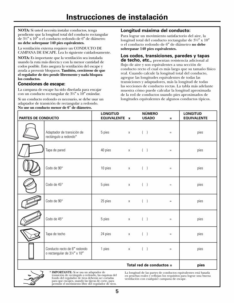
* IMPORTANTE: Si se usa un adaptador detransición de rectángulo a redondo, las esquinas delfondo del regulador de tiros deberán ser cortadaspara que encajen, usando las tijeras de corte, parapermitir el movimiento libre del regulador de tiros.
NOTA: Si usted necesita instalar conductos, tengapendiente que la longitud total del conducto rectangular de 31⁄4″ x 10″ o el conducto redondo de 6″ de diámetro no debe sobrepasar 140 pies equivalentes. La ventilación externa requiere un CONDUCTO DECAMPANA DE ESCAPE. Lea lo siguiente cuidadosamente. NOTA: Es importante que la ventilación sea instaladausando la ruta más directa y con la menor cantidad decodos posible. Esto asegura la ventilación del escape y ayuda a prevenir bloqueos. También, cerciórese de que el regulador de tiro pende libremente y nada bloquea los conductos.Conexiones de escape:
La campana de escape ha sido diseñada para encajar con un conducto rectangular de 31⁄4″ x 10″ estándar.Si un conducto redondo es necesario, se debe usar unadaptador de transición de rectangular a redondo. No use un conducto menor de 6″ de diámetro.
Longitud máxima del conducto:Para lograr un movimiento satisfactorio del aire, lalongitud total del conducto rectangular de 31⁄4″ x 10″o el conducto redondo de 6″ de diámetro no debesobrepasar 140 pies equivalentes.
Los codos, transiciones, paredes y tapas de techo, etc., presentan resistencia adicional alflujo de aire y son equivalentes a una sección deconducto recto el cual es más largo que su tamaño físicoreal. Cuando calcule la longitud total del conducto,agregue las longitudes equivalentes de todas lastransiciones y adaptadores, más la longitud de todas las secciones de conducto rectas. La tabla más adelantemuestra cómo puede calcular la longitud aproximada de la red de conductos usando pies aproximados delongitudes equivalentes de algunos conductos típicos.
Instrucciones de instalación
LONGITUD NÚMERO LONGITUD
PARTES DE CONDUCTO EQUIVALENTE x USADO = EQUIVALENTE
Adaptador de transición de 5 pies x ( ) = piesrectángulo a redondo*
Tapa de pared 40 pies x ( ) = pies
Codo de 90° 10 pies x ( ) = pies
Codo de 45° 5 pies x ( ) = pies
Codo de 90° 25 pies x ( ) = pies
Codo de 45° 5 pies x ( ) = pies
Tapa de techo 24 pies x ( ) = pies
Conducto recto de 6″ redondo 1 pies x ( ) = pieso rectangular de 31⁄4″ x 10″
Total red de conductos = pies

6
• Si la unidad se daña durante el envío, devuelva la unidad al almacén donde la adquirió para su reparación o reemplazo.
• Si el cliente daña la unidad, la reparación o elreemplazo es responsabilidad del cliente.
• Si el instalador daña la unidad (si no es el cliente),la reparación o reemplazo se debe hacer pormedio de un arreglo entre el cliente y el instalador.
DAÑOS – ENVÍO /INSTALACIÓN
Instrucciones de instalación
PARTE CANTIDAD
Tornillos de madera 2(1⁄4″ x 2″)
Tornillos basculantes 4(y tuercas de mariposa)(1⁄4″ x 3″)
Tornillos de máquina 3autoalineables (1⁄4″-28 x 31⁄4″)
Arandela aislante de 2nilón (para gabinetes metálicos)
PARTES INCLUIDAS
Usted encontrará los elementos de instalación en un paquete junto con la unidad. Inspeccione paracerciorarse de que tiene todas las partes.NOTA: Se incluyen algunas partes adicionales.
PAQUETE DE ELEMENTOS
PARTES ADICIONALES
PARTE CANTIDAD
Plantilla para 1el gabinete superior
Plantilla para 1la pared posterior
Instrucciones 1de instalación
Filtros de 2grasa empacados por separado
7
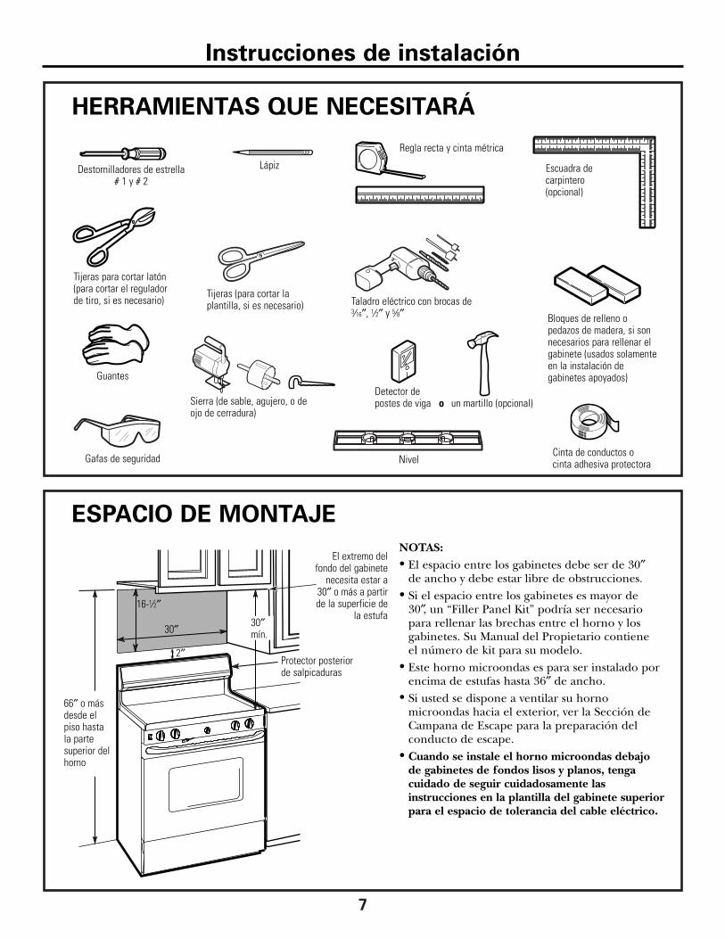
HERRAMIENTAS QUE NECESITARÁ
Destornilladores de estrella# 1 y # 2
Lápiz
Regla recta y cinta métrica
Escuadra decarpintero (opcional)
Tijeras para cortar latón(para cortar el regulador de tiro, si es necesario) Taladro eléctrico con brocas de
3⁄16″, 1⁄2″ y 5⁄8″
un martillo (opcional)Detector depostes de viga o
Bloques de relleno opedazos de madera, si sonnecesarios para rellenar elgabinete (usados solamenteen la instalación degabinetes apoyados)Guantes
Sierra (de sable, agujero, o de ojo de cerradura)
NivelCinta de conductos ocinta adhesiva protectora
ESPACIO DE MONTAJE
NOTAS:• El espacio entre los gabinetes debe ser de 30″
de ancho y debe estar libre de obstrucciones.• Si el espacio entre los gabinetes es mayor de
30″, un “Filler Panel Kit” podría ser necesariopara rellenar las brechas entre el horno y losgabinetes. Su Manual del Propietario contiene el número de kit para su modelo.
• Este horno microondas es para ser instalado porencima de estufas hasta 36″ de ancho.
• Si usted se dispone a ventilar su hornomicroondas hacia el exterior, ver la Sección deCampana de Escape para la preparación delconducto de escape.
• Cuando se instale el horno microondas debajode gabinetes de fondos lisos y planos, tengacuidado de seguir cuidadosamente lasinstrucciones en la plantilla del gabinete superiorpara el espacio de tolerancia del cable eléctrico.
Protector posteriorde salpicaduras
66″ o másdesde elpiso hastala partesuperior delhorno
30″
2″
30″mín.
16-1⁄2″
El extremo delfondo del gabinete
necesita estar a30″ o más a partirde la superficie de
la estufa
Instrucciones de instalación
Tijeras (para cortar laplantilla, si es necesario)
Gafas de seguridad
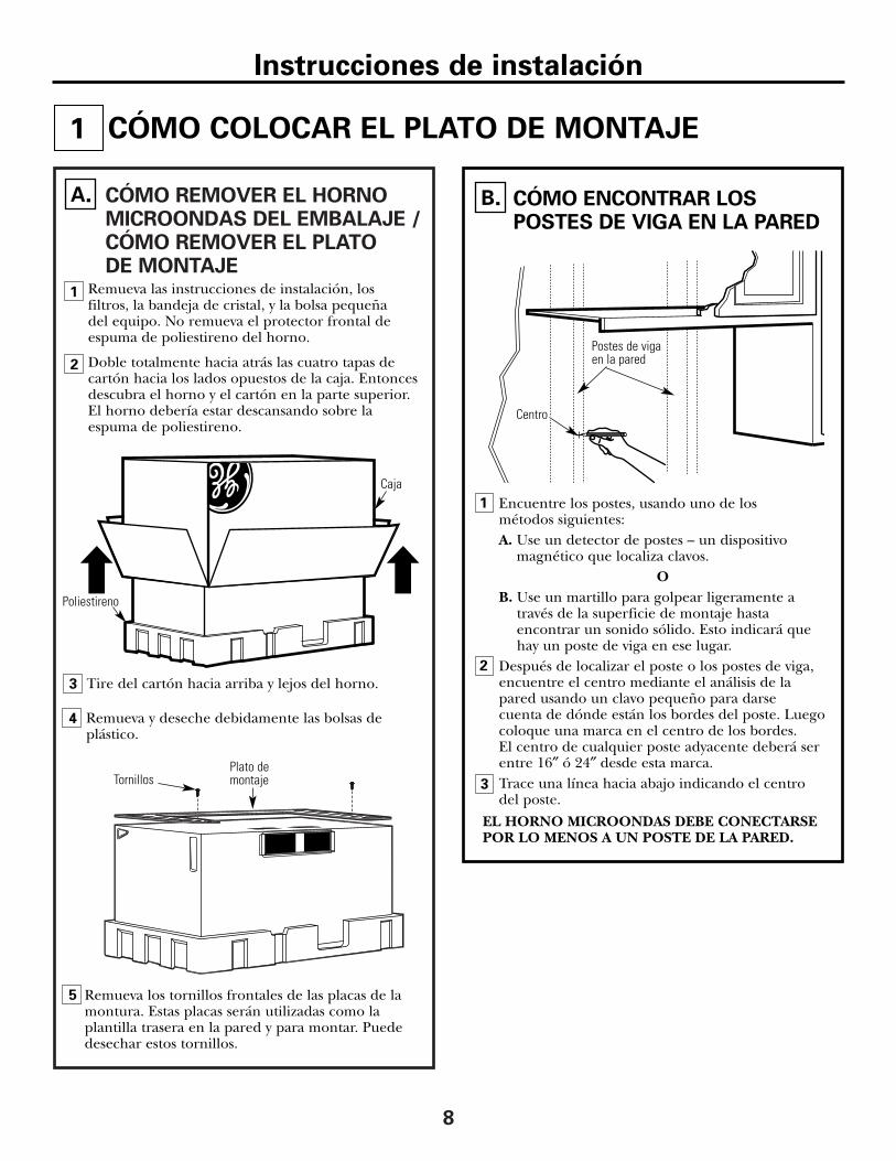
CÓMO REMOVER EL HORNOMICROONDAS DEL EMBALAJE /CÓMO REMOVER EL PLATO DE MONTAJE
8
Remueva las instrucciones de instalación, losfiltros, la bandeja de cristal, y la bolsa pequeña del equipo. No remueva el protector frontal deespuma de poliestireno del horno.
Doble totalmente hacia atrás las cuatro tapas decartón hacia los lados opuestos de la caja. Entoncesdescubra el horno y el cartón en la parte superior.El horno debería estar descansando sobre laespuma de poliestireno.
A.
Caja
Tire del cartón hacia arriba y lejos del horno.
Remueva los tornillos frontales de las placas de lamontura. Estas placas serán utilizadas como laplantilla trasera en la pared y para montar. Puededesechar estos tornillos.
Plato demontajeTornillos
2
Poliestireno
3
5
Remueva y deseche debidamente las bolsas deplástico.
4
1
Encuentre los postes, usando uno de los métodos siguientes:A. Use un detector de postes – un dispositivo
magnético que localiza clavos.O
B. Use un martillo para golpear ligeramente a través de la superficie de montaje hasta encontrar un sonido sólido. Esto indicará que hay un poste de viga en ese lugar.
Después de localizar el poste o los postes de viga,encuentre el centro mediante el análisis de la pared usando un clavo pequeño para darse cuenta de dónde están los bordes del poste. Luegocoloque una marca en el centro de los bordes. El centro de cualquier poste adyacente deberá serentre 16″ ó 24″ desde esta marca.Trace una línea hacia abajo indicando el centro del poste.
EL HORNO MICROONDAS DEBE CONECTARSEPOR LO MENOS A UN POSTE DE LA PARED.
1
CÓMO ENCONTRAR LOSPOSTES DE VIGA EN LA PARED
B.
2
CÓMO COLOCAR EL PLATO DE MONTAJE1
Postes de vigaen la pared
Centro
3
Instrucciones de instalación
9
CÓMO DETERMINAR LA LOCALIZACIÓN DEL PLATO DE MONTAJEDEBAJO DE SU GABINETE
C.
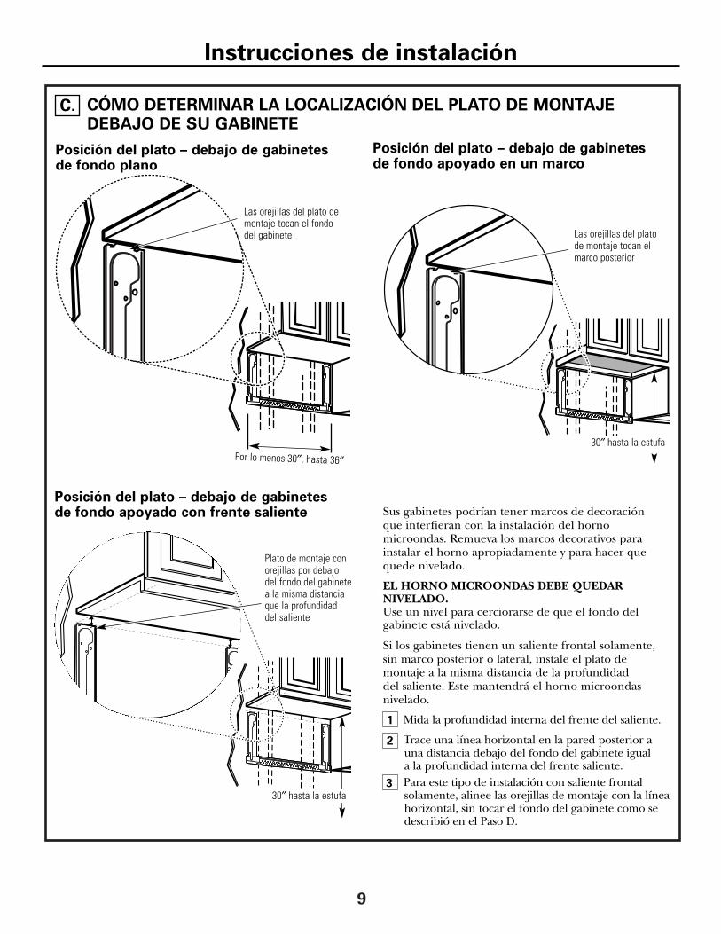
Sus gabinetes podrían tener marcos de decoración que interfieran con la instalación del hornomicroondas. Remueva los marcos decorativos parainstalar el horno apropiadamente y para hacer quequede nivelado.
EL HORNO MICROONDAS DEBE QUEDARNIVELADO.Use un nivel para cerciorarse de que el fondo delgabinete está nivelado.
Si los gabinetes tienen un saliente frontal solamente,sin marco posterior o lateral, instale el plato demontaje a la misma distancia de la profundidad del saliente. Este mantendrá el horno microondasnivelado.
Mida la profundidad interna del frente del saliente.
Trace una línea horizontal en la pared posterior auna distancia debajo del fondo del gabinete igual a la profundidad interna del frente saliente.Para este tipo de instalación con saliente frontalsolamente, alinee las orejillas de montaje con la líneahorizontal, sin tocar el fondo del gabinete como sedescribió en el Paso D.
Posición del plato – debajo de gabinetes de fondo plano
Posición del plato – debajo de gabinetes de fondo apoyado con frente saliente
Las orejillas del plato demontaje tocan el fondo del gabinete
Plato de montaje conorejillas por debajodel fondo del gabinetea la misma distanciaque la profundidad del saliente
Por lo menos 30″, hasta 36″
Posición del plato – debajo de gabinetes de fondo apoyado en un marco
Las orejillas del platode montaje tocan elmarco posterior
Instrucciones de instalación
30″ hasta la estufa
30″ hasta la estufa
1
2
3

10
CÓMO ALINEAR EL PLATO DE MONTAJE SOBRE LA PARED
Trace una línea vertical en la pared en el centro delespacio de 30″ de ancho.Use el plato de montaje como la plantilla para la paredposterior. Coloque el plato de montaje en la pared,cerciorándose de que las orejillas se encuentrantocando el fondo del gabinete o la línea horizontaltrazada en el Paso C para gabinetes con salientefrontal. Alinee la muesca y línea del centro en el fondodel plato de montaje con la línea de centro en la pared.Mientras sostiene el plato de montaje con una mano,trace círculos en la pared en los agujeros A, B, C y D(ver la ilustración anterior / la placa real está marcadacon flechas). Deben usarse cuatro agujeros para el montaje.
NOTA: Los agujeros C y D van en el interior del áreaE. Si ni el C ni el D están en un poste de viga,encuentre un poste en algún otro lugar en el área E ymarque un quinto círculo para alinearse con el poste.Es importante usar por lo menos un tornillo de maderamontado firmemente en un poste para apoyar el pesodel horno.Aparte el plato de montaje.Perfore agujeros en los círculos. Si hay un poste de viga, perfore un agujero de 3/16″ para los tornillos demadera. Para los agujeros que no quedaron alineadoscon el poste de viga, perfore un agujero de 5/8″ paralos tornillos basculantes. NOTA: TODAVÍA NO MONTE EL PLATO.
2
34
Trace una líneavertical en la pared a partir del centro del gabinete superior
Area E
Agujero A
Agujero B
Agujero D
D.
Instrucciones de instalación
PRECAUCIÓN: Useguantes de protección para evitar cortaduras en sus dedos con losextremos filosos.
1
Muescasde la líneadel centro
Agujero C
11
A
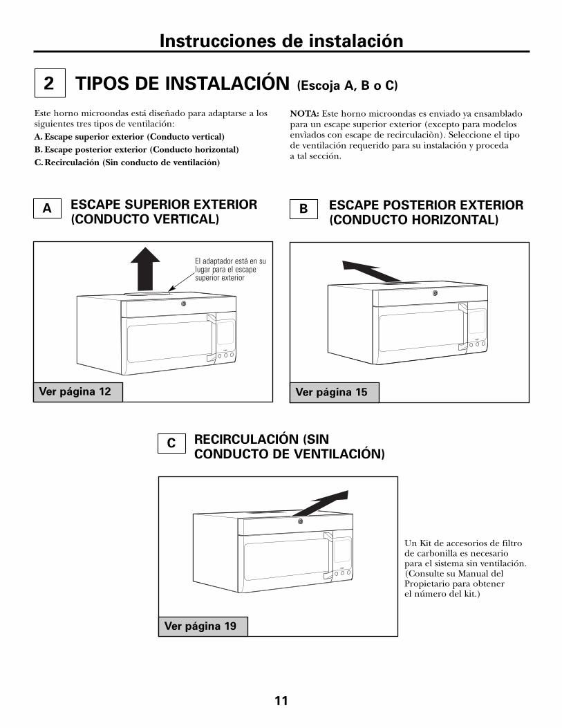
TIPOS DE INSTALACIÓN (Escoja A, B o C)
Este horno microondas está diseñado para adaptarse a lossiguientes tres tipos de ventilación: A. Escape superior exterior (Conducto vertical)B. Escape posterior exterior (Conducto horizontal)C.Recirculación (Sin conducto de ventilación)
NOTA: Este horno microondas es enviado ya ensambladopara un escape superior exterior (excepto para modelosenvìados con escape de recirculaciòn). Seleccione el tipode ventilación requerido para su instalación y proceda a tal sección.
ESCAPE SUPERIOR EXTERIOR(CONDUCTO VERTICAL)
ESCAPE POSTERIOR EXTERIOR(CONDUCTO HORIZONTAL)
RECIRCULACIÓN (SINCONDUCTO DE VENTILACIÓN)
Ver página 12 Ver página 15
Ver página 19
Un Kit de accesorios de filtrode carbonilla es necesariopara el sistema sin ventilación.(Consulte su Manual delPropietario para obtener el número del kit.)
El adaptador está en sulugar para el escapesuperior exterior
Instrucciones de instalación
2
B
C
12
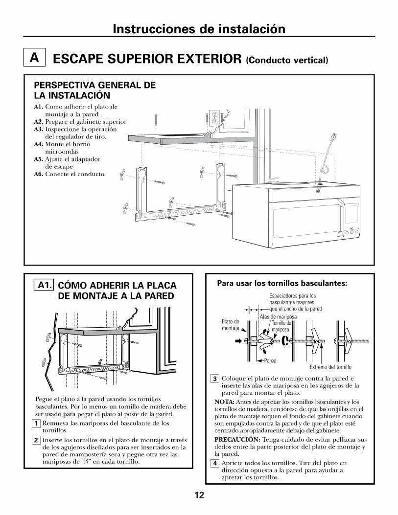
Coloque el plato de montaje contra la pared einserte las alas de mariposa en los agujeros de lapared para montar el plato.
NOTA: Antes de apretar los tornillos basculantes y lostornillos de madera, cerciórese de que las orejillas en elplato de montaje toquen el fondo del gabinete cuandoson empujadas contra la pared y de que el plato estécentrado apropiadamente debajo del gabinete.PRECAUCIÓN: Tenga cuidado de evitar pellizcar susdedos entre la parte posterior del plato de montaje yla pared.
Apriete todos los tornillos. Tire del plato endirección opuesta a la pared para ayudar a apretar los tornillos.
3
A
4
CÓMO ADHERIR LA PLACA DE MONTAJE A LA PARED
A1.
ESCAPE SUPERIOR EXTERIOR (Conducto vertical)
Pegue el plato a la pared usando los tornillosbasculantes. Por lo menos un tornillo de madera debeser usado para pegar el plato al poste de la pared.
Remueva las mariposas del basculante de lostornillos.
Inserte los tornillos en el plato de montaje a travésde los agujeros diseñados para ser insertados en lapared de mampostería seca y pegue otra vez lasmariposas de 3⁄4″ en cada tornillo.
1
PERSPECTIVA GENERAL DELA INSTALACIÓNA1. Como adherir el plato de
montaje a la paredA2. Prepare el gabinete superiorA3. Inspeccione la operación
del regulador de tiro.A4. Monte el horno
microondasA5. Ajuste el adaptador
de escapeA6. Conecte el conducto
Pared
Plato demontaje
Espaciadores para losbasculantes mayores que el ancho de la pared
Extremo del tornillo
Tornillo demariposa
Alas de mariposa
Para usar los tornillos basculantes:
Instrucciones de instalación
2
13
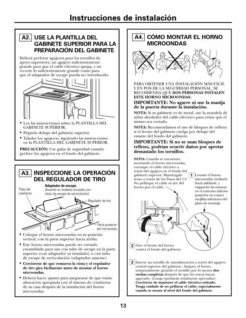
INSPECCIONE LA OPERACIÓNDEL REGULADOR DE TIRO
A3.
Adaptador de escape(Ausente en modelos enviados contubos de escape de recirculación)
Plato delcalefactor
Regulador de tiro
Parte posteriordel microondas
• Coloque el horno microondas en su posiciónvertical, con la parte superior hacia arriba.
• Este horno microondas puede ser enviadoensamblado para uso con tubo de escape en la partesuperior (con adaptador ya instalado) o con tubo de escape de recirculación (adaptador ausente)
• Cerciórese de que remueva la cinta y el regulador de tiro gira fácilmente antes de montar el hornomicroondas.
• Deberá hacer ajustes para asegurarse de que existealineación apropiada con el sistema de conductos de su casa después de la instalación del hornomicroondas.
3
2 Gire el frente del hornocontra el fondo del gabinete.
1
CÓMO MONTAR EL HORNOMICROONDAS
A4.USE LA PLANTILLA DELGABINETE SUPERIOR PARA LAPREPARACIÓN DEL GABINETE
Deberá perforar agujeros para los tornillos de apoyo superiores, un agujero suficientemente grande para que el cable eléctrico quepa, y un recorte lo suficientemente grande como para que el adaptador de escape pueda ser introducido.
A2.
PARA OBTENER UNA INSTALACIÓN MÁS FÁCILY EN POS DE LA SEGURIDAD PERSONAL, SERECOMIENDA QUE DOS PERSONAS INSTALENESTE HORNO MICROONDAS.IMPORTANTE: No agarre ni use la manijade la puerta durante la instalación.NOTA: Si su gabinete es de metal, use la arandela denilón alrededor del cable eléctrico para evitar que elmismo sea cortado.NOTA: Recomendamos el uso de bloques de rellenosi el frente del gabinete cuelga por debajo delestante del fondo del gabinete.
IMPORTANTE: Si no se usan bloques derelleno, podrían ocurrir daños por apretardemasiado los tornillos.
Inserte un tornillo de autoalineación a través del agujerocentral superior del gabinete. Asegure el hornotemporalmente girando el tornillo por lo menos dosvueltas completas después de que las roscas hayanagarrado. (Luego quedarán totalmente apretadas).Cerciórese de mantener el cable eléctrico estirado. Tenga cuidado de no pellizcar el cable, especialmentecuando se monte al nivel del fondo del gabinete.
NOTA: Cuando se encuentremontando el horno microondas,enrosque el cable eléctrico através del agujero en el fondo delgabinete superior. Manténgalotenso a través de los Pasos del 1-3.No pellizque el cable ni tire delhorno por el cable.
Levante el hornomicroondas, inclínelohacia adelante, yenganche las ranurasen el extremo inferiorposterior en cuatroorejillas inferiores delplato de montaje.
• Lea las instrucciones sobre la PLANTILLA DELGABINETE SUPERIOR.
• Péguelo debajo del gabinete superior.• Taladre los agujeros, siguiendo las instrucciones
en la PLANTILLA DEL GABINETE SUPERIOR.
PRECAUCIÓN: Use gafas de seguridad cuandoperfore los agujeros en el fondo del gabinete.
Instrucciones de instalación

4 Pegue el horno microondas a la parte superior delgabinete.
8
7
6
Frente del gabinete
Estante del fondo del gabinete
Apriete los dos tornillos exteriores hacia la parte de arriba del horno microondas. (Mientras aprieta lostornillos, mantenga el horno microondas en su lugarcontra la pared y el gabinete superior.)
Bloque de relleno
Parte superior del horno microondas
Equivalente ala profundidaddel retrocesodel gabinete
Inserte 2 tornillos autoalineables a través de los agujeros exterioressuperiores del horno. Gire dos vueltas completas en cada tornillo.
Apriete el tornillo delcentro completamente.
Instale los filtros de grasa. Ver el Manual delPropietario que viene con el horno microondas.
Tornillo autoalineable
5
CÓMO MONTAR EL HORNOMICROONDAS (continuación)
A4.
14
Parte posteriordel microondas
Para ajustes de frente aparte posterior o de lado alado, deslice el adaptadordel tubo de escape segúnsea necesario.
Plato del calefactor Regulador de tiro
Instrucciones de instalación
CÓMO AJUSTAR ELADAPTADOR DE ESCAPE
A5.
Abra el gabinete superior y ajuste el adaptador deescape para conectarlo al conducto de la casa.
CÓMO CONECTAR EL CONDUCTO
1
2
Extienda el conducto de la casa hacia abajo paraconectarlo con el adaptador de escape. Selle las juntas del conducto de escape usandocinta adhesiva de conductos.
A6.
Conducto de la casa
2Levante el platodel calefactor ydesembrague eladaptador delmicroondas.
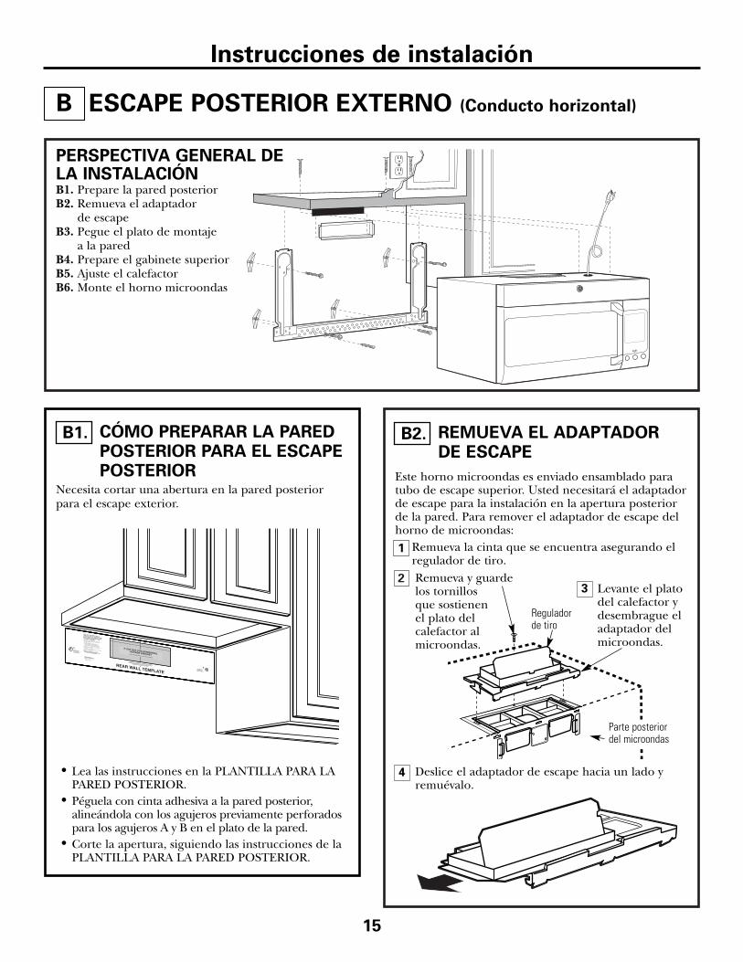
Este horno microondas es enviado ensamblado paratubo de escape superior. Usted necesitará el adaptadorde escape para la instalación en la apertura posteriorde la pared. Para remover el adaptador de escape delhorno de microondas:
Remueva la cinta que se encuentra asegurando elregulador de tiro.
Deslice el adaptador de escape hacia un lado yremuévalo.
Parte posteriordel microondas
15
3
4
Reguladorde tiro
1
ESCAPE POSTERIOR EXTERNO (Conducto horizontal)
PERSPECTIVA GENERAL DELA INSTALACIÓNB1. Prepare la pared posteriorB2. Remueva el adaptador
de escapeB3. Pegue el plato de montaje
a la paredB4. Prepare el gabinete superiorB5. Ajuste el calefactorB6. Monte el horno microondas
Instrucciones de instalación
B
CÓMO PREPARAR LA PAREDPOSTERIOR PARA EL ESCAPEPOSTERIOR
B1.
Necesita cortar una abertura en la pared posteriorpara el escape exterior.
• Lea las instrucciones en la PLANTILLA PARA LAPARED POSTERIOR.
• Péguela con cinta adhesiva a la pared posterior,alineándola con los agujeros previamente perforadospara los agujeros A y B en el plato de la pared.
• Corte la apertura, siguiendo las instrucciones de laPLANTILLA PARA LA PARED POSTERIOR.
REMUEVA EL ADAPTADOR DE ESCAPE
B2.
Remueva y guardelos tornillos que sostienen el plato delcalefactor almicroondas.
16
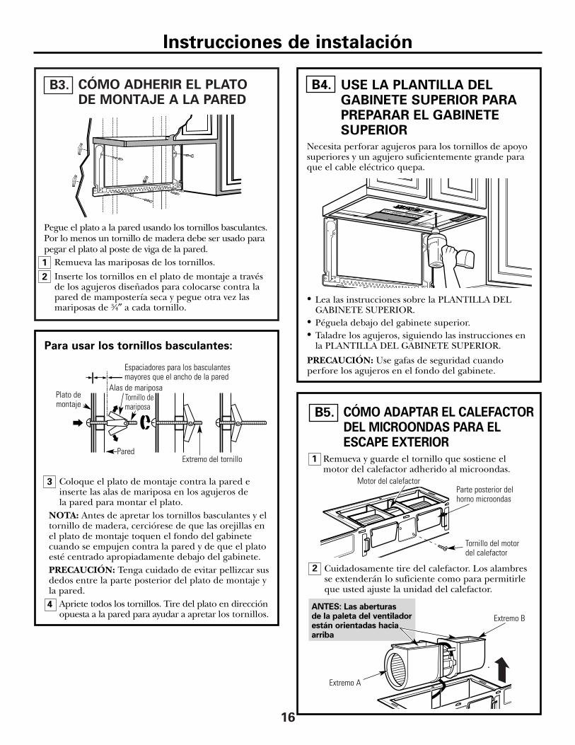
CÓMO ADHERIR EL PLATO DE MONTAJE A LA PARED
B3.
Pegue el plato a la pared usando los tornillos basculantes.Por lo menos un tornillo de madera debe ser usado parapegar el plato al poste de viga de la pared.
Remueva las mariposas de los tornillos.
Inserte los tornillos en el plato de montaje a travésde los agujeros diseñados para colocarse contra lapared de mampostería seca y pegue otra vez lasmariposas de 3⁄4″ a cada tornillo.
1
2
USE LA PLANTILLA DELGABINETE SUPERIOR PARAPREPARAR EL GABINETESUPERIOR
B4.
• Lea las instrucciones sobre la PLANTILLA DELGABINETE SUPERIOR.
• Péguela debajo del gabinete superior.• Taladre los agujeros, siguiendo las instrucciones en
la PLANTILLA DEL GABINETE SUPERIOR.
PRECAUCIÓN: Use gafas de seguridad cuandoperfore los agujeros en el fondo del gabinete.
Pared
Plato demontaje
Espaciadores para los basculantesmayores que el ancho de la pared
Tornillo demariposa
Alas de mariposa
Para usar los tornillos basculantes:
Extremo del tornillo
Instrucciones de instalación
Necesita perforar agujeros para los tornillos de apoyosuperiores y un agujero suficientemente grande paraque el cable eléctrico quepa.
Coloque el plato de montaje contra la pared einserte las alas de mariposa en los agujeros de la pared para montar el plato.
NOTA: Antes de apretar los tornillos basculantes y eltornillo de madera, cerciórese de que las orejillas enel plato de montaje toquen el fondo del gabinetecuando se empujen contra la pared y de que el platoesté centrado apropiadamente debajo del gabinete.PRECAUCIÓN: Tenga cuidado de evitar pellizcar susdedos entre la parte posterior del plato de montaje yla pared.
Apriete todos los tornillos. Tire del plato en direcciónopuesta a la pared para ayudar a apretar los tornillos.
3
4
1 Remueva y guarde el tornillo que sostiene elmotor del calefactor adherido al microondas.
Parte posterior delhorno microondas
Motor del calefactor
Tornillo del motordel calefactor
ANTES: Las aberturas de la paleta del ventiladorestán orientadas haciaarriba
2
CÓMO ADAPTAR EL CALEFACTORDEL MICROONDAS PARA ELESCAPE EXTERIOR
B5.
Extremo B
Extremo A
Cuidadosamente tire del calefactor. Los alambresse extenderán lo suficiente como para permitirleque usted ajuste la unidad del calefactor.
DESPUES: Lasaberturas de lapaleta del ventiladorestán orientadashacia atrás
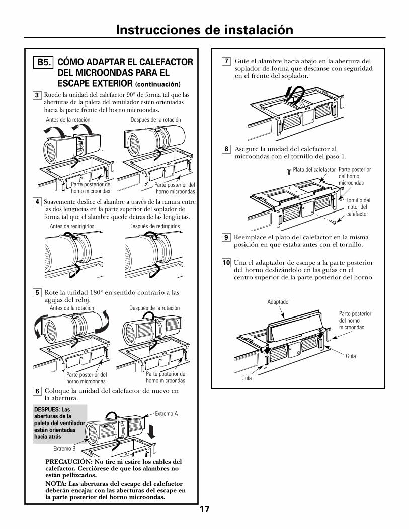
Coloque la unidad del calefactor de nuevo en la abertura.
6
9 Reemplace el plato del calefactor en la mismaposición en que estaba antes con el tornillo.
8
Ruede la unidad del calefactor 90° de forma tal que lasaberturas de la paleta del ventilador estén orientadashacia la parte frente del horno microondas.
17
Plato del calefactor
Tornillo delmotor delcalefactor
Asegure la unidad del calefactor almicroondas con el tornillo del paso 1.
Antes de la rotación Después de la rotación
Parte posteriordel hornomicroondas
Extremo A
Extremo B
Parte posterior delhorno microondas
Parte posterior delhorno microondas
PRECAUCIÓN: No tire ni estire los cables delcalefactor. Cerciórese de que los alambres noestán pellizcados.NOTA: Las aberturas del escape del calefactordeberán encajar con las aberturas del escape en la parte posterior del horno microondas.
5
CÓMO ADAPTAR EL CALEFACTORDEL MICROONDAS PARA ELESCAPE EXTERIOR (continuación)
B5.
Rote la unidad 180° en sentido contrario a lasagujas del reloj.
Antes de la rotación Después de la rotación
Parte posterior delhorno microondas
Parte posterior delhorno microondas
Instrucciones de instalación
10 Una el adaptador de escape a la parte posteriordel horno deslizándolo en las guías en elcentro superior de la parte posterior del horno.
Guía
Guía
Adaptador
Parte posteriordel hornomicroondas
3
4 Suavemente deslice el alambre a través de la ranura entrelas dos lengüetas en la parte superior del soplador deforma tal que el alambre quede detrás de las lengüetas.
Antes de redirigirlos Después de redirigirlos
7 Guíe el alambre hacia abajo en la abertura delsoplador de forma que descanse con seguridaden el frente del soplador.
3
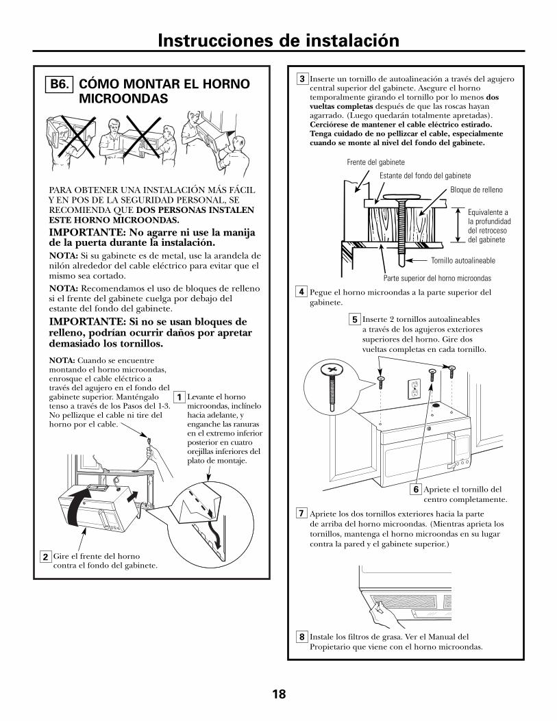
2 Gire el frente del hornocontra el fondo del gabinete.
1
CÓMO MONTAR EL HORNOMICROONDAS
PARA OBTENER UNA INSTALACIÓN MÁS FÁCILY EN POS DE LA SEGURIDAD PERSONAL, SERECOMIENDA QUE DOS PERSONAS INSTALENESTE HORNO MICROONDAS.IMPORTANTE: No agarre ni use la manijade la puerta durante la instalación.NOTA: Si su gabinete es de metal, use la arandela denilón alrededor del cable eléctrico para evitar que elmismo sea cortado.NOTA: Recomendamos el uso de bloques de rellenosi el frente del gabinete cuelga por debajo delestante del fondo del gabinete.
IMPORTANTE: Si no se usan bloques derelleno, podrían ocurrir daños por apretardemasiado los tornillos.
Inserte un tornillo de autoalineación a través del agujerocentral superior del gabinete. Asegure el hornotemporalmente girando el tornillo por lo menos dosvueltas completas después de que las roscas hayanagarrado. (Luego quedarán totalmente apretadas).Cerciórese de mantener el cable eléctrico estirado. Tenga cuidado de no pellizcar el cable, especialmentecuando se monte al nivel del fondo del gabinete.
NOTA: Cuando se encuentremontando el horno microondas,enrosque el cable eléctrico através del agujero en el fondo delgabinete superior. Manténgalotenso a través de los Pasos del 1-3.No pellizque el cable ni tire delhorno por el cable.
Levante el hornomicroondas, inclínelohacia adelante, yenganche las ranurasen el extremo inferiorposterior en cuatroorejillas inferiores delplato de montaje.
18
B6.
4 Pegue el horno microondas a la parte superior delgabinete.
8
7
6
Frente del gabinete
Estante del fondo del gabinete
Apriete los dos tornillos exteriores hacia la parte de arriba del horno microondas. (Mientras aprieta lostornillos, mantenga el horno microondas en su lugarcontra la pared y el gabinete superior.)
Bloque de relleno
Parte superior del horno microondas
Equivalente ala profundidaddel retrocesodel gabinete
Inserte 2 tornillos autoalineables a través de los agujeros exterioressuperiores del horno. Gire dos vueltas completas en cada tornillo.
Apriete el tornillo delcentro completamente.
Instale los filtros de grasa. Ver el Manual delPropietario que viene con el horno microondas.
Tornillo autoalineable
5
Instrucciones de instalación
19
Instrucciones de instalación
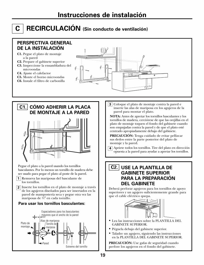
USE LA PLANTILLA DEGABINETE SUPERIORPARA LA PREPARACIÓN DEL GABINETE
C2.
RECIRCULACIÓN (Sin conducto de ventilación)
PERSPECTIVA GENERALDE LA INSTALACIÓNC1. Pegue el plato de montaje
a la paredC2. Prepare el gabinete superiorC3. Inspeccione la ensambladura del
microondasC4. Ajuste el calefactorC5. Monte el horno microondasC6. Instale el filtro de carbonilla
• Lea las instrucciones sobre la PLANTILLA DELGABINETE SUPERIOR.
• Péguela debajo del gabinete superior.• Taladre un agujero, siguiendo las instrucciones
en la PLANTILLA DEL GABINETE SUPERIOR.
PRECAUCIÓN: Use gafas de seguridad cuandoperfore los agujeros en el fondo del gabinete.
Deberá perforar agujeros para los tornillos de apoyosuperiores y un agujero suficientemente grande paraque el cable eléctrico quepa.
C
Coloque el plato de montaje contra la pared einserte las alas de mariposa en los agujeros de lapared para montar el plato.
NOTA: Antes de apretar los tornillos basculantes y lostornillos de madera, cerciórese de que las orejillas en elplato de montaje toquen el fondo del gabinete cuandoson empujadas contra la pared y de que el plato estécentrado apropiadamente debajo del gabinete.PRECAUCIÓN: Tenga cuidado de evitar pellizcar sus dedos entre la parte posterior del plato demontaje y la pared.
Apriete todos los tornillos. Tire del plato en direcciónopuesta a la pared para ayudar a apretar los tornillos.
4
3CÓMO ADHERIR LA PLACA DE MONTAJE A LA PARED
C1.
Pegue el plato a la pared usando los tornillosbasculantes. Por lo menos un tornillo de madera debeser usado para pegar el plato al poste de la pared.
Remueva las mariposas del basculante de los tornillos.
Inserte los tornillos en el plato de montaje a travésde los agujeros diseñados para ser insertados en lapared de mampostería seca y pegue otra vez lasmariposas de 3⁄4″ en cada tornillo.
1
Pared
Plato demontaje
Espaciadores para los basculantesmayores que el ancho de la pared
Extremo del tornillo
Tornillo demariposa
Alas de mariposa
Para usar los tornillos basculantes:
2
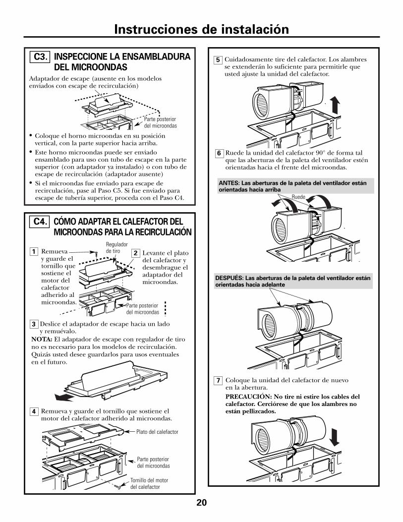
7 Coloque la unidad del calefactor de nuevo en la abertura.PRECAUCIÓN: No tire ni estire los cables delcalefactor. Cerciórese de que los alambres noestán pellizcados.
DESPUÉS: Las aberturas de la paleta del ventilador estánorientadas hacia adelante
5
4
3
6
CÓMO ADAPTAR EL CALEFACTOR DELMICROONDAS PARA LA RECIRCULACIÓN
C4.
20
NOTA: El adaptador de escape con regulador de tirono es necesario para los modelos de recirculación.Quizás usted desee guardarlos para usos eventuales en el futuro.
Cuidadosamente tire del calefactor. Los alambresse extenderán lo suficiente para permitirle queusted ajuste la unidad del calefactor.
Ruede la unidad del calefactor 90° de forma talque las aberturas de la paleta del ventilador esténorientadas hacia el frente del microondas.
Ruede
Deslice el adaptador de escape hacia un lado y remuévalo.
Remueva y guarde el tornillo que sostiene elmotor del calefactor adherido al microondas.
Plato del calefactor
Tornillo del motordel calefactor
Parte posteriordel microondas
Remueva y guarde eltornillo quesostiene elmotor delcalefactoradherido almicroondas.
Levante el platodel calefactor ydesembrague eladaptador delmicroondas.
ANTES: Las aberturas de la paleta del ventilador estánorientadas hacia arriba
Reguladorde tiro
Parte posteriordel microondas
INSPECCIONE LA ENSAMBLADURADEL MICROONDAS
C3.
Adaptador de escape (ausente en los modelosenviados con escape de recirculación)
Parte posteriordel microondas
• Coloque el horno microondas en su posiciónvertical, con la parte superior hacia arriba.
• Este horno microondas puede ser enviadoensamblado para uso con tubo de escape en la partesuperior (con adaptador ya instalado) o con tubo deescape de recirculación (adaptador ausente)
• Si el microondas fue enviado para escape derecirculación, pase al Paso C5. Si fue enviado paraescape de tubería superior, proceda con el Paso C4.
1 2
Instrucciones de instalación
10
9
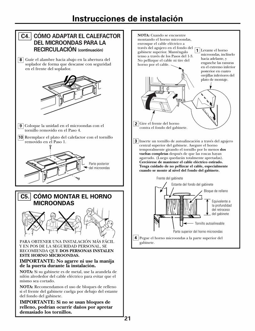
CÓMO ADAPTAR EL CALEFACTOR DEL MICROONDAS PARA LARECIRCULACIÓN (continuación)
C4.
21
Reemplace el plato del calefactor con el tornilloremovido en el Paso 1.
Coloque la unidad en el microondas con eltornillo removido en el Paso 4.
Parte posteriordel microondas
CÓMO MONTAR EL HORNOMICROONDAS
C5.
PARA OBTENER UNA INSTALACIÓN MÁS FÁCIL Y EN POS DE LA SEGURIDAD PERSONAL, SERECOMIENDA QUE DOS PERSONAS INSTALENESTE HORNO MICROONDAS.IMPORTANTE: No agarre ni use la manijade la puerta durante la instalación.NOTA: Si su gabinete es de metal, use la arandela denilón alrededor del cable eléctrico para evitar que elmismo sea cortado.NOTA: Recomendamos el uso de bloques de relleno si el frente del gabinete cuelga por debajo del estantedel fondo del gabinete.
IMPORTANTE: Si no se usan bloques derelleno, podrían ocurrir daños por apretardemasiado los tornillos.
3
2 Gire el frente del hornocontra el fondo del gabinete.
1
Inserte un tornillo de autoalineación a través del agujerocentral superior del gabinete. Asegure el hornotemporalmente girando el tornillo por lo menos dosvueltas completas después de que las roscas hayanagarrado. (Luego quedarán totalmente apretadas).Cerciórese de mantener el cable eléctrico estirado. Tenga cuidado de no pellizcar el cable, especialmentecuando se monte al nivel del fondo del gabinete.
NOTA: Cuando se encuentremontando el horno microondas,enrosque el cable eléctrico através del agujero en el fondo delgabinete superior. Manténgalotenso a través de los Pasos del 1-3.No pellizque el cable ni tire delhorno por el cable.
Levante el hornomicroondas, inclínelohacia adelante, yenganche las ranurasen el extremo inferiorposterior en cuatroorejillas inferiores delplato de montaje.
4 Pegue el horno microondas a la parte superior delgabinete.
Frente del gabinete
Estante del fondo del gabinete
Bloque de relleno
Parte superior del horno microondas
Equivalente ala profundidaddel retrocesodel gabinete
Tornillo autoalineable
Instrucciones de instalación
Guíe el alambre hacia abajo en la abertura delsoplador de forma que descanse con seguridad en el frente del soplador.
8

6
3
4
2
1
CÓMO INSTALAR EL FILTRODE CARBONILLA
C6.CÓMO MONTAR EL HORNOMICROONDAS (continuación)
C5.
Instale el filtro de carbonilla. Cuando está instaladocorrectamente, la malla del filtro debería estarvisible desde el frente.Reemplace la rejilla con los tornillos.
Cierre la puerta.
22
Filtro decarbonilla
Inserte la malla hacia arriba
Remueva los tornillos de la parte superior frontalusando un destornillador de estrella #2. Abra la puerta.Remueva la rejilla.Deslice la rejilla hacia la izquierda y tire de elladirectamente hacia afuera.
Instrucciones de instalación
5
8
7
6
Apriete los dos tornillos exteriores hacia la parte de arriba del horno microondas. (Mientras aprieta lostornillos, mantenga el horno microondas en su lugarcontra la pared y el gabinete superior.)
Inserte 2 tornillos autoalineables a través de los agujeros exterioressuperiores del horno. Gire dos vueltas completas en cada tornillo.
Apriete el tornillo delcentro completamente.
Instale los filtros de grasa. Ver el Manual delPropietario que viene con el horno microondas.
5
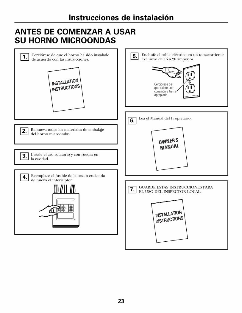
Cerciórese de que existe unaconexión a tierraapropiada
23
GUARDE ESTAS INSTRUCCIONES PARAEL USO DEL INSPECTOR LOCAL.
Enchufe el cable eléctrico en un tomacorrienteexclusivo de 15 a 20 amperios.
7.
Lea el Manual del Propietario.6.
Reemplace el fusible de la casa o enciendade nuevo el interruptor.4.
Remueva todos los materiales de embalajedel horno microondas.
2.
Cerciórese de que el horno ha sido instaladode acuerdo con las instrucciones.1.
ANTES DE COMENZAR A USAR SU HORNO MICROONDAS
Instrucciones de instalación
Instale el aro rotatorio y con ruedas en la cavidad.3.
5.

Impreso en Malasia
DE68-03410A49-40558
04-07 JR

![Topic – string – Ch. 11 [Marut] Ch. 4 [Brey] String Data Transfer Instructions – The Direction Flag – LODS Instructions – STOS Instructions – MOVS Instructions](https://img.pdfslide.tips/doc/110x75/56649d895503460f94a6f4e9/topic-string-ch-11-marut-ch-4-brey-string-data-transfer-instructions.jpg)