Embed Size (px)
Citation preview

Instructor Notes:
Generative Shape Optimizer
Copyright DASSAULT SYSTEMES 1
��������������
Cop
yrig
ht D
AS
SA
ULT
SY
STE
ME
S
Generative Shape Optimizer
CATIA V5 TrainingFoils
Version 5 Release 19January 2009
EDU_CAT_EN_GSO_FI_V5R19
Instructor Notes:
Generative Shape Optimizer
Copyright DASSAULT SYSTEMES 2
��������������
Cop
yrig
ht D
AS
SA
ULT
SY
STE
ME
S
About this courseObjectives of the courseUpon completion of the course you will learn to:- Develop Shapes- Morph Shapes- Create Junctions (BIW application) between surfaces- Work with Volumes
Targeted audienceSurface Designers
PrerequisitesStudents attending this course should have knowledge of:CATIA Surface Design.
8 hrs
Instructor Notes:
Generative Shape Optimizer
Copyright DASSAULT SYSTEMES 3
��������������
Cop
yrig
ht D
AS
SA
ULT
SY
STE
ME
S
Table of Contents (1/2)
Introduction to Generative Shape Design Optimizer 5Accessing Generative Shape Design Optimizer Workbench 6The User Interface 7
Creating Offset Surfaces 8Creating Variable Offsets 9Creating Rough Offsets 13
Developing Shapes 16What is Developing a Wire 17Developing Wires 18Additional Information on Developing Wire 20
Using BIW Tools 22Creating Junctions 23How to Create a Diabolo Seat 28
Creating Advanced Surfaces 29How to Create a Bumped Surface 30Deforming Surfaces by Wrapping Curve 33How to Create a Wrap Surface 37How to Morph a Shape 38
Instructor Notes:
Generative Shape Optimizer
Copyright DASSAULT SYSTEMES 4
��������������
Cop
yrig
ht D
AS
SA
ULT
SY
STE
ME
S
Table of Contents (2/2)
How to Morph a Shape: Limit Curve 39
Creating Advanced Operations 40What is an Auto Fillet? 41Auto Fillet User Interface 42How to Create an Auto Fillet 45
Creating Volumes 46What is a Volume ? 47Different types of volumes 48Volumes Made From Sketches 49Creating Volumes From Surfaces 57Applying Dress-up Features on Volumes 62Transformations and Operations on Volumes 65Performing Boolean Operations on Volumes 70To Sum Up 76
Generative Shape Design Optimizer Exercises 77Door Junction Exercise 78Holding Arm - Volumes Exercise 1 83Torch – Volumes Exercise 2 84Steering Wheel Exercise 85
Instructor Notes:
Generative Shape Optimizer
Copyright DASSAULT SYSTEMES 5
��������������
Cop
yrig
ht D
AS
SA
ULT
SY
STE
ME
S
Introduction to Generative Shape Design OptimizerIn this lesson you will be introduced to the working environment of Generative Shape Design Optimizer Workbench.
Accessing Generative Shape Design Optimizer WorkbenchThe User Interface
Instructor Notes:
Generative Shape Optimizer
Copyright DASSAULT SYSTEMES 6
��������������
Cop
yrig
ht D
AS
SA
ULT
SY
STE
ME
S
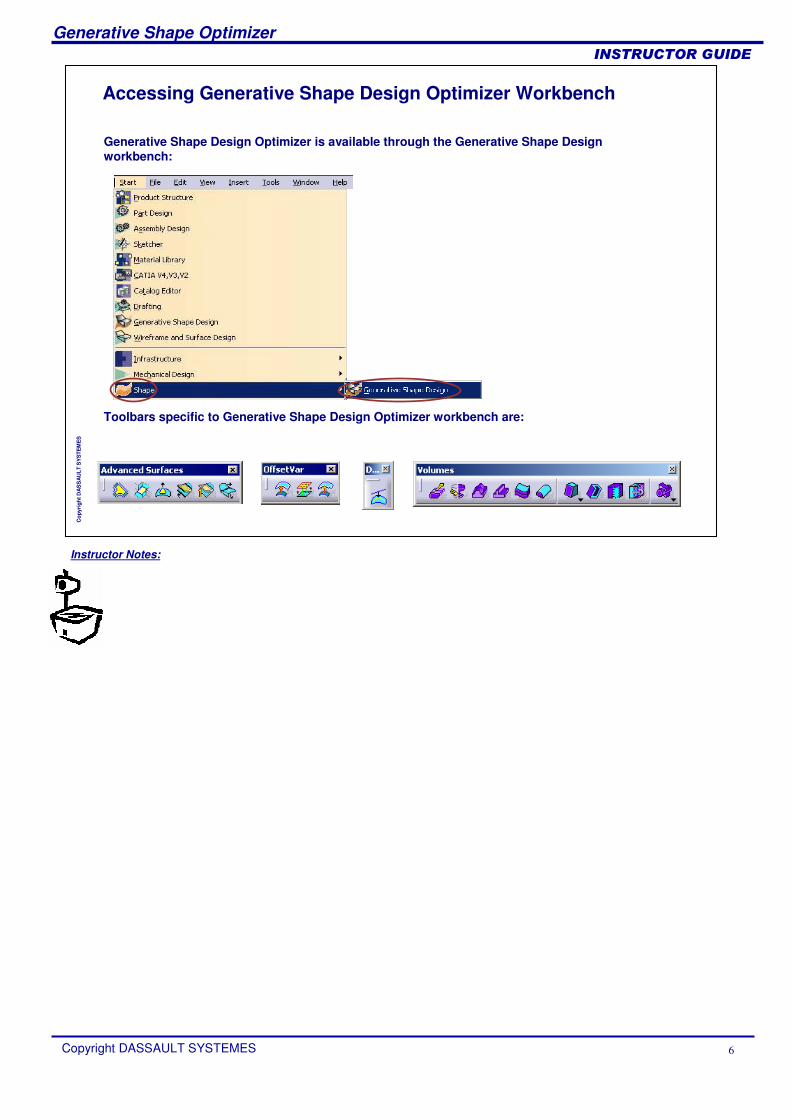
Accessing Generative Shape Design Optimizer Workbench
Generative Shape Design Optimizer is available through the Generative Shape Design workbench:
Toolbars specific to Generative Shape Design Optimizer workbench are:
Instructor Notes:
Generative Shape Optimizer
Copyright DASSAULT SYSTEMES 7
��������������
Cop
yrig
ht D
AS
SA
ULT
SY
STE
ME
S
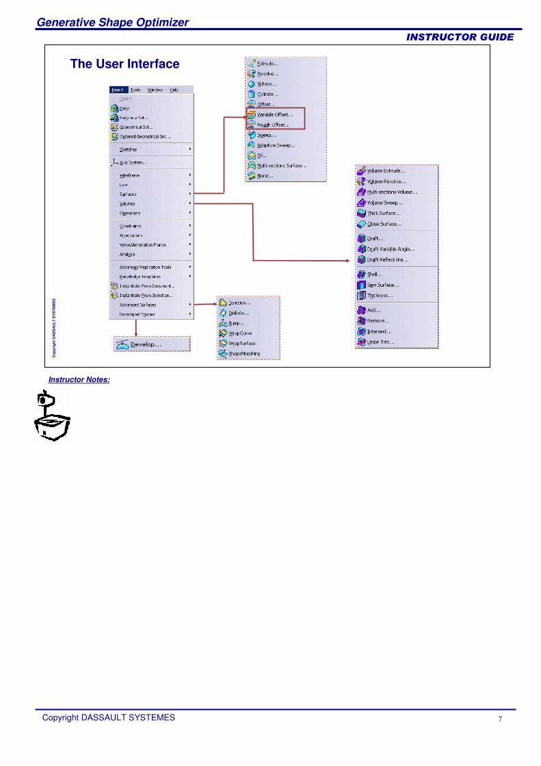
The User Interface
Instructor Notes:
Generative Shape Optimizer
Copyright DASSAULT SYSTEMES 8
��������������
Cop
yrig
ht D
AS
SA
ULT
SY
STE
ME
S
Creating Offset SurfacesIn this lesson, you will learn how to create offsets.
Creating Variable OffsetsCreating Rough Offsets
Instructor Notes:
Generative Shape Optimizer
Copyright DASSAULT SYSTEMES 9
��������������
Cop
yrig
ht D
AS
SA
ULT
SY
STE
ME
S
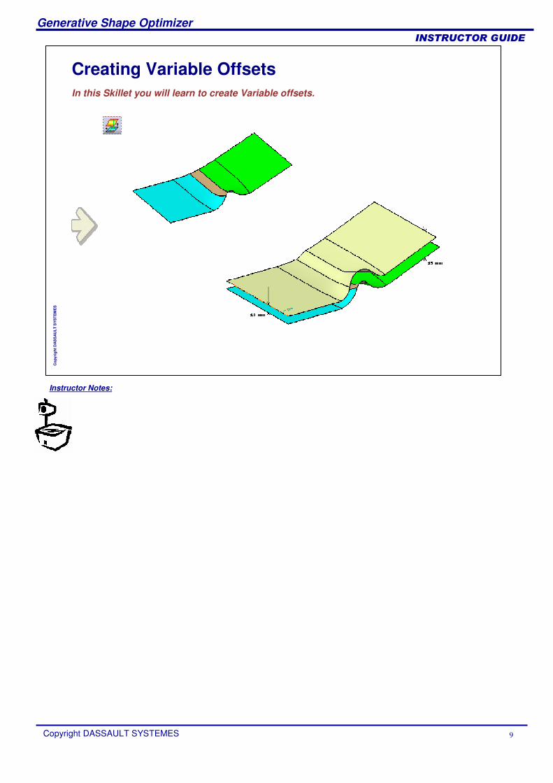
Creating Variable OffsetsIn this Skillet you will learn to create Variable offsets.
Instructor Notes:
Generative Shape Optimizer
Copyright DASSAULT SYSTEMES 10
��������������
Cop
yrig
ht D
AS
SA
ULT
SY
STE
ME
S
What is Variable Offset
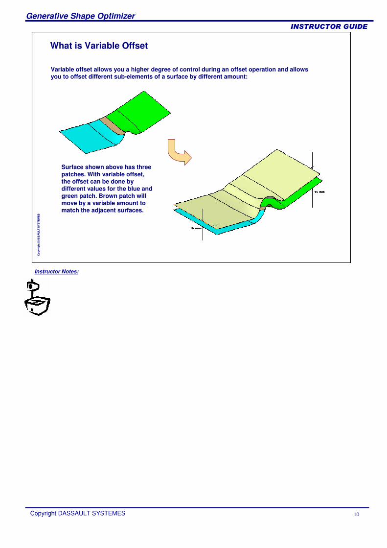
Variable offset allows you a higher degree of control during an offset operation and allows you to offset different sub-elements of a surface by different amount:
Surface shown above has three patches. With variable offset, the offset can be done by different values for the blue and green patch. Brown patch will move by a variable amount to match the adjacent surfaces.
Instructor Notes:
Generative Shape Optimizer
Copyright DASSAULT SYSTEMES 11
��������������
Cop
yrig
ht D
AS
SA
ULT
SY
STE
ME
S
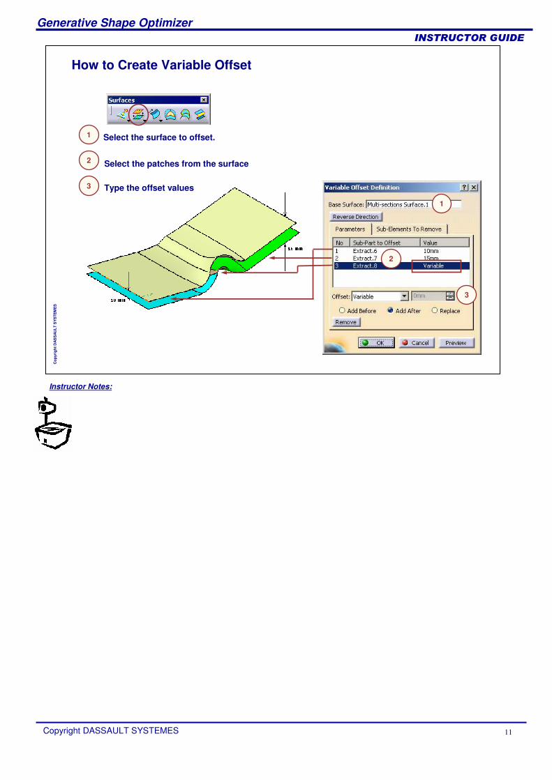
How to Create Variable Offset
1
2
3
Select the surface to offset.
Select the patches from the surface
Type the offset values
1
2
3
Instructor Notes:
Generative Shape Optimizer
Copyright DASSAULT SYSTEMES 12
��������������
Cop
yrig
ht D
AS
SA
ULT
SY
STE
ME
S
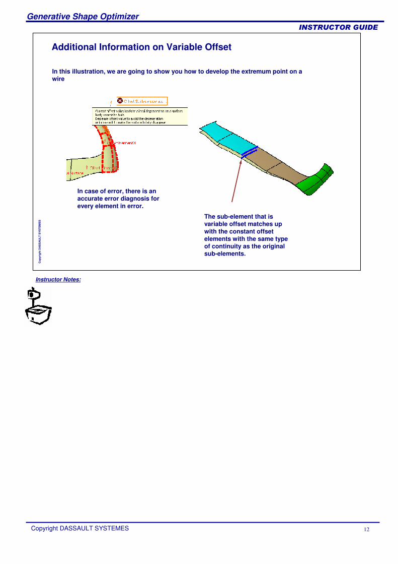
Additional Information on Variable Offset
In this illustration, we are going to show you how to develop the extremum point on a wire
In case of error, there is an accurate error diagnosis for every element in error.
The sub-element that is variable offset matches up with the constant offset elements with the same type of continuity as the original sub-elements.
Instructor Notes:
Generative Shape Optimizer
Copyright DASSAULT SYSTEMES 13
��������������
Cop
yrig
ht D
AS
SA
ULT
SY
STE
ME
S
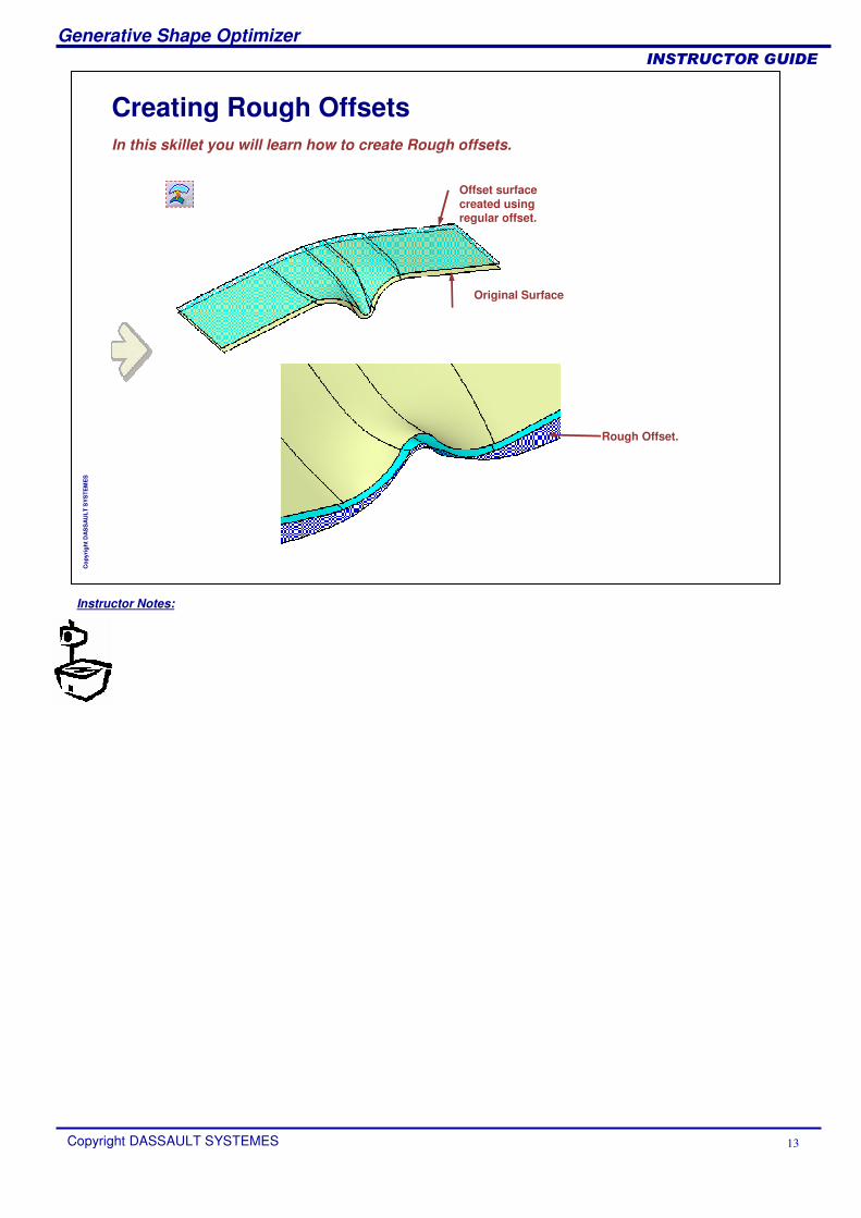
Creating Rough OffsetsIn this skillet you will learn how to create Rough offsets.
Offset surface created using regular offset.
Original Surface
Rough Offset.
Instructor Notes:
Generative Shape Optimizer
Copyright DASSAULT SYSTEMES 14
��������������
Cop
yrig
ht D
AS
SA
ULT
SY
STE
ME
S
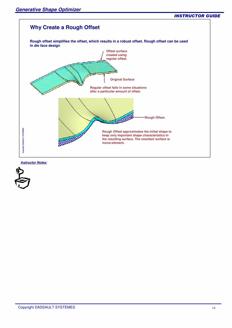
Why Create a Rough Offset
Offset surface created using regular offset.
Original Surface
Regular offset fails in some situations after a particular amount of offset.
Rough Offset.
Rough Offset approximates the initial shape to keep only important shape characteristics in the resulting surface. The resultant surface is mono-element.
Rough offset simplifies the offset, which results in a robust offset. Rough offset can be used in die face design

Instructor Notes:
Generative Shape Optimizer
Copyright DASSAULT SYSTEMES 15
��������������
Cop
yrig
ht D
AS
SA
ULT
SY
STE
ME
S
How to Create a Rough Offset
The Deviation parameter is a driving parameter for the approximation. Therefore, the higher the deviation, the higher the approximation and the smoother the result is produced.
1
2
3
Click the icon
Type Offset value
2
3
4
1
4 Type Deviation
Select the surface to offset
Instructor Notes:
Generative Shape Optimizer
Copyright DASSAULT SYSTEMES 16
��������������
Cop
yrig
ht D
AS
SA
ULT
SY
STE
ME
S
Developing ShapesIn this lesson, you will learn how to develop wires using the Generative Shape Design Optimizer workbench.
What is Developing a WireDeveloping WiresAdditional Information on Developing Wire

Instructor Notes:
Generative Shape Optimizer
Copyright DASSAULT SYSTEMES 17
��������������
Cop
yrig
ht D
AS
SA
ULT
SY
STE
ME
S
What is Developing a Wire
Wire to develop
Support surface
Origin point on support
Developing Wire allows you to develop a wire lying on a plane into a revolution surface
Load:Develop_plane-revol.CATPart
Instructor Notes:
Generative Shape Optimizer
Copyright DASSAULT SYSTEMES 18
��������������
Cop
yrig
ht D
AS
SA
ULT
SY
STE
ME
S
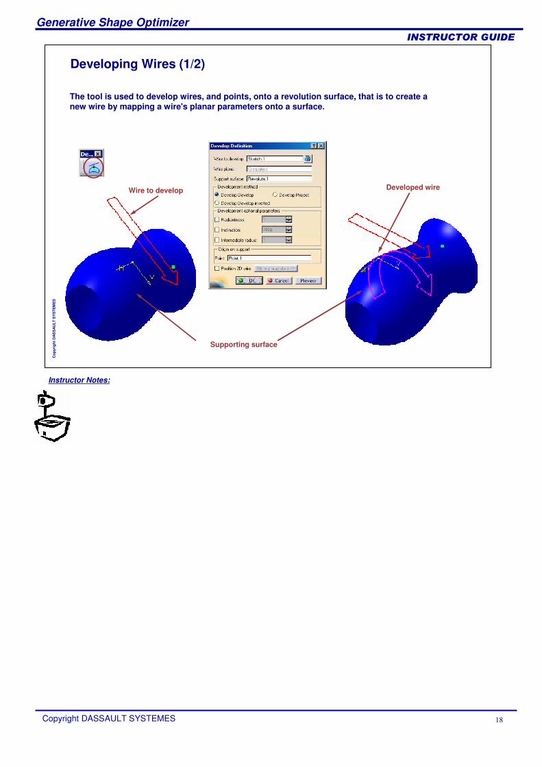
Developing Wires (1/2)
Wire to develop
Supporting surface
The tool is used to develop wires, and points, onto a revolution surface, that is to create a new wire by mapping a wire's planar parameters onto a surface.
Developed wire
Instructor Notes:
Generative Shape Optimizer
Copyright DASSAULT SYSTEMES 19
��������������
Cop
yrig
ht D
AS
SA
ULT
SY
STE
ME
S
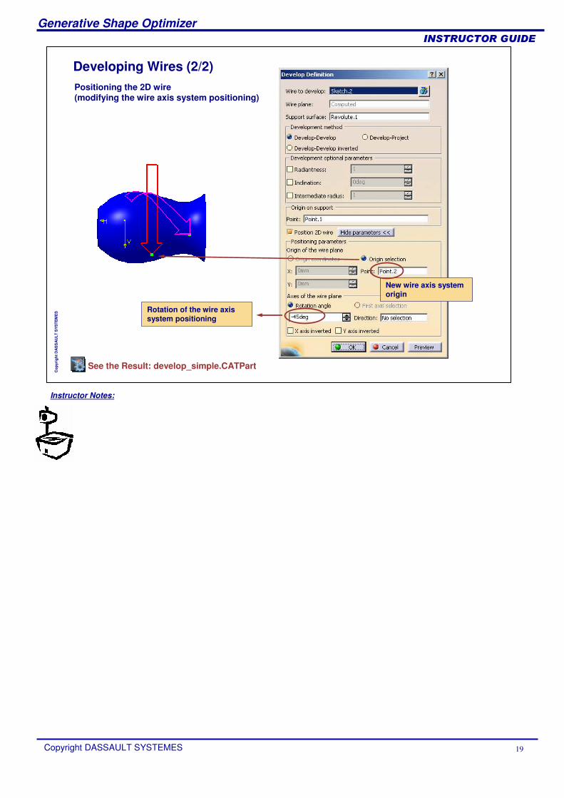
Developing Wires (2/2)Positioning the 2D wire (modifying the wire axis system positioning)
Rotation of the wire axis system positioning
New wire axis system origin
See the Result: develop_simple.CATPart
Instructor Notes:
Generative Shape Optimizer
Copyright DASSAULT SYSTEMES 20
��������������
Cop
yrig
ht D
AS
SA
ULT
SY
STE
ME
S
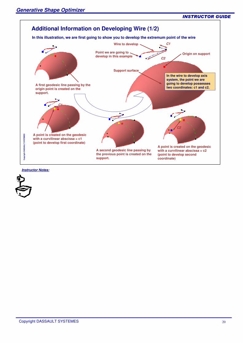
Additional Information on Developing Wire (1/2)In this illustration, we are first going to show you to develop the extremum point of the wire
C1
C2
Support surface
Origin on support
Wire to develop
A first geodesic line passing by the origin point is created on the support.
In the wire to develop axis system, the point we are going to develop possesses two coordinates: c1 and c2.
A point is created on the geodesic with a curvilinear abscissa = c1 (point to develop first coordinate)
Point we are going to develop in this example
C1
C2
A second geodesic line passing by the previous point is created on the support.
A point is created on the geodesic with a curvilinear abscissa = c2 (point to develop second coordinate)
Instructor Notes:
Generative Shape Optimizer
Copyright DASSAULT SYSTEMES 21
��������������
Cop
yrig
ht D
AS
SA
ULT
SY
STE
ME
S
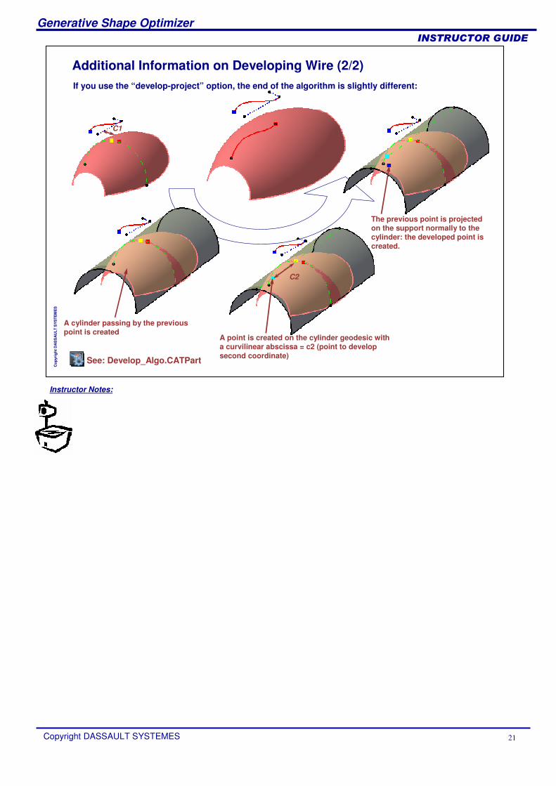
Additional Information on Developing Wire (2/2)If you use the “develop-project” option, the end of the algorithm is slightly different:
C1
C2
A cylinder passing by the previous point is created
A point is created on the cylinder geodesic with a curvilinear abscissa = c2 (point to develop second coordinate)
The previous point is projected on the support normally to the cylinder: the developed point is created.
See: Develop_Algo.CATPart

Instructor Notes:
Generative Shape Optimizer
Copyright DASSAULT SYSTEMES 22
��������������
Cop
yrig
ht D
AS
SA
ULT
SY
STE
ME
S
Using BIW ToolsIn this Lesson you will learn to create Junctions and Diabolo Seat
Creating JunctionsHow to Create a Diabolo Seat
Instructor Notes:
Generative Shape Optimizer
Copyright DASSAULT SYSTEMES 23
��������������
Cop
yrig
ht D
AS
SA
ULT
SY
STE
ME
S
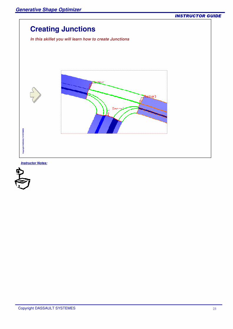
Creating JunctionsIn this skillet you will learn how to create Junctions
Instructor Notes:
Generative Shape Optimizer
Copyright DASSAULT SYSTEMES 24
��������������
Cop
yrig
ht D
AS
SA
ULT
SY
STE
ME
S
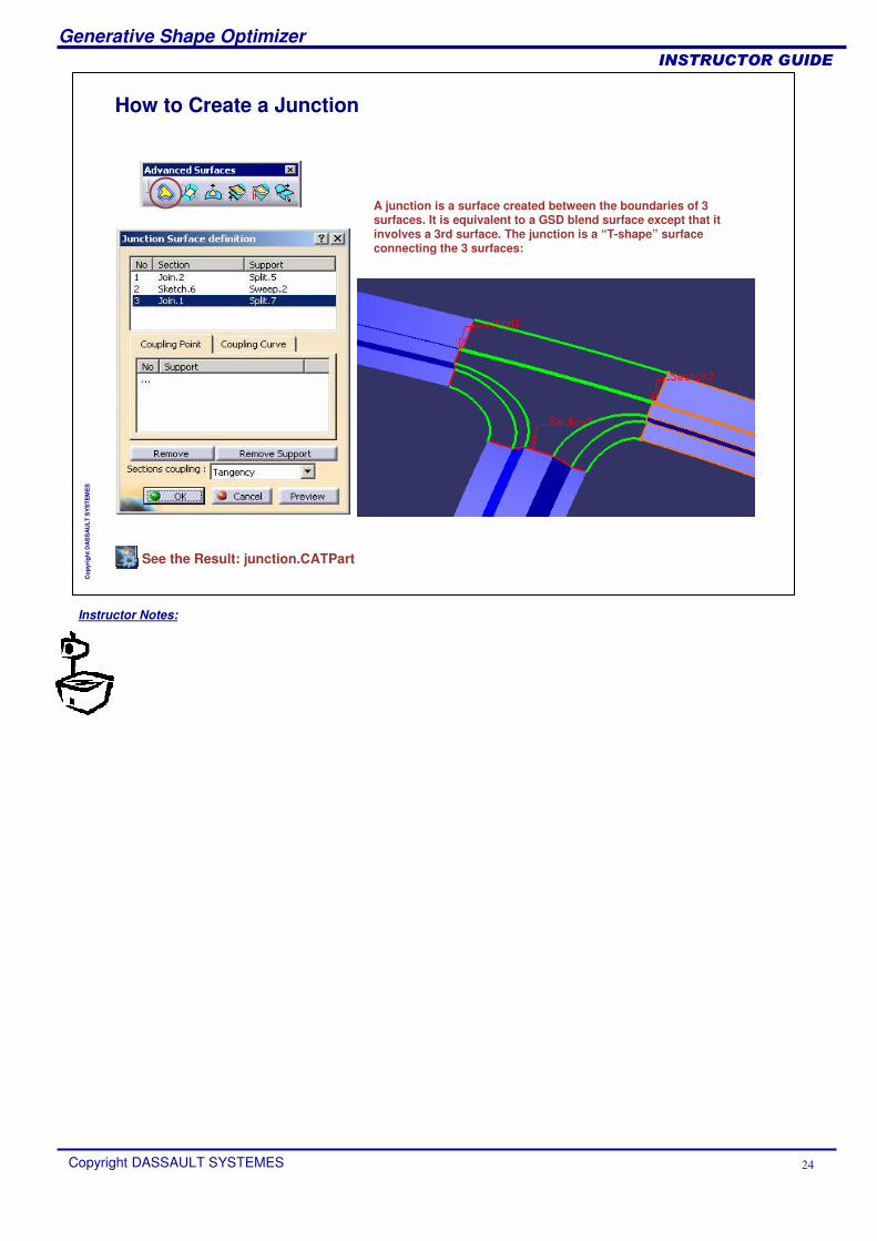
How to Create a Junction
A junction is a surface created between the boundaries of 3 surfaces. It is equivalent to a GSD blend surface except that itinvolves a 3rd surface. The junction is a “T-shape” surface connecting the 3 surfaces:
See the Result: junction.CATPart
Instructor Notes:
Generative Shape Optimizer
Copyright DASSAULT SYSTEMES 25
��������������
Cop
yrig
ht D
AS
SA
ULT
SY
STE
ME
S
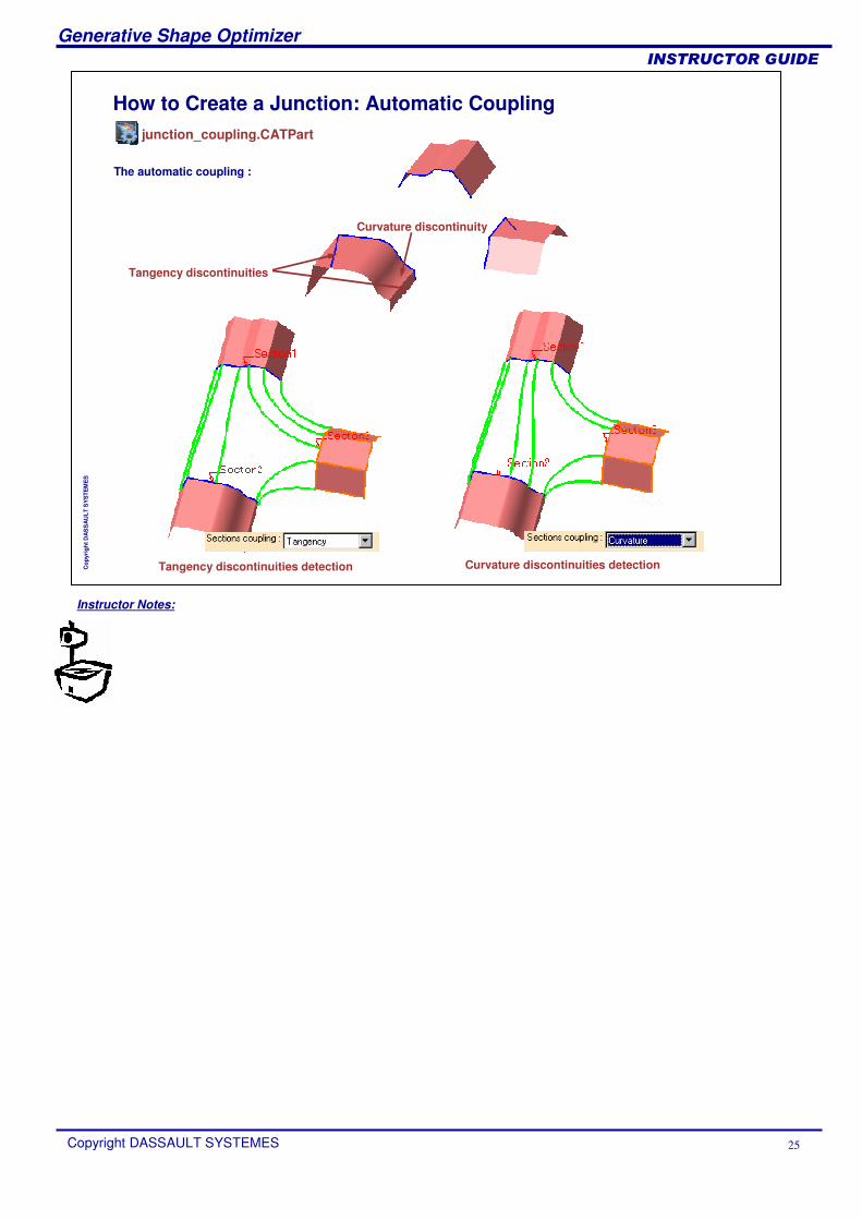
How to Create a Junction: Automatic Coupling
The automatic coupling :
Tangency discontinuities
Curvature discontinuity
Tangency discontinuities detection Curvature discontinuities detection
junction_coupling.CATPart

Instructor Notes:
Generative Shape Optimizer
Copyright DASSAULT SYSTEMES 26
��������������
Cop
yrig
ht D
AS
SA
ULT
SY
STE
ME
S
How to Create a Junction: Manual Coupling (1/2)
The manual coupling : Coupling Point
Coupling points
Load: Junction_Coupling_Point_New.CATPart
Instructor Notes:
Generative Shape Optimizer
Copyright DASSAULT SYSTEMES 27
��������������
Cop
yrig
ht D
AS
SA
ULT
SY
STE
ME
S
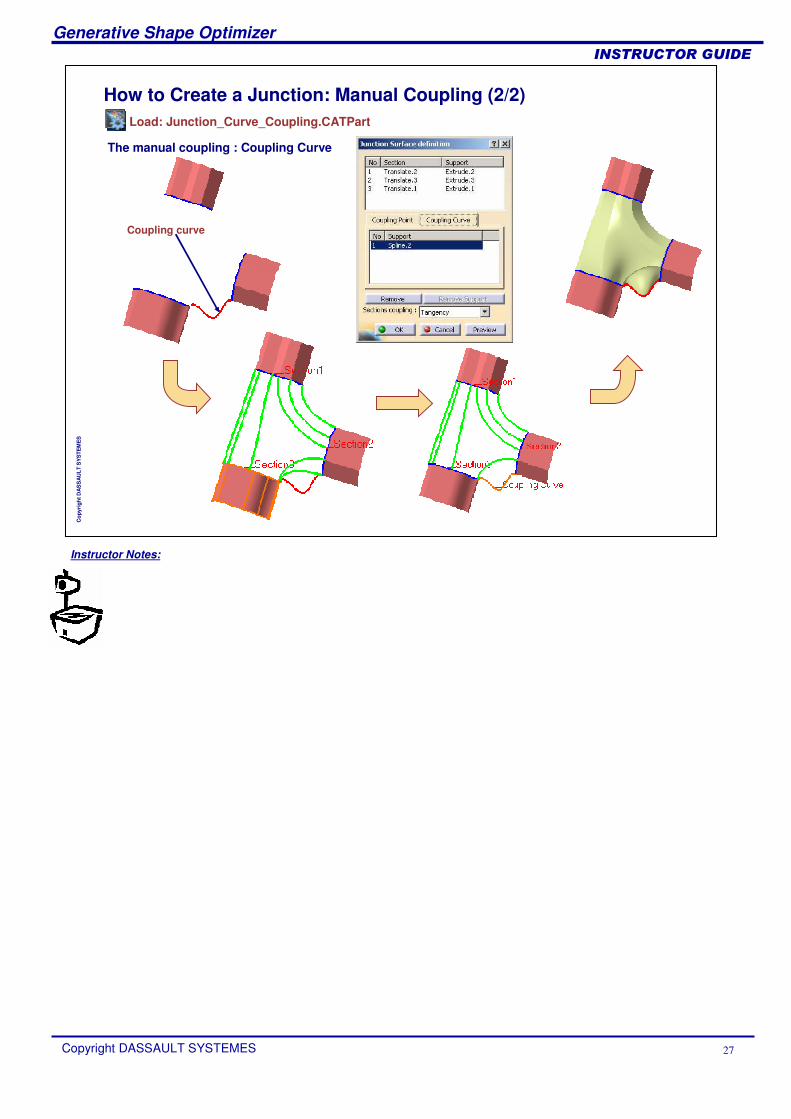
How to Create a Junction: Manual Coupling (2/2)
The manual coupling : Coupling Curve
Coupling curve
Load: Junction_Curve_Coupling.CATPart

Instructor Notes:
Generative Shape Optimizer
Copyright DASSAULT SYSTEMES 28
��������������
Cop
yrig
ht D
AS
SA
ULT
SY
STE
ME
S
How to Create a Diabolo Seat
This tool allows you to create a Diabolo Seat surface including a draft angle:
Base Surface
Seat Surface
Instructor Notes:
Generative Shape Optimizer
Copyright DASSAULT SYSTEMES 29
��������������
Cop
yrig
ht D
AS
SA
ULT
SY
STE
ME
S
Creating Advanced SurfacesIn this lesson you will get familiar with the use of Advanced Surfaces
How to Create a Bumped SurfaceDeforming Surfaces by Wrapping CurveHow to Create a Wrap SurfaceHow to Morph a ShapeHow to Morph a Shape: Limit Curve
Instructor Notes:
Generative Shape Optimizer
Copyright DASSAULT SYSTEMES 30
��������������
Cop
yrig
ht D
AS
SA
ULT
SY
STE
ME
S
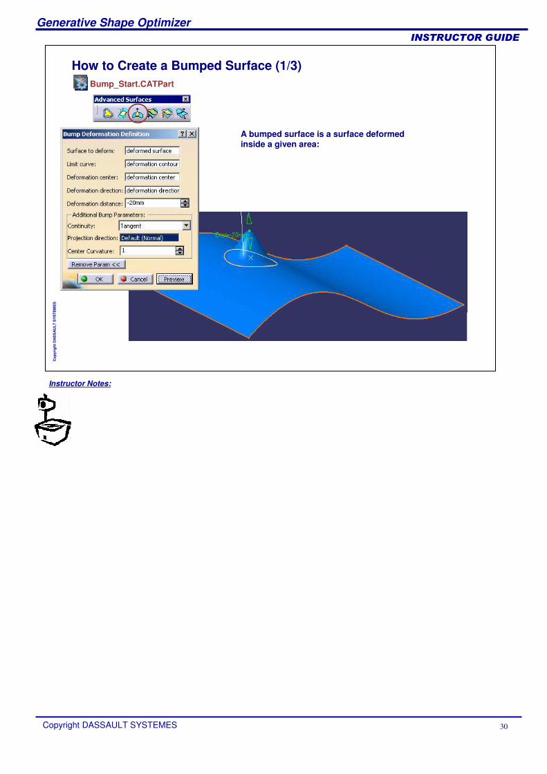
How to Create a Bumped Surface (1/3)
A bumped surface is a surface deformed inside a given area:
Bump_Start.CATPart
Instructor Notes:
Generative Shape Optimizer
Copyright DASSAULT SYSTEMES 31
��������������
Cop
yrig
ht D
AS
SA
ULT
SY
STE
ME
S
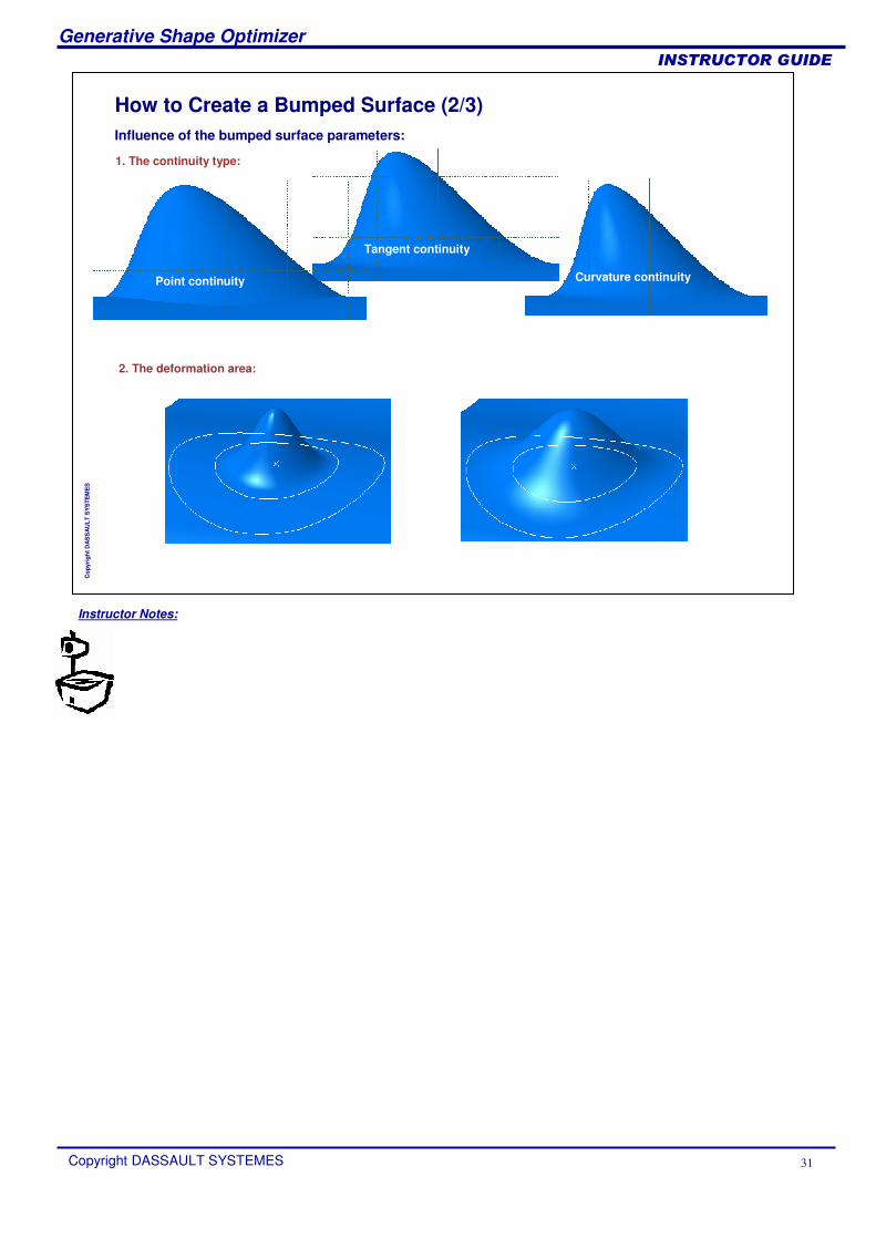
How to Create a Bumped Surface (2/3)Influence of the bumped surface parameters:
1. The continuity type:
Point continuity
Tangent continuity
Curvature continuity
2. The deformation area:
Instructor Notes:
Generative Shape Optimizer
Copyright DASSAULT SYSTEMES 32
��������������
Cop
yrig
ht D
AS
SA
ULT
SY
STE
ME
S
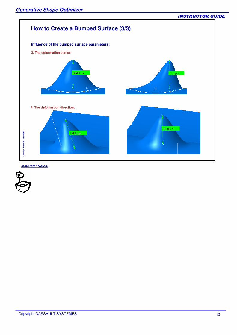
How to Create a Bumped Surface (3/3)
Influence of the bumped surface parameters:
3. The deformation center:
4. The deformation direction:
Instructor Notes:
Generative Shape Optimizer
Copyright DASSAULT SYSTEMES 33
��������������
Cop
yrig
ht D
AS
SA
ULT
SY
STE
ME
S
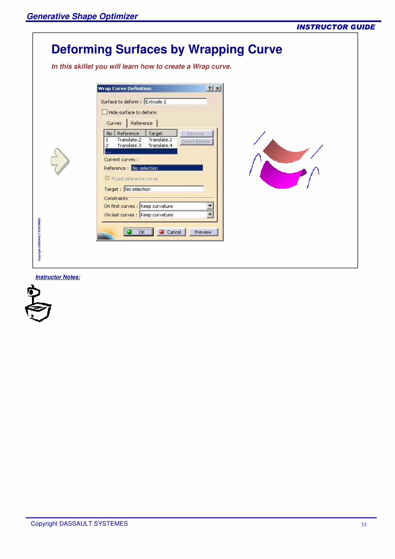
Deforming Surfaces by Wrapping CurveIn this skillet you will learn how to create a Wrap curve.
Instructor Notes:
Generative Shape Optimizer
Copyright DASSAULT SYSTEMES 34
��������������
Cop
yrig
ht D
AS
SA
ULT
SY
STE
ME
S
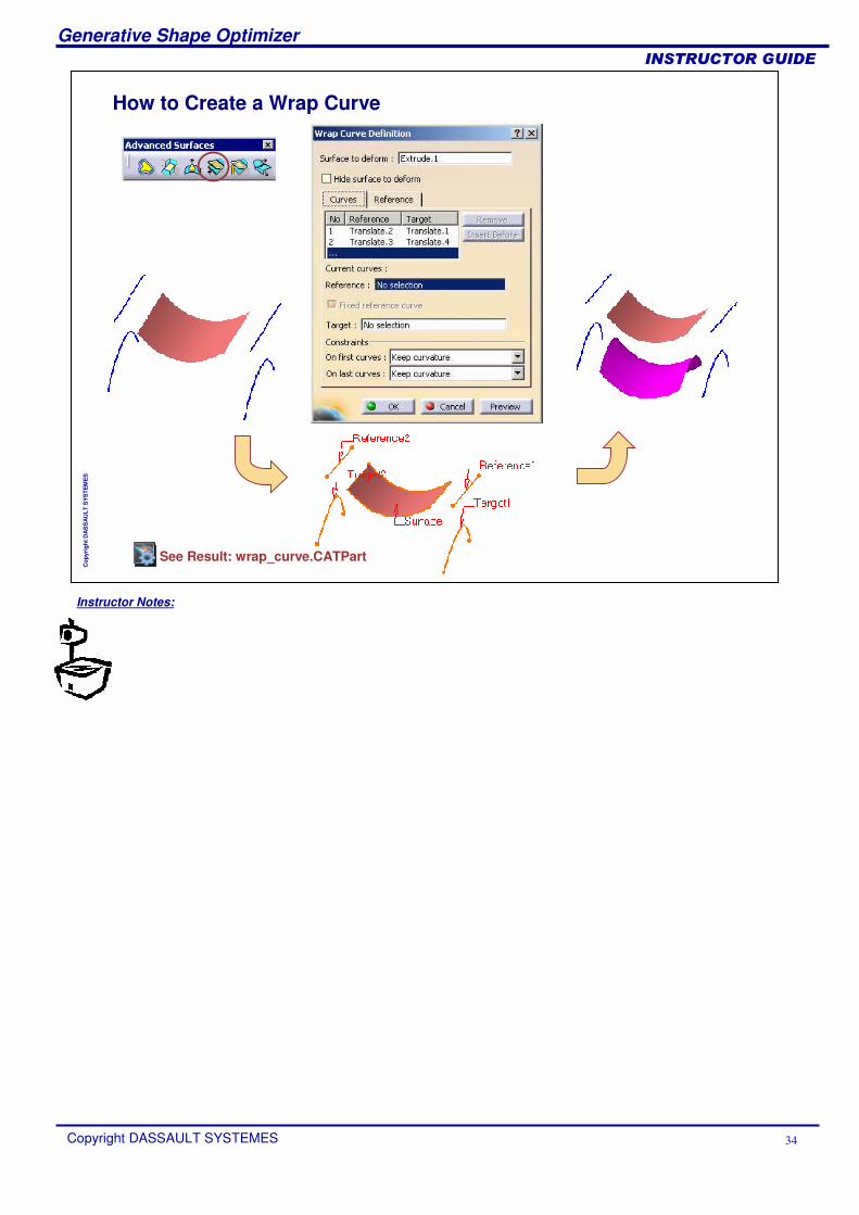
How to Create a Wrap Curve
See Result: wrap_curve.CATPart
Instructor Notes:
Generative Shape Optimizer
Copyright DASSAULT SYSTEMES 35
��������������
Cop
yrig
ht D
AS
SA
ULT
SY
STE
ME
S
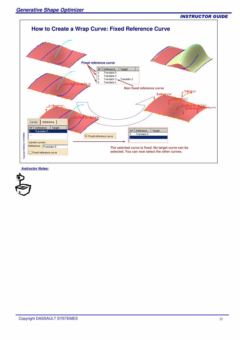
How to Create a Wrap Curve: Fixed Reference Curve
The selected curve is fixed. No target curve can be selected. You can now select the other curves.
Non fixed reference curve
Fixed reference curve
Instructor Notes:
Generative Shape Optimizer
Copyright DASSAULT SYSTEMES 36
��������������
Cop
yrig
ht D
AS
SA
ULT
SY
STE
ME
S
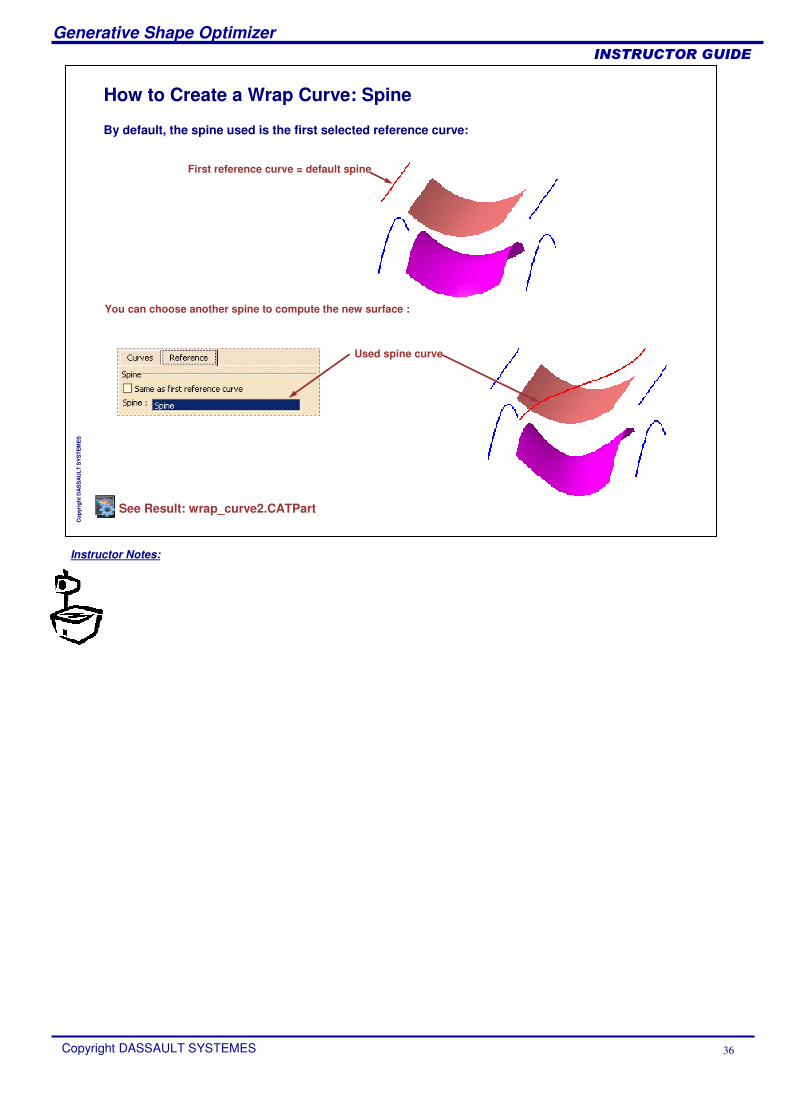
How to Create a Wrap Curve: Spine
By default, the spine used is the first selected reference curve:
First reference curve = default spine
You can choose another spine to compute the new surface :
Used spine curve
See Result: wrap_curve2.CATPart
Instructor Notes:
Generative Shape Optimizer
Copyright DASSAULT SYSTEMES 37
��������������
Cop
yrig
ht D
AS
SA
ULT
SY
STE
ME
S
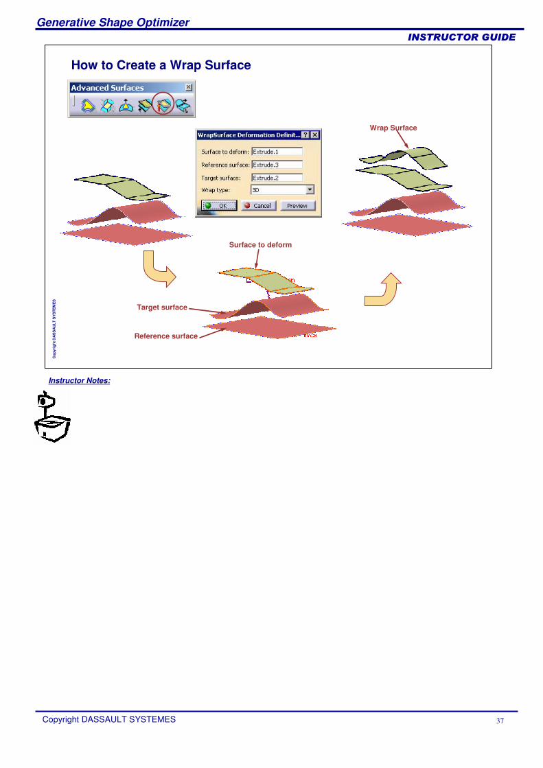
How to Create a Wrap Surface
Reference surface
Surface to deform
Target surface
Wrap Surface
Instructor Notes:
Generative Shape Optimizer
Copyright DASSAULT SYSTEMES 38
��������������
Cop
yrig
ht D
AS
SA
ULT
SY
STE
ME
S
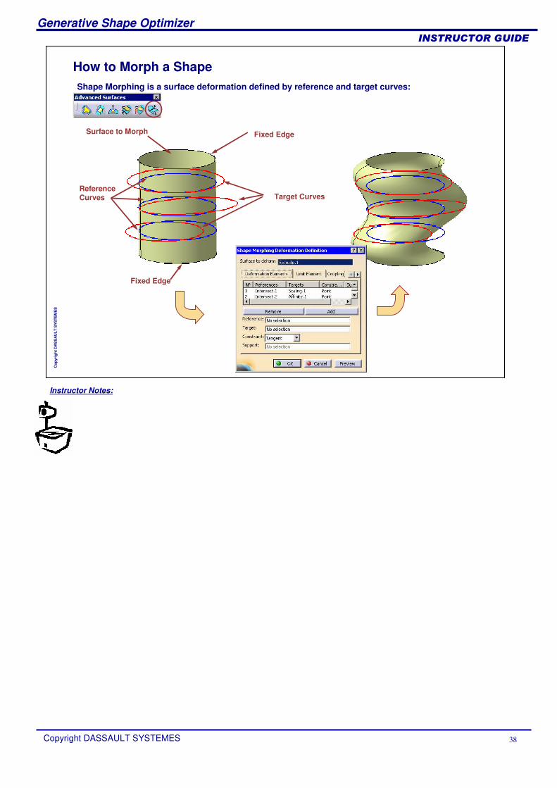
How to Morph a ShapeShape Morphing is a surface deformation defined by reference and target curves:
Reference Curves
Surface to Morph
Target Curves
Fixed Edge
Fixed Edge
Instructor Notes:
Generative Shape Optimizer
Copyright DASSAULT SYSTEMES 39
��������������
Cop
yrig
ht D
AS
SA
ULT
SY
STE
ME
S
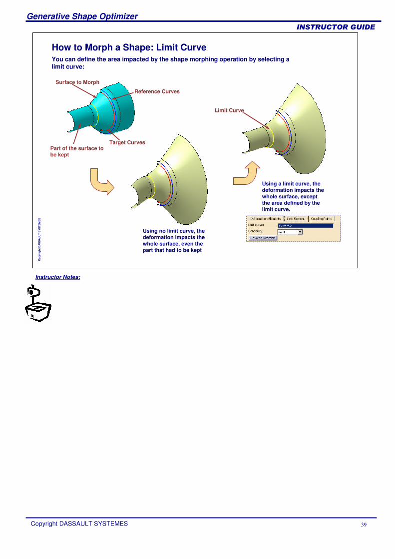
How to Morph a Shape: Limit CurveYou can define the area impacted by the shape morphing operation by selecting a limit curve:
Reference Curves
Surface to Morph
Target CurvesPart of the surface to be kept
Using no limit curve, the deformation impacts the whole surface, even the part that had to be kept
Limit Curve
Using a limit curve, the deformation impacts the whole surface, except the area defined by the limit curve.

Instructor Notes:
Generative Shape Optimizer
Copyright DASSAULT SYSTEMES 40
��������������
Cop
yrig
ht D
AS
SA
ULT
SY
STE
ME
S
Creating Advanced OperationsIn this lesson you will get familiar with the use of Advanced Operations
What is an Auto Fillet?Auto Fillet User InterfaceHow to Create an Auto Fillet
Instructor Notes:
Generative Shape Optimizer
Copyright DASSAULT SYSTEMES 41
��������������
Cop
yrig
ht D
AS
SA
ULT
SY
STE
ME
S
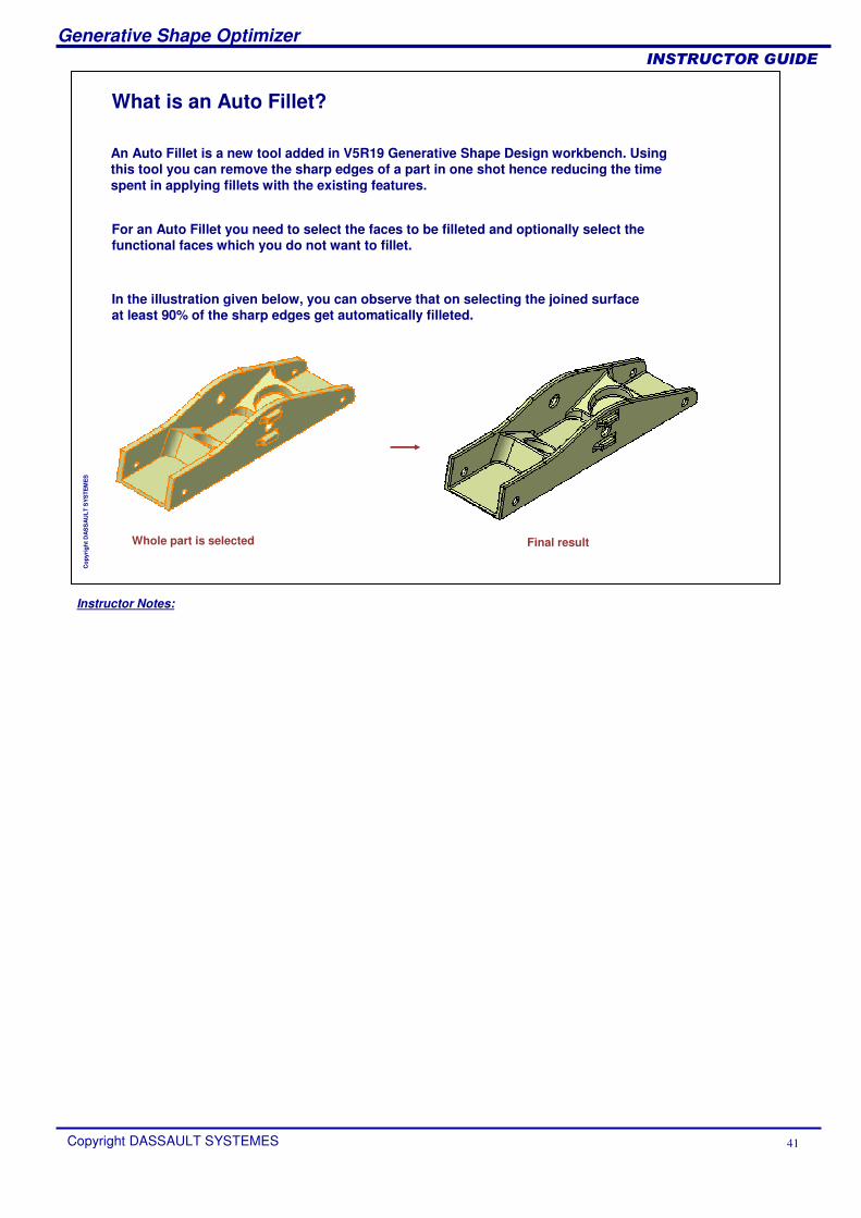
What is an Auto Fillet?
An Auto Fillet is a new tool added in V5R19 Generative Shape Design workbench. Using this tool you can remove the sharp edges of a part in one shot hence reducing the time spent in applying fillets with the existing features.
In the illustration given below, you can observe that on selecting the joined surface at least 90% of the sharp edges get automatically filleted.
For an Auto Fillet you need to select the faces to be filleted and optionally select the functional faces which you do not want to fillet.
Whole part is selected Final result
Instructor Notes:
Generative Shape Optimizer
Copyright DASSAULT SYSTEMES 42
��������������
Cop
yrig
ht D
AS
SA
ULT
SY
STE
ME
S
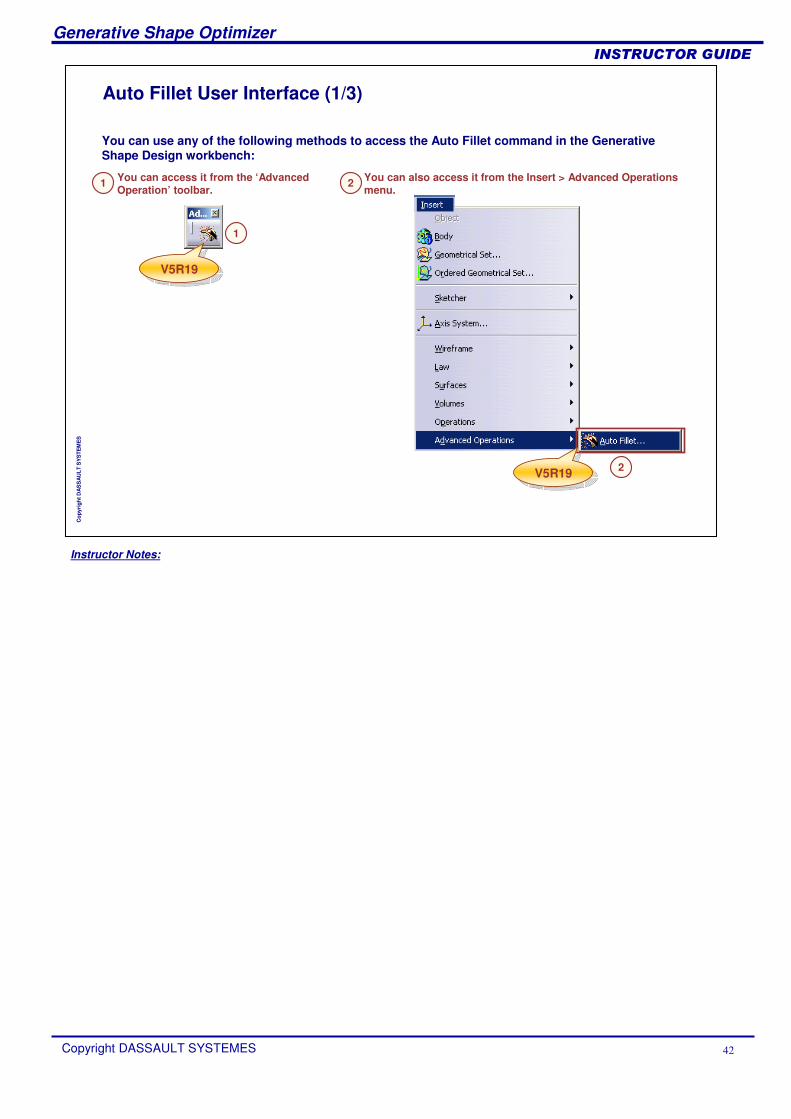
Auto Fillet User Interface (1/3)
You can use any of the following methods to access the Auto Fillet command in the Generative Shape Design workbench:
V5R19V5R19
You can access it from the ‘Advanced Operation’ toolbar.
You can also access it from the Insert > Advanced Operations menu.
V5R19V5R19
1
2
2
1
Instructor Notes:
Generative Shape Optimizer
Copyright DASSAULT SYSTEMES 43
��������������
Cop
yrig
ht D
AS
SA
ULT
SY
STE
ME
S
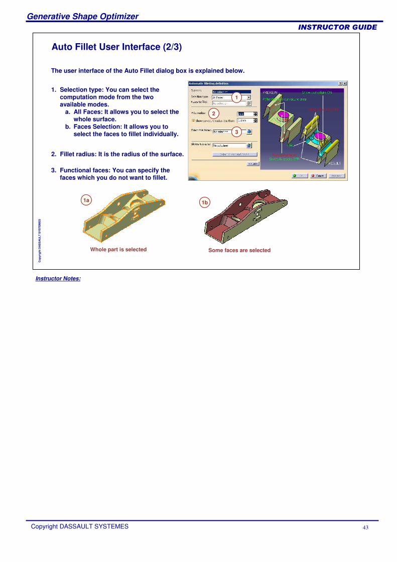
Auto Fillet User Interface (2/3)
The user interface of the Auto Fillet dialog box is explained below.
1. Selection type: You can select the computation mode from the two available modes.
a. All Faces: It allows you to select the whole surface.
b. Faces Selection: It allows you to select the faces to fillet individually.
2. Fillet radius: It is the radius of the surface.
3. Functional faces: You can specify the faces which you do not want to fillet.
1
2
3
1a 1b
Whole part is selected Some faces are selected

Instructor Notes:
Generative Shape Optimizer
Copyright DASSAULT SYSTEMES 44
��������������
Cop
yrig
ht D
AS
SA
ULT
SY
STE
ME
S
Auto Fillet User Interface (3/3)
4. Slivers & cracks:a. Silver: It is an unwanted thin wall
which should be smoothed and partially removed by the automatic filleting operation.
b. Crack: It is an unwanted slot which should be smoothed and partially filled by the automatic filleting operation.
4
4b
4a
Part to Auto fillet Result without silver and crack
Faces selected for silver and crack
Final result
Instructor Notes:
Generative Shape Optimizer
Copyright DASSAULT SYSTEMES 45
��������������
Cop
yrig
ht D
AS
SA
ULT
SY
STE
ME
S
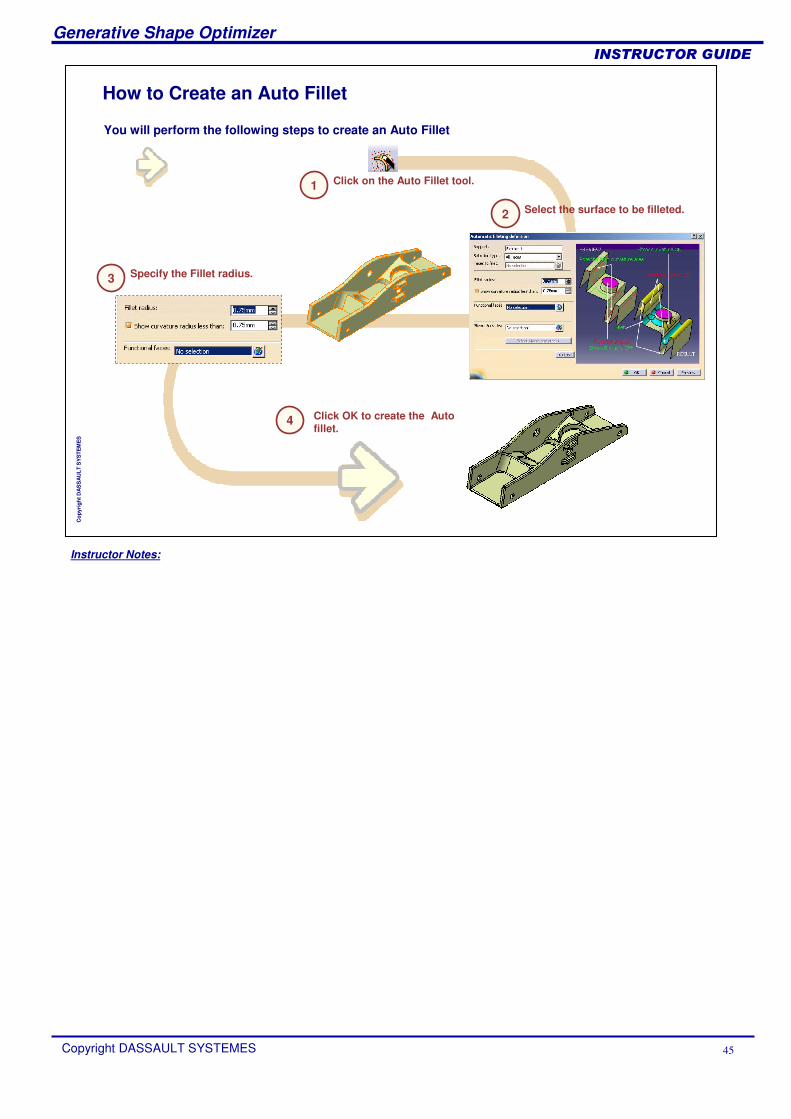
How to Create an Auto Fillet
You will perform the following steps to create an Auto Fillet
1 Click on the Auto Fillet tool.
2 Select the surface to be filleted.
Specify the Fillet radius.3
4 Click OK to create the Auto fillet.
Instructor Notes:
Generative Shape Optimizer
Copyright DASSAULT SYSTEMES 46
��������������
Cop
yrig
ht D
AS
SA
ULT
SY
STE
ME
S
Creating VolumesIn this lesson, you learn how to create Volumes
What is a Volume ?Different types of volumesVolumes Made From SketchesCreating Volumes From SurfacesApplying Dress-up Features on VolumesTransformations and Operations on VolumesPerforming Boolean Operations on VolumesTo Sum Up
Instructor Notes:
Generative Shape Optimizer
Copyright DASSAULT SYSTEMES 47
��������������
Cop
yrig
ht D
AS
SA
ULT
SY
STE
ME
S
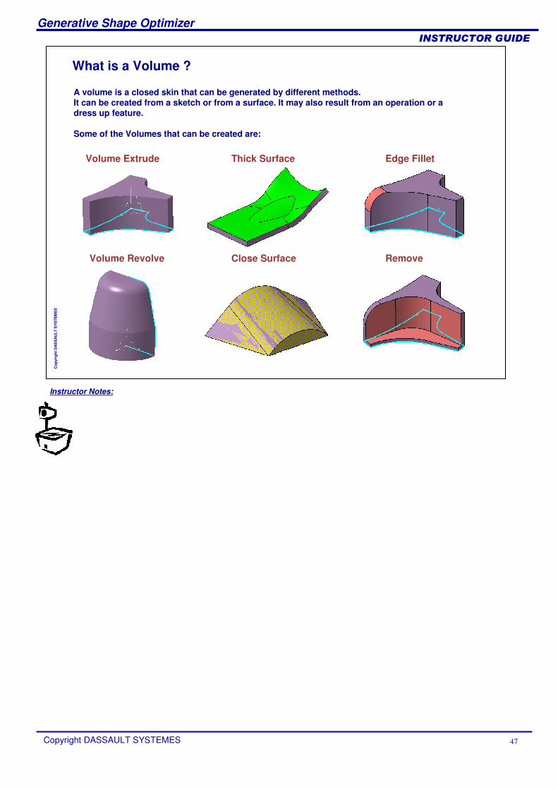
A volume is a closed skin that can be generated by different methods.It can be created from a sketch or from a surface. It may also result from an operation or a dress up feature.
Some of the Volumes that can be created are:
What is a Volume ?
Volume Extrude
Volume Revolve
Thick Surface
Close Surface
Edge Fillet
Remove
Instructor Notes:
Generative Shape Optimizer
Copyright DASSAULT SYSTEMES 48
��������������
Cop
yrig
ht D
AS
SA
ULT
SY
STE
ME
S
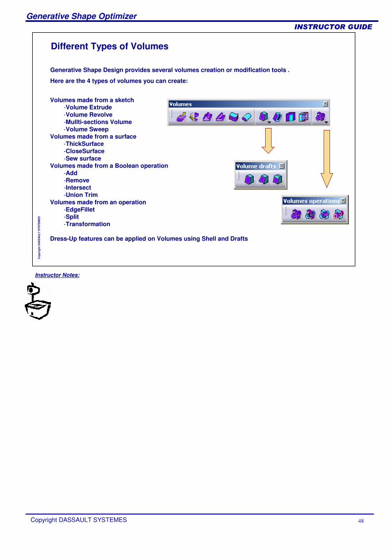
Different Types of Volumes
Volumes made from a sketch -Volume Extrude -Volume Revolve -Mullti-sections Volume -Volume Sweep
Volumes made from a surface -ThickSurface -CloseSurface -Sew surface
Volumes made from a Boolean operation -Add -Remove -Intersect -Union Trim
Volumes made from an operation-EdgeFillet -Split -Transformation
Dress-Up features can be applied on Volumes using Shell and Drafts
Generative Shape Design provides several volumes creation or modification tools .
Here are the 4 types of volumes you can create:
Instructor Notes:
Generative Shape Optimizer
Copyright DASSAULT SYSTEMES 49
��������������
Cop
yrig
ht D
AS
SA
ULT
SY
STE
ME
S
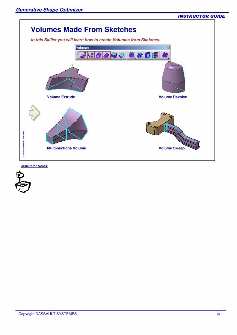
Volumes Made From SketchesIn this Skillet you will learn how to create Volumes from Sketches.
Volume Extrude
Volume SweepMulti-sections Volume
Volume Revolve
Instructor Notes:
Generative Shape Optimizer
Copyright DASSAULT SYSTEMES 50
��������������
Cop
yrig
ht D
AS
SA
ULT
SY
STE
ME
S
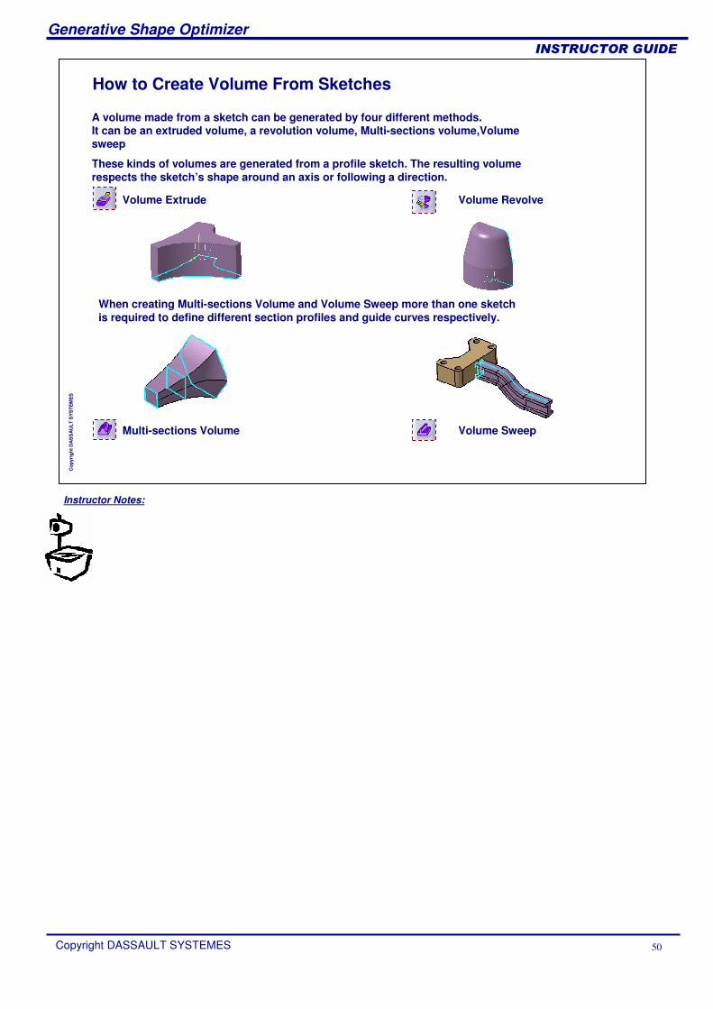
How to Create Volume From Sketches
A volume made from a sketch can be generated by four different methods.It can be an extruded volume, a revolution volume, Multi-sections volume,Volume sweep
These kinds of volumes are generated from a profile sketch. The resulting volume respects the sketch’s shape around an axis or following a direction.
Volume Extrude
Volume SweepMulti-sections Volume
Volume Revolve
When creating Multi-sections Volume and Volume Sweep more than one sketch is required to define different section profiles and guide curves respectively.
Instructor Notes:
Generative Shape Optimizer
Copyright DASSAULT SYSTEMES 51
��������������
Cop
yrig
ht D
AS
SA
ULT
SY
STE
ME
S
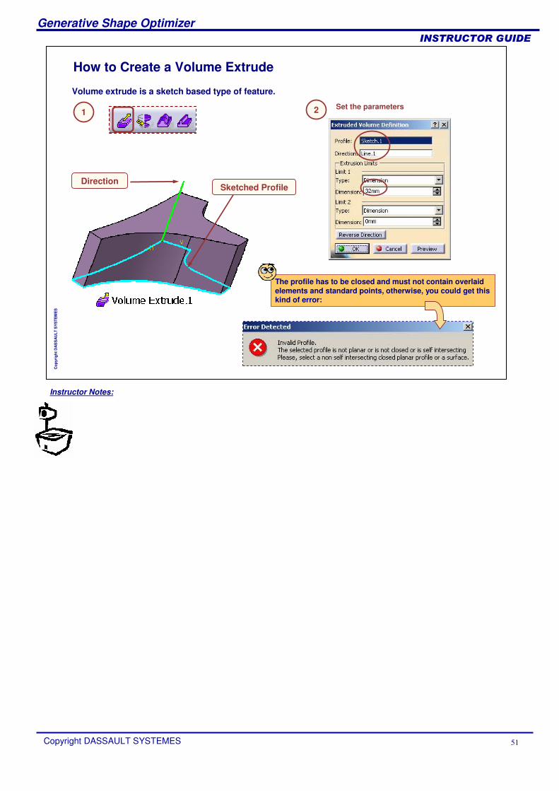
Volume extrude is a sketch based type of feature.
How to Create a Volume Extrude
Set the parameters
Direction
The profile has to be closed and must not contain overlaid elements and standard points, otherwise, you could get this kind of error:
Sketched Profile
1 2
Instructor Notes:
Generative Shape Optimizer
Copyright DASSAULT SYSTEMES 52
��������������
Cop
yrig
ht D
AS
SA
ULT
SY
STE
ME
S
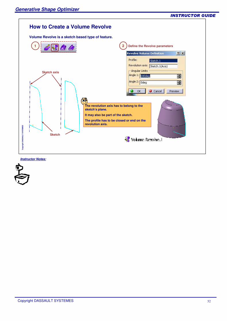
How to Create a Volume Revolve
Define the Revolve parameters
Volume Revolve is a sketch based type of feature.
Sketch
The revolution axis has to belong to the sketch’s plane.
It may also be part of the sketch.
The profile has to be closed or end on the revolution axis.
Sketch axis
1 2
Instructor Notes:
Generative Shape Optimizer
Copyright DASSAULT SYSTEMES 53
��������������
Cop
yrig
ht D
AS
SA
ULT
SY
STE
ME
S
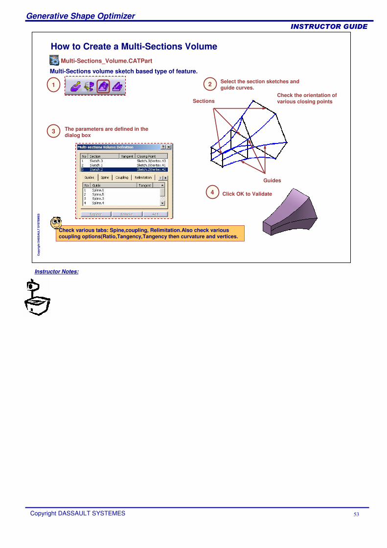
How to Create a Multi-Sections Volume
Select the section sketches and guide curves.
Multi-Sections volume sketch based type of feature.
Guides
Check various tabs: Spine,coupling, Relimitation.Also check various coupling options(Ratio,Tangency,Tangency then curvature and vertices.
Sections
1 2
3 The parameters are defined in the dialog box
4 Click OK to Validate
Check the orientation of various closing points
Multi-Sections_Volume.CATPart
Instructor Notes:
Generative Shape Optimizer
Copyright DASSAULT SYSTEMES 54
��������������
Cop
yrig
ht D
AS
SA
ULT
SY
STE
ME
S
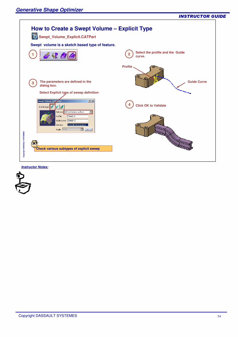
How to Create a Swept Volume – Explicit Type
Select the profile and the Guide curve.
Swept volume is a sketch based type of feature.
Check various subtypes of explicit sweep
Profile
1 2
3 The parameters are defined in the dialog box.
4 Click OK to Validate
Guide Curve
Select Explicit type of sweep definition
Swept_Volume_Explicit.CATPart
Instructor Notes:
Generative Shape Optimizer
Copyright DASSAULT SYSTEMES 55
��������������
Cop
yrig
ht D
AS
SA
ULT
SY
STE
ME
S
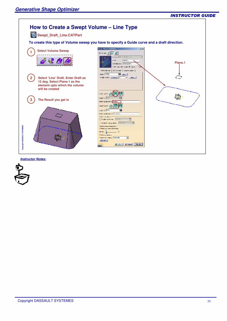
How to Create a Swept Volume – Line Type
To create this type of Volume sweep you have to specify a Guide curve and a draft direction.
1
2 Select ‘Line’ Draft. Enter Draft as 12 deg. Select Plane.1 as the element upto which the volume will be created
Select Volume Sweep
Plane.1
3 The Result you get is
Swept_Draft_Line.CATPart

Instructor Notes:
Generative Shape Optimizer
Copyright DASSAULT SYSTEMES 56
��������������
Cop
yrig
ht D
AS
SA
ULT
SY
STE
ME
S
How to Create a Swept Volume – Circle Type
Select the profile type as circle.
Swept volume is a sketch based type of feature.
Check various subtypes of circle sweep
Center Curve
1 2
3 The parameters are defined in the dialog box.Select Circle sweep.
4 Click OK to Validate
Here S- Type LAW is defined for the Radius value.
Swept_Volume_Circle.CATPart
Instructor Notes:
Generative Shape Optimizer
Copyright DASSAULT SYSTEMES 57
��������������
Cop
yrig
ht D
AS
SA
ULT
SY
STE
ME
S
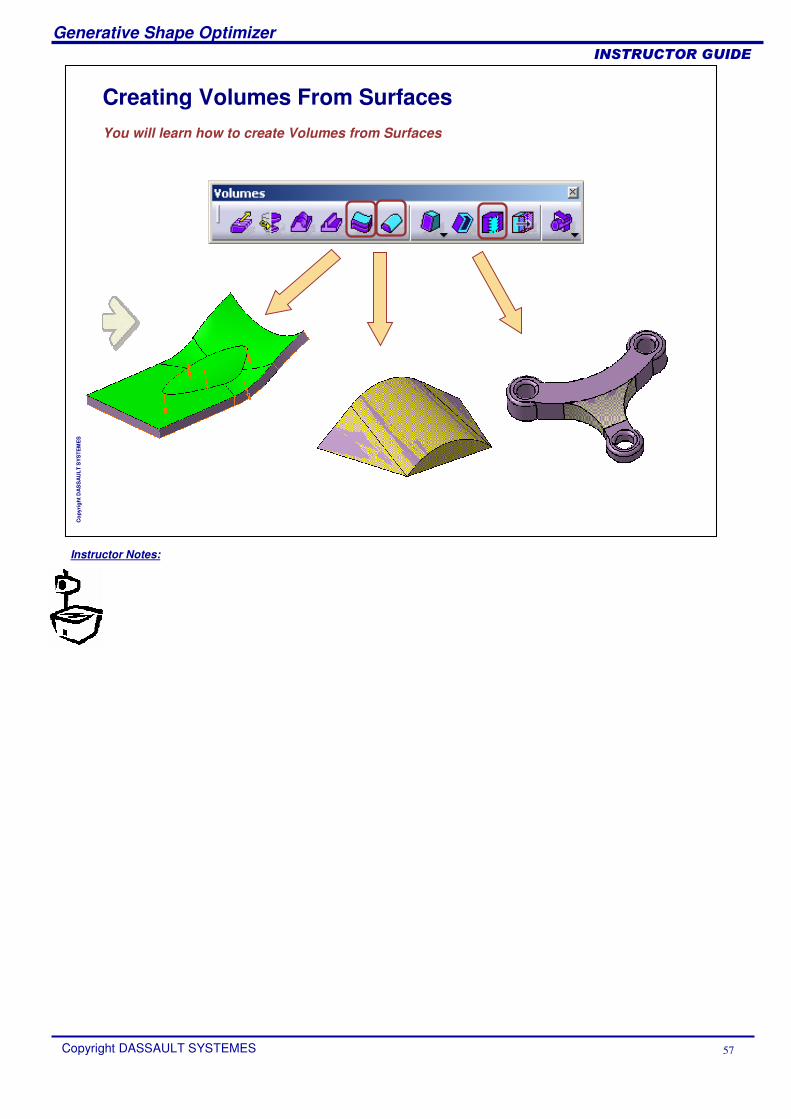
Creating Volumes From SurfacesYou will learn how to create Volumes from Surfaces
Instructor Notes:
Generative Shape Optimizer
Copyright DASSAULT SYSTEMES 58
��������������
Cop
yrig
ht D
AS
SA
ULT
SY
STE
ME
S
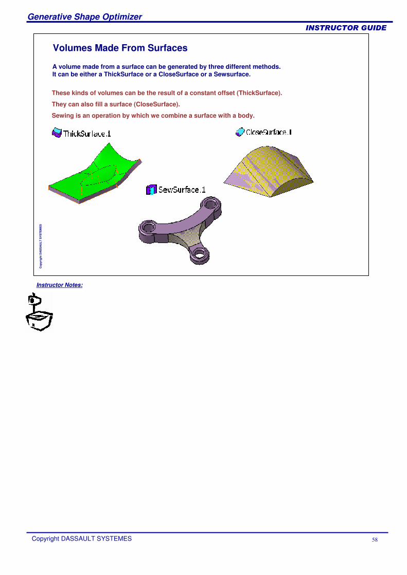
Volumes Made From Surfaces
These kinds of volumes can be the result of a constant offset (ThickSurface).
They can also fill a surface (CloseSurface).
Sewing is an operation by which we combine a surface with a body.
A volume made from a surface can be generated by three different methods.It can be either a ThickSurface or a CloseSurface or a Sewsurface.
Instructor Notes:
Generative Shape Optimizer
Copyright DASSAULT SYSTEMES 59
��������������
Cop
yrig
ht D
AS
SA
ULT
SY
STE
ME
S
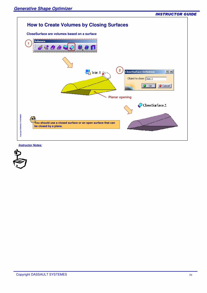
How to Create Volumes by Closing Surfaces
CloseSurface are volumes based on a surface
You should use a closed surface or an open surface that can be closed by a plane.
Planar opening
1
2
Instructor Notes:
Generative Shape Optimizer
Copyright DASSAULT SYSTEMES 60
��������������
Cop
yrig
ht D
AS
SA
ULT
SY
STE
ME
S
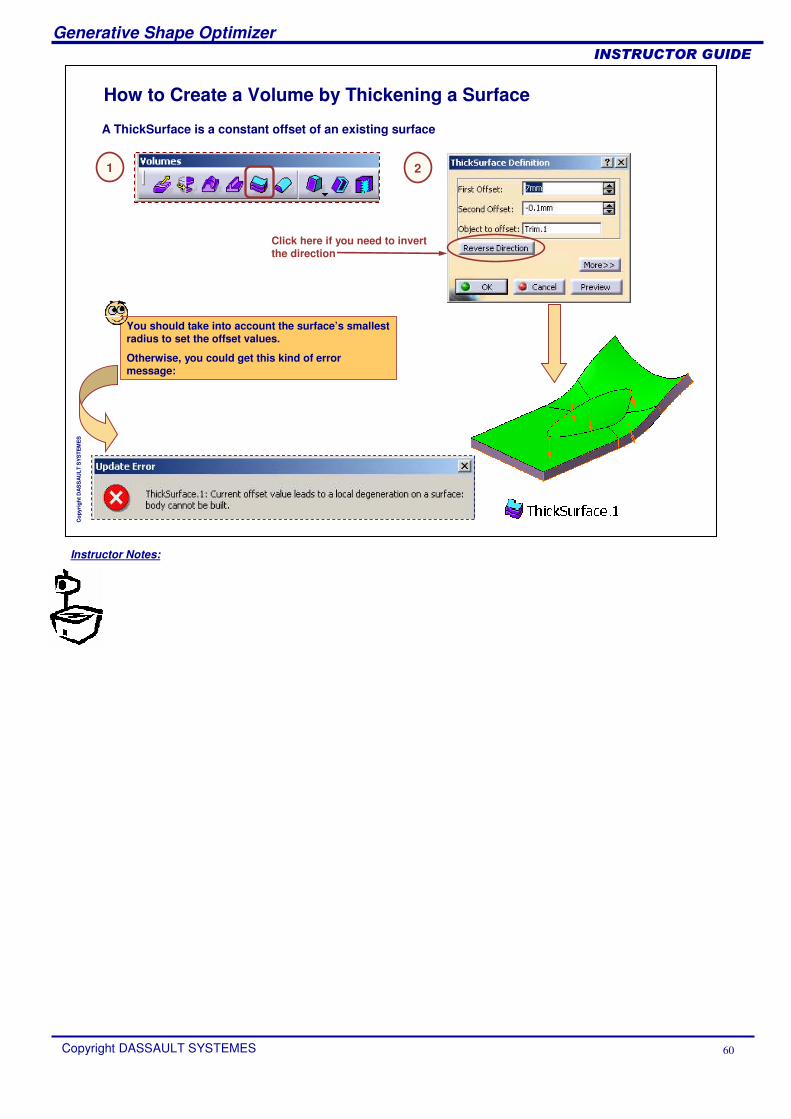
How to Create a Volume by Thickening a Surface
A ThickSurface is a constant offset of an existing surface
You should take into account the surface’s smallest radius to set the offset values.
Otherwise, you could get this kind of error message:
1 2
Click here if you need to invert the direction
Instructor Notes:
Generative Shape Optimizer
Copyright DASSAULT SYSTEMES 61
��������������
Cop
yrig
ht D
AS
SA
ULT
SY
STE
ME
S
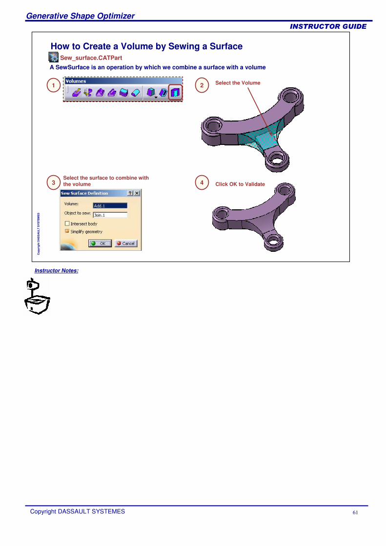
How to Create a Volume by Sewing a Surface
A SewSurface is an operation by which we combine a surface with a volume
1 2 Select the Volume
3Select the surface to combine with the volume 4 Click OK to Validate
Sew_surface.CATPart
Instructor Notes:
Generative Shape Optimizer
Copyright DASSAULT SYSTEMES 62
��������������
Cop
yrig
ht D
AS
SA
ULT
SY
STE
ME
S
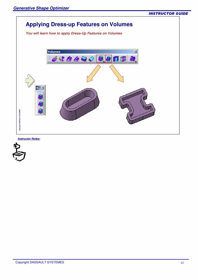
Applying Dress-up Features on VolumesYou will learn how to apply Dress-Up Features on Volumes

Instructor Notes:
Generative Shape Optimizer
Copyright DASSAULT SYSTEMES 63
��������������
Cop
yrig
ht D
AS
SA
ULT
SY
STE
ME
S
How to Apply Draft to a Volume
Drafts are defined on molded parts to make them easier to remove from molds
1 2 Select the faces to be drafted
3 Enter the parameters
Draft_Volume.CATPart
Instructor Notes:
Generative Shape Optimizer
Copyright DASSAULT SYSTEMES 64
��������������
Cop
yrig
ht D
AS
SA
ULT
SY
STE
ME
S
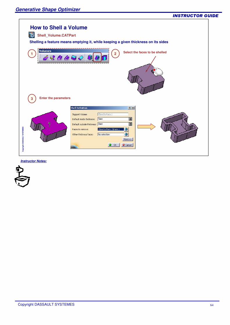
How to Shell a Volume
Shelling a feature means emptying it, while keeping a given thickness on its sides
1 2 Select the faces to be shelled
3 Enter the parameters
Shell_Volume.CATPart
Instructor Notes:
Generative Shape Optimizer
Copyright DASSAULT SYSTEMES 65
��������������
Cop
yrig
ht D
AS
SA
ULT
SY
STE
ME
S
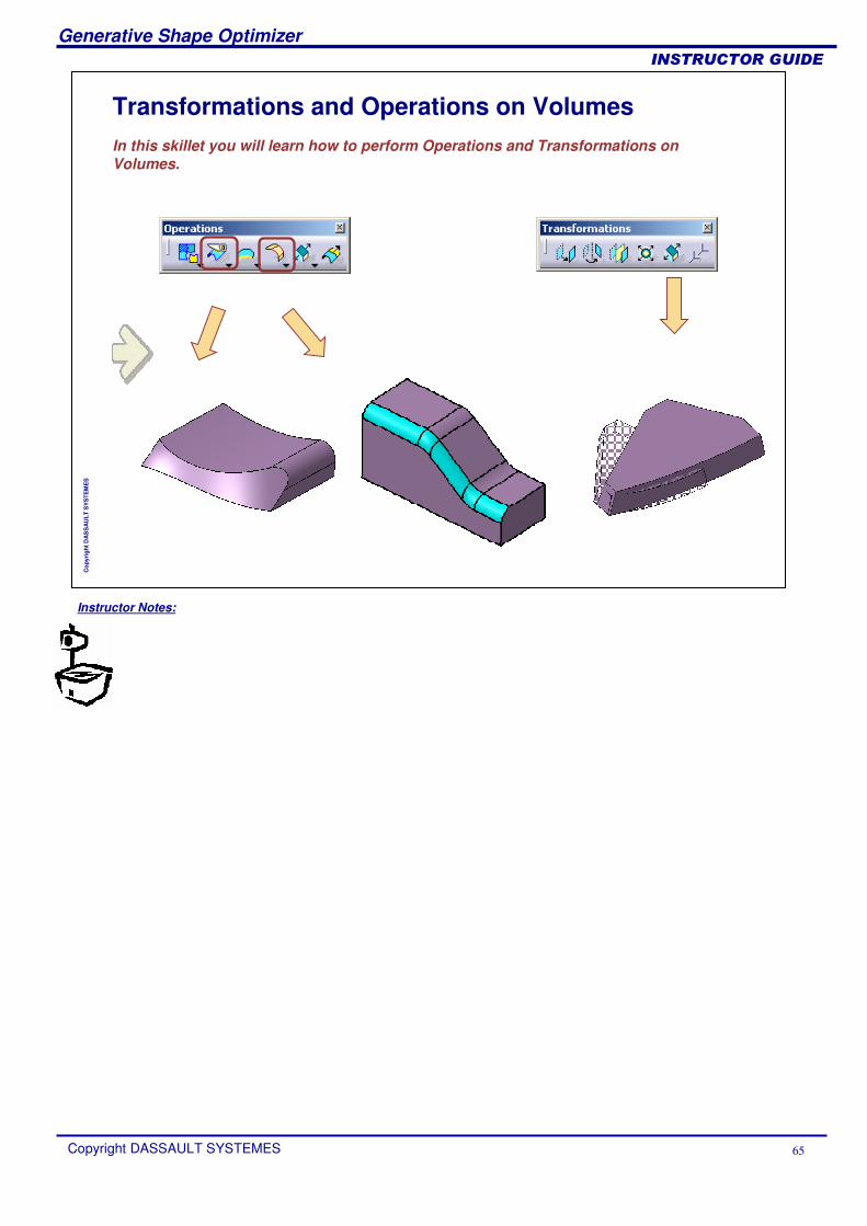
Transformations and Operations on VolumesIn this skillet you will learn how to perform Operations and Transformations on Volumes.
Instructor Notes:
Generative Shape Optimizer
Copyright DASSAULT SYSTEMES 66
��������������
Cop
yrig
ht D
AS
SA
ULT
SY
STE
ME
S
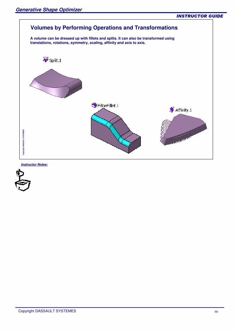
Volumes by Performing Operations and Transformations
A volume can be dressed up with fillets and splits. It can also be transformed using translations, rotations, symmetry, scaling, affinity and axis to axis.
Instructor Notes:
Generative Shape Optimizer
Copyright DASSAULT SYSTEMES 67
��������������
Cop
yrig
ht D
AS
SA
ULT
SY
STE
ME
S
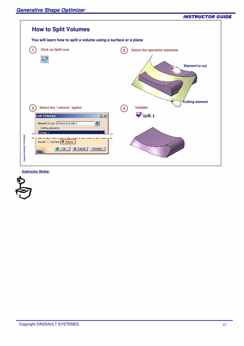
How to Split Volumes
Click on Split icon1 Select the operation elements2
Validate4
Cutting element
Element to cut
Select the “volume” option3
You will learn how to split a volume using a surface or a plane
Instructor Notes:
Generative Shape Optimizer
Copyright DASSAULT SYSTEMES 68
��������������
Cop
yrig
ht D
AS
SA
ULT
SY
STE
ME
S
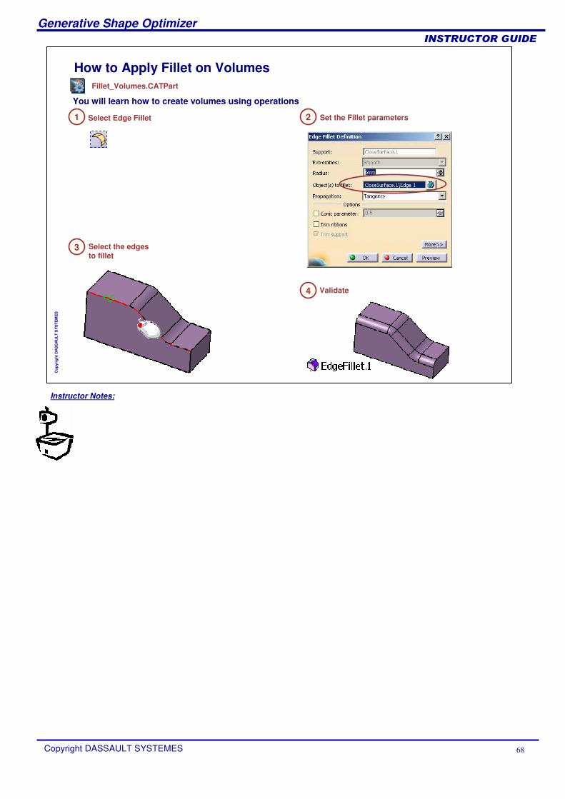
How to Apply Fillet on Volumes
Select Edge Fillet
You will learn how to create volumes using operations
1 Set the Fillet parameters2
Select the edges to fillet
3
Validate4
Fillet_Volumes.CATPart
Instructor Notes:
Generative Shape Optimizer
Copyright DASSAULT SYSTEMES 69
��������������
Cop
yrig
ht D
AS
SA
ULT
SY
STE
ME
S
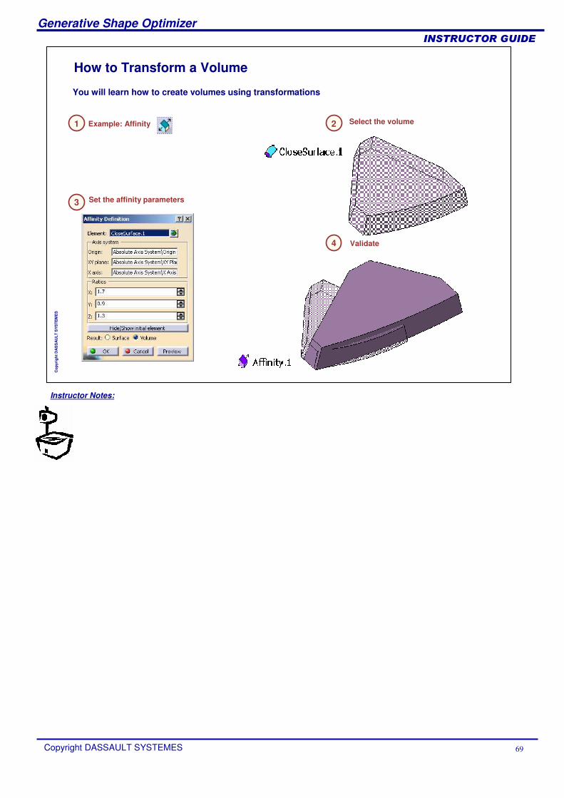
How to Transform a Volume
Example: Affinity
You will learn how to create volumes using transformations
1
Set the affinity parameters3
2
Validate4
Select the volume
Instructor Notes:
Generative Shape Optimizer
Copyright DASSAULT SYSTEMES 70
��������������
Cop
yrig
ht D
AS
SA
ULT
SY
STE
ME
S
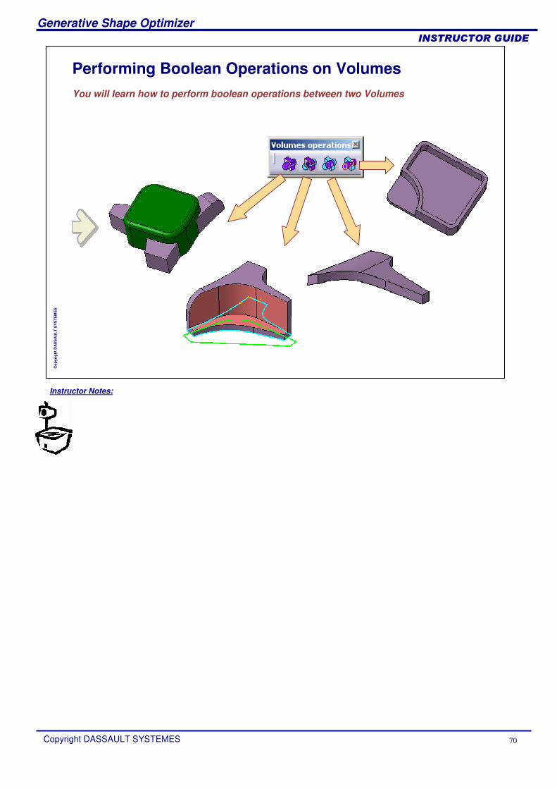
Performing Boolean Operations on VolumesYou will learn how to perform boolean operations between two Volumes
Instructor Notes:
Generative Shape Optimizer
Copyright DASSAULT SYSTEMES 71
��������������
Cop
yrig
ht D
AS
SA
ULT
SY
STE
ME
S
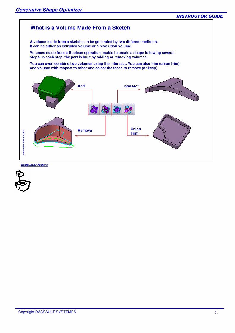
What is a Volume Made From a Sketch
A volume made from a sketch can be generated by two different methods.It can be either an extruded volume or a revolution volume.
Volumes made from a Boolean operation enable to create a shape following several steps. In each step, the part is built by adding or removing volumes.
You can even combine two volumes using the Intersect. You can also trim (union trim) one volume with respect to other and select the faces to remove (or keep)
Remove
Add Intersect
Union Trim

Instructor Notes:
Generative Shape Optimizer
Copyright DASSAULT SYSTEMES 72
��������������
Cop
yrig
ht D
AS
SA
ULT
SY
STE
ME
S
How to Add Volumes
Adding a volume to another volume is uniting the two volumes.
1
Click OK to get the result volume3
Select the two volumes2
Instructor Notes:
Generative Shape Optimizer
Copyright DASSAULT SYSTEMES 73
��������������
Cop
yrig
ht D
AS
SA
ULT
SY
STE
ME
S
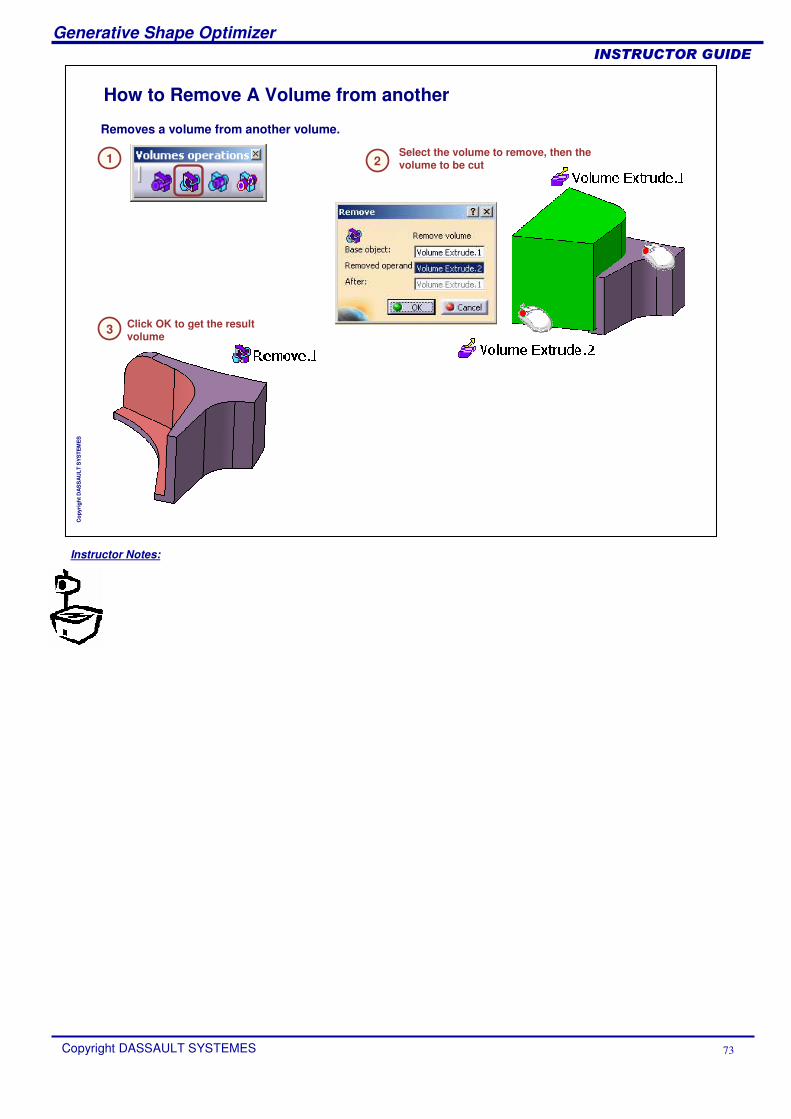
How to Remove A Volume from another
Select the volume to remove, then the volume to be cut
Removes a volume from another volume.
1 2
Click OK to get the result volume3
Instructor Notes:
Generative Shape Optimizer
Copyright DASSAULT SYSTEMES 74
��������������
Cop
yrig
ht D
AS
SA
ULT
SY
STE
ME
S
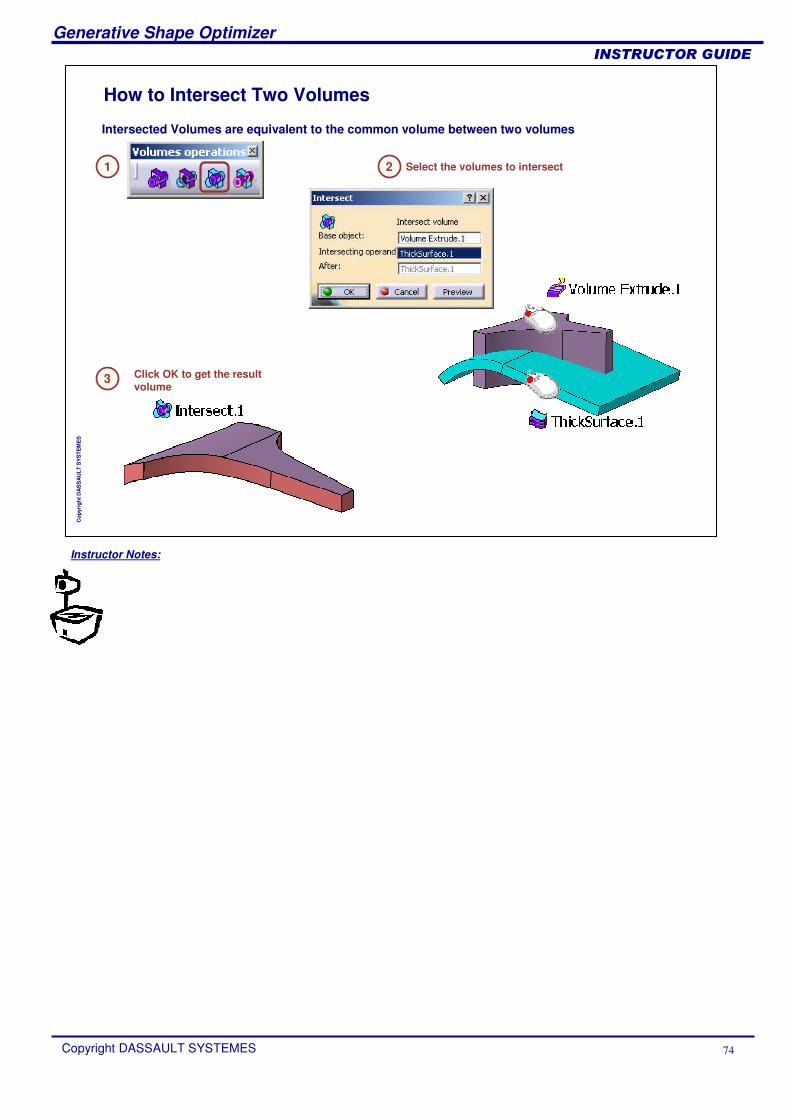
How to Intersect Two Volumes
Intersected Volumes are equivalent to the common volume between two volumes
1
Click OK to get the result volume
3
Select the volumes to intersect2
Instructor Notes:
Generative Shape Optimizer
Copyright DASSAULT SYSTEMES 75
��������������
Cop
yrig
ht D
AS
SA
ULT
SY
STE
ME
S
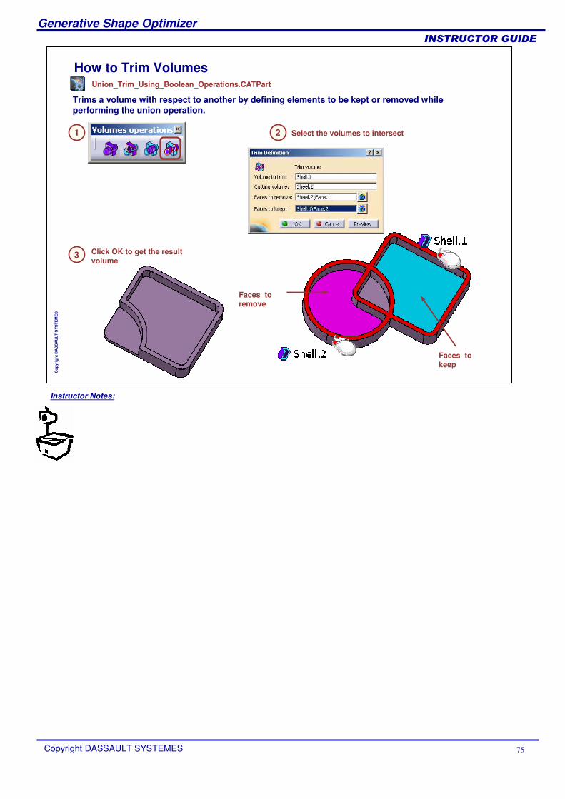
How to Trim Volumes
Trims a volume with respect to another by defining elements to be kept or removed while performing the union operation.
1
Click OK to get the result volume
3
Select the volumes to intersect2
Faces to keep
Faces to remove
Union_Trim_Using_Boolean_Operations.CATPart
Instructor Notes:
Generative Shape Optimizer
Copyright DASSAULT SYSTEMES 76
��������������
Cop
yrig
ht D
AS
SA
ULT
SY
STE
ME
S
To Sum Up
The volume creation tools
The different ways to create volumes
How to combine several volumes using Boolean operations
How to modify existing volumes using operations or transformations
In this section, you have been introduced to volumes.You have seen:
Instructor Notes:
Generative Shape Optimizer
Copyright DASSAULT SYSTEMES 77
��������������
Cop
yrig
ht D
AS
SA
ULT
SY
STE
ME
S
Generative Shape Design Optimizer ExercisesThis lesson provides you with a collection of exercises to practice.
Door Junction ExerciseHolding Arm - Volumes Exercise 1Torch – Volumes Exercise 2Steering Wheel Exercise
Instructor Notes:
Generative Shape Optimizer
Copyright DASSAULT SYSTEMES 78
��������������
Cop
yrig
ht D
AS
SA
ULT
SY
STE
ME
S
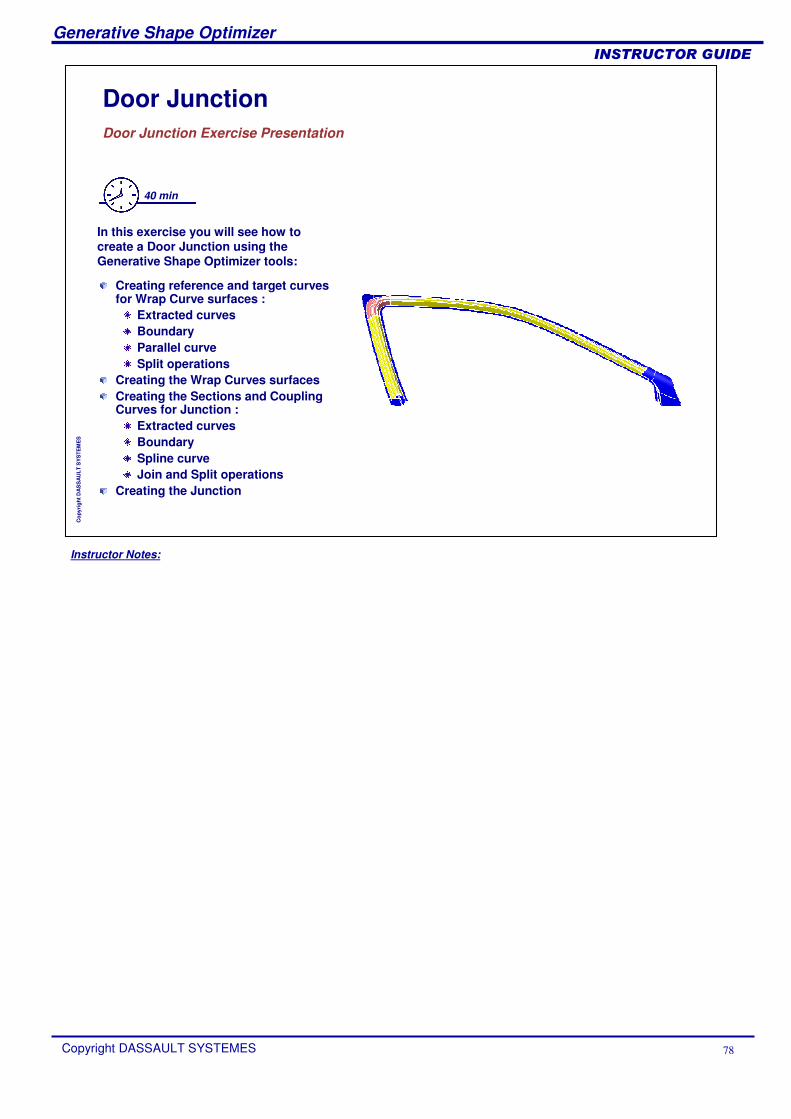
Door JunctionDoor Junction Exercise Presentation
40 min
In this exercise you will see how to create a Door Junction using the Generative Shape Optimizer tools:
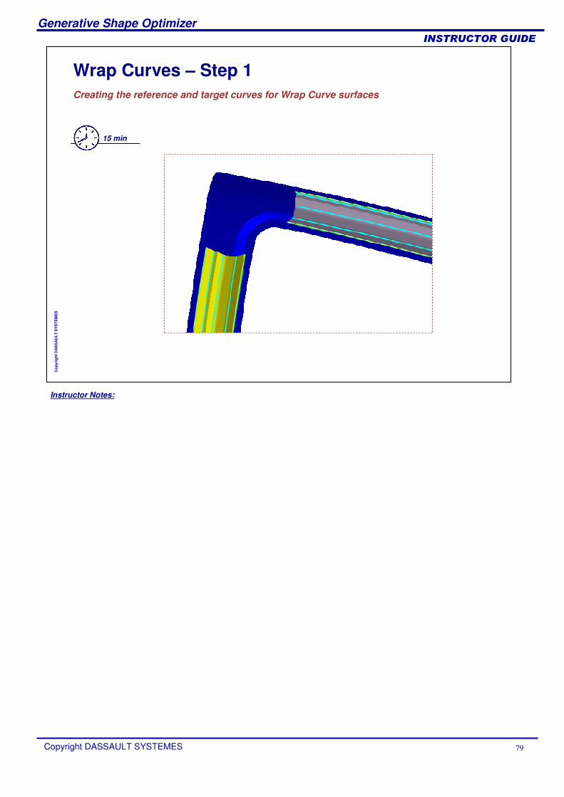
Creating reference and target curves for Wrap Curve surfaces :
Extracted curvesBoundaryParallel curveSplit operations
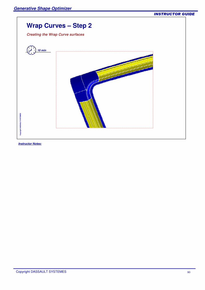
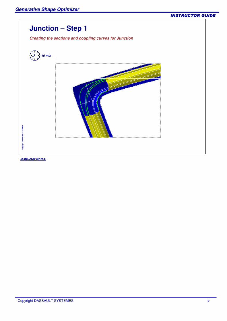
Creating the Wrap Curves surfacesCreating the Sections and Coupling Curves for Junction :
Extracted curvesBoundarySpline curveJoin and Split operations
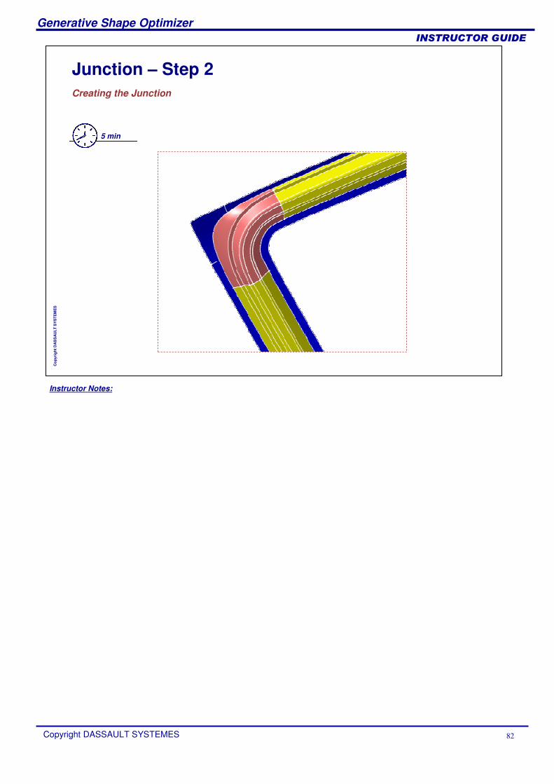
Creating the Junction
Instructor Notes:
Generative Shape Optimizer
Copyright DASSAULT SYSTEMES 79
��������������
Cop
yrig
ht D
AS
SA
ULT
SY
STE
ME
S
Wrap Curves – Step 1Creating the reference and target curves for Wrap Curve surfaces
15 min
Instructor Notes:
Generative Shape Optimizer
Copyright DASSAULT SYSTEMES 80
��������������
Cop
yrig
ht D
AS
SA
ULT
SY
STE
ME
S
Wrap Curves – Step 2Creating the Wrap Curve surfaces
10 min
Instructor Notes:
Generative Shape Optimizer
Copyright DASSAULT SYSTEMES 81
��������������
Cop
yrig
ht D
AS
SA
ULT
SY
STE
ME
S
Junction – Step 1Creating the sections and coupling curves for Junction
10 min
Instructor Notes:
Generative Shape Optimizer
Copyright DASSAULT SYSTEMES 82
��������������
Cop
yrig
ht D
AS
SA
ULT
SY
STE
ME
S
Junction – Step 2Creating the Junction
5 min
Instructor Notes:
Generative Shape Optimizer
Copyright DASSAULT SYSTEMES 83
��������������
Cop
yrig
ht D
AS
SA
ULT
SY
STE
ME
S
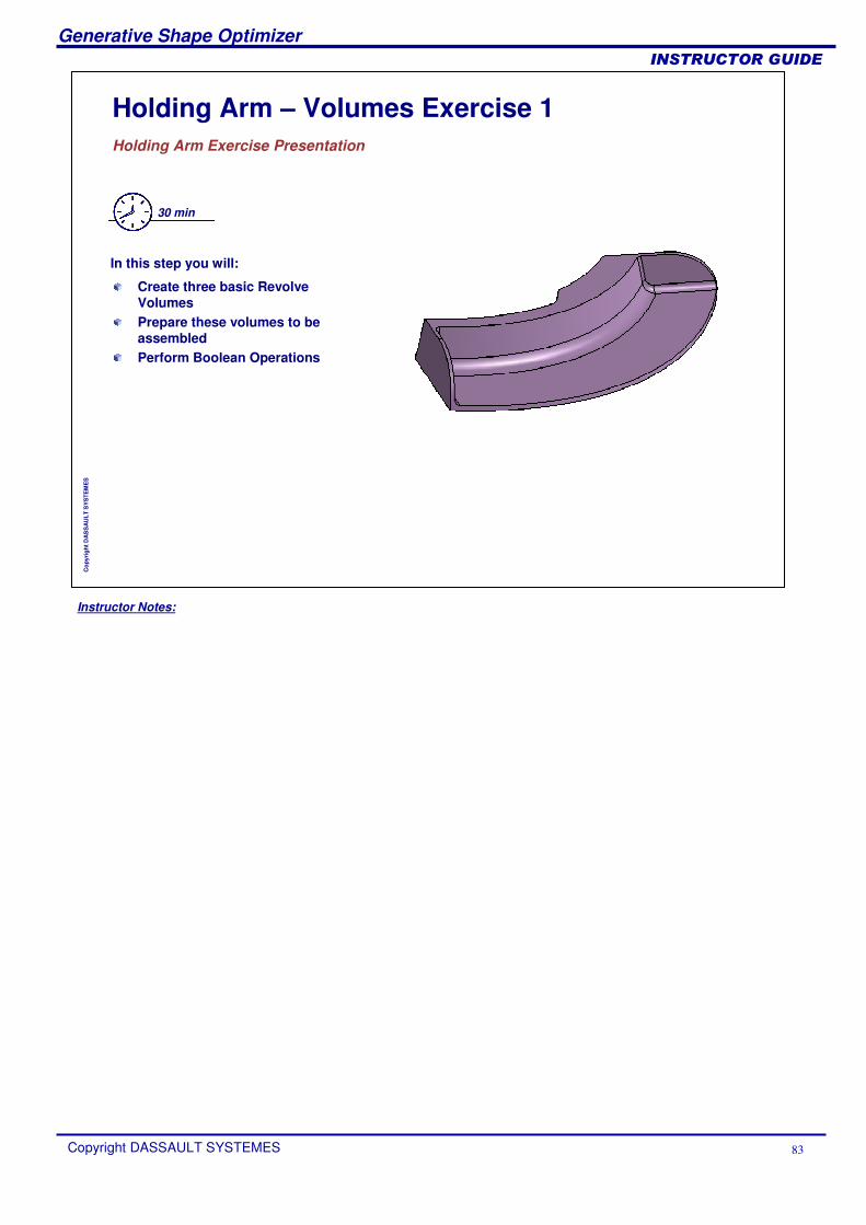
Holding Arm – Volumes Exercise 1Holding Arm Exercise Presentation
30 min
Create three basic Revolve VolumesPrepare these volumes to be assembledPerform Boolean Operations
In this step you will:
Instructor Notes:
Generative Shape Optimizer
Copyright DASSAULT SYSTEMES 84
��������������
Cop
yrig
ht D
AS
SA
ULT
SY
STE
ME
S
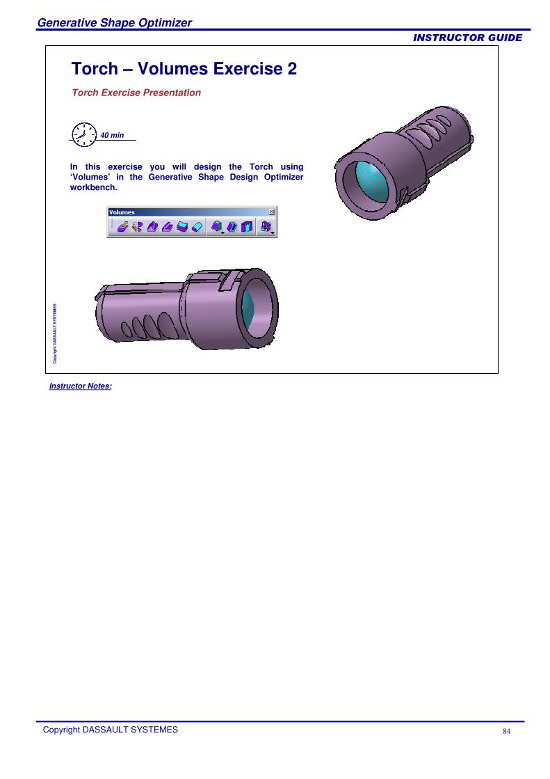
Torch – Volumes Exercise 2Torch Exercise Presentation
40 min
In this exercise you will design the Torch using ‘Volumes’ in the Generative Shape Design Optimizer workbench.
Instructor Notes:
Generative Shape Optimizer
Copyright DASSAULT SYSTEMES 85
��������������
Cop
yrig
ht D
AS
SA
ULT
SY
STE
ME
S
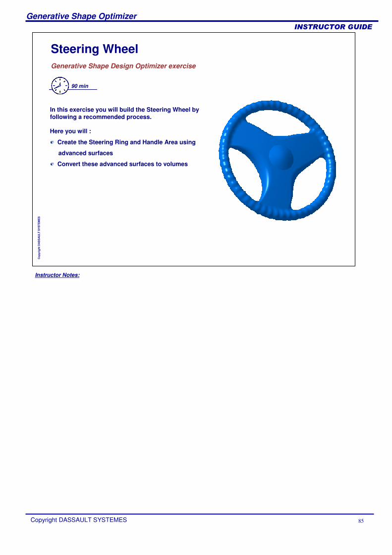
Steering WheelGenerative Shape Design Optimizer exercise
90 min
In this exercise you will build the Steering Wheel by following a recommended process.
Here you will :
Create the Steering Ring and Handle Area using
advanced surfaces
Convert these advanced surfaces to volumes
Instructor Notes:
Generative Shape Optimizer
Copyright DASSAULT SYSTEMES 86
��������������
Cop
yrig
ht D
AS
SA
ULT
SY
STE
ME
S
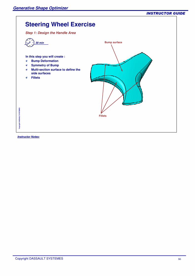
Steering Wheel ExerciseStep 1: Design the Handle Area
30 min
In this step you will create :Bump DeformationSymmetry of BumpMulti-section surface to define the side surfacesFillets
Fillets
Bump surface
Instructor Notes:
Generative Shape Optimizer
Copyright DASSAULT SYSTEMES 87
��������������
Cop
yrig
ht D
AS
SA
ULT
SY
STE
ME
S
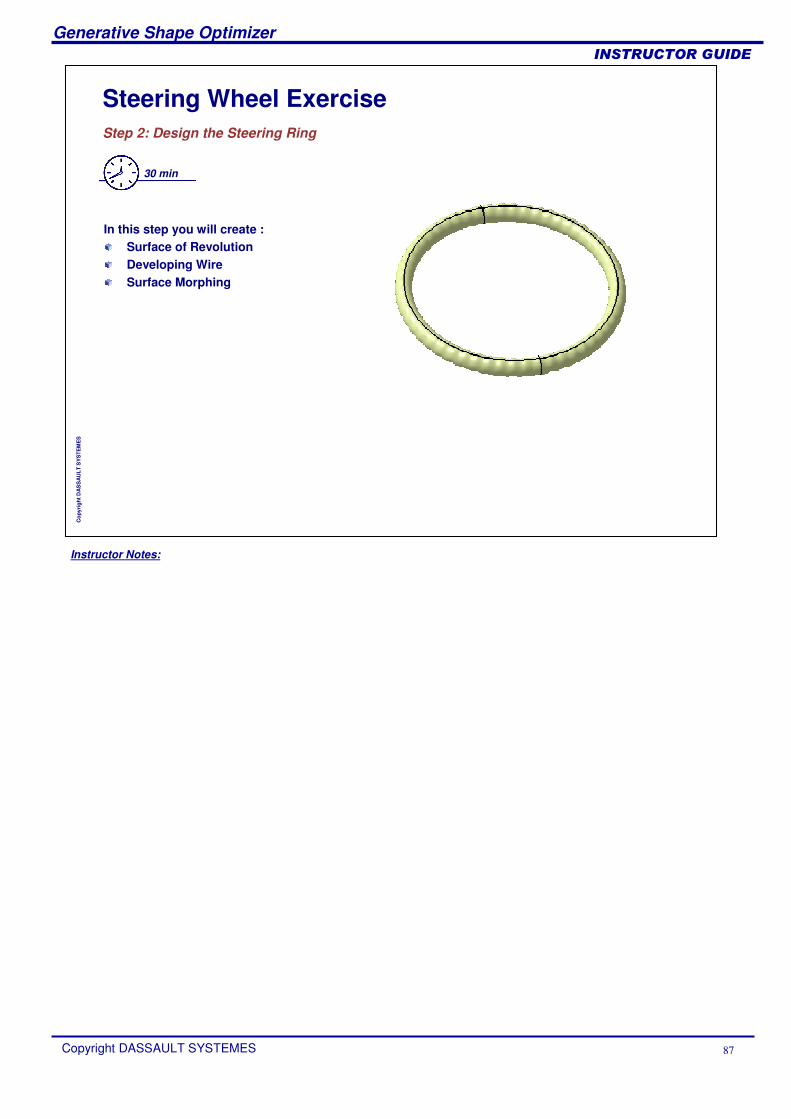
Steering Wheel ExerciseStep 2: Design the Steering Ring
30 min
In this step you will create :Surface of RevolutionDeveloping WireSurface Morphing
Instructor Notes:
Generative Shape Optimizer
Copyright DASSAULT SYSTEMES 88
��������������
Cop
yrig
ht D
AS
SA
ULT
SY
STE
ME
S
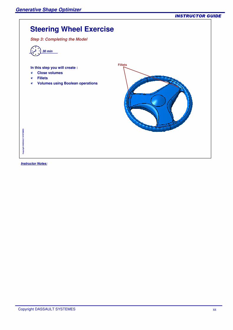
Steering Wheel ExerciseStep 3: Completing the Model
30 min
In this step you will create :Close volumesFilletsVolumes using Boolean operations
Fillets

Instructor Notes:
Generative Shape Optimizer
Copyright DASSAULT SYSTEMES 89
��������������
Cop
yrig
ht D
AS
SA
ULT
SY
STE
ME
S
To Sum Up
In this course you have learnt:
How to create offsets, develop shapes
How to use BIW tools
How to create advanced surfaces like Bumped surface
How to create Volumes