Embed Size (px)
Citation preview
Volume 9العدد
2017Januaryيناير
International Science and
Technology Journal
لعلوم والتقنيةالدولية لمجلة ال
حقوق الطبع محفوظة 2017والتقنية مللعلوالدولية مجلةلل
Copyright © ISTJ 2017 1
Genetic-based neuro-fuzzy Design of PID Controller
for Boost Flyback Converter
Associate Prof. Dr. Sattar Jaber
Al-Isawi
Tareg Abubaker Abulifa
The college of Industrial Technology - Misrata - LIBYA
[email protected] [email protected]
Abstract: The aim of this paper is to design an efficient compensator for the
boost-flyback converter system operates in a continuous
conduction mode. The small signal of the boost-flyback is derived
first to find transfer functions which they help in the study of the
system stability. Genetic algorithm is used to search in the
parameter space for the most suitable controllers’ parameters to
minimize the damping of oscillation modes, to coordinate between
system different controllers. . In order to do this, on-line
measurements of local system signals at converter are chosen as
input signals to an adaptive neuro-fuzzy inference system
(ANFIS). The outputs of each neuro-fuzzy controller are the
desired parameters of system damping controllers. The simulation
of the system is done using the MATLAB programming language.
:الملخص
تعاني اغلب مبدالت القدرة وخاصة المقطعات المستمرة والتي تغير من التيار المستمر النتهاء كل دورة وما يليها من دورة تالية االنتقاليةإلى التيار المستمر من مشكلة الفترة
الهدف من قرار قبل البدء في شوط جديد، لذلك فان حيث تحتاج المبدالت إلى فترة استيعمل على تسريع أداء دالة االنتقال (PIDهذه الورقة هو تصميم دائرة متحكم نوع )
Volume 9العدد
2017Januaryيناير
International Science and
Technology Journal
لعلوم والتقنيةالدولية لمجلة ال
حقوق الطبع محفوظة 2017والتقنية مللعلوالدولية مجلةلل
Copyright © ISTJ 2017 2
رة لكي تبدأ عمل في دورة جديدة، والختيار ثوابت مناسبة لدائرة المتحكم تم استخدام ئللدا (Simulink)ذها عبر البرنامج التشبيهي رزميات الوراثية، وتم تنفيالخو لالدوال العشوائية
لثوابت دائرة المتحكم القيم المناسبة إلىالماتالب، حيث تم التوصل برنامج من خالل وسرعة في األداء لبداية شوط جديد. استقرار جيد هتعطيو المبدل التي تساعد منظومة
Index Terms: converters, control, PID, MATLAB algorithm,
Genetic algorithm, neuro-fuzzy.
I. INTRODUCTION
The dc-dc converters are widely used in industrial applications and
computer hardware circuits. The converters include the buck
converter, the boost converter, the buck-boost converter and
flyback converter. However, because of the effects of parasitic
elements, the output voltage and power transfer efficiency of all
these converters are restricted. The dc to dc converters usually
regulate the output voltage. Most dc to dc converters are designed
to move power in only one direction, from the input to the output.
However, all switching regulator topologies can be made bi-
directional by replacing all diodes with independently controlled
active rectification [1,2].
There are many control strategies for controlling the D.C voltage
regulators, and these control strategies cause large distortion in the
voltage and current waveforms, which causes the appearance of
harmonics in the system and the percentage of these harmonics
depends on the degree of variation of the controlling voltage , and
is widely used as a benchmark for testing control algorithms (PID
controllers, neural networks, fuzzy control, genetic algorithms,
etc.)[3].
The GA searches for an optimum solution over the controllers’
parameter space over wide spectrum of operating conditions. But
Volume 9العدد
2017Januaryيناير
International Science and
Technology Journal
لعلوم والتقنيةالدولية لمجلة ال
حقوق الطبع محفوظة 2017والتقنية مللعلوالدولية مجلةلل
Copyright © ISTJ 2017 3
this approach does not insure good damping at each individual
operating point. The coordinated design problem of flyback
converter based controllers over a wide range of loading
conditions and system configurations are formulated as an
optimization problem with an eigenvalue-based objective function.
The real-coded genetic algorithm is employed to search for
optimal controller parameters [4].
In this paper, the design problem is transformed into an
optimization problem, where the continuous-parameter genetic
algorithm is employed to search for the optimal settings of all
system damping controllers for each individual operating point.
Then, the controllers’ parameters in the system are tuned according
to each operating point by an individual hybrid neuro-fuzzy
controller.
II. BOOST- Flyback Converter
Two different versions of the flyback converter are possible; the
boost-flyback converter and buck-boost flyback converter. The
inductor of the buck-boost converter has been replaced by a
flyback transformer. In this converter a high frequency transformer
is required to provide electrical isolation. The flyback converter is
very common for low power applications. Fig.1 shows the input dc
source Vin and switch (MOSFET) are connected in series with the
coupled inductor on the primary winding. The diode D1 and the
RC output circuit are connected in series with the secondary of the
flyback transformer. The coupling coefficient is assumed to be 1.
Assuming the primary to secondary turns ratio is 1 : n, we get:
𝑣𝐿 = Vin DTs – (V0/𝑛)(1 − D)Ts = 0 (1)
→ (Vo/Vin) = n[D/(1 − D)] (2)
Volume 9العدد
2017Januaryيناير
International Science and
Technology Journal
لعلوم والتقنيةالدولية لمجلة ال
حقوق الطبع محفوظة 2017والتقنية مللعلوالدولية مجلةلل
Copyright © ISTJ 2017 4
→ (Io/Iin)) = n[D/(1 − D)] (3)
Where D represents the steady – state duty ratio. The value of the
inductor that determines the boundary between the CCM and
discontinuous conduction mode (DCM)[5]. The analysis presented
here assumes that the inductor current never goes to zero (called
CCM).Therefore, it is very common to design flyback converters
so that the inductor current does go to zero within each switching
cycle. This operation, known as (DCM), leads to simplification of
control design for flyback converters.
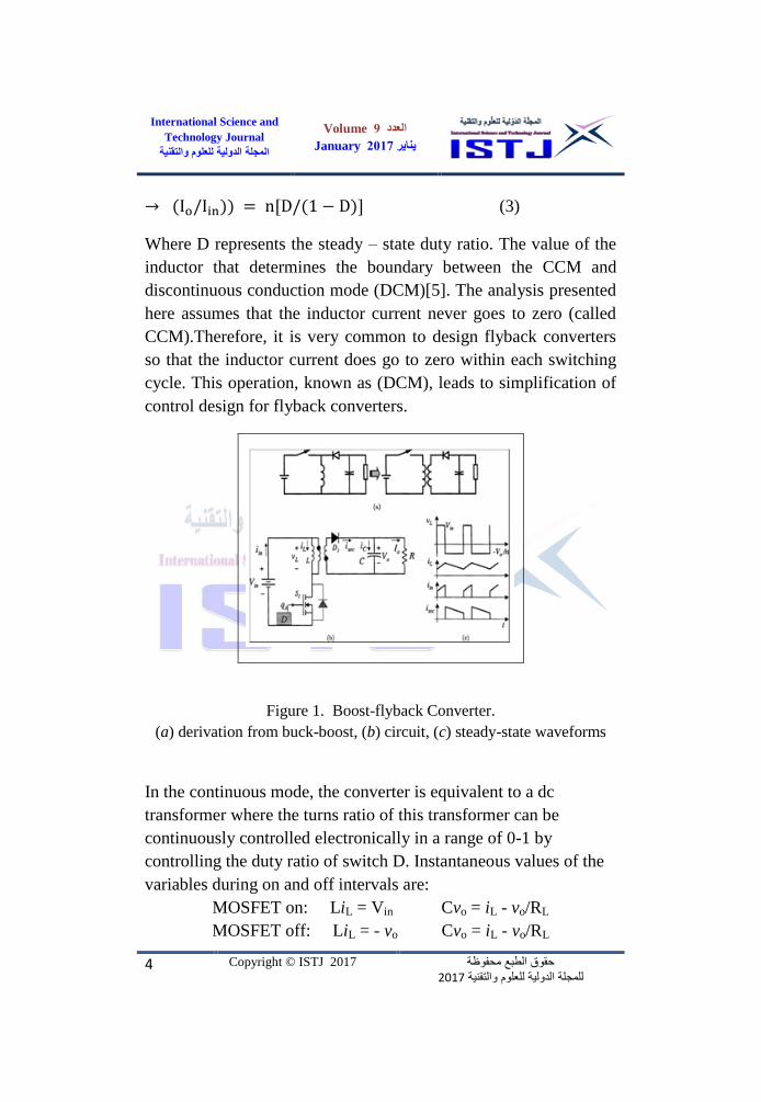
Figure 1. Boost-flyback Converter.
(a) derivation from buck-boost, (b) circuit, (c) steady-state waveforms
In the continuous mode, the converter is equivalent to a dc
transformer where the turns ratio of this transformer can be
continuously controlled electronically in a range of 0-1 by
controlling the duty ratio of switch D. Instantaneous values of the
variables during on and off intervals are:
MOSFET on: LiL = Vin Cvo = iL - vo/RL
MOSFET off: LiL = - vo Cvo = iL - vo/RL
Volume 9العدد
2017Januaryيناير
International Science and
Technology Journal
لعلوم والتقنيةالدولية لمجلة ال
حقوق الطبع محفوظة 2017والتقنية مللعلوالدولية مجلةلل
Copyright © ISTJ 2017 5
In isolated dc-dc converters, multiple outputs are possible with
additional secondary windings of transformers. Only one output is
regulated with a feedback loop, but other outputs depend on the
duty ratio of the regulated one and on their loads.
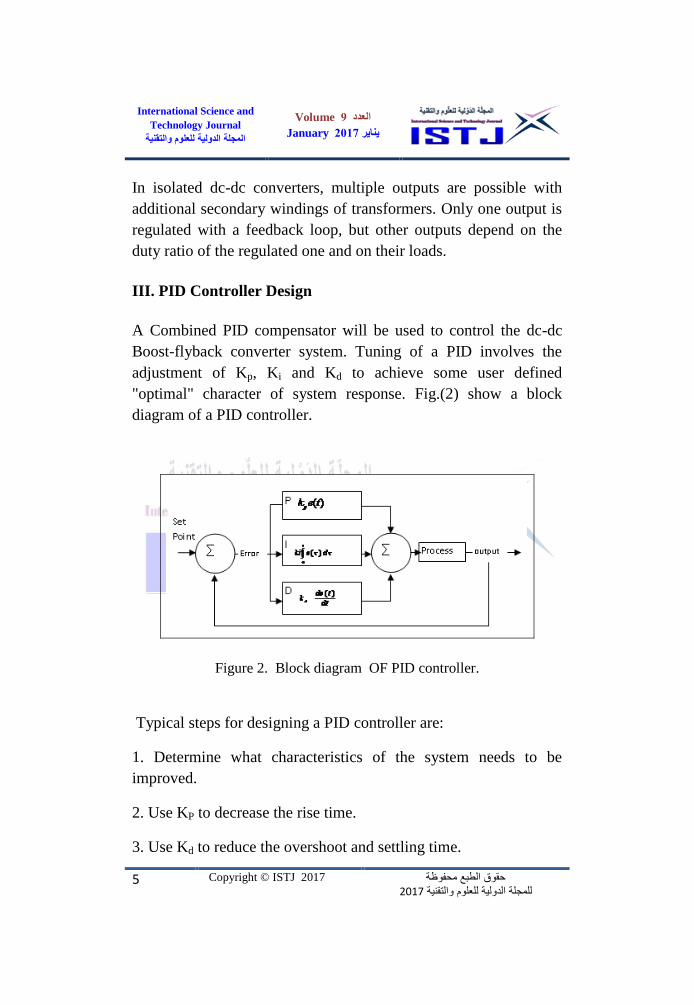
III. PID Controller Design
A Combined PID compensator will be used to control the dc-dc
Boost-flyback converter system. Tuning of a PID involves the
adjustment of Kp, Ki and Kd to achieve some user defined
"optimal" character of system response. Fig.(2) show a block
diagram of a PID controller.
Figure 2. Block diagram OF PID controller.
Typical steps for designing a PID controller are:
1. Determine what characteristics of the system needs to be
improved.
2. Use KP to decrease the rise time.
3. Use Kd to reduce the overshoot and settling time.
Volume 9العدد
2017Januaryيناير
International Science and
Technology Journal
لعلوم والتقنيةالدولية لمجلة ال
حقوق الطبع محفوظة 2017والتقنية مللعلوالدولية مجلةلل
Copyright © ISTJ 2017 6
4. Use Ki to eliminate the steady-state error.
The PID controller encapsulates three of the most important
controller structures in a single package [6]. The parallel form of a
PID controller has transfer function:
)4()1
1()( sTsT
KsC d
i
p
Where:
Kp = Proportional Gain
Ki = Integral Gain.
Kd =Derivative gain
Ti = Reset Time =Kp/Ki.
Td = Rate time or derivative time.
A proportional integral derivative (PID) compensator of the system
has transmittance of the form[1]:
)5(
)1(
)1(*)1(
)(
p
L
zcmc
w
s
s
w
w
s
GsG
)6(
)2.182
1(
)28.6
1(*)626.21
1(
*8.2)(
k
ss
k
k
s
sGc
Volume 9العدد
2017Januaryيناير
International Science and
Technology Journal
لعلوم والتقنيةالدولية لمجلة ال
حقوق الطبع محفوظة 2017والتقنية مللعلوالدولية مجلةلل
Copyright © ISTJ 2017 7
IV. Transfer Functions of Converter
The formula of output voltage variation that represents the effect
of the feedback control on the system is as follows[1]:
where,
)7()(*)(*)(
)(M
vc
V
sdGsGsHsT
the loop gain of the system is:
)8()(*)(*)1
(*)()( sHsdGV
sGsT vM
c
or
)9(
)()*
(1
)1(*)(*)(
)(2
ooo
z
M
doc
w
s
wQ
s
w
s
V
GsHsGsT
The uncompensated loop gain Tu(s), with unity compensator gain
Gc(s) =1, is:
)10(
)()*
(1
)1(*)(
)(2
ooo
z
M
do
u
w
s
wQ
s
w
s
V
GsHsT
Volume 9العدد
2017Januaryيناير
International Science and
Technology Journal
لعلوم والتقنيةالدولية لمجلة ال
حقوق الطبع محفوظة 2017والتقنية مللعلوالدولية مجلةلل
Copyright © ISTJ 2017 8
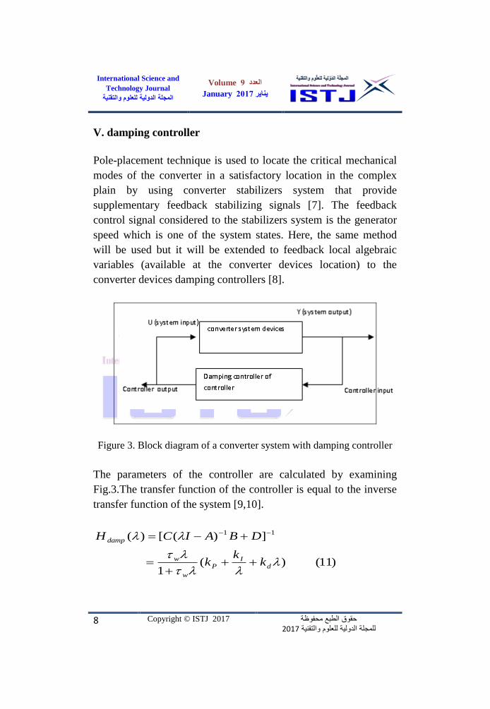
V. damping controller
Pole-placement technique is used to locate the critical mechanical
modes of the converter in a satisfactory location in the complex
plain by using converter stabilizers system that provide
supplementary feedback stabilizing signals [7]. The feedback
control signal considered to the stabilizers system is the generator
speed which is one of the system states. Here, the same method
will be used but it will be extended to feedback local algebraic
variables (available at the converter devices location) to the
converter devices damping controllers [8].
Figure 3. Block diagram of a converter system with damping controller
The parameters of the controller are calculated by examining
Fig.3.The transfer function of the controller is equal to the inverse
transfer function of the system [9,10].
)11()(1
])([)( 11
dI
P
w
w
damp
kk
k
DBAICH

Volume 9العدد
2017Januaryيناير
International Science and
Technology Journal
لعلوم والتقنيةالدولية لمجلة ال
حقوق الطبع محفوظة 2017والتقنية مللعلوالدولية مجلةلل
Copyright © ISTJ 2017 9
The gains kP , kI and kd of the damping controller can be
determined by substituting a pair of the pre-scribed mechanical
mode eigenvalues 1,2 into equation 10, so we have a pair of
algebraic equations with unknown kp, kI and kD [11].
There are many criterion in the literature used to determine the
location and the feedback signal for the damping controllers. The
residue index is used by [11] for the same purpose. The residue
index together with the participation matrix are used to determine
the best location and feedback signal to the damping controller.
A. Adaptive Neuro-Fuzzy Inference Systems (ANFIS)
Define Jang and Sun [10] introduced the adaptive Neuro-Fuzzy
inference system. This system makes use of a hybrid learning rule
to optimize the fuzzy system parameters of a first order Sugeno
system. The ANFIS architecture consists of two training parameter
set:
1. The antecedent membership function parameters.
2. The polynomial parameters [p, q, r].
In [8,9], The ANFIS training paradigm uses gradient descent
algorithm to optimize the antecedent parameters and a least square
algorithm to solve for the consequent parameters. Because it uses
two very different algorithms to reduce the error, the training rule
is called hybrid. The consequent parameters are updated first using
a least squares algorithm and the antecedent parameters are then
updated by back propagating the errors that still exist
B. Genetic algorithm
The Genetic algorithms are derivative-free stochastic optimization
method based on the concepts of natural selection and evolutionary
processes. There were first investigated by John Holland in
1975[11,12]. Their popularity can be attributed to their freedom
Volume 9العدد
2017Januaryيناير
International Science and
Technology Journal
لعلوم والتقنيةالدولية لمجلة ال
حقوق الطبع محفوظة 2017والتقنية مللعلوالدولية مجلةلل
Copyright © ISTJ 2017 10
from dependence on functional derivatives and to their
incorporation to these characteristics:
1- Optimizes with continuous and discrete parameters
2- Deals with a large number of parameters
3- They can jump out of local minimum
4- Simultaneously searches from a wide sampling of the fitness
surface.
Genetic algorithm is used to tune the parameters of the PID
controller previously designed by the pole-placement technique.
The fitness function of the genetic controller is to maximize
damping ratio of the poorly damped modes[13,14].
(12) )( function Fitness1
n
i
iMax
Where n is the number of system modes that have a damping ratio
less than 0.2 .With constraints:
1- Damping ratio for all modes is not less than 0.2.
2- The searching space of kp and kI is between 5.
VI. Results
In this study a design of the feedback controller (PID controller)
for the boost- flyback converter is done to get the best
performance. A MATLAB/Simulink model is build to simulate
and verify the performance of the compensator design. The results
are found that when we design compensator for crossover
frequency equal to 20kHz (10% of the switching frequency), the
phase margin will be equal to 23 degree. Also, by putting the cross
over frequency equal to 30KHz (15% of the switching frequency)
the phase margin will be equal to 14 degree. The small value of the
phase margin ( in T(s)) cases the close loop transfer functions
(1/(1+T)) and (T/(1+T)) to exhibit resonant poles with high Q. The
system transient response exhibit overshoot and ringing. As the
Volume 9العدد
2017Januaryيناير
International Science and
Technology Journal
لعلوم والتقنيةالدولية لمجلة ال
حقوق الطبع محفوظة 2017والتقنية مللعلوالدولية مجلةلل
Copyright © ISTJ 2017 11
phase margin is reduce these characteristics become worst (higher
Q, longer ringing) until the system becomes unstable.
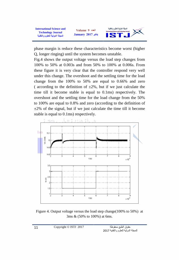
Fig.4 shows the output voltage versus the load step changes from
100% to 50% at 0.003s and from 50% to 100% at 0.006s. From
these figure it is very clear that the controller respond very well
under this change. The overshoot and the settling time for the load
change from the 100% to 50% are equal to 0.66% and zero
( according to the definition of ±2%, but if we just calculate the
time till it become stable is equal to 0.1ms) respectively. The
overshoot and the settling time for the load change from the 50%
to 100% are equal to 0.8% and zero (according to the definition of
±2% of the signal, but if we just calculate the time till it become
stable is equal to 0.1ms) respectively.
Figure 4. Output voltage versus the load step change(100% to 50%) at
3ms & (50% to 100%) at 6ms.
Volume 9العدد
2017Januaryيناير
International Science and
Technology Journal
لعلوم والتقنيةالدولية لمجلة ال
حقوق الطبع محفوظة 2017والتقنية مللعلوالدولية مجلةلل
Copyright © ISTJ 2017 12
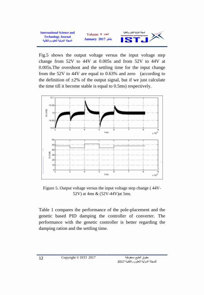
Fig.5 shows the output voltage versus the input voltage step
change from 52V to 44V at 0.005s and from 52V to 44V at
0.005s.The overshoot and the settling time for the input change
from the 52V to 44V are equal to 0.63% and zero (according to
the definition of ±2% of the output signal, but if we just calculate
the time till it become stable is equal to 0.5ms) respectively.
Figure 5. Output voltage versus the input voltage step change ( 44V-
52V) at 4ms & (52V-44V)at 5ms.
Table 1 compares the performance of the pole-placement and the
genetic based PID damping the controller of converter. The
performance with the genetic controller is better regarding the
damping ration and the settling time.
Volume 9العدد
2017Januaryيناير
International Science and
Technology Journal
لعلوم والتقنيةالدولية لمجلة ال
حقوق الطبع محفوظة 2017والتقنية مللعلوالدولية مجلةلل
Copyright © ISTJ 2017 13
Table 1. Compares of pole-placement and genetic based PID damping
controller of converter
Controller
Damping
Ratio Frequency
Over
shoot Time
Pole-place. -1.7 12.1i 0.1395 2.0136 81 % 2.5 sec.
GA -.8311.10i 0.1422 2.1001 80 % 2.5 sec.
Pole-place. -2.3 12.5i 0.1395 2.1226 79 % 2.5 sec.
GA -.2513.40i 0.1791 2.3211 81 % 2.5 sec.
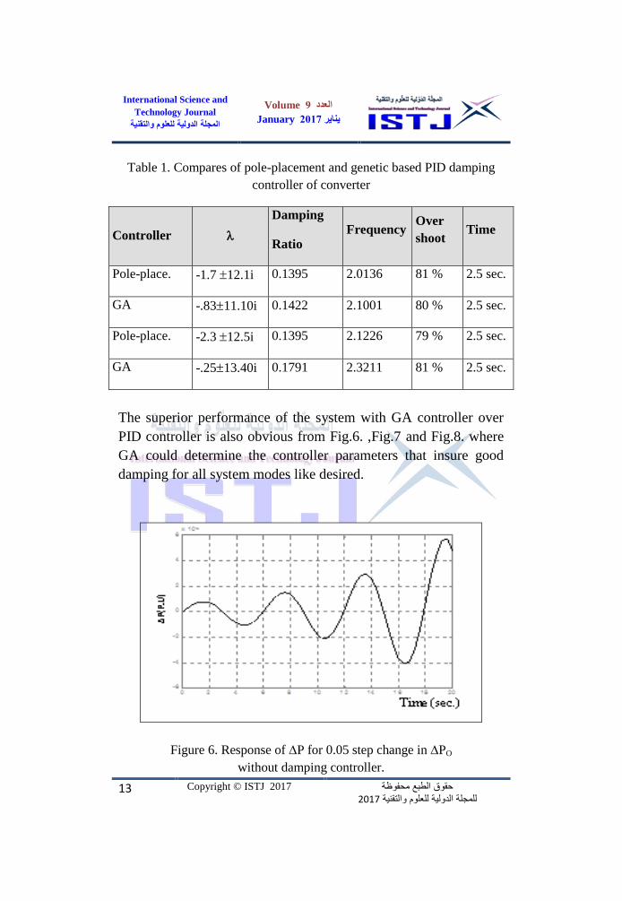
The superior performance of the system with GA controller over
PID controller is also obvious from Fig.6. ,Fig.7 and Fig.8. where
GA could determine the controller parameters that insure good
damping for all system modes like desired.
Figure 6. Response of P for 0.05 step change in PO
without damping controller.
Volume 9العدد
2017Januaryيناير
International Science and
Technology Journal
لعلوم والتقنيةالدولية لمجلة ال
حقوق الطبع محفوظة 2017والتقنية مللعلوالدولية مجلةلل
Copyright © ISTJ 2017 14
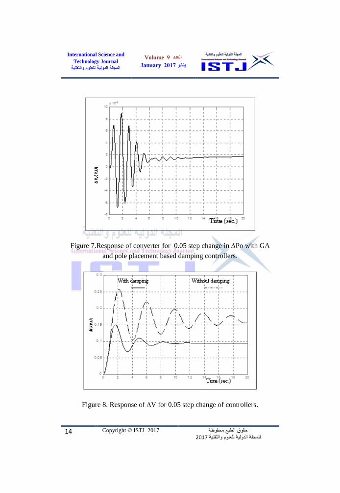
Figure 7.Response of converter for 0.05 step change in Po with GA
and pole placement based damping controllers.
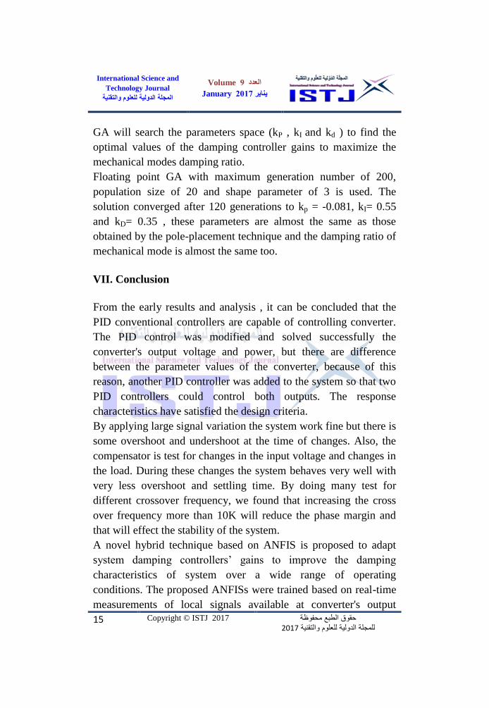
Figure 8. Response of V for 0.05 step change of controllers.
Volume 9العدد
2017Januaryيناير
International Science and
Technology Journal
لعلوم والتقنيةالدولية لمجلة ال
حقوق الطبع محفوظة 2017والتقنية مللعلوالدولية مجلةلل
Copyright © ISTJ 2017 15
GA will search the parameters space (kP , kI and kd ) to find the
optimal values of the damping controller gains to maximize the
mechanical modes damping ratio.
Floating point GA with maximum generation number of 200,
population size of 20 and shape parameter of 3 is used. The
solution converged after 120 generations to kp = -0.081, kI= 0.55
and kD= 0.35 , these parameters are almost the same as those
obtained by the pole-placement technique and the damping ratio of
mechanical mode is almost the same too.
VII. Conclusion
From the early results and analysis , it can be concluded that the
PID conventional controllers are capable of controlling converter.
The PID control was modified and solved successfully the
converter's output voltage and power, but there are difference
between the parameter values of the converter, because of this
reason, another PID controller was added to the system so that two
PID controllers could control both outputs. The response
characteristics have satisfied the design criteria.
By applying large signal variation the system work fine but there is
some overshoot and undershoot at the time of changes. Also, the
compensator is test for changes in the input voltage and changes in
the load. During these changes the system behaves very well with
very less overshoot and settling time. By doing many test for
different crossover frequency, we found that increasing the cross
over frequency more than 10K will reduce the phase margin and
that will effect the stability of the system.
A novel hybrid technique based on ANFIS is proposed to adapt
system damping controllers’ gains to improve the damping
characteristics of system over a wide range of operating
conditions. The proposed ANFISs were trained based on real-time
measurements of local signals available at converter's output

Volume 9العدد
2017Januaryيناير
International Science and
Technology Journal
لعلوم والتقنيةالدولية لمجلة ال
حقوق الطبع محفوظة 2017والتقنية مللعلوالدولية مجلةلل
Copyright © ISTJ 2017 16
voltage and power. Damping controllers’ gains can be determined
by the ANFISs, which makes the proposed stabilizer relatively
simple and suitable for practical on-line implementation.
The implementation of PID control method is done by adjusting
the value of gain kP, KI, and KD, in order to get the best impulse
response of the system. From the previous Genetic algorithms
design, it was determined that the controller stabilizes of the
converter.
References
[1] Sattar Jaber Al-Isawi, " Genetic-based neuro-fuzzy Design of
PID Controller for Buck Boost Converter ", 2nd
World
Symposium on Web Applications and Networking
(WSWAN2015), Sousse - Tunis, March 21-23, 2015.
[2] Sattar Jaber Al-Isawi, Ehsan A. Abd Al-Nabi, "Design of The
Feedback Controller (PID Controller) for The Buck Boost
Converter", tth
International Conference on Information
Technology(ICIT 2009), Al-Zaytoonah University, Amman,
Jordan, June 3-5, 2009.
[3] Sattar Jaber Al-Isawi , Ehsan A. Abd Al-Nabi "DESIGN A
DISCRETE CONTROL SYSTEM OF PWM AC-AC
CONVERTER", Drive“,Proc. Of Int. UPEC, 2008.
[4] Sattar Jaber Al-Isawi, " Genetic-based neuro-fuzzy Design of
PID Controller for an Inverted Pendulum System ". 1st
International Conference on Electrical and Computer
Eng(ICECE2013), Benghazi-Libya, 26-28/3/2013.
[5] Sattar Jaber Al-Isawi, Abdallah O. Hawal, " PMSG-based Grid
Connected of Wind Power Converter with PID Controller ".
ISBN 9780989130547. ( SDIWC 2014).
[6] Sattar Jaber Al-Isawi, " Genetic-based neuro-fuzzy Design of
FACTS Controller in Power System", International Conference
Volume 9العدد
2017Januaryيناير
International Science and
Technology Journal
لعلوم والتقنيةالدولية لمجلة ال
حقوق الطبع محفوظة 2017والتقنية مللعلوالدولية مجلةلل
Copyright © ISTJ 2017 17
on Cloud Computer Information Systems(ICRE2014),
Hammamet- Tunis, January 17-19, 2014.
[7] M. A. Abido and Y. L. Abdel-Magid, “A Hybrid Neuro-Fuzzy
Power System Stabilizer for Multi-Machine Power systems”,
IEEE Transaction on Power Systems, Vol. 13, No. 4, pp. 1323-
1330, Nov. 1998.
[8] K. Ellithy and A. Al-Naamany, “A Hybrid Neuro-Fuzzy Static
VAR Compensator Stabilizer for Power System Damping
Improvement in the Presence of Load Parameters Uncertainty”,
Journal of Electrical Power Systems Research, (56), pp. 211-
223, 2000.
[9] Jyh-Shing R. Jang, Chuen-Tsai Sun, Eiji Mizutani,
Neuro_Fuzzy and Soft Computing, Prentice-Hall, 1997.
[10] M. Reformat, E. Kuffel, D. Woodford and W. Pedrycz,
“Application of Genetic Algorithm for Control Design in
Power systems”, IEE Proc., Gener. Transm. Distrib., Vol. 145,
No. 4, pp. 345-354, July 1998.
[11] Goldberg, D. E. "Genetic Algorithms in Search, Optimization
and Machine Learning,Reissue".Addison-Wesley Publishing
Company, 1989.
[12] Michalewicz, Z. "Genetic Algorithms + Data Structures =
Evolution Programs",3rd Ed.,Springer-Verlag, Berlin. 1996.
Koza, J. R., Keane, M. A., Yu, J., Bennett III, F. H.,
Mydlowec, W. "Automatic Creation of Human-Competitive
Programs and Controllers by Means of Genetic Programming,
Genetic Programming and Evolvable Machines" ,Vol. 1,
pp121-164,2000.