Embed Size (px)
Citation preview
Geotechnical Challenges in Hydropower Development in China
Third Lumb LectureOctober 6 2004
Hong Kong
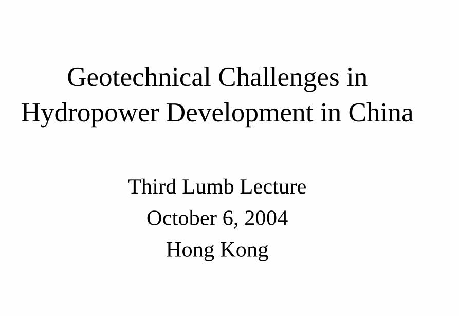
中國地形圖
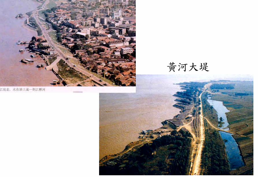
長江中游之荊江大堤
黃河大堤
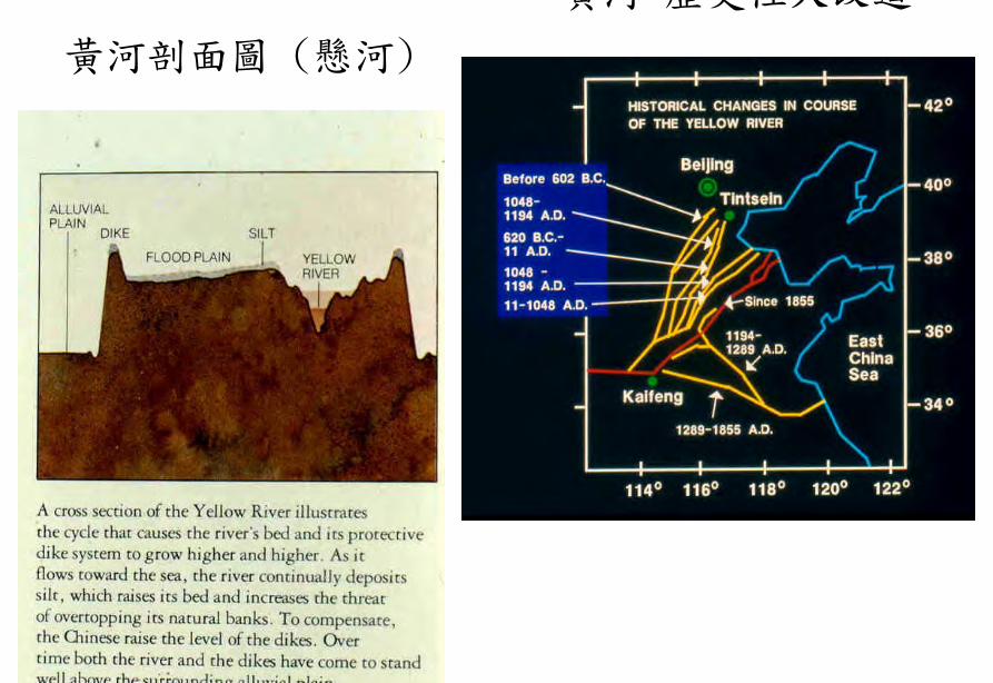
黃河剖面圖 (懸河)
黃河 歷史性大改道
1935年長江決堤於荊州
長江 大洪澇過後
水患
先民治水圖
都江堰圖
廣西靈渠
修黃河堤 (1938年)
修堤(材料運送)
修堤(Compaction)
1931 荊江大堤
現代大堤
Earth Dam
Concrete Dam
三門峽 河南
三門峽大壩
遼寧省心窩水庫
心窩水庫大壩裂縫
青海 泃后 土石壩潰壩
Overtopping of dam
Geotechnical Issues (A) Earth and Rockfill Dams
- Piping due to seepage - Overtopping
Geotechnical Issues
(B) Dam Foundations
- Foundation failure due to seepage and erosion(eg St Francis Dam Teton Dam)
- Foundation failure due to wedge slide (egMalpasset Dam)
- Foundation failure due to fault movement (egBaldwin Hill Dam)
- Foundation movement due to basal sliding(hydrostatic pressure + seismic load + ice loadrArr FS lt 1)
St Francis Dam 1928
St Francis Dam 1928 - after failure
Quail Creek Dyke 1988
Malpasset Dam 1959
Foundation Treatment
Stewart Falls
seepage in inspection tunnel
Stewartville after asphalt grouting
Ge Zhou Ba in Operation
Ge Zhou Ba Foundation Treatment
Geotechnical Issues (C) Seismic Hazards
- Natural earthquakes - Reservoir-induced seismicity - Fault movement
San Fernando Dam LA 1971
San Fernando Dam failure
San Fernando cross-section
唐山陟河水庫 1976
Baldwin Hill Dams Los Angeles 1963
水庫地震
新豐江水電站
新豐江
新豐江
Geotechnical Issues (D) Reservoir Slopes
- Natural terrain landslides (eg Xintan) - Landslides due to reservoir impounding (eg
Vaiont Manwan Huanglungtan Zigui) - Landslide dams (eg Dadu River Usoi
Yigong)
Vaiont Dam
Vaiont Dam
Vaiont Dam
Vaiont Dam
Vaiont Dam
Vaiont Dam
Vaiont Dam
新灘滑坡
新灘滑坡
三峽秭歸千將坪滑坡
三峽巴東滑坡
鏈子崖加固工程
TGP Layout
TGP Layout
TGP Shiplock
TGP Shi l k
TGP Shiplock Section
TGP Shiplock Section
TGP Rock Core
TGP Rock Core
Man Wan Dam
Man Wan Landslide Site
The landslide of the Manwan Hydropower ProjectJanuary 8 1989
云南小湾水电站左岸坝前边坡
开挖时面貌
湖南五強溪水庫滑坡
Da Lake
Xiao Lake
Yinping dam
Rockfallsource
Da Lake
四川大渡河滑坡壩(1933年大地震)
MUDFLOW OF THE LONGYANGXIA POWER STATION
Time of occurrenceAugust 4 of 1997 at 2355
Cause of the incidentA 2-hour constant rainfall with a total precipitation of 55 mm
Source of the mudflow material Natural deposit and construction waste in the Beidagou Gully
龙羊峡水电站128万千瓦
Geotechnical Issues (E) Tunnels and Excavations in Rock
- Fracture-induced instability (rock mass
classification and tunnel support design) - Stress-induced instability - Time-dependent deformation (eg Niagara vs
Three Gorges shiplocks)
Hoover Dam
Hoover Dam
廣州抽水蓄能電站
Two Types of Instability Underground
bull Stress ndash controlledbull Fracture - controlled
Rock Mass Classifications
bull Rock Quality Designation (RQD)
bull Rock Mass Rating System (RMR)
bull Rock Tunnelling Quality Index (Q)
Class Qualitative description BQ Value
I Hard rock intact gt 550
II Hard rock relatively intactRelatively hard rock intact
550 ~ 451
III Hard rock relatively fracturedRelatively hard or interlayered of hard and weak rock relatively
intactRelatively weak rock intact
450 ~ 351
IV Hard rock fracturedRelatively hard rock fractured-relatively fracturedRelatively weak rock or interlayered of weak and hard rock with dominant
weak rock relatively intact or relatively fracturedWeak rock intact or relatively intact
350 ~ 251
V Relatively weak rock fracturedWeak rock fractured-relatively fracturedExtremely weak rock extremely fractured
lt 250
National Standard for Engineering Classification of Rock Masses (GB 50218-94)
Table 1 Basic quality (BQ) of rock mass
BQ = 90 + 3 Rc + 250 Kv
where Rc = uniaxial compressive strength (MPa)Kv = intactness index of rock mass
Table 2 Classification based on uniaxial compressive strength Rc
Rc (MPa) gt 60 60 ~ 30 30 ~ 15 15 ~ 5 lt 5
Description Hard rock Relatively hard rock
Relatively weak rock
Weak rock Extremely weak rock
Table 4 Intactness Factor Kv as a function of Joint Index Jv
Jv (number of joints
m3)
lt 3 3 ~ 10 10 ~ 20 20 ~ 35 gt 35
Kv gt 075 075 ~ 055 055 ~ 035 035 ~ 015 lt 015
Kv =
Vpm= in-situ velocity of longitudinal elastic wave (kms)
Vpr = velocity of longitudinal elastic wave in intact rock (kms)
2
pt
pm
VV
⎟⎟⎠
⎞⎜⎜⎝
⎛
For engineering classification use [BQ] amended for groundwater joint orientation and in-situ stress conditions
[BQ] = BQ ndash 100 (K1 + K2 + K3)
where BQ = basic quality
K1 = correction factor for groundwater
K2 = correction factor for orientation of planes of weakness
K3 = correction factor for in-situ stress conditions
Table 5 K1 values - Correction factor for groundwater conditions
gt450 450 ~ 351 350 ~251 lt250
Wet or drops 0 01 02 ~ 03 04 ~ 06
Shower or flowP lt 01 MPa
Q lt 10 L min m
01 02 ~ 03 04 ~ 06 07 ~ 09
Shower or flowP lt01 MPa
Q lt 10 L min m
02 10
BQK1
Groundwaterinflow
Table 6 K2 values - Correction factor for orientation of planes of weakness
Relation of structure plane to tunnel axis
α lt 30 o= 30 o ~ 75 o
α gt 30 oβ gt 75 o
Other combinations
K2 04 ~ 06 0 ~ 02 02 ~ 04
α - angle between strike of structure plane and tunnel axisβ - dipping angle of structure plane
Table 7 K3 values - Correction factor for in-situ stress conditions
gt 550 550 ~ 351 450 ~ 351 350 ~251 lt 250
Extremely high stress
10 10 10 ~ 15 10 ~ 15 10
High stress 05 05 05 05 ~ 10 05 ~ 10
BQK3
Initialstress state
Technical Specifications for Water Resources and Hydropower ProjectsRock Mass Rating for Tunnelling Projects
Rock class
Rock stability Host rock
rating
StrengthStress S Support type
I Stable long termstability generally no unstable block
100 ~ 85 gt 4 No support or locally bolting or thin shotcreting in case of large span systematic shotcrete bolt and meshII Basically stable no
plasticity deformation85 ~ 65 gt 4
if S lt 4go to III
III Poor stability locally plasticity deformation or collapse
65 ~ 45 gt 2if S lt 2go to IV
Systematic shotcrete bolt and mesh if span = 20 ~ 25 m concrete lining is needed
IV Unstable short self-standing time large scale collapse
45 ~ 25 gt 2if S lt 2go to V
Systematic shotcrete bolt and mesh and concrete lining
V Extremely unstable severe collapse
lt 25 No limits
Host rock rating (HRR) = A + B + C + D + E(somewhat similar to Bieniawskirsquos RMR)
Rating on rock strength (A)
Type of rock materialHard rock Weak rock
Hard rock Moderately hard rock
Relatively weak rock
Weak rock
Uniaxial strength of saturated rock (MPa)
100 ~ 60 60 ~ 30 30 ~ 15 15 ~ 5
Rating (A)Hard rock 30 ~ 20 20 ~ 10
Weak rock 10 ~ 5 5 ~ 0
For uniaxial strength σc gt 100 MPa rock mass rating is 30
Rating on rock intactness (B)
Intactness Intact Relatively intact
Poor intactness
Relatively fractured
Fractured
Intactness factor Kv 10 ~ 075 075 ~ 055 055 ~ 035 035 ~ 015 lt 015
Hard rock 40 ~ 30 30 ~ 22 22 ~ 14 14 ~ 6 lt 6
Weak rock 25 ~ 19 19 ~ 14 14 ~ 9 9 ~ 4 lt 4
Rating (B)
Rating on state of structure planes (C)
Aperture (mm) Filling Roughness evenness Hard rock Relatively weak rock Weak rock
Closed lt 05Undulating rough 27 27 18
Planar smooth 21 21 14
Slight open 05 ~ 50
No filling Undulating rough 24 24 17Undulating smooth or
planar rough21 21 14
Planar smooth 15 15 8
Slacks
Undulating rough 21 21 14
Undulating smooth or planar rough
17 17 11
Planar smooth 12 12 8
Mud
Undulating rough 15 15 10
Undulating smooth or planar rough
12 12 8
Open gt 50
Planar smooth 9 9 6
Slacks 12 12 8Mud 6 6 4
For a length of structure plane which is less than 3 m in hard rock and relatively weak rock rating would increase by 3 for weak rock rating would increase by 2 For length gt 10 m decrease rating by 3 and 2 respectively for hard rock and relatively weak rock If aperture gt 10 m without filling rating is 0
Rating on groundwater condition (D)
Basic rating(A + B + C)
State Wet Drops Linear Flow Flow
Quantity of flow
(Lminm)
lt 25or
lt 10
25-125or
10-100
gt 125or
gt 100
Water head(m)
100-85
Rating on Groundwater Conditions
(D)
0 0 -2 ~ -6
85-65 0 ~ -2 0 ~ -2 -6 ~ -10
65-45 -2 ~ -6 -2 ~ -6 -10 ~ -14
45 ~ 25 -6 ~ -10 -10 ~ -14 -14 ~ -18
lt 25 -10 ~ -14 -14 ~ -18 -18 ~ -20
Rating on orientation of structure planes (E)
Angle betweenstrike of
structure planeand tunnel axis
( o )
90o ~ 60o 60o ~ 30o lt 30o
Dipping angle( o )
gt70 75~45 45~20 lt20 gt70 75~45 45~20 45~20
Crown -2
Wall -5
-5
-2
-12-10-10
0 -2 -5
-5
-10
lt20 gt70 70~45 lt20
0 -2 -12
0
-12-10
-12 0
-5
-2 -5 -10
Rating (E)
Factor Basis for Rating Rating
Saturated Compressive Strength (MPa) gt100 100-60 60-30 30-15 15-5
Rating for A gt30 30-20 20-10 10-5 5-0
Intactness Coefficient 10-075 075-055 055-035 035-015 lt015
σc gt 30 MPa 40-30 30-22 22-14 14-5 lt6
σc lt 30 MPa
Degree of openness
Infillings
Polishness of surface
σc gt 60 MPa
σc 60 - 30 MPa 27-21 24-15 21-12 15-9 12-6
18-14 17-8 14-8 10-6 8-4
gt10m
-3
-2
100-85
σc lt 30 MPa
70o- 45o 45o- 20o lt20o
-5 -10
0-2
-2
-5
σc gt 60 MPa
σc lt 60 MPa
Seeping dripping 0
Linear flow 0 rarr -2
-2 rarr -6
90o - 60o
gt70o
Roof 0
Sidewall -2
Gush of water
25-19 19-14 14-9 9-4 lt4
Closed lt05mm
Slightly open 05 ndash 50 mm Open gt 5 mm
Nil Rock fragments
Clay Fragmented Clay
Flat polished to curved rough
27-21 24-15 21-12 15-9 12-6
Length of structural surface lt3 m 3-10 m
+3 0
+2 0
A + B + C1 + C2 Rating 85-65 64-45 45-25 lt25
0 rarr -2 -2 rarr -6 -6 rarr -10 -10 rarr -14
-2 rarr -6 -6 rarr -10 -10 rarr -14 -14 rarr -18
-6 rarr -10 -10 rarr -14 -14 rarr -18 -18 rarr -20
Angle between tunnel alignment and structural orientation (strike)
60o - 30o lt 30o
Dip of structural orientation gt 70o 70o - 4 5o 45o - 20o lt 20o gt 70o 70o - 45o 45o - 20o lt 20o
2 -5 -10 -12 -5 -10 -12 -12
-5 -10 -2 0 -10 -12 -5 0
Rating for E
E
Rating for D
D
Rating for C2
C2
Rating for C1
Structural surface condition
C1
Rating for B
B
A
Host Rock Rating (HRR)
Recommended rock parameters
Class Gravity density γ(kNm3)
Friction angle ϕ (o)
Cohesion C(MPa)
Deformation module E(MPa)
Poisson ratio ν
I gt 60 gt 21 gt 33 lt 02
II 60 ~ 50 21 ~ 15 33 ~ 20 02 ~ 025
III 265 ~ 245 50 ~ 39 15 ~ 07 20 ~ 6 025 ~ 03
IV 245 ~ 225 39 ~ 27 07 ~ 02 6 ~ 13 03 ~ 035
V lt 225 lt 27 lt 02 lt 13 gt 035
gt 265
Recommended rock strength parameters
ClassConcrete-rock contact Rock mass Deformation
modulus
fprime cprime (MPa) fprime cprime (MPa) E0 X 104 (MPa)
I 15 ~ 13 15 ~ 13 16 ~ 14 25 ~ 20 gt 20
II 13 ~ 11 13 ~ 11 14 ~ 12 20 ~ 15 20 ~ 10
III 11 ~ 09 11 ~ 07 12 ~ 08 15 ~ 07 10 ~ 05
IV 09 ~ 07 07 ~ 03 08 ~ 055 07 ~ 03 05 ~ 02
V 07 ~ 04 03 ~ 005 055 ~ 040 03 ~ 005 02 ~ 002
fprime cprime - Shear strength
Design Applications of HRR
Rock PropertiesRock Type
Rock Mass Stability Host Rock
Rating (HRR)
Strength vs Stress Ratio (S) f C (MPa) E(x 104MPa)
Support Requirements
I Stable with long-term stability no unstable blocks in general
100 - 85 16 - 14 25 - 20 gt 20 Unsupported or localized boltsshotcrete or thin shotcrete add wire mesh for tunnels with large span
II Essentially stable with overall stability no plastic deformation localized rockfall
85 - 65 Downgrade to III for S lt 4
14 - 12 20 - 15 20 - 10
III Poor stability localized plastic deformation cave-in if unsupported temporarily stable in intact relatively soft rock
65 - 45 Downgrade to IV for S lt 2
12 - 08 15 - 07 10 - 05 Bolts and shotcrete with wire mesh concrete lining for tunnel span of 20 -25 m
IV Unstable very short standup time relatively large deformationfailure may occur
45 - 25 Downgrade to V for S lt 1
08 - 055 07 - 03 05 - 02 Bolts and shotcrete with re-bar mesh and concrete lining
V Very unstable could not stand up severe deformationfailure
lt 25 055 - 040 03 - 005 02 - 002
SUPPORT PARAMETERS(National Standard for Design of Bolt-shotcrete Support)
Span (m)Rock Class
B lt 5 m 5 lt B lt 10 10 lt B lt 20 15 lt B lt 20 20 lt B lt 25 m
I No support Shotcrete50 mm
(1) Shotcrete 80-100 mm(2) Shotcrete 50 mmbolt 20-25 m
Shotcrete Shotcrete 120-150 mmwith mesh bolt 30-40 m
II Shotcrete50 mm
(1) Shotcrete 80-100 mm(2) Shotcrete 50 mmbolt 15-2m
(1) Shotcrete 120-150 mm mesh if necessary(2) Shotcrete 80-120 mmbolt 2-3 m mesh if necessary
Shotcrete 120-150 mmmesh bolt 25-30 m
Shotcrete 150-200 mmmesh bolt 3-4 m
III (1) Shotcrete 80-100 mm(2) Shotcrete 50 mmbolt 15-2 m
(1) Shotcrete 120-150 mm mesh if necessary(2) Shotcrete 80-120 mmbolt 2-3 m mesh if necessary
Shotcrete 100-150 mmmesh bolt 20-30 m
Shotcrete 150-200 mmmesh bolt 3-4 m
IV Shotcrete 80-100 mmbolt 15-20 m
Shotcrete 100-200 mmmesh bolt 20-25 m bottom arch if necessary
Shotcrete 150-200 mmmesh bolt 25-30 m bottom arch if necessary
V Shotcrete 120-150 mmmesh bolt 15-20 m bottom arch if necessary
Shotcrete 150-200 mmmesh bolt 20-30 m bottom frame if necessary
GB-J86-85 (Revised)
Comparison of Rock Mass Classification Systems
System Range of Classes
Main Factors
Q 001-1000
9 RQD Jn (joint set number) Jr (joint roughness number) Ja (joint alteration number) Stress reduction factor SRF
RMR 0-100 5 Rock strength RQD Spacing conditions and orientation of joints Groundwater
HRR 0-100 5 Rock strength Intactness Conditions and Orientation of Weakness Planes Groundwater Initial Stresses
BQ lt 250-gt 500
5 Rock strength Intactness Groundwater Orientation of Weakness Planes Initial Stresses
Important Factors that are common among the various systems
1 Rock strength
2 Intactness
3 Condition of planes of weakness
4 Groundwater
5 Orientation of discontinuities
6 Initial stresses
Support systems for underground excavations in ChinaRock Class Span (m) Shotcrete Steel Mesh Bolt Concrete Lining
Total Number
of Projects
Thickness (cm)
Diameters(mm)
Spacing (m)
Diameter (mm)
Length (m)
Spacing (m)
Thickness(cm)
Number of Works
I 5-10 3-15 no no 18-22 12-30 Random no 9
10-15 3-20 6-12 025-15 18-22 15-35 10-15 no 9
15-20 10-20 no no 20-22 10-30 10-15 no 3
II 5-10 5-15 6-10 02-13 16-20 12-21 10-12 no 2 10
10-15 4-20 6-18 02-13 18-22 15-35 08-15 30-50 13
15-20 8-16 8-12 02-13 16-32 20-40 12-15 no 10
III 5-10 5-20 6-10 02-10 18-22 16-30 10-15 wall 1 12
10-15 5-20 5-12 02-10 16-24 15-35 10-15 11
15-20 10-16 6-12 02-08 16-30 20-40 08-12 8
IV 5-10 15-20 6-14 02-025 18-22 18-40 075-125 40 4 10
10-15 5-20 6-12 02-03 16-22 25-40 08-125 50 2 5
15-20 20 10-19 025 22 20 12 1
V 5-10 10-15 8-14 02-025 16-22 15-36 08-12 40 2
4
7
10-15 18-20 6-12 02-03 20-22 25-35 08-10 60 4
Three Gorges ProjectAmended [BQ] Values for Granite
Maximum [BQ]max = 630
Minimum [BQ]min = 500
Average [BQ]mean = 565
Class I- to II+
Guangzhou Pumped Storage Project
bull Location north of Guangzhou Guangdong Province
bull Underground Powerhouse
1465 m x 22 m x 445 m (L x W x H)
at 330 - 400 m depth completed in 1993
bull Host Rock Biotite granite
bull Support System Bolts (at 2 x 15 m spacing)+ 15 cm shotcrete in both crown and
sidewalls
Xiaolangdi Project
bull Location on Yellow River Henan Provincebull Underground Powerhouse
2515 m x 262 m x 614m (L x W x H)At 70 ndash 100 m depth completed in 1999
bull Host Rock Sandstone with argillaceous bedsbull Support System Bolts (at 15 spacing) with wiremesh
and shotcret (20 cm) in crownBolts (at 15 spacing) in sidewallsAnchors locally where required
Xiaolangdi Project on Yellow RiverProposed support parameters in design stage
Support DesignCavern Type Location Rock Type
Rock Grade Tensile Bolt Re Shotcrete
Top T14 III Φ 25 15 X 15 m (mortar bolt)
L = 53 m (alternatively)Φ 6 20 X 20 cmδ = 10 cm (C20)
Tailrace Cavern
Top T14 III Φ 28 15 X 15 m
L = 84 m (alternatively)Φ 8 20 X 20 cmδ = 20 cm (C20)
Sidewall T14
T13-2
III Φ 25 15 X 15 mL = 128 m (alternatively)
Φ 8 20 X 20 cmδ = 15 cm (C20)
Top T14 II- Φ 25 15 X 15 m
L = 73 m (alternatively)Φ 6 20 X 20 cmδ = 15 cm (C20)
Sidewall T14 II- Φ 25 15 X 15 m
L = 53 m (alternatively)Φ 6 20 X 20 cmδ = 10 cm (C20)
Sidewall T14 III Φ 25 15 X 15 m (mortar bolt)
L = 4 mΦ 6 25 X 25 cmδ = 10 cm (C20)
Transformer Cavern
Main Power-house
T14 thick to massive siliceous fine-grained sandstone
T13-2 thick to massive argillaceous and calcareous silty fine-grained sandstone
Xiaolangdi Project on Yellow RiverActual support used at construction stage
Support DesignCavern Type Location Rock Type
Rock Grade Tensile Bolt Re Shotcrete
Support Pres
(MPa)0112
0056
0104
0104
056
0044
Top T14 III Φ 32 3 X 3 m L = 5 m P = 150 KN
Φ 32 3 X 3 m L = 3 m P = 150 KNΦ 6 25 X 25 cmδ = 15 cm (C20)
Tailrace Cavern
Top T14 III Φ 32 3 X 3 m L = 8 m P = 150 KN
Φ 32 3 X 3 m L = 6 m P = 150 KNCable L = 25 m 45 X 6 m P = 1500 KN
Φ 8 20 X 20 cmδ = 20 cm (C20)
Sidewall T14
T13-2
III Φ 32 3 X 3 m L = 10 m P = 150 KNΦ 32 3 X 3 m L = 6 m P = 150 KNTwo rows of pre-stressed bolt added for argillized interlayers 500 KN L = 15 m
Φ 8 20 X 20 cmδ = 20 cm (C20)
Top T14 II- Φ 32 24 X 24 m L = 8 m P = 150 KN
Φ 32 24 X 24 m L = 4 m P = 150 KNΦ 6 20 X 20 cmδ = 20 cm (C20)
Sidewall T14 II- Φ 32 24 X 24 m L = 6 m P = 150 KN
Φ 32 24 X 24 m L = 4 m P = 150 KNΦ 6 25 X 25 cmδ = 15 cm (C20)
Sidewall T14 III Φ 32 15 X 15 m
L = 4 m P = 100 KNΦ 6 25 X 25 cmδ = 10 cm (C20)
Transformer Cavern
Main Power-house
Er Tan Dam
Er Tan Dam
Er Tan Dam Layout
Er Tan Dam Layout
Er Tan Under Construction
Er Tan Under Construction
Er Tan Underground Power House
Er Tan Underground Power House
Er Tan Diversion Tunnel
Er Tan Diversion Tunnel
Er Tan Rock Discing
Er Tan Rock Discing
Er Tan Geostress
Er Tan Geostress(kgcm2)
Strain Energy Approach to Modelling Rock Squeeze Problems
For a virtual displacement δ e
Work Done = Force x Displacement = Feδ e = (δ e)TFe
where Fe = corresponding nodal force Strain energy recovered from unit volume of rock = Stress x Strain = σ ε = ε Tσ = ([B] δ e)T ([D]ε ) = (δ e)T[B][D] ε Work Done = Strain Energy Released (δ e)TFe = (δ e)T int vol [B]T[D] ε dv
or Fe = int vol [B]T[D] ε dv
Some Features of Chinese Hydro Projects
bull Same design framework as in the Westbull Very detailed site investigationsbull Including numerous aditsbull Sometimes leads to significant cost savingsbull (eg Ertan dam allowed to be founded on Class III
rock instead of Class II as called for by Design Standard
bull Strong emphasis on geology and rock mass structure studies
bull Very detailed analysis including numerical modelling AI etc
青海龍羊峽
青海 黃河 李家峽 拱壩壩址
青海 李家峽
探洞
滑面
滑面
李家峽水庫 老滑坡體
剖面
電力需求增長
水電資源
Schematic Map of Hydropower Stations of 1GW and above in Operation or Under Construction
Jin Sha River Hydro Power
南水北調三線
Method of Generation Pros Cons
Capital Construction Cost
(Ratio) Fuel Cost
Fossil
bull Short construction period (2-3 years)
bull Easy to start up
bull Air pollution bull Ashsludge
disposal 1 Relatively high
Hydraulic
bull Longer construction period (gt 5 years)
bull Resettlement of affected population
bull Preservation of cultural amp historic relics
2
Nuclear
bull Relatively long construction period (ge 10 years)
bull Nuclear safety concern
bull Nuclear waste disposal needs
5 Relatively low
Other generation methods solar wind biomass etc
The Joy of being a Hydro Project Engineer
bull Free helicopter jet rides(safe most of the time)
bull Exotic places with breathtaking scenerysceneryand colorful folklore(no tourists around no phone calls etc)
攔路酒(四川 涼山)
中國地形圖
長江中游之荊江大堤
黃河大堤
黃河剖面圖 (懸河)
黃河 歷史性大改道
1935年長江決堤於荊州
長江 大洪澇過後
水患
先民治水圖
都江堰圖
廣西靈渠
修黃河堤 (1938年)
修堤(材料運送)
修堤(Compaction)
1931 荊江大堤
現代大堤
Earth Dam
Concrete Dam
三門峽 河南
三門峽大壩
遼寧省心窩水庫
心窩水庫大壩裂縫
青海 泃后 土石壩潰壩
Overtopping of dam
Geotechnical Issues (A) Earth and Rockfill Dams
- Piping due to seepage - Overtopping
Geotechnical Issues
(B) Dam Foundations
- Foundation failure due to seepage and erosion(eg St Francis Dam Teton Dam)
- Foundation failure due to wedge slide (egMalpasset Dam)
- Foundation failure due to fault movement (egBaldwin Hill Dam)
- Foundation movement due to basal sliding(hydrostatic pressure + seismic load + ice loadrArr FS lt 1)
St Francis Dam 1928
St Francis Dam 1928 - after failure
Quail Creek Dyke 1988
Malpasset Dam 1959
Foundation Treatment
Stewart Falls
seepage in inspection tunnel
Stewartville after asphalt grouting
Ge Zhou Ba in Operation
Ge Zhou Ba Foundation Treatment
Geotechnical Issues (C) Seismic Hazards
- Natural earthquakes - Reservoir-induced seismicity - Fault movement
San Fernando Dam LA 1971
San Fernando Dam failure
San Fernando cross-section
唐山陟河水庫 1976
Baldwin Hill Dams Los Angeles 1963
水庫地震
新豐江水電站
新豐江
新豐江
Geotechnical Issues (D) Reservoir Slopes
- Natural terrain landslides (eg Xintan) - Landslides due to reservoir impounding (eg
Vaiont Manwan Huanglungtan Zigui) - Landslide dams (eg Dadu River Usoi
Yigong)
Vaiont Dam
Vaiont Dam
Vaiont Dam
Vaiont Dam
Vaiont Dam
Vaiont Dam
Vaiont Dam
新灘滑坡
新灘滑坡
三峽秭歸千將坪滑坡
三峽巴東滑坡
鏈子崖加固工程
TGP Layout
TGP Layout
TGP Shiplock
TGP Shi l k
TGP Shiplock Section
TGP Shiplock Section
TGP Rock Core
TGP Rock Core
Man Wan Dam
Man Wan Landslide Site
The landslide of the Manwan Hydropower ProjectJanuary 8 1989
云南小湾水电站左岸坝前边坡
开挖时面貌
湖南五強溪水庫滑坡
Da Lake
Xiao Lake
Yinping dam
Rockfallsource
Da Lake
四川大渡河滑坡壩(1933年大地震)
MUDFLOW OF THE LONGYANGXIA POWER STATION
Time of occurrenceAugust 4 of 1997 at 2355
Cause of the incidentA 2-hour constant rainfall with a total precipitation of 55 mm
Source of the mudflow material Natural deposit and construction waste in the Beidagou Gully
龙羊峡水电站128万千瓦
Geotechnical Issues (E) Tunnels and Excavations in Rock
- Fracture-induced instability (rock mass
classification and tunnel support design) - Stress-induced instability - Time-dependent deformation (eg Niagara vs
Three Gorges shiplocks)
Hoover Dam
Hoover Dam
廣州抽水蓄能電站
Two Types of Instability Underground
bull Stress ndash controlledbull Fracture - controlled
Rock Mass Classifications
bull Rock Quality Designation (RQD)
bull Rock Mass Rating System (RMR)
bull Rock Tunnelling Quality Index (Q)
Class Qualitative description BQ Value
I Hard rock intact gt 550
II Hard rock relatively intactRelatively hard rock intact
550 ~ 451
III Hard rock relatively fracturedRelatively hard or interlayered of hard and weak rock relatively
intactRelatively weak rock intact
450 ~ 351
IV Hard rock fracturedRelatively hard rock fractured-relatively fracturedRelatively weak rock or interlayered of weak and hard rock with dominant
weak rock relatively intact or relatively fracturedWeak rock intact or relatively intact
350 ~ 251
V Relatively weak rock fracturedWeak rock fractured-relatively fracturedExtremely weak rock extremely fractured
lt 250
National Standard for Engineering Classification of Rock Masses (GB 50218-94)
Table 1 Basic quality (BQ) of rock mass
BQ = 90 + 3 Rc + 250 Kv
where Rc = uniaxial compressive strength (MPa)Kv = intactness index of rock mass
Table 2 Classification based on uniaxial compressive strength Rc
Rc (MPa) gt 60 60 ~ 30 30 ~ 15 15 ~ 5 lt 5
Description Hard rock Relatively hard rock
Relatively weak rock
Weak rock Extremely weak rock
Table 4 Intactness Factor Kv as a function of Joint Index Jv
Jv (number of joints
m3)
lt 3 3 ~ 10 10 ~ 20 20 ~ 35 gt 35
Kv gt 075 075 ~ 055 055 ~ 035 035 ~ 015 lt 015
Kv =
Vpm= in-situ velocity of longitudinal elastic wave (kms)
Vpr = velocity of longitudinal elastic wave in intact rock (kms)
2
pt
pm
VV
⎟⎟⎠
⎞⎜⎜⎝
⎛
For engineering classification use [BQ] amended for groundwater joint orientation and in-situ stress conditions
[BQ] = BQ ndash 100 (K1 + K2 + K3)
where BQ = basic quality
K1 = correction factor for groundwater
K2 = correction factor for orientation of planes of weakness
K3 = correction factor for in-situ stress conditions
Table 5 K1 values - Correction factor for groundwater conditions
gt450 450 ~ 351 350 ~251 lt250
Wet or drops 0 01 02 ~ 03 04 ~ 06
Shower or flowP lt 01 MPa
Q lt 10 L min m
01 02 ~ 03 04 ~ 06 07 ~ 09
Shower or flowP lt01 MPa
Q lt 10 L min m
02 10
BQK1
Groundwaterinflow
Table 6 K2 values - Correction factor for orientation of planes of weakness
Relation of structure plane to tunnel axis
α lt 30 o= 30 o ~ 75 o
α gt 30 oβ gt 75 o
Other combinations
K2 04 ~ 06 0 ~ 02 02 ~ 04
α - angle between strike of structure plane and tunnel axisβ - dipping angle of structure plane
Table 7 K3 values - Correction factor for in-situ stress conditions
gt 550 550 ~ 351 450 ~ 351 350 ~251 lt 250
Extremely high stress
10 10 10 ~ 15 10 ~ 15 10
High stress 05 05 05 05 ~ 10 05 ~ 10
BQK3
Initialstress state
Technical Specifications for Water Resources and Hydropower ProjectsRock Mass Rating for Tunnelling Projects
Rock class
Rock stability Host rock
rating
StrengthStress S Support type
I Stable long termstability generally no unstable block
100 ~ 85 gt 4 No support or locally bolting or thin shotcreting in case of large span systematic shotcrete bolt and meshII Basically stable no
plasticity deformation85 ~ 65 gt 4
if S lt 4go to III
III Poor stability locally plasticity deformation or collapse
65 ~ 45 gt 2if S lt 2go to IV
Systematic shotcrete bolt and mesh if span = 20 ~ 25 m concrete lining is needed
IV Unstable short self-standing time large scale collapse
45 ~ 25 gt 2if S lt 2go to V
Systematic shotcrete bolt and mesh and concrete lining
V Extremely unstable severe collapse
lt 25 No limits
Host rock rating (HRR) = A + B + C + D + E(somewhat similar to Bieniawskirsquos RMR)
Rating on rock strength (A)
Type of rock materialHard rock Weak rock
Hard rock Moderately hard rock
Relatively weak rock
Weak rock
Uniaxial strength of saturated rock (MPa)
100 ~ 60 60 ~ 30 30 ~ 15 15 ~ 5
Rating (A)Hard rock 30 ~ 20 20 ~ 10
Weak rock 10 ~ 5 5 ~ 0
For uniaxial strength σc gt 100 MPa rock mass rating is 30
Rating on rock intactness (B)
Intactness Intact Relatively intact
Poor intactness
Relatively fractured
Fractured
Intactness factor Kv 10 ~ 075 075 ~ 055 055 ~ 035 035 ~ 015 lt 015
Hard rock 40 ~ 30 30 ~ 22 22 ~ 14 14 ~ 6 lt 6
Weak rock 25 ~ 19 19 ~ 14 14 ~ 9 9 ~ 4 lt 4
Rating (B)
Rating on state of structure planes (C)
Aperture (mm) Filling Roughness evenness Hard rock Relatively weak rock Weak rock
Closed lt 05Undulating rough 27 27 18
Planar smooth 21 21 14
Slight open 05 ~ 50
No filling Undulating rough 24 24 17Undulating smooth or
planar rough21 21 14
Planar smooth 15 15 8
Slacks
Undulating rough 21 21 14
Undulating smooth or planar rough
17 17 11
Planar smooth 12 12 8
Mud
Undulating rough 15 15 10
Undulating smooth or planar rough
12 12 8
Open gt 50
Planar smooth 9 9 6
Slacks 12 12 8Mud 6 6 4
For a length of structure plane which is less than 3 m in hard rock and relatively weak rock rating would increase by 3 for weak rock rating would increase by 2 For length gt 10 m decrease rating by 3 and 2 respectively for hard rock and relatively weak rock If aperture gt 10 m without filling rating is 0
Rating on groundwater condition (D)
Basic rating(A + B + C)
State Wet Drops Linear Flow Flow
Quantity of flow
(Lminm)
lt 25or
lt 10
25-125or
10-100
gt 125or
gt 100
Water head(m)
100-85
Rating on Groundwater Conditions
(D)
0 0 -2 ~ -6
85-65 0 ~ -2 0 ~ -2 -6 ~ -10
65-45 -2 ~ -6 -2 ~ -6 -10 ~ -14
45 ~ 25 -6 ~ -10 -10 ~ -14 -14 ~ -18
lt 25 -10 ~ -14 -14 ~ -18 -18 ~ -20
Rating on orientation of structure planes (E)
Angle betweenstrike of
structure planeand tunnel axis
( o )
90o ~ 60o 60o ~ 30o lt 30o
Dipping angle( o )
gt70 75~45 45~20 lt20 gt70 75~45 45~20 45~20
Crown -2
Wall -5
-5
-2
-12-10-10
0 -2 -5
-5
-10
lt20 gt70 70~45 lt20
0 -2 -12
0
-12-10
-12 0
-5
-2 -5 -10
Rating (E)
Factor Basis for Rating Rating
Saturated Compressive Strength (MPa) gt100 100-60 60-30 30-15 15-5
Rating for A gt30 30-20 20-10 10-5 5-0
Intactness Coefficient 10-075 075-055 055-035 035-015 lt015
σc gt 30 MPa 40-30 30-22 22-14 14-5 lt6
σc lt 30 MPa
Degree of openness
Infillings
Polishness of surface
σc gt 60 MPa
σc 60 - 30 MPa 27-21 24-15 21-12 15-9 12-6
18-14 17-8 14-8 10-6 8-4
gt10m
-3
-2
100-85
σc lt 30 MPa
70o- 45o 45o- 20o lt20o
-5 -10
0-2
-2
-5
σc gt 60 MPa
σc lt 60 MPa
Seeping dripping 0
Linear flow 0 rarr -2
-2 rarr -6
90o - 60o
gt70o
Roof 0
Sidewall -2
Gush of water
25-19 19-14 14-9 9-4 lt4
Closed lt05mm
Slightly open 05 ndash 50 mm Open gt 5 mm
Nil Rock fragments
Clay Fragmented Clay
Flat polished to curved rough
27-21 24-15 21-12 15-9 12-6
Length of structural surface lt3 m 3-10 m
+3 0
+2 0
A + B + C1 + C2 Rating 85-65 64-45 45-25 lt25
0 rarr -2 -2 rarr -6 -6 rarr -10 -10 rarr -14
-2 rarr -6 -6 rarr -10 -10 rarr -14 -14 rarr -18
-6 rarr -10 -10 rarr -14 -14 rarr -18 -18 rarr -20
Angle between tunnel alignment and structural orientation (strike)
60o - 30o lt 30o
Dip of structural orientation gt 70o 70o - 4 5o 45o - 20o lt 20o gt 70o 70o - 45o 45o - 20o lt 20o
2 -5 -10 -12 -5 -10 -12 -12
-5 -10 -2 0 -10 -12 -5 0
Rating for E
E
Rating for D
D
Rating for C2
C2
Rating for C1
Structural surface condition
C1
Rating for B
B
A
Host Rock Rating (HRR)
Recommended rock parameters
Class Gravity density γ(kNm3)
Friction angle ϕ (o)
Cohesion C(MPa)
Deformation module E(MPa)
Poisson ratio ν
I gt 60 gt 21 gt 33 lt 02
II 60 ~ 50 21 ~ 15 33 ~ 20 02 ~ 025
III 265 ~ 245 50 ~ 39 15 ~ 07 20 ~ 6 025 ~ 03
IV 245 ~ 225 39 ~ 27 07 ~ 02 6 ~ 13 03 ~ 035
V lt 225 lt 27 lt 02 lt 13 gt 035
gt 265
Recommended rock strength parameters
ClassConcrete-rock contact Rock mass Deformation
modulus
fprime cprime (MPa) fprime cprime (MPa) E0 X 104 (MPa)
I 15 ~ 13 15 ~ 13 16 ~ 14 25 ~ 20 gt 20
II 13 ~ 11 13 ~ 11 14 ~ 12 20 ~ 15 20 ~ 10
III 11 ~ 09 11 ~ 07 12 ~ 08 15 ~ 07 10 ~ 05
IV 09 ~ 07 07 ~ 03 08 ~ 055 07 ~ 03 05 ~ 02
V 07 ~ 04 03 ~ 005 055 ~ 040 03 ~ 005 02 ~ 002
fprime cprime - Shear strength
Design Applications of HRR
Rock PropertiesRock Type
Rock Mass Stability Host Rock
Rating (HRR)
Strength vs Stress Ratio (S) f C (MPa) E(x 104MPa)
Support Requirements
I Stable with long-term stability no unstable blocks in general
100 - 85 16 - 14 25 - 20 gt 20 Unsupported or localized boltsshotcrete or thin shotcrete add wire mesh for tunnels with large span
II Essentially stable with overall stability no plastic deformation localized rockfall
85 - 65 Downgrade to III for S lt 4
14 - 12 20 - 15 20 - 10
III Poor stability localized plastic deformation cave-in if unsupported temporarily stable in intact relatively soft rock
65 - 45 Downgrade to IV for S lt 2
12 - 08 15 - 07 10 - 05 Bolts and shotcrete with wire mesh concrete lining for tunnel span of 20 -25 m
IV Unstable very short standup time relatively large deformationfailure may occur
45 - 25 Downgrade to V for S lt 1
08 - 055 07 - 03 05 - 02 Bolts and shotcrete with re-bar mesh and concrete lining
V Very unstable could not stand up severe deformationfailure
lt 25 055 - 040 03 - 005 02 - 002
SUPPORT PARAMETERS(National Standard for Design of Bolt-shotcrete Support)
Span (m)Rock Class
B lt 5 m 5 lt B lt 10 10 lt B lt 20 15 lt B lt 20 20 lt B lt 25 m
I No support Shotcrete50 mm
(1) Shotcrete 80-100 mm(2) Shotcrete 50 mmbolt 20-25 m
Shotcrete Shotcrete 120-150 mmwith mesh bolt 30-40 m
II Shotcrete50 mm
(1) Shotcrete 80-100 mm(2) Shotcrete 50 mmbolt 15-2m
(1) Shotcrete 120-150 mm mesh if necessary(2) Shotcrete 80-120 mmbolt 2-3 m mesh if necessary
Shotcrete 120-150 mmmesh bolt 25-30 m
Shotcrete 150-200 mmmesh bolt 3-4 m
III (1) Shotcrete 80-100 mm(2) Shotcrete 50 mmbolt 15-2 m
(1) Shotcrete 120-150 mm mesh if necessary(2) Shotcrete 80-120 mmbolt 2-3 m mesh if necessary
Shotcrete 100-150 mmmesh bolt 20-30 m
Shotcrete 150-200 mmmesh bolt 3-4 m
IV Shotcrete 80-100 mmbolt 15-20 m
Shotcrete 100-200 mmmesh bolt 20-25 m bottom arch if necessary
Shotcrete 150-200 mmmesh bolt 25-30 m bottom arch if necessary
V Shotcrete 120-150 mmmesh bolt 15-20 m bottom arch if necessary
Shotcrete 150-200 mmmesh bolt 20-30 m bottom frame if necessary
GB-J86-85 (Revised)
Comparison of Rock Mass Classification Systems
System Range of Classes
Main Factors
Q 001-1000
9 RQD Jn (joint set number) Jr (joint roughness number) Ja (joint alteration number) Stress reduction factor SRF
RMR 0-100 5 Rock strength RQD Spacing conditions and orientation of joints Groundwater
HRR 0-100 5 Rock strength Intactness Conditions and Orientation of Weakness Planes Groundwater Initial Stresses
BQ lt 250-gt 500
5 Rock strength Intactness Groundwater Orientation of Weakness Planes Initial Stresses
Important Factors that are common among the various systems
1 Rock strength
2 Intactness
3 Condition of planes of weakness
4 Groundwater
5 Orientation of discontinuities
6 Initial stresses
Support systems for underground excavations in ChinaRock Class Span (m) Shotcrete Steel Mesh Bolt Concrete Lining
Total Number
of Projects
Thickness (cm)
Diameters(mm)
Spacing (m)
Diameter (mm)
Length (m)
Spacing (m)
Thickness(cm)
Number of Works
I 5-10 3-15 no no 18-22 12-30 Random no 9
10-15 3-20 6-12 025-15 18-22 15-35 10-15 no 9
15-20 10-20 no no 20-22 10-30 10-15 no 3
II 5-10 5-15 6-10 02-13 16-20 12-21 10-12 no 2 10
10-15 4-20 6-18 02-13 18-22 15-35 08-15 30-50 13
15-20 8-16 8-12 02-13 16-32 20-40 12-15 no 10
III 5-10 5-20 6-10 02-10 18-22 16-30 10-15 wall 1 12
10-15 5-20 5-12 02-10 16-24 15-35 10-15 11
15-20 10-16 6-12 02-08 16-30 20-40 08-12 8
IV 5-10 15-20 6-14 02-025 18-22 18-40 075-125 40 4 10
10-15 5-20 6-12 02-03 16-22 25-40 08-125 50 2 5
15-20 20 10-19 025 22 20 12 1
V 5-10 10-15 8-14 02-025 16-22 15-36 08-12 40 2
4
7
10-15 18-20 6-12 02-03 20-22 25-35 08-10 60 4
Three Gorges ProjectAmended [BQ] Values for Granite
Maximum [BQ]max = 630
Minimum [BQ]min = 500
Average [BQ]mean = 565
Class I- to II+
Guangzhou Pumped Storage Project
bull Location north of Guangzhou Guangdong Province
bull Underground Powerhouse
1465 m x 22 m x 445 m (L x W x H)
at 330 - 400 m depth completed in 1993
bull Host Rock Biotite granite
bull Support System Bolts (at 2 x 15 m spacing)+ 15 cm shotcrete in both crown and
sidewalls
Xiaolangdi Project
bull Location on Yellow River Henan Provincebull Underground Powerhouse
2515 m x 262 m x 614m (L x W x H)At 70 ndash 100 m depth completed in 1999
bull Host Rock Sandstone with argillaceous bedsbull Support System Bolts (at 15 spacing) with wiremesh
and shotcret (20 cm) in crownBolts (at 15 spacing) in sidewallsAnchors locally where required
Xiaolangdi Project on Yellow RiverProposed support parameters in design stage
Support DesignCavern Type Location Rock Type
Rock Grade Tensile Bolt Re Shotcrete
Top T14 III Φ 25 15 X 15 m (mortar bolt)
L = 53 m (alternatively)Φ 6 20 X 20 cmδ = 10 cm (C20)
Tailrace Cavern
Top T14 III Φ 28 15 X 15 m
L = 84 m (alternatively)Φ 8 20 X 20 cmδ = 20 cm (C20)
Sidewall T14
T13-2
III Φ 25 15 X 15 mL = 128 m (alternatively)
Φ 8 20 X 20 cmδ = 15 cm (C20)
Top T14 II- Φ 25 15 X 15 m
L = 73 m (alternatively)Φ 6 20 X 20 cmδ = 15 cm (C20)
Sidewall T14 II- Φ 25 15 X 15 m
L = 53 m (alternatively)Φ 6 20 X 20 cmδ = 10 cm (C20)
Sidewall T14 III Φ 25 15 X 15 m (mortar bolt)
L = 4 mΦ 6 25 X 25 cmδ = 10 cm (C20)
Transformer Cavern
Main Power-house
T14 thick to massive siliceous fine-grained sandstone
T13-2 thick to massive argillaceous and calcareous silty fine-grained sandstone
Xiaolangdi Project on Yellow RiverActual support used at construction stage
Support DesignCavern Type Location Rock Type
Rock Grade Tensile Bolt Re Shotcrete
Support Pres
(MPa)0112
0056
0104
0104
056
0044
Top T14 III Φ 32 3 X 3 m L = 5 m P = 150 KN
Φ 32 3 X 3 m L = 3 m P = 150 KNΦ 6 25 X 25 cmδ = 15 cm (C20)
Tailrace Cavern
Top T14 III Φ 32 3 X 3 m L = 8 m P = 150 KN
Φ 32 3 X 3 m L = 6 m P = 150 KNCable L = 25 m 45 X 6 m P = 1500 KN
Φ 8 20 X 20 cmδ = 20 cm (C20)
Sidewall T14
T13-2
III Φ 32 3 X 3 m L = 10 m P = 150 KNΦ 32 3 X 3 m L = 6 m P = 150 KNTwo rows of pre-stressed bolt added for argillized interlayers 500 KN L = 15 m
Φ 8 20 X 20 cmδ = 20 cm (C20)
Top T14 II- Φ 32 24 X 24 m L = 8 m P = 150 KN
Φ 32 24 X 24 m L = 4 m P = 150 KNΦ 6 20 X 20 cmδ = 20 cm (C20)
Sidewall T14 II- Φ 32 24 X 24 m L = 6 m P = 150 KN
Φ 32 24 X 24 m L = 4 m P = 150 KNΦ 6 25 X 25 cmδ = 15 cm (C20)
Sidewall T14 III Φ 32 15 X 15 m
L = 4 m P = 100 KNΦ 6 25 X 25 cmδ = 10 cm (C20)
Transformer Cavern
Main Power-house
Er Tan Dam
Er Tan Dam
Er Tan Dam Layout
Er Tan Dam Layout
Er Tan Under Construction
Er Tan Under Construction
Er Tan Underground Power House
Er Tan Underground Power House
Er Tan Diversion Tunnel
Er Tan Diversion Tunnel
Er Tan Rock Discing
Er Tan Rock Discing
Er Tan Geostress
Er Tan Geostress(kgcm2)
Strain Energy Approach to Modelling Rock Squeeze Problems
For a virtual displacement δ e
Work Done = Force x Displacement = Feδ e = (δ e)TFe
where Fe = corresponding nodal force Strain energy recovered from unit volume of rock = Stress x Strain = σ ε = ε Tσ = ([B] δ e)T ([D]ε ) = (δ e)T[B][D] ε Work Done = Strain Energy Released (δ e)TFe = (δ e)T int vol [B]T[D] ε dv
or Fe = int vol [B]T[D] ε dv
Some Features of Chinese Hydro Projects
bull Same design framework as in the Westbull Very detailed site investigationsbull Including numerous aditsbull Sometimes leads to significant cost savingsbull (eg Ertan dam allowed to be founded on Class III
rock instead of Class II as called for by Design Standard
bull Strong emphasis on geology and rock mass structure studies
bull Very detailed analysis including numerical modelling AI etc
青海龍羊峽
青海 黃河 李家峽 拱壩壩址
青海 李家峽
探洞
滑面
滑面
李家峽水庫 老滑坡體
剖面
電力需求增長
水電資源
Schematic Map of Hydropower Stations of 1GW and above in Operation or Under Construction
Jin Sha River Hydro Power
南水北調三線
Method of Generation Pros Cons
Capital Construction Cost
(Ratio) Fuel Cost
Fossil
bull Short construction period (2-3 years)
bull Easy to start up
bull Air pollution bull Ashsludge
disposal 1 Relatively high
Hydraulic
bull Longer construction period (gt 5 years)
bull Resettlement of affected population
bull Preservation of cultural amp historic relics
2
Nuclear
bull Relatively long construction period (ge 10 years)
bull Nuclear safety concern
bull Nuclear waste disposal needs
5 Relatively low
Other generation methods solar wind biomass etc
The Joy of being a Hydro Project Engineer
bull Free helicopter jet rides(safe most of the time)
bull Exotic places with breathtaking scenerysceneryand colorful folklore(no tourists around no phone calls etc)
攔路酒(四川 涼山)
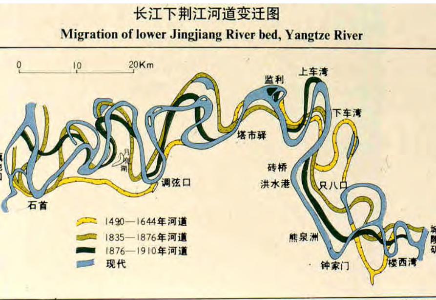
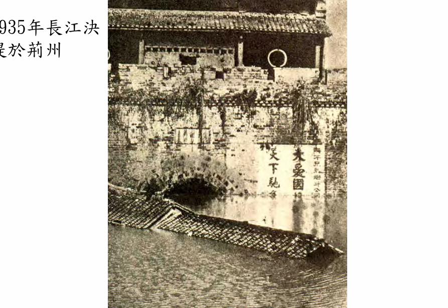
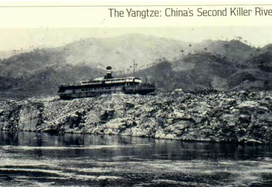
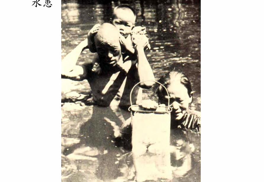
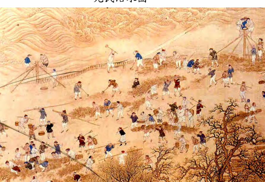
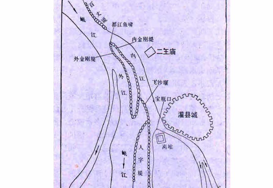
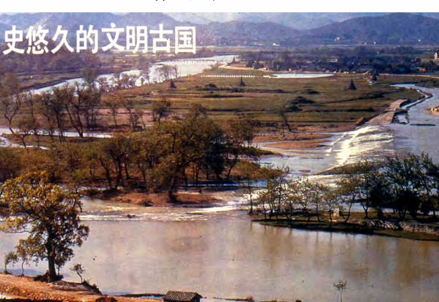
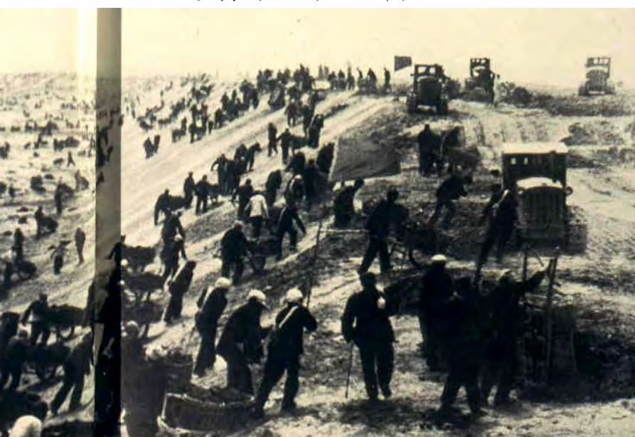
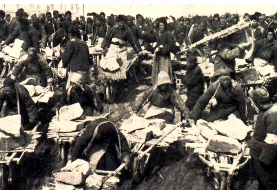
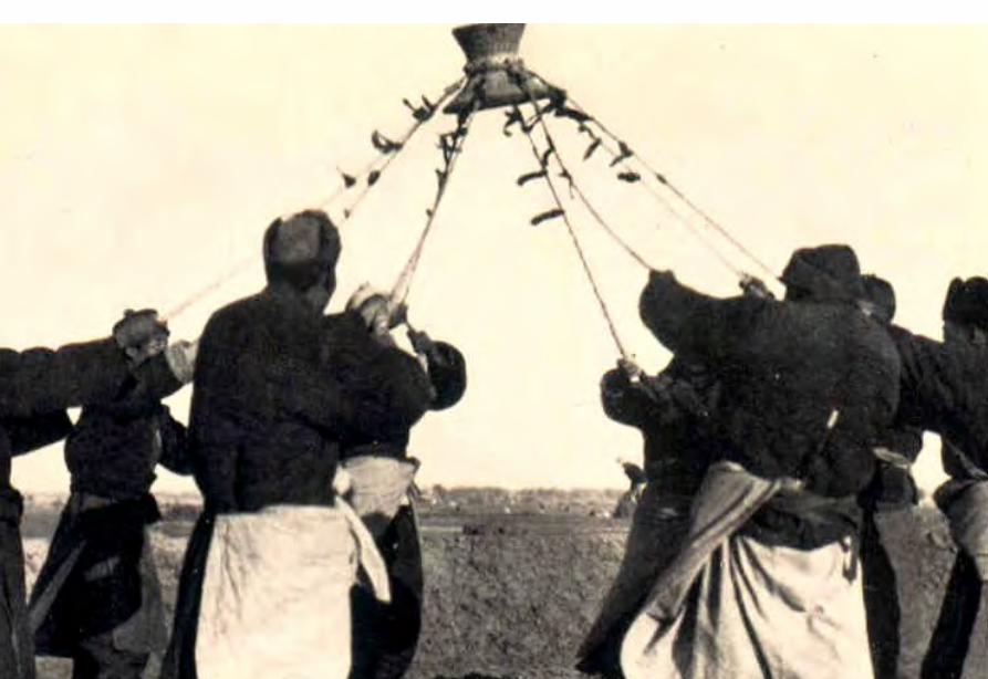
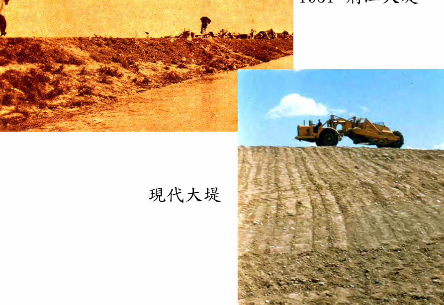
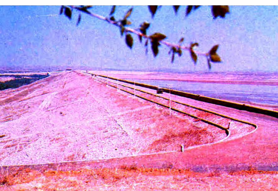
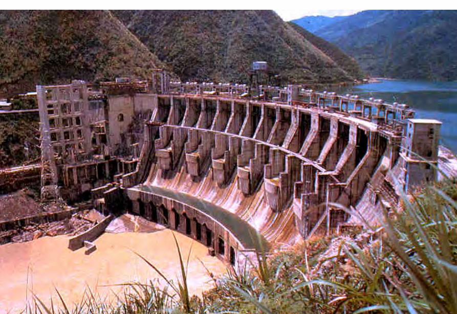
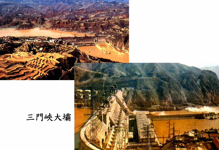
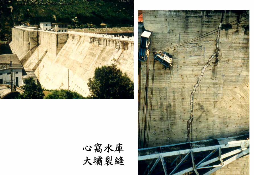
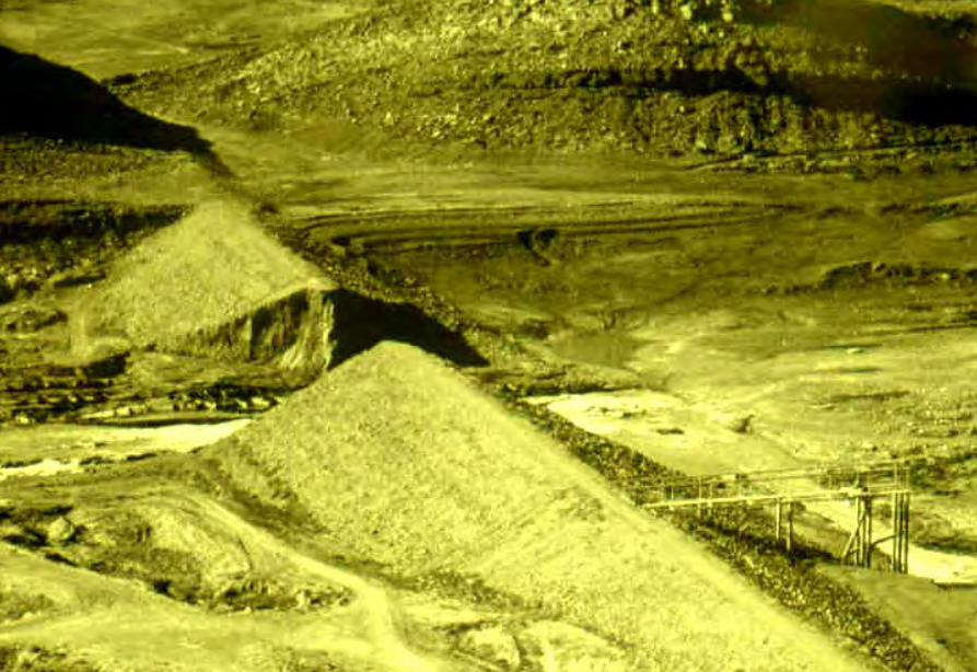
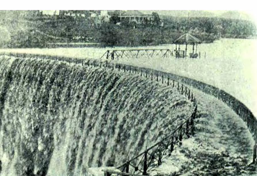
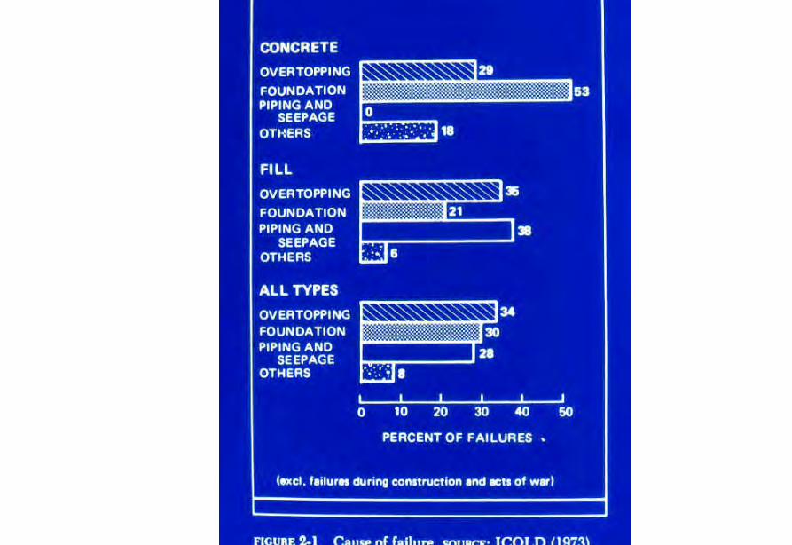
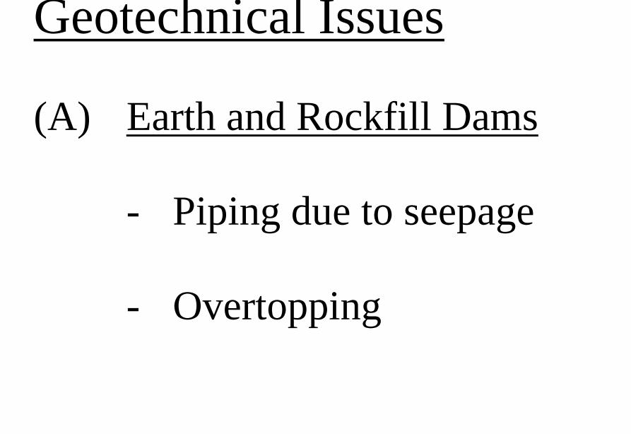
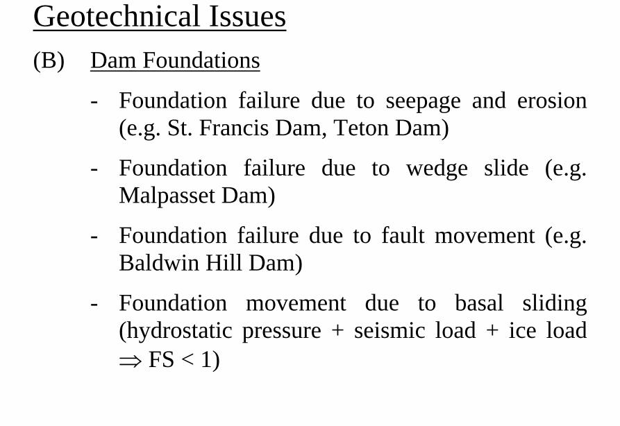
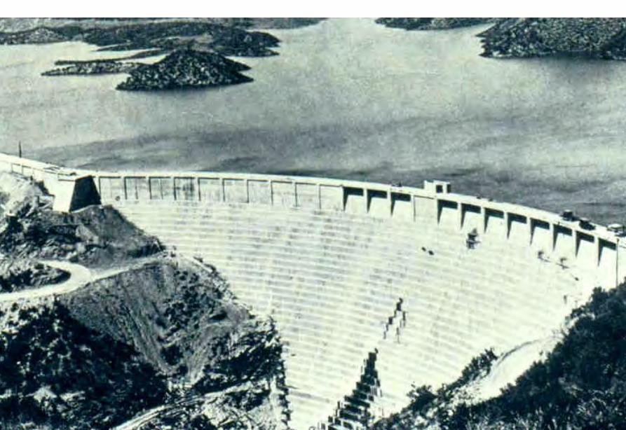
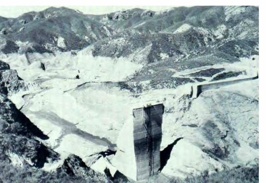
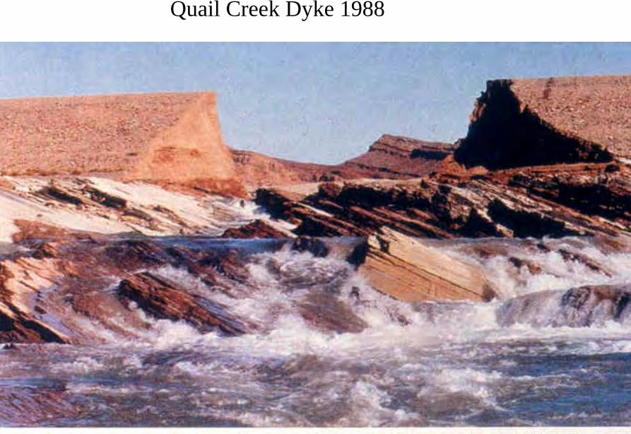
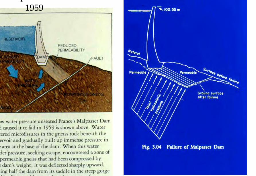
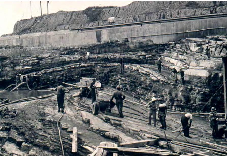
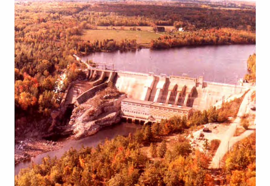
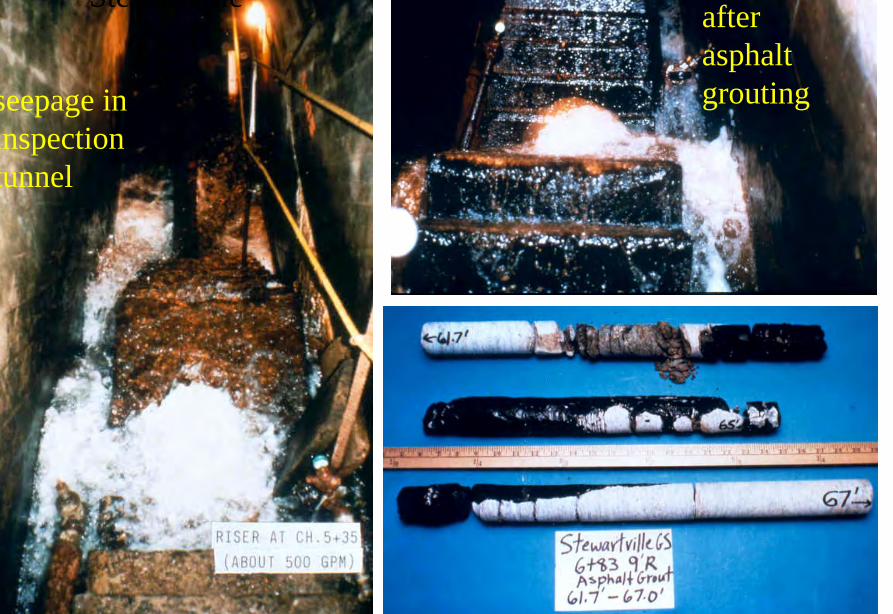
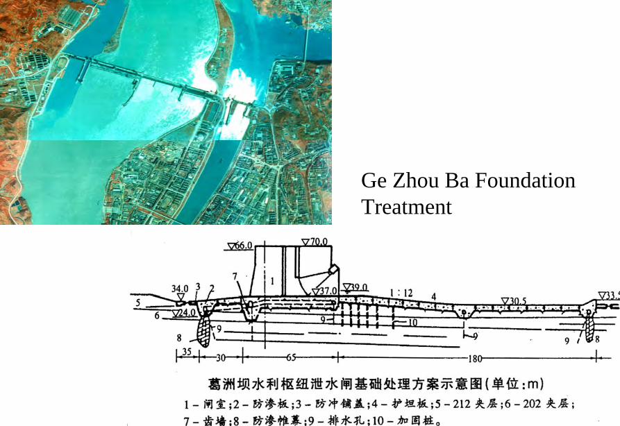
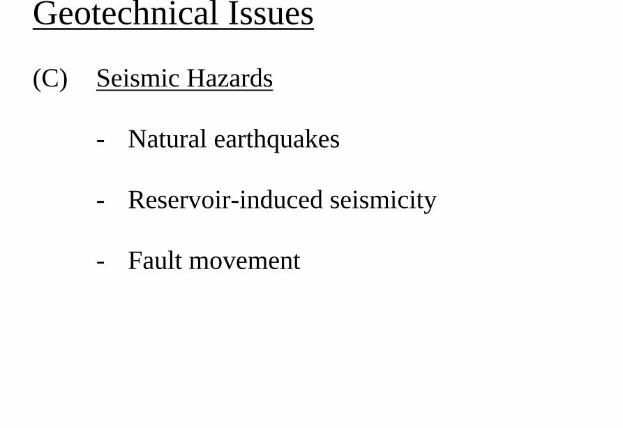
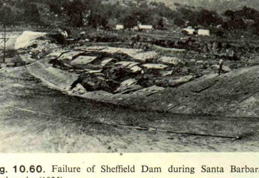
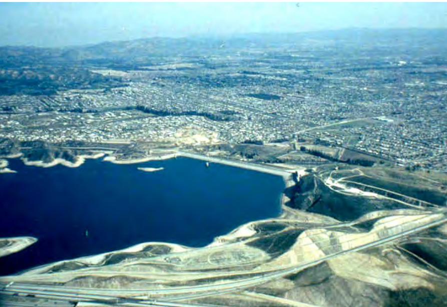
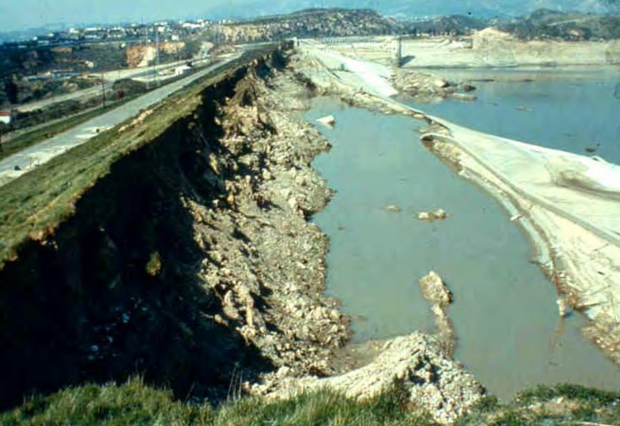
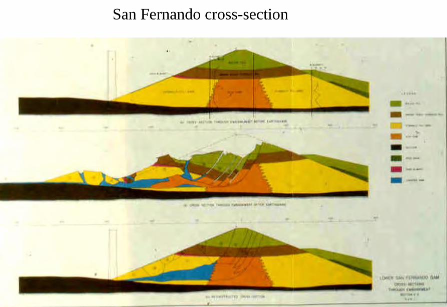
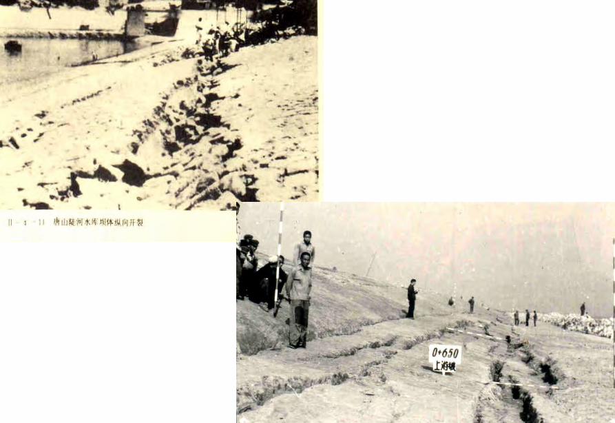
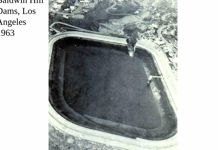
新豐江
新豐江
Geotechnical Issues (D) Reservoir Slopes
- Natural terrain landslides (eg Xintan) - Landslides due to reservoir impounding (eg
Vaiont Manwan Huanglungtan Zigui) - Landslide dams (eg Dadu River Usoi
Yigong)
Vaiont Dam
Vaiont Dam
Vaiont Dam
Vaiont Dam
Vaiont Dam
Vaiont Dam
Vaiont Dam
新灘滑坡
新灘滑坡
三峽秭歸千將坪滑坡
三峽巴東滑坡
鏈子崖加固工程
TGP Layout
TGP Layout
TGP Shiplock
TGP Shi l k
TGP Shiplock Section
TGP Shiplock Section
TGP Rock Core
TGP Rock Core
Man Wan Dam
Man Wan Landslide Site
The landslide of the Manwan Hydropower ProjectJanuary 8 1989
云南小湾水电站左岸坝前边坡
开挖时面貌
湖南五強溪水庫滑坡
Da Lake
Xiao Lake
Yinping dam
Rockfallsource
Da Lake
四川大渡河滑坡壩(1933年大地震)
MUDFLOW OF THE LONGYANGXIA POWER STATION
Time of occurrenceAugust 4 of 1997 at 2355
Cause of the incidentA 2-hour constant rainfall with a total precipitation of 55 mm
Source of the mudflow material Natural deposit and construction waste in the Beidagou Gully
龙羊峡水电站128万千瓦
Geotechnical Issues (E) Tunnels and Excavations in Rock
- Fracture-induced instability (rock mass
classification and tunnel support design) - Stress-induced instability - Time-dependent deformation (eg Niagara vs
Three Gorges shiplocks)
Hoover Dam
Hoover Dam
廣州抽水蓄能電站
Two Types of Instability Underground
bull Stress ndash controlledbull Fracture - controlled
Rock Mass Classifications
bull Rock Quality Designation (RQD)
bull Rock Mass Rating System (RMR)
bull Rock Tunnelling Quality Index (Q)
Class Qualitative description BQ Value
I Hard rock intact gt 550
II Hard rock relatively intactRelatively hard rock intact
550 ~ 451
III Hard rock relatively fracturedRelatively hard or interlayered of hard and weak rock relatively
intactRelatively weak rock intact
450 ~ 351
IV Hard rock fracturedRelatively hard rock fractured-relatively fracturedRelatively weak rock or interlayered of weak and hard rock with dominant
weak rock relatively intact or relatively fracturedWeak rock intact or relatively intact
350 ~ 251
V Relatively weak rock fracturedWeak rock fractured-relatively fracturedExtremely weak rock extremely fractured
lt 250
National Standard for Engineering Classification of Rock Masses (GB 50218-94)
Table 1 Basic quality (BQ) of rock mass
BQ = 90 + 3 Rc + 250 Kv
where Rc = uniaxial compressive strength (MPa)Kv = intactness index of rock mass
Table 2 Classification based on uniaxial compressive strength Rc
Rc (MPa) gt 60 60 ~ 30 30 ~ 15 15 ~ 5 lt 5
Description Hard rock Relatively hard rock
Relatively weak rock
Weak rock Extremely weak rock
Table 4 Intactness Factor Kv as a function of Joint Index Jv
Jv (number of joints
m3)
lt 3 3 ~ 10 10 ~ 20 20 ~ 35 gt 35
Kv gt 075 075 ~ 055 055 ~ 035 035 ~ 015 lt 015
Kv =
Vpm= in-situ velocity of longitudinal elastic wave (kms)
Vpr = velocity of longitudinal elastic wave in intact rock (kms)
2
pt
pm
VV
⎟⎟⎠
⎞⎜⎜⎝
⎛
For engineering classification use [BQ] amended for groundwater joint orientation and in-situ stress conditions
[BQ] = BQ ndash 100 (K1 + K2 + K3)
where BQ = basic quality
K1 = correction factor for groundwater
K2 = correction factor for orientation of planes of weakness
K3 = correction factor for in-situ stress conditions
Table 5 K1 values - Correction factor for groundwater conditions
gt450 450 ~ 351 350 ~251 lt250
Wet or drops 0 01 02 ~ 03 04 ~ 06
Shower or flowP lt 01 MPa
Q lt 10 L min m
01 02 ~ 03 04 ~ 06 07 ~ 09
Shower or flowP lt01 MPa
Q lt 10 L min m
02 10
BQK1
Groundwaterinflow
Table 6 K2 values - Correction factor for orientation of planes of weakness
Relation of structure plane to tunnel axis
α lt 30 o= 30 o ~ 75 o
α gt 30 oβ gt 75 o
Other combinations
K2 04 ~ 06 0 ~ 02 02 ~ 04
α - angle between strike of structure plane and tunnel axisβ - dipping angle of structure plane
Table 7 K3 values - Correction factor for in-situ stress conditions
gt 550 550 ~ 351 450 ~ 351 350 ~251 lt 250
Extremely high stress
10 10 10 ~ 15 10 ~ 15 10
High stress 05 05 05 05 ~ 10 05 ~ 10
BQK3
Initialstress state
Technical Specifications for Water Resources and Hydropower ProjectsRock Mass Rating for Tunnelling Projects
Rock class
Rock stability Host rock
rating
StrengthStress S Support type
I Stable long termstability generally no unstable block
100 ~ 85 gt 4 No support or locally bolting or thin shotcreting in case of large span systematic shotcrete bolt and meshII Basically stable no
plasticity deformation85 ~ 65 gt 4
if S lt 4go to III
III Poor stability locally plasticity deformation or collapse
65 ~ 45 gt 2if S lt 2go to IV
Systematic shotcrete bolt and mesh if span = 20 ~ 25 m concrete lining is needed
IV Unstable short self-standing time large scale collapse
45 ~ 25 gt 2if S lt 2go to V
Systematic shotcrete bolt and mesh and concrete lining
V Extremely unstable severe collapse
lt 25 No limits
Host rock rating (HRR) = A + B + C + D + E(somewhat similar to Bieniawskirsquos RMR)
Rating on rock strength (A)
Type of rock materialHard rock Weak rock
Hard rock Moderately hard rock
Relatively weak rock
Weak rock
Uniaxial strength of saturated rock (MPa)
100 ~ 60 60 ~ 30 30 ~ 15 15 ~ 5
Rating (A)Hard rock 30 ~ 20 20 ~ 10
Weak rock 10 ~ 5 5 ~ 0
For uniaxial strength σc gt 100 MPa rock mass rating is 30
Rating on rock intactness (B)
Intactness Intact Relatively intact
Poor intactness
Relatively fractured
Fractured
Intactness factor Kv 10 ~ 075 075 ~ 055 055 ~ 035 035 ~ 015 lt 015
Hard rock 40 ~ 30 30 ~ 22 22 ~ 14 14 ~ 6 lt 6
Weak rock 25 ~ 19 19 ~ 14 14 ~ 9 9 ~ 4 lt 4
Rating (B)
Rating on state of structure planes (C)
Aperture (mm) Filling Roughness evenness Hard rock Relatively weak rock Weak rock
Closed lt 05Undulating rough 27 27 18
Planar smooth 21 21 14
Slight open 05 ~ 50
No filling Undulating rough 24 24 17Undulating smooth or
planar rough21 21 14
Planar smooth 15 15 8
Slacks
Undulating rough 21 21 14
Undulating smooth or planar rough
17 17 11
Planar smooth 12 12 8
Mud
Undulating rough 15 15 10
Undulating smooth or planar rough
12 12 8
Open gt 50
Planar smooth 9 9 6
Slacks 12 12 8Mud 6 6 4
For a length of structure plane which is less than 3 m in hard rock and relatively weak rock rating would increase by 3 for weak rock rating would increase by 2 For length gt 10 m decrease rating by 3 and 2 respectively for hard rock and relatively weak rock If aperture gt 10 m without filling rating is 0
Rating on groundwater condition (D)
Basic rating(A + B + C)
State Wet Drops Linear Flow Flow
Quantity of flow
(Lminm)
lt 25or
lt 10
25-125or
10-100
gt 125or
gt 100
Water head(m)
100-85
Rating on Groundwater Conditions
(D)
0 0 -2 ~ -6
85-65 0 ~ -2 0 ~ -2 -6 ~ -10
65-45 -2 ~ -6 -2 ~ -6 -10 ~ -14
45 ~ 25 -6 ~ -10 -10 ~ -14 -14 ~ -18
lt 25 -10 ~ -14 -14 ~ -18 -18 ~ -20
Rating on orientation of structure planes (E)
Angle betweenstrike of
structure planeand tunnel axis
( o )
90o ~ 60o 60o ~ 30o lt 30o
Dipping angle( o )
gt70 75~45 45~20 lt20 gt70 75~45 45~20 45~20
Crown -2
Wall -5
-5
-2
-12-10-10
0 -2 -5
-5
-10
lt20 gt70 70~45 lt20
0 -2 -12
0
-12-10
-12 0
-5
-2 -5 -10
Rating (E)
Factor Basis for Rating Rating
Saturated Compressive Strength (MPa) gt100 100-60 60-30 30-15 15-5
Rating for A gt30 30-20 20-10 10-5 5-0
Intactness Coefficient 10-075 075-055 055-035 035-015 lt015
σc gt 30 MPa 40-30 30-22 22-14 14-5 lt6
σc lt 30 MPa
Degree of openness
Infillings
Polishness of surface
σc gt 60 MPa
σc 60 - 30 MPa 27-21 24-15 21-12 15-9 12-6
18-14 17-8 14-8 10-6 8-4
gt10m
-3
-2
100-85
σc lt 30 MPa
70o- 45o 45o- 20o lt20o
-5 -10
0-2
-2
-5
σc gt 60 MPa
σc lt 60 MPa
Seeping dripping 0
Linear flow 0 rarr -2
-2 rarr -6
90o - 60o
gt70o
Roof 0
Sidewall -2
Gush of water
25-19 19-14 14-9 9-4 lt4
Closed lt05mm
Slightly open 05 ndash 50 mm Open gt 5 mm
Nil Rock fragments
Clay Fragmented Clay
Flat polished to curved rough
27-21 24-15 21-12 15-9 12-6
Length of structural surface lt3 m 3-10 m
+3 0
+2 0
A + B + C1 + C2 Rating 85-65 64-45 45-25 lt25
0 rarr -2 -2 rarr -6 -6 rarr -10 -10 rarr -14
-2 rarr -6 -6 rarr -10 -10 rarr -14 -14 rarr -18
-6 rarr -10 -10 rarr -14 -14 rarr -18 -18 rarr -20
Angle between tunnel alignment and structural orientation (strike)
60o - 30o lt 30o
Dip of structural orientation gt 70o 70o - 4 5o 45o - 20o lt 20o gt 70o 70o - 45o 45o - 20o lt 20o
2 -5 -10 -12 -5 -10 -12 -12
-5 -10 -2 0 -10 -12 -5 0
Rating for E
E
Rating for D
D
Rating for C2
C2
Rating for C1
Structural surface condition
C1
Rating for B
B
A
Host Rock Rating (HRR)
Recommended rock parameters
Class Gravity density γ(kNm3)
Friction angle ϕ (o)
Cohesion C(MPa)
Deformation module E(MPa)
Poisson ratio ν
I gt 60 gt 21 gt 33 lt 02
II 60 ~ 50 21 ~ 15 33 ~ 20 02 ~ 025
III 265 ~ 245 50 ~ 39 15 ~ 07 20 ~ 6 025 ~ 03
IV 245 ~ 225 39 ~ 27 07 ~ 02 6 ~ 13 03 ~ 035
V lt 225 lt 27 lt 02 lt 13 gt 035
gt 265
Recommended rock strength parameters
ClassConcrete-rock contact Rock mass Deformation
modulus
fprime cprime (MPa) fprime cprime (MPa) E0 X 104 (MPa)
I 15 ~ 13 15 ~ 13 16 ~ 14 25 ~ 20 gt 20
II 13 ~ 11 13 ~ 11 14 ~ 12 20 ~ 15 20 ~ 10
III 11 ~ 09 11 ~ 07 12 ~ 08 15 ~ 07 10 ~ 05
IV 09 ~ 07 07 ~ 03 08 ~ 055 07 ~ 03 05 ~ 02
V 07 ~ 04 03 ~ 005 055 ~ 040 03 ~ 005 02 ~ 002
fprime cprime - Shear strength
Design Applications of HRR
Rock PropertiesRock Type
Rock Mass Stability Host Rock
Rating (HRR)
Strength vs Stress Ratio (S) f C (MPa) E(x 104MPa)
Support Requirements
I Stable with long-term stability no unstable blocks in general
100 - 85 16 - 14 25 - 20 gt 20 Unsupported or localized boltsshotcrete or thin shotcrete add wire mesh for tunnels with large span
II Essentially stable with overall stability no plastic deformation localized rockfall
85 - 65 Downgrade to III for S lt 4
14 - 12 20 - 15 20 - 10
III Poor stability localized plastic deformation cave-in if unsupported temporarily stable in intact relatively soft rock
65 - 45 Downgrade to IV for S lt 2
12 - 08 15 - 07 10 - 05 Bolts and shotcrete with wire mesh concrete lining for tunnel span of 20 -25 m
IV Unstable very short standup time relatively large deformationfailure may occur
45 - 25 Downgrade to V for S lt 1
08 - 055 07 - 03 05 - 02 Bolts and shotcrete with re-bar mesh and concrete lining
V Very unstable could not stand up severe deformationfailure
lt 25 055 - 040 03 - 005 02 - 002
SUPPORT PARAMETERS(National Standard for Design of Bolt-shotcrete Support)
Span (m)Rock Class
B lt 5 m 5 lt B lt 10 10 lt B lt 20 15 lt B lt 20 20 lt B lt 25 m
I No support Shotcrete50 mm
(1) Shotcrete 80-100 mm(2) Shotcrete 50 mmbolt 20-25 m
Shotcrete Shotcrete 120-150 mmwith mesh bolt 30-40 m
II Shotcrete50 mm
(1) Shotcrete 80-100 mm(2) Shotcrete 50 mmbolt 15-2m
(1) Shotcrete 120-150 mm mesh if necessary(2) Shotcrete 80-120 mmbolt 2-3 m mesh if necessary
Shotcrete 120-150 mmmesh bolt 25-30 m
Shotcrete 150-200 mmmesh bolt 3-4 m
III (1) Shotcrete 80-100 mm(2) Shotcrete 50 mmbolt 15-2 m
(1) Shotcrete 120-150 mm mesh if necessary(2) Shotcrete 80-120 mmbolt 2-3 m mesh if necessary
Shotcrete 100-150 mmmesh bolt 20-30 m
Shotcrete 150-200 mmmesh bolt 3-4 m
IV Shotcrete 80-100 mmbolt 15-20 m
Shotcrete 100-200 mmmesh bolt 20-25 m bottom arch if necessary
Shotcrete 150-200 mmmesh bolt 25-30 m bottom arch if necessary
V Shotcrete 120-150 mmmesh bolt 15-20 m bottom arch if necessary
Shotcrete 150-200 mmmesh bolt 20-30 m bottom frame if necessary
GB-J86-85 (Revised)
Comparison of Rock Mass Classification Systems
System Range of Classes
Main Factors
Q 001-1000
9 RQD Jn (joint set number) Jr (joint roughness number) Ja (joint alteration number) Stress reduction factor SRF
RMR 0-100 5 Rock strength RQD Spacing conditions and orientation of joints Groundwater
HRR 0-100 5 Rock strength Intactness Conditions and Orientation of Weakness Planes Groundwater Initial Stresses
BQ lt 250-gt 500
5 Rock strength Intactness Groundwater Orientation of Weakness Planes Initial Stresses
Important Factors that are common among the various systems
1 Rock strength
2 Intactness
3 Condition of planes of weakness
4 Groundwater
5 Orientation of discontinuities
6 Initial stresses
Support systems for underground excavations in ChinaRock Class Span (m) Shotcrete Steel Mesh Bolt Concrete Lining
Total Number
of Projects
Thickness (cm)
Diameters(mm)
Spacing (m)
Diameter (mm)
Length (m)
Spacing (m)
Thickness(cm)
Number of Works
I 5-10 3-15 no no 18-22 12-30 Random no 9
10-15 3-20 6-12 025-15 18-22 15-35 10-15 no 9
15-20 10-20 no no 20-22 10-30 10-15 no 3
II 5-10 5-15 6-10 02-13 16-20 12-21 10-12 no 2 10
10-15 4-20 6-18 02-13 18-22 15-35 08-15 30-50 13
15-20 8-16 8-12 02-13 16-32 20-40 12-15 no 10
III 5-10 5-20 6-10 02-10 18-22 16-30 10-15 wall 1 12
10-15 5-20 5-12 02-10 16-24 15-35 10-15 11
15-20 10-16 6-12 02-08 16-30 20-40 08-12 8
IV 5-10 15-20 6-14 02-025 18-22 18-40 075-125 40 4 10
10-15 5-20 6-12 02-03 16-22 25-40 08-125 50 2 5
15-20 20 10-19 025 22 20 12 1
V 5-10 10-15 8-14 02-025 16-22 15-36 08-12 40 2
4
7
10-15 18-20 6-12 02-03 20-22 25-35 08-10 60 4
Three Gorges ProjectAmended [BQ] Values for Granite
Maximum [BQ]max = 630
Minimum [BQ]min = 500
Average [BQ]mean = 565
Class I- to II+
Guangzhou Pumped Storage Project
bull Location north of Guangzhou Guangdong Province
bull Underground Powerhouse
1465 m x 22 m x 445 m (L x W x H)
at 330 - 400 m depth completed in 1993
bull Host Rock Biotite granite
bull Support System Bolts (at 2 x 15 m spacing)+ 15 cm shotcrete in both crown and
sidewalls
Xiaolangdi Project
bull Location on Yellow River Henan Provincebull Underground Powerhouse
2515 m x 262 m x 614m (L x W x H)At 70 ndash 100 m depth completed in 1999
bull Host Rock Sandstone with argillaceous bedsbull Support System Bolts (at 15 spacing) with wiremesh
and shotcret (20 cm) in crownBolts (at 15 spacing) in sidewallsAnchors locally where required
Xiaolangdi Project on Yellow RiverProposed support parameters in design stage
Support DesignCavern Type Location Rock Type
Rock Grade Tensile Bolt Re Shotcrete
Top T14 III Φ 25 15 X 15 m (mortar bolt)
L = 53 m (alternatively)Φ 6 20 X 20 cmδ = 10 cm (C20)
Tailrace Cavern
Top T14 III Φ 28 15 X 15 m
L = 84 m (alternatively)Φ 8 20 X 20 cmδ = 20 cm (C20)
Sidewall T14
T13-2
III Φ 25 15 X 15 mL = 128 m (alternatively)
Φ 8 20 X 20 cmδ = 15 cm (C20)
Top T14 II- Φ 25 15 X 15 m
L = 73 m (alternatively)Φ 6 20 X 20 cmδ = 15 cm (C20)
Sidewall T14 II- Φ 25 15 X 15 m
L = 53 m (alternatively)Φ 6 20 X 20 cmδ = 10 cm (C20)
Sidewall T14 III Φ 25 15 X 15 m (mortar bolt)
L = 4 mΦ 6 25 X 25 cmδ = 10 cm (C20)
Transformer Cavern
Main Power-house
T14 thick to massive siliceous fine-grained sandstone
T13-2 thick to massive argillaceous and calcareous silty fine-grained sandstone
Xiaolangdi Project on Yellow RiverActual support used at construction stage
Support DesignCavern Type Location Rock Type
Rock Grade Tensile Bolt Re Shotcrete
Support Pres
(MPa)0112
0056
0104
0104
056
0044
Top T14 III Φ 32 3 X 3 m L = 5 m P = 150 KN
Φ 32 3 X 3 m L = 3 m P = 150 KNΦ 6 25 X 25 cmδ = 15 cm (C20)
Tailrace Cavern
Top T14 III Φ 32 3 X 3 m L = 8 m P = 150 KN
Φ 32 3 X 3 m L = 6 m P = 150 KNCable L = 25 m 45 X 6 m P = 1500 KN
Φ 8 20 X 20 cmδ = 20 cm (C20)
Sidewall T14
T13-2
III Φ 32 3 X 3 m L = 10 m P = 150 KNΦ 32 3 X 3 m L = 6 m P = 150 KNTwo rows of pre-stressed bolt added for argillized interlayers 500 KN L = 15 m
Φ 8 20 X 20 cmδ = 20 cm (C20)
Top T14 II- Φ 32 24 X 24 m L = 8 m P = 150 KN
Φ 32 24 X 24 m L = 4 m P = 150 KNΦ 6 20 X 20 cmδ = 20 cm (C20)
Sidewall T14 II- Φ 32 24 X 24 m L = 6 m P = 150 KN
Φ 32 24 X 24 m L = 4 m P = 150 KNΦ 6 25 X 25 cmδ = 15 cm (C20)
Sidewall T14 III Φ 32 15 X 15 m
L = 4 m P = 100 KNΦ 6 25 X 25 cmδ = 10 cm (C20)
Transformer Cavern
Main Power-house
Er Tan Dam
Er Tan Dam
Er Tan Dam Layout
Er Tan Dam Layout
Er Tan Under Construction
Er Tan Under Construction
Er Tan Underground Power House
Er Tan Underground Power House
Er Tan Diversion Tunnel
Er Tan Diversion Tunnel
Er Tan Rock Discing
Er Tan Rock Discing
Er Tan Geostress
Er Tan Geostress(kgcm2)
Strain Energy Approach to Modelling Rock Squeeze Problems
For a virtual displacement δ e
Work Done = Force x Displacement = Feδ e = (δ e)TFe
where Fe = corresponding nodal force Strain energy recovered from unit volume of rock = Stress x Strain = σ ε = ε Tσ = ([B] δ e)T ([D]ε ) = (δ e)T[B][D] ε Work Done = Strain Energy Released (δ e)TFe = (δ e)T int vol [B]T[D] ε dv
or Fe = int vol [B]T[D] ε dv
Some Features of Chinese Hydro Projects
bull Same design framework as in the Westbull Very detailed site investigationsbull Including numerous aditsbull Sometimes leads to significant cost savingsbull (eg Ertan dam allowed to be founded on Class III
rock instead of Class II as called for by Design Standard
bull Strong emphasis on geology and rock mass structure studies
bull Very detailed analysis including numerical modelling AI etc
青海龍羊峽
青海 黃河 李家峽 拱壩壩址
青海 李家峽
探洞
滑面
滑面
李家峽水庫 老滑坡體
剖面
電力需求增長
水電資源
Schematic Map of Hydropower Stations of 1GW and above in Operation or Under Construction
Jin Sha River Hydro Power
南水北調三線
Method of Generation Pros Cons
Capital Construction Cost
(Ratio) Fuel Cost
Fossil
bull Short construction period (2-3 years)
bull Easy to start up
bull Air pollution bull Ashsludge
disposal 1 Relatively high
Hydraulic
bull Longer construction period (gt 5 years)
bull Resettlement of affected population
bull Preservation of cultural amp historic relics
2
Nuclear
bull Relatively long construction period (ge 10 years)
bull Nuclear safety concern
bull Nuclear waste disposal needs
5 Relatively low
Other generation methods solar wind biomass etc
The Joy of being a Hydro Project Engineer
bull Free helicopter jet rides(safe most of the time)
bull Exotic places with breathtaking scenerysceneryand colorful folklore(no tourists around no phone calls etc)
攔路酒(四川 涼山)
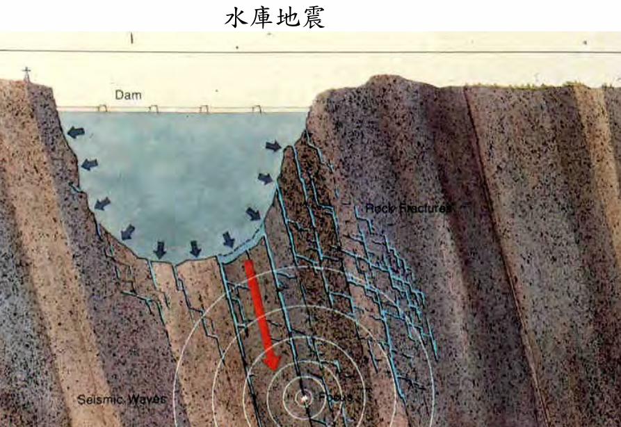
新豐江
Geotechnical Issues (D) Reservoir Slopes
- Natural terrain landslides (eg Xintan) - Landslides due to reservoir impounding (eg
Vaiont Manwan Huanglungtan Zigui) - Landslide dams (eg Dadu River Usoi
Yigong)
Vaiont Dam
Vaiont Dam
Vaiont Dam
Vaiont Dam
Vaiont Dam
Vaiont Dam
Vaiont Dam
新灘滑坡
新灘滑坡
三峽秭歸千將坪滑坡
三峽巴東滑坡
鏈子崖加固工程
TGP Layout
TGP Layout
TGP Shiplock
TGP Shi l k
TGP Shiplock Section
TGP Shiplock Section
TGP Rock Core
TGP Rock Core
Man Wan Dam
Man Wan Landslide Site
The landslide of the Manwan Hydropower ProjectJanuary 8 1989
云南小湾水电站左岸坝前边坡
开挖时面貌
湖南五強溪水庫滑坡
Da Lake
Xiao Lake
Yinping dam
Rockfallsource
Da Lake
四川大渡河滑坡壩(1933年大地震)
MUDFLOW OF THE LONGYANGXIA POWER STATION
Time of occurrenceAugust 4 of 1997 at 2355
Cause of the incidentA 2-hour constant rainfall with a total precipitation of 55 mm
Source of the mudflow material Natural deposit and construction waste in the Beidagou Gully
龙羊峡水电站128万千瓦
Geotechnical Issues (E) Tunnels and Excavations in Rock
- Fracture-induced instability (rock mass
classification and tunnel support design) - Stress-induced instability - Time-dependent deformation (eg Niagara vs
Three Gorges shiplocks)
Hoover Dam
Hoover Dam
廣州抽水蓄能電站
Two Types of Instability Underground
bull Stress ndash controlledbull Fracture - controlled
Rock Mass Classifications
bull Rock Quality Designation (RQD)
bull Rock Mass Rating System (RMR)
bull Rock Tunnelling Quality Index (Q)
Class Qualitative description BQ Value
I Hard rock intact gt 550
II Hard rock relatively intactRelatively hard rock intact
550 ~ 451
III Hard rock relatively fracturedRelatively hard or interlayered of hard and weak rock relatively
intactRelatively weak rock intact
450 ~ 351
IV Hard rock fracturedRelatively hard rock fractured-relatively fracturedRelatively weak rock or interlayered of weak and hard rock with dominant
weak rock relatively intact or relatively fracturedWeak rock intact or relatively intact
350 ~ 251
V Relatively weak rock fracturedWeak rock fractured-relatively fracturedExtremely weak rock extremely fractured
lt 250
National Standard for Engineering Classification of Rock Masses (GB 50218-94)
Table 1 Basic quality (BQ) of rock mass
BQ = 90 + 3 Rc + 250 Kv
where Rc = uniaxial compressive strength (MPa)Kv = intactness index of rock mass
Table 2 Classification based on uniaxial compressive strength Rc
Rc (MPa) gt 60 60 ~ 30 30 ~ 15 15 ~ 5 lt 5
Description Hard rock Relatively hard rock
Relatively weak rock
Weak rock Extremely weak rock
Table 4 Intactness Factor Kv as a function of Joint Index Jv
Jv (number of joints
m3)
lt 3 3 ~ 10 10 ~ 20 20 ~ 35 gt 35
Kv gt 075 075 ~ 055 055 ~ 035 035 ~ 015 lt 015
Kv =
Vpm= in-situ velocity of longitudinal elastic wave (kms)
Vpr = velocity of longitudinal elastic wave in intact rock (kms)
2
pt
pm
VV
⎟⎟⎠
⎞⎜⎜⎝
⎛
For engineering classification use [BQ] amended for groundwater joint orientation and in-situ stress conditions
[BQ] = BQ ndash 100 (K1 + K2 + K3)
where BQ = basic quality
K1 = correction factor for groundwater
K2 = correction factor for orientation of planes of weakness
K3 = correction factor for in-situ stress conditions
Table 5 K1 values - Correction factor for groundwater conditions
gt450 450 ~ 351 350 ~251 lt250
Wet or drops 0 01 02 ~ 03 04 ~ 06
Shower or flowP lt 01 MPa
Q lt 10 L min m
01 02 ~ 03 04 ~ 06 07 ~ 09
Shower or flowP lt01 MPa
Q lt 10 L min m
02 10
BQK1
Groundwaterinflow
Table 6 K2 values - Correction factor for orientation of planes of weakness
Relation of structure plane to tunnel axis
α lt 30 o= 30 o ~ 75 o
α gt 30 oβ gt 75 o
Other combinations
K2 04 ~ 06 0 ~ 02 02 ~ 04
α - angle between strike of structure plane and tunnel axisβ - dipping angle of structure plane
Table 7 K3 values - Correction factor for in-situ stress conditions
gt 550 550 ~ 351 450 ~ 351 350 ~251 lt 250
Extremely high stress
10 10 10 ~ 15 10 ~ 15 10
High stress 05 05 05 05 ~ 10 05 ~ 10
BQK3
Initialstress state
Technical Specifications for Water Resources and Hydropower ProjectsRock Mass Rating for Tunnelling Projects
Rock class
Rock stability Host rock
rating
StrengthStress S Support type
I Stable long termstability generally no unstable block
100 ~ 85 gt 4 No support or locally bolting or thin shotcreting in case of large span systematic shotcrete bolt and meshII Basically stable no
plasticity deformation85 ~ 65 gt 4
if S lt 4go to III
III Poor stability locally plasticity deformation or collapse
65 ~ 45 gt 2if S lt 2go to IV
Systematic shotcrete bolt and mesh if span = 20 ~ 25 m concrete lining is needed
IV Unstable short self-standing time large scale collapse
45 ~ 25 gt 2if S lt 2go to V
Systematic shotcrete bolt and mesh and concrete lining
V Extremely unstable severe collapse
lt 25 No limits
Host rock rating (HRR) = A + B + C + D + E(somewhat similar to Bieniawskirsquos RMR)
Rating on rock strength (A)
Type of rock materialHard rock Weak rock
Hard rock Moderately hard rock
Relatively weak rock
Weak rock
Uniaxial strength of saturated rock (MPa)
100 ~ 60 60 ~ 30 30 ~ 15 15 ~ 5
Rating (A)Hard rock 30 ~ 20 20 ~ 10
Weak rock 10 ~ 5 5 ~ 0
For uniaxial strength σc gt 100 MPa rock mass rating is 30
Rating on rock intactness (B)
Intactness Intact Relatively intact
Poor intactness
Relatively fractured
Fractured
Intactness factor Kv 10 ~ 075 075 ~ 055 055 ~ 035 035 ~ 015 lt 015
Hard rock 40 ~ 30 30 ~ 22 22 ~ 14 14 ~ 6 lt 6
Weak rock 25 ~ 19 19 ~ 14 14 ~ 9 9 ~ 4 lt 4
Rating (B)
Rating on state of structure planes (C)
Aperture (mm) Filling Roughness evenness Hard rock Relatively weak rock Weak rock
Closed lt 05Undulating rough 27 27 18
Planar smooth 21 21 14
Slight open 05 ~ 50
No filling Undulating rough 24 24 17Undulating smooth or
planar rough21 21 14
Planar smooth 15 15 8
Slacks
Undulating rough 21 21 14
Undulating smooth or planar rough
17 17 11
Planar smooth 12 12 8
Mud
Undulating rough 15 15 10
Undulating smooth or planar rough
12 12 8
Open gt 50
Planar smooth 9 9 6
Slacks 12 12 8Mud 6 6 4
For a length of structure plane which is less than 3 m in hard rock and relatively weak rock rating would increase by 3 for weak rock rating would increase by 2 For length gt 10 m decrease rating by 3 and 2 respectively for hard rock and relatively weak rock If aperture gt 10 m without filling rating is 0
Rating on groundwater condition (D)
Basic rating(A + B + C)
State Wet Drops Linear Flow Flow
Quantity of flow
(Lminm)
lt 25or
lt 10
25-125or
10-100
gt 125or
gt 100
Water head(m)
100-85
Rating on Groundwater Conditions
(D)
0 0 -2 ~ -6
85-65 0 ~ -2 0 ~ -2 -6 ~ -10
65-45 -2 ~ -6 -2 ~ -6 -10 ~ -14
45 ~ 25 -6 ~ -10 -10 ~ -14 -14 ~ -18
lt 25 -10 ~ -14 -14 ~ -18 -18 ~ -20
Rating on orientation of structure planes (E)
Angle betweenstrike of
structure planeand tunnel axis
( o )
90o ~ 60o 60o ~ 30o lt 30o
Dipping angle( o )
gt70 75~45 45~20 lt20 gt70 75~45 45~20 45~20
Crown -2
Wall -5
-5
-2
-12-10-10
0 -2 -5
-5
-10
lt20 gt70 70~45 lt20
0 -2 -12
0
-12-10
-12 0
-5
-2 -5 -10
Rating (E)
Factor Basis for Rating Rating
Saturated Compressive Strength (MPa) gt100 100-60 60-30 30-15 15-5
Rating for A gt30 30-20 20-10 10-5 5-0
Intactness Coefficient 10-075 075-055 055-035 035-015 lt015
σc gt 30 MPa 40-30 30-22 22-14 14-5 lt6
σc lt 30 MPa
Degree of openness
Infillings
Polishness of surface
σc gt 60 MPa
σc 60 - 30 MPa 27-21 24-15 21-12 15-9 12-6
18-14 17-8 14-8 10-6 8-4
gt10m
-3
-2
100-85
σc lt 30 MPa
70o- 45o 45o- 20o lt20o
-5 -10
0-2
-2
-5
σc gt 60 MPa
σc lt 60 MPa
Seeping dripping 0
Linear flow 0 rarr -2
-2 rarr -6
90o - 60o
gt70o
Roof 0
Sidewall -2
Gush of water
25-19 19-14 14-9 9-4 lt4
Closed lt05mm
Slightly open 05 ndash 50 mm Open gt 5 mm
Nil Rock fragments
Clay Fragmented Clay
Flat polished to curved rough
27-21 24-15 21-12 15-9 12-6
Length of structural surface lt3 m 3-10 m
+3 0
+2 0
A + B + C1 + C2 Rating 85-65 64-45 45-25 lt25
0 rarr -2 -2 rarr -6 -6 rarr -10 -10 rarr -14
-2 rarr -6 -6 rarr -10 -10 rarr -14 -14 rarr -18
-6 rarr -10 -10 rarr -14 -14 rarr -18 -18 rarr -20
Angle between tunnel alignment and structural orientation (strike)
60o - 30o lt 30o
Dip of structural orientation gt 70o 70o - 4 5o 45o - 20o lt 20o gt 70o 70o - 45o 45o - 20o lt 20o
2 -5 -10 -12 -5 -10 -12 -12
-5 -10 -2 0 -10 -12 -5 0
Rating for E
E
Rating for D
D
Rating for C2
C2
Rating for C1
Structural surface condition
C1
Rating for B
B
A
Host Rock Rating (HRR)
Recommended rock parameters
Class Gravity density γ(kNm3)
Friction angle ϕ (o)
Cohesion C(MPa)
Deformation module E(MPa)
Poisson ratio ν
I gt 60 gt 21 gt 33 lt 02
II 60 ~ 50 21 ~ 15 33 ~ 20 02 ~ 025
III 265 ~ 245 50 ~ 39 15 ~ 07 20 ~ 6 025 ~ 03
IV 245 ~ 225 39 ~ 27 07 ~ 02 6 ~ 13 03 ~ 035
V lt 225 lt 27 lt 02 lt 13 gt 035
gt 265
Recommended rock strength parameters
ClassConcrete-rock contact Rock mass Deformation
modulus
fprime cprime (MPa) fprime cprime (MPa) E0 X 104 (MPa)
I 15 ~ 13 15 ~ 13 16 ~ 14 25 ~ 20 gt 20
II 13 ~ 11 13 ~ 11 14 ~ 12 20 ~ 15 20 ~ 10
III 11 ~ 09 11 ~ 07 12 ~ 08 15 ~ 07 10 ~ 05
IV 09 ~ 07 07 ~ 03 08 ~ 055 07 ~ 03 05 ~ 02
V 07 ~ 04 03 ~ 005 055 ~ 040 03 ~ 005 02 ~ 002
fprime cprime - Shear strength
Design Applications of HRR
Rock PropertiesRock Type
Rock Mass Stability Host Rock
Rating (HRR)
Strength vs Stress Ratio (S) f C (MPa) E(x 104MPa)
Support Requirements
I Stable with long-term stability no unstable blocks in general
100 - 85 16 - 14 25 - 20 gt 20 Unsupported or localized boltsshotcrete or thin shotcrete add wire mesh for tunnels with large span
II Essentially stable with overall stability no plastic deformation localized rockfall
85 - 65 Downgrade to III for S lt 4
14 - 12 20 - 15 20 - 10
III Poor stability localized plastic deformation cave-in if unsupported temporarily stable in intact relatively soft rock
65 - 45 Downgrade to IV for S lt 2
12 - 08 15 - 07 10 - 05 Bolts and shotcrete with wire mesh concrete lining for tunnel span of 20 -25 m
IV Unstable very short standup time relatively large deformationfailure may occur
45 - 25 Downgrade to V for S lt 1
08 - 055 07 - 03 05 - 02 Bolts and shotcrete with re-bar mesh and concrete lining
V Very unstable could not stand up severe deformationfailure
lt 25 055 - 040 03 - 005 02 - 002
SUPPORT PARAMETERS(National Standard for Design of Bolt-shotcrete Support)
Span (m)Rock Class
B lt 5 m 5 lt B lt 10 10 lt B lt 20 15 lt B lt 20 20 lt B lt 25 m
I No support Shotcrete50 mm
(1) Shotcrete 80-100 mm(2) Shotcrete 50 mmbolt 20-25 m
Shotcrete Shotcrete 120-150 mmwith mesh bolt 30-40 m
II Shotcrete50 mm
(1) Shotcrete 80-100 mm(2) Shotcrete 50 mmbolt 15-2m
(1) Shotcrete 120-150 mm mesh if necessary(2) Shotcrete 80-120 mmbolt 2-3 m mesh if necessary
Shotcrete 120-150 mmmesh bolt 25-30 m
Shotcrete 150-200 mmmesh bolt 3-4 m
III (1) Shotcrete 80-100 mm(2) Shotcrete 50 mmbolt 15-2 m
(1) Shotcrete 120-150 mm mesh if necessary(2) Shotcrete 80-120 mmbolt 2-3 m mesh if necessary
Shotcrete 100-150 mmmesh bolt 20-30 m
Shotcrete 150-200 mmmesh bolt 3-4 m
IV Shotcrete 80-100 mmbolt 15-20 m
Shotcrete 100-200 mmmesh bolt 20-25 m bottom arch if necessary
Shotcrete 150-200 mmmesh bolt 25-30 m bottom arch if necessary
V Shotcrete 120-150 mmmesh bolt 15-20 m bottom arch if necessary
Shotcrete 150-200 mmmesh bolt 20-30 m bottom frame if necessary
GB-J86-85 (Revised)
Comparison of Rock Mass Classification Systems
System Range of Classes
Main Factors
Q 001-1000
9 RQD Jn (joint set number) Jr (joint roughness number) Ja (joint alteration number) Stress reduction factor SRF
RMR 0-100 5 Rock strength RQD Spacing conditions and orientation of joints Groundwater
HRR 0-100 5 Rock strength Intactness Conditions and Orientation of Weakness Planes Groundwater Initial Stresses
BQ lt 250-gt 500
5 Rock strength Intactness Groundwater Orientation of Weakness Planes Initial Stresses
Important Factors that are common among the various systems
1 Rock strength
2 Intactness
3 Condition of planes of weakness
4 Groundwater
5 Orientation of discontinuities
6 Initial stresses
Support systems for underground excavations in ChinaRock Class Span (m) Shotcrete Steel Mesh Bolt Concrete Lining
Total Number
of Projects
Thickness (cm)
Diameters(mm)
Spacing (m)
Diameter (mm)
Length (m)
Spacing (m)
Thickness(cm)
Number of Works
I 5-10 3-15 no no 18-22 12-30 Random no 9
10-15 3-20 6-12 025-15 18-22 15-35 10-15 no 9
15-20 10-20 no no 20-22 10-30 10-15 no 3
II 5-10 5-15 6-10 02-13 16-20 12-21 10-12 no 2 10
10-15 4-20 6-18 02-13 18-22 15-35 08-15 30-50 13
15-20 8-16 8-12 02-13 16-32 20-40 12-15 no 10
III 5-10 5-20 6-10 02-10 18-22 16-30 10-15 wall 1 12
10-15 5-20 5-12 02-10 16-24 15-35 10-15 11
15-20 10-16 6-12 02-08 16-30 20-40 08-12 8
IV 5-10 15-20 6-14 02-025 18-22 18-40 075-125 40 4 10
10-15 5-20 6-12 02-03 16-22 25-40 08-125 50 2 5
15-20 20 10-19 025 22 20 12 1
V 5-10 10-15 8-14 02-025 16-22 15-36 08-12 40 2
4
7
10-15 18-20 6-12 02-03 20-22 25-35 08-10 60 4
Three Gorges ProjectAmended [BQ] Values for Granite
Maximum [BQ]max = 630
Minimum [BQ]min = 500
Average [BQ]mean = 565
Class I- to II+
Guangzhou Pumped Storage Project
bull Location north of Guangzhou Guangdong Province
bull Underground Powerhouse
1465 m x 22 m x 445 m (L x W x H)
at 330 - 400 m depth completed in 1993
bull Host Rock Biotite granite
bull Support System Bolts (at 2 x 15 m spacing)+ 15 cm shotcrete in both crown and
sidewalls
Xiaolangdi Project
bull Location on Yellow River Henan Provincebull Underground Powerhouse
2515 m x 262 m x 614m (L x W x H)At 70 ndash 100 m depth completed in 1999
bull Host Rock Sandstone with argillaceous bedsbull Support System Bolts (at 15 spacing) with wiremesh
and shotcret (20 cm) in crownBolts (at 15 spacing) in sidewallsAnchors locally where required
Xiaolangdi Project on Yellow RiverProposed support parameters in design stage
Support DesignCavern Type Location Rock Type
Rock Grade Tensile Bolt Re Shotcrete
Top T14 III Φ 25 15 X 15 m (mortar bolt)
L = 53 m (alternatively)Φ 6 20 X 20 cmδ = 10 cm (C20)
Tailrace Cavern
Top T14 III Φ 28 15 X 15 m
L = 84 m (alternatively)Φ 8 20 X 20 cmδ = 20 cm (C20)
Sidewall T14
T13-2
III Φ 25 15 X 15 mL = 128 m (alternatively)
Φ 8 20 X 20 cmδ = 15 cm (C20)
Top T14 II- Φ 25 15 X 15 m
L = 73 m (alternatively)Φ 6 20 X 20 cmδ = 15 cm (C20)
Sidewall T14 II- Φ 25 15 X 15 m
L = 53 m (alternatively)Φ 6 20 X 20 cmδ = 10 cm (C20)
Sidewall T14 III Φ 25 15 X 15 m (mortar bolt)
L = 4 mΦ 6 25 X 25 cmδ = 10 cm (C20)
Transformer Cavern
Main Power-house
T14 thick to massive siliceous fine-grained sandstone
T13-2 thick to massive argillaceous and calcareous silty fine-grained sandstone
Xiaolangdi Project on Yellow RiverActual support used at construction stage
Support DesignCavern Type Location Rock Type
Rock Grade Tensile Bolt Re Shotcrete
Support Pres
(MPa)0112
0056
0104
0104
056
0044
Top T14 III Φ 32 3 X 3 m L = 5 m P = 150 KN
Φ 32 3 X 3 m L = 3 m P = 150 KNΦ 6 25 X 25 cmδ = 15 cm (C20)
Tailrace Cavern
Top T14 III Φ 32 3 X 3 m L = 8 m P = 150 KN
Φ 32 3 X 3 m L = 6 m P = 150 KNCable L = 25 m 45 X 6 m P = 1500 KN
Φ 8 20 X 20 cmδ = 20 cm (C20)
Sidewall T14
T13-2
III Φ 32 3 X 3 m L = 10 m P = 150 KNΦ 32 3 X 3 m L = 6 m P = 150 KNTwo rows of pre-stressed bolt added for argillized interlayers 500 KN L = 15 m
Φ 8 20 X 20 cmδ = 20 cm (C20)
Top T14 II- Φ 32 24 X 24 m L = 8 m P = 150 KN
Φ 32 24 X 24 m L = 4 m P = 150 KNΦ 6 20 X 20 cmδ = 20 cm (C20)
Sidewall T14 II- Φ 32 24 X 24 m L = 6 m P = 150 KN
Φ 32 24 X 24 m L = 4 m P = 150 KNΦ 6 25 X 25 cmδ = 15 cm (C20)
Sidewall T14 III Φ 32 15 X 15 m
L = 4 m P = 100 KNΦ 6 25 X 25 cmδ = 10 cm (C20)
Transformer Cavern
Main Power-house
Er Tan Dam
Er Tan Dam
Er Tan Dam Layout
Er Tan Dam Layout
Er Tan Under Construction
Er Tan Under Construction
Er Tan Underground Power House
Er Tan Underground Power House
Er Tan Diversion Tunnel
Er Tan Diversion Tunnel
Er Tan Rock Discing
Er Tan Rock Discing
Er Tan Geostress
Er Tan Geostress(kgcm2)
Strain Energy Approach to Modelling Rock Squeeze Problems
For a virtual displacement δ e
Work Done = Force x Displacement = Feδ e = (δ e)TFe
where Fe = corresponding nodal force Strain energy recovered from unit volume of rock = Stress x Strain = σ ε = ε Tσ = ([B] δ e)T ([D]ε ) = (δ e)T[B][D] ε Work Done = Strain Energy Released (δ e)TFe = (δ e)T int vol [B]T[D] ε dv
or Fe = int vol [B]T[D] ε dv
Some Features of Chinese Hydro Projects
bull Same design framework as in the Westbull Very detailed site investigationsbull Including numerous aditsbull Sometimes leads to significant cost savingsbull (eg Ertan dam allowed to be founded on Class III
rock instead of Class II as called for by Design Standard
bull Strong emphasis on geology and rock mass structure studies
bull Very detailed analysis including numerical modelling AI etc
青海龍羊峽
青海 黃河 李家峽 拱壩壩址
青海 李家峽
探洞
滑面
滑面
李家峽水庫 老滑坡體
剖面
電力需求增長
水電資源
Schematic Map of Hydropower Stations of 1GW and above in Operation or Under Construction
Jin Sha River Hydro Power
南水北調三線
Method of Generation Pros Cons
Capital Construction Cost
(Ratio) Fuel Cost
Fossil
bull Short construction period (2-3 years)
bull Easy to start up
bull Air pollution bull Ashsludge
disposal 1 Relatively high
Hydraulic
bull Longer construction period (gt 5 years)
bull Resettlement of affected population
bull Preservation of cultural amp historic relics
2
Nuclear
bull Relatively long construction period (ge 10 years)
bull Nuclear safety concern
bull Nuclear waste disposal needs
5 Relatively low
Other generation methods solar wind biomass etc
The Joy of being a Hydro Project Engineer
bull Free helicopter jet rides(safe most of the time)
bull Exotic places with breathtaking scenerysceneryand colorful folklore(no tourists around no phone calls etc)
攔路酒(四川 涼山)
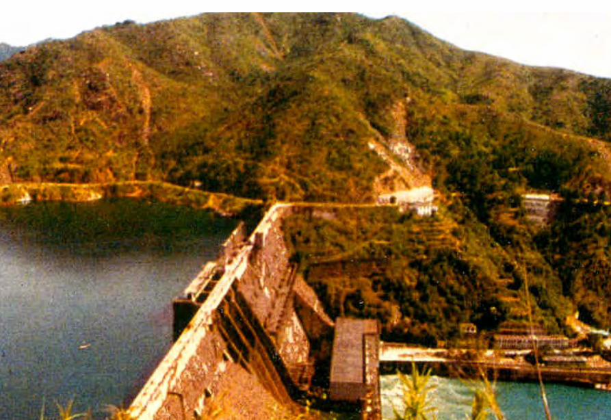
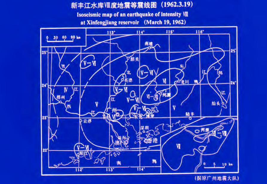
Vaiont Dam
Vaiont Dam
Vaiont Dam
Vaiont Dam
Vaiont Dam
Vaiont Dam
Vaiont Dam
新灘滑坡
新灘滑坡
三峽秭歸千將坪滑坡
三峽巴東滑坡
鏈子崖加固工程
TGP Layout
TGP Layout
TGP Shiplock
TGP Shi l k
TGP Shiplock Section
TGP Shiplock Section
TGP Rock Core
TGP Rock Core
Man Wan Dam
Man Wan Landslide Site
The landslide of the Manwan Hydropower ProjectJanuary 8 1989
云南小湾水电站左岸坝前边坡
开挖时面貌
湖南五強溪水庫滑坡
Da Lake
Xiao Lake
Yinping dam
Rockfallsource
Da Lake
四川大渡河滑坡壩(1933年大地震)
MUDFLOW OF THE LONGYANGXIA POWER STATION
Time of occurrenceAugust 4 of 1997 at 2355
Cause of the incidentA 2-hour constant rainfall with a total precipitation of 55 mm
Source of the mudflow material Natural deposit and construction waste in the Beidagou Gully
龙羊峡水电站128万千瓦
Geotechnical Issues (E) Tunnels and Excavations in Rock
- Fracture-induced instability (rock mass
classification and tunnel support design) - Stress-induced instability - Time-dependent deformation (eg Niagara vs
Three Gorges shiplocks)
Hoover Dam
Hoover Dam
廣州抽水蓄能電站
Two Types of Instability Underground
bull Stress ndash controlledbull Fracture - controlled
Rock Mass Classifications
bull Rock Quality Designation (RQD)
bull Rock Mass Rating System (RMR)
bull Rock Tunnelling Quality Index (Q)
Class Qualitative description BQ Value
I Hard rock intact gt 550
II Hard rock relatively intactRelatively hard rock intact
550 ~ 451
III Hard rock relatively fracturedRelatively hard or interlayered of hard and weak rock relatively
intactRelatively weak rock intact
450 ~ 351
IV Hard rock fracturedRelatively hard rock fractured-relatively fracturedRelatively weak rock or interlayered of weak and hard rock with dominant
weak rock relatively intact or relatively fracturedWeak rock intact or relatively intact
350 ~ 251
V Relatively weak rock fracturedWeak rock fractured-relatively fracturedExtremely weak rock extremely fractured
lt 250
National Standard for Engineering Classification of Rock Masses (GB 50218-94)
Table 1 Basic quality (BQ) of rock mass
BQ = 90 + 3 Rc + 250 Kv
where Rc = uniaxial compressive strength (MPa)Kv = intactness index of rock mass
Table 2 Classification based on uniaxial compressive strength Rc
Rc (MPa) gt 60 60 ~ 30 30 ~ 15 15 ~ 5 lt 5
Description Hard rock Relatively hard rock
Relatively weak rock
Weak rock Extremely weak rock
Table 4 Intactness Factor Kv as a function of Joint Index Jv
Jv (number of joints
m3)
lt 3 3 ~ 10 10 ~ 20 20 ~ 35 gt 35
Kv gt 075 075 ~ 055 055 ~ 035 035 ~ 015 lt 015
Kv =
Vpm= in-situ velocity of longitudinal elastic wave (kms)
Vpr = velocity of longitudinal elastic wave in intact rock (kms)
2
pt
pm
VV
⎟⎟⎠
⎞⎜⎜⎝
⎛
For engineering classification use [BQ] amended for groundwater joint orientation and in-situ stress conditions
[BQ] = BQ ndash 100 (K1 + K2 + K3)
where BQ = basic quality
K1 = correction factor for groundwater
K2 = correction factor for orientation of planes of weakness
K3 = correction factor for in-situ stress conditions
Table 5 K1 values - Correction factor for groundwater conditions
gt450 450 ~ 351 350 ~251 lt250
Wet or drops 0 01 02 ~ 03 04 ~ 06
Shower or flowP lt 01 MPa
Q lt 10 L min m
01 02 ~ 03 04 ~ 06 07 ~ 09
Shower or flowP lt01 MPa
Q lt 10 L min m
02 10
BQK1
Groundwaterinflow
Table 6 K2 values - Correction factor for orientation of planes of weakness
Relation of structure plane to tunnel axis
α lt 30 o= 30 o ~ 75 o
α gt 30 oβ gt 75 o
Other combinations
K2 04 ~ 06 0 ~ 02 02 ~ 04
α - angle between strike of structure plane and tunnel axisβ - dipping angle of structure plane
Table 7 K3 values - Correction factor for in-situ stress conditions
gt 550 550 ~ 351 450 ~ 351 350 ~251 lt 250
Extremely high stress
10 10 10 ~ 15 10 ~ 15 10
High stress 05 05 05 05 ~ 10 05 ~ 10
BQK3
Initialstress state
Technical Specifications for Water Resources and Hydropower ProjectsRock Mass Rating for Tunnelling Projects
Rock class
Rock stability Host rock
rating
StrengthStress S Support type
I Stable long termstability generally no unstable block
100 ~ 85 gt 4 No support or locally bolting or thin shotcreting in case of large span systematic shotcrete bolt and meshII Basically stable no
plasticity deformation85 ~ 65 gt 4
if S lt 4go to III
III Poor stability locally plasticity deformation or collapse
65 ~ 45 gt 2if S lt 2go to IV
Systematic shotcrete bolt and mesh if span = 20 ~ 25 m concrete lining is needed
IV Unstable short self-standing time large scale collapse
45 ~ 25 gt 2if S lt 2go to V
Systematic shotcrete bolt and mesh and concrete lining
V Extremely unstable severe collapse
lt 25 No limits
Host rock rating (HRR) = A + B + C + D + E(somewhat similar to Bieniawskirsquos RMR)
Rating on rock strength (A)
Type of rock materialHard rock Weak rock
Hard rock Moderately hard rock
Relatively weak rock
Weak rock
Uniaxial strength of saturated rock (MPa)
100 ~ 60 60 ~ 30 30 ~ 15 15 ~ 5
Rating (A)Hard rock 30 ~ 20 20 ~ 10
Weak rock 10 ~ 5 5 ~ 0
For uniaxial strength σc gt 100 MPa rock mass rating is 30
Rating on rock intactness (B)
Intactness Intact Relatively intact
Poor intactness
Relatively fractured
Fractured
Intactness factor Kv 10 ~ 075 075 ~ 055 055 ~ 035 035 ~ 015 lt 015
Hard rock 40 ~ 30 30 ~ 22 22 ~ 14 14 ~ 6 lt 6
Weak rock 25 ~ 19 19 ~ 14 14 ~ 9 9 ~ 4 lt 4
Rating (B)
Rating on state of structure planes (C)
Aperture (mm) Filling Roughness evenness Hard rock Relatively weak rock Weak rock
Closed lt 05Undulating rough 27 27 18
Planar smooth 21 21 14
Slight open 05 ~ 50
No filling Undulating rough 24 24 17Undulating smooth or
planar rough21 21 14
Planar smooth 15 15 8
Slacks
Undulating rough 21 21 14
Undulating smooth or planar rough
17 17 11
Planar smooth 12 12 8
Mud
Undulating rough 15 15 10
Undulating smooth or planar rough
12 12 8
Open gt 50
Planar smooth 9 9 6
Slacks 12 12 8Mud 6 6 4
For a length of structure plane which is less than 3 m in hard rock and relatively weak rock rating would increase by 3 for weak rock rating would increase by 2 For length gt 10 m decrease rating by 3 and 2 respectively for hard rock and relatively weak rock If aperture gt 10 m without filling rating is 0
Rating on groundwater condition (D)
Basic rating(A + B + C)
State Wet Drops Linear Flow Flow
Quantity of flow
(Lminm)
lt 25or
lt 10
25-125or
10-100
gt 125or
gt 100
Water head(m)
100-85
Rating on Groundwater Conditions
(D)
0 0 -2 ~ -6
85-65 0 ~ -2 0 ~ -2 -6 ~ -10
65-45 -2 ~ -6 -2 ~ -6 -10 ~ -14
45 ~ 25 -6 ~ -10 -10 ~ -14 -14 ~ -18
lt 25 -10 ~ -14 -14 ~ -18 -18 ~ -20
Rating on orientation of structure planes (E)
Angle betweenstrike of
structure planeand tunnel axis
( o )
90o ~ 60o 60o ~ 30o lt 30o
Dipping angle( o )
gt70 75~45 45~20 lt20 gt70 75~45 45~20 45~20
Crown -2
Wall -5
-5
-2
-12-10-10
0 -2 -5
-5
-10
lt20 gt70 70~45 lt20
0 -2 -12
0
-12-10
-12 0
-5
-2 -5 -10
Rating (E)
Factor Basis for Rating Rating
Saturated Compressive Strength (MPa) gt100 100-60 60-30 30-15 15-5
Rating for A gt30 30-20 20-10 10-5 5-0
Intactness Coefficient 10-075 075-055 055-035 035-015 lt015
σc gt 30 MPa 40-30 30-22 22-14 14-5 lt6
σc lt 30 MPa
Degree of openness
Infillings
Polishness of surface
σc gt 60 MPa
σc 60 - 30 MPa 27-21 24-15 21-12 15-9 12-6
18-14 17-8 14-8 10-6 8-4
gt10m
-3
-2
100-85
σc lt 30 MPa
70o- 45o 45o- 20o lt20o
-5 -10
0-2
-2
-5
σc gt 60 MPa
σc lt 60 MPa
Seeping dripping 0
Linear flow 0 rarr -2
-2 rarr -6
90o - 60o
gt70o
Roof 0
Sidewall -2
Gush of water
25-19 19-14 14-9 9-4 lt4
Closed lt05mm
Slightly open 05 ndash 50 mm Open gt 5 mm
Nil Rock fragments
Clay Fragmented Clay
Flat polished to curved rough
27-21 24-15 21-12 15-9 12-6
Length of structural surface lt3 m 3-10 m
+3 0
+2 0
A + B + C1 + C2 Rating 85-65 64-45 45-25 lt25
0 rarr -2 -2 rarr -6 -6 rarr -10 -10 rarr -14
-2 rarr -6 -6 rarr -10 -10 rarr -14 -14 rarr -18
-6 rarr -10 -10 rarr -14 -14 rarr -18 -18 rarr -20
Angle between tunnel alignment and structural orientation (strike)
60o - 30o lt 30o
Dip of structural orientation gt 70o 70o - 4 5o 45o - 20o lt 20o gt 70o 70o - 45o 45o - 20o lt 20o
2 -5 -10 -12 -5 -10 -12 -12
-5 -10 -2 0 -10 -12 -5 0
Rating for E
E
Rating for D
D
Rating for C2
C2
Rating for C1
Structural surface condition
C1
Rating for B
B
A
Host Rock Rating (HRR)
Recommended rock parameters
Class Gravity density γ(kNm3)
Friction angle ϕ (o)
Cohesion C(MPa)
Deformation module E(MPa)
Poisson ratio ν
I gt 60 gt 21 gt 33 lt 02
II 60 ~ 50 21 ~ 15 33 ~ 20 02 ~ 025
III 265 ~ 245 50 ~ 39 15 ~ 07 20 ~ 6 025 ~ 03
IV 245 ~ 225 39 ~ 27 07 ~ 02 6 ~ 13 03 ~ 035
V lt 225 lt 27 lt 02 lt 13 gt 035
gt 265
Recommended rock strength parameters
ClassConcrete-rock contact Rock mass Deformation
modulus
fprime cprime (MPa) fprime cprime (MPa) E0 X 104 (MPa)
I 15 ~ 13 15 ~ 13 16 ~ 14 25 ~ 20 gt 20
II 13 ~ 11 13 ~ 11 14 ~ 12 20 ~ 15 20 ~ 10
III 11 ~ 09 11 ~ 07 12 ~ 08 15 ~ 07 10 ~ 05
IV 09 ~ 07 07 ~ 03 08 ~ 055 07 ~ 03 05 ~ 02
V 07 ~ 04 03 ~ 005 055 ~ 040 03 ~ 005 02 ~ 002
fprime cprime - Shear strength
Design Applications of HRR
Rock PropertiesRock Type
Rock Mass Stability Host Rock
Rating (HRR)
Strength vs Stress Ratio (S) f C (MPa) E(x 104MPa)
Support Requirements
I Stable with long-term stability no unstable blocks in general
100 - 85 16 - 14 25 - 20 gt 20 Unsupported or localized boltsshotcrete or thin shotcrete add wire mesh for tunnels with large span
II Essentially stable with overall stability no plastic deformation localized rockfall
85 - 65 Downgrade to III for S lt 4
14 - 12 20 - 15 20 - 10
III Poor stability localized plastic deformation cave-in if unsupported temporarily stable in intact relatively soft rock
65 - 45 Downgrade to IV for S lt 2
12 - 08 15 - 07 10 - 05 Bolts and shotcrete with wire mesh concrete lining for tunnel span of 20 -25 m
IV Unstable very short standup time relatively large deformationfailure may occur
45 - 25 Downgrade to V for S lt 1
08 - 055 07 - 03 05 - 02 Bolts and shotcrete with re-bar mesh and concrete lining
V Very unstable could not stand up severe deformationfailure
lt 25 055 - 040 03 - 005 02 - 002
SUPPORT PARAMETERS(National Standard for Design of Bolt-shotcrete Support)
Span (m)Rock Class
B lt 5 m 5 lt B lt 10 10 lt B lt 20 15 lt B lt 20 20 lt B lt 25 m
I No support Shotcrete50 mm
(1) Shotcrete 80-100 mm(2) Shotcrete 50 mmbolt 20-25 m
Shotcrete Shotcrete 120-150 mmwith mesh bolt 30-40 m
II Shotcrete50 mm
(1) Shotcrete 80-100 mm(2) Shotcrete 50 mmbolt 15-2m
(1) Shotcrete 120-150 mm mesh if necessary(2) Shotcrete 80-120 mmbolt 2-3 m mesh if necessary
Shotcrete 120-150 mmmesh bolt 25-30 m
Shotcrete 150-200 mmmesh bolt 3-4 m
III (1) Shotcrete 80-100 mm(2) Shotcrete 50 mmbolt 15-2 m
(1) Shotcrete 120-150 mm mesh if necessary(2) Shotcrete 80-120 mmbolt 2-3 m mesh if necessary
Shotcrete 100-150 mmmesh bolt 20-30 m
Shotcrete 150-200 mmmesh bolt 3-4 m
IV Shotcrete 80-100 mmbolt 15-20 m
Shotcrete 100-200 mmmesh bolt 20-25 m bottom arch if necessary
Shotcrete 150-200 mmmesh bolt 25-30 m bottom arch if necessary
V Shotcrete 120-150 mmmesh bolt 15-20 m bottom arch if necessary
Shotcrete 150-200 mmmesh bolt 20-30 m bottom frame if necessary
GB-J86-85 (Revised)
Comparison of Rock Mass Classification Systems
System Range of Classes
Main Factors
Q 001-1000
9 RQD Jn (joint set number) Jr (joint roughness number) Ja (joint alteration number) Stress reduction factor SRF
RMR 0-100 5 Rock strength RQD Spacing conditions and orientation of joints Groundwater
HRR 0-100 5 Rock strength Intactness Conditions and Orientation of Weakness Planes Groundwater Initial Stresses
BQ lt 250-gt 500
5 Rock strength Intactness Groundwater Orientation of Weakness Planes Initial Stresses
Important Factors that are common among the various systems
1 Rock strength
2 Intactness
3 Condition of planes of weakness
4 Groundwater
5 Orientation of discontinuities
6 Initial stresses
Support systems for underground excavations in ChinaRock Class Span (m) Shotcrete Steel Mesh Bolt Concrete Lining
Total Number
of Projects
Thickness (cm)
Diameters(mm)
Spacing (m)
Diameter (mm)
Length (m)
Spacing (m)
Thickness(cm)
Number of Works
I 5-10 3-15 no no 18-22 12-30 Random no 9
10-15 3-20 6-12 025-15 18-22 15-35 10-15 no 9
15-20 10-20 no no 20-22 10-30 10-15 no 3
II 5-10 5-15 6-10 02-13 16-20 12-21 10-12 no 2 10
10-15 4-20 6-18 02-13 18-22 15-35 08-15 30-50 13
15-20 8-16 8-12 02-13 16-32 20-40 12-15 no 10
III 5-10 5-20 6-10 02-10 18-22 16-30 10-15 wall 1 12
10-15 5-20 5-12 02-10 16-24 15-35 10-15 11
15-20 10-16 6-12 02-08 16-30 20-40 08-12 8
IV 5-10 15-20 6-14 02-025 18-22 18-40 075-125 40 4 10
10-15 5-20 6-12 02-03 16-22 25-40 08-125 50 2 5
15-20 20 10-19 025 22 20 12 1
V 5-10 10-15 8-14 02-025 16-22 15-36 08-12 40 2
4
7
10-15 18-20 6-12 02-03 20-22 25-35 08-10 60 4
Three Gorges ProjectAmended [BQ] Values for Granite
Maximum [BQ]max = 630
Minimum [BQ]min = 500
Average [BQ]mean = 565
Class I- to II+
Guangzhou Pumped Storage Project
bull Location north of Guangzhou Guangdong Province
bull Underground Powerhouse
1465 m x 22 m x 445 m (L x W x H)
at 330 - 400 m depth completed in 1993
bull Host Rock Biotite granite
bull Support System Bolts (at 2 x 15 m spacing)+ 15 cm shotcrete in both crown and
sidewalls
Xiaolangdi Project
bull Location on Yellow River Henan Provincebull Underground Powerhouse
2515 m x 262 m x 614m (L x W x H)At 70 ndash 100 m depth completed in 1999
bull Host Rock Sandstone with argillaceous bedsbull Support System Bolts (at 15 spacing) with wiremesh
and shotcret (20 cm) in crownBolts (at 15 spacing) in sidewallsAnchors locally where required
Xiaolangdi Project on Yellow RiverProposed support parameters in design stage
Support DesignCavern Type Location Rock Type
Rock Grade Tensile Bolt Re Shotcrete
Top T14 III Φ 25 15 X 15 m (mortar bolt)
L = 53 m (alternatively)Φ 6 20 X 20 cmδ = 10 cm (C20)
Tailrace Cavern
Top T14 III Φ 28 15 X 15 m
L = 84 m (alternatively)Φ 8 20 X 20 cmδ = 20 cm (C20)
Sidewall T14
T13-2
III Φ 25 15 X 15 mL = 128 m (alternatively)
Φ 8 20 X 20 cmδ = 15 cm (C20)
Top T14 II- Φ 25 15 X 15 m
L = 73 m (alternatively)Φ 6 20 X 20 cmδ = 15 cm (C20)
Sidewall T14 II- Φ 25 15 X 15 m
L = 53 m (alternatively)Φ 6 20 X 20 cmδ = 10 cm (C20)
Sidewall T14 III Φ 25 15 X 15 m (mortar bolt)
L = 4 mΦ 6 25 X 25 cmδ = 10 cm (C20)
Transformer Cavern
Main Power-house
T14 thick to massive siliceous fine-grained sandstone
T13-2 thick to massive argillaceous and calcareous silty fine-grained sandstone
Xiaolangdi Project on Yellow RiverActual support used at construction stage
Support DesignCavern Type Location Rock Type
Rock Grade Tensile Bolt Re Shotcrete
Support Pres
(MPa)0112
0056
0104
0104
056
0044
Top T14 III Φ 32 3 X 3 m L = 5 m P = 150 KN
Φ 32 3 X 3 m L = 3 m P = 150 KNΦ 6 25 X 25 cmδ = 15 cm (C20)
Tailrace Cavern
Top T14 III Φ 32 3 X 3 m L = 8 m P = 150 KN
Φ 32 3 X 3 m L = 6 m P = 150 KNCable L = 25 m 45 X 6 m P = 1500 KN
Φ 8 20 X 20 cmδ = 20 cm (C20)
Sidewall T14
T13-2
III Φ 32 3 X 3 m L = 10 m P = 150 KNΦ 32 3 X 3 m L = 6 m P = 150 KNTwo rows of pre-stressed bolt added for argillized interlayers 500 KN L = 15 m
Φ 8 20 X 20 cmδ = 20 cm (C20)
Top T14 II- Φ 32 24 X 24 m L = 8 m P = 150 KN
Φ 32 24 X 24 m L = 4 m P = 150 KNΦ 6 20 X 20 cmδ = 20 cm (C20)
Sidewall T14 II- Φ 32 24 X 24 m L = 6 m P = 150 KN
Φ 32 24 X 24 m L = 4 m P = 150 KNΦ 6 25 X 25 cmδ = 15 cm (C20)
Sidewall T14 III Φ 32 15 X 15 m
L = 4 m P = 100 KNΦ 6 25 X 25 cmδ = 10 cm (C20)
Transformer Cavern
Main Power-house
Er Tan Dam
Er Tan Dam
Er Tan Dam Layout
Er Tan Dam Layout
Er Tan Under Construction
Er Tan Under Construction
Er Tan Underground Power House
Er Tan Underground Power House
Er Tan Diversion Tunnel
Er Tan Diversion Tunnel
Er Tan Rock Discing
Er Tan Rock Discing
Er Tan Geostress
Er Tan Geostress(kgcm2)
Strain Energy Approach to Modelling Rock Squeeze Problems
For a virtual displacement δ e
Work Done = Force x Displacement = Feδ e = (δ e)TFe
where Fe = corresponding nodal force Strain energy recovered from unit volume of rock = Stress x Strain = σ ε = ε Tσ = ([B] δ e)T ([D]ε ) = (δ e)T[B][D] ε Work Done = Strain Energy Released (δ e)TFe = (δ e)T int vol [B]T[D] ε dv
or Fe = int vol [B]T[D] ε dv
Some Features of Chinese Hydro Projects
bull Same design framework as in the Westbull Very detailed site investigationsbull Including numerous aditsbull Sometimes leads to significant cost savingsbull (eg Ertan dam allowed to be founded on Class III
rock instead of Class II as called for by Design Standard
bull Strong emphasis on geology and rock mass structure studies
bull Very detailed analysis including numerical modelling AI etc
青海龍羊峽
青海 黃河 李家峽 拱壩壩址
青海 李家峽
探洞
滑面
滑面
李家峽水庫 老滑坡體
剖面
電力需求增長
水電資源
Schematic Map of Hydropower Stations of 1GW and above in Operation or Under Construction
Jin Sha River Hydro Power
南水北調三線
Method of Generation Pros Cons
Capital Construction Cost
(Ratio) Fuel Cost
Fossil
bull Short construction period (2-3 years)
bull Easy to start up
bull Air pollution bull Ashsludge
disposal 1 Relatively high
Hydraulic
bull Longer construction period (gt 5 years)
bull Resettlement of affected population
bull Preservation of cultural amp historic relics
2
Nuclear
bull Relatively long construction period (ge 10 years)
bull Nuclear safety concern
bull Nuclear waste disposal needs
5 Relatively low
Other generation methods solar wind biomass etc
The Joy of being a Hydro Project Engineer
bull Free helicopter jet rides(safe most of the time)
bull Exotic places with breathtaking scenerysceneryand colorful folklore(no tourists around no phone calls etc)
攔路酒(四川 涼山)
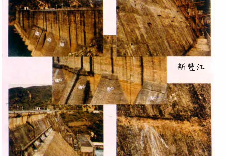
Vaiont Dam
Vaiont Dam
Vaiont Dam
Vaiont Dam
Vaiont Dam
Vaiont Dam
新灘滑坡
新灘滑坡
三峽秭歸千將坪滑坡
三峽巴東滑坡
鏈子崖加固工程
TGP Layout
TGP Layout
TGP Shiplock
TGP Shi l k
TGP Shiplock Section
TGP Shiplock Section
TGP Rock Core
TGP Rock Core
Man Wan Dam
Man Wan Landslide Site
The landslide of the Manwan Hydropower ProjectJanuary 8 1989
云南小湾水电站左岸坝前边坡
开挖时面貌
湖南五強溪水庫滑坡
Da Lake
Xiao Lake
Yinping dam
Rockfallsource
Da Lake
四川大渡河滑坡壩(1933年大地震)
MUDFLOW OF THE LONGYANGXIA POWER STATION
Time of occurrenceAugust 4 of 1997 at 2355
Cause of the incidentA 2-hour constant rainfall with a total precipitation of 55 mm
Source of the mudflow material Natural deposit and construction waste in the Beidagou Gully
龙羊峡水电站128万千瓦
Geotechnical Issues (E) Tunnels and Excavations in Rock
- Fracture-induced instability (rock mass
classification and tunnel support design) - Stress-induced instability - Time-dependent deformation (eg Niagara vs
Three Gorges shiplocks)
Hoover Dam
Hoover Dam
廣州抽水蓄能電站
Two Types of Instability Underground
bull Stress ndash controlledbull Fracture - controlled
Rock Mass Classifications
bull Rock Quality Designation (RQD)
bull Rock Mass Rating System (RMR)
bull Rock Tunnelling Quality Index (Q)
Class Qualitative description BQ Value
I Hard rock intact gt 550
II Hard rock relatively intactRelatively hard rock intact
550 ~ 451
III Hard rock relatively fracturedRelatively hard or interlayered of hard and weak rock relatively
intactRelatively weak rock intact
450 ~ 351
IV Hard rock fracturedRelatively hard rock fractured-relatively fracturedRelatively weak rock or interlayered of weak and hard rock with dominant
weak rock relatively intact or relatively fracturedWeak rock intact or relatively intact
350 ~ 251
V Relatively weak rock fracturedWeak rock fractured-relatively fracturedExtremely weak rock extremely fractured
lt 250
National Standard for Engineering Classification of Rock Masses (GB 50218-94)
Table 1 Basic quality (BQ) of rock mass
BQ = 90 + 3 Rc + 250 Kv
where Rc = uniaxial compressive strength (MPa)Kv = intactness index of rock mass
Table 2 Classification based on uniaxial compressive strength Rc
Rc (MPa) gt 60 60 ~ 30 30 ~ 15 15 ~ 5 lt 5
Description Hard rock Relatively hard rock
Relatively weak rock
Weak rock Extremely weak rock
Table 4 Intactness Factor Kv as a function of Joint Index Jv
Jv (number of joints
m3)
lt 3 3 ~ 10 10 ~ 20 20 ~ 35 gt 35
Kv gt 075 075 ~ 055 055 ~ 035 035 ~ 015 lt 015
Kv =
Vpm= in-situ velocity of longitudinal elastic wave (kms)
Vpr = velocity of longitudinal elastic wave in intact rock (kms)
2
pt
pm
VV
⎟⎟⎠
⎞⎜⎜⎝
⎛
For engineering classification use [BQ] amended for groundwater joint orientation and in-situ stress conditions
[BQ] = BQ ndash 100 (K1 + K2 + K3)
where BQ = basic quality
K1 = correction factor for groundwater
K2 = correction factor for orientation of planes of weakness
K3 = correction factor for in-situ stress conditions
Table 5 K1 values - Correction factor for groundwater conditions
gt450 450 ~ 351 350 ~251 lt250
Wet or drops 0 01 02 ~ 03 04 ~ 06
Shower or flowP lt 01 MPa
Q lt 10 L min m
01 02 ~ 03 04 ~ 06 07 ~ 09
Shower or flowP lt01 MPa
Q lt 10 L min m
02 10
BQK1
Groundwaterinflow
Table 6 K2 values - Correction factor for orientation of planes of weakness
Relation of structure plane to tunnel axis
α lt 30 o= 30 o ~ 75 o
α gt 30 oβ gt 75 o
Other combinations
K2 04 ~ 06 0 ~ 02 02 ~ 04
α - angle between strike of structure plane and tunnel axisβ - dipping angle of structure plane
Table 7 K3 values - Correction factor for in-situ stress conditions
gt 550 550 ~ 351 450 ~ 351 350 ~251 lt 250
Extremely high stress
10 10 10 ~ 15 10 ~ 15 10
High stress 05 05 05 05 ~ 10 05 ~ 10
BQK3
Initialstress state
Technical Specifications for Water Resources and Hydropower ProjectsRock Mass Rating for Tunnelling Projects
Rock class
Rock stability Host rock
rating
StrengthStress S Support type
I Stable long termstability generally no unstable block
100 ~ 85 gt 4 No support or locally bolting or thin shotcreting in case of large span systematic shotcrete bolt and meshII Basically stable no
plasticity deformation85 ~ 65 gt 4
if S lt 4go to III
III Poor stability locally plasticity deformation or collapse
65 ~ 45 gt 2if S lt 2go to IV
Systematic shotcrete bolt and mesh if span = 20 ~ 25 m concrete lining is needed
IV Unstable short self-standing time large scale collapse
45 ~ 25 gt 2if S lt 2go to V
Systematic shotcrete bolt and mesh and concrete lining
V Extremely unstable severe collapse
lt 25 No limits
Host rock rating (HRR) = A + B + C + D + E(somewhat similar to Bieniawskirsquos RMR)
Rating on rock strength (A)
Type of rock materialHard rock Weak rock
Hard rock Moderately hard rock
Relatively weak rock
Weak rock
Uniaxial strength of saturated rock (MPa)
100 ~ 60 60 ~ 30 30 ~ 15 15 ~ 5
Rating (A)Hard rock 30 ~ 20 20 ~ 10
Weak rock 10 ~ 5 5 ~ 0
For uniaxial strength σc gt 100 MPa rock mass rating is 30
Rating on rock intactness (B)
Intactness Intact Relatively intact
Poor intactness
Relatively fractured
Fractured
Intactness factor Kv 10 ~ 075 075 ~ 055 055 ~ 035 035 ~ 015 lt 015
Hard rock 40 ~ 30 30 ~ 22 22 ~ 14 14 ~ 6 lt 6
Weak rock 25 ~ 19 19 ~ 14 14 ~ 9 9 ~ 4 lt 4
Rating (B)
Rating on state of structure planes (C)
Aperture (mm) Filling Roughness evenness Hard rock Relatively weak rock Weak rock
Closed lt 05Undulating rough 27 27 18
Planar smooth 21 21 14
Slight open 05 ~ 50
No filling Undulating rough 24 24 17Undulating smooth or
planar rough21 21 14
Planar smooth 15 15 8
Slacks
Undulating rough 21 21 14
Undulating smooth or planar rough
17 17 11
Planar smooth 12 12 8
Mud
Undulating rough 15 15 10
Undulating smooth or planar rough
12 12 8
Open gt 50
Planar smooth 9 9 6
Slacks 12 12 8Mud 6 6 4
For a length of structure plane which is less than 3 m in hard rock and relatively weak rock rating would increase by 3 for weak rock rating would increase by 2 For length gt 10 m decrease rating by 3 and 2 respectively for hard rock and relatively weak rock If aperture gt 10 m without filling rating is 0
Rating on groundwater condition (D)
Basic rating(A + B + C)
State Wet Drops Linear Flow Flow
Quantity of flow
(Lminm)
lt 25or
lt 10
25-125or
10-100
gt 125or
gt 100
Water head(m)
100-85
Rating on Groundwater Conditions
(D)
0 0 -2 ~ -6
85-65 0 ~ -2 0 ~ -2 -6 ~ -10
65-45 -2 ~ -6 -2 ~ -6 -10 ~ -14
45 ~ 25 -6 ~ -10 -10 ~ -14 -14 ~ -18
lt 25 -10 ~ -14 -14 ~ -18 -18 ~ -20
Rating on orientation of structure planes (E)
Angle betweenstrike of
structure planeand tunnel axis
( o )
90o ~ 60o 60o ~ 30o lt 30o
Dipping angle( o )
gt70 75~45 45~20 lt20 gt70 75~45 45~20 45~20
Crown -2
Wall -5
-5
-2
-12-10-10
0 -2 -5
-5
-10
lt20 gt70 70~45 lt20
0 -2 -12
0
-12-10
-12 0
-5
-2 -5 -10
Rating (E)
Factor Basis for Rating Rating
Saturated Compressive Strength (MPa) gt100 100-60 60-30 30-15 15-5
Rating for A gt30 30-20 20-10 10-5 5-0
Intactness Coefficient 10-075 075-055 055-035 035-015 lt015
σc gt 30 MPa 40-30 30-22 22-14 14-5 lt6
σc lt 30 MPa
Degree of openness
Infillings
Polishness of surface
σc gt 60 MPa
σc 60 - 30 MPa 27-21 24-15 21-12 15-9 12-6
18-14 17-8 14-8 10-6 8-4
gt10m
-3
-2
100-85
σc lt 30 MPa
70o- 45o 45o- 20o lt20o
-5 -10
0-2
-2
-5
σc gt 60 MPa
σc lt 60 MPa
Seeping dripping 0
Linear flow 0 rarr -2
-2 rarr -6
90o - 60o
gt70o
Roof 0
Sidewall -2
Gush of water
25-19 19-14 14-9 9-4 lt4
Closed lt05mm
Slightly open 05 ndash 50 mm Open gt 5 mm
Nil Rock fragments
Clay Fragmented Clay
Flat polished to curved rough
27-21 24-15 21-12 15-9 12-6
Length of structural surface lt3 m 3-10 m
+3 0
+2 0
A + B + C1 + C2 Rating 85-65 64-45 45-25 lt25
0 rarr -2 -2 rarr -6 -6 rarr -10 -10 rarr -14
-2 rarr -6 -6 rarr -10 -10 rarr -14 -14 rarr -18
-6 rarr -10 -10 rarr -14 -14 rarr -18 -18 rarr -20
Angle between tunnel alignment and structural orientation (strike)
60o - 30o lt 30o
Dip of structural orientation gt 70o 70o - 4 5o 45o - 20o lt 20o gt 70o 70o - 45o 45o - 20o lt 20o
2 -5 -10 -12 -5 -10 -12 -12
-5 -10 -2 0 -10 -12 -5 0
Rating for E
E
Rating for D
D
Rating for C2
C2
Rating for C1
Structural surface condition
C1
Rating for B
B
A
Host Rock Rating (HRR)
Recommended rock parameters
Class Gravity density γ(kNm3)
Friction angle ϕ (o)
Cohesion C(MPa)
Deformation module E(MPa)
Poisson ratio ν
I gt 60 gt 21 gt 33 lt 02
II 60 ~ 50 21 ~ 15 33 ~ 20 02 ~ 025
III 265 ~ 245 50 ~ 39 15 ~ 07 20 ~ 6 025 ~ 03
IV 245 ~ 225 39 ~ 27 07 ~ 02 6 ~ 13 03 ~ 035
V lt 225 lt 27 lt 02 lt 13 gt 035
gt 265
Recommended rock strength parameters
ClassConcrete-rock contact Rock mass Deformation
modulus
fprime cprime (MPa) fprime cprime (MPa) E0 X 104 (MPa)
I 15 ~ 13 15 ~ 13 16 ~ 14 25 ~ 20 gt 20
II 13 ~ 11 13 ~ 11 14 ~ 12 20 ~ 15 20 ~ 10
III 11 ~ 09 11 ~ 07 12 ~ 08 15 ~ 07 10 ~ 05
IV 09 ~ 07 07 ~ 03 08 ~ 055 07 ~ 03 05 ~ 02
V 07 ~ 04 03 ~ 005 055 ~ 040 03 ~ 005 02 ~ 002
fprime cprime - Shear strength
Design Applications of HRR
Rock PropertiesRock Type
Rock Mass Stability Host Rock
Rating (HRR)
Strength vs Stress Ratio (S) f C (MPa) E(x 104MPa)
Support Requirements
I Stable with long-term stability no unstable blocks in general
100 - 85 16 - 14 25 - 20 gt 20 Unsupported or localized boltsshotcrete or thin shotcrete add wire mesh for tunnels with large span
II Essentially stable with overall stability no plastic deformation localized rockfall
85 - 65 Downgrade to III for S lt 4
14 - 12 20 - 15 20 - 10
III Poor stability localized plastic deformation cave-in if unsupported temporarily stable in intact relatively soft rock
65 - 45 Downgrade to IV for S lt 2
12 - 08 15 - 07 10 - 05 Bolts and shotcrete with wire mesh concrete lining for tunnel span of 20 -25 m
IV Unstable very short standup time relatively large deformationfailure may occur
45 - 25 Downgrade to V for S lt 1
08 - 055 07 - 03 05 - 02 Bolts and shotcrete with re-bar mesh and concrete lining
V Very unstable could not stand up severe deformationfailure
lt 25 055 - 040 03 - 005 02 - 002
SUPPORT PARAMETERS(National Standard for Design of Bolt-shotcrete Support)
Span (m)Rock Class
B lt 5 m 5 lt B lt 10 10 lt B lt 20 15 lt B lt 20 20 lt B lt 25 m
I No support Shotcrete50 mm
(1) Shotcrete 80-100 mm(2) Shotcrete 50 mmbolt 20-25 m
Shotcrete Shotcrete 120-150 mmwith mesh bolt 30-40 m
II Shotcrete50 mm
(1) Shotcrete 80-100 mm(2) Shotcrete 50 mmbolt 15-2m
(1) Shotcrete 120-150 mm mesh if necessary(2) Shotcrete 80-120 mmbolt 2-3 m mesh if necessary
Shotcrete 120-150 mmmesh bolt 25-30 m
Shotcrete 150-200 mmmesh bolt 3-4 m
III (1) Shotcrete 80-100 mm(2) Shotcrete 50 mmbolt 15-2 m
(1) Shotcrete 120-150 mm mesh if necessary(2) Shotcrete 80-120 mmbolt 2-3 m mesh if necessary
Shotcrete 100-150 mmmesh bolt 20-30 m
Shotcrete 150-200 mmmesh bolt 3-4 m
IV Shotcrete 80-100 mmbolt 15-20 m
Shotcrete 100-200 mmmesh bolt 20-25 m bottom arch if necessary
Shotcrete 150-200 mmmesh bolt 25-30 m bottom arch if necessary
V Shotcrete 120-150 mmmesh bolt 15-20 m bottom arch if necessary
Shotcrete 150-200 mmmesh bolt 20-30 m bottom frame if necessary
GB-J86-85 (Revised)
Comparison of Rock Mass Classification Systems
System Range of Classes
Main Factors
Q 001-1000
9 RQD Jn (joint set number) Jr (joint roughness number) Ja (joint alteration number) Stress reduction factor SRF
RMR 0-100 5 Rock strength RQD Spacing conditions and orientation of joints Groundwater
HRR 0-100 5 Rock strength Intactness Conditions and Orientation of Weakness Planes Groundwater Initial Stresses
BQ lt 250-gt 500
5 Rock strength Intactness Groundwater Orientation of Weakness Planes Initial Stresses
Important Factors that are common among the various systems
1 Rock strength
2 Intactness
3 Condition of planes of weakness
4 Groundwater
5 Orientation of discontinuities
6 Initial stresses
Support systems for underground excavations in ChinaRock Class Span (m) Shotcrete Steel Mesh Bolt Concrete Lining
Total Number
of Projects
Thickness (cm)
Diameters(mm)
Spacing (m)
Diameter (mm)
Length (m)
Spacing (m)
Thickness(cm)
Number of Works
I 5-10 3-15 no no 18-22 12-30 Random no 9
10-15 3-20 6-12 025-15 18-22 15-35 10-15 no 9
15-20 10-20 no no 20-22 10-30 10-15 no 3
II 5-10 5-15 6-10 02-13 16-20 12-21 10-12 no 2 10
10-15 4-20 6-18 02-13 18-22 15-35 08-15 30-50 13
15-20 8-16 8-12 02-13 16-32 20-40 12-15 no 10
III 5-10 5-20 6-10 02-10 18-22 16-30 10-15 wall 1 12
10-15 5-20 5-12 02-10 16-24 15-35 10-15 11
15-20 10-16 6-12 02-08 16-30 20-40 08-12 8
IV 5-10 15-20 6-14 02-025 18-22 18-40 075-125 40 4 10
10-15 5-20 6-12 02-03 16-22 25-40 08-125 50 2 5
15-20 20 10-19 025 22 20 12 1
V 5-10 10-15 8-14 02-025 16-22 15-36 08-12 40 2
4
7
10-15 18-20 6-12 02-03 20-22 25-35 08-10 60 4
Three Gorges ProjectAmended [BQ] Values for Granite
Maximum [BQ]max = 630
Minimum [BQ]min = 500
Average [BQ]mean = 565
Class I- to II+
Guangzhou Pumped Storage Project
bull Location north of Guangzhou Guangdong Province
bull Underground Powerhouse
1465 m x 22 m x 445 m (L x W x H)
at 330 - 400 m depth completed in 1993
bull Host Rock Biotite granite
bull Support System Bolts (at 2 x 15 m spacing)+ 15 cm shotcrete in both crown and
sidewalls
Xiaolangdi Project
bull Location on Yellow River Henan Provincebull Underground Powerhouse
2515 m x 262 m x 614m (L x W x H)At 70 ndash 100 m depth completed in 1999
bull Host Rock Sandstone with argillaceous bedsbull Support System Bolts (at 15 spacing) with wiremesh
and shotcret (20 cm) in crownBolts (at 15 spacing) in sidewallsAnchors locally where required
Xiaolangdi Project on Yellow RiverProposed support parameters in design stage
Support DesignCavern Type Location Rock Type
Rock Grade Tensile Bolt Re Shotcrete
Top T14 III Φ 25 15 X 15 m (mortar bolt)
L = 53 m (alternatively)Φ 6 20 X 20 cmδ = 10 cm (C20)
Tailrace Cavern
Top T14 III Φ 28 15 X 15 m
L = 84 m (alternatively)Φ 8 20 X 20 cmδ = 20 cm (C20)
Sidewall T14
T13-2
III Φ 25 15 X 15 mL = 128 m (alternatively)
Φ 8 20 X 20 cmδ = 15 cm (C20)
Top T14 II- Φ 25 15 X 15 m
L = 73 m (alternatively)Φ 6 20 X 20 cmδ = 15 cm (C20)
Sidewall T14 II- Φ 25 15 X 15 m
L = 53 m (alternatively)Φ 6 20 X 20 cmδ = 10 cm (C20)
Sidewall T14 III Φ 25 15 X 15 m (mortar bolt)
L = 4 mΦ 6 25 X 25 cmδ = 10 cm (C20)
Transformer Cavern
Main Power-house
T14 thick to massive siliceous fine-grained sandstone
T13-2 thick to massive argillaceous and calcareous silty fine-grained sandstone
Xiaolangdi Project on Yellow RiverActual support used at construction stage
Support DesignCavern Type Location Rock Type
Rock Grade Tensile Bolt Re Shotcrete
Support Pres
(MPa)0112
0056
0104
0104
056
0044
Top T14 III Φ 32 3 X 3 m L = 5 m P = 150 KN
Φ 32 3 X 3 m L = 3 m P = 150 KNΦ 6 25 X 25 cmδ = 15 cm (C20)
Tailrace Cavern
Top T14 III Φ 32 3 X 3 m L = 8 m P = 150 KN
Φ 32 3 X 3 m L = 6 m P = 150 KNCable L = 25 m 45 X 6 m P = 1500 KN
Φ 8 20 X 20 cmδ = 20 cm (C20)
Sidewall T14
T13-2
III Φ 32 3 X 3 m L = 10 m P = 150 KNΦ 32 3 X 3 m L = 6 m P = 150 KNTwo rows of pre-stressed bolt added for argillized interlayers 500 KN L = 15 m
Φ 8 20 X 20 cmδ = 20 cm (C20)
Top T14 II- Φ 32 24 X 24 m L = 8 m P = 150 KN
Φ 32 24 X 24 m L = 4 m P = 150 KNΦ 6 20 X 20 cmδ = 20 cm (C20)
Sidewall T14 II- Φ 32 24 X 24 m L = 6 m P = 150 KN
Φ 32 24 X 24 m L = 4 m P = 150 KNΦ 6 25 X 25 cmδ = 15 cm (C20)
Sidewall T14 III Φ 32 15 X 15 m
L = 4 m P = 100 KNΦ 6 25 X 25 cmδ = 10 cm (C20)
Transformer Cavern
Main Power-house
Er Tan Dam
Er Tan Dam
Er Tan Dam Layout
Er Tan Dam Layout
Er Tan Under Construction
Er Tan Under Construction
Er Tan Underground Power House
Er Tan Underground Power House
Er Tan Diversion Tunnel
Er Tan Diversion Tunnel
Er Tan Rock Discing
Er Tan Rock Discing
Er Tan Geostress
Er Tan Geostress(kgcm2)
Strain Energy Approach to Modelling Rock Squeeze Problems
For a virtual displacement δ e
Work Done = Force x Displacement = Feδ e = (δ e)TFe
where Fe = corresponding nodal force Strain energy recovered from unit volume of rock = Stress x Strain = σ ε = ε Tσ = ([B] δ e)T ([D]ε ) = (δ e)T[B][D] ε Work Done = Strain Energy Released (δ e)TFe = (δ e)T int vol [B]T[D] ε dv
or Fe = int vol [B]T[D] ε dv
Some Features of Chinese Hydro Projects
bull Same design framework as in the Westbull Very detailed site investigationsbull Including numerous aditsbull Sometimes leads to significant cost savingsbull (eg Ertan dam allowed to be founded on Class III
rock instead of Class II as called for by Design Standard
bull Strong emphasis on geology and rock mass structure studies
bull Very detailed analysis including numerical modelling AI etc
青海龍羊峽
青海 黃河 李家峽 拱壩壩址
青海 李家峽
探洞
滑面
滑面
李家峽水庫 老滑坡體
剖面
電力需求增長
水電資源
Schematic Map of Hydropower Stations of 1GW and above in Operation or Under Construction
Jin Sha River Hydro Power
南水北調三線
Method of Generation Pros Cons
Capital Construction Cost
(Ratio) Fuel Cost
Fossil
bull Short construction period (2-3 years)
bull Easy to start up
bull Air pollution bull Ashsludge
disposal 1 Relatively high
Hydraulic
bull Longer construction period (gt 5 years)
bull Resettlement of affected population
bull Preservation of cultural amp historic relics
2
Nuclear
bull Relatively long construction period (ge 10 years)
bull Nuclear safety concern
bull Nuclear waste disposal needs
5 Relatively low
Other generation methods solar wind biomass etc
The Joy of being a Hydro Project Engineer
bull Free helicopter jet rides(safe most of the time)
bull Exotic places with breathtaking scenerysceneryand colorful folklore(no tourists around no phone calls etc)
攔路酒(四川 涼山)
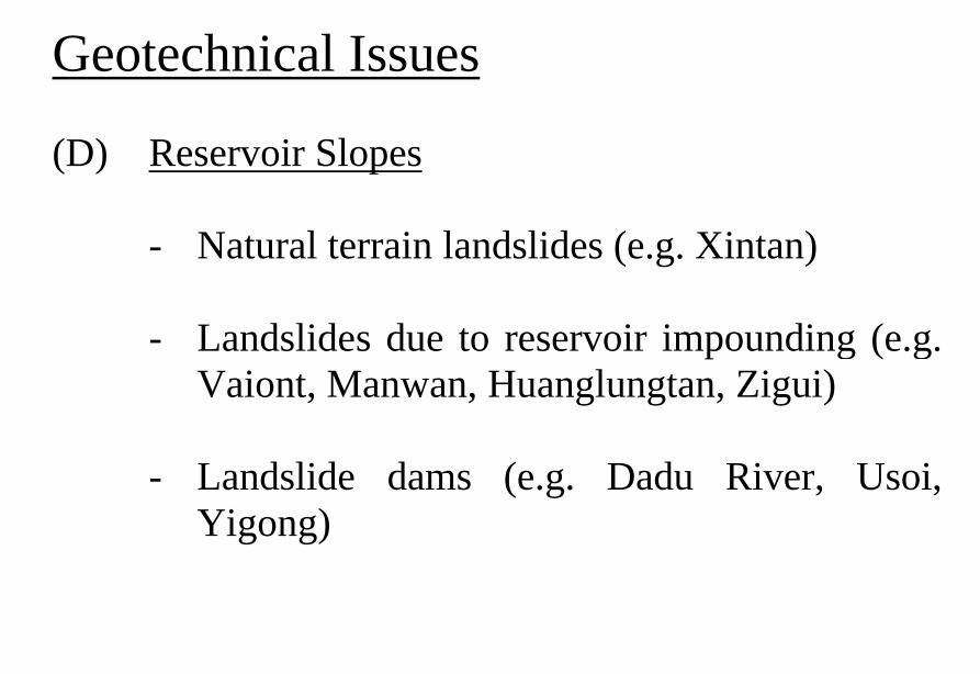
Vaiont Dam
Vaiont Dam
Vaiont Dam
Vaiont Dam
Vaiont Dam
新灘滑坡
新灘滑坡
三峽秭歸千將坪滑坡
三峽巴東滑坡
鏈子崖加固工程
TGP Layout
TGP Layout
TGP Shiplock
TGP Shi l k
TGP Shiplock Section
TGP Shiplock Section
TGP Rock Core
TGP Rock Core
Man Wan Dam
Man Wan Landslide Site
The landslide of the Manwan Hydropower ProjectJanuary 8 1989
云南小湾水电站左岸坝前边坡
开挖时面貌
湖南五強溪水庫滑坡
Da Lake
Xiao Lake
Yinping dam
Rockfallsource
Da Lake
四川大渡河滑坡壩(1933年大地震)
MUDFLOW OF THE LONGYANGXIA POWER STATION
Time of occurrenceAugust 4 of 1997 at 2355
Cause of the incidentA 2-hour constant rainfall with a total precipitation of 55 mm
Source of the mudflow material Natural deposit and construction waste in the Beidagou Gully
龙羊峡水电站128万千瓦
Geotechnical Issues (E) Tunnels and Excavations in Rock
- Fracture-induced instability (rock mass
classification and tunnel support design) - Stress-induced instability - Time-dependent deformation (eg Niagara vs
Three Gorges shiplocks)
Hoover Dam
Hoover Dam
廣州抽水蓄能電站
Two Types of Instability Underground
bull Stress ndash controlledbull Fracture - controlled
Rock Mass Classifications
bull Rock Quality Designation (RQD)
bull Rock Mass Rating System (RMR)
bull Rock Tunnelling Quality Index (Q)
Class Qualitative description BQ Value
I Hard rock intact gt 550
II Hard rock relatively intactRelatively hard rock intact
550 ~ 451
III Hard rock relatively fracturedRelatively hard or interlayered of hard and weak rock relatively
intactRelatively weak rock intact
450 ~ 351
IV Hard rock fracturedRelatively hard rock fractured-relatively fracturedRelatively weak rock or interlayered of weak and hard rock with dominant
weak rock relatively intact or relatively fracturedWeak rock intact or relatively intact
350 ~ 251
V Relatively weak rock fracturedWeak rock fractured-relatively fracturedExtremely weak rock extremely fractured
lt 250
National Standard for Engineering Classification of Rock Masses (GB 50218-94)
Table 1 Basic quality (BQ) of rock mass
BQ = 90 + 3 Rc + 250 Kv
where Rc = uniaxial compressive strength (MPa)Kv = intactness index of rock mass
Table 2 Classification based on uniaxial compressive strength Rc
Rc (MPa) gt 60 60 ~ 30 30 ~ 15 15 ~ 5 lt 5
Description Hard rock Relatively hard rock
Relatively weak rock
Weak rock Extremely weak rock
Table 4 Intactness Factor Kv as a function of Joint Index Jv
Jv (number of joints
m3)
lt 3 3 ~ 10 10 ~ 20 20 ~ 35 gt 35
Kv gt 075 075 ~ 055 055 ~ 035 035 ~ 015 lt 015
Kv =
Vpm= in-situ velocity of longitudinal elastic wave (kms)
Vpr = velocity of longitudinal elastic wave in intact rock (kms)
2
pt
pm
VV
⎟⎟⎠
⎞⎜⎜⎝
⎛
For engineering classification use [BQ] amended for groundwater joint orientation and in-situ stress conditions
[BQ] = BQ ndash 100 (K1 + K2 + K3)
where BQ = basic quality
K1 = correction factor for groundwater
K2 = correction factor for orientation of planes of weakness
K3 = correction factor for in-situ stress conditions
Table 5 K1 values - Correction factor for groundwater conditions
gt450 450 ~ 351 350 ~251 lt250
Wet or drops 0 01 02 ~ 03 04 ~ 06
Shower or flowP lt 01 MPa
Q lt 10 L min m
01 02 ~ 03 04 ~ 06 07 ~ 09
Shower or flowP lt01 MPa
Q lt 10 L min m
02 10
BQK1
Groundwaterinflow
Table 6 K2 values - Correction factor for orientation of planes of weakness
Relation of structure plane to tunnel axis
α lt 30 o= 30 o ~ 75 o
α gt 30 oβ gt 75 o
Other combinations
K2 04 ~ 06 0 ~ 02 02 ~ 04
α - angle between strike of structure plane and tunnel axisβ - dipping angle of structure plane
Table 7 K3 values - Correction factor for in-situ stress conditions
gt 550 550 ~ 351 450 ~ 351 350 ~251 lt 250
Extremely high stress
10 10 10 ~ 15 10 ~ 15 10
High stress 05 05 05 05 ~ 10 05 ~ 10
BQK3
Initialstress state
Technical Specifications for Water Resources and Hydropower ProjectsRock Mass Rating for Tunnelling Projects
Rock class
Rock stability Host rock
rating
StrengthStress S Support type
I Stable long termstability generally no unstable block
100 ~ 85 gt 4 No support or locally bolting or thin shotcreting in case of large span systematic shotcrete bolt and meshII Basically stable no
plasticity deformation85 ~ 65 gt 4
if S lt 4go to III
III Poor stability locally plasticity deformation or collapse
65 ~ 45 gt 2if S lt 2go to IV
Systematic shotcrete bolt and mesh if span = 20 ~ 25 m concrete lining is needed
IV Unstable short self-standing time large scale collapse
45 ~ 25 gt 2if S lt 2go to V
Systematic shotcrete bolt and mesh and concrete lining
V Extremely unstable severe collapse
lt 25 No limits
Host rock rating (HRR) = A + B + C + D + E(somewhat similar to Bieniawskirsquos RMR)
Rating on rock strength (A)
Type of rock materialHard rock Weak rock
Hard rock Moderately hard rock
Relatively weak rock
Weak rock
Uniaxial strength of saturated rock (MPa)
100 ~ 60 60 ~ 30 30 ~ 15 15 ~ 5
Rating (A)Hard rock 30 ~ 20 20 ~ 10
Weak rock 10 ~ 5 5 ~ 0
For uniaxial strength σc gt 100 MPa rock mass rating is 30
Rating on rock intactness (B)
Intactness Intact Relatively intact
Poor intactness
Relatively fractured
Fractured
Intactness factor Kv 10 ~ 075 075 ~ 055 055 ~ 035 035 ~ 015 lt 015
Hard rock 40 ~ 30 30 ~ 22 22 ~ 14 14 ~ 6 lt 6
Weak rock 25 ~ 19 19 ~ 14 14 ~ 9 9 ~ 4 lt 4
Rating (B)
Rating on state of structure planes (C)
Aperture (mm) Filling Roughness evenness Hard rock Relatively weak rock Weak rock
Closed lt 05Undulating rough 27 27 18
Planar smooth 21 21 14
Slight open 05 ~ 50
No filling Undulating rough 24 24 17Undulating smooth or
planar rough21 21 14
Planar smooth 15 15 8
Slacks
Undulating rough 21 21 14
Undulating smooth or planar rough
17 17 11
Planar smooth 12 12 8
Mud
Undulating rough 15 15 10
Undulating smooth or planar rough
12 12 8
Open gt 50
Planar smooth 9 9 6
Slacks 12 12 8Mud 6 6 4
For a length of structure plane which is less than 3 m in hard rock and relatively weak rock rating would increase by 3 for weak rock rating would increase by 2 For length gt 10 m decrease rating by 3 and 2 respectively for hard rock and relatively weak rock If aperture gt 10 m without filling rating is 0
Rating on groundwater condition (D)
Basic rating(A + B + C)
State Wet Drops Linear Flow Flow
Quantity of flow
(Lminm)
lt 25or
lt 10
25-125or
10-100
gt 125or
gt 100
Water head(m)
100-85
Rating on Groundwater Conditions
(D)
0 0 -2 ~ -6
85-65 0 ~ -2 0 ~ -2 -6 ~ -10
65-45 -2 ~ -6 -2 ~ -6 -10 ~ -14
45 ~ 25 -6 ~ -10 -10 ~ -14 -14 ~ -18
lt 25 -10 ~ -14 -14 ~ -18 -18 ~ -20
Rating on orientation of structure planes (E)
Angle betweenstrike of
structure planeand tunnel axis
( o )
90o ~ 60o 60o ~ 30o lt 30o
Dipping angle( o )
gt70 75~45 45~20 lt20 gt70 75~45 45~20 45~20
Crown -2
Wall -5
-5
-2
-12-10-10
0 -2 -5
-5
-10
lt20 gt70 70~45 lt20
0 -2 -12
0
-12-10
-12 0
-5
-2 -5 -10
Rating (E)
Factor Basis for Rating Rating
Saturated Compressive Strength (MPa) gt100 100-60 60-30 30-15 15-5
Rating for A gt30 30-20 20-10 10-5 5-0
Intactness Coefficient 10-075 075-055 055-035 035-015 lt015
σc gt 30 MPa 40-30 30-22 22-14 14-5 lt6
σc lt 30 MPa
Degree of openness
Infillings
Polishness of surface
σc gt 60 MPa
σc 60 - 30 MPa 27-21 24-15 21-12 15-9 12-6
18-14 17-8 14-8 10-6 8-4
gt10m
-3
-2
100-85
σc lt 30 MPa
70o- 45o 45o- 20o lt20o
-5 -10
0-2
-2
-5
σc gt 60 MPa
σc lt 60 MPa
Seeping dripping 0
Linear flow 0 rarr -2
-2 rarr -6
90o - 60o
gt70o
Roof 0
Sidewall -2
Gush of water
25-19 19-14 14-9 9-4 lt4
Closed lt05mm
Slightly open 05 ndash 50 mm Open gt 5 mm
Nil Rock fragments
Clay Fragmented Clay
Flat polished to curved rough
27-21 24-15 21-12 15-9 12-6
Length of structural surface lt3 m 3-10 m
+3 0
+2 0
A + B + C1 + C2 Rating 85-65 64-45 45-25 lt25
0 rarr -2 -2 rarr -6 -6 rarr -10 -10 rarr -14
-2 rarr -6 -6 rarr -10 -10 rarr -14 -14 rarr -18
-6 rarr -10 -10 rarr -14 -14 rarr -18 -18 rarr -20
Angle between tunnel alignment and structural orientation (strike)
60o - 30o lt 30o
Dip of structural orientation gt 70o 70o - 4 5o 45o - 20o lt 20o gt 70o 70o - 45o 45o - 20o lt 20o
2 -5 -10 -12 -5 -10 -12 -12
-5 -10 -2 0 -10 -12 -5 0
Rating for E
E
Rating for D
D
Rating for C2
C2
Rating for C1
Structural surface condition
C1
Rating for B
B
A
Host Rock Rating (HRR)
Recommended rock parameters
Class Gravity density γ(kNm3)
Friction angle ϕ (o)
Cohesion C(MPa)
Deformation module E(MPa)
Poisson ratio ν
I gt 60 gt 21 gt 33 lt 02
II 60 ~ 50 21 ~ 15 33 ~ 20 02 ~ 025
III 265 ~ 245 50 ~ 39 15 ~ 07 20 ~ 6 025 ~ 03
IV 245 ~ 225 39 ~ 27 07 ~ 02 6 ~ 13 03 ~ 035
V lt 225 lt 27 lt 02 lt 13 gt 035
gt 265
Recommended rock strength parameters
ClassConcrete-rock contact Rock mass Deformation
modulus
fprime cprime (MPa) fprime cprime (MPa) E0 X 104 (MPa)
I 15 ~ 13 15 ~ 13 16 ~ 14 25 ~ 20 gt 20
II 13 ~ 11 13 ~ 11 14 ~ 12 20 ~ 15 20 ~ 10
III 11 ~ 09 11 ~ 07 12 ~ 08 15 ~ 07 10 ~ 05
IV 09 ~ 07 07 ~ 03 08 ~ 055 07 ~ 03 05 ~ 02
V 07 ~ 04 03 ~ 005 055 ~ 040 03 ~ 005 02 ~ 002
fprime cprime - Shear strength
Design Applications of HRR
Rock PropertiesRock Type
Rock Mass Stability Host Rock
Rating (HRR)
Strength vs Stress Ratio (S) f C (MPa) E(x 104MPa)
Support Requirements
I Stable with long-term stability no unstable blocks in general
100 - 85 16 - 14 25 - 20 gt 20 Unsupported or localized boltsshotcrete or thin shotcrete add wire mesh for tunnels with large span
II Essentially stable with overall stability no plastic deformation localized rockfall
85 - 65 Downgrade to III for S lt 4
14 - 12 20 - 15 20 - 10
III Poor stability localized plastic deformation cave-in if unsupported temporarily stable in intact relatively soft rock
65 - 45 Downgrade to IV for S lt 2
12 - 08 15 - 07 10 - 05 Bolts and shotcrete with wire mesh concrete lining for tunnel span of 20 -25 m
IV Unstable very short standup time relatively large deformationfailure may occur
45 - 25 Downgrade to V for S lt 1
08 - 055 07 - 03 05 - 02 Bolts and shotcrete with re-bar mesh and concrete lining
V Very unstable could not stand up severe deformationfailure
lt 25 055 - 040 03 - 005 02 - 002
SUPPORT PARAMETERS(National Standard for Design of Bolt-shotcrete Support)
Span (m)Rock Class
B lt 5 m 5 lt B lt 10 10 lt B lt 20 15 lt B lt 20 20 lt B lt 25 m
I No support Shotcrete50 mm
(1) Shotcrete 80-100 mm(2) Shotcrete 50 mmbolt 20-25 m
Shotcrete Shotcrete 120-150 mmwith mesh bolt 30-40 m
II Shotcrete50 mm
(1) Shotcrete 80-100 mm(2) Shotcrete 50 mmbolt 15-2m
(1) Shotcrete 120-150 mm mesh if necessary(2) Shotcrete 80-120 mmbolt 2-3 m mesh if necessary
Shotcrete 120-150 mmmesh bolt 25-30 m
Shotcrete 150-200 mmmesh bolt 3-4 m
III (1) Shotcrete 80-100 mm(2) Shotcrete 50 mmbolt 15-2 m
(1) Shotcrete 120-150 mm mesh if necessary(2) Shotcrete 80-120 mmbolt 2-3 m mesh if necessary
Shotcrete 100-150 mmmesh bolt 20-30 m
Shotcrete 150-200 mmmesh bolt 3-4 m
IV Shotcrete 80-100 mmbolt 15-20 m
Shotcrete 100-200 mmmesh bolt 20-25 m bottom arch if necessary
Shotcrete 150-200 mmmesh bolt 25-30 m bottom arch if necessary
V Shotcrete 120-150 mmmesh bolt 15-20 m bottom arch if necessary
Shotcrete 150-200 mmmesh bolt 20-30 m bottom frame if necessary
GB-J86-85 (Revised)
Comparison of Rock Mass Classification Systems
System Range of Classes
Main Factors
Q 001-1000
9 RQD Jn (joint set number) Jr (joint roughness number) Ja (joint alteration number) Stress reduction factor SRF
RMR 0-100 5 Rock strength RQD Spacing conditions and orientation of joints Groundwater
HRR 0-100 5 Rock strength Intactness Conditions and Orientation of Weakness Planes Groundwater Initial Stresses
BQ lt 250-gt 500
5 Rock strength Intactness Groundwater Orientation of Weakness Planes Initial Stresses
Important Factors that are common among the various systems
1 Rock strength
2 Intactness
3 Condition of planes of weakness
4 Groundwater
5 Orientation of discontinuities
6 Initial stresses
Support systems for underground excavations in ChinaRock Class Span (m) Shotcrete Steel Mesh Bolt Concrete Lining
Total Number
of Projects
Thickness (cm)
Diameters(mm)
Spacing (m)
Diameter (mm)
Length (m)
Spacing (m)
Thickness(cm)
Number of Works
I 5-10 3-15 no no 18-22 12-30 Random no 9
10-15 3-20 6-12 025-15 18-22 15-35 10-15 no 9
15-20 10-20 no no 20-22 10-30 10-15 no 3
II 5-10 5-15 6-10 02-13 16-20 12-21 10-12 no 2 10
10-15 4-20 6-18 02-13 18-22 15-35 08-15 30-50 13
15-20 8-16 8-12 02-13 16-32 20-40 12-15 no 10
III 5-10 5-20 6-10 02-10 18-22 16-30 10-15 wall 1 12
10-15 5-20 5-12 02-10 16-24 15-35 10-15 11
15-20 10-16 6-12 02-08 16-30 20-40 08-12 8
IV 5-10 15-20 6-14 02-025 18-22 18-40 075-125 40 4 10
10-15 5-20 6-12 02-03 16-22 25-40 08-125 50 2 5
15-20 20 10-19 025 22 20 12 1
V 5-10 10-15 8-14 02-025 16-22 15-36 08-12 40 2
4
7
10-15 18-20 6-12 02-03 20-22 25-35 08-10 60 4
Three Gorges ProjectAmended [BQ] Values for Granite
Maximum [BQ]max = 630
Minimum [BQ]min = 500
Average [BQ]mean = 565
Class I- to II+
Guangzhou Pumped Storage Project
bull Location north of Guangzhou Guangdong Province
bull Underground Powerhouse
1465 m x 22 m x 445 m (L x W x H)
at 330 - 400 m depth completed in 1993
bull Host Rock Biotite granite
bull Support System Bolts (at 2 x 15 m spacing)+ 15 cm shotcrete in both crown and
sidewalls
Xiaolangdi Project
bull Location on Yellow River Henan Provincebull Underground Powerhouse
2515 m x 262 m x 614m (L x W x H)At 70 ndash 100 m depth completed in 1999
bull Host Rock Sandstone with argillaceous bedsbull Support System Bolts (at 15 spacing) with wiremesh
and shotcret (20 cm) in crownBolts (at 15 spacing) in sidewallsAnchors locally where required
Xiaolangdi Project on Yellow RiverProposed support parameters in design stage
Support DesignCavern Type Location Rock Type
Rock Grade Tensile Bolt Re Shotcrete
Top T14 III Φ 25 15 X 15 m (mortar bolt)
L = 53 m (alternatively)Φ 6 20 X 20 cmδ = 10 cm (C20)
Tailrace Cavern
Top T14 III Φ 28 15 X 15 m
L = 84 m (alternatively)Φ 8 20 X 20 cmδ = 20 cm (C20)
Sidewall T14
T13-2
III Φ 25 15 X 15 mL = 128 m (alternatively)
Φ 8 20 X 20 cmδ = 15 cm (C20)
Top T14 II- Φ 25 15 X 15 m
L = 73 m (alternatively)Φ 6 20 X 20 cmδ = 15 cm (C20)
Sidewall T14 II- Φ 25 15 X 15 m
L = 53 m (alternatively)Φ 6 20 X 20 cmδ = 10 cm (C20)
Sidewall T14 III Φ 25 15 X 15 m (mortar bolt)
L = 4 mΦ 6 25 X 25 cmδ = 10 cm (C20)
Transformer Cavern
Main Power-house
T14 thick to massive siliceous fine-grained sandstone
T13-2 thick to massive argillaceous and calcareous silty fine-grained sandstone
Xiaolangdi Project on Yellow RiverActual support used at construction stage
Support DesignCavern Type Location Rock Type
Rock Grade Tensile Bolt Re Shotcrete
Support Pres
(MPa)0112
0056
0104
0104
056
0044
Top T14 III Φ 32 3 X 3 m L = 5 m P = 150 KN
Φ 32 3 X 3 m L = 3 m P = 150 KNΦ 6 25 X 25 cmδ = 15 cm (C20)
Tailrace Cavern
Top T14 III Φ 32 3 X 3 m L = 8 m P = 150 KN
Φ 32 3 X 3 m L = 6 m P = 150 KNCable L = 25 m 45 X 6 m P = 1500 KN
Φ 8 20 X 20 cmδ = 20 cm (C20)
Sidewall T14
T13-2
III Φ 32 3 X 3 m L = 10 m P = 150 KNΦ 32 3 X 3 m L = 6 m P = 150 KNTwo rows of pre-stressed bolt added for argillized interlayers 500 KN L = 15 m
Φ 8 20 X 20 cmδ = 20 cm (C20)
Top T14 II- Φ 32 24 X 24 m L = 8 m P = 150 KN
Φ 32 24 X 24 m L = 4 m P = 150 KNΦ 6 20 X 20 cmδ = 20 cm (C20)
Sidewall T14 II- Φ 32 24 X 24 m L = 6 m P = 150 KN
Φ 32 24 X 24 m L = 4 m P = 150 KNΦ 6 25 X 25 cmδ = 15 cm (C20)
Sidewall T14 III Φ 32 15 X 15 m
L = 4 m P = 100 KNΦ 6 25 X 25 cmδ = 10 cm (C20)
Transformer Cavern
Main Power-house
Er Tan Dam
Er Tan Dam
Er Tan Dam Layout
Er Tan Dam Layout
Er Tan Under Construction
Er Tan Under Construction
Er Tan Underground Power House
Er Tan Underground Power House
Er Tan Diversion Tunnel
Er Tan Diversion Tunnel
Er Tan Rock Discing
Er Tan Rock Discing
Er Tan Geostress
Er Tan Geostress(kgcm2)
Strain Energy Approach to Modelling Rock Squeeze Problems
For a virtual displacement δ e
Work Done = Force x Displacement = Feδ e = (δ e)TFe
where Fe = corresponding nodal force Strain energy recovered from unit volume of rock = Stress x Strain = σ ε = ε Tσ = ([B] δ e)T ([D]ε ) = (δ e)T[B][D] ε Work Done = Strain Energy Released (δ e)TFe = (δ e)T int vol [B]T[D] ε dv
or Fe = int vol [B]T[D] ε dv
Some Features of Chinese Hydro Projects
bull Same design framework as in the Westbull Very detailed site investigationsbull Including numerous aditsbull Sometimes leads to significant cost savingsbull (eg Ertan dam allowed to be founded on Class III
rock instead of Class II as called for by Design Standard
bull Strong emphasis on geology and rock mass structure studies
bull Very detailed analysis including numerical modelling AI etc
青海龍羊峽
青海 黃河 李家峽 拱壩壩址
青海 李家峽
探洞
滑面
滑面
李家峽水庫 老滑坡體
剖面
電力需求增長
水電資源
Schematic Map of Hydropower Stations of 1GW and above in Operation or Under Construction
Jin Sha River Hydro Power
南水北調三線
Method of Generation Pros Cons
Capital Construction Cost
(Ratio) Fuel Cost
Fossil
bull Short construction period (2-3 years)
bull Easy to start up
bull Air pollution bull Ashsludge
disposal 1 Relatively high
Hydraulic
bull Longer construction period (gt 5 years)
bull Resettlement of affected population
bull Preservation of cultural amp historic relics
2
Nuclear
bull Relatively long construction period (ge 10 years)
bull Nuclear safety concern
bull Nuclear waste disposal needs
5 Relatively low
Other generation methods solar wind biomass etc
The Joy of being a Hydro Project Engineer
bull Free helicopter jet rides(safe most of the time)
bull Exotic places with breathtaking scenerysceneryand colorful folklore(no tourists around no phone calls etc)
攔路酒(四川 涼山)
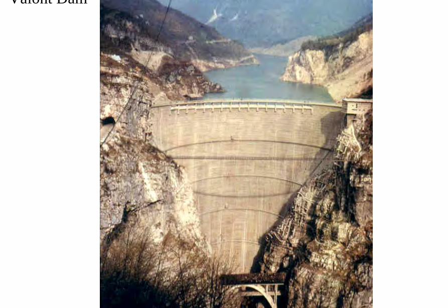
Vaiont Dam
Vaiont Dam
Vaiont Dam
Vaiont Dam
新灘滑坡
新灘滑坡
三峽秭歸千將坪滑坡
三峽巴東滑坡
鏈子崖加固工程
TGP Layout
TGP Layout
TGP Shiplock
TGP Shi l k
TGP Shiplock Section
TGP Shiplock Section
TGP Rock Core
TGP Rock Core
Man Wan Dam
Man Wan Landslide Site
The landslide of the Manwan Hydropower ProjectJanuary 8 1989
云南小湾水电站左岸坝前边坡
开挖时面貌
湖南五強溪水庫滑坡
Da Lake
Xiao Lake
Yinping dam
Rockfallsource
Da Lake
四川大渡河滑坡壩(1933年大地震)
MUDFLOW OF THE LONGYANGXIA POWER STATION
Time of occurrenceAugust 4 of 1997 at 2355
Cause of the incidentA 2-hour constant rainfall with a total precipitation of 55 mm
Source of the mudflow material Natural deposit and construction waste in the Beidagou Gully
龙羊峡水电站128万千瓦
Geotechnical Issues (E) Tunnels and Excavations in Rock
- Fracture-induced instability (rock mass
classification and tunnel support design) - Stress-induced instability - Time-dependent deformation (eg Niagara vs
Three Gorges shiplocks)
Hoover Dam
Hoover Dam
廣州抽水蓄能電站
Two Types of Instability Underground
bull Stress ndash controlledbull Fracture - controlled
Rock Mass Classifications
bull Rock Quality Designation (RQD)
bull Rock Mass Rating System (RMR)
bull Rock Tunnelling Quality Index (Q)
Class Qualitative description BQ Value
I Hard rock intact gt 550
II Hard rock relatively intactRelatively hard rock intact
550 ~ 451
III Hard rock relatively fracturedRelatively hard or interlayered of hard and weak rock relatively
intactRelatively weak rock intact
450 ~ 351
IV Hard rock fracturedRelatively hard rock fractured-relatively fracturedRelatively weak rock or interlayered of weak and hard rock with dominant
weak rock relatively intact or relatively fracturedWeak rock intact or relatively intact
350 ~ 251
V Relatively weak rock fracturedWeak rock fractured-relatively fracturedExtremely weak rock extremely fractured
lt 250
National Standard for Engineering Classification of Rock Masses (GB 50218-94)
Table 1 Basic quality (BQ) of rock mass
BQ = 90 + 3 Rc + 250 Kv
where Rc = uniaxial compressive strength (MPa)Kv = intactness index of rock mass
Table 2 Classification based on uniaxial compressive strength Rc
Rc (MPa) gt 60 60 ~ 30 30 ~ 15 15 ~ 5 lt 5
Description Hard rock Relatively hard rock
Relatively weak rock
Weak rock Extremely weak rock
Table 4 Intactness Factor Kv as a function of Joint Index Jv
Jv (number of joints
m3)
lt 3 3 ~ 10 10 ~ 20 20 ~ 35 gt 35
Kv gt 075 075 ~ 055 055 ~ 035 035 ~ 015 lt 015
Kv =
Vpm= in-situ velocity of longitudinal elastic wave (kms)
Vpr = velocity of longitudinal elastic wave in intact rock (kms)
2
pt
pm
VV
⎟⎟⎠
⎞⎜⎜⎝
⎛
For engineering classification use [BQ] amended for groundwater joint orientation and in-situ stress conditions
[BQ] = BQ ndash 100 (K1 + K2 + K3)
where BQ = basic quality
K1 = correction factor for groundwater
K2 = correction factor for orientation of planes of weakness
K3 = correction factor for in-situ stress conditions
Table 5 K1 values - Correction factor for groundwater conditions
gt450 450 ~ 351 350 ~251 lt250
Wet or drops 0 01 02 ~ 03 04 ~ 06
Shower or flowP lt 01 MPa
Q lt 10 L min m
01 02 ~ 03 04 ~ 06 07 ~ 09
Shower or flowP lt01 MPa
Q lt 10 L min m
02 10
BQK1
Groundwaterinflow
Table 6 K2 values - Correction factor for orientation of planes of weakness
Relation of structure plane to tunnel axis
α lt 30 o= 30 o ~ 75 o
α gt 30 oβ gt 75 o
Other combinations
K2 04 ~ 06 0 ~ 02 02 ~ 04
α - angle between strike of structure plane and tunnel axisβ - dipping angle of structure plane
Table 7 K3 values - Correction factor for in-situ stress conditions
gt 550 550 ~ 351 450 ~ 351 350 ~251 lt 250
Extremely high stress
10 10 10 ~ 15 10 ~ 15 10
High stress 05 05 05 05 ~ 10 05 ~ 10
BQK3
Initialstress state
Technical Specifications for Water Resources and Hydropower ProjectsRock Mass Rating for Tunnelling Projects
Rock class
Rock stability Host rock
rating
StrengthStress S Support type
I Stable long termstability generally no unstable block
100 ~ 85 gt 4 No support or locally bolting or thin shotcreting in case of large span systematic shotcrete bolt and meshII Basically stable no
plasticity deformation85 ~ 65 gt 4
if S lt 4go to III
III Poor stability locally plasticity deformation or collapse
65 ~ 45 gt 2if S lt 2go to IV
Systematic shotcrete bolt and mesh if span = 20 ~ 25 m concrete lining is needed
IV Unstable short self-standing time large scale collapse
45 ~ 25 gt 2if S lt 2go to V
Systematic shotcrete bolt and mesh and concrete lining
V Extremely unstable severe collapse
lt 25 No limits
Host rock rating (HRR) = A + B + C + D + E(somewhat similar to Bieniawskirsquos RMR)
Rating on rock strength (A)
Type of rock materialHard rock Weak rock
Hard rock Moderately hard rock
Relatively weak rock
Weak rock
Uniaxial strength of saturated rock (MPa)
100 ~ 60 60 ~ 30 30 ~ 15 15 ~ 5
Rating (A)Hard rock 30 ~ 20 20 ~ 10
Weak rock 10 ~ 5 5 ~ 0
For uniaxial strength σc gt 100 MPa rock mass rating is 30
Rating on rock intactness (B)
Intactness Intact Relatively intact
Poor intactness
Relatively fractured
Fractured
Intactness factor Kv 10 ~ 075 075 ~ 055 055 ~ 035 035 ~ 015 lt 015
Hard rock 40 ~ 30 30 ~ 22 22 ~ 14 14 ~ 6 lt 6
Weak rock 25 ~ 19 19 ~ 14 14 ~ 9 9 ~ 4 lt 4
Rating (B)
Rating on state of structure planes (C)
Aperture (mm) Filling Roughness evenness Hard rock Relatively weak rock Weak rock
Closed lt 05Undulating rough 27 27 18
Planar smooth 21 21 14
Slight open 05 ~ 50
No filling Undulating rough 24 24 17Undulating smooth or
planar rough21 21 14
Planar smooth 15 15 8
Slacks
Undulating rough 21 21 14
Undulating smooth or planar rough
17 17 11
Planar smooth 12 12 8
Mud
Undulating rough 15 15 10
Undulating smooth or planar rough
12 12 8
Open gt 50
Planar smooth 9 9 6
Slacks 12 12 8Mud 6 6 4
For a length of structure plane which is less than 3 m in hard rock and relatively weak rock rating would increase by 3 for weak rock rating would increase by 2 For length gt 10 m decrease rating by 3 and 2 respectively for hard rock and relatively weak rock If aperture gt 10 m without filling rating is 0
Rating on groundwater condition (D)
Basic rating(A + B + C)
State Wet Drops Linear Flow Flow
Quantity of flow
(Lminm)
lt 25or
lt 10
25-125or
10-100
gt 125or
gt 100
Water head(m)
100-85
Rating on Groundwater Conditions
(D)
0 0 -2 ~ -6
85-65 0 ~ -2 0 ~ -2 -6 ~ -10
65-45 -2 ~ -6 -2 ~ -6 -10 ~ -14
45 ~ 25 -6 ~ -10 -10 ~ -14 -14 ~ -18
lt 25 -10 ~ -14 -14 ~ -18 -18 ~ -20
Rating on orientation of structure planes (E)
Angle betweenstrike of
structure planeand tunnel axis
( o )
90o ~ 60o 60o ~ 30o lt 30o
Dipping angle( o )
gt70 75~45 45~20 lt20 gt70 75~45 45~20 45~20
Crown -2
Wall -5
-5
-2
-12-10-10
0 -2 -5
-5
-10
lt20 gt70 70~45 lt20
0 -2 -12
0
-12-10
-12 0
-5
-2 -5 -10
Rating (E)
Factor Basis for Rating Rating
Saturated Compressive Strength (MPa) gt100 100-60 60-30 30-15 15-5
Rating for A gt30 30-20 20-10 10-5 5-0
Intactness Coefficient 10-075 075-055 055-035 035-015 lt015
σc gt 30 MPa 40-30 30-22 22-14 14-5 lt6
σc lt 30 MPa
Degree of openness
Infillings
Polishness of surface
σc gt 60 MPa
σc 60 - 30 MPa 27-21 24-15 21-12 15-9 12-6
18-14 17-8 14-8 10-6 8-4
gt10m
-3
-2
100-85
σc lt 30 MPa
70o- 45o 45o- 20o lt20o
-5 -10
0-2
-2
-5
σc gt 60 MPa
σc lt 60 MPa
Seeping dripping 0
Linear flow 0 rarr -2
-2 rarr -6
90o - 60o
gt70o
Roof 0
Sidewall -2
Gush of water
25-19 19-14 14-9 9-4 lt4
Closed lt05mm
Slightly open 05 ndash 50 mm Open gt 5 mm
Nil Rock fragments
Clay Fragmented Clay
Flat polished to curved rough
27-21 24-15 21-12 15-9 12-6
Length of structural surface lt3 m 3-10 m
+3 0
+2 0
A + B + C1 + C2 Rating 85-65 64-45 45-25 lt25
0 rarr -2 -2 rarr -6 -6 rarr -10 -10 rarr -14
-2 rarr -6 -6 rarr -10 -10 rarr -14 -14 rarr -18
-6 rarr -10 -10 rarr -14 -14 rarr -18 -18 rarr -20
Angle between tunnel alignment and structural orientation (strike)
60o - 30o lt 30o
Dip of structural orientation gt 70o 70o - 4 5o 45o - 20o lt 20o gt 70o 70o - 45o 45o - 20o lt 20o
2 -5 -10 -12 -5 -10 -12 -12
-5 -10 -2 0 -10 -12 -5 0
Rating for E
E
Rating for D
D
Rating for C2
C2
Rating for C1
Structural surface condition
C1
Rating for B
B
A
Host Rock Rating (HRR)
Recommended rock parameters
Class Gravity density γ(kNm3)
Friction angle ϕ (o)
Cohesion C(MPa)
Deformation module E(MPa)
Poisson ratio ν
I gt 60 gt 21 gt 33 lt 02
II 60 ~ 50 21 ~ 15 33 ~ 20 02 ~ 025
III 265 ~ 245 50 ~ 39 15 ~ 07 20 ~ 6 025 ~ 03
IV 245 ~ 225 39 ~ 27 07 ~ 02 6 ~ 13 03 ~ 035
V lt 225 lt 27 lt 02 lt 13 gt 035
gt 265
Recommended rock strength parameters
ClassConcrete-rock contact Rock mass Deformation
modulus
fprime cprime (MPa) fprime cprime (MPa) E0 X 104 (MPa)
I 15 ~ 13 15 ~ 13 16 ~ 14 25 ~ 20 gt 20
II 13 ~ 11 13 ~ 11 14 ~ 12 20 ~ 15 20 ~ 10
III 11 ~ 09 11 ~ 07 12 ~ 08 15 ~ 07 10 ~ 05
IV 09 ~ 07 07 ~ 03 08 ~ 055 07 ~ 03 05 ~ 02
V 07 ~ 04 03 ~ 005 055 ~ 040 03 ~ 005 02 ~ 002
fprime cprime - Shear strength
Design Applications of HRR
Rock PropertiesRock Type
Rock Mass Stability Host Rock
Rating (HRR)
Strength vs Stress Ratio (S) f C (MPa) E(x 104MPa)
Support Requirements
I Stable with long-term stability no unstable blocks in general
100 - 85 16 - 14 25 - 20 gt 20 Unsupported or localized boltsshotcrete or thin shotcrete add wire mesh for tunnels with large span
II Essentially stable with overall stability no plastic deformation localized rockfall
85 - 65 Downgrade to III for S lt 4
14 - 12 20 - 15 20 - 10
III Poor stability localized plastic deformation cave-in if unsupported temporarily stable in intact relatively soft rock
65 - 45 Downgrade to IV for S lt 2
12 - 08 15 - 07 10 - 05 Bolts and shotcrete with wire mesh concrete lining for tunnel span of 20 -25 m
IV Unstable very short standup time relatively large deformationfailure may occur
45 - 25 Downgrade to V for S lt 1
08 - 055 07 - 03 05 - 02 Bolts and shotcrete with re-bar mesh and concrete lining
V Very unstable could not stand up severe deformationfailure
lt 25 055 - 040 03 - 005 02 - 002
SUPPORT PARAMETERS(National Standard for Design of Bolt-shotcrete Support)
Span (m)Rock Class
B lt 5 m 5 lt B lt 10 10 lt B lt 20 15 lt B lt 20 20 lt B lt 25 m
I No support Shotcrete50 mm
(1) Shotcrete 80-100 mm(2) Shotcrete 50 mmbolt 20-25 m
Shotcrete Shotcrete 120-150 mmwith mesh bolt 30-40 m
II Shotcrete50 mm
(1) Shotcrete 80-100 mm(2) Shotcrete 50 mmbolt 15-2m
(1) Shotcrete 120-150 mm mesh if necessary(2) Shotcrete 80-120 mmbolt 2-3 m mesh if necessary
Shotcrete 120-150 mmmesh bolt 25-30 m
Shotcrete 150-200 mmmesh bolt 3-4 m
III (1) Shotcrete 80-100 mm(2) Shotcrete 50 mmbolt 15-2 m
(1) Shotcrete 120-150 mm mesh if necessary(2) Shotcrete 80-120 mmbolt 2-3 m mesh if necessary
Shotcrete 100-150 mmmesh bolt 20-30 m
Shotcrete 150-200 mmmesh bolt 3-4 m
IV Shotcrete 80-100 mmbolt 15-20 m
Shotcrete 100-200 mmmesh bolt 20-25 m bottom arch if necessary
Shotcrete 150-200 mmmesh bolt 25-30 m bottom arch if necessary
V Shotcrete 120-150 mmmesh bolt 15-20 m bottom arch if necessary
Shotcrete 150-200 mmmesh bolt 20-30 m bottom frame if necessary
GB-J86-85 (Revised)
Comparison of Rock Mass Classification Systems
System Range of Classes
Main Factors
Q 001-1000
9 RQD Jn (joint set number) Jr (joint roughness number) Ja (joint alteration number) Stress reduction factor SRF
RMR 0-100 5 Rock strength RQD Spacing conditions and orientation of joints Groundwater
HRR 0-100 5 Rock strength Intactness Conditions and Orientation of Weakness Planes Groundwater Initial Stresses
BQ lt 250-gt 500
5 Rock strength Intactness Groundwater Orientation of Weakness Planes Initial Stresses
Important Factors that are common among the various systems
1 Rock strength
2 Intactness
3 Condition of planes of weakness
4 Groundwater
5 Orientation of discontinuities
6 Initial stresses
Support systems for underground excavations in ChinaRock Class Span (m) Shotcrete Steel Mesh Bolt Concrete Lining
Total Number
of Projects
Thickness (cm)
Diameters(mm)
Spacing (m)
Diameter (mm)
Length (m)
Spacing (m)
Thickness(cm)
Number of Works
I 5-10 3-15 no no 18-22 12-30 Random no 9
10-15 3-20 6-12 025-15 18-22 15-35 10-15 no 9
15-20 10-20 no no 20-22 10-30 10-15 no 3
II 5-10 5-15 6-10 02-13 16-20 12-21 10-12 no 2 10
10-15 4-20 6-18 02-13 18-22 15-35 08-15 30-50 13
15-20 8-16 8-12 02-13 16-32 20-40 12-15 no 10
III 5-10 5-20 6-10 02-10 18-22 16-30 10-15 wall 1 12
10-15 5-20 5-12 02-10 16-24 15-35 10-15 11
15-20 10-16 6-12 02-08 16-30 20-40 08-12 8
IV 5-10 15-20 6-14 02-025 18-22 18-40 075-125 40 4 10
10-15 5-20 6-12 02-03 16-22 25-40 08-125 50 2 5
15-20 20 10-19 025 22 20 12 1
V 5-10 10-15 8-14 02-025 16-22 15-36 08-12 40 2
4
7
10-15 18-20 6-12 02-03 20-22 25-35 08-10 60 4
Three Gorges ProjectAmended [BQ] Values for Granite
Maximum [BQ]max = 630
Minimum [BQ]min = 500
Average [BQ]mean = 565
Class I- to II+
Guangzhou Pumped Storage Project
bull Location north of Guangzhou Guangdong Province
bull Underground Powerhouse
1465 m x 22 m x 445 m (L x W x H)
at 330 - 400 m depth completed in 1993
bull Host Rock Biotite granite
bull Support System Bolts (at 2 x 15 m spacing)+ 15 cm shotcrete in both crown and
sidewalls
Xiaolangdi Project
bull Location on Yellow River Henan Provincebull Underground Powerhouse
2515 m x 262 m x 614m (L x W x H)At 70 ndash 100 m depth completed in 1999
bull Host Rock Sandstone with argillaceous bedsbull Support System Bolts (at 15 spacing) with wiremesh
and shotcret (20 cm) in crownBolts (at 15 spacing) in sidewallsAnchors locally where required
Xiaolangdi Project on Yellow RiverProposed support parameters in design stage
Support DesignCavern Type Location Rock Type
Rock Grade Tensile Bolt Re Shotcrete
Top T14 III Φ 25 15 X 15 m (mortar bolt)
L = 53 m (alternatively)Φ 6 20 X 20 cmδ = 10 cm (C20)
Tailrace Cavern
Top T14 III Φ 28 15 X 15 m
L = 84 m (alternatively)Φ 8 20 X 20 cmδ = 20 cm (C20)
Sidewall T14
T13-2
III Φ 25 15 X 15 mL = 128 m (alternatively)
Φ 8 20 X 20 cmδ = 15 cm (C20)
Top T14 II- Φ 25 15 X 15 m
L = 73 m (alternatively)Φ 6 20 X 20 cmδ = 15 cm (C20)
Sidewall T14 II- Φ 25 15 X 15 m
L = 53 m (alternatively)Φ 6 20 X 20 cmδ = 10 cm (C20)
Sidewall T14 III Φ 25 15 X 15 m (mortar bolt)
L = 4 mΦ 6 25 X 25 cmδ = 10 cm (C20)
Transformer Cavern
Main Power-house
T14 thick to massive siliceous fine-grained sandstone
T13-2 thick to massive argillaceous and calcareous silty fine-grained sandstone
Xiaolangdi Project on Yellow RiverActual support used at construction stage
Support DesignCavern Type Location Rock Type
Rock Grade Tensile Bolt Re Shotcrete
Support Pres
(MPa)0112
0056
0104
0104
056
0044
Top T14 III Φ 32 3 X 3 m L = 5 m P = 150 KN
Φ 32 3 X 3 m L = 3 m P = 150 KNΦ 6 25 X 25 cmδ = 15 cm (C20)
Tailrace Cavern
Top T14 III Φ 32 3 X 3 m L = 8 m P = 150 KN
Φ 32 3 X 3 m L = 6 m P = 150 KNCable L = 25 m 45 X 6 m P = 1500 KN
Φ 8 20 X 20 cmδ = 20 cm (C20)
Sidewall T14
T13-2
III Φ 32 3 X 3 m L = 10 m P = 150 KNΦ 32 3 X 3 m L = 6 m P = 150 KNTwo rows of pre-stressed bolt added for argillized interlayers 500 KN L = 15 m
Φ 8 20 X 20 cmδ = 20 cm (C20)
Top T14 II- Φ 32 24 X 24 m L = 8 m P = 150 KN
Φ 32 24 X 24 m L = 4 m P = 150 KNΦ 6 20 X 20 cmδ = 20 cm (C20)
Sidewall T14 II- Φ 32 24 X 24 m L = 6 m P = 150 KN
Φ 32 24 X 24 m L = 4 m P = 150 KNΦ 6 25 X 25 cmδ = 15 cm (C20)
Sidewall T14 III Φ 32 15 X 15 m
L = 4 m P = 100 KNΦ 6 25 X 25 cmδ = 10 cm (C20)
Transformer Cavern
Main Power-house
Er Tan Dam
Er Tan Dam
Er Tan Dam Layout
Er Tan Dam Layout
Er Tan Under Construction
Er Tan Under Construction
Er Tan Underground Power House
Er Tan Underground Power House
Er Tan Diversion Tunnel
Er Tan Diversion Tunnel
Er Tan Rock Discing
Er Tan Rock Discing
Er Tan Geostress
Er Tan Geostress(kgcm2)
Strain Energy Approach to Modelling Rock Squeeze Problems
For a virtual displacement δ e
Work Done = Force x Displacement = Feδ e = (δ e)TFe
where Fe = corresponding nodal force Strain energy recovered from unit volume of rock = Stress x Strain = σ ε = ε Tσ = ([B] δ e)T ([D]ε ) = (δ e)T[B][D] ε Work Done = Strain Energy Released (δ e)TFe = (δ e)T int vol [B]T[D] ε dv
or Fe = int vol [B]T[D] ε dv
Some Features of Chinese Hydro Projects
bull Same design framework as in the Westbull Very detailed site investigationsbull Including numerous aditsbull Sometimes leads to significant cost savingsbull (eg Ertan dam allowed to be founded on Class III
rock instead of Class II as called for by Design Standard
bull Strong emphasis on geology and rock mass structure studies
bull Very detailed analysis including numerical modelling AI etc
青海龍羊峽
青海 黃河 李家峽 拱壩壩址
青海 李家峽
探洞
滑面
滑面
李家峽水庫 老滑坡體
剖面
電力需求增長
水電資源
Schematic Map of Hydropower Stations of 1GW and above in Operation or Under Construction
Jin Sha River Hydro Power
南水北調三線
Method of Generation Pros Cons
Capital Construction Cost
(Ratio) Fuel Cost
Fossil
bull Short construction period (2-3 years)
bull Easy to start up
bull Air pollution bull Ashsludge
disposal 1 Relatively high
Hydraulic
bull Longer construction period (gt 5 years)
bull Resettlement of affected population
bull Preservation of cultural amp historic relics
2
Nuclear
bull Relatively long construction period (ge 10 years)
bull Nuclear safety concern
bull Nuclear waste disposal needs
5 Relatively low
Other generation methods solar wind biomass etc
The Joy of being a Hydro Project Engineer
bull Free helicopter jet rides(safe most of the time)
bull Exotic places with breathtaking scenerysceneryand colorful folklore(no tourists around no phone calls etc)
攔路酒(四川 涼山)
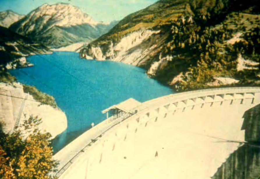
Vaiont Dam
Vaiont Dam
Vaiont Dam
新灘滑坡
新灘滑坡
三峽秭歸千將坪滑坡
三峽巴東滑坡
鏈子崖加固工程
TGP Layout
TGP Layout
TGP Shiplock
TGP Shi l k
TGP Shiplock Section
TGP Shiplock Section
TGP Rock Core
TGP Rock Core
Man Wan Dam
Man Wan Landslide Site
The landslide of the Manwan Hydropower ProjectJanuary 8 1989
云南小湾水电站左岸坝前边坡
开挖时面貌
湖南五強溪水庫滑坡
Da Lake
Xiao Lake
Yinping dam
Rockfallsource
Da Lake
四川大渡河滑坡壩(1933年大地震)
MUDFLOW OF THE LONGYANGXIA POWER STATION
Time of occurrenceAugust 4 of 1997 at 2355
Cause of the incidentA 2-hour constant rainfall with a total precipitation of 55 mm
Source of the mudflow material Natural deposit and construction waste in the Beidagou Gully
龙羊峡水电站128万千瓦
Geotechnical Issues (E) Tunnels and Excavations in Rock
- Fracture-induced instability (rock mass
classification and tunnel support design) - Stress-induced instability - Time-dependent deformation (eg Niagara vs
Three Gorges shiplocks)
Hoover Dam
Hoover Dam
廣州抽水蓄能電站
Two Types of Instability Underground
bull Stress ndash controlledbull Fracture - controlled
Rock Mass Classifications
bull Rock Quality Designation (RQD)
bull Rock Mass Rating System (RMR)
bull Rock Tunnelling Quality Index (Q)
Class Qualitative description BQ Value
I Hard rock intact gt 550
II Hard rock relatively intactRelatively hard rock intact
550 ~ 451
III Hard rock relatively fracturedRelatively hard or interlayered of hard and weak rock relatively
intactRelatively weak rock intact
450 ~ 351
IV Hard rock fracturedRelatively hard rock fractured-relatively fracturedRelatively weak rock or interlayered of weak and hard rock with dominant
weak rock relatively intact or relatively fracturedWeak rock intact or relatively intact
350 ~ 251
V Relatively weak rock fracturedWeak rock fractured-relatively fracturedExtremely weak rock extremely fractured
lt 250
National Standard for Engineering Classification of Rock Masses (GB 50218-94)
Table 1 Basic quality (BQ) of rock mass
BQ = 90 + 3 Rc + 250 Kv
where Rc = uniaxial compressive strength (MPa)Kv = intactness index of rock mass
Table 2 Classification based on uniaxial compressive strength Rc
Rc (MPa) gt 60 60 ~ 30 30 ~ 15 15 ~ 5 lt 5
Description Hard rock Relatively hard rock
Relatively weak rock
Weak rock Extremely weak rock
Table 4 Intactness Factor Kv as a function of Joint Index Jv
Jv (number of joints
m3)
lt 3 3 ~ 10 10 ~ 20 20 ~ 35 gt 35
Kv gt 075 075 ~ 055 055 ~ 035 035 ~ 015 lt 015
Kv =
Vpm= in-situ velocity of longitudinal elastic wave (kms)
Vpr = velocity of longitudinal elastic wave in intact rock (kms)
2
pt
pm
VV
⎟⎟⎠
⎞⎜⎜⎝
⎛
For engineering classification use [BQ] amended for groundwater joint orientation and in-situ stress conditions
[BQ] = BQ ndash 100 (K1 + K2 + K3)
where BQ = basic quality
K1 = correction factor for groundwater
K2 = correction factor for orientation of planes of weakness
K3 = correction factor for in-situ stress conditions
Table 5 K1 values - Correction factor for groundwater conditions
gt450 450 ~ 351 350 ~251 lt250
Wet or drops 0 01 02 ~ 03 04 ~ 06
Shower or flowP lt 01 MPa
Q lt 10 L min m
01 02 ~ 03 04 ~ 06 07 ~ 09
Shower or flowP lt01 MPa
Q lt 10 L min m
02 10
BQK1
Groundwaterinflow
Table 6 K2 values - Correction factor for orientation of planes of weakness
Relation of structure plane to tunnel axis
α lt 30 o= 30 o ~ 75 o
α gt 30 oβ gt 75 o
Other combinations
K2 04 ~ 06 0 ~ 02 02 ~ 04
α - angle between strike of structure plane and tunnel axisβ - dipping angle of structure plane
Table 7 K3 values - Correction factor for in-situ stress conditions
gt 550 550 ~ 351 450 ~ 351 350 ~251 lt 250
Extremely high stress
10 10 10 ~ 15 10 ~ 15 10
High stress 05 05 05 05 ~ 10 05 ~ 10
BQK3
Initialstress state
Technical Specifications for Water Resources and Hydropower ProjectsRock Mass Rating for Tunnelling Projects
Rock class
Rock stability Host rock
rating
StrengthStress S Support type
I Stable long termstability generally no unstable block
100 ~ 85 gt 4 No support or locally bolting or thin shotcreting in case of large span systematic shotcrete bolt and meshII Basically stable no
plasticity deformation85 ~ 65 gt 4
if S lt 4go to III
III Poor stability locally plasticity deformation or collapse
65 ~ 45 gt 2if S lt 2go to IV
Systematic shotcrete bolt and mesh if span = 20 ~ 25 m concrete lining is needed
IV Unstable short self-standing time large scale collapse
45 ~ 25 gt 2if S lt 2go to V
Systematic shotcrete bolt and mesh and concrete lining
V Extremely unstable severe collapse
lt 25 No limits
Host rock rating (HRR) = A + B + C + D + E(somewhat similar to Bieniawskirsquos RMR)
Rating on rock strength (A)
Type of rock materialHard rock Weak rock
Hard rock Moderately hard rock
Relatively weak rock
Weak rock
Uniaxial strength of saturated rock (MPa)
100 ~ 60 60 ~ 30 30 ~ 15 15 ~ 5
Rating (A)Hard rock 30 ~ 20 20 ~ 10
Weak rock 10 ~ 5 5 ~ 0
For uniaxial strength σc gt 100 MPa rock mass rating is 30
Rating on rock intactness (B)
Intactness Intact Relatively intact
Poor intactness
Relatively fractured
Fractured
Intactness factor Kv 10 ~ 075 075 ~ 055 055 ~ 035 035 ~ 015 lt 015
Hard rock 40 ~ 30 30 ~ 22 22 ~ 14 14 ~ 6 lt 6
Weak rock 25 ~ 19 19 ~ 14 14 ~ 9 9 ~ 4 lt 4
Rating (B)
Rating on state of structure planes (C)
Aperture (mm) Filling Roughness evenness Hard rock Relatively weak rock Weak rock
Closed lt 05Undulating rough 27 27 18
Planar smooth 21 21 14
Slight open 05 ~ 50
No filling Undulating rough 24 24 17Undulating smooth or
planar rough21 21 14
Planar smooth 15 15 8
Slacks
Undulating rough 21 21 14
Undulating smooth or planar rough
17 17 11
Planar smooth 12 12 8
Mud
Undulating rough 15 15 10
Undulating smooth or planar rough
12 12 8
Open gt 50
Planar smooth 9 9 6
Slacks 12 12 8Mud 6 6 4
For a length of structure plane which is less than 3 m in hard rock and relatively weak rock rating would increase by 3 for weak rock rating would increase by 2 For length gt 10 m decrease rating by 3 and 2 respectively for hard rock and relatively weak rock If aperture gt 10 m without filling rating is 0
Rating on groundwater condition (D)
Basic rating(A + B + C)
State Wet Drops Linear Flow Flow
Quantity of flow
(Lminm)
lt 25or
lt 10
25-125or
10-100
gt 125or
gt 100
Water head(m)
100-85
Rating on Groundwater Conditions
(D)
0 0 -2 ~ -6
85-65 0 ~ -2 0 ~ -2 -6 ~ -10
65-45 -2 ~ -6 -2 ~ -6 -10 ~ -14
45 ~ 25 -6 ~ -10 -10 ~ -14 -14 ~ -18
lt 25 -10 ~ -14 -14 ~ -18 -18 ~ -20
Rating on orientation of structure planes (E)
Angle betweenstrike of
structure planeand tunnel axis
( o )
90o ~ 60o 60o ~ 30o lt 30o
Dipping angle( o )
gt70 75~45 45~20 lt20 gt70 75~45 45~20 45~20
Crown -2
Wall -5
-5
-2
-12-10-10
0 -2 -5
-5
-10
lt20 gt70 70~45 lt20
0 -2 -12
0
-12-10
-12 0
-5
-2 -5 -10
Rating (E)
Factor Basis for Rating Rating
Saturated Compressive Strength (MPa) gt100 100-60 60-30 30-15 15-5
Rating for A gt30 30-20 20-10 10-5 5-0
Intactness Coefficient 10-075 075-055 055-035 035-015 lt015
σc gt 30 MPa 40-30 30-22 22-14 14-5 lt6
σc lt 30 MPa
Degree of openness
Infillings
Polishness of surface
σc gt 60 MPa
σc 60 - 30 MPa 27-21 24-15 21-12 15-9 12-6
18-14 17-8 14-8 10-6 8-4
gt10m
-3
-2
100-85
σc lt 30 MPa
70o- 45o 45o- 20o lt20o
-5 -10
0-2
-2
-5
σc gt 60 MPa
σc lt 60 MPa
Seeping dripping 0
Linear flow 0 rarr -2
-2 rarr -6
90o - 60o
gt70o
Roof 0
Sidewall -2
Gush of water
25-19 19-14 14-9 9-4 lt4
Closed lt05mm
Slightly open 05 ndash 50 mm Open gt 5 mm
Nil Rock fragments
Clay Fragmented Clay
Flat polished to curved rough
27-21 24-15 21-12 15-9 12-6
Length of structural surface lt3 m 3-10 m
+3 0
+2 0
A + B + C1 + C2 Rating 85-65 64-45 45-25 lt25
0 rarr -2 -2 rarr -6 -6 rarr -10 -10 rarr -14
-2 rarr -6 -6 rarr -10 -10 rarr -14 -14 rarr -18
-6 rarr -10 -10 rarr -14 -14 rarr -18 -18 rarr -20
Angle between tunnel alignment and structural orientation (strike)
60o - 30o lt 30o
Dip of structural orientation gt 70o 70o - 4 5o 45o - 20o lt 20o gt 70o 70o - 45o 45o - 20o lt 20o
2 -5 -10 -12 -5 -10 -12 -12
-5 -10 -2 0 -10 -12 -5 0
Rating for E
E
Rating for D
D
Rating for C2
C2
Rating for C1
Structural surface condition
C1
Rating for B
B
A
Host Rock Rating (HRR)
Recommended rock parameters
Class Gravity density γ(kNm3)
Friction angle ϕ (o)
Cohesion C(MPa)
Deformation module E(MPa)
Poisson ratio ν
I gt 60 gt 21 gt 33 lt 02
II 60 ~ 50 21 ~ 15 33 ~ 20 02 ~ 025
III 265 ~ 245 50 ~ 39 15 ~ 07 20 ~ 6 025 ~ 03
IV 245 ~ 225 39 ~ 27 07 ~ 02 6 ~ 13 03 ~ 035
V lt 225 lt 27 lt 02 lt 13 gt 035
gt 265
Recommended rock strength parameters
ClassConcrete-rock contact Rock mass Deformation
modulus
fprime cprime (MPa) fprime cprime (MPa) E0 X 104 (MPa)
I 15 ~ 13 15 ~ 13 16 ~ 14 25 ~ 20 gt 20
II 13 ~ 11 13 ~ 11 14 ~ 12 20 ~ 15 20 ~ 10
III 11 ~ 09 11 ~ 07 12 ~ 08 15 ~ 07 10 ~ 05
IV 09 ~ 07 07 ~ 03 08 ~ 055 07 ~ 03 05 ~ 02
V 07 ~ 04 03 ~ 005 055 ~ 040 03 ~ 005 02 ~ 002
fprime cprime - Shear strength
Design Applications of HRR
Rock PropertiesRock Type
Rock Mass Stability Host Rock
Rating (HRR)
Strength vs Stress Ratio (S) f C (MPa) E(x 104MPa)
Support Requirements
I Stable with long-term stability no unstable blocks in general
100 - 85 16 - 14 25 - 20 gt 20 Unsupported or localized boltsshotcrete or thin shotcrete add wire mesh for tunnels with large span
II Essentially stable with overall stability no plastic deformation localized rockfall
85 - 65 Downgrade to III for S lt 4
14 - 12 20 - 15 20 - 10
III Poor stability localized plastic deformation cave-in if unsupported temporarily stable in intact relatively soft rock
65 - 45 Downgrade to IV for S lt 2
12 - 08 15 - 07 10 - 05 Bolts and shotcrete with wire mesh concrete lining for tunnel span of 20 -25 m
IV Unstable very short standup time relatively large deformationfailure may occur
45 - 25 Downgrade to V for S lt 1
08 - 055 07 - 03 05 - 02 Bolts and shotcrete with re-bar mesh and concrete lining
V Very unstable could not stand up severe deformationfailure
lt 25 055 - 040 03 - 005 02 - 002
SUPPORT PARAMETERS(National Standard for Design of Bolt-shotcrete Support)
Span (m)Rock Class
B lt 5 m 5 lt B lt 10 10 lt B lt 20 15 lt B lt 20 20 lt B lt 25 m
I No support Shotcrete50 mm
(1) Shotcrete 80-100 mm(2) Shotcrete 50 mmbolt 20-25 m
Shotcrete Shotcrete 120-150 mmwith mesh bolt 30-40 m
II Shotcrete50 mm
(1) Shotcrete 80-100 mm(2) Shotcrete 50 mmbolt 15-2m
(1) Shotcrete 120-150 mm mesh if necessary(2) Shotcrete 80-120 mmbolt 2-3 m mesh if necessary
Shotcrete 120-150 mmmesh bolt 25-30 m
Shotcrete 150-200 mmmesh bolt 3-4 m
III (1) Shotcrete 80-100 mm(2) Shotcrete 50 mmbolt 15-2 m
(1) Shotcrete 120-150 mm mesh if necessary(2) Shotcrete 80-120 mmbolt 2-3 m mesh if necessary
Shotcrete 100-150 mmmesh bolt 20-30 m
Shotcrete 150-200 mmmesh bolt 3-4 m
IV Shotcrete 80-100 mmbolt 15-20 m
Shotcrete 100-200 mmmesh bolt 20-25 m bottom arch if necessary
Shotcrete 150-200 mmmesh bolt 25-30 m bottom arch if necessary
V Shotcrete 120-150 mmmesh bolt 15-20 m bottom arch if necessary
Shotcrete 150-200 mmmesh bolt 20-30 m bottom frame if necessary
GB-J86-85 (Revised)
Comparison of Rock Mass Classification Systems
System Range of Classes
Main Factors
Q 001-1000
9 RQD Jn (joint set number) Jr (joint roughness number) Ja (joint alteration number) Stress reduction factor SRF
RMR 0-100 5 Rock strength RQD Spacing conditions and orientation of joints Groundwater
HRR 0-100 5 Rock strength Intactness Conditions and Orientation of Weakness Planes Groundwater Initial Stresses
BQ lt 250-gt 500
5 Rock strength Intactness Groundwater Orientation of Weakness Planes Initial Stresses
Important Factors that are common among the various systems
1 Rock strength
2 Intactness
3 Condition of planes of weakness
4 Groundwater
5 Orientation of discontinuities
6 Initial stresses
Support systems for underground excavations in ChinaRock Class Span (m) Shotcrete Steel Mesh Bolt Concrete Lining
Total Number
of Projects
Thickness (cm)
Diameters(mm)
Spacing (m)
Diameter (mm)
Length (m)
Spacing (m)
Thickness(cm)
Number of Works
I 5-10 3-15 no no 18-22 12-30 Random no 9
10-15 3-20 6-12 025-15 18-22 15-35 10-15 no 9
15-20 10-20 no no 20-22 10-30 10-15 no 3
II 5-10 5-15 6-10 02-13 16-20 12-21 10-12 no 2 10
10-15 4-20 6-18 02-13 18-22 15-35 08-15 30-50 13
15-20 8-16 8-12 02-13 16-32 20-40 12-15 no 10
III 5-10 5-20 6-10 02-10 18-22 16-30 10-15 wall 1 12
10-15 5-20 5-12 02-10 16-24 15-35 10-15 11
15-20 10-16 6-12 02-08 16-30 20-40 08-12 8
IV 5-10 15-20 6-14 02-025 18-22 18-40 075-125 40 4 10
10-15 5-20 6-12 02-03 16-22 25-40 08-125 50 2 5
15-20 20 10-19 025 22 20 12 1
V 5-10 10-15 8-14 02-025 16-22 15-36 08-12 40 2
4
7
10-15 18-20 6-12 02-03 20-22 25-35 08-10 60 4
Three Gorges ProjectAmended [BQ] Values for Granite
Maximum [BQ]max = 630
Minimum [BQ]min = 500
Average [BQ]mean = 565
Class I- to II+
Guangzhou Pumped Storage Project
bull Location north of Guangzhou Guangdong Province
bull Underground Powerhouse
1465 m x 22 m x 445 m (L x W x H)
at 330 - 400 m depth completed in 1993
bull Host Rock Biotite granite
bull Support System Bolts (at 2 x 15 m spacing)+ 15 cm shotcrete in both crown and
sidewalls
Xiaolangdi Project
bull Location on Yellow River Henan Provincebull Underground Powerhouse
2515 m x 262 m x 614m (L x W x H)At 70 ndash 100 m depth completed in 1999
bull Host Rock Sandstone with argillaceous bedsbull Support System Bolts (at 15 spacing) with wiremesh
and shotcret (20 cm) in crownBolts (at 15 spacing) in sidewallsAnchors locally where required
Xiaolangdi Project on Yellow RiverProposed support parameters in design stage
Support DesignCavern Type Location Rock Type
Rock Grade Tensile Bolt Re Shotcrete
Top T14 III Φ 25 15 X 15 m (mortar bolt)
L = 53 m (alternatively)Φ 6 20 X 20 cmδ = 10 cm (C20)
Tailrace Cavern
Top T14 III Φ 28 15 X 15 m
L = 84 m (alternatively)Φ 8 20 X 20 cmδ = 20 cm (C20)
Sidewall T14
T13-2
III Φ 25 15 X 15 mL = 128 m (alternatively)
Φ 8 20 X 20 cmδ = 15 cm (C20)
Top T14 II- Φ 25 15 X 15 m
L = 73 m (alternatively)Φ 6 20 X 20 cmδ = 15 cm (C20)
Sidewall T14 II- Φ 25 15 X 15 m
L = 53 m (alternatively)Φ 6 20 X 20 cmδ = 10 cm (C20)
Sidewall T14 III Φ 25 15 X 15 m (mortar bolt)
L = 4 mΦ 6 25 X 25 cmδ = 10 cm (C20)
Transformer Cavern
Main Power-house
T14 thick to massive siliceous fine-grained sandstone
T13-2 thick to massive argillaceous and calcareous silty fine-grained sandstone
Xiaolangdi Project on Yellow RiverActual support used at construction stage
Support DesignCavern Type Location Rock Type
Rock Grade Tensile Bolt Re Shotcrete
Support Pres
(MPa)0112
0056
0104
0104
056
0044
Top T14 III Φ 32 3 X 3 m L = 5 m P = 150 KN
Φ 32 3 X 3 m L = 3 m P = 150 KNΦ 6 25 X 25 cmδ = 15 cm (C20)
Tailrace Cavern
Top T14 III Φ 32 3 X 3 m L = 8 m P = 150 KN
Φ 32 3 X 3 m L = 6 m P = 150 KNCable L = 25 m 45 X 6 m P = 1500 KN
Φ 8 20 X 20 cmδ = 20 cm (C20)
Sidewall T14
T13-2
III Φ 32 3 X 3 m L = 10 m P = 150 KNΦ 32 3 X 3 m L = 6 m P = 150 KNTwo rows of pre-stressed bolt added for argillized interlayers 500 KN L = 15 m
Φ 8 20 X 20 cmδ = 20 cm (C20)
Top T14 II- Φ 32 24 X 24 m L = 8 m P = 150 KN
Φ 32 24 X 24 m L = 4 m P = 150 KNΦ 6 20 X 20 cmδ = 20 cm (C20)
Sidewall T14 II- Φ 32 24 X 24 m L = 6 m P = 150 KN
Φ 32 24 X 24 m L = 4 m P = 150 KNΦ 6 25 X 25 cmδ = 15 cm (C20)
Sidewall T14 III Φ 32 15 X 15 m
L = 4 m P = 100 KNΦ 6 25 X 25 cmδ = 10 cm (C20)
Transformer Cavern
Main Power-house
Er Tan Dam
Er Tan Dam
Er Tan Dam Layout
Er Tan Dam Layout
Er Tan Under Construction
Er Tan Under Construction
Er Tan Underground Power House
Er Tan Underground Power House
Er Tan Diversion Tunnel
Er Tan Diversion Tunnel
Er Tan Rock Discing
Er Tan Rock Discing
Er Tan Geostress
Er Tan Geostress(kgcm2)
Strain Energy Approach to Modelling Rock Squeeze Problems
For a virtual displacement δ e
Work Done = Force x Displacement = Feδ e = (δ e)TFe
where Fe = corresponding nodal force Strain energy recovered from unit volume of rock = Stress x Strain = σ ε = ε Tσ = ([B] δ e)T ([D]ε ) = (δ e)T[B][D] ε Work Done = Strain Energy Released (δ e)TFe = (δ e)T int vol [B]T[D] ε dv
or Fe = int vol [B]T[D] ε dv
Some Features of Chinese Hydro Projects
bull Same design framework as in the Westbull Very detailed site investigationsbull Including numerous aditsbull Sometimes leads to significant cost savingsbull (eg Ertan dam allowed to be founded on Class III
rock instead of Class II as called for by Design Standard
bull Strong emphasis on geology and rock mass structure studies
bull Very detailed analysis including numerical modelling AI etc
青海龍羊峽
青海 黃河 李家峽 拱壩壩址
青海 李家峽
探洞
滑面
滑面
李家峽水庫 老滑坡體
剖面
電力需求增長
水電資源
Schematic Map of Hydropower Stations of 1GW and above in Operation or Under Construction
Jin Sha River Hydro Power
南水北調三線
Method of Generation Pros Cons
Capital Construction Cost
(Ratio) Fuel Cost
Fossil
bull Short construction period (2-3 years)
bull Easy to start up
bull Air pollution bull Ashsludge
disposal 1 Relatively high
Hydraulic
bull Longer construction period (gt 5 years)
bull Resettlement of affected population
bull Preservation of cultural amp historic relics
2
Nuclear
bull Relatively long construction period (ge 10 years)
bull Nuclear safety concern
bull Nuclear waste disposal needs
5 Relatively low
Other generation methods solar wind biomass etc
The Joy of being a Hydro Project Engineer
bull Free helicopter jet rides(safe most of the time)
bull Exotic places with breathtaking scenerysceneryand colorful folklore(no tourists around no phone calls etc)
攔路酒(四川 涼山)
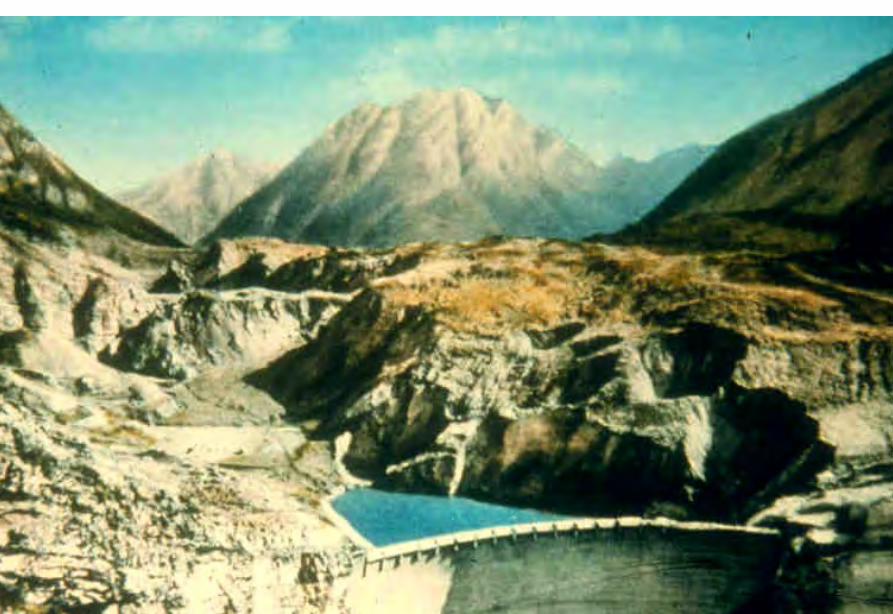
Vaiont Dam
Vaiont Dam
新灘滑坡
新灘滑坡
三峽秭歸千將坪滑坡
三峽巴東滑坡
鏈子崖加固工程
TGP Layout
TGP Layout
TGP Shiplock
TGP Shi l k
TGP Shiplock Section
TGP Shiplock Section
TGP Rock Core
TGP Rock Core
Man Wan Dam
Man Wan Landslide Site
The landslide of the Manwan Hydropower ProjectJanuary 8 1989
云南小湾水电站左岸坝前边坡
开挖时面貌
湖南五強溪水庫滑坡
Da Lake
Xiao Lake
Yinping dam
Rockfallsource
Da Lake
四川大渡河滑坡壩(1933年大地震)
MUDFLOW OF THE LONGYANGXIA POWER STATION
Time of occurrenceAugust 4 of 1997 at 2355
Cause of the incidentA 2-hour constant rainfall with a total precipitation of 55 mm
Source of the mudflow material Natural deposit and construction waste in the Beidagou Gully
龙羊峡水电站128万千瓦
Geotechnical Issues (E) Tunnels and Excavations in Rock
- Fracture-induced instability (rock mass
classification and tunnel support design) - Stress-induced instability - Time-dependent deformation (eg Niagara vs
Three Gorges shiplocks)
Hoover Dam
Hoover Dam
廣州抽水蓄能電站
Two Types of Instability Underground
bull Stress ndash controlledbull Fracture - controlled
Rock Mass Classifications
bull Rock Quality Designation (RQD)
bull Rock Mass Rating System (RMR)
bull Rock Tunnelling Quality Index (Q)
Class Qualitative description BQ Value
I Hard rock intact gt 550
II Hard rock relatively intactRelatively hard rock intact
550 ~ 451
III Hard rock relatively fracturedRelatively hard or interlayered of hard and weak rock relatively
intactRelatively weak rock intact
450 ~ 351
IV Hard rock fracturedRelatively hard rock fractured-relatively fracturedRelatively weak rock or interlayered of weak and hard rock with dominant
weak rock relatively intact or relatively fracturedWeak rock intact or relatively intact
350 ~ 251
V Relatively weak rock fracturedWeak rock fractured-relatively fracturedExtremely weak rock extremely fractured
lt 250
National Standard for Engineering Classification of Rock Masses (GB 50218-94)
Table 1 Basic quality (BQ) of rock mass
BQ = 90 + 3 Rc + 250 Kv
where Rc = uniaxial compressive strength (MPa)Kv = intactness index of rock mass
Table 2 Classification based on uniaxial compressive strength Rc
Rc (MPa) gt 60 60 ~ 30 30 ~ 15 15 ~ 5 lt 5
Description Hard rock Relatively hard rock
Relatively weak rock
Weak rock Extremely weak rock
Table 4 Intactness Factor Kv as a function of Joint Index Jv
Jv (number of joints
m3)
lt 3 3 ~ 10 10 ~ 20 20 ~ 35 gt 35
Kv gt 075 075 ~ 055 055 ~ 035 035 ~ 015 lt 015
Kv =
Vpm= in-situ velocity of longitudinal elastic wave (kms)
Vpr = velocity of longitudinal elastic wave in intact rock (kms)
2
pt
pm
VV
⎟⎟⎠
⎞⎜⎜⎝
⎛
For engineering classification use [BQ] amended for groundwater joint orientation and in-situ stress conditions
[BQ] = BQ ndash 100 (K1 + K2 + K3)
where BQ = basic quality
K1 = correction factor for groundwater
K2 = correction factor for orientation of planes of weakness
K3 = correction factor for in-situ stress conditions
Table 5 K1 values - Correction factor for groundwater conditions
gt450 450 ~ 351 350 ~251 lt250
Wet or drops 0 01 02 ~ 03 04 ~ 06
Shower or flowP lt 01 MPa
Q lt 10 L min m
01 02 ~ 03 04 ~ 06 07 ~ 09
Shower or flowP lt01 MPa
Q lt 10 L min m
02 10
BQK1
Groundwaterinflow
Table 6 K2 values - Correction factor for orientation of planes of weakness
Relation of structure plane to tunnel axis
α lt 30 o= 30 o ~ 75 o
α gt 30 oβ gt 75 o
Other combinations
K2 04 ~ 06 0 ~ 02 02 ~ 04
α - angle between strike of structure plane and tunnel axisβ - dipping angle of structure plane
Table 7 K3 values - Correction factor for in-situ stress conditions
gt 550 550 ~ 351 450 ~ 351 350 ~251 lt 250
Extremely high stress
10 10 10 ~ 15 10 ~ 15 10
High stress 05 05 05 05 ~ 10 05 ~ 10
BQK3
Initialstress state
Technical Specifications for Water Resources and Hydropower ProjectsRock Mass Rating for Tunnelling Projects
Rock class
Rock stability Host rock
rating
StrengthStress S Support type
I Stable long termstability generally no unstable block
100 ~ 85 gt 4 No support or locally bolting or thin shotcreting in case of large span systematic shotcrete bolt and meshII Basically stable no
plasticity deformation85 ~ 65 gt 4
if S lt 4go to III
III Poor stability locally plasticity deformation or collapse
65 ~ 45 gt 2if S lt 2go to IV
Systematic shotcrete bolt and mesh if span = 20 ~ 25 m concrete lining is needed
IV Unstable short self-standing time large scale collapse
45 ~ 25 gt 2if S lt 2go to V
Systematic shotcrete bolt and mesh and concrete lining
V Extremely unstable severe collapse
lt 25 No limits
Host rock rating (HRR) = A + B + C + D + E(somewhat similar to Bieniawskirsquos RMR)
Rating on rock strength (A)
Type of rock materialHard rock Weak rock
Hard rock Moderately hard rock
Relatively weak rock
Weak rock
Uniaxial strength of saturated rock (MPa)
100 ~ 60 60 ~ 30 30 ~ 15 15 ~ 5
Rating (A)Hard rock 30 ~ 20 20 ~ 10
Weak rock 10 ~ 5 5 ~ 0
For uniaxial strength σc gt 100 MPa rock mass rating is 30
Rating on rock intactness (B)
Intactness Intact Relatively intact
Poor intactness
Relatively fractured
Fractured
Intactness factor Kv 10 ~ 075 075 ~ 055 055 ~ 035 035 ~ 015 lt 015
Hard rock 40 ~ 30 30 ~ 22 22 ~ 14 14 ~ 6 lt 6
Weak rock 25 ~ 19 19 ~ 14 14 ~ 9 9 ~ 4 lt 4
Rating (B)
Rating on state of structure planes (C)
Aperture (mm) Filling Roughness evenness Hard rock Relatively weak rock Weak rock
Closed lt 05Undulating rough 27 27 18
Planar smooth 21 21 14
Slight open 05 ~ 50
No filling Undulating rough 24 24 17Undulating smooth or
planar rough21 21 14
Planar smooth 15 15 8
Slacks
Undulating rough 21 21 14
Undulating smooth or planar rough
17 17 11
Planar smooth 12 12 8
Mud
Undulating rough 15 15 10
Undulating smooth or planar rough
12 12 8
Open gt 50
Planar smooth 9 9 6
Slacks 12 12 8Mud 6 6 4
For a length of structure plane which is less than 3 m in hard rock and relatively weak rock rating would increase by 3 for weak rock rating would increase by 2 For length gt 10 m decrease rating by 3 and 2 respectively for hard rock and relatively weak rock If aperture gt 10 m without filling rating is 0
Rating on groundwater condition (D)
Basic rating(A + B + C)
State Wet Drops Linear Flow Flow
Quantity of flow
(Lminm)
lt 25or
lt 10
25-125or
10-100
gt 125or
gt 100
Water head(m)
100-85
Rating on Groundwater Conditions
(D)
0 0 -2 ~ -6
85-65 0 ~ -2 0 ~ -2 -6 ~ -10
65-45 -2 ~ -6 -2 ~ -6 -10 ~ -14
45 ~ 25 -6 ~ -10 -10 ~ -14 -14 ~ -18
lt 25 -10 ~ -14 -14 ~ -18 -18 ~ -20
Rating on orientation of structure planes (E)
Angle betweenstrike of
structure planeand tunnel axis
( o )
90o ~ 60o 60o ~ 30o lt 30o
Dipping angle( o )
gt70 75~45 45~20 lt20 gt70 75~45 45~20 45~20
Crown -2
Wall -5
-5
-2
-12-10-10
0 -2 -5
-5
-10
lt20 gt70 70~45 lt20
0 -2 -12
0
-12-10
-12 0
-5
-2 -5 -10
Rating (E)
Factor Basis for Rating Rating
Saturated Compressive Strength (MPa) gt100 100-60 60-30 30-15 15-5
Rating for A gt30 30-20 20-10 10-5 5-0
Intactness Coefficient 10-075 075-055 055-035 035-015 lt015
σc gt 30 MPa 40-30 30-22 22-14 14-5 lt6
σc lt 30 MPa
Degree of openness
Infillings
Polishness of surface
σc gt 60 MPa
σc 60 - 30 MPa 27-21 24-15 21-12 15-9 12-6
18-14 17-8 14-8 10-6 8-4
gt10m
-3
-2
100-85
σc lt 30 MPa
70o- 45o 45o- 20o lt20o
-5 -10
0-2
-2
-5
σc gt 60 MPa
σc lt 60 MPa
Seeping dripping 0
Linear flow 0 rarr -2
-2 rarr -6
90o - 60o
gt70o
Roof 0
Sidewall -2
Gush of water
25-19 19-14 14-9 9-4 lt4
Closed lt05mm
Slightly open 05 ndash 50 mm Open gt 5 mm
Nil Rock fragments
Clay Fragmented Clay
Flat polished to curved rough
27-21 24-15 21-12 15-9 12-6
Length of structural surface lt3 m 3-10 m
+3 0
+2 0
A + B + C1 + C2 Rating 85-65 64-45 45-25 lt25
0 rarr -2 -2 rarr -6 -6 rarr -10 -10 rarr -14
-2 rarr -6 -6 rarr -10 -10 rarr -14 -14 rarr -18
-6 rarr -10 -10 rarr -14 -14 rarr -18 -18 rarr -20
Angle between tunnel alignment and structural orientation (strike)
60o - 30o lt 30o
Dip of structural orientation gt 70o 70o - 4 5o 45o - 20o lt 20o gt 70o 70o - 45o 45o - 20o lt 20o
2 -5 -10 -12 -5 -10 -12 -12
-5 -10 -2 0 -10 -12 -5 0
Rating for E
E
Rating for D
D
Rating for C2
C2
Rating for C1
Structural surface condition
C1
Rating for B
B
A
Host Rock Rating (HRR)
Recommended rock parameters
Class Gravity density γ(kNm3)
Friction angle ϕ (o)
Cohesion C(MPa)
Deformation module E(MPa)
Poisson ratio ν
I gt 60 gt 21 gt 33 lt 02
II 60 ~ 50 21 ~ 15 33 ~ 20 02 ~ 025
III 265 ~ 245 50 ~ 39 15 ~ 07 20 ~ 6 025 ~ 03
IV 245 ~ 225 39 ~ 27 07 ~ 02 6 ~ 13 03 ~ 035
V lt 225 lt 27 lt 02 lt 13 gt 035
gt 265
Recommended rock strength parameters
ClassConcrete-rock contact Rock mass Deformation
modulus
fprime cprime (MPa) fprime cprime (MPa) E0 X 104 (MPa)
I 15 ~ 13 15 ~ 13 16 ~ 14 25 ~ 20 gt 20
II 13 ~ 11 13 ~ 11 14 ~ 12 20 ~ 15 20 ~ 10
III 11 ~ 09 11 ~ 07 12 ~ 08 15 ~ 07 10 ~ 05
IV 09 ~ 07 07 ~ 03 08 ~ 055 07 ~ 03 05 ~ 02
V 07 ~ 04 03 ~ 005 055 ~ 040 03 ~ 005 02 ~ 002
fprime cprime - Shear strength
Design Applications of HRR
Rock PropertiesRock Type
Rock Mass Stability Host Rock
Rating (HRR)
Strength vs Stress Ratio (S) f C (MPa) E(x 104MPa)
Support Requirements
I Stable with long-term stability no unstable blocks in general
100 - 85 16 - 14 25 - 20 gt 20 Unsupported or localized boltsshotcrete or thin shotcrete add wire mesh for tunnels with large span
II Essentially stable with overall stability no plastic deformation localized rockfall
85 - 65 Downgrade to III for S lt 4
14 - 12 20 - 15 20 - 10
III Poor stability localized plastic deformation cave-in if unsupported temporarily stable in intact relatively soft rock
65 - 45 Downgrade to IV for S lt 2
12 - 08 15 - 07 10 - 05 Bolts and shotcrete with wire mesh concrete lining for tunnel span of 20 -25 m
IV Unstable very short standup time relatively large deformationfailure may occur
45 - 25 Downgrade to V for S lt 1
08 - 055 07 - 03 05 - 02 Bolts and shotcrete with re-bar mesh and concrete lining
V Very unstable could not stand up severe deformationfailure
lt 25 055 - 040 03 - 005 02 - 002
SUPPORT PARAMETERS(National Standard for Design of Bolt-shotcrete Support)
Span (m)Rock Class
B lt 5 m 5 lt B lt 10 10 lt B lt 20 15 lt B lt 20 20 lt B lt 25 m
I No support Shotcrete50 mm
(1) Shotcrete 80-100 mm(2) Shotcrete 50 mmbolt 20-25 m
Shotcrete Shotcrete 120-150 mmwith mesh bolt 30-40 m
II Shotcrete50 mm
(1) Shotcrete 80-100 mm(2) Shotcrete 50 mmbolt 15-2m
(1) Shotcrete 120-150 mm mesh if necessary(2) Shotcrete 80-120 mmbolt 2-3 m mesh if necessary
Shotcrete 120-150 mmmesh bolt 25-30 m
Shotcrete 150-200 mmmesh bolt 3-4 m
III (1) Shotcrete 80-100 mm(2) Shotcrete 50 mmbolt 15-2 m
(1) Shotcrete 120-150 mm mesh if necessary(2) Shotcrete 80-120 mmbolt 2-3 m mesh if necessary
Shotcrete 100-150 mmmesh bolt 20-30 m
Shotcrete 150-200 mmmesh bolt 3-4 m
IV Shotcrete 80-100 mmbolt 15-20 m
Shotcrete 100-200 mmmesh bolt 20-25 m bottom arch if necessary
Shotcrete 150-200 mmmesh bolt 25-30 m bottom arch if necessary
V Shotcrete 120-150 mmmesh bolt 15-20 m bottom arch if necessary
Shotcrete 150-200 mmmesh bolt 20-30 m bottom frame if necessary
GB-J86-85 (Revised)
Comparison of Rock Mass Classification Systems
System Range of Classes
Main Factors
Q 001-1000
9 RQD Jn (joint set number) Jr (joint roughness number) Ja (joint alteration number) Stress reduction factor SRF
RMR 0-100 5 Rock strength RQD Spacing conditions and orientation of joints Groundwater
HRR 0-100 5 Rock strength Intactness Conditions and Orientation of Weakness Planes Groundwater Initial Stresses
BQ lt 250-gt 500
5 Rock strength Intactness Groundwater Orientation of Weakness Planes Initial Stresses
Important Factors that are common among the various systems
1 Rock strength
2 Intactness
3 Condition of planes of weakness
4 Groundwater
5 Orientation of discontinuities
6 Initial stresses
Support systems for underground excavations in ChinaRock Class Span (m) Shotcrete Steel Mesh Bolt Concrete Lining
Total Number
of Projects
Thickness (cm)
Diameters(mm)
Spacing (m)
Diameter (mm)
Length (m)
Spacing (m)
Thickness(cm)
Number of Works
I 5-10 3-15 no no 18-22 12-30 Random no 9
10-15 3-20 6-12 025-15 18-22 15-35 10-15 no 9
15-20 10-20 no no 20-22 10-30 10-15 no 3
II 5-10 5-15 6-10 02-13 16-20 12-21 10-12 no 2 10
10-15 4-20 6-18 02-13 18-22 15-35 08-15 30-50 13
15-20 8-16 8-12 02-13 16-32 20-40 12-15 no 10
III 5-10 5-20 6-10 02-10 18-22 16-30 10-15 wall 1 12
10-15 5-20 5-12 02-10 16-24 15-35 10-15 11
15-20 10-16 6-12 02-08 16-30 20-40 08-12 8
IV 5-10 15-20 6-14 02-025 18-22 18-40 075-125 40 4 10
10-15 5-20 6-12 02-03 16-22 25-40 08-125 50 2 5
15-20 20 10-19 025 22 20 12 1
V 5-10 10-15 8-14 02-025 16-22 15-36 08-12 40 2
4
7
10-15 18-20 6-12 02-03 20-22 25-35 08-10 60 4
Three Gorges ProjectAmended [BQ] Values for Granite
Maximum [BQ]max = 630
Minimum [BQ]min = 500
Average [BQ]mean = 565
Class I- to II+
Guangzhou Pumped Storage Project
bull Location north of Guangzhou Guangdong Province
bull Underground Powerhouse
1465 m x 22 m x 445 m (L x W x H)
at 330 - 400 m depth completed in 1993
bull Host Rock Biotite granite
bull Support System Bolts (at 2 x 15 m spacing)+ 15 cm shotcrete in both crown and
sidewalls
Xiaolangdi Project
bull Location on Yellow River Henan Provincebull Underground Powerhouse
2515 m x 262 m x 614m (L x W x H)At 70 ndash 100 m depth completed in 1999
bull Host Rock Sandstone with argillaceous bedsbull Support System Bolts (at 15 spacing) with wiremesh
and shotcret (20 cm) in crownBolts (at 15 spacing) in sidewallsAnchors locally where required
Xiaolangdi Project on Yellow RiverProposed support parameters in design stage
Support DesignCavern Type Location Rock Type
Rock Grade Tensile Bolt Re Shotcrete
Top T14 III Φ 25 15 X 15 m (mortar bolt)
L = 53 m (alternatively)Φ 6 20 X 20 cmδ = 10 cm (C20)
Tailrace Cavern
Top T14 III Φ 28 15 X 15 m
L = 84 m (alternatively)Φ 8 20 X 20 cmδ = 20 cm (C20)
Sidewall T14
T13-2
III Φ 25 15 X 15 mL = 128 m (alternatively)
Φ 8 20 X 20 cmδ = 15 cm (C20)
Top T14 II- Φ 25 15 X 15 m
L = 73 m (alternatively)Φ 6 20 X 20 cmδ = 15 cm (C20)
Sidewall T14 II- Φ 25 15 X 15 m
L = 53 m (alternatively)Φ 6 20 X 20 cmδ = 10 cm (C20)
Sidewall T14 III Φ 25 15 X 15 m (mortar bolt)
L = 4 mΦ 6 25 X 25 cmδ = 10 cm (C20)
Transformer Cavern
Main Power-house
T14 thick to massive siliceous fine-grained sandstone
T13-2 thick to massive argillaceous and calcareous silty fine-grained sandstone
Xiaolangdi Project on Yellow RiverActual support used at construction stage
Support DesignCavern Type Location Rock Type
Rock Grade Tensile Bolt Re Shotcrete
Support Pres
(MPa)0112
0056
0104
0104
056
0044
Top T14 III Φ 32 3 X 3 m L = 5 m P = 150 KN
Φ 32 3 X 3 m L = 3 m P = 150 KNΦ 6 25 X 25 cmδ = 15 cm (C20)
Tailrace Cavern
Top T14 III Φ 32 3 X 3 m L = 8 m P = 150 KN
Φ 32 3 X 3 m L = 6 m P = 150 KNCable L = 25 m 45 X 6 m P = 1500 KN
Φ 8 20 X 20 cmδ = 20 cm (C20)
Sidewall T14
T13-2
III Φ 32 3 X 3 m L = 10 m P = 150 KNΦ 32 3 X 3 m L = 6 m P = 150 KNTwo rows of pre-stressed bolt added for argillized interlayers 500 KN L = 15 m
Φ 8 20 X 20 cmδ = 20 cm (C20)
Top T14 II- Φ 32 24 X 24 m L = 8 m P = 150 KN
Φ 32 24 X 24 m L = 4 m P = 150 KNΦ 6 20 X 20 cmδ = 20 cm (C20)
Sidewall T14 II- Φ 32 24 X 24 m L = 6 m P = 150 KN
Φ 32 24 X 24 m L = 4 m P = 150 KNΦ 6 25 X 25 cmδ = 15 cm (C20)
Sidewall T14 III Φ 32 15 X 15 m
L = 4 m P = 100 KNΦ 6 25 X 25 cmδ = 10 cm (C20)
Transformer Cavern
Main Power-house
Er Tan Dam
Er Tan Dam
Er Tan Dam Layout
Er Tan Dam Layout
Er Tan Under Construction
Er Tan Under Construction
Er Tan Underground Power House
Er Tan Underground Power House
Er Tan Diversion Tunnel
Er Tan Diversion Tunnel
Er Tan Rock Discing
Er Tan Rock Discing
Er Tan Geostress
Er Tan Geostress(kgcm2)
Strain Energy Approach to Modelling Rock Squeeze Problems
For a virtual displacement δ e
Work Done = Force x Displacement = Feδ e = (δ e)TFe
where Fe = corresponding nodal force Strain energy recovered from unit volume of rock = Stress x Strain = σ ε = ε Tσ = ([B] δ e)T ([D]ε ) = (δ e)T[B][D] ε Work Done = Strain Energy Released (δ e)TFe = (δ e)T int vol [B]T[D] ε dv
or Fe = int vol [B]T[D] ε dv
Some Features of Chinese Hydro Projects
bull Same design framework as in the Westbull Very detailed site investigationsbull Including numerous aditsbull Sometimes leads to significant cost savingsbull (eg Ertan dam allowed to be founded on Class III
rock instead of Class II as called for by Design Standard
bull Strong emphasis on geology and rock mass structure studies
bull Very detailed analysis including numerical modelling AI etc
青海龍羊峽
青海 黃河 李家峽 拱壩壩址
青海 李家峽
探洞
滑面
滑面
李家峽水庫 老滑坡體
剖面
電力需求增長
水電資源
Schematic Map of Hydropower Stations of 1GW and above in Operation or Under Construction
Jin Sha River Hydro Power
南水北調三線
Method of Generation Pros Cons
Capital Construction Cost
(Ratio) Fuel Cost
Fossil
bull Short construction period (2-3 years)
bull Easy to start up
bull Air pollution bull Ashsludge
disposal 1 Relatively high
Hydraulic
bull Longer construction period (gt 5 years)
bull Resettlement of affected population
bull Preservation of cultural amp historic relics
2
Nuclear
bull Relatively long construction period (ge 10 years)
bull Nuclear safety concern
bull Nuclear waste disposal needs
5 Relatively low
Other generation methods solar wind biomass etc
The Joy of being a Hydro Project Engineer
bull Free helicopter jet rides(safe most of the time)
bull Exotic places with breathtaking scenerysceneryand colorful folklore(no tourists around no phone calls etc)
攔路酒(四川 涼山)
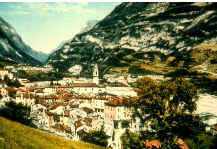
Vaiont Dam
新灘滑坡
新灘滑坡
三峽秭歸千將坪滑坡
三峽巴東滑坡
鏈子崖加固工程
TGP Layout
TGP Layout
TGP Shiplock
TGP Shi l k
TGP Shiplock Section
TGP Shiplock Section
TGP Rock Core
TGP Rock Core
Man Wan Dam
Man Wan Landslide Site
The landslide of the Manwan Hydropower ProjectJanuary 8 1989
云南小湾水电站左岸坝前边坡
开挖时面貌
湖南五強溪水庫滑坡
Da Lake
Xiao Lake
Yinping dam
Rockfallsource
Da Lake
四川大渡河滑坡壩(1933年大地震)
MUDFLOW OF THE LONGYANGXIA POWER STATION
Time of occurrenceAugust 4 of 1997 at 2355
Cause of the incidentA 2-hour constant rainfall with a total precipitation of 55 mm
Source of the mudflow material Natural deposit and construction waste in the Beidagou Gully
龙羊峡水电站128万千瓦
Geotechnical Issues (E) Tunnels and Excavations in Rock
- Fracture-induced instability (rock mass
classification and tunnel support design) - Stress-induced instability - Time-dependent deformation (eg Niagara vs
Three Gorges shiplocks)
Hoover Dam
Hoover Dam
廣州抽水蓄能電站
Two Types of Instability Underground
bull Stress ndash controlledbull Fracture - controlled
Rock Mass Classifications
bull Rock Quality Designation (RQD)
bull Rock Mass Rating System (RMR)
bull Rock Tunnelling Quality Index (Q)
Class Qualitative description BQ Value
I Hard rock intact gt 550
II Hard rock relatively intactRelatively hard rock intact
550 ~ 451
III Hard rock relatively fracturedRelatively hard or interlayered of hard and weak rock relatively
intactRelatively weak rock intact
450 ~ 351
IV Hard rock fracturedRelatively hard rock fractured-relatively fracturedRelatively weak rock or interlayered of weak and hard rock with dominant
weak rock relatively intact or relatively fracturedWeak rock intact or relatively intact
350 ~ 251
V Relatively weak rock fracturedWeak rock fractured-relatively fracturedExtremely weak rock extremely fractured
lt 250
National Standard for Engineering Classification of Rock Masses (GB 50218-94)
Table 1 Basic quality (BQ) of rock mass
BQ = 90 + 3 Rc + 250 Kv
where Rc = uniaxial compressive strength (MPa)Kv = intactness index of rock mass
Table 2 Classification based on uniaxial compressive strength Rc
Rc (MPa) gt 60 60 ~ 30 30 ~ 15 15 ~ 5 lt 5
Description Hard rock Relatively hard rock
Relatively weak rock
Weak rock Extremely weak rock
Table 4 Intactness Factor Kv as a function of Joint Index Jv
Jv (number of joints
m3)
lt 3 3 ~ 10 10 ~ 20 20 ~ 35 gt 35
Kv gt 075 075 ~ 055 055 ~ 035 035 ~ 015 lt 015
Kv =
Vpm= in-situ velocity of longitudinal elastic wave (kms)
Vpr = velocity of longitudinal elastic wave in intact rock (kms)
2
pt
pm
VV
⎟⎟⎠
⎞⎜⎜⎝
⎛
For engineering classification use [BQ] amended for groundwater joint orientation and in-situ stress conditions
[BQ] = BQ ndash 100 (K1 + K2 + K3)
where BQ = basic quality
K1 = correction factor for groundwater
K2 = correction factor for orientation of planes of weakness
K3 = correction factor for in-situ stress conditions
Table 5 K1 values - Correction factor for groundwater conditions
gt450 450 ~ 351 350 ~251 lt250
Wet or drops 0 01 02 ~ 03 04 ~ 06
Shower or flowP lt 01 MPa
Q lt 10 L min m
01 02 ~ 03 04 ~ 06 07 ~ 09
Shower or flowP lt01 MPa
Q lt 10 L min m
02 10
BQK1
Groundwaterinflow
Table 6 K2 values - Correction factor for orientation of planes of weakness
Relation of structure plane to tunnel axis
α lt 30 o= 30 o ~ 75 o
α gt 30 oβ gt 75 o
Other combinations
K2 04 ~ 06 0 ~ 02 02 ~ 04
α - angle between strike of structure plane and tunnel axisβ - dipping angle of structure plane
Table 7 K3 values - Correction factor for in-situ stress conditions
gt 550 550 ~ 351 450 ~ 351 350 ~251 lt 250
Extremely high stress
10 10 10 ~ 15 10 ~ 15 10
High stress 05 05 05 05 ~ 10 05 ~ 10
BQK3
Initialstress state
Technical Specifications for Water Resources and Hydropower ProjectsRock Mass Rating for Tunnelling Projects
Rock class
Rock stability Host rock
rating
StrengthStress S Support type
I Stable long termstability generally no unstable block
100 ~ 85 gt 4 No support or locally bolting or thin shotcreting in case of large span systematic shotcrete bolt and meshII Basically stable no
plasticity deformation85 ~ 65 gt 4
if S lt 4go to III
III Poor stability locally plasticity deformation or collapse
65 ~ 45 gt 2if S lt 2go to IV
Systematic shotcrete bolt and mesh if span = 20 ~ 25 m concrete lining is needed
IV Unstable short self-standing time large scale collapse
45 ~ 25 gt 2if S lt 2go to V
Systematic shotcrete bolt and mesh and concrete lining
V Extremely unstable severe collapse
lt 25 No limits
Host rock rating (HRR) = A + B + C + D + E(somewhat similar to Bieniawskirsquos RMR)
Rating on rock strength (A)
Type of rock materialHard rock Weak rock
Hard rock Moderately hard rock
Relatively weak rock
Weak rock
Uniaxial strength of saturated rock (MPa)
100 ~ 60 60 ~ 30 30 ~ 15 15 ~ 5
Rating (A)Hard rock 30 ~ 20 20 ~ 10
Weak rock 10 ~ 5 5 ~ 0
For uniaxial strength σc gt 100 MPa rock mass rating is 30
Rating on rock intactness (B)
Intactness Intact Relatively intact
Poor intactness
Relatively fractured
Fractured
Intactness factor Kv 10 ~ 075 075 ~ 055 055 ~ 035 035 ~ 015 lt 015
Hard rock 40 ~ 30 30 ~ 22 22 ~ 14 14 ~ 6 lt 6
Weak rock 25 ~ 19 19 ~ 14 14 ~ 9 9 ~ 4 lt 4
Rating (B)
Rating on state of structure planes (C)
Aperture (mm) Filling Roughness evenness Hard rock Relatively weak rock Weak rock
Closed lt 05Undulating rough 27 27 18
Planar smooth 21 21 14
Slight open 05 ~ 50
No filling Undulating rough 24 24 17Undulating smooth or
planar rough21 21 14
Planar smooth 15 15 8
Slacks
Undulating rough 21 21 14
Undulating smooth or planar rough
17 17 11
Planar smooth 12 12 8
Mud
Undulating rough 15 15 10
Undulating smooth or planar rough
12 12 8
Open gt 50
Planar smooth 9 9 6
Slacks 12 12 8Mud 6 6 4
For a length of structure plane which is less than 3 m in hard rock and relatively weak rock rating would increase by 3 for weak rock rating would increase by 2 For length gt 10 m decrease rating by 3 and 2 respectively for hard rock and relatively weak rock If aperture gt 10 m without filling rating is 0
Rating on groundwater condition (D)
Basic rating(A + B + C)
State Wet Drops Linear Flow Flow
Quantity of flow
(Lminm)
lt 25or
lt 10
25-125or
10-100
gt 125or
gt 100
Water head(m)
100-85
Rating on Groundwater Conditions
(D)
0 0 -2 ~ -6
85-65 0 ~ -2 0 ~ -2 -6 ~ -10
65-45 -2 ~ -6 -2 ~ -6 -10 ~ -14
45 ~ 25 -6 ~ -10 -10 ~ -14 -14 ~ -18
lt 25 -10 ~ -14 -14 ~ -18 -18 ~ -20
Rating on orientation of structure planes (E)
Angle betweenstrike of
structure planeand tunnel axis
( o )
90o ~ 60o 60o ~ 30o lt 30o
Dipping angle( o )
gt70 75~45 45~20 lt20 gt70 75~45 45~20 45~20
Crown -2
Wall -5
-5
-2
-12-10-10
0 -2 -5
-5
-10
lt20 gt70 70~45 lt20
0 -2 -12
0
-12-10
-12 0
-5
-2 -5 -10
Rating (E)
Factor Basis for Rating Rating
Saturated Compressive Strength (MPa) gt100 100-60 60-30 30-15 15-5
Rating for A gt30 30-20 20-10 10-5 5-0
Intactness Coefficient 10-075 075-055 055-035 035-015 lt015
σc gt 30 MPa 40-30 30-22 22-14 14-5 lt6
σc lt 30 MPa
Degree of openness
Infillings
Polishness of surface
σc gt 60 MPa
σc 60 - 30 MPa 27-21 24-15 21-12 15-9 12-6
18-14 17-8 14-8 10-6 8-4
gt10m
-3
-2
100-85
σc lt 30 MPa
70o- 45o 45o- 20o lt20o
-5 -10
0-2
-2
-5
σc gt 60 MPa
σc lt 60 MPa
Seeping dripping 0
Linear flow 0 rarr -2
-2 rarr -6
90o - 60o
gt70o
Roof 0
Sidewall -2
Gush of water
25-19 19-14 14-9 9-4 lt4
Closed lt05mm
Slightly open 05 ndash 50 mm Open gt 5 mm
Nil Rock fragments
Clay Fragmented Clay
Flat polished to curved rough
27-21 24-15 21-12 15-9 12-6
Length of structural surface lt3 m 3-10 m
+3 0
+2 0
A + B + C1 + C2 Rating 85-65 64-45 45-25 lt25
0 rarr -2 -2 rarr -6 -6 rarr -10 -10 rarr -14
-2 rarr -6 -6 rarr -10 -10 rarr -14 -14 rarr -18
-6 rarr -10 -10 rarr -14 -14 rarr -18 -18 rarr -20
Angle between tunnel alignment and structural orientation (strike)
60o - 30o lt 30o
Dip of structural orientation gt 70o 70o - 4 5o 45o - 20o lt 20o gt 70o 70o - 45o 45o - 20o lt 20o
2 -5 -10 -12 -5 -10 -12 -12
-5 -10 -2 0 -10 -12 -5 0
Rating for E
E
Rating for D
D
Rating for C2
C2
Rating for C1
Structural surface condition
C1
Rating for B
B
A
Host Rock Rating (HRR)
Recommended rock parameters
Class Gravity density γ(kNm3)
Friction angle ϕ (o)
Cohesion C(MPa)
Deformation module E(MPa)
Poisson ratio ν
I gt 60 gt 21 gt 33 lt 02
II 60 ~ 50 21 ~ 15 33 ~ 20 02 ~ 025
III 265 ~ 245 50 ~ 39 15 ~ 07 20 ~ 6 025 ~ 03
IV 245 ~ 225 39 ~ 27 07 ~ 02 6 ~ 13 03 ~ 035
V lt 225 lt 27 lt 02 lt 13 gt 035
gt 265
Recommended rock strength parameters
ClassConcrete-rock contact Rock mass Deformation
modulus
fprime cprime (MPa) fprime cprime (MPa) E0 X 104 (MPa)
I 15 ~ 13 15 ~ 13 16 ~ 14 25 ~ 20 gt 20
II 13 ~ 11 13 ~ 11 14 ~ 12 20 ~ 15 20 ~ 10
III 11 ~ 09 11 ~ 07 12 ~ 08 15 ~ 07 10 ~ 05
IV 09 ~ 07 07 ~ 03 08 ~ 055 07 ~ 03 05 ~ 02
V 07 ~ 04 03 ~ 005 055 ~ 040 03 ~ 005 02 ~ 002
fprime cprime - Shear strength
Design Applications of HRR
Rock PropertiesRock Type
Rock Mass Stability Host Rock
Rating (HRR)
Strength vs Stress Ratio (S) f C (MPa) E(x 104MPa)
Support Requirements
I Stable with long-term stability no unstable blocks in general
100 - 85 16 - 14 25 - 20 gt 20 Unsupported or localized boltsshotcrete or thin shotcrete add wire mesh for tunnels with large span
II Essentially stable with overall stability no plastic deformation localized rockfall
85 - 65 Downgrade to III for S lt 4
14 - 12 20 - 15 20 - 10
III Poor stability localized plastic deformation cave-in if unsupported temporarily stable in intact relatively soft rock
65 - 45 Downgrade to IV for S lt 2
12 - 08 15 - 07 10 - 05 Bolts and shotcrete with wire mesh concrete lining for tunnel span of 20 -25 m
IV Unstable very short standup time relatively large deformationfailure may occur
45 - 25 Downgrade to V for S lt 1
08 - 055 07 - 03 05 - 02 Bolts and shotcrete with re-bar mesh and concrete lining
V Very unstable could not stand up severe deformationfailure
lt 25 055 - 040 03 - 005 02 - 002
SUPPORT PARAMETERS(National Standard for Design of Bolt-shotcrete Support)
Span (m)Rock Class
B lt 5 m 5 lt B lt 10 10 lt B lt 20 15 lt B lt 20 20 lt B lt 25 m
I No support Shotcrete50 mm
(1) Shotcrete 80-100 mm(2) Shotcrete 50 mmbolt 20-25 m
Shotcrete Shotcrete 120-150 mmwith mesh bolt 30-40 m
II Shotcrete50 mm
(1) Shotcrete 80-100 mm(2) Shotcrete 50 mmbolt 15-2m
(1) Shotcrete 120-150 mm mesh if necessary(2) Shotcrete 80-120 mmbolt 2-3 m mesh if necessary
Shotcrete 120-150 mmmesh bolt 25-30 m
Shotcrete 150-200 mmmesh bolt 3-4 m
III (1) Shotcrete 80-100 mm(2) Shotcrete 50 mmbolt 15-2 m
(1) Shotcrete 120-150 mm mesh if necessary(2) Shotcrete 80-120 mmbolt 2-3 m mesh if necessary
Shotcrete 100-150 mmmesh bolt 20-30 m
Shotcrete 150-200 mmmesh bolt 3-4 m
IV Shotcrete 80-100 mmbolt 15-20 m
Shotcrete 100-200 mmmesh bolt 20-25 m bottom arch if necessary
Shotcrete 150-200 mmmesh bolt 25-30 m bottom arch if necessary
V Shotcrete 120-150 mmmesh bolt 15-20 m bottom arch if necessary
Shotcrete 150-200 mmmesh bolt 20-30 m bottom frame if necessary
GB-J86-85 (Revised)
Comparison of Rock Mass Classification Systems
System Range of Classes
Main Factors
Q 001-1000
9 RQD Jn (joint set number) Jr (joint roughness number) Ja (joint alteration number) Stress reduction factor SRF
RMR 0-100 5 Rock strength RQD Spacing conditions and orientation of joints Groundwater
HRR 0-100 5 Rock strength Intactness Conditions and Orientation of Weakness Planes Groundwater Initial Stresses
BQ lt 250-gt 500
5 Rock strength Intactness Groundwater Orientation of Weakness Planes Initial Stresses
Important Factors that are common among the various systems
1 Rock strength
2 Intactness
3 Condition of planes of weakness
4 Groundwater
5 Orientation of discontinuities
6 Initial stresses
Support systems for underground excavations in ChinaRock Class Span (m) Shotcrete Steel Mesh Bolt Concrete Lining
Total Number
of Projects
Thickness (cm)
Diameters(mm)
Spacing (m)
Diameter (mm)
Length (m)
Spacing (m)
Thickness(cm)
Number of Works
I 5-10 3-15 no no 18-22 12-30 Random no 9
10-15 3-20 6-12 025-15 18-22 15-35 10-15 no 9
15-20 10-20 no no 20-22 10-30 10-15 no 3
II 5-10 5-15 6-10 02-13 16-20 12-21 10-12 no 2 10
10-15 4-20 6-18 02-13 18-22 15-35 08-15 30-50 13
15-20 8-16 8-12 02-13 16-32 20-40 12-15 no 10
III 5-10 5-20 6-10 02-10 18-22 16-30 10-15 wall 1 12
10-15 5-20 5-12 02-10 16-24 15-35 10-15 11
15-20 10-16 6-12 02-08 16-30 20-40 08-12 8
IV 5-10 15-20 6-14 02-025 18-22 18-40 075-125 40 4 10
10-15 5-20 6-12 02-03 16-22 25-40 08-125 50 2 5
15-20 20 10-19 025 22 20 12 1
V 5-10 10-15 8-14 02-025 16-22 15-36 08-12 40 2
4
7
10-15 18-20 6-12 02-03 20-22 25-35 08-10 60 4
Three Gorges ProjectAmended [BQ] Values for Granite
Maximum [BQ]max = 630
Minimum [BQ]min = 500
Average [BQ]mean = 565
Class I- to II+
Guangzhou Pumped Storage Project
bull Location north of Guangzhou Guangdong Province
bull Underground Powerhouse
1465 m x 22 m x 445 m (L x W x H)
at 330 - 400 m depth completed in 1993
bull Host Rock Biotite granite
bull Support System Bolts (at 2 x 15 m spacing)+ 15 cm shotcrete in both crown and
sidewalls
Xiaolangdi Project
bull Location on Yellow River Henan Provincebull Underground Powerhouse
2515 m x 262 m x 614m (L x W x H)At 70 ndash 100 m depth completed in 1999
bull Host Rock Sandstone with argillaceous bedsbull Support System Bolts (at 15 spacing) with wiremesh
and shotcret (20 cm) in crownBolts (at 15 spacing) in sidewallsAnchors locally where required
Xiaolangdi Project on Yellow RiverProposed support parameters in design stage
Support DesignCavern Type Location Rock Type
Rock Grade Tensile Bolt Re Shotcrete
Top T14 III Φ 25 15 X 15 m (mortar bolt)
L = 53 m (alternatively)Φ 6 20 X 20 cmδ = 10 cm (C20)
Tailrace Cavern
Top T14 III Φ 28 15 X 15 m
L = 84 m (alternatively)Φ 8 20 X 20 cmδ = 20 cm (C20)
Sidewall T14
T13-2
III Φ 25 15 X 15 mL = 128 m (alternatively)
Φ 8 20 X 20 cmδ = 15 cm (C20)
Top T14 II- Φ 25 15 X 15 m
L = 73 m (alternatively)Φ 6 20 X 20 cmδ = 15 cm (C20)
Sidewall T14 II- Φ 25 15 X 15 m
L = 53 m (alternatively)Φ 6 20 X 20 cmδ = 10 cm (C20)
Sidewall T14 III Φ 25 15 X 15 m (mortar bolt)
L = 4 mΦ 6 25 X 25 cmδ = 10 cm (C20)
Transformer Cavern
Main Power-house
T14 thick to massive siliceous fine-grained sandstone
T13-2 thick to massive argillaceous and calcareous silty fine-grained sandstone
Xiaolangdi Project on Yellow RiverActual support used at construction stage
Support DesignCavern Type Location Rock Type
Rock Grade Tensile Bolt Re Shotcrete
Support Pres
(MPa)0112
0056
0104
0104
056
0044
Top T14 III Φ 32 3 X 3 m L = 5 m P = 150 KN
Φ 32 3 X 3 m L = 3 m P = 150 KNΦ 6 25 X 25 cmδ = 15 cm (C20)
Tailrace Cavern
Top T14 III Φ 32 3 X 3 m L = 8 m P = 150 KN
Φ 32 3 X 3 m L = 6 m P = 150 KNCable L = 25 m 45 X 6 m P = 1500 KN
Φ 8 20 X 20 cmδ = 20 cm (C20)
Sidewall T14
T13-2
III Φ 32 3 X 3 m L = 10 m P = 150 KNΦ 32 3 X 3 m L = 6 m P = 150 KNTwo rows of pre-stressed bolt added for argillized interlayers 500 KN L = 15 m
Φ 8 20 X 20 cmδ = 20 cm (C20)
Top T14 II- Φ 32 24 X 24 m L = 8 m P = 150 KN
Φ 32 24 X 24 m L = 4 m P = 150 KNΦ 6 20 X 20 cmδ = 20 cm (C20)
Sidewall T14 II- Φ 32 24 X 24 m L = 6 m P = 150 KN
Φ 32 24 X 24 m L = 4 m P = 150 KNΦ 6 25 X 25 cmδ = 15 cm (C20)
Sidewall T14 III Φ 32 15 X 15 m
L = 4 m P = 100 KNΦ 6 25 X 25 cmδ = 10 cm (C20)
Transformer Cavern
Main Power-house
Er Tan Dam
Er Tan Dam
Er Tan Dam Layout
Er Tan Dam Layout
Er Tan Under Construction
Er Tan Under Construction
Er Tan Underground Power House
Er Tan Underground Power House
Er Tan Diversion Tunnel
Er Tan Diversion Tunnel
Er Tan Rock Discing
Er Tan Rock Discing
Er Tan Geostress
Er Tan Geostress(kgcm2)
Strain Energy Approach to Modelling Rock Squeeze Problems
For a virtual displacement δ e
Work Done = Force x Displacement = Feδ e = (δ e)TFe
where Fe = corresponding nodal force Strain energy recovered from unit volume of rock = Stress x Strain = σ ε = ε Tσ = ([B] δ e)T ([D]ε ) = (δ e)T[B][D] ε Work Done = Strain Energy Released (δ e)TFe = (δ e)T int vol [B]T[D] ε dv
or Fe = int vol [B]T[D] ε dv
Some Features of Chinese Hydro Projects
bull Same design framework as in the Westbull Very detailed site investigationsbull Including numerous aditsbull Sometimes leads to significant cost savingsbull (eg Ertan dam allowed to be founded on Class III
rock instead of Class II as called for by Design Standard
bull Strong emphasis on geology and rock mass structure studies
bull Very detailed analysis including numerical modelling AI etc
青海龍羊峽
青海 黃河 李家峽 拱壩壩址
青海 李家峽
探洞
滑面
滑面
李家峽水庫 老滑坡體
剖面
電力需求增長
水電資源
Schematic Map of Hydropower Stations of 1GW and above in Operation or Under Construction
Jin Sha River Hydro Power
南水北調三線
Method of Generation Pros Cons
Capital Construction Cost
(Ratio) Fuel Cost
Fossil
bull Short construction period (2-3 years)
bull Easy to start up
bull Air pollution bull Ashsludge
disposal 1 Relatively high
Hydraulic
bull Longer construction period (gt 5 years)
bull Resettlement of affected population
bull Preservation of cultural amp historic relics
2
Nuclear
bull Relatively long construction period (ge 10 years)
bull Nuclear safety concern
bull Nuclear waste disposal needs
5 Relatively low
Other generation methods solar wind biomass etc
The Joy of being a Hydro Project Engineer
bull Free helicopter jet rides(safe most of the time)
bull Exotic places with breathtaking scenerysceneryand colorful folklore(no tourists around no phone calls etc)
攔路酒(四川 涼山)
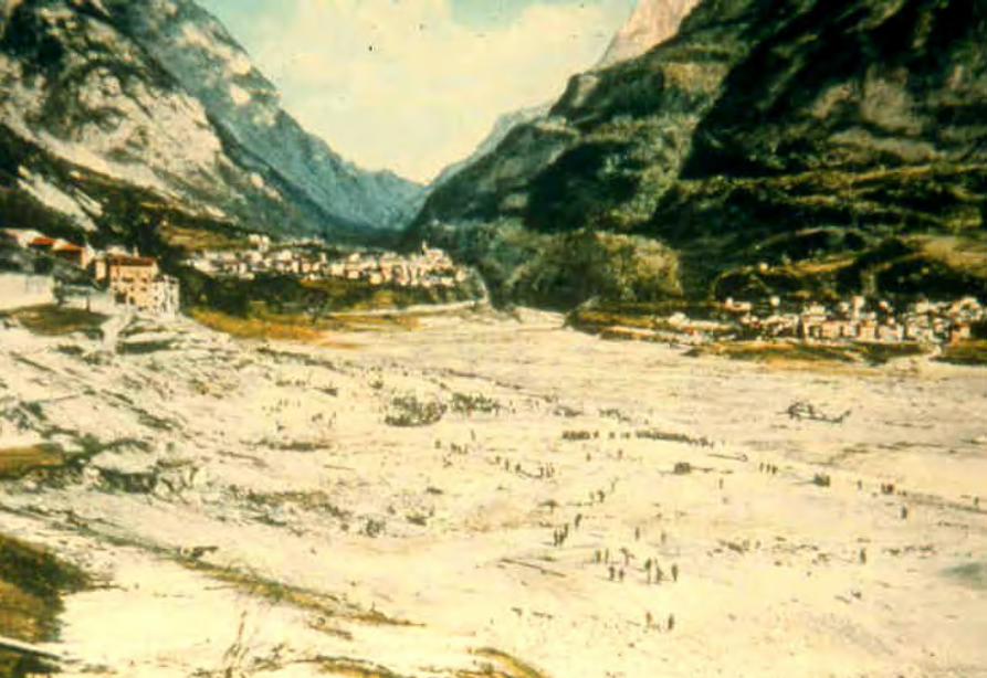
新灘滑坡
新灘滑坡
三峽秭歸千將坪滑坡
三峽巴東滑坡
鏈子崖加固工程
TGP Layout
TGP Layout
TGP Shiplock
TGP Shi l k
TGP Shiplock Section
TGP Shiplock Section
TGP Rock Core
TGP Rock Core
Man Wan Dam
Man Wan Landslide Site
The landslide of the Manwan Hydropower ProjectJanuary 8 1989
云南小湾水电站左岸坝前边坡
开挖时面貌
湖南五強溪水庫滑坡
Da Lake
Xiao Lake
Yinping dam
Rockfallsource
Da Lake
四川大渡河滑坡壩(1933年大地震)
MUDFLOW OF THE LONGYANGXIA POWER STATION
Time of occurrenceAugust 4 of 1997 at 2355
Cause of the incidentA 2-hour constant rainfall with a total precipitation of 55 mm
Source of the mudflow material Natural deposit and construction waste in the Beidagou Gully
龙羊峡水电站128万千瓦
Geotechnical Issues (E) Tunnels and Excavations in Rock
- Fracture-induced instability (rock mass
classification and tunnel support design) - Stress-induced instability - Time-dependent deformation (eg Niagara vs
Three Gorges shiplocks)
Hoover Dam
Hoover Dam
廣州抽水蓄能電站
Two Types of Instability Underground
bull Stress ndash controlledbull Fracture - controlled
Rock Mass Classifications
bull Rock Quality Designation (RQD)
bull Rock Mass Rating System (RMR)
bull Rock Tunnelling Quality Index (Q)
Class Qualitative description BQ Value
I Hard rock intact gt 550
II Hard rock relatively intactRelatively hard rock intact
550 ~ 451
III Hard rock relatively fracturedRelatively hard or interlayered of hard and weak rock relatively
intactRelatively weak rock intact
450 ~ 351
IV Hard rock fracturedRelatively hard rock fractured-relatively fracturedRelatively weak rock or interlayered of weak and hard rock with dominant
weak rock relatively intact or relatively fracturedWeak rock intact or relatively intact
350 ~ 251
V Relatively weak rock fracturedWeak rock fractured-relatively fracturedExtremely weak rock extremely fractured
lt 250
National Standard for Engineering Classification of Rock Masses (GB 50218-94)
Table 1 Basic quality (BQ) of rock mass
BQ = 90 + 3 Rc + 250 Kv
where Rc = uniaxial compressive strength (MPa)Kv = intactness index of rock mass
Table 2 Classification based on uniaxial compressive strength Rc
Rc (MPa) gt 60 60 ~ 30 30 ~ 15 15 ~ 5 lt 5
Description Hard rock Relatively hard rock
Relatively weak rock
Weak rock Extremely weak rock
Table 4 Intactness Factor Kv as a function of Joint Index Jv
Jv (number of joints
m3)
lt 3 3 ~ 10 10 ~ 20 20 ~ 35 gt 35
Kv gt 075 075 ~ 055 055 ~ 035 035 ~ 015 lt 015
Kv =
Vpm= in-situ velocity of longitudinal elastic wave (kms)
Vpr = velocity of longitudinal elastic wave in intact rock (kms)
2
pt
pm
VV
⎟⎟⎠
⎞⎜⎜⎝
⎛
For engineering classification use [BQ] amended for groundwater joint orientation and in-situ stress conditions
[BQ] = BQ ndash 100 (K1 + K2 + K3)
where BQ = basic quality
K1 = correction factor for groundwater
K2 = correction factor for orientation of planes of weakness
K3 = correction factor for in-situ stress conditions
Table 5 K1 values - Correction factor for groundwater conditions
gt450 450 ~ 351 350 ~251 lt250
Wet or drops 0 01 02 ~ 03 04 ~ 06
Shower or flowP lt 01 MPa
Q lt 10 L min m
01 02 ~ 03 04 ~ 06 07 ~ 09
Shower or flowP lt01 MPa
Q lt 10 L min m
02 10
BQK1
Groundwaterinflow
Table 6 K2 values - Correction factor for orientation of planes of weakness
Relation of structure plane to tunnel axis
α lt 30 o= 30 o ~ 75 o
α gt 30 oβ gt 75 o
Other combinations
K2 04 ~ 06 0 ~ 02 02 ~ 04
α - angle between strike of structure plane and tunnel axisβ - dipping angle of structure plane
Table 7 K3 values - Correction factor for in-situ stress conditions
gt 550 550 ~ 351 450 ~ 351 350 ~251 lt 250
Extremely high stress
10 10 10 ~ 15 10 ~ 15 10
High stress 05 05 05 05 ~ 10 05 ~ 10
BQK3
Initialstress state
Technical Specifications for Water Resources and Hydropower ProjectsRock Mass Rating for Tunnelling Projects
Rock class
Rock stability Host rock
rating
StrengthStress S Support type
I Stable long termstability generally no unstable block
100 ~ 85 gt 4 No support or locally bolting or thin shotcreting in case of large span systematic shotcrete bolt and meshII Basically stable no
plasticity deformation85 ~ 65 gt 4
if S lt 4go to III
III Poor stability locally plasticity deformation or collapse
65 ~ 45 gt 2if S lt 2go to IV
Systematic shotcrete bolt and mesh if span = 20 ~ 25 m concrete lining is needed
IV Unstable short self-standing time large scale collapse
45 ~ 25 gt 2if S lt 2go to V
Systematic shotcrete bolt and mesh and concrete lining
V Extremely unstable severe collapse
lt 25 No limits
Host rock rating (HRR) = A + B + C + D + E(somewhat similar to Bieniawskirsquos RMR)
Rating on rock strength (A)
Type of rock materialHard rock Weak rock
Hard rock Moderately hard rock
Relatively weak rock
Weak rock
Uniaxial strength of saturated rock (MPa)
100 ~ 60 60 ~ 30 30 ~ 15 15 ~ 5
Rating (A)Hard rock 30 ~ 20 20 ~ 10
Weak rock 10 ~ 5 5 ~ 0
For uniaxial strength σc gt 100 MPa rock mass rating is 30
Rating on rock intactness (B)
Intactness Intact Relatively intact
Poor intactness
Relatively fractured
Fractured
Intactness factor Kv 10 ~ 075 075 ~ 055 055 ~ 035 035 ~ 015 lt 015
Hard rock 40 ~ 30 30 ~ 22 22 ~ 14 14 ~ 6 lt 6
Weak rock 25 ~ 19 19 ~ 14 14 ~ 9 9 ~ 4 lt 4
Rating (B)
Rating on state of structure planes (C)
Aperture (mm) Filling Roughness evenness Hard rock Relatively weak rock Weak rock
Closed lt 05Undulating rough 27 27 18
Planar smooth 21 21 14
Slight open 05 ~ 50
No filling Undulating rough 24 24 17Undulating smooth or
planar rough21 21 14
Planar smooth 15 15 8
Slacks
Undulating rough 21 21 14
Undulating smooth or planar rough
17 17 11
Planar smooth 12 12 8
Mud
Undulating rough 15 15 10
Undulating smooth or planar rough
12 12 8
Open gt 50
Planar smooth 9 9 6
Slacks 12 12 8Mud 6 6 4
For a length of structure plane which is less than 3 m in hard rock and relatively weak rock rating would increase by 3 for weak rock rating would increase by 2 For length gt 10 m decrease rating by 3 and 2 respectively for hard rock and relatively weak rock If aperture gt 10 m without filling rating is 0
Rating on groundwater condition (D)
Basic rating(A + B + C)
State Wet Drops Linear Flow Flow
Quantity of flow
(Lminm)
lt 25or
lt 10
25-125or
10-100
gt 125or
gt 100
Water head(m)
100-85
Rating on Groundwater Conditions
(D)
0 0 -2 ~ -6
85-65 0 ~ -2 0 ~ -2 -6 ~ -10
65-45 -2 ~ -6 -2 ~ -6 -10 ~ -14
45 ~ 25 -6 ~ -10 -10 ~ -14 -14 ~ -18
lt 25 -10 ~ -14 -14 ~ -18 -18 ~ -20
Rating on orientation of structure planes (E)
Angle betweenstrike of
structure planeand tunnel axis
( o )
90o ~ 60o 60o ~ 30o lt 30o
Dipping angle( o )
gt70 75~45 45~20 lt20 gt70 75~45 45~20 45~20
Crown -2
Wall -5
-5
-2
-12-10-10
0 -2 -5
-5
-10
lt20 gt70 70~45 lt20
0 -2 -12
0
-12-10
-12 0
-5
-2 -5 -10
Rating (E)
Factor Basis for Rating Rating
Saturated Compressive Strength (MPa) gt100 100-60 60-30 30-15 15-5
Rating for A gt30 30-20 20-10 10-5 5-0
Intactness Coefficient 10-075 075-055 055-035 035-015 lt015
σc gt 30 MPa 40-30 30-22 22-14 14-5 lt6
σc lt 30 MPa
Degree of openness
Infillings
Polishness of surface
σc gt 60 MPa
σc 60 - 30 MPa 27-21 24-15 21-12 15-9 12-6
18-14 17-8 14-8 10-6 8-4
gt10m
-3
-2
100-85
σc lt 30 MPa
70o- 45o 45o- 20o lt20o
-5 -10
0-2
-2
-5
σc gt 60 MPa
σc lt 60 MPa
Seeping dripping 0
Linear flow 0 rarr -2
-2 rarr -6
90o - 60o
gt70o
Roof 0
Sidewall -2
Gush of water
25-19 19-14 14-9 9-4 lt4
Closed lt05mm
Slightly open 05 ndash 50 mm Open gt 5 mm
Nil Rock fragments
Clay Fragmented Clay
Flat polished to curved rough
27-21 24-15 21-12 15-9 12-6
Length of structural surface lt3 m 3-10 m
+3 0
+2 0
A + B + C1 + C2 Rating 85-65 64-45 45-25 lt25
0 rarr -2 -2 rarr -6 -6 rarr -10 -10 rarr -14
-2 rarr -6 -6 rarr -10 -10 rarr -14 -14 rarr -18
-6 rarr -10 -10 rarr -14 -14 rarr -18 -18 rarr -20
Angle between tunnel alignment and structural orientation (strike)
60o - 30o lt 30o
Dip of structural orientation gt 70o 70o - 4 5o 45o - 20o lt 20o gt 70o 70o - 45o 45o - 20o lt 20o
2 -5 -10 -12 -5 -10 -12 -12
-5 -10 -2 0 -10 -12 -5 0
Rating for E
E
Rating for D
D
Rating for C2
C2
Rating for C1
Structural surface condition
C1
Rating for B
B
A
Host Rock Rating (HRR)
Recommended rock parameters
Class Gravity density γ(kNm3)
Friction angle ϕ (o)
Cohesion C(MPa)
Deformation module E(MPa)
Poisson ratio ν
I gt 60 gt 21 gt 33 lt 02
II 60 ~ 50 21 ~ 15 33 ~ 20 02 ~ 025
III 265 ~ 245 50 ~ 39 15 ~ 07 20 ~ 6 025 ~ 03
IV 245 ~ 225 39 ~ 27 07 ~ 02 6 ~ 13 03 ~ 035
V lt 225 lt 27 lt 02 lt 13 gt 035
gt 265
Recommended rock strength parameters
ClassConcrete-rock contact Rock mass Deformation
modulus
fprime cprime (MPa) fprime cprime (MPa) E0 X 104 (MPa)
I 15 ~ 13 15 ~ 13 16 ~ 14 25 ~ 20 gt 20
II 13 ~ 11 13 ~ 11 14 ~ 12 20 ~ 15 20 ~ 10
III 11 ~ 09 11 ~ 07 12 ~ 08 15 ~ 07 10 ~ 05
IV 09 ~ 07 07 ~ 03 08 ~ 055 07 ~ 03 05 ~ 02
V 07 ~ 04 03 ~ 005 055 ~ 040 03 ~ 005 02 ~ 002
fprime cprime - Shear strength
Design Applications of HRR
Rock PropertiesRock Type
Rock Mass Stability Host Rock
Rating (HRR)
Strength vs Stress Ratio (S) f C (MPa) E(x 104MPa)
Support Requirements
I Stable with long-term stability no unstable blocks in general
100 - 85 16 - 14 25 - 20 gt 20 Unsupported or localized boltsshotcrete or thin shotcrete add wire mesh for tunnels with large span
II Essentially stable with overall stability no plastic deformation localized rockfall
85 - 65 Downgrade to III for S lt 4
14 - 12 20 - 15 20 - 10
III Poor stability localized plastic deformation cave-in if unsupported temporarily stable in intact relatively soft rock
65 - 45 Downgrade to IV for S lt 2
12 - 08 15 - 07 10 - 05 Bolts and shotcrete with wire mesh concrete lining for tunnel span of 20 -25 m
IV Unstable very short standup time relatively large deformationfailure may occur
45 - 25 Downgrade to V for S lt 1
08 - 055 07 - 03 05 - 02 Bolts and shotcrete with re-bar mesh and concrete lining
V Very unstable could not stand up severe deformationfailure
lt 25 055 - 040 03 - 005 02 - 002
SUPPORT PARAMETERS(National Standard for Design of Bolt-shotcrete Support)
Span (m)Rock Class
B lt 5 m 5 lt B lt 10 10 lt B lt 20 15 lt B lt 20 20 lt B lt 25 m
I No support Shotcrete50 mm
(1) Shotcrete 80-100 mm(2) Shotcrete 50 mmbolt 20-25 m
Shotcrete Shotcrete 120-150 mmwith mesh bolt 30-40 m
II Shotcrete50 mm
(1) Shotcrete 80-100 mm(2) Shotcrete 50 mmbolt 15-2m
(1) Shotcrete 120-150 mm mesh if necessary(2) Shotcrete 80-120 mmbolt 2-3 m mesh if necessary
Shotcrete 120-150 mmmesh bolt 25-30 m
Shotcrete 150-200 mmmesh bolt 3-4 m
III (1) Shotcrete 80-100 mm(2) Shotcrete 50 mmbolt 15-2 m
(1) Shotcrete 120-150 mm mesh if necessary(2) Shotcrete 80-120 mmbolt 2-3 m mesh if necessary
Shotcrete 100-150 mmmesh bolt 20-30 m
Shotcrete 150-200 mmmesh bolt 3-4 m
IV Shotcrete 80-100 mmbolt 15-20 m
Shotcrete 100-200 mmmesh bolt 20-25 m bottom arch if necessary
Shotcrete 150-200 mmmesh bolt 25-30 m bottom arch if necessary
V Shotcrete 120-150 mmmesh bolt 15-20 m bottom arch if necessary
Shotcrete 150-200 mmmesh bolt 20-30 m bottom frame if necessary
GB-J86-85 (Revised)
Comparison of Rock Mass Classification Systems
System Range of Classes
Main Factors
Q 001-1000
9 RQD Jn (joint set number) Jr (joint roughness number) Ja (joint alteration number) Stress reduction factor SRF
RMR 0-100 5 Rock strength RQD Spacing conditions and orientation of joints Groundwater
HRR 0-100 5 Rock strength Intactness Conditions and Orientation of Weakness Planes Groundwater Initial Stresses
BQ lt 250-gt 500
5 Rock strength Intactness Groundwater Orientation of Weakness Planes Initial Stresses
Important Factors that are common among the various systems
1 Rock strength
2 Intactness
3 Condition of planes of weakness
4 Groundwater
5 Orientation of discontinuities
6 Initial stresses
Support systems for underground excavations in ChinaRock Class Span (m) Shotcrete Steel Mesh Bolt Concrete Lining
Total Number
of Projects
Thickness (cm)
Diameters(mm)
Spacing (m)
Diameter (mm)
Length (m)
Spacing (m)
Thickness(cm)
Number of Works
I 5-10 3-15 no no 18-22 12-30 Random no 9
10-15 3-20 6-12 025-15 18-22 15-35 10-15 no 9
15-20 10-20 no no 20-22 10-30 10-15 no 3
II 5-10 5-15 6-10 02-13 16-20 12-21 10-12 no 2 10
10-15 4-20 6-18 02-13 18-22 15-35 08-15 30-50 13
15-20 8-16 8-12 02-13 16-32 20-40 12-15 no 10
III 5-10 5-20 6-10 02-10 18-22 16-30 10-15 wall 1 12
10-15 5-20 5-12 02-10 16-24 15-35 10-15 11
15-20 10-16 6-12 02-08 16-30 20-40 08-12 8
IV 5-10 15-20 6-14 02-025 18-22 18-40 075-125 40 4 10
10-15 5-20 6-12 02-03 16-22 25-40 08-125 50 2 5
15-20 20 10-19 025 22 20 12 1
V 5-10 10-15 8-14 02-025 16-22 15-36 08-12 40 2
4
7
10-15 18-20 6-12 02-03 20-22 25-35 08-10 60 4
Three Gorges ProjectAmended [BQ] Values for Granite
Maximum [BQ]max = 630
Minimum [BQ]min = 500
Average [BQ]mean = 565
Class I- to II+
Guangzhou Pumped Storage Project
bull Location north of Guangzhou Guangdong Province
bull Underground Powerhouse
1465 m x 22 m x 445 m (L x W x H)
at 330 - 400 m depth completed in 1993
bull Host Rock Biotite granite
bull Support System Bolts (at 2 x 15 m spacing)+ 15 cm shotcrete in both crown and
sidewalls
Xiaolangdi Project
bull Location on Yellow River Henan Provincebull Underground Powerhouse
2515 m x 262 m x 614m (L x W x H)At 70 ndash 100 m depth completed in 1999
bull Host Rock Sandstone with argillaceous bedsbull Support System Bolts (at 15 spacing) with wiremesh
and shotcret (20 cm) in crownBolts (at 15 spacing) in sidewallsAnchors locally where required
Xiaolangdi Project on Yellow RiverProposed support parameters in design stage
Support DesignCavern Type Location Rock Type
Rock Grade Tensile Bolt Re Shotcrete
Top T14 III Φ 25 15 X 15 m (mortar bolt)
L = 53 m (alternatively)Φ 6 20 X 20 cmδ = 10 cm (C20)
Tailrace Cavern
Top T14 III Φ 28 15 X 15 m
L = 84 m (alternatively)Φ 8 20 X 20 cmδ = 20 cm (C20)
Sidewall T14
T13-2
III Φ 25 15 X 15 mL = 128 m (alternatively)
Φ 8 20 X 20 cmδ = 15 cm (C20)
Top T14 II- Φ 25 15 X 15 m
L = 73 m (alternatively)Φ 6 20 X 20 cmδ = 15 cm (C20)
Sidewall T14 II- Φ 25 15 X 15 m
L = 53 m (alternatively)Φ 6 20 X 20 cmδ = 10 cm (C20)
Sidewall T14 III Φ 25 15 X 15 m (mortar bolt)
L = 4 mΦ 6 25 X 25 cmδ = 10 cm (C20)
Transformer Cavern
Main Power-house
T14 thick to massive siliceous fine-grained sandstone
T13-2 thick to massive argillaceous and calcareous silty fine-grained sandstone
Xiaolangdi Project on Yellow RiverActual support used at construction stage
Support DesignCavern Type Location Rock Type
Rock Grade Tensile Bolt Re Shotcrete
Support Pres
(MPa)0112
0056
0104
0104
056
0044
Top T14 III Φ 32 3 X 3 m L = 5 m P = 150 KN
Φ 32 3 X 3 m L = 3 m P = 150 KNΦ 6 25 X 25 cmδ = 15 cm (C20)
Tailrace Cavern
Top T14 III Φ 32 3 X 3 m L = 8 m P = 150 KN
Φ 32 3 X 3 m L = 6 m P = 150 KNCable L = 25 m 45 X 6 m P = 1500 KN
Φ 8 20 X 20 cmδ = 20 cm (C20)
Sidewall T14
T13-2
III Φ 32 3 X 3 m L = 10 m P = 150 KNΦ 32 3 X 3 m L = 6 m P = 150 KNTwo rows of pre-stressed bolt added for argillized interlayers 500 KN L = 15 m
Φ 8 20 X 20 cmδ = 20 cm (C20)
Top T14 II- Φ 32 24 X 24 m L = 8 m P = 150 KN
Φ 32 24 X 24 m L = 4 m P = 150 KNΦ 6 20 X 20 cmδ = 20 cm (C20)
Sidewall T14 II- Φ 32 24 X 24 m L = 6 m P = 150 KN
Φ 32 24 X 24 m L = 4 m P = 150 KNΦ 6 25 X 25 cmδ = 15 cm (C20)
Sidewall T14 III Φ 32 15 X 15 m
L = 4 m P = 100 KNΦ 6 25 X 25 cmδ = 10 cm (C20)
Transformer Cavern
Main Power-house
Er Tan Dam
Er Tan Dam
Er Tan Dam Layout
Er Tan Dam Layout
Er Tan Under Construction
Er Tan Under Construction
Er Tan Underground Power House
Er Tan Underground Power House
Er Tan Diversion Tunnel
Er Tan Diversion Tunnel
Er Tan Rock Discing
Er Tan Rock Discing
Er Tan Geostress
Er Tan Geostress(kgcm2)
Strain Energy Approach to Modelling Rock Squeeze Problems
For a virtual displacement δ e
Work Done = Force x Displacement = Feδ e = (δ e)TFe
where Fe = corresponding nodal force Strain energy recovered from unit volume of rock = Stress x Strain = σ ε = ε Tσ = ([B] δ e)T ([D]ε ) = (δ e)T[B][D] ε Work Done = Strain Energy Released (δ e)TFe = (δ e)T int vol [B]T[D] ε dv
or Fe = int vol [B]T[D] ε dv
Some Features of Chinese Hydro Projects
bull Same design framework as in the Westbull Very detailed site investigationsbull Including numerous aditsbull Sometimes leads to significant cost savingsbull (eg Ertan dam allowed to be founded on Class III
rock instead of Class II as called for by Design Standard
bull Strong emphasis on geology and rock mass structure studies
bull Very detailed analysis including numerical modelling AI etc
青海龍羊峽
青海 黃河 李家峽 拱壩壩址
青海 李家峽
探洞
滑面
滑面
李家峽水庫 老滑坡體
剖面
電力需求增長
水電資源
Schematic Map of Hydropower Stations of 1GW and above in Operation or Under Construction
Jin Sha River Hydro Power
南水北調三線
Method of Generation Pros Cons
Capital Construction Cost
(Ratio) Fuel Cost
Fossil
bull Short construction period (2-3 years)
bull Easy to start up
bull Air pollution bull Ashsludge
disposal 1 Relatively high
Hydraulic
bull Longer construction period (gt 5 years)
bull Resettlement of affected population
bull Preservation of cultural amp historic relics
2
Nuclear
bull Relatively long construction period (ge 10 years)
bull Nuclear safety concern
bull Nuclear waste disposal needs
5 Relatively low
Other generation methods solar wind biomass etc
The Joy of being a Hydro Project Engineer
bull Free helicopter jet rides(safe most of the time)
bull Exotic places with breathtaking scenerysceneryand colorful folklore(no tourists around no phone calls etc)
攔路酒(四川 涼山)
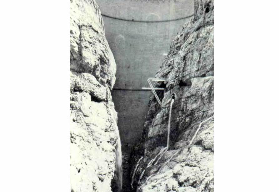
新灘滑坡
三峽秭歸千將坪滑坡
三峽巴東滑坡
鏈子崖加固工程
TGP Layout
TGP Layout
TGP Shiplock
TGP Shi l k
TGP Shiplock Section
TGP Shiplock Section
TGP Rock Core
TGP Rock Core
Man Wan Dam
Man Wan Landslide Site
The landslide of the Manwan Hydropower ProjectJanuary 8 1989
云南小湾水电站左岸坝前边坡
开挖时面貌
湖南五強溪水庫滑坡
Da Lake
Xiao Lake
Yinping dam
Rockfallsource
Da Lake
四川大渡河滑坡壩(1933年大地震)
MUDFLOW OF THE LONGYANGXIA POWER STATION
Time of occurrenceAugust 4 of 1997 at 2355
Cause of the incidentA 2-hour constant rainfall with a total precipitation of 55 mm
Source of the mudflow material Natural deposit and construction waste in the Beidagou Gully
龙羊峡水电站128万千瓦
Geotechnical Issues (E) Tunnels and Excavations in Rock
- Fracture-induced instability (rock mass
classification and tunnel support design) - Stress-induced instability - Time-dependent deformation (eg Niagara vs
Three Gorges shiplocks)
Hoover Dam
Hoover Dam
廣州抽水蓄能電站
Two Types of Instability Underground
bull Stress ndash controlledbull Fracture - controlled
Rock Mass Classifications
bull Rock Quality Designation (RQD)
bull Rock Mass Rating System (RMR)
bull Rock Tunnelling Quality Index (Q)
Class Qualitative description BQ Value
I Hard rock intact gt 550
II Hard rock relatively intactRelatively hard rock intact
550 ~ 451
III Hard rock relatively fracturedRelatively hard or interlayered of hard and weak rock relatively
intactRelatively weak rock intact
450 ~ 351
IV Hard rock fracturedRelatively hard rock fractured-relatively fracturedRelatively weak rock or interlayered of weak and hard rock with dominant
weak rock relatively intact or relatively fracturedWeak rock intact or relatively intact
350 ~ 251
V Relatively weak rock fracturedWeak rock fractured-relatively fracturedExtremely weak rock extremely fractured
lt 250
National Standard for Engineering Classification of Rock Masses (GB 50218-94)
Table 1 Basic quality (BQ) of rock mass
BQ = 90 + 3 Rc + 250 Kv
where Rc = uniaxial compressive strength (MPa)Kv = intactness index of rock mass
Table 2 Classification based on uniaxial compressive strength Rc
Rc (MPa) gt 60 60 ~ 30 30 ~ 15 15 ~ 5 lt 5
Description Hard rock Relatively hard rock
Relatively weak rock
Weak rock Extremely weak rock
Table 4 Intactness Factor Kv as a function of Joint Index Jv
Jv (number of joints
m3)
lt 3 3 ~ 10 10 ~ 20 20 ~ 35 gt 35
Kv gt 075 075 ~ 055 055 ~ 035 035 ~ 015 lt 015
Kv =
Vpm= in-situ velocity of longitudinal elastic wave (kms)
Vpr = velocity of longitudinal elastic wave in intact rock (kms)
2
pt
pm
VV
⎟⎟⎠
⎞⎜⎜⎝
⎛
For engineering classification use [BQ] amended for groundwater joint orientation and in-situ stress conditions
[BQ] = BQ ndash 100 (K1 + K2 + K3)
where BQ = basic quality
K1 = correction factor for groundwater
K2 = correction factor for orientation of planes of weakness
K3 = correction factor for in-situ stress conditions
Table 5 K1 values - Correction factor for groundwater conditions
gt450 450 ~ 351 350 ~251 lt250
Wet or drops 0 01 02 ~ 03 04 ~ 06
Shower or flowP lt 01 MPa
Q lt 10 L min m
01 02 ~ 03 04 ~ 06 07 ~ 09
Shower or flowP lt01 MPa
Q lt 10 L min m
02 10
BQK1
Groundwaterinflow
Table 6 K2 values - Correction factor for orientation of planes of weakness
Relation of structure plane to tunnel axis
α lt 30 o= 30 o ~ 75 o
α gt 30 oβ gt 75 o
Other combinations
K2 04 ~ 06 0 ~ 02 02 ~ 04
α - angle between strike of structure plane and tunnel axisβ - dipping angle of structure plane
Table 7 K3 values - Correction factor for in-situ stress conditions
gt 550 550 ~ 351 450 ~ 351 350 ~251 lt 250
Extremely high stress
10 10 10 ~ 15 10 ~ 15 10
High stress 05 05 05 05 ~ 10 05 ~ 10
BQK3
Initialstress state
Technical Specifications for Water Resources and Hydropower ProjectsRock Mass Rating for Tunnelling Projects
Rock class
Rock stability Host rock
rating
StrengthStress S Support type
I Stable long termstability generally no unstable block
100 ~ 85 gt 4 No support or locally bolting or thin shotcreting in case of large span systematic shotcrete bolt and meshII Basically stable no
plasticity deformation85 ~ 65 gt 4
if S lt 4go to III
III Poor stability locally plasticity deformation or collapse
65 ~ 45 gt 2if S lt 2go to IV
Systematic shotcrete bolt and mesh if span = 20 ~ 25 m concrete lining is needed
IV Unstable short self-standing time large scale collapse
45 ~ 25 gt 2if S lt 2go to V
Systematic shotcrete bolt and mesh and concrete lining
V Extremely unstable severe collapse
lt 25 No limits
Host rock rating (HRR) = A + B + C + D + E(somewhat similar to Bieniawskirsquos RMR)
Rating on rock strength (A)
Type of rock materialHard rock Weak rock
Hard rock Moderately hard rock
Relatively weak rock
Weak rock
Uniaxial strength of saturated rock (MPa)
100 ~ 60 60 ~ 30 30 ~ 15 15 ~ 5
Rating (A)Hard rock 30 ~ 20 20 ~ 10
Weak rock 10 ~ 5 5 ~ 0
For uniaxial strength σc gt 100 MPa rock mass rating is 30
Rating on rock intactness (B)
Intactness Intact Relatively intact
Poor intactness
Relatively fractured
Fractured
Intactness factor Kv 10 ~ 075 075 ~ 055 055 ~ 035 035 ~ 015 lt 015
Hard rock 40 ~ 30 30 ~ 22 22 ~ 14 14 ~ 6 lt 6
Weak rock 25 ~ 19 19 ~ 14 14 ~ 9 9 ~ 4 lt 4
Rating (B)
Rating on state of structure planes (C)
Aperture (mm) Filling Roughness evenness Hard rock Relatively weak rock Weak rock
Closed lt 05Undulating rough 27 27 18
Planar smooth 21 21 14
Slight open 05 ~ 50
No filling Undulating rough 24 24 17Undulating smooth or
planar rough21 21 14
Planar smooth 15 15 8
Slacks
Undulating rough 21 21 14
Undulating smooth or planar rough
17 17 11
Planar smooth 12 12 8
Mud
Undulating rough 15 15 10
Undulating smooth or planar rough
12 12 8
Open gt 50
Planar smooth 9 9 6
Slacks 12 12 8Mud 6 6 4
For a length of structure plane which is less than 3 m in hard rock and relatively weak rock rating would increase by 3 for weak rock rating would increase by 2 For length gt 10 m decrease rating by 3 and 2 respectively for hard rock and relatively weak rock If aperture gt 10 m without filling rating is 0
Rating on groundwater condition (D)
Basic rating(A + B + C)
State Wet Drops Linear Flow Flow
Quantity of flow
(Lminm)
lt 25or
lt 10
25-125or
10-100
gt 125or
gt 100
Water head(m)
100-85
Rating on Groundwater Conditions
(D)
0 0 -2 ~ -6
85-65 0 ~ -2 0 ~ -2 -6 ~ -10
65-45 -2 ~ -6 -2 ~ -6 -10 ~ -14
45 ~ 25 -6 ~ -10 -10 ~ -14 -14 ~ -18
lt 25 -10 ~ -14 -14 ~ -18 -18 ~ -20
Rating on orientation of structure planes (E)
Angle betweenstrike of
structure planeand tunnel axis
( o )
90o ~ 60o 60o ~ 30o lt 30o
Dipping angle( o )
gt70 75~45 45~20 lt20 gt70 75~45 45~20 45~20
Crown -2
Wall -5
-5
-2
-12-10-10
0 -2 -5
-5
-10
lt20 gt70 70~45 lt20
0 -2 -12
0
-12-10
-12 0
-5
-2 -5 -10
Rating (E)
Factor Basis for Rating Rating
Saturated Compressive Strength (MPa) gt100 100-60 60-30 30-15 15-5
Rating for A gt30 30-20 20-10 10-5 5-0
Intactness Coefficient 10-075 075-055 055-035 035-015 lt015
σc gt 30 MPa 40-30 30-22 22-14 14-5 lt6
σc lt 30 MPa
Degree of openness
Infillings
Polishness of surface
σc gt 60 MPa
σc 60 - 30 MPa 27-21 24-15 21-12 15-9 12-6
18-14 17-8 14-8 10-6 8-4
gt10m
-3
-2
100-85
σc lt 30 MPa
70o- 45o 45o- 20o lt20o
-5 -10
0-2
-2
-5
σc gt 60 MPa
σc lt 60 MPa
Seeping dripping 0
Linear flow 0 rarr -2
-2 rarr -6
90o - 60o
gt70o
Roof 0
Sidewall -2
Gush of water
25-19 19-14 14-9 9-4 lt4
Closed lt05mm
Slightly open 05 ndash 50 mm Open gt 5 mm
Nil Rock fragments
Clay Fragmented Clay
Flat polished to curved rough
27-21 24-15 21-12 15-9 12-6
Length of structural surface lt3 m 3-10 m
+3 0
+2 0
A + B + C1 + C2 Rating 85-65 64-45 45-25 lt25
0 rarr -2 -2 rarr -6 -6 rarr -10 -10 rarr -14
-2 rarr -6 -6 rarr -10 -10 rarr -14 -14 rarr -18
-6 rarr -10 -10 rarr -14 -14 rarr -18 -18 rarr -20
Angle between tunnel alignment and structural orientation (strike)
60o - 30o lt 30o
Dip of structural orientation gt 70o 70o - 4 5o 45o - 20o lt 20o gt 70o 70o - 45o 45o - 20o lt 20o
2 -5 -10 -12 -5 -10 -12 -12
-5 -10 -2 0 -10 -12 -5 0
Rating for E
E
Rating for D
D
Rating for C2
C2
Rating for C1
Structural surface condition
C1
Rating for B
B
A
Host Rock Rating (HRR)
Recommended rock parameters
Class Gravity density γ(kNm3)
Friction angle ϕ (o)
Cohesion C(MPa)
Deformation module E(MPa)
Poisson ratio ν
I gt 60 gt 21 gt 33 lt 02
II 60 ~ 50 21 ~ 15 33 ~ 20 02 ~ 025
III 265 ~ 245 50 ~ 39 15 ~ 07 20 ~ 6 025 ~ 03
IV 245 ~ 225 39 ~ 27 07 ~ 02 6 ~ 13 03 ~ 035
V lt 225 lt 27 lt 02 lt 13 gt 035
gt 265
Recommended rock strength parameters
ClassConcrete-rock contact Rock mass Deformation
modulus
fprime cprime (MPa) fprime cprime (MPa) E0 X 104 (MPa)
I 15 ~ 13 15 ~ 13 16 ~ 14 25 ~ 20 gt 20
II 13 ~ 11 13 ~ 11 14 ~ 12 20 ~ 15 20 ~ 10
III 11 ~ 09 11 ~ 07 12 ~ 08 15 ~ 07 10 ~ 05
IV 09 ~ 07 07 ~ 03 08 ~ 055 07 ~ 03 05 ~ 02
V 07 ~ 04 03 ~ 005 055 ~ 040 03 ~ 005 02 ~ 002
fprime cprime - Shear strength
Design Applications of HRR
Rock PropertiesRock Type
Rock Mass Stability Host Rock
Rating (HRR)
Strength vs Stress Ratio (S) f C (MPa) E(x 104MPa)
Support Requirements
I Stable with long-term stability no unstable blocks in general
100 - 85 16 - 14 25 - 20 gt 20 Unsupported or localized boltsshotcrete or thin shotcrete add wire mesh for tunnels with large span
II Essentially stable with overall stability no plastic deformation localized rockfall
85 - 65 Downgrade to III for S lt 4
14 - 12 20 - 15 20 - 10
III Poor stability localized plastic deformation cave-in if unsupported temporarily stable in intact relatively soft rock
65 - 45 Downgrade to IV for S lt 2
12 - 08 15 - 07 10 - 05 Bolts and shotcrete with wire mesh concrete lining for tunnel span of 20 -25 m
IV Unstable very short standup time relatively large deformationfailure may occur
45 - 25 Downgrade to V for S lt 1
08 - 055 07 - 03 05 - 02 Bolts and shotcrete with re-bar mesh and concrete lining
V Very unstable could not stand up severe deformationfailure
lt 25 055 - 040 03 - 005 02 - 002
SUPPORT PARAMETERS(National Standard for Design of Bolt-shotcrete Support)
Span (m)Rock Class
B lt 5 m 5 lt B lt 10 10 lt B lt 20 15 lt B lt 20 20 lt B lt 25 m
I No support Shotcrete50 mm
(1) Shotcrete 80-100 mm(2) Shotcrete 50 mmbolt 20-25 m
Shotcrete Shotcrete 120-150 mmwith mesh bolt 30-40 m
II Shotcrete50 mm
(1) Shotcrete 80-100 mm(2) Shotcrete 50 mmbolt 15-2m
(1) Shotcrete 120-150 mm mesh if necessary(2) Shotcrete 80-120 mmbolt 2-3 m mesh if necessary
Shotcrete 120-150 mmmesh bolt 25-30 m
Shotcrete 150-200 mmmesh bolt 3-4 m
III (1) Shotcrete 80-100 mm(2) Shotcrete 50 mmbolt 15-2 m
(1) Shotcrete 120-150 mm mesh if necessary(2) Shotcrete 80-120 mmbolt 2-3 m mesh if necessary
Shotcrete 100-150 mmmesh bolt 20-30 m
Shotcrete 150-200 mmmesh bolt 3-4 m
IV Shotcrete 80-100 mmbolt 15-20 m
Shotcrete 100-200 mmmesh bolt 20-25 m bottom arch if necessary
Shotcrete 150-200 mmmesh bolt 25-30 m bottom arch if necessary
V Shotcrete 120-150 mmmesh bolt 15-20 m bottom arch if necessary
Shotcrete 150-200 mmmesh bolt 20-30 m bottom frame if necessary
GB-J86-85 (Revised)
Comparison of Rock Mass Classification Systems
System Range of Classes
Main Factors
Q 001-1000
9 RQD Jn (joint set number) Jr (joint roughness number) Ja (joint alteration number) Stress reduction factor SRF
RMR 0-100 5 Rock strength RQD Spacing conditions and orientation of joints Groundwater
HRR 0-100 5 Rock strength Intactness Conditions and Orientation of Weakness Planes Groundwater Initial Stresses
BQ lt 250-gt 500
5 Rock strength Intactness Groundwater Orientation of Weakness Planes Initial Stresses
Important Factors that are common among the various systems
1 Rock strength
2 Intactness
3 Condition of planes of weakness
4 Groundwater
5 Orientation of discontinuities
6 Initial stresses
Support systems for underground excavations in ChinaRock Class Span (m) Shotcrete Steel Mesh Bolt Concrete Lining
Total Number
of Projects
Thickness (cm)
Diameters(mm)
Spacing (m)
Diameter (mm)
Length (m)
Spacing (m)
Thickness(cm)
Number of Works
I 5-10 3-15 no no 18-22 12-30 Random no 9
10-15 3-20 6-12 025-15 18-22 15-35 10-15 no 9
15-20 10-20 no no 20-22 10-30 10-15 no 3
II 5-10 5-15 6-10 02-13 16-20 12-21 10-12 no 2 10
10-15 4-20 6-18 02-13 18-22 15-35 08-15 30-50 13
15-20 8-16 8-12 02-13 16-32 20-40 12-15 no 10
III 5-10 5-20 6-10 02-10 18-22 16-30 10-15 wall 1 12
10-15 5-20 5-12 02-10 16-24 15-35 10-15 11
15-20 10-16 6-12 02-08 16-30 20-40 08-12 8
IV 5-10 15-20 6-14 02-025 18-22 18-40 075-125 40 4 10
10-15 5-20 6-12 02-03 16-22 25-40 08-125 50 2 5
15-20 20 10-19 025 22 20 12 1
V 5-10 10-15 8-14 02-025 16-22 15-36 08-12 40 2
4
7
10-15 18-20 6-12 02-03 20-22 25-35 08-10 60 4
Three Gorges ProjectAmended [BQ] Values for Granite
Maximum [BQ]max = 630
Minimum [BQ]min = 500
Average [BQ]mean = 565
Class I- to II+
Guangzhou Pumped Storage Project
bull Location north of Guangzhou Guangdong Province
bull Underground Powerhouse
1465 m x 22 m x 445 m (L x W x H)
at 330 - 400 m depth completed in 1993
bull Host Rock Biotite granite
bull Support System Bolts (at 2 x 15 m spacing)+ 15 cm shotcrete in both crown and
sidewalls
Xiaolangdi Project
bull Location on Yellow River Henan Provincebull Underground Powerhouse
2515 m x 262 m x 614m (L x W x H)At 70 ndash 100 m depth completed in 1999
bull Host Rock Sandstone with argillaceous bedsbull Support System Bolts (at 15 spacing) with wiremesh
and shotcret (20 cm) in crownBolts (at 15 spacing) in sidewallsAnchors locally where required
Xiaolangdi Project on Yellow RiverProposed support parameters in design stage
Support DesignCavern Type Location Rock Type
Rock Grade Tensile Bolt Re Shotcrete
Top T14 III Φ 25 15 X 15 m (mortar bolt)
L = 53 m (alternatively)Φ 6 20 X 20 cmδ = 10 cm (C20)
Tailrace Cavern
Top T14 III Φ 28 15 X 15 m
L = 84 m (alternatively)Φ 8 20 X 20 cmδ = 20 cm (C20)
Sidewall T14
T13-2
III Φ 25 15 X 15 mL = 128 m (alternatively)
Φ 8 20 X 20 cmδ = 15 cm (C20)
Top T14 II- Φ 25 15 X 15 m
L = 73 m (alternatively)Φ 6 20 X 20 cmδ = 15 cm (C20)
Sidewall T14 II- Φ 25 15 X 15 m
L = 53 m (alternatively)Φ 6 20 X 20 cmδ = 10 cm (C20)
Sidewall T14 III Φ 25 15 X 15 m (mortar bolt)
L = 4 mΦ 6 25 X 25 cmδ = 10 cm (C20)
Transformer Cavern
Main Power-house
T14 thick to massive siliceous fine-grained sandstone
T13-2 thick to massive argillaceous and calcareous silty fine-grained sandstone
Xiaolangdi Project on Yellow RiverActual support used at construction stage
Support DesignCavern Type Location Rock Type
Rock Grade Tensile Bolt Re Shotcrete
Support Pres
(MPa)0112
0056
0104
0104
056
0044
Top T14 III Φ 32 3 X 3 m L = 5 m P = 150 KN
Φ 32 3 X 3 m L = 3 m P = 150 KNΦ 6 25 X 25 cmδ = 15 cm (C20)
Tailrace Cavern
Top T14 III Φ 32 3 X 3 m L = 8 m P = 150 KN
Φ 32 3 X 3 m L = 6 m P = 150 KNCable L = 25 m 45 X 6 m P = 1500 KN
Φ 8 20 X 20 cmδ = 20 cm (C20)
Sidewall T14
T13-2
III Φ 32 3 X 3 m L = 10 m P = 150 KNΦ 32 3 X 3 m L = 6 m P = 150 KNTwo rows of pre-stressed bolt added for argillized interlayers 500 KN L = 15 m
Φ 8 20 X 20 cmδ = 20 cm (C20)
Top T14 II- Φ 32 24 X 24 m L = 8 m P = 150 KN
Φ 32 24 X 24 m L = 4 m P = 150 KNΦ 6 20 X 20 cmδ = 20 cm (C20)
Sidewall T14 II- Φ 32 24 X 24 m L = 6 m P = 150 KN
Φ 32 24 X 24 m L = 4 m P = 150 KNΦ 6 25 X 25 cmδ = 15 cm (C20)
Sidewall T14 III Φ 32 15 X 15 m
L = 4 m P = 100 KNΦ 6 25 X 25 cmδ = 10 cm (C20)
Transformer Cavern
Main Power-house
Er Tan Dam
Er Tan Dam
Er Tan Dam Layout
Er Tan Dam Layout
Er Tan Under Construction
Er Tan Under Construction
Er Tan Underground Power House
Er Tan Underground Power House
Er Tan Diversion Tunnel
Er Tan Diversion Tunnel
Er Tan Rock Discing
Er Tan Rock Discing
Er Tan Geostress
Er Tan Geostress(kgcm2)
Strain Energy Approach to Modelling Rock Squeeze Problems
For a virtual displacement δ e
Work Done = Force x Displacement = Feδ e = (δ e)TFe
where Fe = corresponding nodal force Strain energy recovered from unit volume of rock = Stress x Strain = σ ε = ε Tσ = ([B] δ e)T ([D]ε ) = (δ e)T[B][D] ε Work Done = Strain Energy Released (δ e)TFe = (δ e)T int vol [B]T[D] ε dv
or Fe = int vol [B]T[D] ε dv
Some Features of Chinese Hydro Projects
bull Same design framework as in the Westbull Very detailed site investigationsbull Including numerous aditsbull Sometimes leads to significant cost savingsbull (eg Ertan dam allowed to be founded on Class III
rock instead of Class II as called for by Design Standard
bull Strong emphasis on geology and rock mass structure studies
bull Very detailed analysis including numerical modelling AI etc
青海龍羊峽
青海 黃河 李家峽 拱壩壩址
青海 李家峽
探洞
滑面
滑面
李家峽水庫 老滑坡體
剖面
電力需求增長
水電資源
Schematic Map of Hydropower Stations of 1GW and above in Operation or Under Construction
Jin Sha River Hydro Power
南水北調三線
Method of Generation Pros Cons
Capital Construction Cost
(Ratio) Fuel Cost
Fossil
bull Short construction period (2-3 years)
bull Easy to start up
bull Air pollution bull Ashsludge
disposal 1 Relatively high
Hydraulic
bull Longer construction period (gt 5 years)
bull Resettlement of affected population
bull Preservation of cultural amp historic relics
2
Nuclear
bull Relatively long construction period (ge 10 years)
bull Nuclear safety concern
bull Nuclear waste disposal needs
5 Relatively low
Other generation methods solar wind biomass etc
The Joy of being a Hydro Project Engineer
bull Free helicopter jet rides(safe most of the time)
bull Exotic places with breathtaking scenerysceneryand colorful folklore(no tourists around no phone calls etc)
攔路酒(四川 涼山)
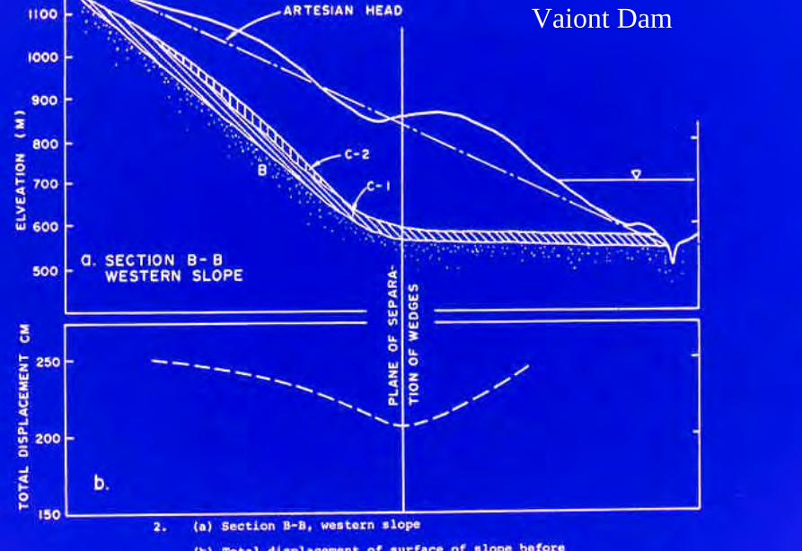
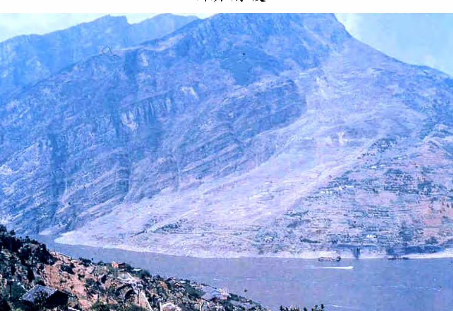
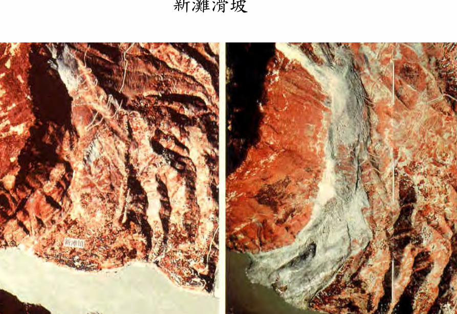
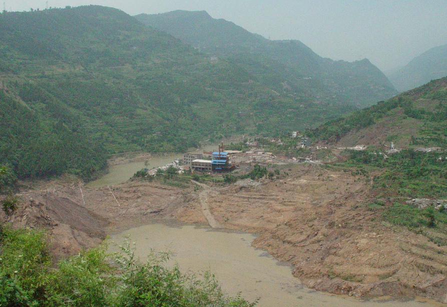
TGP Layout
TGP Layout
TGP Shiplock
TGP Shi l k
TGP Shiplock Section
TGP Shiplock Section
TGP Rock Core
TGP Rock Core
Man Wan Dam
Man Wan Landslide Site
The landslide of the Manwan Hydropower ProjectJanuary 8 1989
云南小湾水电站左岸坝前边坡
开挖时面貌
湖南五強溪水庫滑坡
Da Lake
Xiao Lake
Yinping dam
Rockfallsource
Da Lake
四川大渡河滑坡壩(1933年大地震)
MUDFLOW OF THE LONGYANGXIA POWER STATION
Time of occurrenceAugust 4 of 1997 at 2355
Cause of the incidentA 2-hour constant rainfall with a total precipitation of 55 mm
Source of the mudflow material Natural deposit and construction waste in the Beidagou Gully
龙羊峡水电站128万千瓦
Geotechnical Issues (E) Tunnels and Excavations in Rock
- Fracture-induced instability (rock mass
classification and tunnel support design) - Stress-induced instability - Time-dependent deformation (eg Niagara vs
Three Gorges shiplocks)
Hoover Dam
Hoover Dam
廣州抽水蓄能電站
Two Types of Instability Underground
bull Stress ndash controlledbull Fracture - controlled
Rock Mass Classifications
bull Rock Quality Designation (RQD)
bull Rock Mass Rating System (RMR)
bull Rock Tunnelling Quality Index (Q)
Class Qualitative description BQ Value
I Hard rock intact gt 550
II Hard rock relatively intactRelatively hard rock intact
550 ~ 451
III Hard rock relatively fracturedRelatively hard or interlayered of hard and weak rock relatively
intactRelatively weak rock intact
450 ~ 351
IV Hard rock fracturedRelatively hard rock fractured-relatively fracturedRelatively weak rock or interlayered of weak and hard rock with dominant
weak rock relatively intact or relatively fracturedWeak rock intact or relatively intact
350 ~ 251
V Relatively weak rock fracturedWeak rock fractured-relatively fracturedExtremely weak rock extremely fractured
lt 250
National Standard for Engineering Classification of Rock Masses (GB 50218-94)
Table 1 Basic quality (BQ) of rock mass
BQ = 90 + 3 Rc + 250 Kv
where Rc = uniaxial compressive strength (MPa)Kv = intactness index of rock mass
Table 2 Classification based on uniaxial compressive strength Rc
Rc (MPa) gt 60 60 ~ 30 30 ~ 15 15 ~ 5 lt 5
Description Hard rock Relatively hard rock
Relatively weak rock
Weak rock Extremely weak rock
Table 4 Intactness Factor Kv as a function of Joint Index Jv
Jv (number of joints
m3)
lt 3 3 ~ 10 10 ~ 20 20 ~ 35 gt 35
Kv gt 075 075 ~ 055 055 ~ 035 035 ~ 015 lt 015
Kv =
Vpm= in-situ velocity of longitudinal elastic wave (kms)
Vpr = velocity of longitudinal elastic wave in intact rock (kms)
2
pt
pm
VV
⎟⎟⎠
⎞⎜⎜⎝
⎛
For engineering classification use [BQ] amended for groundwater joint orientation and in-situ stress conditions
[BQ] = BQ ndash 100 (K1 + K2 + K3)
where BQ = basic quality
K1 = correction factor for groundwater
K2 = correction factor for orientation of planes of weakness
K3 = correction factor for in-situ stress conditions
Table 5 K1 values - Correction factor for groundwater conditions
gt450 450 ~ 351 350 ~251 lt250
Wet or drops 0 01 02 ~ 03 04 ~ 06
Shower or flowP lt 01 MPa
Q lt 10 L min m
01 02 ~ 03 04 ~ 06 07 ~ 09
Shower or flowP lt01 MPa
Q lt 10 L min m
02 10
BQK1
Groundwaterinflow
Table 6 K2 values - Correction factor for orientation of planes of weakness
Relation of structure plane to tunnel axis
α lt 30 o= 30 o ~ 75 o
α gt 30 oβ gt 75 o
Other combinations
K2 04 ~ 06 0 ~ 02 02 ~ 04
α - angle between strike of structure plane and tunnel axisβ - dipping angle of structure plane
Table 7 K3 values - Correction factor for in-situ stress conditions
gt 550 550 ~ 351 450 ~ 351 350 ~251 lt 250
Extremely high stress
10 10 10 ~ 15 10 ~ 15 10
High stress 05 05 05 05 ~ 10 05 ~ 10
BQK3
Initialstress state
Technical Specifications for Water Resources and Hydropower ProjectsRock Mass Rating for Tunnelling Projects
Rock class
Rock stability Host rock
rating
StrengthStress S Support type
I Stable long termstability generally no unstable block
100 ~ 85 gt 4 No support or locally bolting or thin shotcreting in case of large span systematic shotcrete bolt and meshII Basically stable no
plasticity deformation85 ~ 65 gt 4
if S lt 4go to III
III Poor stability locally plasticity deformation or collapse
65 ~ 45 gt 2if S lt 2go to IV
Systematic shotcrete bolt and mesh if span = 20 ~ 25 m concrete lining is needed
IV Unstable short self-standing time large scale collapse
45 ~ 25 gt 2if S lt 2go to V
Systematic shotcrete bolt and mesh and concrete lining
V Extremely unstable severe collapse
lt 25 No limits
Host rock rating (HRR) = A + B + C + D + E(somewhat similar to Bieniawskirsquos RMR)
Rating on rock strength (A)
Type of rock materialHard rock Weak rock
Hard rock Moderately hard rock
Relatively weak rock
Weak rock
Uniaxial strength of saturated rock (MPa)
100 ~ 60 60 ~ 30 30 ~ 15 15 ~ 5
Rating (A)Hard rock 30 ~ 20 20 ~ 10
Weak rock 10 ~ 5 5 ~ 0
For uniaxial strength σc gt 100 MPa rock mass rating is 30
Rating on rock intactness (B)
Intactness Intact Relatively intact
Poor intactness
Relatively fractured
Fractured
Intactness factor Kv 10 ~ 075 075 ~ 055 055 ~ 035 035 ~ 015 lt 015
Hard rock 40 ~ 30 30 ~ 22 22 ~ 14 14 ~ 6 lt 6
Weak rock 25 ~ 19 19 ~ 14 14 ~ 9 9 ~ 4 lt 4
Rating (B)
Rating on state of structure planes (C)
Aperture (mm) Filling Roughness evenness Hard rock Relatively weak rock Weak rock
Closed lt 05Undulating rough 27 27 18
Planar smooth 21 21 14
Slight open 05 ~ 50
No filling Undulating rough 24 24 17Undulating smooth or
planar rough21 21 14
Planar smooth 15 15 8
Slacks
Undulating rough 21 21 14
Undulating smooth or planar rough
17 17 11
Planar smooth 12 12 8
Mud
Undulating rough 15 15 10
Undulating smooth or planar rough
12 12 8
Open gt 50
Planar smooth 9 9 6
Slacks 12 12 8Mud 6 6 4
For a length of structure plane which is less than 3 m in hard rock and relatively weak rock rating would increase by 3 for weak rock rating would increase by 2 For length gt 10 m decrease rating by 3 and 2 respectively for hard rock and relatively weak rock If aperture gt 10 m without filling rating is 0
Rating on groundwater condition (D)
Basic rating(A + B + C)
State Wet Drops Linear Flow Flow
Quantity of flow
(Lminm)
lt 25or
lt 10
25-125or
10-100
gt 125or
gt 100
Water head(m)
100-85
Rating on Groundwater Conditions
(D)
0 0 -2 ~ -6
85-65 0 ~ -2 0 ~ -2 -6 ~ -10
65-45 -2 ~ -6 -2 ~ -6 -10 ~ -14
45 ~ 25 -6 ~ -10 -10 ~ -14 -14 ~ -18
lt 25 -10 ~ -14 -14 ~ -18 -18 ~ -20
Rating on orientation of structure planes (E)
Angle betweenstrike of
structure planeand tunnel axis
( o )
90o ~ 60o 60o ~ 30o lt 30o
Dipping angle( o )
gt70 75~45 45~20 lt20 gt70 75~45 45~20 45~20
Crown -2
Wall -5
-5
-2
-12-10-10
0 -2 -5
-5
-10
lt20 gt70 70~45 lt20
0 -2 -12
0
-12-10
-12 0
-5
-2 -5 -10
Rating (E)
Factor Basis for Rating Rating
Saturated Compressive Strength (MPa) gt100 100-60 60-30 30-15 15-5
Rating for A gt30 30-20 20-10 10-5 5-0
Intactness Coefficient 10-075 075-055 055-035 035-015 lt015
σc gt 30 MPa 40-30 30-22 22-14 14-5 lt6
σc lt 30 MPa
Degree of openness
Infillings
Polishness of surface
σc gt 60 MPa
σc 60 - 30 MPa 27-21 24-15 21-12 15-9 12-6
18-14 17-8 14-8 10-6 8-4
gt10m
-3
-2
100-85
σc lt 30 MPa
70o- 45o 45o- 20o lt20o
-5 -10
0-2
-2
-5
σc gt 60 MPa
σc lt 60 MPa
Seeping dripping 0
Linear flow 0 rarr -2
-2 rarr -6
90o - 60o
gt70o
Roof 0
Sidewall -2
Gush of water
25-19 19-14 14-9 9-4 lt4
Closed lt05mm
Slightly open 05 ndash 50 mm Open gt 5 mm
Nil Rock fragments
Clay Fragmented Clay
Flat polished to curved rough
27-21 24-15 21-12 15-9 12-6
Length of structural surface lt3 m 3-10 m
+3 0
+2 0
A + B + C1 + C2 Rating 85-65 64-45 45-25 lt25
0 rarr -2 -2 rarr -6 -6 rarr -10 -10 rarr -14
-2 rarr -6 -6 rarr -10 -10 rarr -14 -14 rarr -18
-6 rarr -10 -10 rarr -14 -14 rarr -18 -18 rarr -20
Angle between tunnel alignment and structural orientation (strike)
60o - 30o lt 30o
Dip of structural orientation gt 70o 70o - 4 5o 45o - 20o lt 20o gt 70o 70o - 45o 45o - 20o lt 20o
2 -5 -10 -12 -5 -10 -12 -12
-5 -10 -2 0 -10 -12 -5 0
Rating for E
E
Rating for D
D
Rating for C2
C2
Rating for C1
Structural surface condition
C1
Rating for B
B
A
Host Rock Rating (HRR)
Recommended rock parameters
Class Gravity density γ(kNm3)
Friction angle ϕ (o)
Cohesion C(MPa)
Deformation module E(MPa)
Poisson ratio ν
I gt 60 gt 21 gt 33 lt 02
II 60 ~ 50 21 ~ 15 33 ~ 20 02 ~ 025
III 265 ~ 245 50 ~ 39 15 ~ 07 20 ~ 6 025 ~ 03
IV 245 ~ 225 39 ~ 27 07 ~ 02 6 ~ 13 03 ~ 035
V lt 225 lt 27 lt 02 lt 13 gt 035
gt 265
Recommended rock strength parameters
ClassConcrete-rock contact Rock mass Deformation
modulus
fprime cprime (MPa) fprime cprime (MPa) E0 X 104 (MPa)
I 15 ~ 13 15 ~ 13 16 ~ 14 25 ~ 20 gt 20
II 13 ~ 11 13 ~ 11 14 ~ 12 20 ~ 15 20 ~ 10
III 11 ~ 09 11 ~ 07 12 ~ 08 15 ~ 07 10 ~ 05
IV 09 ~ 07 07 ~ 03 08 ~ 055 07 ~ 03 05 ~ 02
V 07 ~ 04 03 ~ 005 055 ~ 040 03 ~ 005 02 ~ 002
fprime cprime - Shear strength
Design Applications of HRR
Rock PropertiesRock Type
Rock Mass Stability Host Rock
Rating (HRR)
Strength vs Stress Ratio (S) f C (MPa) E(x 104MPa)
Support Requirements
I Stable with long-term stability no unstable blocks in general
100 - 85 16 - 14 25 - 20 gt 20 Unsupported or localized boltsshotcrete or thin shotcrete add wire mesh for tunnels with large span
II Essentially stable with overall stability no plastic deformation localized rockfall
85 - 65 Downgrade to III for S lt 4
14 - 12 20 - 15 20 - 10
III Poor stability localized plastic deformation cave-in if unsupported temporarily stable in intact relatively soft rock
65 - 45 Downgrade to IV for S lt 2
12 - 08 15 - 07 10 - 05 Bolts and shotcrete with wire mesh concrete lining for tunnel span of 20 -25 m
IV Unstable very short standup time relatively large deformationfailure may occur
45 - 25 Downgrade to V for S lt 1
08 - 055 07 - 03 05 - 02 Bolts and shotcrete with re-bar mesh and concrete lining
V Very unstable could not stand up severe deformationfailure
lt 25 055 - 040 03 - 005 02 - 002
SUPPORT PARAMETERS(National Standard for Design of Bolt-shotcrete Support)
Span (m)Rock Class
B lt 5 m 5 lt B lt 10 10 lt B lt 20 15 lt B lt 20 20 lt B lt 25 m
I No support Shotcrete50 mm
(1) Shotcrete 80-100 mm(2) Shotcrete 50 mmbolt 20-25 m
Shotcrete Shotcrete 120-150 mmwith mesh bolt 30-40 m
II Shotcrete50 mm
(1) Shotcrete 80-100 mm(2) Shotcrete 50 mmbolt 15-2m
(1) Shotcrete 120-150 mm mesh if necessary(2) Shotcrete 80-120 mmbolt 2-3 m mesh if necessary
Shotcrete 120-150 mmmesh bolt 25-30 m
Shotcrete 150-200 mmmesh bolt 3-4 m
III (1) Shotcrete 80-100 mm(2) Shotcrete 50 mmbolt 15-2 m
(1) Shotcrete 120-150 mm mesh if necessary(2) Shotcrete 80-120 mmbolt 2-3 m mesh if necessary
Shotcrete 100-150 mmmesh bolt 20-30 m
Shotcrete 150-200 mmmesh bolt 3-4 m
IV Shotcrete 80-100 mmbolt 15-20 m
Shotcrete 100-200 mmmesh bolt 20-25 m bottom arch if necessary
Shotcrete 150-200 mmmesh bolt 25-30 m bottom arch if necessary
V Shotcrete 120-150 mmmesh bolt 15-20 m bottom arch if necessary
Shotcrete 150-200 mmmesh bolt 20-30 m bottom frame if necessary
GB-J86-85 (Revised)
Comparison of Rock Mass Classification Systems
System Range of Classes
Main Factors
Q 001-1000
9 RQD Jn (joint set number) Jr (joint roughness number) Ja (joint alteration number) Stress reduction factor SRF
RMR 0-100 5 Rock strength RQD Spacing conditions and orientation of joints Groundwater
HRR 0-100 5 Rock strength Intactness Conditions and Orientation of Weakness Planes Groundwater Initial Stresses
BQ lt 250-gt 500
5 Rock strength Intactness Groundwater Orientation of Weakness Planes Initial Stresses
Important Factors that are common among the various systems
1 Rock strength
2 Intactness
3 Condition of planes of weakness
4 Groundwater
5 Orientation of discontinuities
6 Initial stresses
Support systems for underground excavations in ChinaRock Class Span (m) Shotcrete Steel Mesh Bolt Concrete Lining
Total Number
of Projects
Thickness (cm)
Diameters(mm)
Spacing (m)
Diameter (mm)
Length (m)
Spacing (m)
Thickness(cm)
Number of Works
I 5-10 3-15 no no 18-22 12-30 Random no 9
10-15 3-20 6-12 025-15 18-22 15-35 10-15 no 9
15-20 10-20 no no 20-22 10-30 10-15 no 3
II 5-10 5-15 6-10 02-13 16-20 12-21 10-12 no 2 10
10-15 4-20 6-18 02-13 18-22 15-35 08-15 30-50 13
15-20 8-16 8-12 02-13 16-32 20-40 12-15 no 10
III 5-10 5-20 6-10 02-10 18-22 16-30 10-15 wall 1 12
10-15 5-20 5-12 02-10 16-24 15-35 10-15 11
15-20 10-16 6-12 02-08 16-30 20-40 08-12 8
IV 5-10 15-20 6-14 02-025 18-22 18-40 075-125 40 4 10
10-15 5-20 6-12 02-03 16-22 25-40 08-125 50 2 5
15-20 20 10-19 025 22 20 12 1
V 5-10 10-15 8-14 02-025 16-22 15-36 08-12 40 2
4
7
10-15 18-20 6-12 02-03 20-22 25-35 08-10 60 4
Three Gorges ProjectAmended [BQ] Values for Granite
Maximum [BQ]max = 630
Minimum [BQ]min = 500
Average [BQ]mean = 565
Class I- to II+
Guangzhou Pumped Storage Project
bull Location north of Guangzhou Guangdong Province
bull Underground Powerhouse
1465 m x 22 m x 445 m (L x W x H)
at 330 - 400 m depth completed in 1993
bull Host Rock Biotite granite
bull Support System Bolts (at 2 x 15 m spacing)+ 15 cm shotcrete in both crown and
sidewalls
Xiaolangdi Project
bull Location on Yellow River Henan Provincebull Underground Powerhouse
2515 m x 262 m x 614m (L x W x H)At 70 ndash 100 m depth completed in 1999
bull Host Rock Sandstone with argillaceous bedsbull Support System Bolts (at 15 spacing) with wiremesh
and shotcret (20 cm) in crownBolts (at 15 spacing) in sidewallsAnchors locally where required
Xiaolangdi Project on Yellow RiverProposed support parameters in design stage
Support DesignCavern Type Location Rock Type
Rock Grade Tensile Bolt Re Shotcrete
Top T14 III Φ 25 15 X 15 m (mortar bolt)
L = 53 m (alternatively)Φ 6 20 X 20 cmδ = 10 cm (C20)
Tailrace Cavern
Top T14 III Φ 28 15 X 15 m
L = 84 m (alternatively)Φ 8 20 X 20 cmδ = 20 cm (C20)
Sidewall T14
T13-2
III Φ 25 15 X 15 mL = 128 m (alternatively)
Φ 8 20 X 20 cmδ = 15 cm (C20)
Top T14 II- Φ 25 15 X 15 m
L = 73 m (alternatively)Φ 6 20 X 20 cmδ = 15 cm (C20)
Sidewall T14 II- Φ 25 15 X 15 m
L = 53 m (alternatively)Φ 6 20 X 20 cmδ = 10 cm (C20)
Sidewall T14 III Φ 25 15 X 15 m (mortar bolt)
L = 4 mΦ 6 25 X 25 cmδ = 10 cm (C20)
Transformer Cavern
Main Power-house
T14 thick to massive siliceous fine-grained sandstone
T13-2 thick to massive argillaceous and calcareous silty fine-grained sandstone
Xiaolangdi Project on Yellow RiverActual support used at construction stage
Support DesignCavern Type Location Rock Type
Rock Grade Tensile Bolt Re Shotcrete
Support Pres
(MPa)0112
0056
0104
0104
056
0044
Top T14 III Φ 32 3 X 3 m L = 5 m P = 150 KN
Φ 32 3 X 3 m L = 3 m P = 150 KNΦ 6 25 X 25 cmδ = 15 cm (C20)
Tailrace Cavern
Top T14 III Φ 32 3 X 3 m L = 8 m P = 150 KN
Φ 32 3 X 3 m L = 6 m P = 150 KNCable L = 25 m 45 X 6 m P = 1500 KN
Φ 8 20 X 20 cmδ = 20 cm (C20)
Sidewall T14
T13-2
III Φ 32 3 X 3 m L = 10 m P = 150 KNΦ 32 3 X 3 m L = 6 m P = 150 KNTwo rows of pre-stressed bolt added for argillized interlayers 500 KN L = 15 m
Φ 8 20 X 20 cmδ = 20 cm (C20)
Top T14 II- Φ 32 24 X 24 m L = 8 m P = 150 KN
Φ 32 24 X 24 m L = 4 m P = 150 KNΦ 6 20 X 20 cmδ = 20 cm (C20)
Sidewall T14 II- Φ 32 24 X 24 m L = 6 m P = 150 KN
Φ 32 24 X 24 m L = 4 m P = 150 KNΦ 6 25 X 25 cmδ = 15 cm (C20)
Sidewall T14 III Φ 32 15 X 15 m
L = 4 m P = 100 KNΦ 6 25 X 25 cmδ = 10 cm (C20)
Transformer Cavern
Main Power-house
Er Tan Dam
Er Tan Dam
Er Tan Dam Layout
Er Tan Dam Layout
Er Tan Under Construction
Er Tan Under Construction
Er Tan Underground Power House
Er Tan Underground Power House
Er Tan Diversion Tunnel
Er Tan Diversion Tunnel
Er Tan Rock Discing
Er Tan Rock Discing
Er Tan Geostress
Er Tan Geostress(kgcm2)
Strain Energy Approach to Modelling Rock Squeeze Problems
For a virtual displacement δ e
Work Done = Force x Displacement = Feδ e = (δ e)TFe
where Fe = corresponding nodal force Strain energy recovered from unit volume of rock = Stress x Strain = σ ε = ε Tσ = ([B] δ e)T ([D]ε ) = (δ e)T[B][D] ε Work Done = Strain Energy Released (δ e)TFe = (δ e)T int vol [B]T[D] ε dv
or Fe = int vol [B]T[D] ε dv
Some Features of Chinese Hydro Projects
bull Same design framework as in the Westbull Very detailed site investigationsbull Including numerous aditsbull Sometimes leads to significant cost savingsbull (eg Ertan dam allowed to be founded on Class III
rock instead of Class II as called for by Design Standard
bull Strong emphasis on geology and rock mass structure studies
bull Very detailed analysis including numerical modelling AI etc
青海龍羊峽
青海 黃河 李家峽 拱壩壩址
青海 李家峽
探洞
滑面
滑面
李家峽水庫 老滑坡體
剖面
電力需求增長
水電資源
Schematic Map of Hydropower Stations of 1GW and above in Operation or Under Construction
Jin Sha River Hydro Power
南水北調三線
Method of Generation Pros Cons
Capital Construction Cost
(Ratio) Fuel Cost
Fossil
bull Short construction period (2-3 years)
bull Easy to start up
bull Air pollution bull Ashsludge
disposal 1 Relatively high
Hydraulic
bull Longer construction period (gt 5 years)
bull Resettlement of affected population
bull Preservation of cultural amp historic relics
2
Nuclear
bull Relatively long construction period (ge 10 years)
bull Nuclear safety concern
bull Nuclear waste disposal needs
5 Relatively low
Other generation methods solar wind biomass etc
The Joy of being a Hydro Project Engineer
bull Free helicopter jet rides(safe most of the time)
bull Exotic places with breathtaking scenerysceneryand colorful folklore(no tourists around no phone calls etc)
攔路酒(四川 涼山)
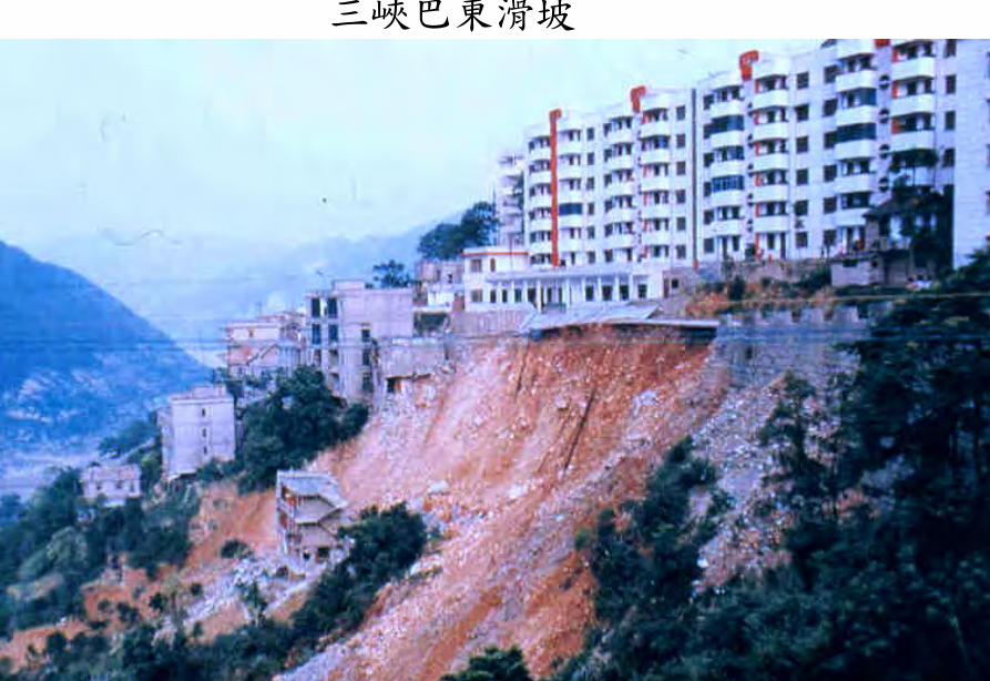
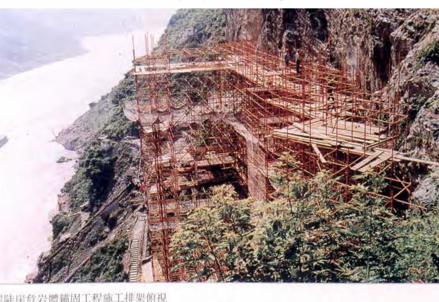
TGP Shiplock Section
TGP Shiplock Section
TGP Rock Core
TGP Rock Core
Man Wan Dam
Man Wan Landslide Site
The landslide of the Manwan Hydropower ProjectJanuary 8 1989
云南小湾水电站左岸坝前边坡
开挖时面貌
湖南五強溪水庫滑坡
Da Lake
Xiao Lake
Yinping dam
Rockfallsource
Da Lake
四川大渡河滑坡壩(1933年大地震)
MUDFLOW OF THE LONGYANGXIA POWER STATION
Time of occurrenceAugust 4 of 1997 at 2355
Cause of the incidentA 2-hour constant rainfall with a total precipitation of 55 mm
Source of the mudflow material Natural deposit and construction waste in the Beidagou Gully
龙羊峡水电站128万千瓦
Geotechnical Issues (E) Tunnels and Excavations in Rock
- Fracture-induced instability (rock mass
classification and tunnel support design) - Stress-induced instability - Time-dependent deformation (eg Niagara vs
Three Gorges shiplocks)
Hoover Dam
Hoover Dam
廣州抽水蓄能電站
Two Types of Instability Underground
bull Stress ndash controlledbull Fracture - controlled
Rock Mass Classifications
bull Rock Quality Designation (RQD)
bull Rock Mass Rating System (RMR)
bull Rock Tunnelling Quality Index (Q)
Class Qualitative description BQ Value
I Hard rock intact gt 550
II Hard rock relatively intactRelatively hard rock intact
550 ~ 451
III Hard rock relatively fracturedRelatively hard or interlayered of hard and weak rock relatively
intactRelatively weak rock intact
450 ~ 351
IV Hard rock fracturedRelatively hard rock fractured-relatively fracturedRelatively weak rock or interlayered of weak and hard rock with dominant
weak rock relatively intact or relatively fracturedWeak rock intact or relatively intact
350 ~ 251
V Relatively weak rock fracturedWeak rock fractured-relatively fracturedExtremely weak rock extremely fractured
lt 250
National Standard for Engineering Classification of Rock Masses (GB 50218-94)
Table 1 Basic quality (BQ) of rock mass
BQ = 90 + 3 Rc + 250 Kv
where Rc = uniaxial compressive strength (MPa)Kv = intactness index of rock mass
Table 2 Classification based on uniaxial compressive strength Rc
Rc (MPa) gt 60 60 ~ 30 30 ~ 15 15 ~ 5 lt 5
Description Hard rock Relatively hard rock
Relatively weak rock
Weak rock Extremely weak rock
Table 4 Intactness Factor Kv as a function of Joint Index Jv
Jv (number of joints
m3)
lt 3 3 ~ 10 10 ~ 20 20 ~ 35 gt 35
Kv gt 075 075 ~ 055 055 ~ 035 035 ~ 015 lt 015
Kv =
Vpm= in-situ velocity of longitudinal elastic wave (kms)
Vpr = velocity of longitudinal elastic wave in intact rock (kms)
2
pt
pm
VV
⎟⎟⎠
⎞⎜⎜⎝
⎛
For engineering classification use [BQ] amended for groundwater joint orientation and in-situ stress conditions
[BQ] = BQ ndash 100 (K1 + K2 + K3)
where BQ = basic quality
K1 = correction factor for groundwater
K2 = correction factor for orientation of planes of weakness
K3 = correction factor for in-situ stress conditions
Table 5 K1 values - Correction factor for groundwater conditions
gt450 450 ~ 351 350 ~251 lt250
Wet or drops 0 01 02 ~ 03 04 ~ 06
Shower or flowP lt 01 MPa
Q lt 10 L min m
01 02 ~ 03 04 ~ 06 07 ~ 09
Shower or flowP lt01 MPa
Q lt 10 L min m
02 10
BQK1
Groundwaterinflow
Table 6 K2 values - Correction factor for orientation of planes of weakness
Relation of structure plane to tunnel axis
α lt 30 o= 30 o ~ 75 o
α gt 30 oβ gt 75 o
Other combinations
K2 04 ~ 06 0 ~ 02 02 ~ 04
α - angle between strike of structure plane and tunnel axisβ - dipping angle of structure plane
Table 7 K3 values - Correction factor for in-situ stress conditions
gt 550 550 ~ 351 450 ~ 351 350 ~251 lt 250
Extremely high stress
10 10 10 ~ 15 10 ~ 15 10
High stress 05 05 05 05 ~ 10 05 ~ 10
BQK3
Initialstress state
Technical Specifications for Water Resources and Hydropower ProjectsRock Mass Rating for Tunnelling Projects
Rock class
Rock stability Host rock
rating
StrengthStress S Support type
I Stable long termstability generally no unstable block
100 ~ 85 gt 4 No support or locally bolting or thin shotcreting in case of large span systematic shotcrete bolt and meshII Basically stable no
plasticity deformation85 ~ 65 gt 4
if S lt 4go to III
III Poor stability locally plasticity deformation or collapse
65 ~ 45 gt 2if S lt 2go to IV
Systematic shotcrete bolt and mesh if span = 20 ~ 25 m concrete lining is needed
IV Unstable short self-standing time large scale collapse
45 ~ 25 gt 2if S lt 2go to V
Systematic shotcrete bolt and mesh and concrete lining
V Extremely unstable severe collapse
lt 25 No limits
Host rock rating (HRR) = A + B + C + D + E(somewhat similar to Bieniawskirsquos RMR)
Rating on rock strength (A)
Type of rock materialHard rock Weak rock
Hard rock Moderately hard rock
Relatively weak rock
Weak rock
Uniaxial strength of saturated rock (MPa)
100 ~ 60 60 ~ 30 30 ~ 15 15 ~ 5
Rating (A)Hard rock 30 ~ 20 20 ~ 10
Weak rock 10 ~ 5 5 ~ 0
For uniaxial strength σc gt 100 MPa rock mass rating is 30
Rating on rock intactness (B)
Intactness Intact Relatively intact
Poor intactness
Relatively fractured
Fractured
Intactness factor Kv 10 ~ 075 075 ~ 055 055 ~ 035 035 ~ 015 lt 015
Hard rock 40 ~ 30 30 ~ 22 22 ~ 14 14 ~ 6 lt 6
Weak rock 25 ~ 19 19 ~ 14 14 ~ 9 9 ~ 4 lt 4
Rating (B)
Rating on state of structure planes (C)
Aperture (mm) Filling Roughness evenness Hard rock Relatively weak rock Weak rock
Closed lt 05Undulating rough 27 27 18
Planar smooth 21 21 14
Slight open 05 ~ 50
No filling Undulating rough 24 24 17Undulating smooth or
planar rough21 21 14
Planar smooth 15 15 8
Slacks
Undulating rough 21 21 14
Undulating smooth or planar rough
17 17 11
Planar smooth 12 12 8
Mud
Undulating rough 15 15 10
Undulating smooth or planar rough
12 12 8
Open gt 50
Planar smooth 9 9 6
Slacks 12 12 8Mud 6 6 4
For a length of structure plane which is less than 3 m in hard rock and relatively weak rock rating would increase by 3 for weak rock rating would increase by 2 For length gt 10 m decrease rating by 3 and 2 respectively for hard rock and relatively weak rock If aperture gt 10 m without filling rating is 0
Rating on groundwater condition (D)
Basic rating(A + B + C)
State Wet Drops Linear Flow Flow
Quantity of flow
(Lminm)
lt 25or
lt 10
25-125or
10-100
gt 125or
gt 100
Water head(m)
100-85
Rating on Groundwater Conditions
(D)
0 0 -2 ~ -6
85-65 0 ~ -2 0 ~ -2 -6 ~ -10
65-45 -2 ~ -6 -2 ~ -6 -10 ~ -14
45 ~ 25 -6 ~ -10 -10 ~ -14 -14 ~ -18
lt 25 -10 ~ -14 -14 ~ -18 -18 ~ -20
Rating on orientation of structure planes (E)
Angle betweenstrike of
structure planeand tunnel axis
( o )
90o ~ 60o 60o ~ 30o lt 30o
Dipping angle( o )
gt70 75~45 45~20 lt20 gt70 75~45 45~20 45~20
Crown -2
Wall -5
-5
-2
-12-10-10
0 -2 -5
-5
-10
lt20 gt70 70~45 lt20
0 -2 -12
0
-12-10
-12 0
-5
-2 -5 -10
Rating (E)
Factor Basis for Rating Rating
Saturated Compressive Strength (MPa) gt100 100-60 60-30 30-15 15-5
Rating for A gt30 30-20 20-10 10-5 5-0
Intactness Coefficient 10-075 075-055 055-035 035-015 lt015
σc gt 30 MPa 40-30 30-22 22-14 14-5 lt6
σc lt 30 MPa
Degree of openness
Infillings
Polishness of surface
σc gt 60 MPa
σc 60 - 30 MPa 27-21 24-15 21-12 15-9 12-6
18-14 17-8 14-8 10-6 8-4
gt10m
-3
-2
100-85
σc lt 30 MPa
70o- 45o 45o- 20o lt20o
-5 -10
0-2
-2
-5
σc gt 60 MPa
σc lt 60 MPa
Seeping dripping 0
Linear flow 0 rarr -2
-2 rarr -6
90o - 60o
gt70o
Roof 0
Sidewall -2
Gush of water
25-19 19-14 14-9 9-4 lt4
Closed lt05mm
Slightly open 05 ndash 50 mm Open gt 5 mm
Nil Rock fragments
Clay Fragmented Clay
Flat polished to curved rough
27-21 24-15 21-12 15-9 12-6
Length of structural surface lt3 m 3-10 m
+3 0
+2 0
A + B + C1 + C2 Rating 85-65 64-45 45-25 lt25
0 rarr -2 -2 rarr -6 -6 rarr -10 -10 rarr -14
-2 rarr -6 -6 rarr -10 -10 rarr -14 -14 rarr -18
-6 rarr -10 -10 rarr -14 -14 rarr -18 -18 rarr -20
Angle between tunnel alignment and structural orientation (strike)
60o - 30o lt 30o
Dip of structural orientation gt 70o 70o - 4 5o 45o - 20o lt 20o gt 70o 70o - 45o 45o - 20o lt 20o
2 -5 -10 -12 -5 -10 -12 -12
-5 -10 -2 0 -10 -12 -5 0
Rating for E
E
Rating for D
D
Rating for C2
C2
Rating for C1
Structural surface condition
C1
Rating for B
B
A
Host Rock Rating (HRR)
Recommended rock parameters
Class Gravity density γ(kNm3)
Friction angle ϕ (o)
Cohesion C(MPa)
Deformation module E(MPa)
Poisson ratio ν
I gt 60 gt 21 gt 33 lt 02
II 60 ~ 50 21 ~ 15 33 ~ 20 02 ~ 025
III 265 ~ 245 50 ~ 39 15 ~ 07 20 ~ 6 025 ~ 03
IV 245 ~ 225 39 ~ 27 07 ~ 02 6 ~ 13 03 ~ 035
V lt 225 lt 27 lt 02 lt 13 gt 035
gt 265
Recommended rock strength parameters
ClassConcrete-rock contact Rock mass Deformation
modulus
fprime cprime (MPa) fprime cprime (MPa) E0 X 104 (MPa)
I 15 ~ 13 15 ~ 13 16 ~ 14 25 ~ 20 gt 20
II 13 ~ 11 13 ~ 11 14 ~ 12 20 ~ 15 20 ~ 10
III 11 ~ 09 11 ~ 07 12 ~ 08 15 ~ 07 10 ~ 05
IV 09 ~ 07 07 ~ 03 08 ~ 055 07 ~ 03 05 ~ 02
V 07 ~ 04 03 ~ 005 055 ~ 040 03 ~ 005 02 ~ 002
fprime cprime - Shear strength
Design Applications of HRR
Rock PropertiesRock Type
Rock Mass Stability Host Rock
Rating (HRR)
Strength vs Stress Ratio (S) f C (MPa) E(x 104MPa)
Support Requirements
I Stable with long-term stability no unstable blocks in general
100 - 85 16 - 14 25 - 20 gt 20 Unsupported or localized boltsshotcrete or thin shotcrete add wire mesh for tunnels with large span
II Essentially stable with overall stability no plastic deformation localized rockfall
85 - 65 Downgrade to III for S lt 4
14 - 12 20 - 15 20 - 10
III Poor stability localized plastic deformation cave-in if unsupported temporarily stable in intact relatively soft rock
65 - 45 Downgrade to IV for S lt 2
12 - 08 15 - 07 10 - 05 Bolts and shotcrete with wire mesh concrete lining for tunnel span of 20 -25 m
IV Unstable very short standup time relatively large deformationfailure may occur
45 - 25 Downgrade to V for S lt 1
08 - 055 07 - 03 05 - 02 Bolts and shotcrete with re-bar mesh and concrete lining
V Very unstable could not stand up severe deformationfailure
lt 25 055 - 040 03 - 005 02 - 002
SUPPORT PARAMETERS(National Standard for Design of Bolt-shotcrete Support)
Span (m)Rock Class
B lt 5 m 5 lt B lt 10 10 lt B lt 20 15 lt B lt 20 20 lt B lt 25 m
I No support Shotcrete50 mm
(1) Shotcrete 80-100 mm(2) Shotcrete 50 mmbolt 20-25 m
Shotcrete Shotcrete 120-150 mmwith mesh bolt 30-40 m
II Shotcrete50 mm
(1) Shotcrete 80-100 mm(2) Shotcrete 50 mmbolt 15-2m
(1) Shotcrete 120-150 mm mesh if necessary(2) Shotcrete 80-120 mmbolt 2-3 m mesh if necessary
Shotcrete 120-150 mmmesh bolt 25-30 m
Shotcrete 150-200 mmmesh bolt 3-4 m
III (1) Shotcrete 80-100 mm(2) Shotcrete 50 mmbolt 15-2 m
(1) Shotcrete 120-150 mm mesh if necessary(2) Shotcrete 80-120 mmbolt 2-3 m mesh if necessary
Shotcrete 100-150 mmmesh bolt 20-30 m
Shotcrete 150-200 mmmesh bolt 3-4 m
IV Shotcrete 80-100 mmbolt 15-20 m
Shotcrete 100-200 mmmesh bolt 20-25 m bottom arch if necessary
Shotcrete 150-200 mmmesh bolt 25-30 m bottom arch if necessary
V Shotcrete 120-150 mmmesh bolt 15-20 m bottom arch if necessary
Shotcrete 150-200 mmmesh bolt 20-30 m bottom frame if necessary
GB-J86-85 (Revised)
Comparison of Rock Mass Classification Systems
System Range of Classes
Main Factors
Q 001-1000
9 RQD Jn (joint set number) Jr (joint roughness number) Ja (joint alteration number) Stress reduction factor SRF
RMR 0-100 5 Rock strength RQD Spacing conditions and orientation of joints Groundwater
HRR 0-100 5 Rock strength Intactness Conditions and Orientation of Weakness Planes Groundwater Initial Stresses
BQ lt 250-gt 500
5 Rock strength Intactness Groundwater Orientation of Weakness Planes Initial Stresses
Important Factors that are common among the various systems
1 Rock strength
2 Intactness
3 Condition of planes of weakness
4 Groundwater
5 Orientation of discontinuities
6 Initial stresses
Support systems for underground excavations in ChinaRock Class Span (m) Shotcrete Steel Mesh Bolt Concrete Lining
Total Number
of Projects
Thickness (cm)
Diameters(mm)
Spacing (m)
Diameter (mm)
Length (m)
Spacing (m)
Thickness(cm)
Number of Works
I 5-10 3-15 no no 18-22 12-30 Random no 9
10-15 3-20 6-12 025-15 18-22 15-35 10-15 no 9
15-20 10-20 no no 20-22 10-30 10-15 no 3
II 5-10 5-15 6-10 02-13 16-20 12-21 10-12 no 2 10
10-15 4-20 6-18 02-13 18-22 15-35 08-15 30-50 13
15-20 8-16 8-12 02-13 16-32 20-40 12-15 no 10
III 5-10 5-20 6-10 02-10 18-22 16-30 10-15 wall 1 12
10-15 5-20 5-12 02-10 16-24 15-35 10-15 11
15-20 10-16 6-12 02-08 16-30 20-40 08-12 8
IV 5-10 15-20 6-14 02-025 18-22 18-40 075-125 40 4 10
10-15 5-20 6-12 02-03 16-22 25-40 08-125 50 2 5
15-20 20 10-19 025 22 20 12 1
V 5-10 10-15 8-14 02-025 16-22 15-36 08-12 40 2
4
7
10-15 18-20 6-12 02-03 20-22 25-35 08-10 60 4
Three Gorges ProjectAmended [BQ] Values for Granite
Maximum [BQ]max = 630
Minimum [BQ]min = 500
Average [BQ]mean = 565
Class I- to II+
Guangzhou Pumped Storage Project
bull Location north of Guangzhou Guangdong Province
bull Underground Powerhouse
1465 m x 22 m x 445 m (L x W x H)
at 330 - 400 m depth completed in 1993
bull Host Rock Biotite granite
bull Support System Bolts (at 2 x 15 m spacing)+ 15 cm shotcrete in both crown and
sidewalls
Xiaolangdi Project
bull Location on Yellow River Henan Provincebull Underground Powerhouse
2515 m x 262 m x 614m (L x W x H)At 70 ndash 100 m depth completed in 1999
bull Host Rock Sandstone with argillaceous bedsbull Support System Bolts (at 15 spacing) with wiremesh
and shotcret (20 cm) in crownBolts (at 15 spacing) in sidewallsAnchors locally where required
Xiaolangdi Project on Yellow RiverProposed support parameters in design stage
Support DesignCavern Type Location Rock Type
Rock Grade Tensile Bolt Re Shotcrete
Top T14 III Φ 25 15 X 15 m (mortar bolt)
L = 53 m (alternatively)Φ 6 20 X 20 cmδ = 10 cm (C20)
Tailrace Cavern
Top T14 III Φ 28 15 X 15 m
L = 84 m (alternatively)Φ 8 20 X 20 cmδ = 20 cm (C20)
Sidewall T14
T13-2
III Φ 25 15 X 15 mL = 128 m (alternatively)
Φ 8 20 X 20 cmδ = 15 cm (C20)
Top T14 II- Φ 25 15 X 15 m
L = 73 m (alternatively)Φ 6 20 X 20 cmδ = 15 cm (C20)
Sidewall T14 II- Φ 25 15 X 15 m
L = 53 m (alternatively)Φ 6 20 X 20 cmδ = 10 cm (C20)
Sidewall T14 III Φ 25 15 X 15 m (mortar bolt)
L = 4 mΦ 6 25 X 25 cmδ = 10 cm (C20)
Transformer Cavern
Main Power-house
T14 thick to massive siliceous fine-grained sandstone
T13-2 thick to massive argillaceous and calcareous silty fine-grained sandstone
Xiaolangdi Project on Yellow RiverActual support used at construction stage
Support DesignCavern Type Location Rock Type
Rock Grade Tensile Bolt Re Shotcrete
Support Pres
(MPa)0112
0056
0104
0104
056
0044
Top T14 III Φ 32 3 X 3 m L = 5 m P = 150 KN
Φ 32 3 X 3 m L = 3 m P = 150 KNΦ 6 25 X 25 cmδ = 15 cm (C20)
Tailrace Cavern
Top T14 III Φ 32 3 X 3 m L = 8 m P = 150 KN
Φ 32 3 X 3 m L = 6 m P = 150 KNCable L = 25 m 45 X 6 m P = 1500 KN
Φ 8 20 X 20 cmδ = 20 cm (C20)
Sidewall T14
T13-2
III Φ 32 3 X 3 m L = 10 m P = 150 KNΦ 32 3 X 3 m L = 6 m P = 150 KNTwo rows of pre-stressed bolt added for argillized interlayers 500 KN L = 15 m
Φ 8 20 X 20 cmδ = 20 cm (C20)
Top T14 II- Φ 32 24 X 24 m L = 8 m P = 150 KN
Φ 32 24 X 24 m L = 4 m P = 150 KNΦ 6 20 X 20 cmδ = 20 cm (C20)
Sidewall T14 II- Φ 32 24 X 24 m L = 6 m P = 150 KN
Φ 32 24 X 24 m L = 4 m P = 150 KNΦ 6 25 X 25 cmδ = 15 cm (C20)
Sidewall T14 III Φ 32 15 X 15 m
L = 4 m P = 100 KNΦ 6 25 X 25 cmδ = 10 cm (C20)
Transformer Cavern
Main Power-house
Er Tan Dam
Er Tan Dam
Er Tan Dam Layout
Er Tan Dam Layout
Er Tan Under Construction
Er Tan Under Construction
Er Tan Underground Power House
Er Tan Underground Power House
Er Tan Diversion Tunnel
Er Tan Diversion Tunnel
Er Tan Rock Discing
Er Tan Rock Discing
Er Tan Geostress
Er Tan Geostress(kgcm2)
Strain Energy Approach to Modelling Rock Squeeze Problems
For a virtual displacement δ e
Work Done = Force x Displacement = Feδ e = (δ e)TFe
where Fe = corresponding nodal force Strain energy recovered from unit volume of rock = Stress x Strain = σ ε = ε Tσ = ([B] δ e)T ([D]ε ) = (δ e)T[B][D] ε Work Done = Strain Energy Released (δ e)TFe = (δ e)T int vol [B]T[D] ε dv
or Fe = int vol [B]T[D] ε dv
Some Features of Chinese Hydro Projects
bull Same design framework as in the Westbull Very detailed site investigationsbull Including numerous aditsbull Sometimes leads to significant cost savingsbull (eg Ertan dam allowed to be founded on Class III
rock instead of Class II as called for by Design Standard
bull Strong emphasis on geology and rock mass structure studies
bull Very detailed analysis including numerical modelling AI etc
青海龍羊峽
青海 黃河 李家峽 拱壩壩址
青海 李家峽
探洞
滑面
滑面
李家峽水庫 老滑坡體
剖面
電力需求增長
水電資源
Schematic Map of Hydropower Stations of 1GW and above in Operation or Under Construction
Jin Sha River Hydro Power
南水北調三線
Method of Generation Pros Cons
Capital Construction Cost
(Ratio) Fuel Cost
Fossil
bull Short construction period (2-3 years)
bull Easy to start up
bull Air pollution bull Ashsludge
disposal 1 Relatively high
Hydraulic
bull Longer construction period (gt 5 years)
bull Resettlement of affected population
bull Preservation of cultural amp historic relics
2
Nuclear
bull Relatively long construction period (ge 10 years)
bull Nuclear safety concern
bull Nuclear waste disposal needs
5 Relatively low
Other generation methods solar wind biomass etc
The Joy of being a Hydro Project Engineer
bull Free helicopter jet rides(safe most of the time)
bull Exotic places with breathtaking scenerysceneryand colorful folklore(no tourists around no phone calls etc)
攔路酒(四川 涼山)
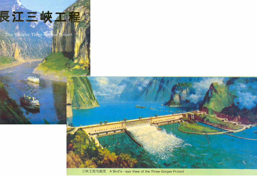
TGP Rock Core
TGP Rock Core
Man Wan Dam
Man Wan Landslide Site
The landslide of the Manwan Hydropower ProjectJanuary 8 1989
云南小湾水电站左岸坝前边坡
开挖时面貌
湖南五強溪水庫滑坡
Da Lake
Xiao Lake
Yinping dam
Rockfallsource
Da Lake
四川大渡河滑坡壩(1933年大地震)
MUDFLOW OF THE LONGYANGXIA POWER STATION
Time of occurrenceAugust 4 of 1997 at 2355
Cause of the incidentA 2-hour constant rainfall with a total precipitation of 55 mm
Source of the mudflow material Natural deposit and construction waste in the Beidagou Gully
龙羊峡水电站128万千瓦
Geotechnical Issues (E) Tunnels and Excavations in Rock
- Fracture-induced instability (rock mass
classification and tunnel support design) - Stress-induced instability - Time-dependent deformation (eg Niagara vs
Three Gorges shiplocks)
Hoover Dam
Hoover Dam
廣州抽水蓄能電站
Two Types of Instability Underground
bull Stress ndash controlledbull Fracture - controlled
Rock Mass Classifications
bull Rock Quality Designation (RQD)
bull Rock Mass Rating System (RMR)
bull Rock Tunnelling Quality Index (Q)
Class Qualitative description BQ Value
I Hard rock intact gt 550
II Hard rock relatively intactRelatively hard rock intact
550 ~ 451
III Hard rock relatively fracturedRelatively hard or interlayered of hard and weak rock relatively
intactRelatively weak rock intact
450 ~ 351
IV Hard rock fracturedRelatively hard rock fractured-relatively fracturedRelatively weak rock or interlayered of weak and hard rock with dominant
weak rock relatively intact or relatively fracturedWeak rock intact or relatively intact
350 ~ 251
V Relatively weak rock fracturedWeak rock fractured-relatively fracturedExtremely weak rock extremely fractured
lt 250
National Standard for Engineering Classification of Rock Masses (GB 50218-94)
Table 1 Basic quality (BQ) of rock mass
BQ = 90 + 3 Rc + 250 Kv
where Rc = uniaxial compressive strength (MPa)Kv = intactness index of rock mass
Table 2 Classification based on uniaxial compressive strength Rc
Rc (MPa) gt 60 60 ~ 30 30 ~ 15 15 ~ 5 lt 5
Description Hard rock Relatively hard rock
Relatively weak rock
Weak rock Extremely weak rock
Table 4 Intactness Factor Kv as a function of Joint Index Jv
Jv (number of joints
m3)
lt 3 3 ~ 10 10 ~ 20 20 ~ 35 gt 35
Kv gt 075 075 ~ 055 055 ~ 035 035 ~ 015 lt 015
Kv =
Vpm= in-situ velocity of longitudinal elastic wave (kms)
Vpr = velocity of longitudinal elastic wave in intact rock (kms)
2
pt
pm
VV
⎟⎟⎠
⎞⎜⎜⎝
⎛
For engineering classification use [BQ] amended for groundwater joint orientation and in-situ stress conditions
[BQ] = BQ ndash 100 (K1 + K2 + K3)
where BQ = basic quality
K1 = correction factor for groundwater
K2 = correction factor for orientation of planes of weakness
K3 = correction factor for in-situ stress conditions
Table 5 K1 values - Correction factor for groundwater conditions
gt450 450 ~ 351 350 ~251 lt250
Wet or drops 0 01 02 ~ 03 04 ~ 06
Shower or flowP lt 01 MPa
Q lt 10 L min m
01 02 ~ 03 04 ~ 06 07 ~ 09
Shower or flowP lt01 MPa
Q lt 10 L min m
02 10
BQK1
Groundwaterinflow
Table 6 K2 values - Correction factor for orientation of planes of weakness
Relation of structure plane to tunnel axis
α lt 30 o= 30 o ~ 75 o
α gt 30 oβ gt 75 o
Other combinations
K2 04 ~ 06 0 ~ 02 02 ~ 04
α - angle between strike of structure plane and tunnel axisβ - dipping angle of structure plane
Table 7 K3 values - Correction factor for in-situ stress conditions
gt 550 550 ~ 351 450 ~ 351 350 ~251 lt 250
Extremely high stress
10 10 10 ~ 15 10 ~ 15 10
High stress 05 05 05 05 ~ 10 05 ~ 10
BQK3
Initialstress state
Technical Specifications for Water Resources and Hydropower ProjectsRock Mass Rating for Tunnelling Projects
Rock class
Rock stability Host rock
rating
StrengthStress S Support type
I Stable long termstability generally no unstable block
100 ~ 85 gt 4 No support or locally bolting or thin shotcreting in case of large span systematic shotcrete bolt and meshII Basically stable no
plasticity deformation85 ~ 65 gt 4
if S lt 4go to III
III Poor stability locally plasticity deformation or collapse
65 ~ 45 gt 2if S lt 2go to IV
Systematic shotcrete bolt and mesh if span = 20 ~ 25 m concrete lining is needed
IV Unstable short self-standing time large scale collapse
45 ~ 25 gt 2if S lt 2go to V
Systematic shotcrete bolt and mesh and concrete lining
V Extremely unstable severe collapse
lt 25 No limits
Host rock rating (HRR) = A + B + C + D + E(somewhat similar to Bieniawskirsquos RMR)
Rating on rock strength (A)
Type of rock materialHard rock Weak rock
Hard rock Moderately hard rock
Relatively weak rock
Weak rock
Uniaxial strength of saturated rock (MPa)
100 ~ 60 60 ~ 30 30 ~ 15 15 ~ 5
Rating (A)Hard rock 30 ~ 20 20 ~ 10
Weak rock 10 ~ 5 5 ~ 0
For uniaxial strength σc gt 100 MPa rock mass rating is 30
Rating on rock intactness (B)
Intactness Intact Relatively intact
Poor intactness
Relatively fractured
Fractured
Intactness factor Kv 10 ~ 075 075 ~ 055 055 ~ 035 035 ~ 015 lt 015
Hard rock 40 ~ 30 30 ~ 22 22 ~ 14 14 ~ 6 lt 6
Weak rock 25 ~ 19 19 ~ 14 14 ~ 9 9 ~ 4 lt 4
Rating (B)
Rating on state of structure planes (C)
Aperture (mm) Filling Roughness evenness Hard rock Relatively weak rock Weak rock
Closed lt 05Undulating rough 27 27 18
Planar smooth 21 21 14
Slight open 05 ~ 50
No filling Undulating rough 24 24 17Undulating smooth or
planar rough21 21 14
Planar smooth 15 15 8
Slacks
Undulating rough 21 21 14
Undulating smooth or planar rough
17 17 11
Planar smooth 12 12 8
Mud
Undulating rough 15 15 10
Undulating smooth or planar rough
12 12 8
Open gt 50
Planar smooth 9 9 6
Slacks 12 12 8Mud 6 6 4
For a length of structure plane which is less than 3 m in hard rock and relatively weak rock rating would increase by 3 for weak rock rating would increase by 2 For length gt 10 m decrease rating by 3 and 2 respectively for hard rock and relatively weak rock If aperture gt 10 m without filling rating is 0
Rating on groundwater condition (D)
Basic rating(A + B + C)
State Wet Drops Linear Flow Flow
Quantity of flow
(Lminm)
lt 25or
lt 10
25-125or
10-100
gt 125or
gt 100
Water head(m)
100-85
Rating on Groundwater Conditions
(D)
0 0 -2 ~ -6
85-65 0 ~ -2 0 ~ -2 -6 ~ -10
65-45 -2 ~ -6 -2 ~ -6 -10 ~ -14
45 ~ 25 -6 ~ -10 -10 ~ -14 -14 ~ -18
lt 25 -10 ~ -14 -14 ~ -18 -18 ~ -20
Rating on orientation of structure planes (E)
Angle betweenstrike of
structure planeand tunnel axis
( o )
90o ~ 60o 60o ~ 30o lt 30o
Dipping angle( o )
gt70 75~45 45~20 lt20 gt70 75~45 45~20 45~20
Crown -2
Wall -5
-5
-2
-12-10-10
0 -2 -5
-5
-10
lt20 gt70 70~45 lt20
0 -2 -12
0
-12-10
-12 0
-5
-2 -5 -10
Rating (E)
Factor Basis for Rating Rating
Saturated Compressive Strength (MPa) gt100 100-60 60-30 30-15 15-5
Rating for A gt30 30-20 20-10 10-5 5-0
Intactness Coefficient 10-075 075-055 055-035 035-015 lt015
σc gt 30 MPa 40-30 30-22 22-14 14-5 lt6
σc lt 30 MPa
Degree of openness
Infillings
Polishness of surface
σc gt 60 MPa
σc 60 - 30 MPa 27-21 24-15 21-12 15-9 12-6
18-14 17-8 14-8 10-6 8-4
gt10m
-3
-2
100-85
σc lt 30 MPa
70o- 45o 45o- 20o lt20o
-5 -10
0-2
-2
-5
σc gt 60 MPa
σc lt 60 MPa
Seeping dripping 0
Linear flow 0 rarr -2
-2 rarr -6
90o - 60o
gt70o
Roof 0
Sidewall -2
Gush of water
25-19 19-14 14-9 9-4 lt4
Closed lt05mm
Slightly open 05 ndash 50 mm Open gt 5 mm
Nil Rock fragments
Clay Fragmented Clay
Flat polished to curved rough
27-21 24-15 21-12 15-9 12-6
Length of structural surface lt3 m 3-10 m
+3 0
+2 0
A + B + C1 + C2 Rating 85-65 64-45 45-25 lt25
0 rarr -2 -2 rarr -6 -6 rarr -10 -10 rarr -14
-2 rarr -6 -6 rarr -10 -10 rarr -14 -14 rarr -18
-6 rarr -10 -10 rarr -14 -14 rarr -18 -18 rarr -20
Angle between tunnel alignment and structural orientation (strike)
60o - 30o lt 30o
Dip of structural orientation gt 70o 70o - 4 5o 45o - 20o lt 20o gt 70o 70o - 45o 45o - 20o lt 20o
2 -5 -10 -12 -5 -10 -12 -12
-5 -10 -2 0 -10 -12 -5 0
Rating for E
E
Rating for D
D
Rating for C2
C2
Rating for C1
Structural surface condition
C1
Rating for B
B
A
Host Rock Rating (HRR)
Recommended rock parameters
Class Gravity density γ(kNm3)
Friction angle ϕ (o)
Cohesion C(MPa)
Deformation module E(MPa)
Poisson ratio ν
I gt 60 gt 21 gt 33 lt 02
II 60 ~ 50 21 ~ 15 33 ~ 20 02 ~ 025
III 265 ~ 245 50 ~ 39 15 ~ 07 20 ~ 6 025 ~ 03
IV 245 ~ 225 39 ~ 27 07 ~ 02 6 ~ 13 03 ~ 035
V lt 225 lt 27 lt 02 lt 13 gt 035
gt 265
Recommended rock strength parameters
ClassConcrete-rock contact Rock mass Deformation
modulus
fprime cprime (MPa) fprime cprime (MPa) E0 X 104 (MPa)
I 15 ~ 13 15 ~ 13 16 ~ 14 25 ~ 20 gt 20
II 13 ~ 11 13 ~ 11 14 ~ 12 20 ~ 15 20 ~ 10
III 11 ~ 09 11 ~ 07 12 ~ 08 15 ~ 07 10 ~ 05
IV 09 ~ 07 07 ~ 03 08 ~ 055 07 ~ 03 05 ~ 02
V 07 ~ 04 03 ~ 005 055 ~ 040 03 ~ 005 02 ~ 002
fprime cprime - Shear strength
Design Applications of HRR
Rock PropertiesRock Type
Rock Mass Stability Host Rock
Rating (HRR)
Strength vs Stress Ratio (S) f C (MPa) E(x 104MPa)
Support Requirements
I Stable with long-term stability no unstable blocks in general
100 - 85 16 - 14 25 - 20 gt 20 Unsupported or localized boltsshotcrete or thin shotcrete add wire mesh for tunnels with large span
II Essentially stable with overall stability no plastic deformation localized rockfall
85 - 65 Downgrade to III for S lt 4
14 - 12 20 - 15 20 - 10
III Poor stability localized plastic deformation cave-in if unsupported temporarily stable in intact relatively soft rock
65 - 45 Downgrade to IV for S lt 2
12 - 08 15 - 07 10 - 05 Bolts and shotcrete with wire mesh concrete lining for tunnel span of 20 -25 m
IV Unstable very short standup time relatively large deformationfailure may occur
45 - 25 Downgrade to V for S lt 1
08 - 055 07 - 03 05 - 02 Bolts and shotcrete with re-bar mesh and concrete lining
V Very unstable could not stand up severe deformationfailure
lt 25 055 - 040 03 - 005 02 - 002
SUPPORT PARAMETERS(National Standard for Design of Bolt-shotcrete Support)
Span (m)Rock Class
B lt 5 m 5 lt B lt 10 10 lt B lt 20 15 lt B lt 20 20 lt B lt 25 m
I No support Shotcrete50 mm
(1) Shotcrete 80-100 mm(2) Shotcrete 50 mmbolt 20-25 m
Shotcrete Shotcrete 120-150 mmwith mesh bolt 30-40 m
II Shotcrete50 mm
(1) Shotcrete 80-100 mm(2) Shotcrete 50 mmbolt 15-2m
(1) Shotcrete 120-150 mm mesh if necessary(2) Shotcrete 80-120 mmbolt 2-3 m mesh if necessary
Shotcrete 120-150 mmmesh bolt 25-30 m
Shotcrete 150-200 mmmesh bolt 3-4 m
III (1) Shotcrete 80-100 mm(2) Shotcrete 50 mmbolt 15-2 m
(1) Shotcrete 120-150 mm mesh if necessary(2) Shotcrete 80-120 mmbolt 2-3 m mesh if necessary
Shotcrete 100-150 mmmesh bolt 20-30 m
Shotcrete 150-200 mmmesh bolt 3-4 m
IV Shotcrete 80-100 mmbolt 15-20 m
Shotcrete 100-200 mmmesh bolt 20-25 m bottom arch if necessary
Shotcrete 150-200 mmmesh bolt 25-30 m bottom arch if necessary
V Shotcrete 120-150 mmmesh bolt 15-20 m bottom arch if necessary
Shotcrete 150-200 mmmesh bolt 20-30 m bottom frame if necessary
GB-J86-85 (Revised)
Comparison of Rock Mass Classification Systems
System Range of Classes
Main Factors
Q 001-1000
9 RQD Jn (joint set number) Jr (joint roughness number) Ja (joint alteration number) Stress reduction factor SRF
RMR 0-100 5 Rock strength RQD Spacing conditions and orientation of joints Groundwater
HRR 0-100 5 Rock strength Intactness Conditions and Orientation of Weakness Planes Groundwater Initial Stresses
BQ lt 250-gt 500
5 Rock strength Intactness Groundwater Orientation of Weakness Planes Initial Stresses
Important Factors that are common among the various systems
1 Rock strength
2 Intactness
3 Condition of planes of weakness
4 Groundwater
5 Orientation of discontinuities
6 Initial stresses
Support systems for underground excavations in ChinaRock Class Span (m) Shotcrete Steel Mesh Bolt Concrete Lining
Total Number
of Projects
Thickness (cm)
Diameters(mm)
Spacing (m)
Diameter (mm)
Length (m)
Spacing (m)
Thickness(cm)
Number of Works
I 5-10 3-15 no no 18-22 12-30 Random no 9
10-15 3-20 6-12 025-15 18-22 15-35 10-15 no 9
15-20 10-20 no no 20-22 10-30 10-15 no 3
II 5-10 5-15 6-10 02-13 16-20 12-21 10-12 no 2 10
10-15 4-20 6-18 02-13 18-22 15-35 08-15 30-50 13
15-20 8-16 8-12 02-13 16-32 20-40 12-15 no 10
III 5-10 5-20 6-10 02-10 18-22 16-30 10-15 wall 1 12
10-15 5-20 5-12 02-10 16-24 15-35 10-15 11
15-20 10-16 6-12 02-08 16-30 20-40 08-12 8
IV 5-10 15-20 6-14 02-025 18-22 18-40 075-125 40 4 10
10-15 5-20 6-12 02-03 16-22 25-40 08-125 50 2 5
15-20 20 10-19 025 22 20 12 1
V 5-10 10-15 8-14 02-025 16-22 15-36 08-12 40 2
4
7
10-15 18-20 6-12 02-03 20-22 25-35 08-10 60 4
Three Gorges ProjectAmended [BQ] Values for Granite
Maximum [BQ]max = 630
Minimum [BQ]min = 500
Average [BQ]mean = 565
Class I- to II+
Guangzhou Pumped Storage Project
bull Location north of Guangzhou Guangdong Province
bull Underground Powerhouse
1465 m x 22 m x 445 m (L x W x H)
at 330 - 400 m depth completed in 1993
bull Host Rock Biotite granite
bull Support System Bolts (at 2 x 15 m spacing)+ 15 cm shotcrete in both crown and
sidewalls
Xiaolangdi Project
bull Location on Yellow River Henan Provincebull Underground Powerhouse
2515 m x 262 m x 614m (L x W x H)At 70 ndash 100 m depth completed in 1999
bull Host Rock Sandstone with argillaceous bedsbull Support System Bolts (at 15 spacing) with wiremesh
and shotcret (20 cm) in crownBolts (at 15 spacing) in sidewallsAnchors locally where required
Xiaolangdi Project on Yellow RiverProposed support parameters in design stage
Support DesignCavern Type Location Rock Type
Rock Grade Tensile Bolt Re Shotcrete
Top T14 III Φ 25 15 X 15 m (mortar bolt)
L = 53 m (alternatively)Φ 6 20 X 20 cmδ = 10 cm (C20)
Tailrace Cavern
Top T14 III Φ 28 15 X 15 m
L = 84 m (alternatively)Φ 8 20 X 20 cmδ = 20 cm (C20)
Sidewall T14
T13-2
III Φ 25 15 X 15 mL = 128 m (alternatively)
Φ 8 20 X 20 cmδ = 15 cm (C20)
Top T14 II- Φ 25 15 X 15 m
L = 73 m (alternatively)Φ 6 20 X 20 cmδ = 15 cm (C20)
Sidewall T14 II- Φ 25 15 X 15 m
L = 53 m (alternatively)Φ 6 20 X 20 cmδ = 10 cm (C20)
Sidewall T14 III Φ 25 15 X 15 m (mortar bolt)
L = 4 mΦ 6 25 X 25 cmδ = 10 cm (C20)
Transformer Cavern
Main Power-house
T14 thick to massive siliceous fine-grained sandstone
T13-2 thick to massive argillaceous and calcareous silty fine-grained sandstone
Xiaolangdi Project on Yellow RiverActual support used at construction stage
Support DesignCavern Type Location Rock Type
Rock Grade Tensile Bolt Re Shotcrete
Support Pres
(MPa)0112
0056
0104
0104
056
0044
Top T14 III Φ 32 3 X 3 m L = 5 m P = 150 KN
Φ 32 3 X 3 m L = 3 m P = 150 KNΦ 6 25 X 25 cmδ = 15 cm (C20)
Tailrace Cavern
Top T14 III Φ 32 3 X 3 m L = 8 m P = 150 KN
Φ 32 3 X 3 m L = 6 m P = 150 KNCable L = 25 m 45 X 6 m P = 1500 KN
Φ 8 20 X 20 cmδ = 20 cm (C20)
Sidewall T14
T13-2
III Φ 32 3 X 3 m L = 10 m P = 150 KNΦ 32 3 X 3 m L = 6 m P = 150 KNTwo rows of pre-stressed bolt added for argillized interlayers 500 KN L = 15 m
Φ 8 20 X 20 cmδ = 20 cm (C20)
Top T14 II- Φ 32 24 X 24 m L = 8 m P = 150 KN
Φ 32 24 X 24 m L = 4 m P = 150 KNΦ 6 20 X 20 cmδ = 20 cm (C20)
Sidewall T14 II- Φ 32 24 X 24 m L = 6 m P = 150 KN
Φ 32 24 X 24 m L = 4 m P = 150 KNΦ 6 25 X 25 cmδ = 15 cm (C20)
Sidewall T14 III Φ 32 15 X 15 m
L = 4 m P = 100 KNΦ 6 25 X 25 cmδ = 10 cm (C20)
Transformer Cavern
Main Power-house
Er Tan Dam
Er Tan Dam
Er Tan Dam Layout
Er Tan Dam Layout
Er Tan Under Construction
Er Tan Under Construction
Er Tan Underground Power House
Er Tan Underground Power House
Er Tan Diversion Tunnel
Er Tan Diversion Tunnel
Er Tan Rock Discing
Er Tan Rock Discing
Er Tan Geostress
Er Tan Geostress(kgcm2)
Strain Energy Approach to Modelling Rock Squeeze Problems
For a virtual displacement δ e
Work Done = Force x Displacement = Feδ e = (δ e)TFe
where Fe = corresponding nodal force Strain energy recovered from unit volume of rock = Stress x Strain = σ ε = ε Tσ = ([B] δ e)T ([D]ε ) = (δ e)T[B][D] ε Work Done = Strain Energy Released (δ e)TFe = (δ e)T int vol [B]T[D] ε dv
or Fe = int vol [B]T[D] ε dv
Some Features of Chinese Hydro Projects
bull Same design framework as in the Westbull Very detailed site investigationsbull Including numerous aditsbull Sometimes leads to significant cost savingsbull (eg Ertan dam allowed to be founded on Class III
rock instead of Class II as called for by Design Standard
bull Strong emphasis on geology and rock mass structure studies
bull Very detailed analysis including numerical modelling AI etc
青海龍羊峽
青海 黃河 李家峽 拱壩壩址
青海 李家峽
探洞
滑面
滑面
李家峽水庫 老滑坡體
剖面
電力需求增長
水電資源
Schematic Map of Hydropower Stations of 1GW and above in Operation or Under Construction
Jin Sha River Hydro Power
南水北調三線
Method of Generation Pros Cons
Capital Construction Cost
(Ratio) Fuel Cost
Fossil
bull Short construction period (2-3 years)
bull Easy to start up
bull Air pollution bull Ashsludge
disposal 1 Relatively high
Hydraulic
bull Longer construction period (gt 5 years)
bull Resettlement of affected population
bull Preservation of cultural amp historic relics
2
Nuclear
bull Relatively long construction period (ge 10 years)
bull Nuclear safety concern
bull Nuclear waste disposal needs
5 Relatively low
Other generation methods solar wind biomass etc
The Joy of being a Hydro Project Engineer
bull Free helicopter jet rides(safe most of the time)
bull Exotic places with breathtaking scenerysceneryand colorful folklore(no tourists around no phone calls etc)
攔路酒(四川 涼山)
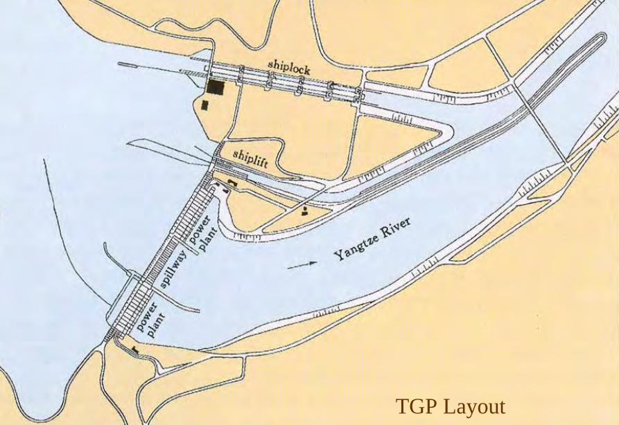
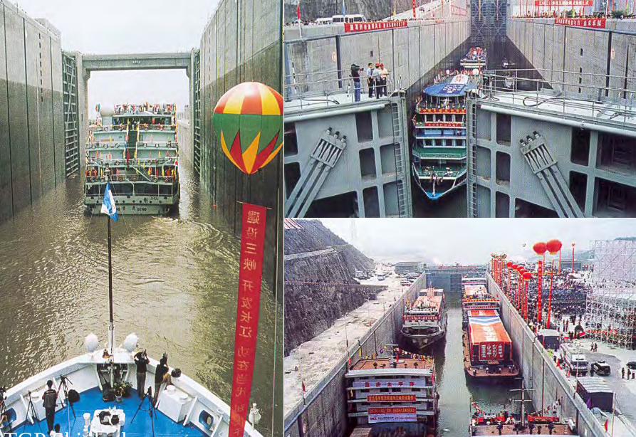
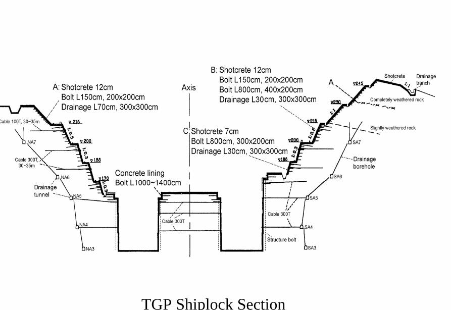
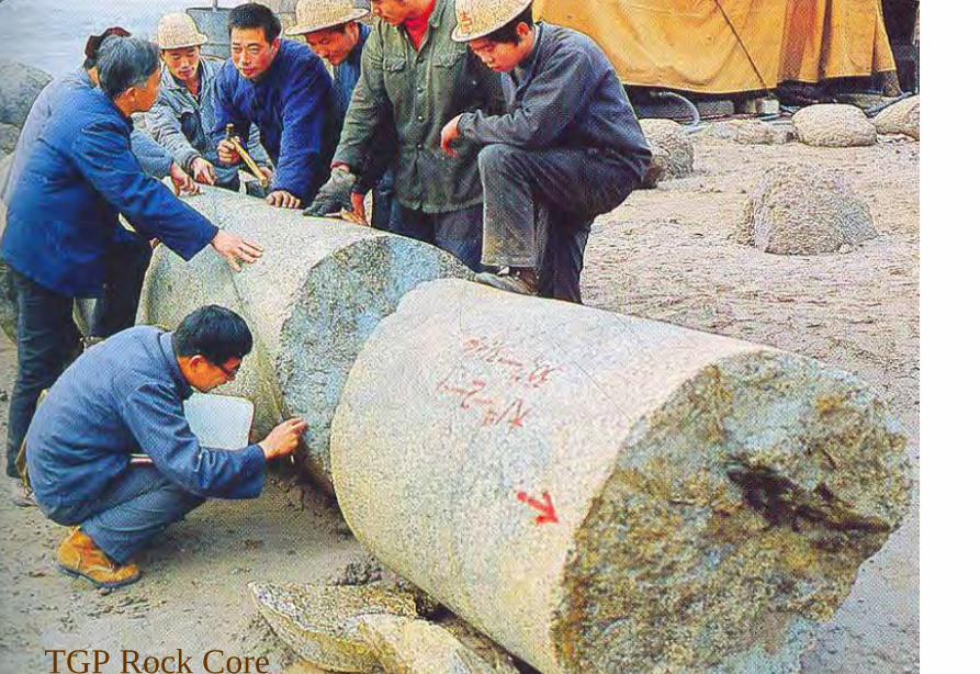
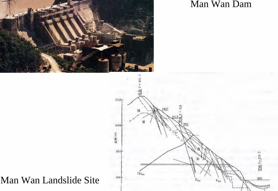
Da Lake
Xiao Lake
Yinping dam
Rockfallsource
Da Lake
四川大渡河滑坡壩(1933年大地震)
MUDFLOW OF THE LONGYANGXIA POWER STATION
Time of occurrenceAugust 4 of 1997 at 2355
Cause of the incidentA 2-hour constant rainfall with a total precipitation of 55 mm
Source of the mudflow material Natural deposit and construction waste in the Beidagou Gully
龙羊峡水电站128万千瓦
Geotechnical Issues (E) Tunnels and Excavations in Rock
- Fracture-induced instability (rock mass
classification and tunnel support design) - Stress-induced instability - Time-dependent deformation (eg Niagara vs
Three Gorges shiplocks)
Hoover Dam
Hoover Dam
廣州抽水蓄能電站
Two Types of Instability Underground
bull Stress ndash controlledbull Fracture - controlled
Rock Mass Classifications
bull Rock Quality Designation (RQD)
bull Rock Mass Rating System (RMR)
bull Rock Tunnelling Quality Index (Q)
Class Qualitative description BQ Value
I Hard rock intact gt 550
II Hard rock relatively intactRelatively hard rock intact
550 ~ 451
III Hard rock relatively fracturedRelatively hard or interlayered of hard and weak rock relatively
intactRelatively weak rock intact
450 ~ 351
IV Hard rock fracturedRelatively hard rock fractured-relatively fracturedRelatively weak rock or interlayered of weak and hard rock with dominant
weak rock relatively intact or relatively fracturedWeak rock intact or relatively intact
350 ~ 251
V Relatively weak rock fracturedWeak rock fractured-relatively fracturedExtremely weak rock extremely fractured
lt 250
National Standard for Engineering Classification of Rock Masses (GB 50218-94)
Table 1 Basic quality (BQ) of rock mass
BQ = 90 + 3 Rc + 250 Kv
where Rc = uniaxial compressive strength (MPa)Kv = intactness index of rock mass
Table 2 Classification based on uniaxial compressive strength Rc
Rc (MPa) gt 60 60 ~ 30 30 ~ 15 15 ~ 5 lt 5
Description Hard rock Relatively hard rock
Relatively weak rock
Weak rock Extremely weak rock
Table 4 Intactness Factor Kv as a function of Joint Index Jv
Jv (number of joints
m3)
lt 3 3 ~ 10 10 ~ 20 20 ~ 35 gt 35
Kv gt 075 075 ~ 055 055 ~ 035 035 ~ 015 lt 015
Kv =
Vpm= in-situ velocity of longitudinal elastic wave (kms)
Vpr = velocity of longitudinal elastic wave in intact rock (kms)
2
pt
pm
VV
⎟⎟⎠
⎞⎜⎜⎝
⎛
For engineering classification use [BQ] amended for groundwater joint orientation and in-situ stress conditions
[BQ] = BQ ndash 100 (K1 + K2 + K3)
where BQ = basic quality
K1 = correction factor for groundwater
K2 = correction factor for orientation of planes of weakness
K3 = correction factor for in-situ stress conditions
Table 5 K1 values - Correction factor for groundwater conditions
gt450 450 ~ 351 350 ~251 lt250
Wet or drops 0 01 02 ~ 03 04 ~ 06
Shower or flowP lt 01 MPa
Q lt 10 L min m
01 02 ~ 03 04 ~ 06 07 ~ 09
Shower or flowP lt01 MPa
Q lt 10 L min m
02 10
BQK1
Groundwaterinflow
Table 6 K2 values - Correction factor for orientation of planes of weakness
Relation of structure plane to tunnel axis
α lt 30 o= 30 o ~ 75 o
α gt 30 oβ gt 75 o
Other combinations
K2 04 ~ 06 0 ~ 02 02 ~ 04
α - angle between strike of structure plane and tunnel axisβ - dipping angle of structure plane
Table 7 K3 values - Correction factor for in-situ stress conditions
gt 550 550 ~ 351 450 ~ 351 350 ~251 lt 250
Extremely high stress
10 10 10 ~ 15 10 ~ 15 10
High stress 05 05 05 05 ~ 10 05 ~ 10
BQK3
Initialstress state
Technical Specifications for Water Resources and Hydropower ProjectsRock Mass Rating for Tunnelling Projects
Rock class
Rock stability Host rock
rating
StrengthStress S Support type
I Stable long termstability generally no unstable block
100 ~ 85 gt 4 No support or locally bolting or thin shotcreting in case of large span systematic shotcrete bolt and meshII Basically stable no
plasticity deformation85 ~ 65 gt 4
if S lt 4go to III
III Poor stability locally plasticity deformation or collapse
65 ~ 45 gt 2if S lt 2go to IV
Systematic shotcrete bolt and mesh if span = 20 ~ 25 m concrete lining is needed
IV Unstable short self-standing time large scale collapse
45 ~ 25 gt 2if S lt 2go to V
Systematic shotcrete bolt and mesh and concrete lining
V Extremely unstable severe collapse
lt 25 No limits
Host rock rating (HRR) = A + B + C + D + E(somewhat similar to Bieniawskirsquos RMR)
Rating on rock strength (A)
Type of rock materialHard rock Weak rock
Hard rock Moderately hard rock
Relatively weak rock
Weak rock
Uniaxial strength of saturated rock (MPa)
100 ~ 60 60 ~ 30 30 ~ 15 15 ~ 5
Rating (A)Hard rock 30 ~ 20 20 ~ 10
Weak rock 10 ~ 5 5 ~ 0
For uniaxial strength σc gt 100 MPa rock mass rating is 30
Rating on rock intactness (B)
Intactness Intact Relatively intact
Poor intactness
Relatively fractured
Fractured
Intactness factor Kv 10 ~ 075 075 ~ 055 055 ~ 035 035 ~ 015 lt 015
Hard rock 40 ~ 30 30 ~ 22 22 ~ 14 14 ~ 6 lt 6
Weak rock 25 ~ 19 19 ~ 14 14 ~ 9 9 ~ 4 lt 4
Rating (B)
Rating on state of structure planes (C)
Aperture (mm) Filling Roughness evenness Hard rock Relatively weak rock Weak rock
Closed lt 05Undulating rough 27 27 18
Planar smooth 21 21 14
Slight open 05 ~ 50
No filling Undulating rough 24 24 17Undulating smooth or
planar rough21 21 14
Planar smooth 15 15 8
Slacks
Undulating rough 21 21 14
Undulating smooth or planar rough
17 17 11
Planar smooth 12 12 8
Mud
Undulating rough 15 15 10
Undulating smooth or planar rough
12 12 8
Open gt 50
Planar smooth 9 9 6
Slacks 12 12 8Mud 6 6 4
For a length of structure plane which is less than 3 m in hard rock and relatively weak rock rating would increase by 3 for weak rock rating would increase by 2 For length gt 10 m decrease rating by 3 and 2 respectively for hard rock and relatively weak rock If aperture gt 10 m without filling rating is 0
Rating on groundwater condition (D)
Basic rating(A + B + C)
State Wet Drops Linear Flow Flow
Quantity of flow
(Lminm)
lt 25or
lt 10
25-125or
10-100
gt 125or
gt 100
Water head(m)
100-85
Rating on Groundwater Conditions
(D)
0 0 -2 ~ -6
85-65 0 ~ -2 0 ~ -2 -6 ~ -10
65-45 -2 ~ -6 -2 ~ -6 -10 ~ -14
45 ~ 25 -6 ~ -10 -10 ~ -14 -14 ~ -18
lt 25 -10 ~ -14 -14 ~ -18 -18 ~ -20
Rating on orientation of structure planes (E)
Angle betweenstrike of
structure planeand tunnel axis
( o )
90o ~ 60o 60o ~ 30o lt 30o
Dipping angle( o )
gt70 75~45 45~20 lt20 gt70 75~45 45~20 45~20
Crown -2
Wall -5
-5
-2
-12-10-10
0 -2 -5
-5
-10
lt20 gt70 70~45 lt20
0 -2 -12
0
-12-10
-12 0
-5
-2 -5 -10
Rating (E)
Factor Basis for Rating Rating
Saturated Compressive Strength (MPa) gt100 100-60 60-30 30-15 15-5
Rating for A gt30 30-20 20-10 10-5 5-0
Intactness Coefficient 10-075 075-055 055-035 035-015 lt015
σc gt 30 MPa 40-30 30-22 22-14 14-5 lt6
σc lt 30 MPa
Degree of openness
Infillings
Polishness of surface
σc gt 60 MPa
σc 60 - 30 MPa 27-21 24-15 21-12 15-9 12-6
18-14 17-8 14-8 10-6 8-4
gt10m
-3
-2
100-85
σc lt 30 MPa
70o- 45o 45o- 20o lt20o
-5 -10
0-2
-2
-5
σc gt 60 MPa
σc lt 60 MPa
Seeping dripping 0
Linear flow 0 rarr -2
-2 rarr -6
90o - 60o
gt70o
Roof 0
Sidewall -2
Gush of water
25-19 19-14 14-9 9-4 lt4
Closed lt05mm
Slightly open 05 ndash 50 mm Open gt 5 mm
Nil Rock fragments
Clay Fragmented Clay
Flat polished to curved rough
27-21 24-15 21-12 15-9 12-6
Length of structural surface lt3 m 3-10 m
+3 0
+2 0
A + B + C1 + C2 Rating 85-65 64-45 45-25 lt25
0 rarr -2 -2 rarr -6 -6 rarr -10 -10 rarr -14
-2 rarr -6 -6 rarr -10 -10 rarr -14 -14 rarr -18
-6 rarr -10 -10 rarr -14 -14 rarr -18 -18 rarr -20
Angle between tunnel alignment and structural orientation (strike)
60o - 30o lt 30o
Dip of structural orientation gt 70o 70o - 4 5o 45o - 20o lt 20o gt 70o 70o - 45o 45o - 20o lt 20o
2 -5 -10 -12 -5 -10 -12 -12
-5 -10 -2 0 -10 -12 -5 0
Rating for E
E
Rating for D
D
Rating for C2
C2
Rating for C1
Structural surface condition
C1
Rating for B
B
A
Host Rock Rating (HRR)
Recommended rock parameters
Class Gravity density γ(kNm3)
Friction angle ϕ (o)
Cohesion C(MPa)
Deformation module E(MPa)
Poisson ratio ν
I gt 60 gt 21 gt 33 lt 02
II 60 ~ 50 21 ~ 15 33 ~ 20 02 ~ 025
III 265 ~ 245 50 ~ 39 15 ~ 07 20 ~ 6 025 ~ 03
IV 245 ~ 225 39 ~ 27 07 ~ 02 6 ~ 13 03 ~ 035
V lt 225 lt 27 lt 02 lt 13 gt 035
gt 265
Recommended rock strength parameters
ClassConcrete-rock contact Rock mass Deformation
modulus
fprime cprime (MPa) fprime cprime (MPa) E0 X 104 (MPa)
I 15 ~ 13 15 ~ 13 16 ~ 14 25 ~ 20 gt 20
II 13 ~ 11 13 ~ 11 14 ~ 12 20 ~ 15 20 ~ 10
III 11 ~ 09 11 ~ 07 12 ~ 08 15 ~ 07 10 ~ 05
IV 09 ~ 07 07 ~ 03 08 ~ 055 07 ~ 03 05 ~ 02
V 07 ~ 04 03 ~ 005 055 ~ 040 03 ~ 005 02 ~ 002
fprime cprime - Shear strength
Design Applications of HRR
Rock PropertiesRock Type
Rock Mass Stability Host Rock
Rating (HRR)
Strength vs Stress Ratio (S) f C (MPa) E(x 104MPa)
Support Requirements
I Stable with long-term stability no unstable blocks in general
100 - 85 16 - 14 25 - 20 gt 20 Unsupported or localized boltsshotcrete or thin shotcrete add wire mesh for tunnels with large span
II Essentially stable with overall stability no plastic deformation localized rockfall
85 - 65 Downgrade to III for S lt 4
14 - 12 20 - 15 20 - 10
III Poor stability localized plastic deformation cave-in if unsupported temporarily stable in intact relatively soft rock
65 - 45 Downgrade to IV for S lt 2
12 - 08 15 - 07 10 - 05 Bolts and shotcrete with wire mesh concrete lining for tunnel span of 20 -25 m
IV Unstable very short standup time relatively large deformationfailure may occur
45 - 25 Downgrade to V for S lt 1
08 - 055 07 - 03 05 - 02 Bolts and shotcrete with re-bar mesh and concrete lining
V Very unstable could not stand up severe deformationfailure
lt 25 055 - 040 03 - 005 02 - 002
SUPPORT PARAMETERS(National Standard for Design of Bolt-shotcrete Support)
Span (m)Rock Class
B lt 5 m 5 lt B lt 10 10 lt B lt 20 15 lt B lt 20 20 lt B lt 25 m
I No support Shotcrete50 mm
(1) Shotcrete 80-100 mm(2) Shotcrete 50 mmbolt 20-25 m
Shotcrete Shotcrete 120-150 mmwith mesh bolt 30-40 m
II Shotcrete50 mm
(1) Shotcrete 80-100 mm(2) Shotcrete 50 mmbolt 15-2m
(1) Shotcrete 120-150 mm mesh if necessary(2) Shotcrete 80-120 mmbolt 2-3 m mesh if necessary
Shotcrete 120-150 mmmesh bolt 25-30 m
Shotcrete 150-200 mmmesh bolt 3-4 m
III (1) Shotcrete 80-100 mm(2) Shotcrete 50 mmbolt 15-2 m
(1) Shotcrete 120-150 mm mesh if necessary(2) Shotcrete 80-120 mmbolt 2-3 m mesh if necessary
Shotcrete 100-150 mmmesh bolt 20-30 m
Shotcrete 150-200 mmmesh bolt 3-4 m
IV Shotcrete 80-100 mmbolt 15-20 m
Shotcrete 100-200 mmmesh bolt 20-25 m bottom arch if necessary
Shotcrete 150-200 mmmesh bolt 25-30 m bottom arch if necessary
V Shotcrete 120-150 mmmesh bolt 15-20 m bottom arch if necessary
Shotcrete 150-200 mmmesh bolt 20-30 m bottom frame if necessary
GB-J86-85 (Revised)
Comparison of Rock Mass Classification Systems
System Range of Classes
Main Factors
Q 001-1000
9 RQD Jn (joint set number) Jr (joint roughness number) Ja (joint alteration number) Stress reduction factor SRF
RMR 0-100 5 Rock strength RQD Spacing conditions and orientation of joints Groundwater
HRR 0-100 5 Rock strength Intactness Conditions and Orientation of Weakness Planes Groundwater Initial Stresses
BQ lt 250-gt 500
5 Rock strength Intactness Groundwater Orientation of Weakness Planes Initial Stresses
Important Factors that are common among the various systems
1 Rock strength
2 Intactness
3 Condition of planes of weakness
4 Groundwater
5 Orientation of discontinuities
6 Initial stresses
Support systems for underground excavations in ChinaRock Class Span (m) Shotcrete Steel Mesh Bolt Concrete Lining
Total Number
of Projects
Thickness (cm)
Diameters(mm)
Spacing (m)
Diameter (mm)
Length (m)
Spacing (m)
Thickness(cm)
Number of Works
I 5-10 3-15 no no 18-22 12-30 Random no 9
10-15 3-20 6-12 025-15 18-22 15-35 10-15 no 9
15-20 10-20 no no 20-22 10-30 10-15 no 3
II 5-10 5-15 6-10 02-13 16-20 12-21 10-12 no 2 10
10-15 4-20 6-18 02-13 18-22 15-35 08-15 30-50 13
15-20 8-16 8-12 02-13 16-32 20-40 12-15 no 10
III 5-10 5-20 6-10 02-10 18-22 16-30 10-15 wall 1 12
10-15 5-20 5-12 02-10 16-24 15-35 10-15 11
15-20 10-16 6-12 02-08 16-30 20-40 08-12 8
IV 5-10 15-20 6-14 02-025 18-22 18-40 075-125 40 4 10
10-15 5-20 6-12 02-03 16-22 25-40 08-125 50 2 5
15-20 20 10-19 025 22 20 12 1
V 5-10 10-15 8-14 02-025 16-22 15-36 08-12 40 2
4
7
10-15 18-20 6-12 02-03 20-22 25-35 08-10 60 4
Three Gorges ProjectAmended [BQ] Values for Granite
Maximum [BQ]max = 630
Minimum [BQ]min = 500
Average [BQ]mean = 565
Class I- to II+
Guangzhou Pumped Storage Project
bull Location north of Guangzhou Guangdong Province
bull Underground Powerhouse
1465 m x 22 m x 445 m (L x W x H)
at 330 - 400 m depth completed in 1993
bull Host Rock Biotite granite
bull Support System Bolts (at 2 x 15 m spacing)+ 15 cm shotcrete in both crown and
sidewalls
Xiaolangdi Project
bull Location on Yellow River Henan Provincebull Underground Powerhouse
2515 m x 262 m x 614m (L x W x H)At 70 ndash 100 m depth completed in 1999
bull Host Rock Sandstone with argillaceous bedsbull Support System Bolts (at 15 spacing) with wiremesh
and shotcret (20 cm) in crownBolts (at 15 spacing) in sidewallsAnchors locally where required
Xiaolangdi Project on Yellow RiverProposed support parameters in design stage
Support DesignCavern Type Location Rock Type
Rock Grade Tensile Bolt Re Shotcrete
Top T14 III Φ 25 15 X 15 m (mortar bolt)
L = 53 m (alternatively)Φ 6 20 X 20 cmδ = 10 cm (C20)
Tailrace Cavern
Top T14 III Φ 28 15 X 15 m
L = 84 m (alternatively)Φ 8 20 X 20 cmδ = 20 cm (C20)
Sidewall T14
T13-2
III Φ 25 15 X 15 mL = 128 m (alternatively)
Φ 8 20 X 20 cmδ = 15 cm (C20)
Top T14 II- Φ 25 15 X 15 m
L = 73 m (alternatively)Φ 6 20 X 20 cmδ = 15 cm (C20)
Sidewall T14 II- Φ 25 15 X 15 m
L = 53 m (alternatively)Φ 6 20 X 20 cmδ = 10 cm (C20)
Sidewall T14 III Φ 25 15 X 15 m (mortar bolt)
L = 4 mΦ 6 25 X 25 cmδ = 10 cm (C20)
Transformer Cavern
Main Power-house
T14 thick to massive siliceous fine-grained sandstone
T13-2 thick to massive argillaceous and calcareous silty fine-grained sandstone
Xiaolangdi Project on Yellow RiverActual support used at construction stage
Support DesignCavern Type Location Rock Type
Rock Grade Tensile Bolt Re Shotcrete
Support Pres
(MPa)0112
0056
0104
0104
056
0044
Top T14 III Φ 32 3 X 3 m L = 5 m P = 150 KN
Φ 32 3 X 3 m L = 3 m P = 150 KNΦ 6 25 X 25 cmδ = 15 cm (C20)
Tailrace Cavern
Top T14 III Φ 32 3 X 3 m L = 8 m P = 150 KN
Φ 32 3 X 3 m L = 6 m P = 150 KNCable L = 25 m 45 X 6 m P = 1500 KN
Φ 8 20 X 20 cmδ = 20 cm (C20)
Sidewall T14
T13-2
III Φ 32 3 X 3 m L = 10 m P = 150 KNΦ 32 3 X 3 m L = 6 m P = 150 KNTwo rows of pre-stressed bolt added for argillized interlayers 500 KN L = 15 m
Φ 8 20 X 20 cmδ = 20 cm (C20)
Top T14 II- Φ 32 24 X 24 m L = 8 m P = 150 KN
Φ 32 24 X 24 m L = 4 m P = 150 KNΦ 6 20 X 20 cmδ = 20 cm (C20)
Sidewall T14 II- Φ 32 24 X 24 m L = 6 m P = 150 KN
Φ 32 24 X 24 m L = 4 m P = 150 KNΦ 6 25 X 25 cmδ = 15 cm (C20)
Sidewall T14 III Φ 32 15 X 15 m
L = 4 m P = 100 KNΦ 6 25 X 25 cmδ = 10 cm (C20)
Transformer Cavern
Main Power-house
Er Tan Dam
Er Tan Dam
Er Tan Dam Layout
Er Tan Dam Layout
Er Tan Under Construction
Er Tan Under Construction
Er Tan Underground Power House
Er Tan Underground Power House
Er Tan Diversion Tunnel
Er Tan Diversion Tunnel
Er Tan Rock Discing
Er Tan Rock Discing
Er Tan Geostress
Er Tan Geostress(kgcm2)
Strain Energy Approach to Modelling Rock Squeeze Problems
For a virtual displacement δ e
Work Done = Force x Displacement = Feδ e = (δ e)TFe
where Fe = corresponding nodal force Strain energy recovered from unit volume of rock = Stress x Strain = σ ε = ε Tσ = ([B] δ e)T ([D]ε ) = (δ e)T[B][D] ε Work Done = Strain Energy Released (δ e)TFe = (δ e)T int vol [B]T[D] ε dv
or Fe = int vol [B]T[D] ε dv
Some Features of Chinese Hydro Projects
bull Same design framework as in the Westbull Very detailed site investigationsbull Including numerous aditsbull Sometimes leads to significant cost savingsbull (eg Ertan dam allowed to be founded on Class III
rock instead of Class II as called for by Design Standard
bull Strong emphasis on geology and rock mass structure studies
bull Very detailed analysis including numerical modelling AI etc
青海龍羊峽
青海 黃河 李家峽 拱壩壩址
青海 李家峽
探洞
滑面
滑面
李家峽水庫 老滑坡體
剖面
電力需求增長
水電資源
Schematic Map of Hydropower Stations of 1GW and above in Operation or Under Construction
Jin Sha River Hydro Power
南水北調三線
Method of Generation Pros Cons
Capital Construction Cost
(Ratio) Fuel Cost
Fossil
bull Short construction period (2-3 years)
bull Easy to start up
bull Air pollution bull Ashsludge
disposal 1 Relatively high
Hydraulic
bull Longer construction period (gt 5 years)
bull Resettlement of affected population
bull Preservation of cultural amp historic relics
2
Nuclear
bull Relatively long construction period (ge 10 years)
bull Nuclear safety concern
bull Nuclear waste disposal needs
5 Relatively low
Other generation methods solar wind biomass etc
The Joy of being a Hydro Project Engineer
bull Free helicopter jet rides(safe most of the time)
bull Exotic places with breathtaking scenerysceneryand colorful folklore(no tourists around no phone calls etc)
攔路酒(四川 涼山)
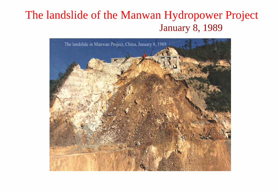
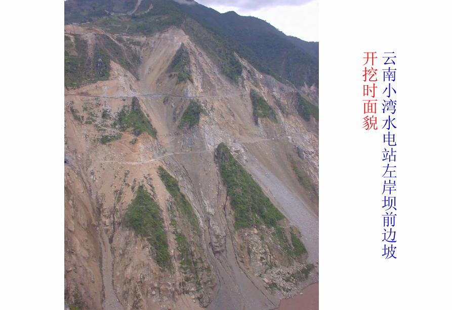
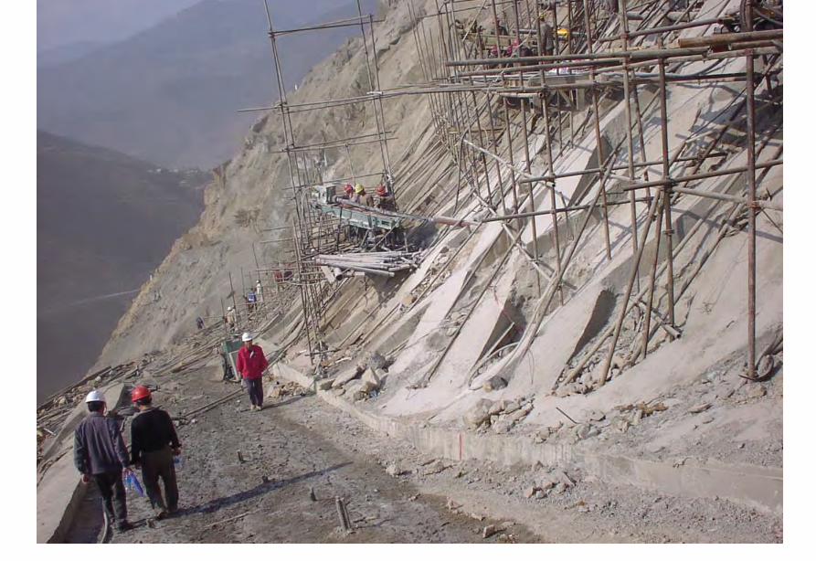
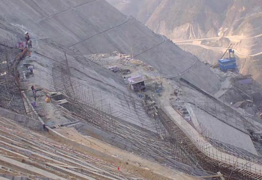
Hoover Dam
Hoover Dam
廣州抽水蓄能電站
Two Types of Instability Underground
bull Stress ndash controlledbull Fracture - controlled
Rock Mass Classifications
bull Rock Quality Designation (RQD)
bull Rock Mass Rating System (RMR)
bull Rock Tunnelling Quality Index (Q)
Class Qualitative description BQ Value
I Hard rock intact gt 550
II Hard rock relatively intactRelatively hard rock intact
550 ~ 451
III Hard rock relatively fracturedRelatively hard or interlayered of hard and weak rock relatively
intactRelatively weak rock intact
450 ~ 351
IV Hard rock fracturedRelatively hard rock fractured-relatively fracturedRelatively weak rock or interlayered of weak and hard rock with dominant
weak rock relatively intact or relatively fracturedWeak rock intact or relatively intact
350 ~ 251
V Relatively weak rock fracturedWeak rock fractured-relatively fracturedExtremely weak rock extremely fractured
lt 250
National Standard for Engineering Classification of Rock Masses (GB 50218-94)
Table 1 Basic quality (BQ) of rock mass
BQ = 90 + 3 Rc + 250 Kv
where Rc = uniaxial compressive strength (MPa)Kv = intactness index of rock mass
Table 2 Classification based on uniaxial compressive strength Rc
Rc (MPa) gt 60 60 ~ 30 30 ~ 15 15 ~ 5 lt 5
Description Hard rock Relatively hard rock
Relatively weak rock
Weak rock Extremely weak rock
Table 4 Intactness Factor Kv as a function of Joint Index Jv
Jv (number of joints
m3)
lt 3 3 ~ 10 10 ~ 20 20 ~ 35 gt 35
Kv gt 075 075 ~ 055 055 ~ 035 035 ~ 015 lt 015
Kv =
Vpm= in-situ velocity of longitudinal elastic wave (kms)
Vpr = velocity of longitudinal elastic wave in intact rock (kms)
2
pt
pm
VV
⎟⎟⎠
⎞⎜⎜⎝
⎛
For engineering classification use [BQ] amended for groundwater joint orientation and in-situ stress conditions
[BQ] = BQ ndash 100 (K1 + K2 + K3)
where BQ = basic quality
K1 = correction factor for groundwater
K2 = correction factor for orientation of planes of weakness
K3 = correction factor for in-situ stress conditions
Table 5 K1 values - Correction factor for groundwater conditions
gt450 450 ~ 351 350 ~251 lt250
Wet or drops 0 01 02 ~ 03 04 ~ 06
Shower or flowP lt 01 MPa
Q lt 10 L min m
01 02 ~ 03 04 ~ 06 07 ~ 09
Shower or flowP lt01 MPa
Q lt 10 L min m
02 10
BQK1
Groundwaterinflow
Table 6 K2 values - Correction factor for orientation of planes of weakness
Relation of structure plane to tunnel axis
α lt 30 o= 30 o ~ 75 o
α gt 30 oβ gt 75 o
Other combinations
K2 04 ~ 06 0 ~ 02 02 ~ 04
α - angle between strike of structure plane and tunnel axisβ - dipping angle of structure plane
Table 7 K3 values - Correction factor for in-situ stress conditions
gt 550 550 ~ 351 450 ~ 351 350 ~251 lt 250
Extremely high stress
10 10 10 ~ 15 10 ~ 15 10
High stress 05 05 05 05 ~ 10 05 ~ 10
BQK3
Initialstress state
Technical Specifications for Water Resources and Hydropower ProjectsRock Mass Rating for Tunnelling Projects
Rock class
Rock stability Host rock
rating
StrengthStress S Support type
I Stable long termstability generally no unstable block
100 ~ 85 gt 4 No support or locally bolting or thin shotcreting in case of large span systematic shotcrete bolt and meshII Basically stable no
plasticity deformation85 ~ 65 gt 4
if S lt 4go to III
III Poor stability locally plasticity deformation or collapse
65 ~ 45 gt 2if S lt 2go to IV
Systematic shotcrete bolt and mesh if span = 20 ~ 25 m concrete lining is needed
IV Unstable short self-standing time large scale collapse
45 ~ 25 gt 2if S lt 2go to V
Systematic shotcrete bolt and mesh and concrete lining
V Extremely unstable severe collapse
lt 25 No limits
Host rock rating (HRR) = A + B + C + D + E(somewhat similar to Bieniawskirsquos RMR)
Rating on rock strength (A)
Type of rock materialHard rock Weak rock
Hard rock Moderately hard rock
Relatively weak rock
Weak rock
Uniaxial strength of saturated rock (MPa)
100 ~ 60 60 ~ 30 30 ~ 15 15 ~ 5
Rating (A)Hard rock 30 ~ 20 20 ~ 10
Weak rock 10 ~ 5 5 ~ 0
For uniaxial strength σc gt 100 MPa rock mass rating is 30
Rating on rock intactness (B)
Intactness Intact Relatively intact
Poor intactness
Relatively fractured
Fractured
Intactness factor Kv 10 ~ 075 075 ~ 055 055 ~ 035 035 ~ 015 lt 015
Hard rock 40 ~ 30 30 ~ 22 22 ~ 14 14 ~ 6 lt 6
Weak rock 25 ~ 19 19 ~ 14 14 ~ 9 9 ~ 4 lt 4
Rating (B)
Rating on state of structure planes (C)
Aperture (mm) Filling Roughness evenness Hard rock Relatively weak rock Weak rock
Closed lt 05Undulating rough 27 27 18
Planar smooth 21 21 14
Slight open 05 ~ 50
No filling Undulating rough 24 24 17Undulating smooth or
planar rough21 21 14
Planar smooth 15 15 8
Slacks
Undulating rough 21 21 14
Undulating smooth or planar rough
17 17 11
Planar smooth 12 12 8
Mud
Undulating rough 15 15 10
Undulating smooth or planar rough
12 12 8
Open gt 50
Planar smooth 9 9 6
Slacks 12 12 8Mud 6 6 4
For a length of structure plane which is less than 3 m in hard rock and relatively weak rock rating would increase by 3 for weak rock rating would increase by 2 For length gt 10 m decrease rating by 3 and 2 respectively for hard rock and relatively weak rock If aperture gt 10 m without filling rating is 0
Rating on groundwater condition (D)
Basic rating(A + B + C)
State Wet Drops Linear Flow Flow
Quantity of flow
(Lminm)
lt 25or
lt 10
25-125or
10-100
gt 125or
gt 100
Water head(m)
100-85
Rating on Groundwater Conditions
(D)
0 0 -2 ~ -6
85-65 0 ~ -2 0 ~ -2 -6 ~ -10
65-45 -2 ~ -6 -2 ~ -6 -10 ~ -14
45 ~ 25 -6 ~ -10 -10 ~ -14 -14 ~ -18
lt 25 -10 ~ -14 -14 ~ -18 -18 ~ -20
Rating on orientation of structure planes (E)
Angle betweenstrike of
structure planeand tunnel axis
( o )
90o ~ 60o 60o ~ 30o lt 30o
Dipping angle( o )
gt70 75~45 45~20 lt20 gt70 75~45 45~20 45~20
Crown -2
Wall -5
-5
-2
-12-10-10
0 -2 -5
-5
-10
lt20 gt70 70~45 lt20
0 -2 -12
0
-12-10
-12 0
-5
-2 -5 -10
Rating (E)
Factor Basis for Rating Rating
Saturated Compressive Strength (MPa) gt100 100-60 60-30 30-15 15-5
Rating for A gt30 30-20 20-10 10-5 5-0
Intactness Coefficient 10-075 075-055 055-035 035-015 lt015
σc gt 30 MPa 40-30 30-22 22-14 14-5 lt6
σc lt 30 MPa
Degree of openness
Infillings
Polishness of surface
σc gt 60 MPa
σc 60 - 30 MPa 27-21 24-15 21-12 15-9 12-6
18-14 17-8 14-8 10-6 8-4
gt10m
-3
-2
100-85
σc lt 30 MPa
70o- 45o 45o- 20o lt20o
-5 -10
0-2
-2
-5
σc gt 60 MPa
σc lt 60 MPa
Seeping dripping 0
Linear flow 0 rarr -2
-2 rarr -6
90o - 60o
gt70o
Roof 0
Sidewall -2
Gush of water
25-19 19-14 14-9 9-4 lt4
Closed lt05mm
Slightly open 05 ndash 50 mm Open gt 5 mm
Nil Rock fragments
Clay Fragmented Clay
Flat polished to curved rough
27-21 24-15 21-12 15-9 12-6
Length of structural surface lt3 m 3-10 m
+3 0
+2 0
A + B + C1 + C2 Rating 85-65 64-45 45-25 lt25
0 rarr -2 -2 rarr -6 -6 rarr -10 -10 rarr -14
-2 rarr -6 -6 rarr -10 -10 rarr -14 -14 rarr -18
-6 rarr -10 -10 rarr -14 -14 rarr -18 -18 rarr -20
Angle between tunnel alignment and structural orientation (strike)
60o - 30o lt 30o
Dip of structural orientation gt 70o 70o - 4 5o 45o - 20o lt 20o gt 70o 70o - 45o 45o - 20o lt 20o
2 -5 -10 -12 -5 -10 -12 -12
-5 -10 -2 0 -10 -12 -5 0
Rating for E
E
Rating for D
D
Rating for C2
C2
Rating for C1
Structural surface condition
C1
Rating for B
B
A
Host Rock Rating (HRR)
Recommended rock parameters
Class Gravity density γ(kNm3)
Friction angle ϕ (o)
Cohesion C(MPa)
Deformation module E(MPa)
Poisson ratio ν
I gt 60 gt 21 gt 33 lt 02
II 60 ~ 50 21 ~ 15 33 ~ 20 02 ~ 025
III 265 ~ 245 50 ~ 39 15 ~ 07 20 ~ 6 025 ~ 03
IV 245 ~ 225 39 ~ 27 07 ~ 02 6 ~ 13 03 ~ 035
V lt 225 lt 27 lt 02 lt 13 gt 035
gt 265
Recommended rock strength parameters
ClassConcrete-rock contact Rock mass Deformation
modulus
fprime cprime (MPa) fprime cprime (MPa) E0 X 104 (MPa)
I 15 ~ 13 15 ~ 13 16 ~ 14 25 ~ 20 gt 20
II 13 ~ 11 13 ~ 11 14 ~ 12 20 ~ 15 20 ~ 10
III 11 ~ 09 11 ~ 07 12 ~ 08 15 ~ 07 10 ~ 05
IV 09 ~ 07 07 ~ 03 08 ~ 055 07 ~ 03 05 ~ 02
V 07 ~ 04 03 ~ 005 055 ~ 040 03 ~ 005 02 ~ 002
fprime cprime - Shear strength
Design Applications of HRR
Rock PropertiesRock Type
Rock Mass Stability Host Rock
Rating (HRR)
Strength vs Stress Ratio (S) f C (MPa) E(x 104MPa)
Support Requirements
I Stable with long-term stability no unstable blocks in general
100 - 85 16 - 14 25 - 20 gt 20 Unsupported or localized boltsshotcrete or thin shotcrete add wire mesh for tunnels with large span
II Essentially stable with overall stability no plastic deformation localized rockfall
85 - 65 Downgrade to III for S lt 4
14 - 12 20 - 15 20 - 10
III Poor stability localized plastic deformation cave-in if unsupported temporarily stable in intact relatively soft rock
65 - 45 Downgrade to IV for S lt 2
12 - 08 15 - 07 10 - 05 Bolts and shotcrete with wire mesh concrete lining for tunnel span of 20 -25 m
IV Unstable very short standup time relatively large deformationfailure may occur
45 - 25 Downgrade to V for S lt 1
08 - 055 07 - 03 05 - 02 Bolts and shotcrete with re-bar mesh and concrete lining
V Very unstable could not stand up severe deformationfailure
lt 25 055 - 040 03 - 005 02 - 002
SUPPORT PARAMETERS(National Standard for Design of Bolt-shotcrete Support)
Span (m)Rock Class
B lt 5 m 5 lt B lt 10 10 lt B lt 20 15 lt B lt 20 20 lt B lt 25 m
I No support Shotcrete50 mm
(1) Shotcrete 80-100 mm(2) Shotcrete 50 mmbolt 20-25 m
Shotcrete Shotcrete 120-150 mmwith mesh bolt 30-40 m
II Shotcrete50 mm
(1) Shotcrete 80-100 mm(2) Shotcrete 50 mmbolt 15-2m
(1) Shotcrete 120-150 mm mesh if necessary(2) Shotcrete 80-120 mmbolt 2-3 m mesh if necessary
Shotcrete 120-150 mmmesh bolt 25-30 m
Shotcrete 150-200 mmmesh bolt 3-4 m
III (1) Shotcrete 80-100 mm(2) Shotcrete 50 mmbolt 15-2 m
(1) Shotcrete 120-150 mm mesh if necessary(2) Shotcrete 80-120 mmbolt 2-3 m mesh if necessary
Shotcrete 100-150 mmmesh bolt 20-30 m
Shotcrete 150-200 mmmesh bolt 3-4 m
IV Shotcrete 80-100 mmbolt 15-20 m
Shotcrete 100-200 mmmesh bolt 20-25 m bottom arch if necessary
Shotcrete 150-200 mmmesh bolt 25-30 m bottom arch if necessary
V Shotcrete 120-150 mmmesh bolt 15-20 m bottom arch if necessary
Shotcrete 150-200 mmmesh bolt 20-30 m bottom frame if necessary
GB-J86-85 (Revised)
Comparison of Rock Mass Classification Systems
System Range of Classes
Main Factors
Q 001-1000
9 RQD Jn (joint set number) Jr (joint roughness number) Ja (joint alteration number) Stress reduction factor SRF
RMR 0-100 5 Rock strength RQD Spacing conditions and orientation of joints Groundwater
HRR 0-100 5 Rock strength Intactness Conditions and Orientation of Weakness Planes Groundwater Initial Stresses
BQ lt 250-gt 500
5 Rock strength Intactness Groundwater Orientation of Weakness Planes Initial Stresses
Important Factors that are common among the various systems
1 Rock strength
2 Intactness
3 Condition of planes of weakness
4 Groundwater
5 Orientation of discontinuities
6 Initial stresses
Support systems for underground excavations in ChinaRock Class Span (m) Shotcrete Steel Mesh Bolt Concrete Lining
Total Number
of Projects
Thickness (cm)
Diameters(mm)
Spacing (m)
Diameter (mm)
Length (m)
Spacing (m)
Thickness(cm)
Number of Works
I 5-10 3-15 no no 18-22 12-30 Random no 9
10-15 3-20 6-12 025-15 18-22 15-35 10-15 no 9
15-20 10-20 no no 20-22 10-30 10-15 no 3
II 5-10 5-15 6-10 02-13 16-20 12-21 10-12 no 2 10
10-15 4-20 6-18 02-13 18-22 15-35 08-15 30-50 13
15-20 8-16 8-12 02-13 16-32 20-40 12-15 no 10
III 5-10 5-20 6-10 02-10 18-22 16-30 10-15 wall 1 12
10-15 5-20 5-12 02-10 16-24 15-35 10-15 11
15-20 10-16 6-12 02-08 16-30 20-40 08-12 8
IV 5-10 15-20 6-14 02-025 18-22 18-40 075-125 40 4 10
10-15 5-20 6-12 02-03 16-22 25-40 08-125 50 2 5
15-20 20 10-19 025 22 20 12 1
V 5-10 10-15 8-14 02-025 16-22 15-36 08-12 40 2
4
7
10-15 18-20 6-12 02-03 20-22 25-35 08-10 60 4
Three Gorges ProjectAmended [BQ] Values for Granite
Maximum [BQ]max = 630
Minimum [BQ]min = 500
Average [BQ]mean = 565
Class I- to II+
Guangzhou Pumped Storage Project
bull Location north of Guangzhou Guangdong Province
bull Underground Powerhouse
1465 m x 22 m x 445 m (L x W x H)
at 330 - 400 m depth completed in 1993
bull Host Rock Biotite granite
bull Support System Bolts (at 2 x 15 m spacing)+ 15 cm shotcrete in both crown and
sidewalls
Xiaolangdi Project
bull Location on Yellow River Henan Provincebull Underground Powerhouse
2515 m x 262 m x 614m (L x W x H)At 70 ndash 100 m depth completed in 1999
bull Host Rock Sandstone with argillaceous bedsbull Support System Bolts (at 15 spacing) with wiremesh
and shotcret (20 cm) in crownBolts (at 15 spacing) in sidewallsAnchors locally where required
Xiaolangdi Project on Yellow RiverProposed support parameters in design stage
Support DesignCavern Type Location Rock Type
Rock Grade Tensile Bolt Re Shotcrete
Top T14 III Φ 25 15 X 15 m (mortar bolt)
L = 53 m (alternatively)Φ 6 20 X 20 cmδ = 10 cm (C20)
Tailrace Cavern
Top T14 III Φ 28 15 X 15 m
L = 84 m (alternatively)Φ 8 20 X 20 cmδ = 20 cm (C20)
Sidewall T14
T13-2
III Φ 25 15 X 15 mL = 128 m (alternatively)
Φ 8 20 X 20 cmδ = 15 cm (C20)
Top T14 II- Φ 25 15 X 15 m
L = 73 m (alternatively)Φ 6 20 X 20 cmδ = 15 cm (C20)
Sidewall T14 II- Φ 25 15 X 15 m
L = 53 m (alternatively)Φ 6 20 X 20 cmδ = 10 cm (C20)
Sidewall T14 III Φ 25 15 X 15 m (mortar bolt)
L = 4 mΦ 6 25 X 25 cmδ = 10 cm (C20)
Transformer Cavern
Main Power-house
T14 thick to massive siliceous fine-grained sandstone
T13-2 thick to massive argillaceous and calcareous silty fine-grained sandstone
Xiaolangdi Project on Yellow RiverActual support used at construction stage
Support DesignCavern Type Location Rock Type
Rock Grade Tensile Bolt Re Shotcrete
Support Pres
(MPa)0112
0056
0104
0104
056
0044
Top T14 III Φ 32 3 X 3 m L = 5 m P = 150 KN
Φ 32 3 X 3 m L = 3 m P = 150 KNΦ 6 25 X 25 cmδ = 15 cm (C20)
Tailrace Cavern
Top T14 III Φ 32 3 X 3 m L = 8 m P = 150 KN
Φ 32 3 X 3 m L = 6 m P = 150 KNCable L = 25 m 45 X 6 m P = 1500 KN
Φ 8 20 X 20 cmδ = 20 cm (C20)
Sidewall T14
T13-2
III Φ 32 3 X 3 m L = 10 m P = 150 KNΦ 32 3 X 3 m L = 6 m P = 150 KNTwo rows of pre-stressed bolt added for argillized interlayers 500 KN L = 15 m
Φ 8 20 X 20 cmδ = 20 cm (C20)
Top T14 II- Φ 32 24 X 24 m L = 8 m P = 150 KN
Φ 32 24 X 24 m L = 4 m P = 150 KNΦ 6 20 X 20 cmδ = 20 cm (C20)
Sidewall T14 II- Φ 32 24 X 24 m L = 6 m P = 150 KN
Φ 32 24 X 24 m L = 4 m P = 150 KNΦ 6 25 X 25 cmδ = 15 cm (C20)
Sidewall T14 III Φ 32 15 X 15 m
L = 4 m P = 100 KNΦ 6 25 X 25 cmδ = 10 cm (C20)
Transformer Cavern
Main Power-house
Er Tan Dam
Er Tan Dam
Er Tan Dam Layout
Er Tan Dam Layout
Er Tan Under Construction
Er Tan Under Construction
Er Tan Underground Power House
Er Tan Underground Power House
Er Tan Diversion Tunnel
Er Tan Diversion Tunnel
Er Tan Rock Discing
Er Tan Rock Discing
Er Tan Geostress
Er Tan Geostress(kgcm2)
Strain Energy Approach to Modelling Rock Squeeze Problems
For a virtual displacement δ e
Work Done = Force x Displacement = Feδ e = (δ e)TFe
where Fe = corresponding nodal force Strain energy recovered from unit volume of rock = Stress x Strain = σ ε = ε Tσ = ([B] δ e)T ([D]ε ) = (δ e)T[B][D] ε Work Done = Strain Energy Released (δ e)TFe = (δ e)T int vol [B]T[D] ε dv
or Fe = int vol [B]T[D] ε dv
Some Features of Chinese Hydro Projects
bull Same design framework as in the Westbull Very detailed site investigationsbull Including numerous aditsbull Sometimes leads to significant cost savingsbull (eg Ertan dam allowed to be founded on Class III
rock instead of Class II as called for by Design Standard
bull Strong emphasis on geology and rock mass structure studies
bull Very detailed analysis including numerical modelling AI etc
青海龍羊峽
青海 黃河 李家峽 拱壩壩址
青海 李家峽
探洞
滑面
滑面
李家峽水庫 老滑坡體
剖面
電力需求增長
水電資源
Schematic Map of Hydropower Stations of 1GW and above in Operation or Under Construction
Jin Sha River Hydro Power
南水北調三線
Method of Generation Pros Cons
Capital Construction Cost
(Ratio) Fuel Cost
Fossil
bull Short construction period (2-3 years)
bull Easy to start up
bull Air pollution bull Ashsludge
disposal 1 Relatively high
Hydraulic
bull Longer construction period (gt 5 years)
bull Resettlement of affected population
bull Preservation of cultural amp historic relics
2
Nuclear
bull Relatively long construction period (ge 10 years)
bull Nuclear safety concern
bull Nuclear waste disposal needs
5 Relatively low
Other generation methods solar wind biomass etc
The Joy of being a Hydro Project Engineer
bull Free helicopter jet rides(safe most of the time)
bull Exotic places with breathtaking scenerysceneryand colorful folklore(no tourists around no phone calls etc)
攔路酒(四川 涼山)
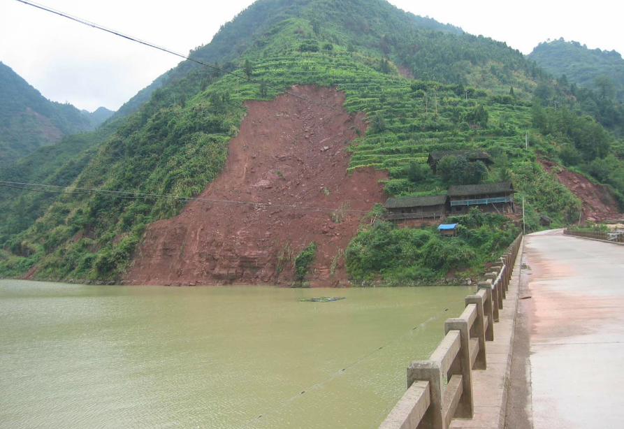
Hoover Dam
廣州抽水蓄能電站
Two Types of Instability Underground
bull Stress ndash controlledbull Fracture - controlled
Rock Mass Classifications
bull Rock Quality Designation (RQD)
bull Rock Mass Rating System (RMR)
bull Rock Tunnelling Quality Index (Q)
Class Qualitative description BQ Value
I Hard rock intact gt 550
II Hard rock relatively intactRelatively hard rock intact
550 ~ 451
III Hard rock relatively fracturedRelatively hard or interlayered of hard and weak rock relatively
intactRelatively weak rock intact
450 ~ 351
IV Hard rock fracturedRelatively hard rock fractured-relatively fracturedRelatively weak rock or interlayered of weak and hard rock with dominant
weak rock relatively intact or relatively fracturedWeak rock intact or relatively intact
350 ~ 251
V Relatively weak rock fracturedWeak rock fractured-relatively fracturedExtremely weak rock extremely fractured
lt 250
National Standard for Engineering Classification of Rock Masses (GB 50218-94)
Table 1 Basic quality (BQ) of rock mass
BQ = 90 + 3 Rc + 250 Kv
where Rc = uniaxial compressive strength (MPa)Kv = intactness index of rock mass
Table 2 Classification based on uniaxial compressive strength Rc
Rc (MPa) gt 60 60 ~ 30 30 ~ 15 15 ~ 5 lt 5
Description Hard rock Relatively hard rock
Relatively weak rock
Weak rock Extremely weak rock
Table 4 Intactness Factor Kv as a function of Joint Index Jv
Jv (number of joints
m3)
lt 3 3 ~ 10 10 ~ 20 20 ~ 35 gt 35
Kv gt 075 075 ~ 055 055 ~ 035 035 ~ 015 lt 015
Kv =
Vpm= in-situ velocity of longitudinal elastic wave (kms)
Vpr = velocity of longitudinal elastic wave in intact rock (kms)
2
pt
pm
VV
⎟⎟⎠
⎞⎜⎜⎝
⎛
For engineering classification use [BQ] amended for groundwater joint orientation and in-situ stress conditions
[BQ] = BQ ndash 100 (K1 + K2 + K3)
where BQ = basic quality
K1 = correction factor for groundwater
K2 = correction factor for orientation of planes of weakness
K3 = correction factor for in-situ stress conditions
Table 5 K1 values - Correction factor for groundwater conditions
gt450 450 ~ 351 350 ~251 lt250
Wet or drops 0 01 02 ~ 03 04 ~ 06
Shower or flowP lt 01 MPa
Q lt 10 L min m
01 02 ~ 03 04 ~ 06 07 ~ 09
Shower or flowP lt01 MPa
Q lt 10 L min m
02 10
BQK1
Groundwaterinflow
Table 6 K2 values - Correction factor for orientation of planes of weakness
Relation of structure plane to tunnel axis
α lt 30 o= 30 o ~ 75 o
α gt 30 oβ gt 75 o
Other combinations
K2 04 ~ 06 0 ~ 02 02 ~ 04
α - angle between strike of structure plane and tunnel axisβ - dipping angle of structure plane
Table 7 K3 values - Correction factor for in-situ stress conditions
gt 550 550 ~ 351 450 ~ 351 350 ~251 lt 250
Extremely high stress
10 10 10 ~ 15 10 ~ 15 10
High stress 05 05 05 05 ~ 10 05 ~ 10
BQK3
Initialstress state
Technical Specifications for Water Resources and Hydropower ProjectsRock Mass Rating for Tunnelling Projects
Rock class
Rock stability Host rock
rating
StrengthStress S Support type
I Stable long termstability generally no unstable block
100 ~ 85 gt 4 No support or locally bolting or thin shotcreting in case of large span systematic shotcrete bolt and meshII Basically stable no
plasticity deformation85 ~ 65 gt 4
if S lt 4go to III
III Poor stability locally plasticity deformation or collapse
65 ~ 45 gt 2if S lt 2go to IV
Systematic shotcrete bolt and mesh if span = 20 ~ 25 m concrete lining is needed
IV Unstable short self-standing time large scale collapse
45 ~ 25 gt 2if S lt 2go to V
Systematic shotcrete bolt and mesh and concrete lining
V Extremely unstable severe collapse
lt 25 No limits
Host rock rating (HRR) = A + B + C + D + E(somewhat similar to Bieniawskirsquos RMR)
Rating on rock strength (A)
Type of rock materialHard rock Weak rock
Hard rock Moderately hard rock
Relatively weak rock
Weak rock
Uniaxial strength of saturated rock (MPa)
100 ~ 60 60 ~ 30 30 ~ 15 15 ~ 5
Rating (A)Hard rock 30 ~ 20 20 ~ 10
Weak rock 10 ~ 5 5 ~ 0
For uniaxial strength σc gt 100 MPa rock mass rating is 30
Rating on rock intactness (B)
Intactness Intact Relatively intact
Poor intactness
Relatively fractured
Fractured
Intactness factor Kv 10 ~ 075 075 ~ 055 055 ~ 035 035 ~ 015 lt 015
Hard rock 40 ~ 30 30 ~ 22 22 ~ 14 14 ~ 6 lt 6
Weak rock 25 ~ 19 19 ~ 14 14 ~ 9 9 ~ 4 lt 4
Rating (B)
Rating on state of structure planes (C)
Aperture (mm) Filling Roughness evenness Hard rock Relatively weak rock Weak rock
Closed lt 05Undulating rough 27 27 18
Planar smooth 21 21 14
Slight open 05 ~ 50
No filling Undulating rough 24 24 17Undulating smooth or
planar rough21 21 14
Planar smooth 15 15 8
Slacks
Undulating rough 21 21 14
Undulating smooth or planar rough
17 17 11
Planar smooth 12 12 8
Mud
Undulating rough 15 15 10
Undulating smooth or planar rough
12 12 8
Open gt 50
Planar smooth 9 9 6
Slacks 12 12 8Mud 6 6 4
For a length of structure plane which is less than 3 m in hard rock and relatively weak rock rating would increase by 3 for weak rock rating would increase by 2 For length gt 10 m decrease rating by 3 and 2 respectively for hard rock and relatively weak rock If aperture gt 10 m without filling rating is 0
Rating on groundwater condition (D)
Basic rating(A + B + C)
State Wet Drops Linear Flow Flow
Quantity of flow
(Lminm)
lt 25or
lt 10
25-125or
10-100
gt 125or
gt 100
Water head(m)
100-85
Rating on Groundwater Conditions
(D)
0 0 -2 ~ -6
85-65 0 ~ -2 0 ~ -2 -6 ~ -10
65-45 -2 ~ -6 -2 ~ -6 -10 ~ -14
45 ~ 25 -6 ~ -10 -10 ~ -14 -14 ~ -18
lt 25 -10 ~ -14 -14 ~ -18 -18 ~ -20
Rating on orientation of structure planes (E)
Angle betweenstrike of
structure planeand tunnel axis
( o )
90o ~ 60o 60o ~ 30o lt 30o
Dipping angle( o )
gt70 75~45 45~20 lt20 gt70 75~45 45~20 45~20
Crown -2
Wall -5
-5
-2
-12-10-10
0 -2 -5
-5
-10
lt20 gt70 70~45 lt20
0 -2 -12
0
-12-10
-12 0
-5
-2 -5 -10
Rating (E)
Factor Basis for Rating Rating
Saturated Compressive Strength (MPa) gt100 100-60 60-30 30-15 15-5
Rating for A gt30 30-20 20-10 10-5 5-0
Intactness Coefficient 10-075 075-055 055-035 035-015 lt015
σc gt 30 MPa 40-30 30-22 22-14 14-5 lt6
σc lt 30 MPa
Degree of openness
Infillings
Polishness of surface
σc gt 60 MPa
σc 60 - 30 MPa 27-21 24-15 21-12 15-9 12-6
18-14 17-8 14-8 10-6 8-4
gt10m
-3
-2
100-85
σc lt 30 MPa
70o- 45o 45o- 20o lt20o
-5 -10
0-2
-2
-5
σc gt 60 MPa
σc lt 60 MPa
Seeping dripping 0
Linear flow 0 rarr -2
-2 rarr -6
90o - 60o
gt70o
Roof 0
Sidewall -2
Gush of water
25-19 19-14 14-9 9-4 lt4
Closed lt05mm
Slightly open 05 ndash 50 mm Open gt 5 mm
Nil Rock fragments
Clay Fragmented Clay
Flat polished to curved rough
27-21 24-15 21-12 15-9 12-6
Length of structural surface lt3 m 3-10 m
+3 0
+2 0
A + B + C1 + C2 Rating 85-65 64-45 45-25 lt25
0 rarr -2 -2 rarr -6 -6 rarr -10 -10 rarr -14
-2 rarr -6 -6 rarr -10 -10 rarr -14 -14 rarr -18
-6 rarr -10 -10 rarr -14 -14 rarr -18 -18 rarr -20
Angle between tunnel alignment and structural orientation (strike)
60o - 30o lt 30o
Dip of structural orientation gt 70o 70o - 4 5o 45o - 20o lt 20o gt 70o 70o - 45o 45o - 20o lt 20o
2 -5 -10 -12 -5 -10 -12 -12
-5 -10 -2 0 -10 -12 -5 0
Rating for E
E
Rating for D
D
Rating for C2
C2
Rating for C1
Structural surface condition
C1
Rating for B
B
A
Host Rock Rating (HRR)
Recommended rock parameters
Class Gravity density γ(kNm3)
Friction angle ϕ (o)
Cohesion C(MPa)
Deformation module E(MPa)
Poisson ratio ν
I gt 60 gt 21 gt 33 lt 02
II 60 ~ 50 21 ~ 15 33 ~ 20 02 ~ 025
III 265 ~ 245 50 ~ 39 15 ~ 07 20 ~ 6 025 ~ 03
IV 245 ~ 225 39 ~ 27 07 ~ 02 6 ~ 13 03 ~ 035
V lt 225 lt 27 lt 02 lt 13 gt 035
gt 265
Recommended rock strength parameters
ClassConcrete-rock contact Rock mass Deformation
modulus
fprime cprime (MPa) fprime cprime (MPa) E0 X 104 (MPa)
I 15 ~ 13 15 ~ 13 16 ~ 14 25 ~ 20 gt 20
II 13 ~ 11 13 ~ 11 14 ~ 12 20 ~ 15 20 ~ 10
III 11 ~ 09 11 ~ 07 12 ~ 08 15 ~ 07 10 ~ 05
IV 09 ~ 07 07 ~ 03 08 ~ 055 07 ~ 03 05 ~ 02
V 07 ~ 04 03 ~ 005 055 ~ 040 03 ~ 005 02 ~ 002
fprime cprime - Shear strength
Design Applications of HRR
Rock PropertiesRock Type
Rock Mass Stability Host Rock
Rating (HRR)
Strength vs Stress Ratio (S) f C (MPa) E(x 104MPa)
Support Requirements
I Stable with long-term stability no unstable blocks in general
100 - 85 16 - 14 25 - 20 gt 20 Unsupported or localized boltsshotcrete or thin shotcrete add wire mesh for tunnels with large span
II Essentially stable with overall stability no plastic deformation localized rockfall
85 - 65 Downgrade to III for S lt 4
14 - 12 20 - 15 20 - 10
III Poor stability localized plastic deformation cave-in if unsupported temporarily stable in intact relatively soft rock
65 - 45 Downgrade to IV for S lt 2
12 - 08 15 - 07 10 - 05 Bolts and shotcrete with wire mesh concrete lining for tunnel span of 20 -25 m
IV Unstable very short standup time relatively large deformationfailure may occur
45 - 25 Downgrade to V for S lt 1
08 - 055 07 - 03 05 - 02 Bolts and shotcrete with re-bar mesh and concrete lining
V Very unstable could not stand up severe deformationfailure
lt 25 055 - 040 03 - 005 02 - 002
SUPPORT PARAMETERS(National Standard for Design of Bolt-shotcrete Support)
Span (m)Rock Class
B lt 5 m 5 lt B lt 10 10 lt B lt 20 15 lt B lt 20 20 lt B lt 25 m
I No support Shotcrete50 mm
(1) Shotcrete 80-100 mm(2) Shotcrete 50 mmbolt 20-25 m
Shotcrete Shotcrete 120-150 mmwith mesh bolt 30-40 m
II Shotcrete50 mm
(1) Shotcrete 80-100 mm(2) Shotcrete 50 mmbolt 15-2m
(1) Shotcrete 120-150 mm mesh if necessary(2) Shotcrete 80-120 mmbolt 2-3 m mesh if necessary
Shotcrete 120-150 mmmesh bolt 25-30 m
Shotcrete 150-200 mmmesh bolt 3-4 m
III (1) Shotcrete 80-100 mm(2) Shotcrete 50 mmbolt 15-2 m
(1) Shotcrete 120-150 mm mesh if necessary(2) Shotcrete 80-120 mmbolt 2-3 m mesh if necessary
Shotcrete 100-150 mmmesh bolt 20-30 m
Shotcrete 150-200 mmmesh bolt 3-4 m
IV Shotcrete 80-100 mmbolt 15-20 m
Shotcrete 100-200 mmmesh bolt 20-25 m bottom arch if necessary
Shotcrete 150-200 mmmesh bolt 25-30 m bottom arch if necessary
V Shotcrete 120-150 mmmesh bolt 15-20 m bottom arch if necessary
Shotcrete 150-200 mmmesh bolt 20-30 m bottom frame if necessary
GB-J86-85 (Revised)
Comparison of Rock Mass Classification Systems
System Range of Classes
Main Factors
Q 001-1000
9 RQD Jn (joint set number) Jr (joint roughness number) Ja (joint alteration number) Stress reduction factor SRF
RMR 0-100 5 Rock strength RQD Spacing conditions and orientation of joints Groundwater
HRR 0-100 5 Rock strength Intactness Conditions and Orientation of Weakness Planes Groundwater Initial Stresses
BQ lt 250-gt 500
5 Rock strength Intactness Groundwater Orientation of Weakness Planes Initial Stresses
Important Factors that are common among the various systems
1 Rock strength
2 Intactness
3 Condition of planes of weakness
4 Groundwater
5 Orientation of discontinuities
6 Initial stresses
Support systems for underground excavations in ChinaRock Class Span (m) Shotcrete Steel Mesh Bolt Concrete Lining
Total Number
of Projects
Thickness (cm)
Diameters(mm)
Spacing (m)
Diameter (mm)
Length (m)
Spacing (m)
Thickness(cm)
Number of Works
I 5-10 3-15 no no 18-22 12-30 Random no 9
10-15 3-20 6-12 025-15 18-22 15-35 10-15 no 9
15-20 10-20 no no 20-22 10-30 10-15 no 3
II 5-10 5-15 6-10 02-13 16-20 12-21 10-12 no 2 10
10-15 4-20 6-18 02-13 18-22 15-35 08-15 30-50 13
15-20 8-16 8-12 02-13 16-32 20-40 12-15 no 10
III 5-10 5-20 6-10 02-10 18-22 16-30 10-15 wall 1 12
10-15 5-20 5-12 02-10 16-24 15-35 10-15 11
15-20 10-16 6-12 02-08 16-30 20-40 08-12 8
IV 5-10 15-20 6-14 02-025 18-22 18-40 075-125 40 4 10
10-15 5-20 6-12 02-03 16-22 25-40 08-125 50 2 5
15-20 20 10-19 025 22 20 12 1
V 5-10 10-15 8-14 02-025 16-22 15-36 08-12 40 2
4
7
10-15 18-20 6-12 02-03 20-22 25-35 08-10 60 4
Three Gorges ProjectAmended [BQ] Values for Granite
Maximum [BQ]max = 630
Minimum [BQ]min = 500
Average [BQ]mean = 565
Class I- to II+
Guangzhou Pumped Storage Project
bull Location north of Guangzhou Guangdong Province
bull Underground Powerhouse
1465 m x 22 m x 445 m (L x W x H)
at 330 - 400 m depth completed in 1993
bull Host Rock Biotite granite
bull Support System Bolts (at 2 x 15 m spacing)+ 15 cm shotcrete in both crown and
sidewalls
Xiaolangdi Project
bull Location on Yellow River Henan Provincebull Underground Powerhouse
2515 m x 262 m x 614m (L x W x H)At 70 ndash 100 m depth completed in 1999
bull Host Rock Sandstone with argillaceous bedsbull Support System Bolts (at 15 spacing) with wiremesh
and shotcret (20 cm) in crownBolts (at 15 spacing) in sidewallsAnchors locally where required
Xiaolangdi Project on Yellow RiverProposed support parameters in design stage
Support DesignCavern Type Location Rock Type
Rock Grade Tensile Bolt Re Shotcrete
Top T14 III Φ 25 15 X 15 m (mortar bolt)
L = 53 m (alternatively)Φ 6 20 X 20 cmδ = 10 cm (C20)
Tailrace Cavern
Top T14 III Φ 28 15 X 15 m
L = 84 m (alternatively)Φ 8 20 X 20 cmδ = 20 cm (C20)
Sidewall T14
T13-2
III Φ 25 15 X 15 mL = 128 m (alternatively)
Φ 8 20 X 20 cmδ = 15 cm (C20)
Top T14 II- Φ 25 15 X 15 m
L = 73 m (alternatively)Φ 6 20 X 20 cmδ = 15 cm (C20)
Sidewall T14 II- Φ 25 15 X 15 m
L = 53 m (alternatively)Φ 6 20 X 20 cmδ = 10 cm (C20)
Sidewall T14 III Φ 25 15 X 15 m (mortar bolt)
L = 4 mΦ 6 25 X 25 cmδ = 10 cm (C20)
Transformer Cavern
Main Power-house
T14 thick to massive siliceous fine-grained sandstone
T13-2 thick to massive argillaceous and calcareous silty fine-grained sandstone
Xiaolangdi Project on Yellow RiverActual support used at construction stage
Support DesignCavern Type Location Rock Type
Rock Grade Tensile Bolt Re Shotcrete
Support Pres
(MPa)0112
0056
0104
0104
056
0044
Top T14 III Φ 32 3 X 3 m L = 5 m P = 150 KN
Φ 32 3 X 3 m L = 3 m P = 150 KNΦ 6 25 X 25 cmδ = 15 cm (C20)
Tailrace Cavern
Top T14 III Φ 32 3 X 3 m L = 8 m P = 150 KN
Φ 32 3 X 3 m L = 6 m P = 150 KNCable L = 25 m 45 X 6 m P = 1500 KN
Φ 8 20 X 20 cmδ = 20 cm (C20)
Sidewall T14
T13-2
III Φ 32 3 X 3 m L = 10 m P = 150 KNΦ 32 3 X 3 m L = 6 m P = 150 KNTwo rows of pre-stressed bolt added for argillized interlayers 500 KN L = 15 m
Φ 8 20 X 20 cmδ = 20 cm (C20)
Top T14 II- Φ 32 24 X 24 m L = 8 m P = 150 KN
Φ 32 24 X 24 m L = 4 m P = 150 KNΦ 6 20 X 20 cmδ = 20 cm (C20)
Sidewall T14 II- Φ 32 24 X 24 m L = 6 m P = 150 KN
Φ 32 24 X 24 m L = 4 m P = 150 KNΦ 6 25 X 25 cmδ = 15 cm (C20)
Sidewall T14 III Φ 32 15 X 15 m
L = 4 m P = 100 KNΦ 6 25 X 25 cmδ = 10 cm (C20)
Transformer Cavern
Main Power-house
Er Tan Dam
Er Tan Dam
Er Tan Dam Layout
Er Tan Dam Layout
Er Tan Under Construction
Er Tan Under Construction
Er Tan Underground Power House
Er Tan Underground Power House
Er Tan Diversion Tunnel
Er Tan Diversion Tunnel
Er Tan Rock Discing
Er Tan Rock Discing
Er Tan Geostress
Er Tan Geostress(kgcm2)
Strain Energy Approach to Modelling Rock Squeeze Problems
For a virtual displacement δ e
Work Done = Force x Displacement = Feδ e = (δ e)TFe
where Fe = corresponding nodal force Strain energy recovered from unit volume of rock = Stress x Strain = σ ε = ε Tσ = ([B] δ e)T ([D]ε ) = (δ e)T[B][D] ε Work Done = Strain Energy Released (δ e)TFe = (δ e)T int vol [B]T[D] ε dv
or Fe = int vol [B]T[D] ε dv
Some Features of Chinese Hydro Projects
bull Same design framework as in the Westbull Very detailed site investigationsbull Including numerous aditsbull Sometimes leads to significant cost savingsbull (eg Ertan dam allowed to be founded on Class III
rock instead of Class II as called for by Design Standard
bull Strong emphasis on geology and rock mass structure studies
bull Very detailed analysis including numerical modelling AI etc
青海龍羊峽
青海 黃河 李家峽 拱壩壩址
青海 李家峽
探洞
滑面
滑面
李家峽水庫 老滑坡體
剖面
電力需求增長
水電資源
Schematic Map of Hydropower Stations of 1GW and above in Operation or Under Construction
Jin Sha River Hydro Power
南水北調三線
Method of Generation Pros Cons
Capital Construction Cost
(Ratio) Fuel Cost
Fossil
bull Short construction period (2-3 years)
bull Easy to start up
bull Air pollution bull Ashsludge
disposal 1 Relatively high
Hydraulic
bull Longer construction period (gt 5 years)
bull Resettlement of affected population
bull Preservation of cultural amp historic relics
2
Nuclear
bull Relatively long construction period (ge 10 years)
bull Nuclear safety concern
bull Nuclear waste disposal needs
5 Relatively low
Other generation methods solar wind biomass etc
The Joy of being a Hydro Project Engineer
bull Free helicopter jet rides(safe most of the time)
bull Exotic places with breathtaking scenerysceneryand colorful folklore(no tourists around no phone calls etc)
攔路酒(四川 涼山)
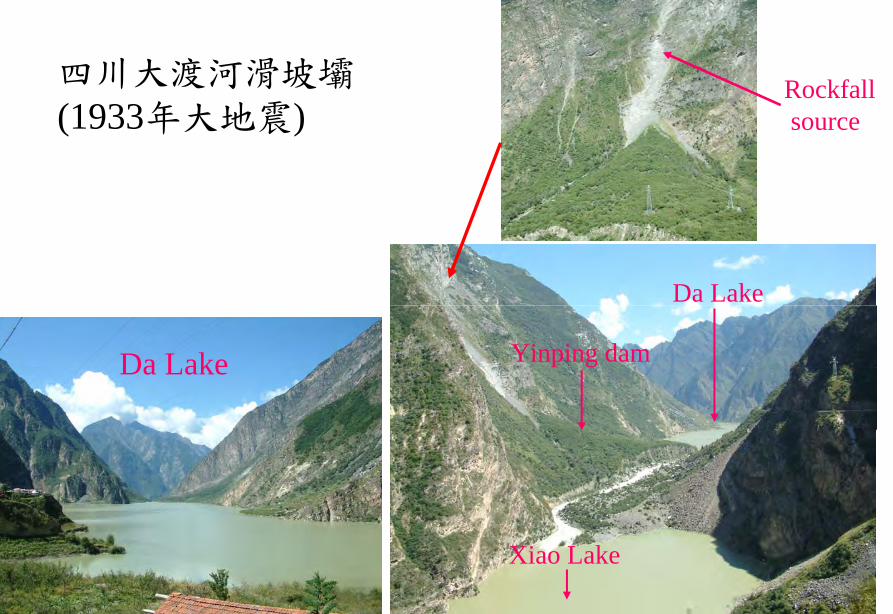
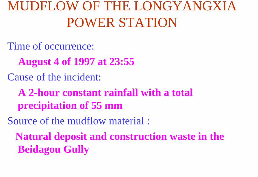
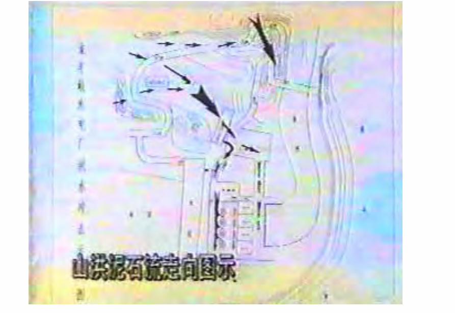
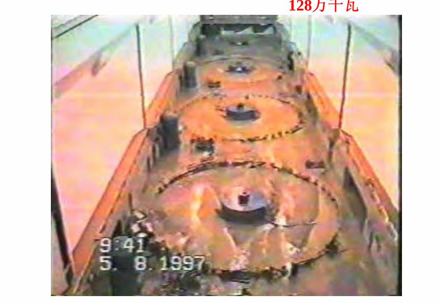
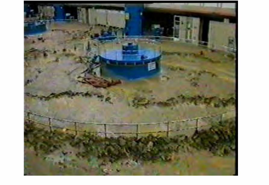
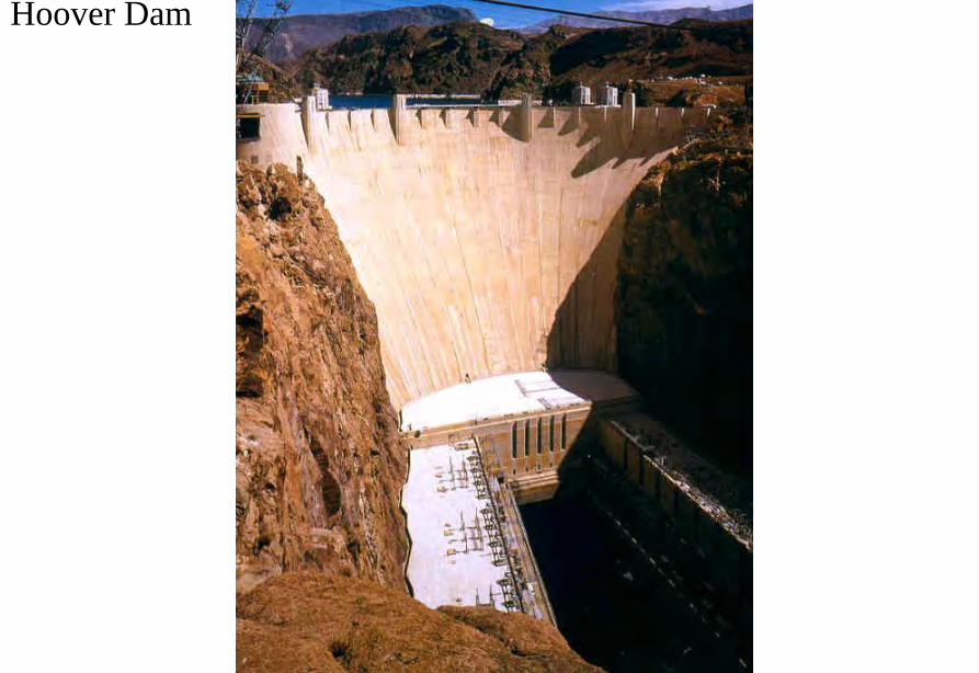
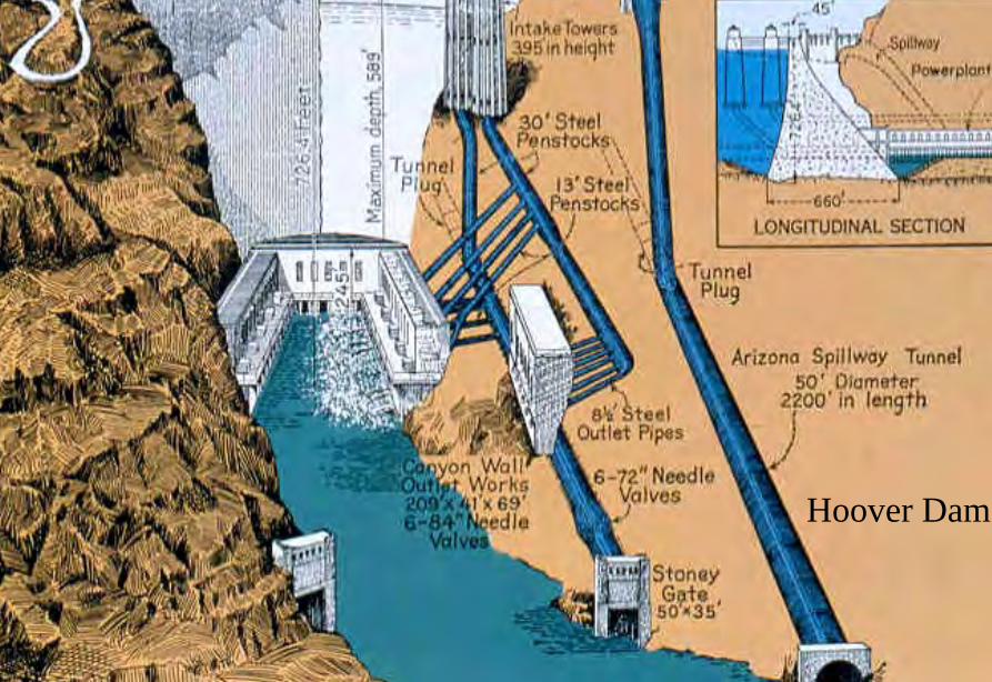
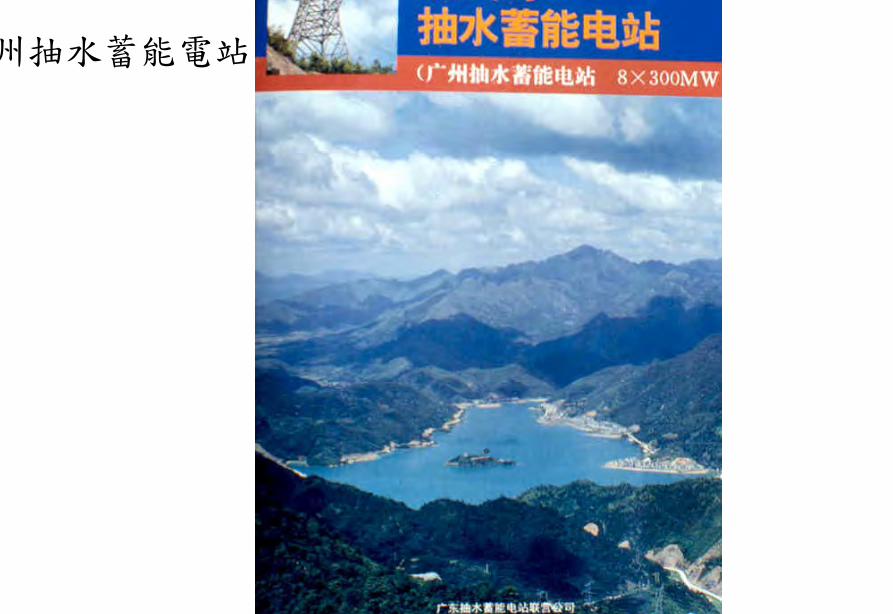
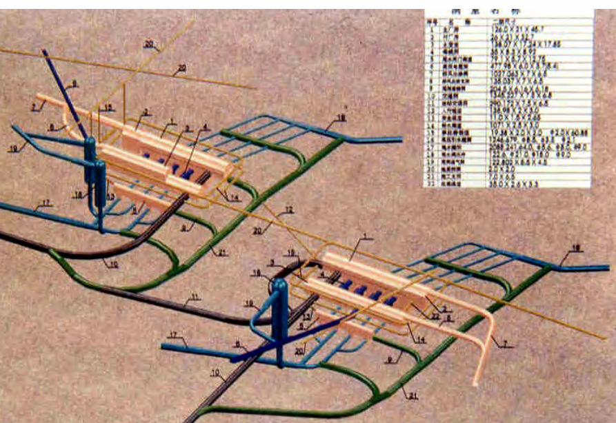
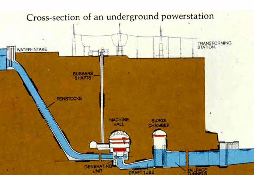
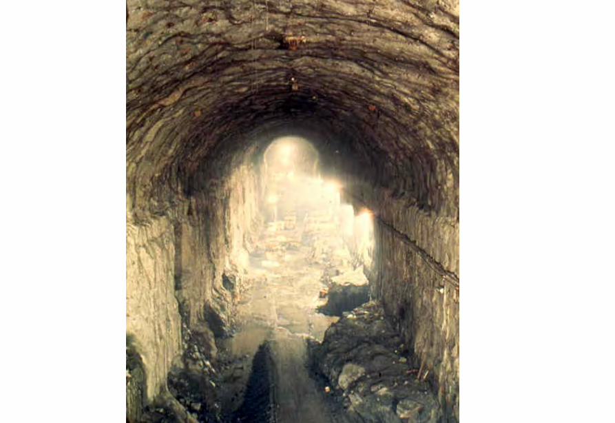
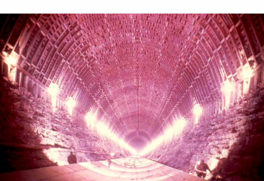
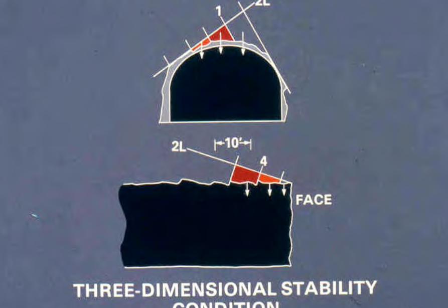
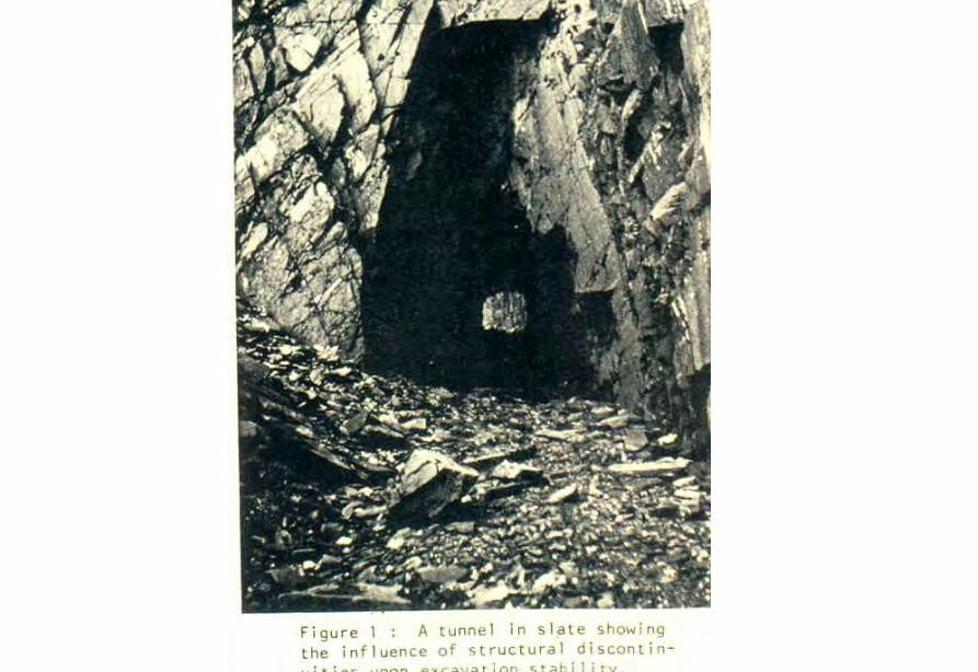
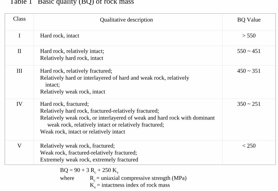
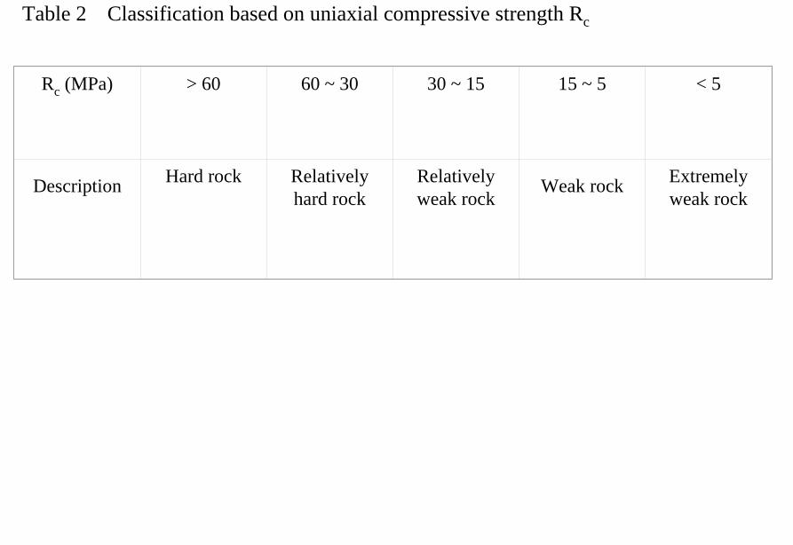
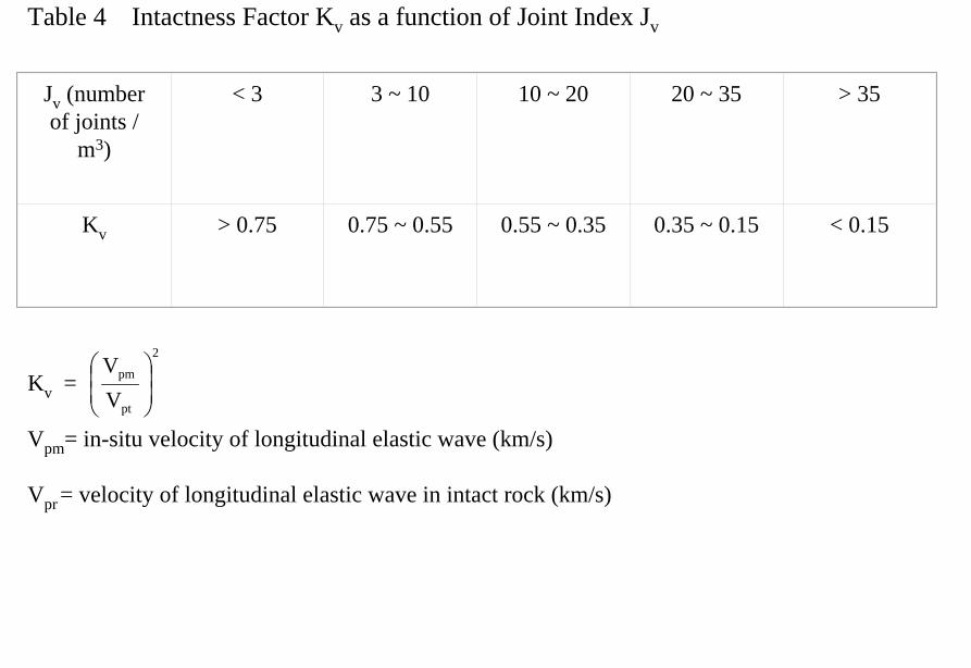
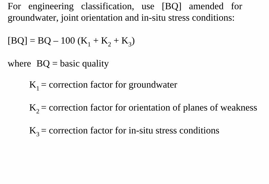
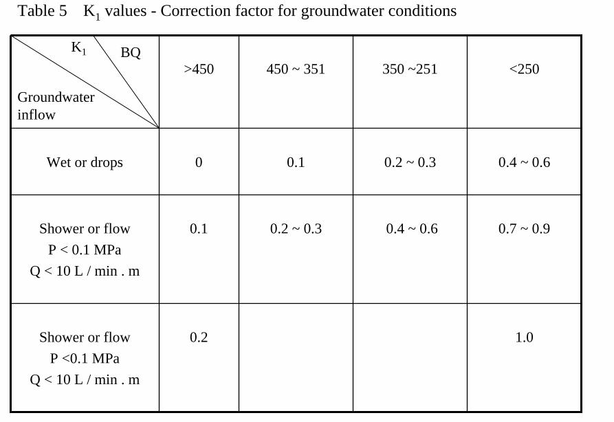
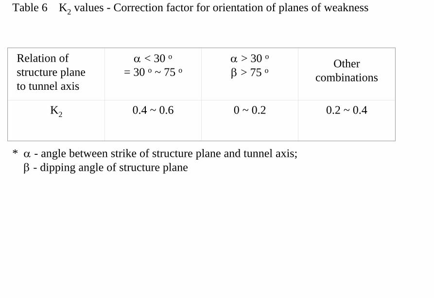
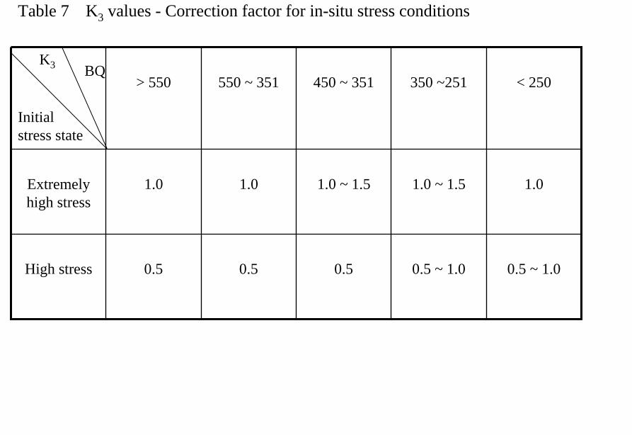
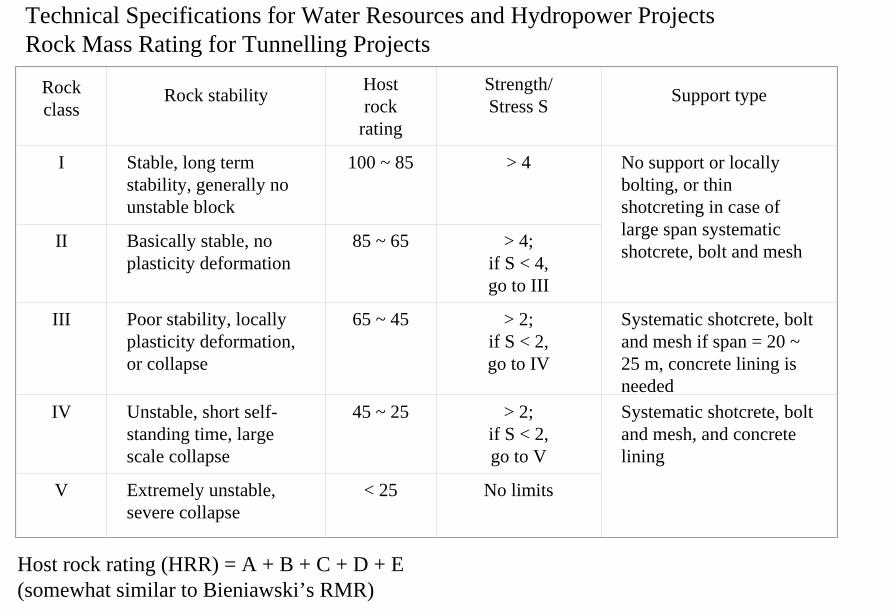
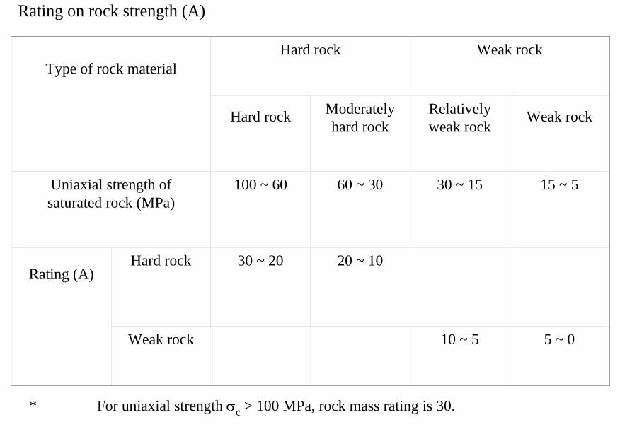
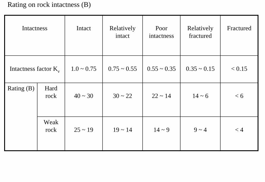
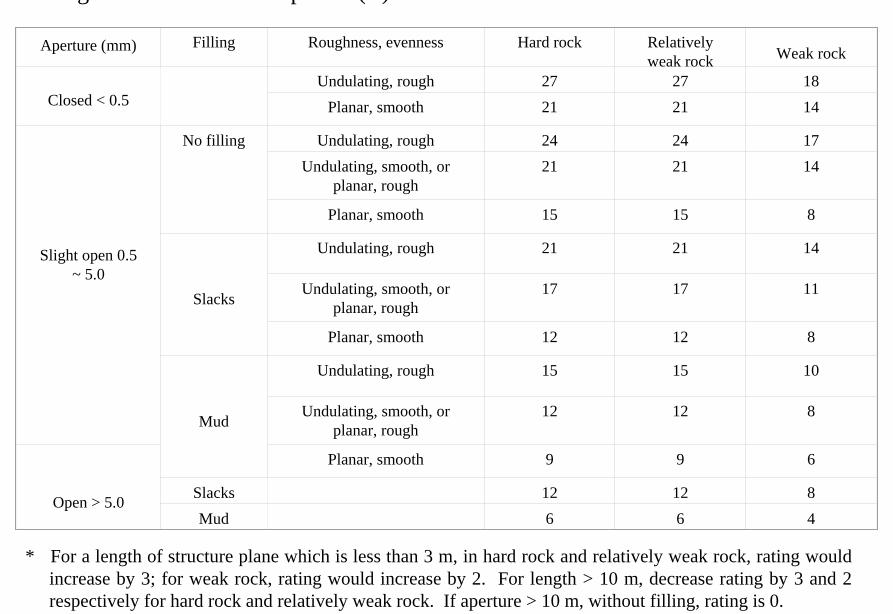
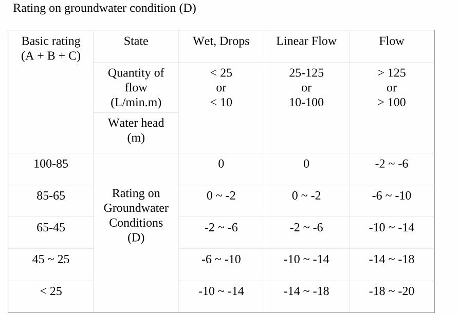
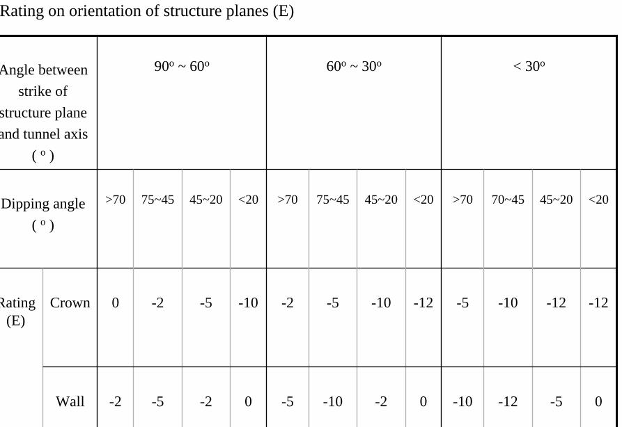
Er Tan Dam
Er Tan Dam
Er Tan Dam Layout
Er Tan Dam Layout
Er Tan Under Construction
Er Tan Under Construction
Er Tan Underground Power House
Er Tan Underground Power House
Er Tan Diversion Tunnel
Er Tan Diversion Tunnel
Er Tan Rock Discing
Er Tan Rock Discing
Er Tan Geostress
Er Tan Geostress(kgcm2)
Strain Energy Approach to Modelling Rock Squeeze Problems
For a virtual displacement δ e
Work Done = Force x Displacement = Feδ e = (δ e)TFe
where Fe = corresponding nodal force Strain energy recovered from unit volume of rock = Stress x Strain = σ ε = ε Tσ = ([B] δ e)T ([D]ε ) = (δ e)T[B][D] ε Work Done = Strain Energy Released (δ e)TFe = (δ e)T int vol [B]T[D] ε dv
or Fe = int vol [B]T[D] ε dv
Some Features of Chinese Hydro Projects
bull Same design framework as in the Westbull Very detailed site investigationsbull Including numerous aditsbull Sometimes leads to significant cost savingsbull (eg Ertan dam allowed to be founded on Class III
rock instead of Class II as called for by Design Standard
bull Strong emphasis on geology and rock mass structure studies
bull Very detailed analysis including numerical modelling AI etc
青海龍羊峽
青海 黃河 李家峽 拱壩壩址
青海 李家峽
探洞
滑面
滑面
李家峽水庫 老滑坡體
剖面
電力需求增長
水電資源
Schematic Map of Hydropower Stations of 1GW and above in Operation or Under Construction
Jin Sha River Hydro Power
南水北調三線
Method of Generation Pros Cons
Capital Construction Cost
(Ratio) Fuel Cost
Fossil
bull Short construction period (2-3 years)
bull Easy to start up
bull Air pollution bull Ashsludge
disposal 1 Relatively high
Hydraulic
bull Longer construction period (gt 5 years)
bull Resettlement of affected population
bull Preservation of cultural amp historic relics
2
Nuclear
bull Relatively long construction period (ge 10 years)
bull Nuclear safety concern
bull Nuclear waste disposal needs
5 Relatively low
Other generation methods solar wind biomass etc
The Joy of being a Hydro Project Engineer
bull Free helicopter jet rides(safe most of the time)
bull Exotic places with breathtaking scenerysceneryand colorful folklore(no tourists around no phone calls etc)
攔路酒(四川 涼山)
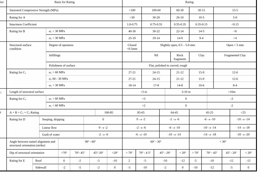
Er Tan Dam Layout
Er Tan Dam Layout
Er Tan Under Construction
Er Tan Under Construction
Er Tan Underground Power House
Er Tan Underground Power House
Er Tan Diversion Tunnel
Er Tan Diversion Tunnel
Er Tan Rock Discing
Er Tan Rock Discing
Er Tan Geostress
Er Tan Geostress(kgcm2)
Strain Energy Approach to Modelling Rock Squeeze Problems
For a virtual displacement δ e
Work Done = Force x Displacement = Feδ e = (δ e)TFe
where Fe = corresponding nodal force Strain energy recovered from unit volume of rock = Stress x Strain = σ ε = ε Tσ = ([B] δ e)T ([D]ε ) = (δ e)T[B][D] ε Work Done = Strain Energy Released (δ e)TFe = (δ e)T int vol [B]T[D] ε dv
or Fe = int vol [B]T[D] ε dv
Some Features of Chinese Hydro Projects
bull Same design framework as in the Westbull Very detailed site investigationsbull Including numerous aditsbull Sometimes leads to significant cost savingsbull (eg Ertan dam allowed to be founded on Class III
rock instead of Class II as called for by Design Standard
bull Strong emphasis on geology and rock mass structure studies
bull Very detailed analysis including numerical modelling AI etc
青海龍羊峽
青海 黃河 李家峽 拱壩壩址
青海 李家峽
探洞
滑面
滑面
李家峽水庫 老滑坡體
剖面
電力需求增長
水電資源
Schematic Map of Hydropower Stations of 1GW and above in Operation or Under Construction
Jin Sha River Hydro Power
南水北調三線
Method of Generation Pros Cons
Capital Construction Cost
(Ratio) Fuel Cost
Fossil
bull Short construction period (2-3 years)
bull Easy to start up
bull Air pollution bull Ashsludge
disposal 1 Relatively high
Hydraulic
bull Longer construction period (gt 5 years)
bull Resettlement of affected population
bull Preservation of cultural amp historic relics
2
Nuclear
bull Relatively long construction period (ge 10 years)
bull Nuclear safety concern
bull Nuclear waste disposal needs
5 Relatively low
Other generation methods solar wind biomass etc
The Joy of being a Hydro Project Engineer
bull Free helicopter jet rides(safe most of the time)
bull Exotic places with breathtaking scenerysceneryand colorful folklore(no tourists around no phone calls etc)
攔路酒(四川 涼山)
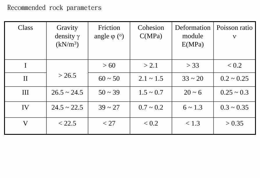
Er Tan Under Construction
Er Tan Under Construction
Er Tan Underground Power House
Er Tan Underground Power House
Er Tan Diversion Tunnel
Er Tan Diversion Tunnel
Er Tan Rock Discing
Er Tan Rock Discing
Er Tan Geostress
Er Tan Geostress(kgcm2)
Strain Energy Approach to Modelling Rock Squeeze Problems
For a virtual displacement δ e
Work Done = Force x Displacement = Feδ e = (δ e)TFe
where Fe = corresponding nodal force Strain energy recovered from unit volume of rock = Stress x Strain = σ ε = ε Tσ = ([B] δ e)T ([D]ε ) = (δ e)T[B][D] ε Work Done = Strain Energy Released (δ e)TFe = (δ e)T int vol [B]T[D] ε dv
or Fe = int vol [B]T[D] ε dv
Some Features of Chinese Hydro Projects
bull Same design framework as in the Westbull Very detailed site investigationsbull Including numerous aditsbull Sometimes leads to significant cost savingsbull (eg Ertan dam allowed to be founded on Class III
rock instead of Class II as called for by Design Standard
bull Strong emphasis on geology and rock mass structure studies
bull Very detailed analysis including numerical modelling AI etc
青海龍羊峽
青海 黃河 李家峽 拱壩壩址
青海 李家峽
探洞
滑面
滑面
李家峽水庫 老滑坡體
剖面
電力需求增長
水電資源
Schematic Map of Hydropower Stations of 1GW and above in Operation or Under Construction
Jin Sha River Hydro Power
南水北調三線
Method of Generation Pros Cons
Capital Construction Cost
(Ratio) Fuel Cost
Fossil
bull Short construction period (2-3 years)
bull Easy to start up
bull Air pollution bull Ashsludge
disposal 1 Relatively high
Hydraulic
bull Longer construction period (gt 5 years)
bull Resettlement of affected population
bull Preservation of cultural amp historic relics
2
Nuclear
bull Relatively long construction period (ge 10 years)
bull Nuclear safety concern
bull Nuclear waste disposal needs
5 Relatively low
Other generation methods solar wind biomass etc
The Joy of being a Hydro Project Engineer
bull Free helicopter jet rides(safe most of the time)
bull Exotic places with breathtaking scenerysceneryand colorful folklore(no tourists around no phone calls etc)
攔路酒(四川 涼山)
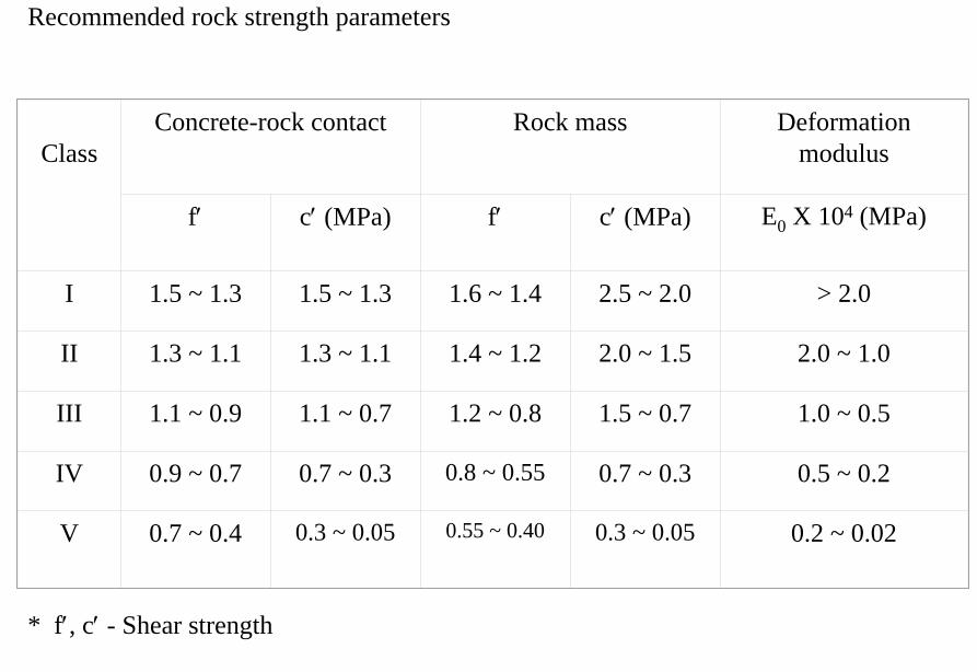
Er Tan Underground Power House
Er Tan Underground Power House
Er Tan Diversion Tunnel
Er Tan Diversion Tunnel
Er Tan Rock Discing
Er Tan Rock Discing
Er Tan Geostress
Er Tan Geostress(kgcm2)
Strain Energy Approach to Modelling Rock Squeeze Problems
For a virtual displacement δ e
Work Done = Force x Displacement = Feδ e = (δ e)TFe
where Fe = corresponding nodal force Strain energy recovered from unit volume of rock = Stress x Strain = σ ε = ε Tσ = ([B] δ e)T ([D]ε ) = (δ e)T[B][D] ε Work Done = Strain Energy Released (δ e)TFe = (δ e)T int vol [B]T[D] ε dv
or Fe = int vol [B]T[D] ε dv
Some Features of Chinese Hydro Projects
bull Same design framework as in the Westbull Very detailed site investigationsbull Including numerous aditsbull Sometimes leads to significant cost savingsbull (eg Ertan dam allowed to be founded on Class III
rock instead of Class II as called for by Design Standard
bull Strong emphasis on geology and rock mass structure studies
bull Very detailed analysis including numerical modelling AI etc
青海龍羊峽
青海 黃河 李家峽 拱壩壩址
青海 李家峽
探洞
滑面
滑面
李家峽水庫 老滑坡體
剖面
電力需求增長
水電資源
Schematic Map of Hydropower Stations of 1GW and above in Operation or Under Construction
Jin Sha River Hydro Power
南水北調三線
Method of Generation Pros Cons
Capital Construction Cost
(Ratio) Fuel Cost
Fossil
bull Short construction period (2-3 years)
bull Easy to start up
bull Air pollution bull Ashsludge
disposal 1 Relatively high
Hydraulic
bull Longer construction period (gt 5 years)
bull Resettlement of affected population
bull Preservation of cultural amp historic relics
2
Nuclear
bull Relatively long construction period (ge 10 years)
bull Nuclear safety concern
bull Nuclear waste disposal needs
5 Relatively low
Other generation methods solar wind biomass etc
The Joy of being a Hydro Project Engineer
bull Free helicopter jet rides(safe most of the time)
bull Exotic places with breathtaking scenerysceneryand colorful folklore(no tourists around no phone calls etc)
攔路酒(四川 涼山)
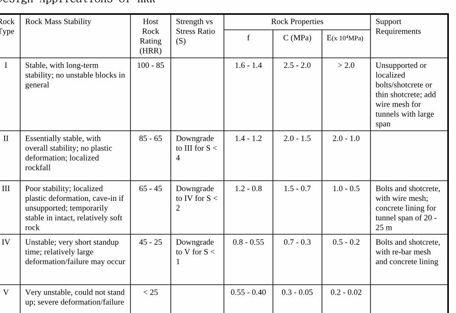
Er Tan Diversion Tunnel
Er Tan Diversion Tunnel
Er Tan Rock Discing
Er Tan Rock Discing
Er Tan Geostress
Er Tan Geostress(kgcm2)
Strain Energy Approach to Modelling Rock Squeeze Problems
For a virtual displacement δ e
Work Done = Force x Displacement = Feδ e = (δ e)TFe
where Fe = corresponding nodal force Strain energy recovered from unit volume of rock = Stress x Strain = σ ε = ε Tσ = ([B] δ e)T ([D]ε ) = (δ e)T[B][D] ε Work Done = Strain Energy Released (δ e)TFe = (δ e)T int vol [B]T[D] ε dv
or Fe = int vol [B]T[D] ε dv
Some Features of Chinese Hydro Projects
bull Same design framework as in the Westbull Very detailed site investigationsbull Including numerous aditsbull Sometimes leads to significant cost savingsbull (eg Ertan dam allowed to be founded on Class III
rock instead of Class II as called for by Design Standard
bull Strong emphasis on geology and rock mass structure studies
bull Very detailed analysis including numerical modelling AI etc
青海龍羊峽
青海 黃河 李家峽 拱壩壩址
青海 李家峽
探洞
滑面
滑面
李家峽水庫 老滑坡體
剖面
電力需求增長
水電資源
Schematic Map of Hydropower Stations of 1GW and above in Operation or Under Construction
Jin Sha River Hydro Power
南水北調三線
Method of Generation Pros Cons
Capital Construction Cost
(Ratio) Fuel Cost
Fossil
bull Short construction period (2-3 years)
bull Easy to start up
bull Air pollution bull Ashsludge
disposal 1 Relatively high
Hydraulic
bull Longer construction period (gt 5 years)
bull Resettlement of affected population
bull Preservation of cultural amp historic relics
2
Nuclear
bull Relatively long construction period (ge 10 years)
bull Nuclear safety concern
bull Nuclear waste disposal needs
5 Relatively low
Other generation methods solar wind biomass etc
The Joy of being a Hydro Project Engineer
bull Free helicopter jet rides(safe most of the time)
bull Exotic places with breathtaking scenerysceneryand colorful folklore(no tourists around no phone calls etc)
攔路酒(四川 涼山)
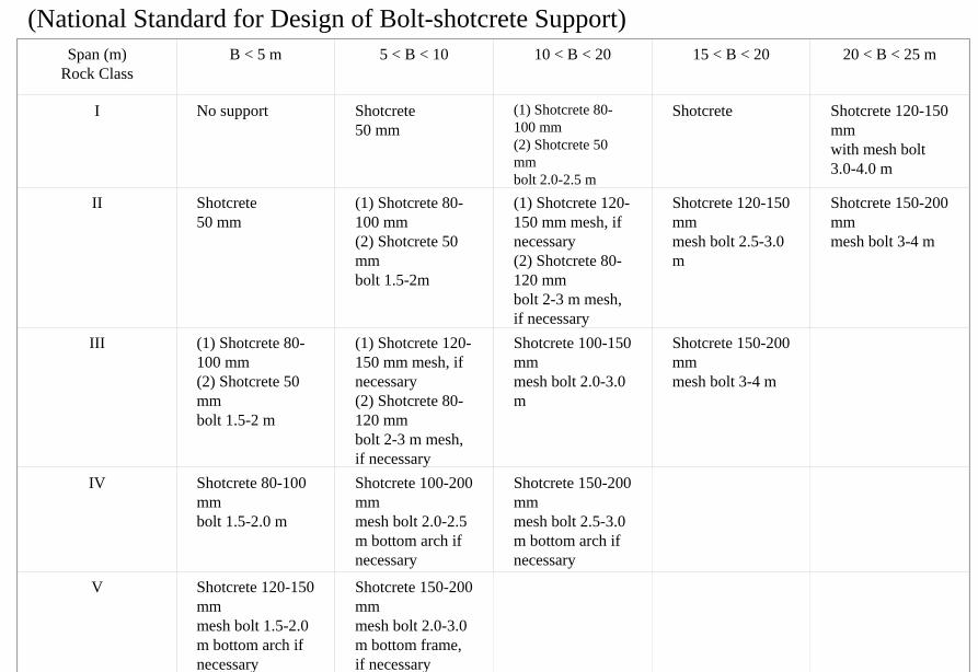
Er Tan Rock Discing
Er Tan Rock Discing
Er Tan Geostress
Er Tan Geostress(kgcm2)
Strain Energy Approach to Modelling Rock Squeeze Problems
For a virtual displacement δ e
Work Done = Force x Displacement = Feδ e = (δ e)TFe
where Fe = corresponding nodal force Strain energy recovered from unit volume of rock = Stress x Strain = σ ε = ε Tσ = ([B] δ e)T ([D]ε ) = (δ e)T[B][D] ε Work Done = Strain Energy Released (δ e)TFe = (δ e)T int vol [B]T[D] ε dv
or Fe = int vol [B]T[D] ε dv
Some Features of Chinese Hydro Projects
bull Same design framework as in the Westbull Very detailed site investigationsbull Including numerous aditsbull Sometimes leads to significant cost savingsbull (eg Ertan dam allowed to be founded on Class III
rock instead of Class II as called for by Design Standard
bull Strong emphasis on geology and rock mass structure studies
bull Very detailed analysis including numerical modelling AI etc
青海龍羊峽
青海 黃河 李家峽 拱壩壩址
青海 李家峽
探洞
滑面
滑面
李家峽水庫 老滑坡體
剖面
電力需求增長
水電資源
Schematic Map of Hydropower Stations of 1GW and above in Operation or Under Construction
Jin Sha River Hydro Power
南水北調三線
Method of Generation Pros Cons
Capital Construction Cost
(Ratio) Fuel Cost
Fossil
bull Short construction period (2-3 years)
bull Easy to start up
bull Air pollution bull Ashsludge
disposal 1 Relatively high
Hydraulic
bull Longer construction period (gt 5 years)
bull Resettlement of affected population
bull Preservation of cultural amp historic relics
2
Nuclear
bull Relatively long construction period (ge 10 years)
bull Nuclear safety concern
bull Nuclear waste disposal needs
5 Relatively low
Other generation methods solar wind biomass etc
The Joy of being a Hydro Project Engineer
bull Free helicopter jet rides(safe most of the time)
bull Exotic places with breathtaking scenerysceneryand colorful folklore(no tourists around no phone calls etc)
攔路酒(四川 涼山)
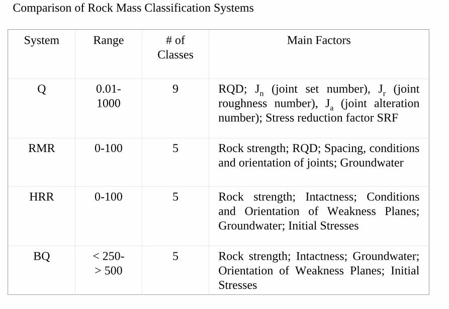
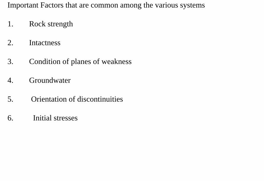
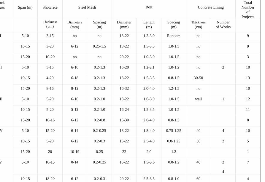
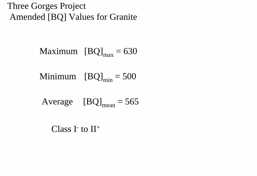
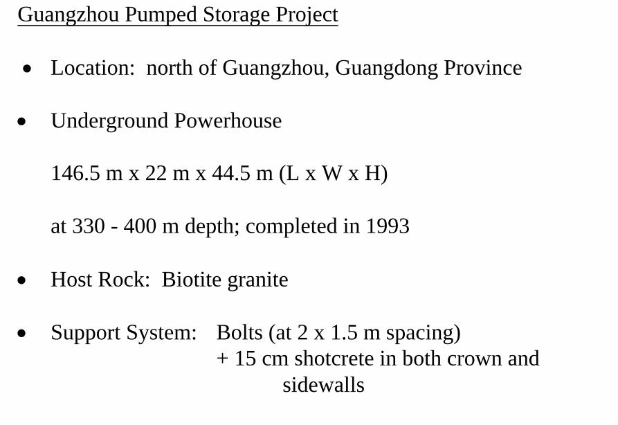
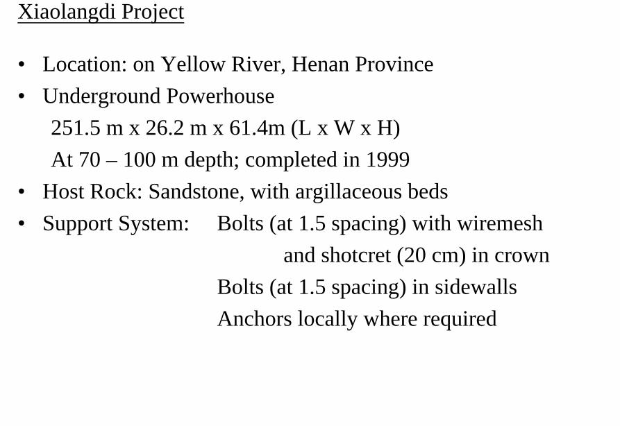
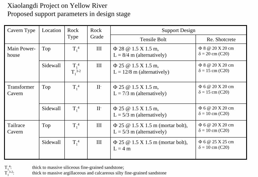
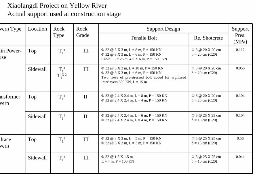
滑面
滑面
李家峽水庫 老滑坡體
剖面
電力需求增長
水電資源
Schematic Map of Hydropower Stations of 1GW and above in Operation or Under Construction
Jin Sha River Hydro Power
南水北調三線
Method of Generation Pros Cons
Capital Construction Cost
(Ratio) Fuel Cost
Fossil
bull Short construction period (2-3 years)
bull Easy to start up
bull Air pollution bull Ashsludge
disposal 1 Relatively high
Hydraulic
bull Longer construction period (gt 5 years)
bull Resettlement of affected population
bull Preservation of cultural amp historic relics
2
Nuclear
bull Relatively long construction period (ge 10 years)
bull Nuclear safety concern
bull Nuclear waste disposal needs
5 Relatively low
Other generation methods solar wind biomass etc
The Joy of being a Hydro Project Engineer
bull Free helicopter jet rides(safe most of the time)
bull Exotic places with breathtaking scenerysceneryand colorful folklore(no tourists around no phone calls etc)
攔路酒(四川 涼山)
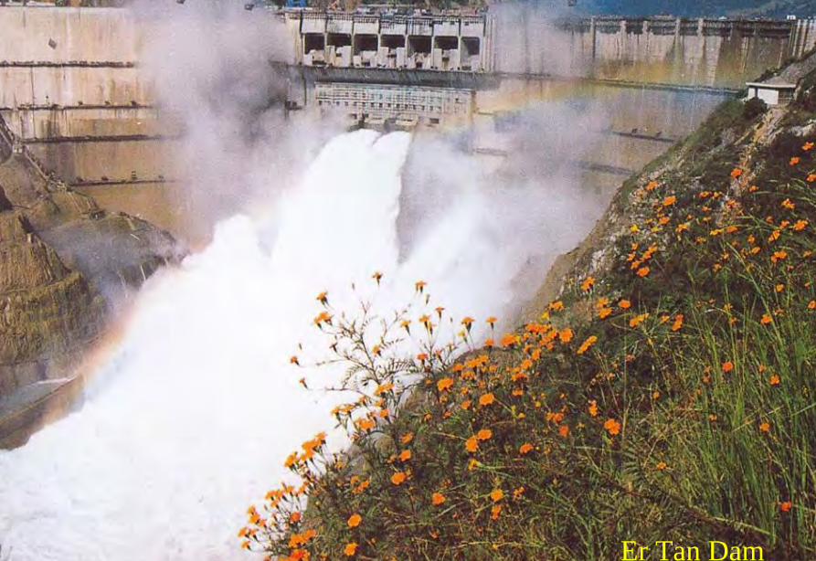
滑面
李家峽水庫 老滑坡體
剖面
電力需求增長
水電資源
Schematic Map of Hydropower Stations of 1GW and above in Operation or Under Construction
Jin Sha River Hydro Power
南水北調三線
Method of Generation Pros Cons
Capital Construction Cost
(Ratio) Fuel Cost
Fossil
bull Short construction period (2-3 years)
bull Easy to start up
bull Air pollution bull Ashsludge
disposal 1 Relatively high
Hydraulic
bull Longer construction period (gt 5 years)
bull Resettlement of affected population
bull Preservation of cultural amp historic relics
2
Nuclear
bull Relatively long construction period (ge 10 years)
bull Nuclear safety concern
bull Nuclear waste disposal needs
5 Relatively low
Other generation methods solar wind biomass etc
The Joy of being a Hydro Project Engineer
bull Free helicopter jet rides(safe most of the time)
bull Exotic places with breathtaking scenerysceneryand colorful folklore(no tourists around no phone calls etc)
攔路酒(四川 涼山)
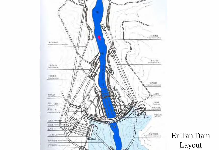
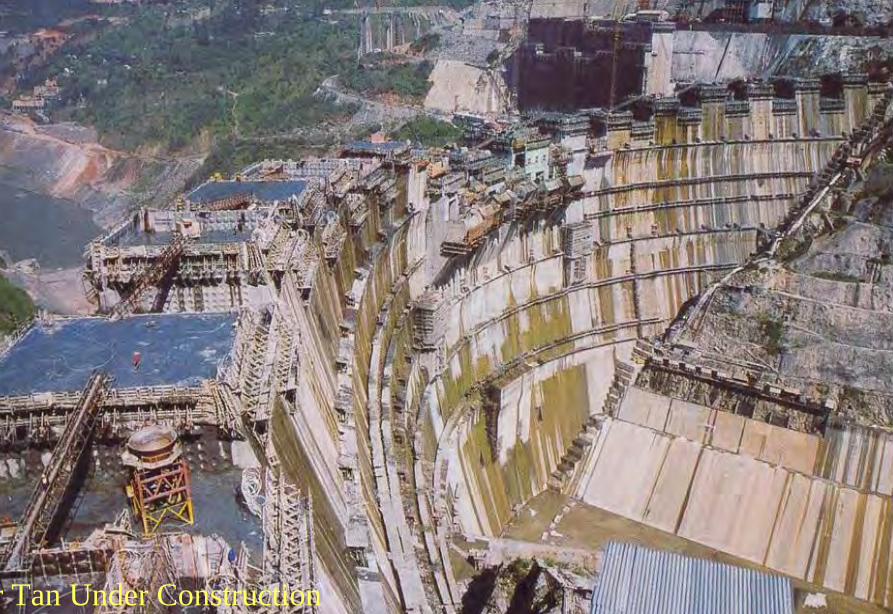
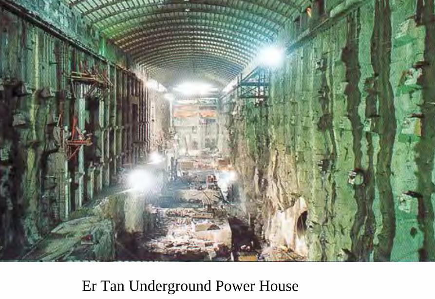
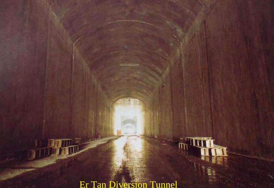
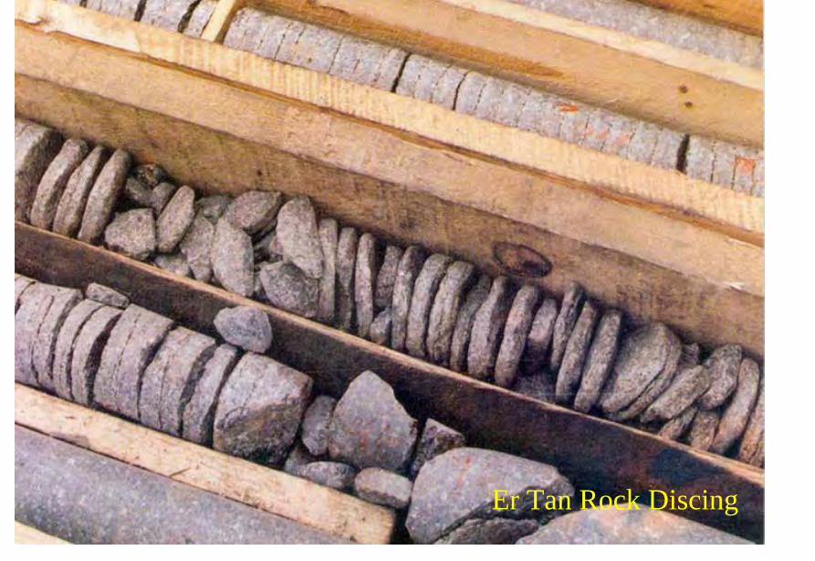
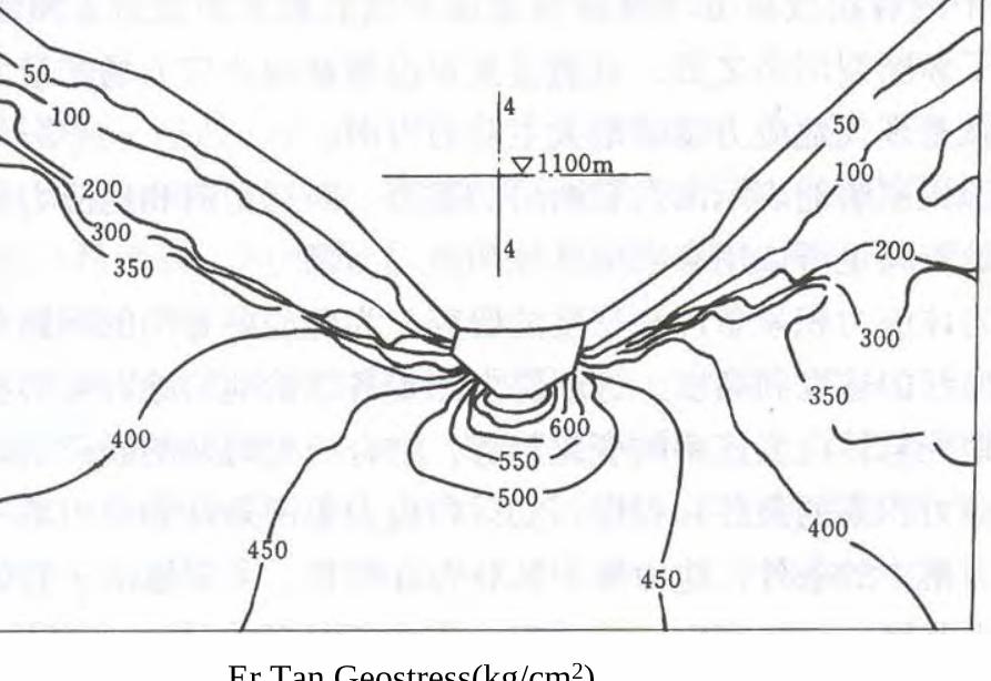
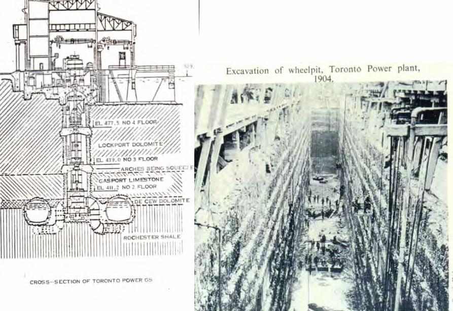
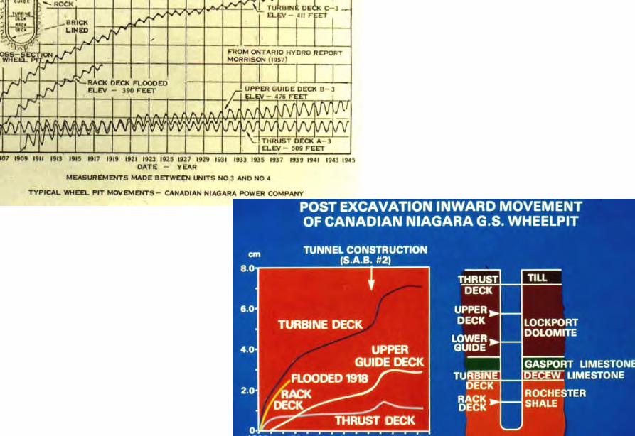
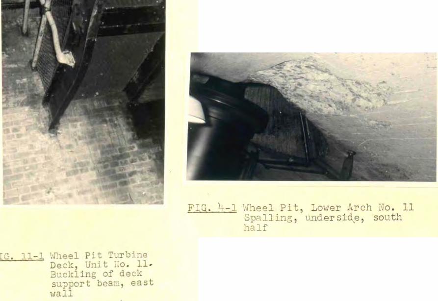
The Joy of being a Hydro Project Engineer
bull Free helicopter jet rides(safe most of the time)
bull Exotic places with breathtaking scenerysceneryand colorful folklore(no tourists around no phone calls etc)
攔路酒(四川 涼山)
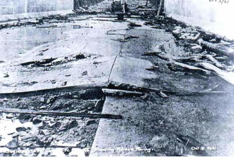
攔路酒(四川 涼山)