Embed Size (px)
Citation preview
Documentation also available on CD and D-Link Website
Getting Started GuideErste SchritteGuide de démarrageGuida introduttivaGuía de introducciónКраткое руководство пользователяGuia inicial快速安裝指南
Petunjuk Pemasangan本製品のご利用にあたって
快速安裝指南
Getting Started Guide For D-Link SmartPro Switch
2
EN
GLI
SH
About This GuideThis guide gives step-by-step instructions for setting up all D-Link SmartPro switches and relative Warranty, Safety, Regulatory, and Environment Notice. Please note that the model you have purchased may appear slightly different from those shown in the illustrations.
For more detailed information about your switch, its components, making network connections, and technical specifications, please refer to the User’s Guide included with your switch.
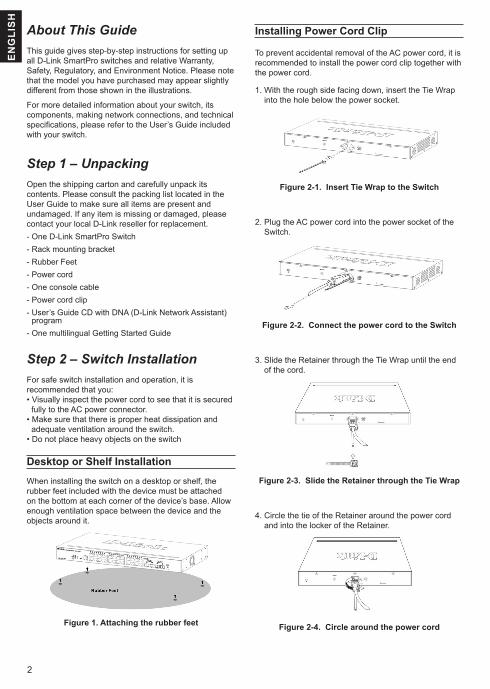
Step 1 – UnpackingOpen the shipping carton and carefully unpack its contents. Please consult the packing list located in the User Guide to make sure all items are present and undamaged. If any item is missing or damaged, please contact your local D-Link reseller for replacement.- One D-Link SmartPro Switch - Rack mounting bracket- Rubber Feet- Power cord- One console cable- Power cord clip- User’s Guide CD with DNA (D-Link Network Assistant)
program- One multilingual Getting Started Guide
Step 2 – Switch InstallationFor safe switch installation and operation, it is recommended that you:• Visually inspect the power cord to see that it is secured
fully to the AC power connector.• Make sure that there is proper heat dissipation and
adequate ventilation around the switch.• Do not place heavy objects on the switch
Desktop or Shelf Installation
When installing the switch on a desktop or shelf, the rubber feet included with the device must be attached on the bottom at each corner of the device’s base. Allow enough ventilation space between the device and the objects around it.
Figure 1. Attaching the rubber feet
Installing Power Cord Clip
To prevent accidental removal of the AC power cord, it is recommended to install the power cord clip together with the power cord.
1. With the rough side facing down, insert the Tie Wrap into the hole below the power socket.
Figure 2-1. Insert Tie Wrap to the Switch
2. Plug the AC power cord into the power socket of the Switch.
Figure 2-2. Connect the power cord to the Switch
3. Slide the Retainer through the Tie Wrap until the end of the cord.
Figure 2-3. Slide the Retainer through the Tie Wrap
4. Circle the tie of the Retainer around the power cord and into the locker of the Retainer.
Figure 2-4. Circle around the power cord
3
EN
GLIS
H
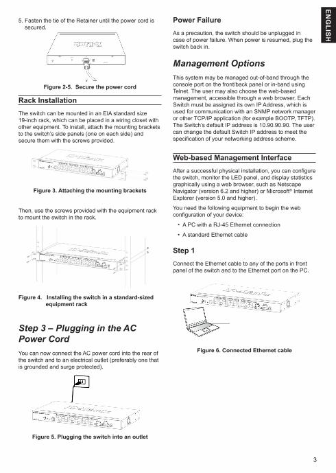
5. Fasten the tie of the Retainer until the power cord is secured.
Figure 2-5. Secure the power cord
Rack InstallationThe switch can be mounted in an EIA standard size 19-inch rack, which can be placed in a wiring closet with other equipment. To install, attach the mounting brackets to the switch’s side panels (one on each side) and secure them with the screws provided.
Figure 3. Attaching the mounting brackets
Then, use the screws provided with the equipment rack to mount the switch in the rack.
Figure 4. Installing the switch in a standard-sized equipment rack
Step 3 – Plugging in the AC Power CordYou can now connect the AC power cord into the rear of the switch and to an electrical outlet (preferably one that is grounded and surge protected).
Figure 5. Plugging the switch into an outlet
Power FailureAs a precaution, the switch should be unplugged in case of power failure. When power is resumed, plug the switch back in.
Management OptionsThis system may be managed out-of-band through the console port on the front/back panel or in-band using Telnet. The user may also choose the web-based management, accessible through a web browser. Each Switch must be assigned its own IP Address, which is used for communication with an SNMP network manager or other TCP/IP application (for example BOOTP, TFTP). The Switch’s default IP address is 10.90.90.90. The user can change the default Switch IP address to meet the specification of your networking address scheme.
Web-based Management InterfaceAfter a successful physical installation, you can configure the switch, monitor the LED panel, and display statistics graphically using a web browser, such as Netscape Navigator (version 6.2 and higher) or Microsoft® Internet Explorer (version 5.0 and higher).
You need the following equipment to begin the web configuration of your device:
• A PC with a RJ-45 Ethernet connection
• A standard Ethernet cable
Step 1Connect the Ethernet cable to any of the ports in front panel of the switch and to the Ethernet port on the PC.
Figure 6. Connected Ethernet cable
4
EN
GLI
SH
DNA (D-Link Network Assistant)
The DNA (D-Link Network Assistant) included on the installation CD is a program for discovering Smart Switches with the same L2 network segment connected to your PC. This tool can support windows 2000, XP, Vista, and Windows 7. There are two options for the installation of DNA (D-Link Network Assistant), one is through the autorun program on the installation CD and the other is manual installation.
Option 1: Follow these steps to install the DNA (D-Link Network Assistant) via the autorun program on the installation CD.
1. Insert the CD into your CD-Rom Drive.
2. The autorun program will pop up automatically
3. Simply click on the ”Install DNA (D-Link Network Assistant)” button and an installation wizard will guide you through the process.
4. After successfully installing the DNA, you can find it under Start > Programs > D-Link > DNA.
5. Just connect the SmartPro Switch to the same L2 network segment of your PC and use the DNA (D-Link Network Assistant) to discover the Smart Switches.
Option 2: Follow these steps to install the DNA (D-Link Network Assistant) manually.
1. Insert the Utility CD into your CD-Rom Drive.
2. From the Start menu on the Windows desktop, choose Computer.
3. Double click on your CD-Rom/DVD-Rom Drive to start the autorun menu, or right click on the Drive to open the folder. Select DNA (D-Link Network Assistant) and double click on the setup.exe file.
4. Follow the on-screen instructions to install the utility.
5. Upon completion, go to Start > Programs > D-Link > DNA and open the DNA (D-Link Network Assistant).
6. Just connect the SmartPro Switch to the same L2 network segment of your PC and use the DNA (D-Link Network Assistant) to discover the Smart Switches.
For detailed information of DNA, please refer the user manual.
Connecting The Console PortTo connect to the serial port, a special Console Cable must be used. This cable is included with this product’s packaging. The cable referred to as an RS-232 to RJ-45 connector cable specifically pinned to connect to this switch’s serial port by using the correct pin configuration.
To connect to the console port of the Switch, use the following steps:
Step 2
In order to login and configure the switch via an Ethernet connection, the PC must have an IP address in the same range as the switch. For example, if the switch has an IP address of 10.90.90.90, the PC should have an IP address of 10.x.y.z (where x/y is a number between 0 ~ 254 and z is a number between 1 ~254), and a subnet mask of 255.0.0.0.
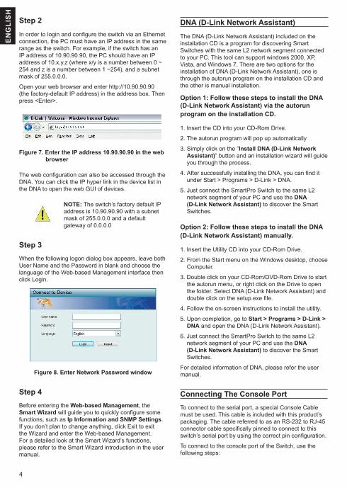
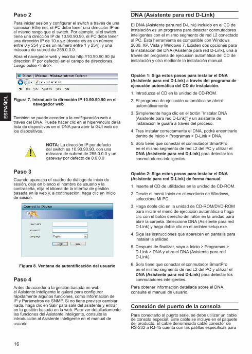
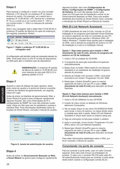
Open your web browser and enter http://10.90.90.90 (the factory-default IP address) in the address box. Then press <Enter>.
Figure 7. Enter the IP address 10.90.90.90 in the web browser
The web configuration can also be accessed through the DNA. You can click the IP hyper link in the device list in the DNA to open the web GUI of devices.
NOTE: The switch’s factory default IP address is 10.90.90.90 with a subnet mask of 255.0.0.0 and a default gateway of 0.0.0.0
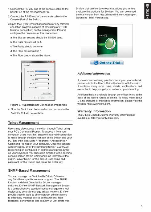
Step 3When the following logon dialog box appears, leave both User Name and the Password in blank and choose the language of the Web-based Management interface then click Login.
Figure 8. Enter Network Password window
Step 4Before entering the Web-based Management, the Smart Wizard will guide you to quickly configure some functions, such as Ip Information and SNMP Settings. If you don’t plan to change anything, click Exit to exit the Wizard and enter the Web-based Management. For a detailed look at the Smart Wizard’s functions, please refer to the Smart Wizard introduction in the user manual.
5
EN
GLIS
H
1. Connect the RS-232 end of the console cable to the Serial Port of the management PC.
2. Connect the RJ-45 end of the console cable to the Console Port of the Switch.
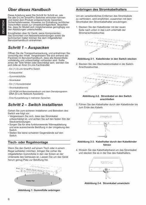
3. Open the HyperTerminal application (or any terminal emulation program capable of emulating a VT-100 terminal connection) on the management PC and configure the Properies of this connection.
a.The Bits per second should be 115200 baud.
b.The Data bits should be 8.
c.The Parity should be None.
d.The Stop bits should be 1.
e.The Flow control should be None.
Figure 9. Hyperterminal Connection Properties
4. Now the Switch can be turned on and access to the Switch’s CLI will be available.
Telnet ManagementUsers may also access the switch through Telnet using your PC’s Command Prompt. To access it from your computer, users must first ensure that a valid connection is made through the Ethernet port of the Switch and your PC, and then click Start > Programs > Accessories > Command Prompt on your computer. Once the console window opens, enter the command telnet 10.90.90.90 (depending on configured IP address) and press Enter on your keyboard. You should be directed to the opening console screen for the Command Line Interface of the switch, leave “black” for the default user name and password for the Switch and press the Enter key.
SNMP-Based ManagementYou can manage the Switch with D-Link D-View or any SNMP-compatible console program. The SNMP function is default Disabled for D-Link managed switches. D-View SNMP Network Management System is a comprehensive standard-based management tool designed to centrally manage critical network. D-View provides useful tools to allow network administrators to effectively manage device configurations, fault tolerance, performance and security. D-Link offers free
Additional Information
If you are encountering problems setting up your network, please refer to the User’s Guide that came with the switch. It contains many more rules, charts, explanations and examples to help you get your network up and running.
Additional help is available through our offices listed at the back of the User’s Guide or online. To know more about D-Link products or marketing information, please visit the website http://www.dlink.com.
Warranty Information The D-Link Limited Lifetime Warranty information is available at http://warranty.dlink.com/
D-View trial version download that allows you to free evaluate the products for 30 days. You can download the trial version from http://dview.dlink.com.tw/support_Download_Trial_Version.asp.
6
DE
UT
SC
H
Über dieses HandbuchDiese Anleitung weist Sie Schritt für Schritt an, wie Sie alle D-Link SmartPro Switches einrichten können und bietet dem Produkt entsprechende Garantien, Sicherheitshinweise, Hinweise zur Einhaltung rechtlicher Vorschriften sowie zur Umweltverträglichkeit. Beachten Sie, dass Ihr Modell sich möglicherweise geringfügig von den Abbildungen unterscheidet. Einzelheiten über Ihr Gerät, seine Komponenten, das Einrichten von Netzwerkverbindungen sowie die technischen Daten können Sie dem mitgelieferten Benutzerhandbuch entnehmen.
Schritt 1 – AuspackenÖffnen Sie die Transportverpackung, und entnehmen Sie vorsichtig den Inhalt. Vergewissern Sie sich anhand der Packliste im Benutzerhandbuch, dass alle Bestandteile vollständig und unbeschädigt vorhanden sind. Sollte eines der Teile fehlen oder beschädigt sein, wenden Sie sich bitte an Ihren D-Link-Fachhändler.- Ein (1) D-Link SmartPro Switch
- Einbauwinkel
- Gummistützfüße
- Stromkabel
- Ein (1) Konsolenkabel
- Stromkabelklemme
- CD-ROM mit Benutzerhandbuch und dem Dienstprogramm DNA (D-Link Network Assistant)
- Eine Kurzanleitung in mehreren Sprachen
Schritt 2 – Switch installierenGehen Sie zum sicheren Installieren und Betreiben des Switch wie folgt vor:• Vergewissern Sie sich, dass das Stromkabel
unbeschädigt ist, und achten Sie auf den festen Sitz der Steckverbindungen.
• Sorgen Sie für eine funktionierende Wärmeableitung und eine ausreichende Belüftung in der Umgebung des Switch.
• Stellen Sie keine schweren Gegenstände auf den Switch.
Tisch- oder Regalmontage
Wenn Sie den Switch auf einem Tisch oder in einem Regal aufstellen möchten, bringen Sie vorher die mitgelieferten Gummifüße in den vier Ecken an der Unterseite des Gehäuses an. Lassen Sie um das Gerät herum genug Platz zur Belüftung frei.
Abbildung 1: Gummifüße anbringen
Anbringen des Stromkabelhalters
Um ein versehentliches Entfernen des Stromkabels zu verhindern, wird empfohlen, zusammen mit dem Stromkabel den Stromkabelhalter anzubringen.
1. Stecken Sie den Kabelbinder mit der rauen Seite nach unten in das Loch unterhalb der Stromanschlussbuchse.
Abbildung 2-1. Kabelbinder in den Switch stecken
2. Stecken Sie das Wechselstromkabel in die Switch-Anschlussbuchse.
Abbildung 2-2. Stromkabel an den Switch anschließen
3. Führen Sie den Kabelhalter durch den Kabelbinder bis zum Ende des Kabels.
Abbildung 2-3. Kabelhalter durch den Kabelbinder führen
4. Wickeln Sie das Kabelhalterband um das Stromkabel und stecken Sie es in die Öse des Kabelhalters.
Abbildung 2-4. Stromkabel umwickeln
7
DE
UT
SC
H
RackmontageDer Switch kann in einem 19-Zoll-Rack (EIA-Standardgröße) montiert und mit weiteren Geräten in einem Verkabelungsschrank installiert werden. Bringen Sie an jedem Seitenblech des Switch einen Einbauwinkel an, und schrauben Sie die Winkel mit den beiliegenden Schrauben fest.
Abbildung 3: Einbauwinkel anbringen
Montieren Sie danach den Switch im Einschub mit den Schrauben, die Sie zu Ihrem Rack erhalten haben.
Abbildung 4: Switch im Standardrack installieren
Schritt 3 – An die Stromversorgung anschließenSchließen Sie das Stromkabel an eine Steckdose (möglichst geerdet und mit Überspannungsschutz) und an den Netzanschluss auf der Rückseite des Switch an.
Abbildung 5: Switch an die Stromversorgung anschließen
5. Ziehen Sie das Zugband der Kabelhalterung fest, bis das Stromkabel sicher und fest angebracht ist.
Abbildung 2-5. Stromkabel sicher befestigen
StromausfallAus Sicherheitsgründen sollten Sie bei einem Stromausfall den Netzstecker ziehen. Ist die Stromversorgung wieder gewährleistet, können Sie den Netzstecker des Switch wieder einstecken.
ManagementoptionenSie können für dieses System eine Out-of-Band-Verwaltung über den Konsolenport der Vorder-/Rückseite oder eine In-Band-Verwaltung mithilfe von Telnet vornehmen. Sie können aber auch das webbasierte Management wählen, auf das Sie über einen Webbrowser zugreifen können. Jedem Switch muss eine eigene IP-Adresse zugewiesen werden, die für die Kommunikation mit einem SNMP-Netzwerkverwaltungsprogramm oder einer anderen TCP/IP-Anwendung (beispielsweise BOOTP, TFTP) verwendet wird. Die standardmäßige IP-Adresse des Switch lautet 10.90.90.90. Sie können die standardmäßige IP-Adresse des Switch gemäß den Anforderungen Ihres Netzwerkadressensystems ändern.
Die webbasierte Management-BenutzeroberflächeNach erfolgreicher Installation können Sie den Switch konfigurieren, die LED-Anzeigen überwachen und Statistiken grafisch über einen Webbrowser anzeigen lassen, z. B. mit Netscape Navigator (Version 6.2 und höher) oder Microsoft® Internet Explorer (Version 5.0 und höher).
Sie benötigen das folgende Zubehör, um mit der Webkonfiguration Ihres Geräts zu beginnen:
• Einen PC mit einem RJ-45-Ethernet-Anschluss
• Ein Standard-Ethernetkabel
Schritt 1Verbinden Sie das Ethernetkabel mit einem beliebigen Anschluss auf der Vorderseite des Switch und mit dem Ethernetanschluss an Ihrem PC.
Abbildung 6: Ethernetkabel anschließen
8
DE
UT
SC
H
Schritt 2
Zur Anmeldung und um den Switch über eine Ethernet-Verbindung zu konfigurieren, muss der PC eine IP-Adresse im gleichen Adressenbereich wie der Switch aufweisen. Beispiel: Wenn der Switch die IP-Adresse 10.90.90.90 hat, sollte der PC die IP-Adresse 10.x.y.z haben (wobei x/y eine Zahl zwischen 0 ~ 254 und z eine zwischen 1 ~254 ist) und eine Subnetzmaske 255.0.0.0.
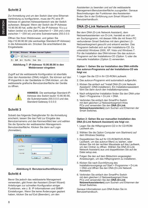
Öffnen Sie Ihren Webbrowser, und geben Sie http://10.90.90.90 (die werkseitige Standard-IP-Adresse) in die Adresszeile ein. Drücken Sie anschließend die Eingabetaste.
Abbildung 7: IP-Adresse 10.90.90.90 in den Webbrowser eingeben
Zugriff auf die webbasierte Konfiguration ist ebenfalls über den Assistenten (DNA) möglich. Sie können auf den IP-Hyperlink in der Geräteliste im DNA klicken, um die webbasierte grafische Benutzeroberfläche der Geräte zu öffnen.
HINWEIS: Die werkseitige Standard-IP-Adresse des Switch lautet 10.90.90.90, die Subnetzmaske 255.0.0.0 und das Standard-Gateway 0.0.0.0
Schritt 3Sobald das folgende Dialogfenster für die Anmeldung erscheint, lassen Sie das Feld zur Eingabe des Benutzernamens und das Kennwortfeld leer und wählen Sie die Sprache der webbasierten Management-Benutzeroberfläche. Klicken Sie dann auf Login (Anmelden).
Abbildung 8: Benutzerauthentifizierung
Schritt 4Bevor Sie jedoch das webbasierte Management verwenden, gibt Ihnen der Assistent (Smart Wizard) Anleitungen zur schnellen Konfiguration einiger Funktionen, wie z. B. IP-Informationen und SNMP-Einstellungen. Wenn Sie keine Änderungen geplant haben, klicken Sie auf Exit (Beenden), um den
Assistenten zu beenden und auf die webbasierte Management-Benutzeroberfläche zuzugreifen. Genaue Beschreibungen der Funktionen des Assistenten finden Sie in der Einführung zum Smart Wizard im Benutzerhandbuch.
DNA (D-Link Network Assistant)
Bei dem DNA (D-Link Network Assistant), dem Netzwerkassistenten von D-Link, handelt es sich um ein Suchprogramm, mit dessen Hilfe die mit Ihrem PC verbundenen Smart Switches mit dem gleichen L2-Netzwerksegment gesucht und erkannt werden. Das Programm befindet sich auf der Installations-CD. Es unterstützt Windows 2000, XP, Vista und Windows 7. Für die Installation des DNA können Sie das autorun-Programm auf der Installations-CD (Option 1) oder die manuelle Installation (Option 2) verwenden.
Option 1: Gehen Sie zur Installation des DNA mithilfe des autorun-Programms auf der Installations-CD wie folgt vor.1. Legen Sie die CD in Ihr CD-ROM-Laufwerk.2. Das autorun-Programm wird automatisch aufgerufen.3. Klicken Sie einfach auf ”Install DNA (D-Link Network
Assistant)” (DNA installieren). Ein Installationsassistent führt Sie dann durch den Installationsprozess.
4. Nach erfolgreicher Installation finden Sie den DNA unter Start > Programme > D-Link > DNA.
5. Verbinden Sie einfach den SmartPro Switch mit dem gleichen L2 Netzwerksegment Ihres PCs und verwenden Sie den DNA (D-Link Netzwerkassistenten) zum Suchen und Erkennen der Smart Switches.
Option 2: Gehen Sie zur manuellen Installation des DNA (D-Link Network Assistant) wie folgt vor.1. Legen Sie die Hilfsprogramm-CD in Ihr CD-ROM-
Laufwerk ein.2. Wählen Sie die Option Computer vom Startmenü auf
dem Windows Desktop.3. Doppelklicken Sie auf Ihr CD-ROM/DVD-ROM-
Laufwerk, um das autorun-Menü zu starten, oder klicken Sie mit der rechten Maustaste auf das Laufwerk, um den Ordner zu öffnen. Wählen Sie DNA (D-Link Network Assistant) aus und doppelklicken Sie auf die Datei setup.exe.
4. Folgen Sie den auf dem Bildschirm angezeigten Anweisungen, um das Hilfsprogramm zu installieren.
5. Klicken Sie nach Durchführung des Installationsvorgangs auf Start > Programme > D-Link > DNA und öffnen Sie den DNA (D-Link Network Assistant).
6. Verbinden Sie einfach den SmartPro Switch mit dem gleichen L2 Netzwerksegment Ihres PCs und verwenden Sie den DNA (D-Link Netzwerkassistenten) zum Suchen und Erkennen der Smart Switches.
Genaue Informationen zum DNA finden Sie im Benutzerhandbuch.
9
DE
UT
SC
H
Anschluss des Konsolenports
Zum Anschluss an den seriellen Port muss ein spezielles Konsolenkabel verwendet werden. Dieses Kabel ist im Lieferumfang dieses Produkts enthalten. Es wird hier als RS-232-to-RJ-45 Verbindungskabel bezeichnet, dessen spezielle Pinbelegung zum Anschluss an den seriellen Port dieses Switch unter Verwendung der korrekten Pinkonfiguration dient.
Gehen Sie wie folgt vor, um eine Verbindung zu dem Konsolenport des Switch herzustellen:
1. Schließen Sie das RS-232-Ende des Konsolenkabels an den seriellen Port des Management-PCs an.
2. Schließen Sie das RJ-45-Ende des Konsolenkabels an den Konsolenport des Switch an.
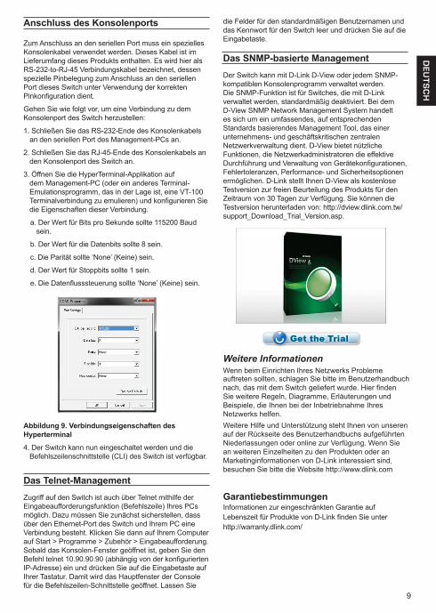
3. Öffnen Sie die HyperTerminal-Applikation auf dem Management-PC (oder ein anderes Terminal-Emulationsprogramm, das in der Lage ist, eine VT-100 Terminalverbindung zu emulieren) und konfigurieren Sie die Eigenschaften dieser Verbindung.
a. Der Wert für Bits pro Sekunde sollte 115200 Baud sein.
b. Der Wert für die Datenbits sollte 8 sein.
c. Die Parität sollte ‘None’ (Keine) sein.
d. Der Wert für Stoppbits sollte 1 sein.
e. Die Datenflusssteuerung sollte ‘None’ (Keine) sein.
Abbildung 9. Verbindungseigenschaften des Hyperterminal
4. Der Switch kann nun eingeschaltet werden und die Befehlszeilenschnittstelle (CLI) des Switch ist verfügbar.
Das Telnet-ManagementZugriff auf den Switch ist auch über Telnet mithilfe der Eingabeaufforderungsfunktion (Befehlszeile) Ihres PCs möglich. Dazu müssen Sie zunächst sicherstellen, dass über den Ethernet-Port des Switch und Ihrem PC eine Verbindung besteht. Klicken Sie dann auf Ihrem Computer auf Start > Programme > Zubehör > Eingabeaufforderung. Sobald das Konsolen-Fenster geöffnet ist, geben Sie den Befehl telnet 10.90.90.90 (abhängig von der konfigurierten IP-Adresse) ein und drücken Sie auf die Eingabetaste auf Ihrer Tastatur. Damit wird das Hauptfenster der Console für die Befehlszeilen-Schnittstelle geöffnet. Lassen Sie
die Felder für den standardmäßigen Benutzernamen und das Kennwort für den Switch leer und drücken Sie auf die Eingabetaste.
Das SNMP-basierte ManagementDer Switch kann mit D-Link D-View oder jedem SNMP-kompatiblen Konsolenprogramm verwaltet werden. Die SNMP-Funktion ist für Switches, die mit D-Link verwaltet werden, standardmäßig deaktiviert. Bei dem D-View SNMP Network Management System handelt es sich um ein umfassendes, auf entsprechenden Standards basierendes Management Tool, das einer unternehmens- und geschäftskritischen zentralen Netzwerkverwaltung dient. D-View bietet nützliche Funktionen, die Netzwerkadministratoren die effektive Durchführung und Verwaltung von Gerätekonfigurationen, Fehlertoleranzen, Performance- und Sicherheitsoptionen ermöglichen. D-Link stellt Ihnen D-View als kostenlose Testversion zur freien Beurteilung des Produkts für den Zeitraum von 30 Tagen zur Verfügung. Sie können die Testversion herunterladen von: http://dview.dlink.com.tw/support_Download_Trial_Version.asp.
Weitere InformationenWenn beim Einrichten Ihres Netzwerks Probleme auftreten sollten, schlagen Sie bitte im Benutzerhandbuch nach, das mit dem Switch geliefert wurde. Hier finden Sie weitere Regeln, Diagramme, Erläuterungen und Beispiele, die Ihnen bei der Inbetriebnahme Ihres Netzwerks helfen.Weitere Hilfe und Unterstützung steht Ihnen von unseren auf der Rückseite des Benutzerhandbuchs aufgeführten Niederlassungen oder online zur Verfügung. Wenn Sie an weiteren Einzelheiten zu den Produkten oder an Marketinginformationen von D-Link interessiert sind, besuchen Sie bitte die Website http://www.dlink.com
GarantiebestimmungenInformationen zur eingeschränkten Garantie aufLebenszeit für Produkte von D-Link finden Sie unterhttp://warranty.dlink.com/
10
FR
AN
ÇA
IS
À propos de ce guideCe guide contient des instructions détaillées concernant la configuration de tous les commutateurs SmartPro par D-Link, ainsi que les déclarations de garantie, sécurité, règlementaires et environnementales correspondantes. Notez que le modèle que vous avez acheté peut légèrement différer de celui illustré sur les figures. Pour obtenir des informations plus détaillées sur votre switch, ses composants, ses connexions réseau et ses spécifications techniques, reportez-vous au Guide de l’utilisateur fourni dans son emballage.
Étape 1 : déballageOuvrez le carton d’expédition et sortez-en le contenu avec précaution. Le Guide de l’utilisateur contient une liste des éléments devant se trouver dans l’emballage ; en vous y reportant, vérifiez que tous les composants sont présents et en parfait état. Si un élément est absent ou détérioré, contactez votre revendeur D-Link pour en obtenir un nouveau.- Un commutateur SmartPro D-Link
- Un support pour montage en armoire
- Pieds en caoutchouc
- Un cordon d’alimentation
- Un câble console
- Une attache pour cordon d’alimentation
- Le CD du Guide de l’utilisateur, incluant l’ DNA (D-Link Network Assistant)
- Un guide de démarrage multilingue
Étape 2 : installation du switchPour installer et utiliser le switch en toute sécurité, nous vous recommandons de procéder comme suit :• Inspectez le cordon d’alimentation et assurez-vous
qu’il est parfaitement relié au connecteur d’alimentation secteur.
• Vérifiez que le switch présente une dissipation de chaleur adaptée et qu’il est entouré d’un espace suffisant pour garantir une bonne ventilation.
• Ne posez pas d’objets lourds sur le switch.
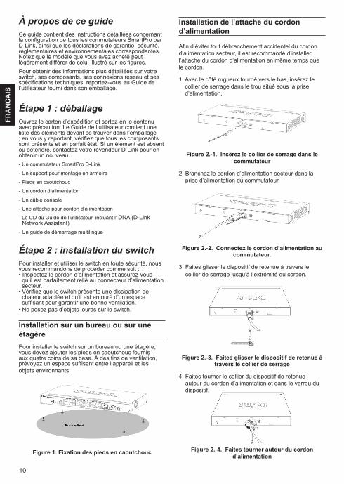
Installation sur un bureau ou sur une étagèrePour installer le switch sur un bureau ou une étagère, vous devez ajouter les pieds en caoutchouc fournis aux quatre coins de sa base. À des fins de ventilation, prévoyez un espace suffisant entre l’appareil et les objets environnants.
Figure 1. Fixation des pieds en caoutchouc
Installation de l’attache du cordon d’alimentation
Afin d’éviter tout débranchement accidentel du cordon d’alimentation secteur, il est recommandé d’installer l’attache du cordon d’alimentation en même temps que le cordon.
1. Avec le côté rugueux tourné vers le bas, insérez le collier de serrage dans le trou situé sous la prise d’alimentation.
Figure 2.-1. Insérez le collier de serrage dans le commutateur
2. Branchez le cordon d’alimentation secteur dans la prise d’alimentation du commutateur.
Figure 2.-2. Connectez le cordon d’alimentation au commutateur.
3. Faites glisser le dispositif de retenue à travers le collier de serrage jusqu’à l’extrémité du cordon.
Figure 2.-3. Faites glisser le dispositif de retenue à travers le collier de serrage
4. Faites tourner le collier du dispositif de retenue autour du cordon d’alimentation et dans le verrou du dispositif.
Figure 2.-4. Faites tourner autour du cordon d’alimentation
11
FR
AN
ÇA
IS
Panne de courantEn cas de panne de courant, par précaution, débranchez le switch. Rebranchez-le une fois le courant rétabli.
Options de gestionCe système peut être géré hors-bande via le port de console du panneau avant/arrière ou intrabande via Telnet. L’utilisateur peut aussi choisir l’interface de gestion Web, accessible par l’intermédiaire d’un navigateur Web. Chaque commutateur peut avoir sa propre adresse IP utilisée pour la communication avec un gestionnaire réseau SNMP ou toute autre application TCP/IP (par exemple, BOOTP, TFTP, etc.). L’adresse par défaut du commutateur est 10.90.90.90. Vous pouvez modifier l’adresse IP par défaut du commutateur en fonction du schéma d’adressage de votre réseau.
Interface de gestion WebUne fois l’installation physique effectuée, vous pouvez configurer le switch, surveiller les voyants et afficher des graphiques de statistiques à l’aide d’un navigateur Web (Netscape Navigator version 6.2 ou supérieure, ou Microsoft® Internet Explorer version 5.0 ou supérieure, par exemple).
Pour commencer la configuration Web de votre unité, vous avez besoin des éléments suivants :
• PC équipé d’une connexion Ethernet RJ-45
• Câble Ethernet standard
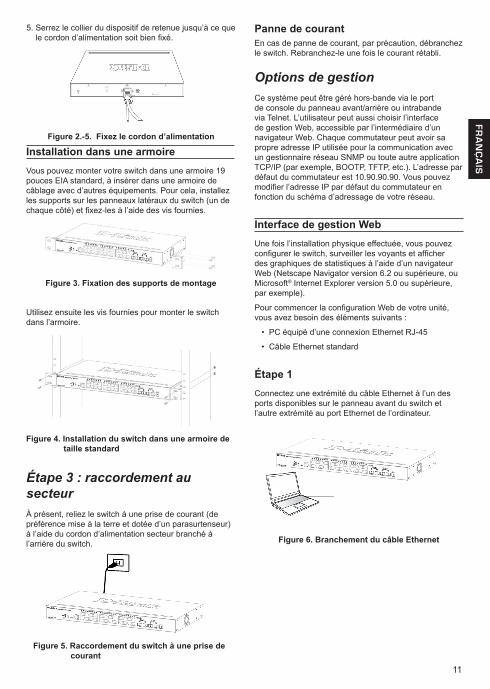
Étape 1Connectez une extrémité du câble Ethernet à l’un des ports disponibles sur le panneau avant du switch et l’autre extrémité au port Ethernet de l’ordinateur.
Figure 6. Branchement du câble Ethernet
Installation dans une armoire Vous pouvez monter votre switch dans une armoire 19 pouces EIA standard, à insérer dans une armoire de câblage avec d’autres équipements. Pour cela, installez les supports sur les panneaux latéraux du switch (un de chaque côté) et fixez-les à l’aide des vis fournies.
Figure 3. Fixation des supports de montage
Utilisez ensuite les vis fournies pour monter le switch dans l’armoire.
Figure 4. Installation du switch dans une armoire de taille standard
Étape 3 : raccordement au secteurÀ présent, reliez le switch à une prise de courant (de préférence mise à la terre et dotée d’un parasurtenseur) à l’aide du cordon d’alimentation secteur branché à l’arrière du switch.
Figure 5. Raccordement du switch à une prise de courant
5. Serrez le collier du dispositif de retenue jusqu’à ce que le cordon d’alimentation soit bien fixé.
Figure 2.-5. Fixez le cordon d’alimentation
12
FR
AN
ÇA
IS
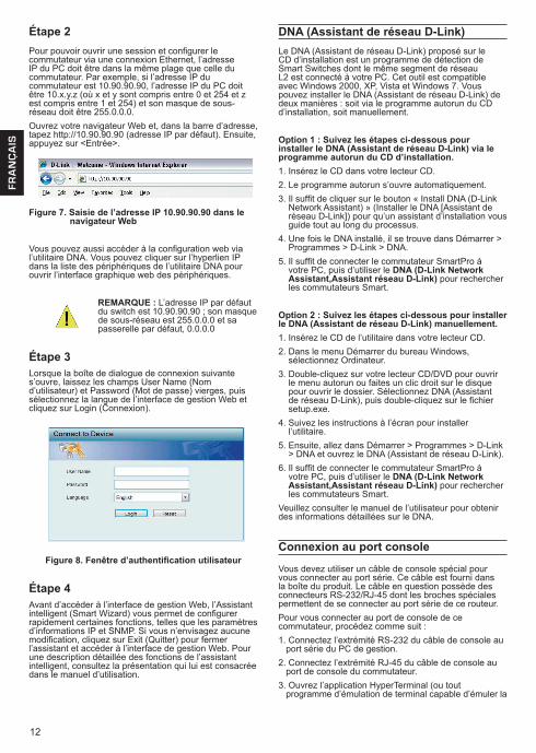
Étape 2Pour pouvoir ouvrir une session et configurer le commutateur via une connexion Ethernet, l’adresse IP du PC doit être dans la même plage que celle du commutateur. Par exemple, si l’adresse IP du commutateur est 10.90.90.90, l’adresse IP du PC doit être 10.x.y.z (où x et y sont compris entre 0 et 254 et z est compris entre 1 et 254) et son masque de sous-réseau doit être 255.0.0.0.Ouvrez votre navigateur Web et, dans la barre d’adresse, tapez http://10.90.90.90 (adresse IP par défaut). Ensuite, appuyez sur <Entrée>.
Figure 7. Saisie de l’adresse IP 10.90.90.90 dans le navigateur Web
Vous pouvez aussi accéder à la configuration web via l’utilitaire DNA. Vous pouvez cliquer sur l’hyperlien IP dans la liste des périphériques de l’utilitaire DNA pour ouvrir l’interface graphique web des périphériques.
REMARQUE : L’adresse IP par défaut du switch est 10.90.90.90 ; son masque de sous-réseau est 255.0.0.0 et sa passerelle par défaut, 0.0.0.0
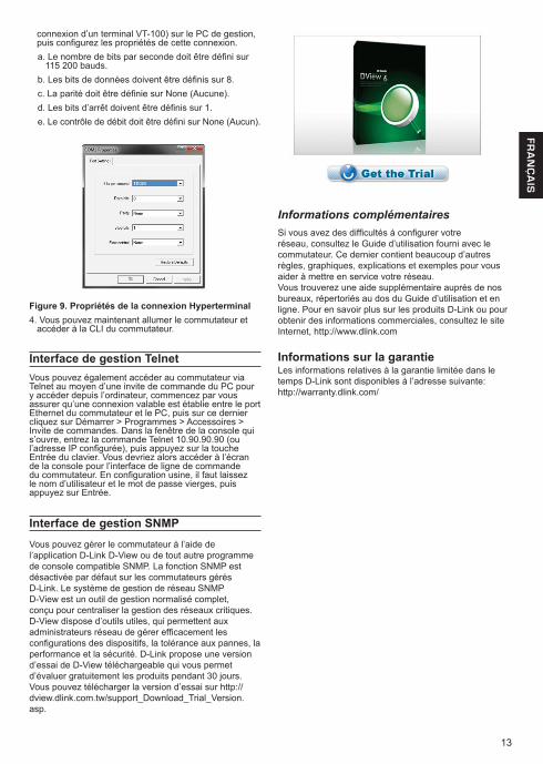
Étape 3Lorsque la boîte de dialogue de connexion suivante s’ouvre, laissez les champs User Name (Nom d’utilisateur) et Password (Mot de passe) vierges, puis sélectionnez la langue de l’interface de gestion Web et cliquez sur Login (Connexion).
Figure 8. Fenêtre d’authentification utilisateur
Étape 4Avant d’accéder à l’interface de gestion Web, l’Assistant intelligent (Smart Wizard) vous permet de configurer rapidement certaines fonctions, telles que les paramètres d’informations IP et SNMP. Si vous n’envisagez aucune modification, cliquez sur Exit (Quitter) pour fermer l’assistant et accéder à l’interface de gestion Web. Pour une description détaillée des fonctions de l’assistant intelligent, consultez la présentation qui lui est consacrée dans le manuel d’utilisation.
DNA (Assistant de réseau D-Link)Le DNA (Assistant de réseau D-Link) proposé sur le CD d’installation est un programme de détection de Smart Switches dont le même segment de réseau L2 est connecté à votre PC. Cet outil est compatible avec Windows 2000, XP, Vista et Windows 7. Vous pouvez installer le DNA (Assistant de réseau D-Link) de deux manières : soit via le programme autorun du CD d’installation, soit manuellement.
Option 1 : Suivez les étapes ci-dessous pour installer le DNA (Assistant de réseau D-Link) via le programme autorun du CD d’installation.1. Insérez le CD dans votre lecteur CD.2. Le programme autorun s’ouvre automatiquement.3. Il suffit de cliquer sur le bouton « Install DNA (D-Link
Network Assistant) » (Installer le DNA [Assistant de réseau D-Link]) pour qu’un assistant d’installation vous guide tout au long du processus.
4. Une fois le DNA installé, il se trouve dans Démarrer > Programmes > D-Link > DNA.
5. Il suffit de connecter le commutateur SmartPro à votre PC, puis d’utiliser le DNA (D-Link Network Assistant,Assistant réseau D-Link) pour rechercher les commutateurs Smart.
Option 2 : Suivez les étapes ci-dessous pour installer le DNA (Assistant de réseau D-Link) manuellement.1. Insérez le CD de l’utilitaire dans votre lecteur CD.2. Dans le menu Démarrer du bureau Windows,
sélectionnez Ordinateur.3. Double-cliquez sur votre lecteur CD/DVD pour ouvrir
le menu autorun ou faites un clic droit sur le disque pour ouvrir le dossier. Sélectionnez DNA (Assistant de réseau D-Link), puis double-cliquez sur le fichier setup.exe.
4. Suivez les instructions à l’écran pour installer l’utilitaire.
5. Ensuite, allez dans Démarrer > Programmes > D-Link > DNA et ouvrez le DNA (Assistant de réseau D-Link).
6. Il suffit de connecter le commutateur SmartPro à votre PC, puis d’utiliser le DNA (D-Link Network Assistant,Assistant réseau D-Link) pour rechercher les commutateurs Smart.
Veuillez consulter le manuel de l’utilisateur pour obtenir des informations détaillées sur le DNA.
Connexion au port console Vous devez utiliser un câble de console spécial pour vous connecter au port série. Ce câble est fourni dans la boîte du produit. Le câble en question possède des connecteurs RS-232/RJ-45 dont les broches spéciales permettent de se connecter au port série de ce routeur.Pour vous connecter au port de console de ce commutateur, procédez comme suit :1. Connectez l’extrémité RS-232 du câble de console au
port série du PC de gestion.2. Connectez l’extrémité RJ-45 du câble de console au
port de console du commutateur.3. Ouvrez l’application HyperTerminal (ou tout
programme d’émulation de terminal capable d’émuler la
13
FR
AN
ÇA
IS
connexion d’un terminal VT-100) sur le PC de gestion, puis configurez les propriétés de cette connexion.a. Le nombre de bits par seconde doit être défini sur
115 200 bauds.b. Les bits de données doivent être définis sur 8. c. La parité doit être définie sur None (Aucune). d. Les bits d’arrêt doivent être définis sur 1. e. Le contrôle de débit doit être défini sur None (Aucun).
Figure 9. Propriétés de la connexion Hyperterminal4. Vous pouvez maintenant allumer le commutateur et
accéder à la CLI du commutateur.
Interface de gestion TelnetVous pouvez également accéder au commutateur via Telnet au moyen d’une invite de commande du PC pour y accéder depuis l’ordinateur, commencez par vous assurer qu’une connexion valable est établie entre le port Ethernet du commutateur et le PC, puis sur ce dernier cliquez sur Démarrer > Programmes > Accessoires > Invite de commandes. Dans la fenêtre de la console qui s’ouvre, entrez la commande Telnet 10.90.90.90 (ou l’adresse IP configurée), puis appuyez sur la touche Entrée du clavier. Vous devriez alors accéder à l’écran de la console pour l’interface de ligne de commande du commutateur. En configuration usine, il faut laissez le nom d’utilisateur et le mot de passe vierges, puis appuyez sur Entrée.
Interface de gestion SNMPVous pouvez gérer le commutateur à l’aide de l’application D-Link D-View ou de tout autre programme de console compatible SNMP. La fonction SNMP est désactivée par défaut sur les commutateurs gérés D-Link. Le système de gestion de réseau SNMP D-View est un outil de gestion normalisé complet, conçu pour centraliser la gestion des réseaux critiques. D-View dispose d’outils utiles, qui permettent aux administrateurs réseau de gérer efficacement les configurations des dispositifs, la tolérance aux pannes, la performance et la sécurité. D-Link propose une version d’essai de D-View téléchargeable qui vous permet d’évaluer gratuitement les produits pendant 30 jours. Vous pouvez télécharger la version d’essai sur http://dview.dlink.com.tw/support_Download_Trial_Version.asp.
Informations complémentairesSi vous avez des difficultés à configurer votre réseau, consultez le Guide d’utilisation fourni avec le commutateur. Ce dernier contient beaucoup d’autres règles, graphiques, explications et exemples pour vous aider à mettre en service votre réseau.Vous trouverez une aide supplémentaire auprès de nos bureaux, répertoriés au dos du Guide d’utilisation et en ligne. Pour en savoir plus sur les produits D-Link ou pour obtenir des informations commerciales, consultez le site Internet, http://www.dlink.com
Informations sur la garantieLes informations relatives à la garantie limitée dans le temps D-Link sont disponibles à l’adresse suivante: http://warranty.dlink.com/
14
ES
PA
ÑO
L
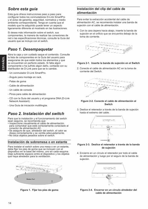
Sobre esta guíaEsta guía ofrece instrucciones paso a paso para configurar todos los conmutadores D-Link SmartPro y el aviso de garantía, seguridad, normativa y medio ambiente correspondiente. Tenga en cuenta que el modelo que ha adquirido puede tener un aspecto ligeramente diferente al mostrado en las ilustraciones.
Si desea más información sobre el switch, sus componentes, la manera de realizar las conexiones de red o las especificaciones técnicas, consulte la Guía del usuario que se incluye con el switch.
Paso 1. DesempaquetarAbra la caja y con cuidado saque el contenido. Consulte la lista de componentes en la Guía del usuario para asegurarse de que están todos los elementos y que se encuentran en perfecto estado. Si falta algún componente o ha sufrido algún daño, contacte con su distribuidor de D-Link para que se lo cambie.
- Un conmutador D-Link SmartPro.
- Ángulo para montaje en rack.
- Patas de goma
- Cable de alimentación
- Un cable de consola
- Pinza para cable de alimentación
- CD con la Guía del usuario y el programa DNA (D-Link Network Assistant).
- Una Guía de iniciación multilingüe.
Paso 2. Instalación del switchPara que la instalación y el funcionamiento del switch sean seguros, se recomienda que:• Inspeccione visualmente el cable de alimentación
para comprobar que está correctamente conectado al conector de alimentación AC.
• Se asegure de que, alrededor del switch, el calor se disipa correctamente y se ventila adecuadamente.
• No sitúa objetos pesados sobre el switch.
Instalación de sobremesa o en estantePara instalar el switch sobre una mesa o en un estante, debe fijar los pies de goma que se incluyen con el dispositivo en la base del mismo, uno en cada esquina. Deje suficiente espacio entre el dispositivo y los objetos que haya alrededor para la ventilación.
Figura 1. Fijar los pies de goma
Instalación del clip del cable de alimentación
Para evitar la extracción accidental del cable de alimentación AC, se recomienda instalar una banda de sujeción con el cable de alimentación.
1. Con la cara áspera hacia abajo, inserte la banda de sujeción en el orificio que se encuentra debajo de la toma de corriente.
Figura 2-1. Inserte la banda de sujeción en el Switch
2. Conecte el cable de alimentación AC en la toma de corriente del Switch.
Figure 2-2. Conecte el cable de alimentación al Switch
3. Deslice el retenedor a través de la banda de sujeción hasta el extremo del cable.
Figura 2-3. Deslice el retenedor a través de la banda de sujeción
4. Encierre en un círculo el retenedor por todo el cable de alimentación y luego por el seguro de la banda de sujeción.
Figura 2-4. Encerrar en un círculo alrededor del cable de alimentación
15
ES
PA
ÑO
L
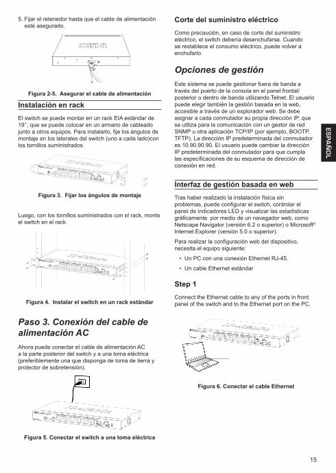
Corte del suministro eléctricoComo precaución, en caso de corte del suministro eléctrico, el switch debería desenchufarse. Cuando se restablece el consumo eléctrico, puede volver a enchufarlo.
Opciones de gestiónEste sistema se puede gestionar fuera de banda a través del puerto de la consola en el panel frontal/posterior o dentro de banda utilizando Telnet. El usuario puede elegir también la gestión basada en la web, accesible a través de un explorador web. Se debe asignar a cada conmutador su propia dirección IP, que se utiliza para la comunicación con un gestor de red SNMP u otra aplicación TCP/IP (por ejemplo, BOOTP, TFTP). La dirección IP predeterminada del conmutador es 10.90.90.90. El usuario puede cambiar la dirección IP predeterminada del conmutador para que cumpla las especificaciones de su esquema de dirección de conexión en red.
Interfaz de gestión basada en webTras haber realizado la instalación física sin problemas, puede configurar el switch, controlar el panel de indicadores LED y visualizar las estadísticas gráficamente por medio de un navegador web, como Netscape Navigator (versión 6.2 o superior) o Microsoft®
Internet Explorer (versión 5.0 o superior).
Para realizar la configuración web del dispositivo, necesita el equipo siguiente:
• Un PC con una conexión Ethernet RJ-45.
• Un cable Ethernet estándar
Step 1Connect the Ethernet cable to any of the ports in front panel of the switch and to the Ethernet port on the PC.
Figura 6. Conectar el cable Ethernet
Instalación en rackEl switch se puede montar en un rack EIA estándar de 19’’, que se puede colocar en un armario de cableado junto a otros equipos. Para instalarlo, fije los ángulos de montaje en los laterales del switch (uno a cada lado)con los tornillos suministrados.
Figura 3. Fijar los ángulos de montaje
Luego, con los tornillos suministrados con el rack, monte el switch en el rack.
Figura 4. Instalar el switch en un rack estándar
Paso 3. Conexión del cable de alimentación ACAhora puede conectar el cable de alimentación AC a la parte posterior del switch y a una toma eléctrica (preferiblemente una que disponga de toma de tierra y protector de sobretensión).
Figura 5. Conectar el switch a una toma eléctrica
5. Fijar el retenedor hasta que el cable de alimentación esté asegurado.
Figura 2-5. Asegurar el cable de alimentación
16
ES
PA
ÑO
L
Paso 2Para iniciar sesión y configurar el switch a través de una conexión Ethernet, el PC debe tener una dirección IP en el mismo rango que el switch. Por ejemplo, si el switch tiene una dirección IP de 10.90.90.90, el PC debe tener una dirección IP de 10.x.y.z (donde x/y es un número entre 0 y 254 y z es un número entre 1 y 254), y una máscara de subred de 255.0.0.0.Abra el navegador web y escriba http://10.90.90.90 (la dirección IP por defecto) en el campo de direcciones. Luego pulse <Intro>.
Figura 7. Introducir la dirección IP 10.90.90.90 en el navegador web
También se puede acceder a la configuración web a través del DNA. Puede hacer clic en el hipervínculo de la lista de dispositivos en el DNA para abrir la GUI web de los dispositivos.
NOTA: La dirección IP por defecto del switch es 10.90.90.90, con una máscara de subred de 255.0.0.0 y un gateway por defecto de 0.0.0.0
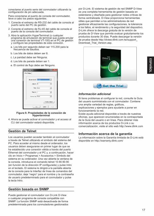
Paso 3Cuando aparezca el cuadro de diálogo de inicio de sesión, deje en blanco el nombre de usuario y la contraseña, elija el idioma de la interfaz de gestión basada en la web y, a continuación, haga clic en Inicio de sesión.
Figura 8. Ventana de autentificación del usuario
Paso 4Antes de acceder a la gestión basada en web, el Asistente inteligente le guiará para configurar rápidamente algunos funciones, como Información de IP y Parámetros de SNMP. Si no tiene previsto cambiar nada, haga clic en Salir para salir del asistente y entrar en la gestión basada en la web. Para ver detalladamente las funciones del Asistente inteligente, consulte la introducción al Asistente inteligente en el manual de usuario.
DNA (Asistente para red D-Link)
El DNA (Asistente para red D-Link) incluido en el CD de instalación es un programa para detectar conmutadores inteligentes con el mismo segmento de red L2 conectado al PC. Esta herramienta es compatible con Windows 2000, XP, Vista y Windows 7. Existen dos opciones para la instalación del DNA (Asistente para red D-Link), una a través del programa de ejecución automática del CD de instalación y otra mediante la instalación manual.
Opción 1: Siga estos pasos para instalar el DNA (Asistente para red D-Link) a través del programa de ejecución automática del CD de instalación.
1. Introduzca el CD en la unidad de CD-ROM.
2. El programa de ejecución automática se abrirá automáticamente
3. Simplemente haga clic en el botón ”Instalar DNA (Asistente para red D-Link)” y un asistente de instalación le guiará a través del proceso.
4. Tras instalar correctamente el DNA, podrá encontrarlo dentro de Inicio > Programas > D-Link > DNA.
5. Solo tiene que conectar el conmutador SmartPro en el mismo segmento de red L2 del PC y utilizar el DNA (Asistente para red D-Link) para detectar los conmutadores inteligentes.
Opción 2: Siga estos pasos para instalar el DNA (Asistente para red D-Link) de forma manual.
1. Inserte el CD de utilidades en la unidad de CD-ROM.
2. Desde el menú Inicio en el escritorio de Windows, seleccione Mi PC.
3. Haga doble clic en la unidad de CD-ROM/DVD-ROM para iniciar el menú de ejecución automática o haga clic con el botón derecho del ratón en la unidad para abrir la carpeta. Seleccione DNA (Asistente para red D-Link) y haga doble clic en el archivo setup.exe.
4. Siga las instrucciones que aparecen en pantalla para instalar la utilidad.
5. Después de finalizar, vaya a Inicio > Programas > D-Link > DNA y abra el DNA (Asistente para red D-Link).
6. Solo tiene que conectar el conmutador SmartPro en el mismo segmento de red L2 del PC y utilizar el DNA (Asistente para red D-Link) para detectar los conmutadores inteligentes.
Para obtener información detallada sobre el DNA, consulte el manual de usuario.
Conexión del puerto de la consolaPara conectarlo al puerto serie, se debe utilizar un cable de consola especial. Este cable se incluye en el paquete del producto. El cable denominado cable conector de RS-232 a RJ-45 cuenta con las patillas específicas para
17
ES
PA
ÑO
L
conectarse al puerto serie del conmutador utilizando la configuración de pin adecuada.Para conectarse al puerto de consola del conmutador, lleve a cabo los pasos siguientes:1. Conecte el extremo de RS-232 del cable de consola al
puerto serie del PC de gestión.2. Conecte el extremo de RJ-45 del cable de consola al
puerto de la consola del conmutador.3. Abra la aplicación HyperTerminal (o cualquier
programa de emulación de terminal que pueda emular una conexión de terminal VT-100) en el PC de gestión y configure las propiedades de esta conexión.a. Los bits por segundo deben ser 115.200 para la
frecuencia de baudios.b. Los bits de datos deben ser 8. c. La paridad debe ser Ninguna. d. Los bits de parada deben ser 1. e. El control de flujo debe ser Ninguno.
Figura 9. Propiedades de la conexión de Hyperterminal
4. Ahora se puede activar el conmutador y el acceso al CLI del conmutador estará disponible.
Gestión de TelnetLos usuarios pueden acceder también al conmutador a través de Telnet utilizando el símbolo del sistema del PC. Para acceder al mismo desde el ordenador, los usuarios deben asegurarse en primer lugar de que se ha establecido una conexión válida a través del puerto Ethernet del conmutador y el PC y, a continuación, hacer clic en Inicio > Programas > Accesorios > Símbolo del sistema en su ordenador. Una vez abierta la ventana de la consola, introduzca el comando telnet 10.90.90.90 (en función de la dirección IP configurada) y pulse Intro en el teclado. El sistema le dirigirá a la pantalla abierta de la consola para la Interfaz de línea de comandos del conmutador, deje “negro” para el nombre y la contraseña de usuario predeterminado para el conmutador y pulse la tecla Intro.
Gestión basada en SNMPPuede gestionar el conmutador con D-Link D-View o cualquier programa de consola compatible con SNMP. La función SNMP está desactivada de forma predeterminada para los conmutadores gestionados
por D-Link. El sistema de gestión de red SNMP D-View es una completa herramienta de gestión basada en estándares y diseñada para gestionar redes críticas de forma centralizada. D-View proporciona herramientas útiles que permiten a los administradores de red gestionar eficazmente las configuraciones, la tolerancia a los fallos, el rendimiento y la seguridad del dispositivo. D-Link ofrece la descarga gratuita de la versión de prueba de D-View que permite evaluar gratuitamente los productos durante 30 días. Puede descargar la versión de prueba desde http://dview.dlink.com.tw/support_Download_Trial_Version.asp.
Información adicionalSi tiene problemas al configurar la red, consulte la Guía del usuario suministrada con el conmutador. Contiene una amplia variedad de reglas, gráficos,explicaciones y ejemplos para ayudarle a poner en funcionamiento la red.Existe ayuda adicional disponible a través de nuestras oficinas, que aparecen enumeradas en la contraportada de la Guía del usuario o en línea. Para obtener más información acerca de los productos D-Link o su comercialización, visite el sitio web http://www.dlink.com
Información acerca de la garantía La información sobre la Garantía limitada de D-Link está disponible en http://warranty.dlink.com/
18
ITA
LIA
NO
Informazioni sul presente manualeLa presente guida contiene istruzioni passo-passo per la configurazione di tutti gli switch D-Link SmartPro oltre alle informazioni su garanzia, sicurezza, conformità alle normative e avvisi sulla salvaguardia dell’ambiente. Notare che il modello acquistato potrebbe essere leggermente diverso da quello raffigurato nelle illustrazioni. Maggiori informazioni sullo switch, i suoi componenti, le connessioni di rete e le specifiche tecniche sono contenute nel Manuale utente fornito con il prodotto.
Fase 1 – DisimballaggioAprire la confezione ed estrarne delicatamente il contenuto. Verificare il contenuto del pacchetto, confrontandolo con l’elenco riportato nel manuale utente. Se un componente dovesse risultare mancante o danneggiato, contattare il rivenditore D-Link locale per la sostituzione.- Uno switch D-Link SmartPro - Staffe per montaggio su rack- Piedini in gomma- Cavo di alimentazione- Un cavo di connessione alla console- Clip per cavo di alimentazione- CD del Manuale utente con programma DNA (D-Link
Network Assistant)- 1 manuale rapido di installazione multilingue
Fase 2 – Installazione dello switchPer una installazione sicura dello switch, si consiglia di:• Ispezionare il cavo di alimentazione e verificare che sia
correttamente fissato al relativo connettore CA.• Verificare che attorno allo switch ci sia lo spazio
sufficiente per un’adeguata ventilazione e dissipazione del calore.
• Non posizionare oggetti pesanti sopra lo switch.
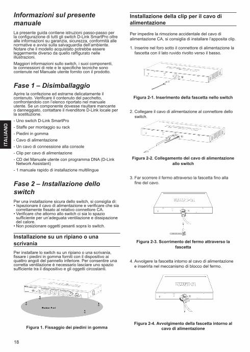
Installazione su un ripiano o una scrivaniaPer installare lo switch su un ripiano o una scrivania, fissare i piedini in gomma forniti con il dispositivo ai quattro angoli del pannello inferiore. Per consentire una corretta ventilazione è necessario lasciare uno spazio sufficiente tra il dispositivo e gli oggetti circostanti.
Figura 1. Fissaggio dei piedini in gomma
Installazione della clip per il cavo di alimentazione
Per impedire la rimozione accidentale del cavo di alimentazione CA, si consiglia di installare l’apposita clip.
1. Inserire nel foro sotto il connettore di alimentazione la fascetta con il lato ruvido rivolto verso il basso.
Figura 2-1. Inserimento della fascetta nello switch
2. Collegare il cavo di alimentazione al connettore dello switch.
Figura 2-2. Collegamento del cavo di alimentazione allo switch
3. Far scorrere il fermo attraverso la fascetta fino alla fine del cavo.
Figura 2-3. Scorrimento del fermo attraverso la fascetta
4. Avvolgere la fascetta intorno al cavo di alimentazione e inserirla nel meccanismo di blocco del fermo.
Figura 2-4. Avvolgimento della fascetta intorno al cavo di alimentazione
19
ITALIA
NO
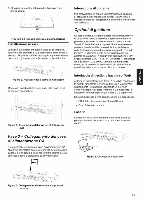
Installazione su rackLo switch può essere montato in un rack da 19 pollici, conforme allo standard EIA, posizionabile in un armadio elettrico. Fissare le staffe di montaggio ai pannelli laterali dello switch (una per lato) e fermarle con le viti fornite.
Figura 3. Fissaggio delle staffe di montaggio
Montare lo switch all’interno del rack, utilizzando le viti fornite con quest’ultimo.
Figura 4. Installazione dello switch all’interno del rack
Fase 3 – Collegamento del cavo di alimentazione CAÈ ora possibile connettere il cavo di alimentazione CA al relativo connettore posto sul pannello posteriore dello switch e a una presa di corrente (preferibilmente dotata di messa a terra e protezione da sovratensioni).
Figura 5. Collegamento dello switch alla presa di corrente
5. Stringere la fascetta del fermo finché il cavo non risulta fissato.
Figura 2-5. Fissaggio del cavo di alimentazione
Interruzione di correntePer precauzione, in caso di un’interruzione di corrente si consiglia di disconnettere lo switch. Riconnettere il dispositivo quando l’erogazione di corrente elettrica torna alla normalità.
Opzioni di gestioneQuesto sistema può essere gestito fuori banda, tramite la porta della console presente sul pannello anteriore/posteriore, oppure con connessione in banda tramite Telnet. L’utente ha inoltre la possibilità di scegliere una gestione basata su Web accessibile tramite browser web. A ciascuno switch deve avere assegnato il proprio indirizzo IP, utilizzato per la comunicazione con un gestore di rete SNMP o con un’altra applicazione TCP/IP (per esempio BOOTP; TFTP). L’indirizzo IP predefinito dello switch è 10.90.90.90. L’utente può modificare l’indirizzo IP predefinito dello switch per soddisfare le specifiche del proprio schema di indirizzi di rete.
Interfaccia di gestione basata sul WebAl termine dell’installazione fisica, è possibile configurare lo switch, monitorare il pannello dei LED e visualizzare graficamente le statistiche utilizzando un browser come Netscape Navigator (versione 6.2 o superiore) o Microsoft® Internet Explorer (versione 5.0 o superiore).
Requisiti necessari per la configurazione del dispositivo:
• PC dotato di connessione Ethernet RJ-45
• Cavo Ethernet standard
Fase 1:Collegare il cavo Ethernet a una delle porte poste sul pannello frontale dello switch e a una porta Ethernet del PC.
Figura 6. Connessione del cavo
20
ITA
LIA
NO
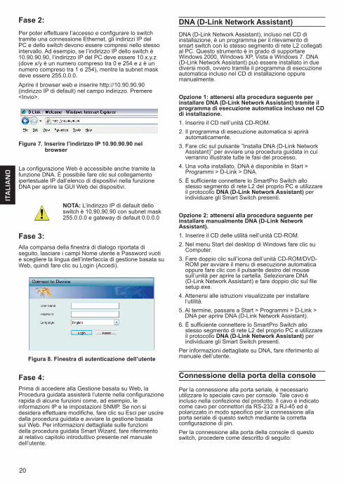
Fase 2:Per poter effettuare l’accesso e configurare lo switch tramite una connessione Ethernet, gli indirizzi IP del PC e dello switch devono essere compresi nello stesso intervallo. Ad esempio, se l’indirizzo IP dello switch è 10.90.90.90, l’indirizzo IP del PC deve essere 10.x.y.z (dove x/y è un numero compreso tra 0 e 254 e z è un numero compreso tra 1 e 254), mentre la subnet mask deve essere 255.0.0.0.Aprire il browser web e inserire http://10.90.90.90 (indirizzo IP di default) nel campo indirizzo. Premere <Invio>.
Figure 7. Inserire l’indirizzo IP 10.90.90.90 nel browser
La configurazione Web è accessibile anche tramite la funzione DNA. È possibile fare clic sul collegamento ipertestuale IP dall’elenco di dispositivi nella funzione DNA per aprire la GUI Web dei dispositivi.
NOTA: L’indirizzo IP di default dello switch è 10.90.90.90 con subnet mask 255.0.0.0 e gateway di default 0.0.0.0
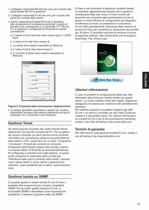
Fase 3:Alla comparsa della finestra di dialogo riportata di seguito, lasciare i campi Nome utente e Password vuoti e scegliere la lingua dell’interfaccia di gestione basata su Web, quindi fare clic su Login (Accedi).
Figura 8. Finestra di autenticazione dell’utente
Fase 4:Prima di accedere alla Gestione basata su Web, la Procedura guidata assisterà l’utente nella configurazione rapida di alcune funzioni come, ad esempio, le informazioni IP e le impostazioni SNMP. Se non si desidera effettuare modifiche, fare clic su Esci per uscire dalla procedura guidata e avviare la gestione basata sul Web. Per informazioni dettagliate sulle funzioni della procedura guidata Smart Wizard, fare riferimento al relativo capitolo introduttivo presente nel manuale dell’utente.
DNA (D-Link Network Assistant)DNA (D-Link Network Assistant), incluso nel CD di installazione, è un programma per il rilevamento di smart switch con lo stesso segmento di rete L2 collegati al PC. Questo strumento è in grado di supportare Windows 2000, Windows XP, Vista e Windows 7. DNA (D-Link Network Assistant) può essere installato in due diversi modi, ovvero tramite il programma di esecuzione automatica incluso nel CD di installazione oppure manualmente.
Opzione 1: attenersi alla procedura seguente per installare DNA (D-Link Network Assistant) tramite il programma di esecuzione automatica incluso nel CD di installazione.1. Inserire il CD nell’unità CD-ROM.2. Il programma di esecuzione automatica si aprirà
automaticamente.3. Fare clic sul pulsante ”Installa DNA (D-Link Network
Assistant)” per avviare una procedura guidata in cui verranno illustrate tutte le fasi del processo.
4. Una volta installato, DNA è disponibile in Start > Programmi > D-Link > DNA.
5. È sufficiente connettere lo SmartPro Switch allo stesso segmento di rete L2 del proprio PC e utilizzare il protocollo DNA (D-Link Network Assistant) per individuare gli Smart Switch presenti.
Opzione 2: attenersi alla procedura seguente per installare manualmente DNA (D-Link Network Assistant).1. Inserire il CD delle utilità nell’unità CD-ROM.2. Nel menu Start del desktop di Windows fare clic su
Computer.3. Fare doppio clic sull’icona dell’unità CD-ROM/DVD-
ROM per avviare il menu di esecuzione automatica oppure fare clic con il pulsante destro del mouse sull’unità per aprire la cartella. Selezionare DNA (D-Link Network Assistant) e fare doppio clic sul file setup.exe.
4. Attenersi alle istruzioni visualizzate per installare l’utilità.
5. Al termine, passare a Start > Programmi > D-Link > DNA per aprire DNA (D-Link Network Assistant).
6. È sufficiente connettere lo SmartPro Switch allo stesso segmento di rete L2 del proprio PC e utilizzare il protocollo DNA (D-Link Network Assistant) per individuare gli Smart Switch presenti.
Per informazioni dettagliate su DNA, fare riferimento al manuale dell’utente.
Connessione della porta della console
Per la connessione alla porta seriale, è necessario utilizzare lo speciale cavo per console. Tale cavo è incluso nella confezione del prodotto. Il cavo è indicato come cavo per connettori da RS-232 a RJ-45 ed è polarizzato in modo specifico per la connessione alla porta seriale di questo switch mediante la corretta configurazione di pin.Per la connessione alla porta della console di questo switch, procedere come descritto di seguito:
21
ITALIA
NO
1. Collegare l’estremità RS-232 del cavo per console alla porta seriale del PC di gestione.
2. Collegare l’estremità RJ-45 del cavo per console alla porta per console dello switch.
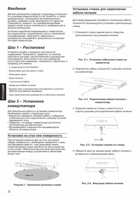
3. Aprire l’applicazione HyperTerminal (o qualsiasi altro programma di emulazione terminali in grado di emulare una connessione a un terminale VT-100) sul PC di gestione e configurare le Proprietà di questa connessione.a. Il valore di bit al secondo deve essere pari a 115200
baud.b. Il valore di bit dati deve essere 8. c. La parità deve essere impostata su Nessuna. d. Il valore di bit di stop deve essere 1. e. Il controllo di flusso deve essere impostato su
Nessuno.
Figura 9. Proprietà della connessione Hyperterminal4. È adesso possibile accendere lo switch per rendere
disponibile l’accesso alla relativa Interfaccia da riga di comando (CLI, Command Line Interface).
Gestione TelnetGli utenti possono accedere allo switch tramite Telnet utilizzando il prompt dei comandi del PC. Per accedervi dal proprio computer, gli utenti devono prima verificare che esista una connessione valida tra la porta Ethernet dello switch e il PC, quindi fare clic su Start > Programmi > Accessori > Prompt dei comandi sul computer. All’apertura della finestra relativa alla console, inserire il comando telnet 10.90.90.90 (a seconda dell’indirizzo IP configurato) e premere Invio sulla tastiera. A questo punto comparirà la schermata della console per l’Interfaccia della riga di comando dello switch. Lasciare vuoti i campi relativi a nome utente e password per utilizzare i valori predefiniti per lo switch, quindi premere Invio.
Gestione basata su SNMPÈ possibile gestire lo switch tramite D-Link D-View o qualsiasi altro programma per console compatibile SNMP. Per gli switch gestiti mediante D-Link, la funzionalità SNMP è disabilitata come impostazione predefinita. Il sistema di gestione delle reti SNMP
D-View è uno strumento di gestione completo basato su standard, appositamente pensato per la gestione centralizzata della rete critica. D-View include utili strumenti per consentire agli amministratori di rete di gestire in modo efficace le configurazioni dei dispositivi, la tolleranza di errore, le prestazioni e la sicurezza. D-Link offre gratuitamente il download della versione di prova di D-View per consentire la valutazione dei prodotti per 30 giorni. È possibile scaricare la versione di prova al seguente indirizzo: http://dview.dlink.com.tw/support_Download_Trial_Version.asp.
Ulteriori informazioniIn caso di problemi di configurazione della rete, fare riferimento alla Guida per l’utente fornita con questo switch. La Guida contiene molte altre regole, diagrammi, spiegazioni ed esempi per rendere la rete perfettamente operativa.Per ulteriore supporto è possibile rivolgersi agli uffici D-Link il cui elenco è riportato nel retro della Guida per l’utente o è disponibile online. Per ulteriori informazioni sui prodotti D-Link o per la documentazione marketing, visitare il sito Web all’indirizzo http://www.dlink.com
Termini di garanziaPer informazioni sulla garanzia limitata D-Link, visitare ilsito all’indirizzo http://warranty.dlink.com/
22
PYC
CКИ
Й
ВведениеДанное руководство содержит пошаговые инструкции по установке коммутаторов D-Link SmartPro, а также документацию, касающуюся эксплуатационных условий, правовых норм, безопасности и гарантии. Пожалуйста, помните, что приобретенная Вами модель может слегка отличаться от изображенной в данном руководстве. За более подробной информацией о коммутаторе, его компонентах, подключении к сети и технической спецификацией, пожалуйста, обратитесь к руководству пользователя, включенного в комплект поставки коммутатора.
Шаг 1 – РаспаковкаОткройте коробку и аккуратно достаньте ее содержимое. Пожалуйста, сверьтесь со списком комплекта поставки, расположенным в руководстве пользователя. Если какой-то из этих элементов отсутствует или поврежден, пожалуйста, обратитесь к продавцу для замены.- 1 коммутатор D-Link SmartPro
- Кронштейны для монтажа в стойку
- Резиновые ножки
- Шнур питания
- 1 консольный кабель
- Зажим для кабеля питания
- Компакт-диск с руководством пользователя и утилитой DNA (D-Link Network Assistant)
- Одно мультиязычное руководство по быстрой установке
Шаг 2 – Установка коммутатораДля безопасной работы и установки коммутатора необходимо сделать следующие шаги:• Визуально проверьте силовой кабель и убедитесь
в безопасности его подключения к разъему питания переменного тока
• Убедитесь, что вокруг коммутатора достаточно пространства для вентиляции
• Не размещайте тяжелые или нагревающиеся объекты на коммутаторе
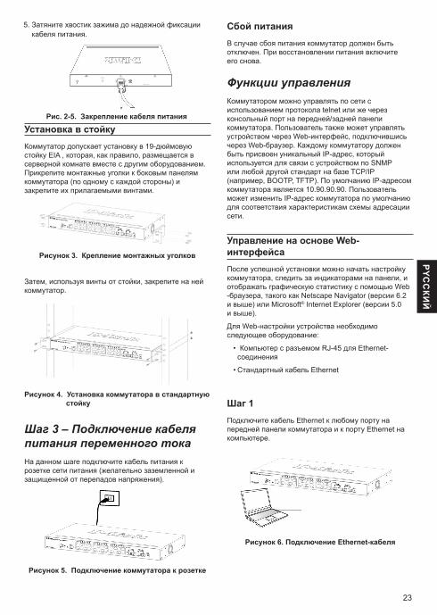
Установка на стол или поверхностьПри установке коммутатора на стол или какую-нибудь поверхность, необходимо прикрепить к нему поставляемые вместе с ним резиновые ножки. Самоклеющиеся ножки крепятся на дне устройства по его углам. Обеспечьте достаточное пространство для вентиляции между устройством и объектами вокруг него.
Рисунок 1. Крепление резиновых ножек
Установка стяжки для закрепления кабеля питания
Для предотвращения случайного отключения кабеля питания AC рекомендуется установить фиксирующую стяжку.
1. Установите стяжку замком вниз в отверстие, расположенное под разъемом питания.
Рис. 2-1. Установка кабельной стяжки на коммутатор
2. Подключите кабель питания AC к разъему питания на коммутаторе.
Рис. 2-2. Подключение кабеля питания к коммутатору
3. Наденьте зажим на стяжку и сместите его в сторону разъема для подключения кабеля питания.
Рис. 2-3. Установка зажима на стяжку
4. Оберните хвостик зажима вокруг кабеля питания и вставьте его в фиксирующий замок..
Рис. 2-4. Фиксация кабеля питания
23
PYC
CКИ
Й
Установка в стойкуКоммутатор допускает установку в 19-дюймовую стойку EIA , которая, как правило, размещается в серверной комнате вместе с другим оборудованием. Прикрепите монтажные уголки к боковым панелям коммутатора (по одному с каждой стороны) и закрепите их прилагаемыми винтами.
Рисунок 3. Крепление монтажных уголков
Затем, используя винты от стойки, закрепите на ней коммутатор.
Рисунок 4. Установка коммутатора в стандартную стойку
Шаг 3 – Подключение кабеля питания переменного токаНа данном шаге подключите кабель питания к розетке сети питания (желательно заземленной и защищенной от перепадов напряжения).
Рисунок 5. Подключение коммутатора к розетке
5. Затяните хвостик зажима до надежной фиксации кабеля питания.
Рис. 2-5. Закрепление кабеля питания
Сбой питанияВ случае сбоя питания коммутатор должен быть отключен. При восстановлении питания включите его снова.
Функции управленияКоммутатором можно управлять по сети с использованием протокола telnet или же через консольный порт на передней/задней панели коммутатора. Пользователь также может управлять устройством через Web-интерфейс, подключившись через Web-браузер. Каждому коммутатору должен быть присвоен уникальный IP-адрес, который используется для связи с устройством по SNMP или любой другой стандарт на базе TCP/IP (например, BOOTP, TFTP). По умолчанию IP-адресом коммутатора является 10.90.90.90. Пользователь может изменить IP-адрес коммутатора по умолчанию для соответствия характеристикам схемы адресации сети.
Управление на основе Web-интерфейсаПосле успешной установки можно начать настройку коммутатора, следить за индикаторами на панели, и отображать графическую статистику с помощью Web -браузера, такого как Netscape Navigator (версии 6.2 и выше) или Microsoft® Internet Explorer (версии 5.0 и выше).
Для Web-настройки устройства необходимо следующее оборудование:
• Компьютер с разъемом RJ-45 для Ethernet-соединения
• Стандартный кабель Ethernet
Шаг 1Подключите кабель Ethernet к любому порту на передней панели коммутатора и к порту Ethernet на компьютере.
Рисунок 6. Подключение Ethernet-кабеля
24
PYC
CКИ
Й
Шаг 2
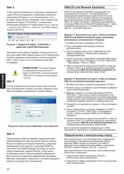
Чтобы зарегистрироваться и настроить коммутатор через Ethernet-соединение, необходимо назначить компьютеру IP-адрес из того же диапазона, что и IP-адрес коммутатора. Например, если коммутатору присвоен IP-адрес 10.90.90.90, то компьютеру необходимо присвоить IP-адрес вида 10.x.y.z (где x/y – числа от 0 до 254, а z – число от 1 до 254) и маску подсети 255.0.0.0.
Рисунок 7. Введите IP-адрес 10.90.90.90 в адресной строке Web-браузера
Настройка через Web-интерфейс также может быть доступна через DNA. Можно нажать на IP-гиперссылку соответствующего коммутатора в списке устройств DNA, чтобы открыть его пользовательский Web-интерфейс.
ПРИМЕЧАНИЕ: На коммутаторах по умолчанию используется IP-адрес 10.90.90.90 с маской подсети - 255.0.0.0 и шлюзом по умолчанию - 0.0.0.0
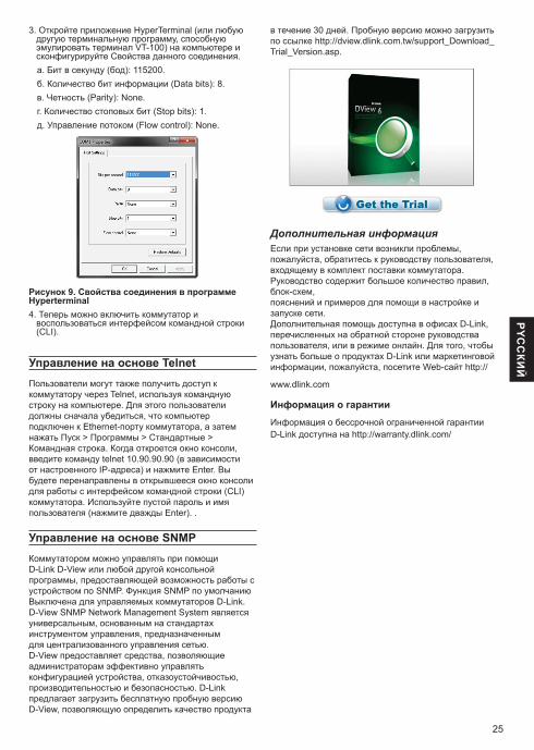
Шаг 3После появления диалогового окна входа оставьте имя пользователя и пароль пустыми, выберите язык Web-интерфейса управления и нажмите Войти.
Рисунок 8. Окно аутентификации пользователя
Шаг 4Перед входом в Web-интерфейс управления (Web-based Management), Мастер (Smart Wizard) поможет быстро настроить некоторые параметры, например, информацию об IP-адресе и настройки SNMP (Ip Information and SNMP Settings). Если Вы не хотите делать изменений, нажмите Выход, чтобы выйти из Мастера и войти в Web-интерфейс управления. Для получения подробной информации о функциях Мастера, пожалуйста, обратитесь к соответствующему разделу в руководстве пользователя.
DNA (D-Link Network Assistant)DNA (D-Link Network Assistant), находящийся на установочном CD-диске, - это программа для обнаружения коммутаторов серии Smart в том же L2 сегменте сети, в котором находится компьютер. Данный инструмент может поддерживать Windows 2000, XP, Vista и Windows 7. Возможны два варианта установки DNA (D-Link Network Assistant): один – через программу автозапуска с установочного CD-диска, другой – установка вручную.
Вариант 1: Выполните эти шаги, чтобы установить DNA (D-Link Network Assistant) через программу автозапуска с установочного CD-диска.1. Вставьте CD-диск в дисковод CD-Rom.2. Окно программы автозапуска появится
автоматически.3. Просто нажмите на кнопке ”Install DNA (D-Link
Network Assistant)” и выполните установку с помощью Мастера.
4. После успешного завершения установки DNA можно будет найти в Start > Programs > D-Link > DNA (Пуск > Программы > D-Link > DNA).
5. Просто подключите коммутатор SmartPro к тому же сегменту сети L2, в котором находится компьютер, и используйте DNA (D-Link Network Assistant) для обнаружения коммутаторов серии Smart.
Вариант 2: Выполните эти шаги, чтобы установить DNA (D-Link Network Assistant) вручную.1. Вставьте CD-диск с утилитой в дисковод CD-Rom.2. В меню «Пуск» на рабочем столе Windows выберите
пункт «Мой Компьютер».3. Дважды нажмите на значке дисковода CD-Rom/
DVD-Rom, чтобы открыть меню автозапуска, или нажмите правой кнопкой мыши на значке дисковода, чтобы открыть папку. Выберите DNA (D-Link Network Assistant) и дважды нажмите на файле setup.exe.
4. Следуйте инструкциям на экране, чтобы установить утилиту.
5. После завершения установки перейдите в Start > Programs > D-Link > DNA (Пуск > Программы > D-Link > DNA) и откройте DNA (D-Link Network Assistant).
6. Просто подключите коммутатор SmartPro к тому же сегменту сети L2, в котором находится компьютер, и используйте DNA (D-Link Network Assistant) для обнаружения коммутаторов серии Smart.
Для получения подробной информации о DNA, пожалуйста, обратитесь к руководству пользователя.
Подключение к консольному портуДля подключения к консольному порту необходимо использовать специальный консольный кабель. Данный кабель входит в комплект поставки и именуется как соединительный кабель с разъемом RS-232 с одной стороны и RJ-45 – с другой.Для подключения к консольному порту коммутатора выполните следующее:1. Подключите кабель разъемом RS-232 к
консольному порту компьютера.2. Подключите кабель разъемом RJ-45 к консольному
порту коммутатора.
25
PYC
CКИ
Й3. Откройте приложение HyperTerminal (или любую
другую терминальную программу, способную эмулировать терминал VT-100) на компьютере и сконфигурируйте Свойства данного соединения.а. Бит в секунду (бод): 115200. б. Количество бит информации (Data bits): 8.в. Четность (Parity): None.г. Количество стоповых бит (Stop bits): 1.д. Управление потоком (Flow control): None.
Рисунок 9. Свойства соединения в программе Hyperterminal4. Теперь можно включить коммутатор и
воспользоваться интерфейсом командной строки (CLI).
Управление на основе TelnetПользователи могут также получить доступ к коммутатору через Telnet, используя командную строку на компьютере. Для этого пользователи должны сначала убедиться, что компьютер подключен к Ethernet-порту коммутатора, а затем нажать Пуск > Программы > Стандартные > Командная строка. Когда откроется окно консоли, введите команду telnet 10.90.90.90 (в зависимости от настроенного IP-адреса) и нажмите Enter. Вы будете перенаправлены в открывшееся окно консоли для работы с интерфейсом командной строки (CLI) коммутатора. Используйте пустой пароль и имя пользователя (нажмите дважды Enter). .
Управление на основе SNMPКоммутатором можно управлять при помощи D-Link D-View или любой другой консольной программы, предоставляющей возможность работы c устройством по SNMP. Функция SNMP по умолчанию Выключена для управляемых коммутаторов D-Link. D-View SNMP Network Management System является универсальным, основанным на стандартах инструментом управления, предназначенным для централизованного управления сетью. D-View предоставляет средства, позволяющие администраторам эффективно управлять конфигурацией устройства, отказоустойчивостью, производительностью и безопасностью. D-Link предлагает загрузить бесплатную пробную версию D-View, позволяющую определить качество продукта
в течение 30 дней. Пробную версию можно загрузить по ссылке http://dview.dlink.com.tw/support_Download_Trial_Version.asp.
Дополнительная информацияЕсли при установке сети возникли проблемы, пожалуйста, обратитесь к руководству пользователя, входящему в комплект поставки коммутатора. Руководство содержит большое количество правил, блок-схем,пояснений и примеров для помощи в настройке и запуске сети.Дополнительная помощь доступна в офисах D-Link, перечисленных на обратной стороне руководства пользователя, или в режиме онлайн. Для того, чтобы узнать больше о продуктах D-Link или маркетинговой информации, пожалуйста, посетите Web-сайт http://
www.dlink.com
Информация о гарантии
Информация о бессрочной ограниченной гарантииD-Link доступна на http://warranty.dlink.com/
26
PO
RT
UG
UÊ
S
Sobre esse GuiaEste guia fornece instruções passo -a-passo para configurar os switches D -Link Metro Ethernet e para a Garantia, segurança, regulamentares e Meio Ambiente . Por favor, note que o modelo que você comprou podem se paresentar diferentes daqueles mostrados nas ilustrações.
Para informações mais detalhadas sobre o seu switch, seus componentes, estabelecimento das conexões de rede e especificações técnicas, favor consultar o Guia do Usuário incluído com o seu switch.
Etapa 1 – DesembalandoAbra a embalagem e desembale cuidadosamente o seu conteúdo. Favor consultar o conteúdo da embalagem localizado no Guia do Usuário para certificar-se de que todos os itens estejam presentes e intactos. Se qualquer item estiver faltando ou danificado, favor contatar seu revendedor local D-Link para realizar a reposição.- Um Switch D-Link SmartPro - Braçadeira para montagem em rack- Pés de borracha- Cabo de alimentação- Um cabo de console- Um cabo de energia- CD contendo o Guia do Usuário com o programa DNA
(D-Link Network Assistant)- Um Guia Rápido multilíngüe
Etapa 2 – Instalação do SwitchPara uma instalação e operação seguras do switch, é recomendável que você:• Inspecione visualmente o cabo de alimentação para se
certificar-se de que o mesmo esteja totalmente preso ao conector de alimentação CA
• Certifique que há dissipação de calor e ventilação adequadas em torno do switch
• Não coloque objetos pesados sob o switch
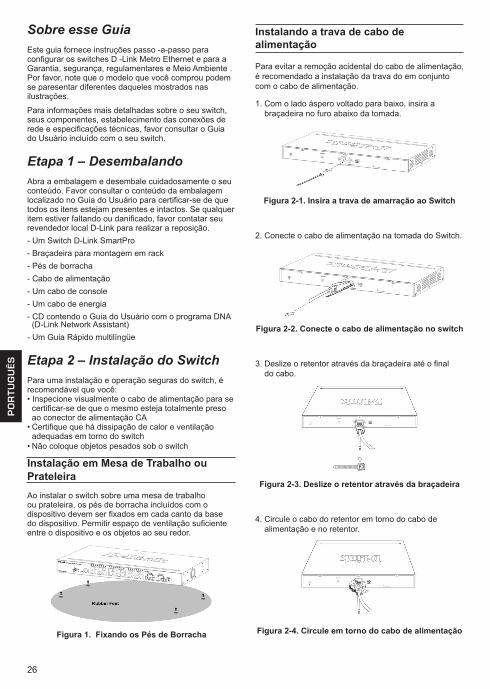
Instalação em Mesa de Trabalho ou PrateleiraAo instalar o switch sobre uma mesa de trabalho ou prateleira, os pés de borracha incluídos com o dispositivo devem ser fixados em cada canto da base do dispositivo. Permitir espaço de ventilação suficiente entre o dispositivo e os objetos ao seu redor.
Figura 1. Fixando os Pés de Borracha
Instalando a trava de cabo de alimentação
Para evitar a remoção acidental do cabo de alimentação, é recomendado a instalação da trava do em conjunto com o cabo de alimentação.
1. Com o lado áspero voltado para baixo, insira a braçadeira no furo abaixo da tomada.
Figura 2-1. Insira a trava de amarração ao Switch
2. Conecte o cabo de alimentação na tomada do Switch.
Figura 2-2. Conecte o cabo de alimentação no switch
3. Deslize o retentor através da braçadeira até o final do cabo.
Figura 2-3. Deslize o retentor através da braçadeira
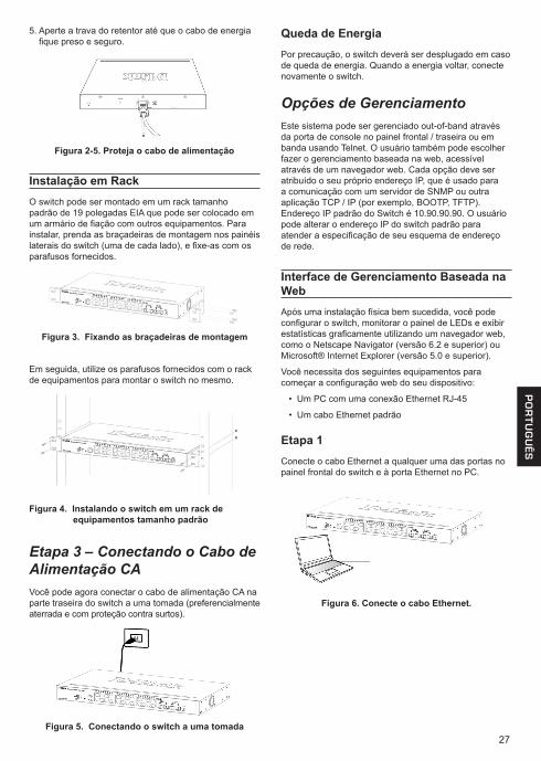
4. Circule o cabo do retentor em torno do cabo de alimentação e no retentor.
Figura 2-4. Circule em torno do cabo de alimentação
27
PO
RT
UG
UÊ
S
Instalação em RackO switch pode ser montado em um rack tamanho padrão de 19 polegadas EIA que pode ser colocado em um armário de fiação com outros equipamentos. Para instalar, prenda as braçadeiras de montagem nos painéis laterais do switch (uma de cada lado), e fixe-as com os parafusos fornecidos.
Figura 3. Fixando as braçadeiras de montagem
Em seguida, utilize os parafusos fornecidos com o rack de equipamentos para montar o switch no mesmo.
Figura 4. Instalando o switch em um rack de equipamentos tamanho padrão
Etapa 3 – Conectando o Cabo de Alimentação CAVocê pode agora conectar o cabo de alimentação CA na parte traseira do switch a uma tomada (preferencialmente aterrada e com proteção contra surtos).
Figura 5. Conectando o switch a uma tomada
5. Aperte a trava do retentor até que o cabo de energia fique preso e seguro.
Figura 2-5. Proteja o cabo de alimentação
Queda de EnergiaPor precaução, o switch deverá ser desplugado em caso de queda de energia. Quando a energia voltar, conecte novamente o switch.
Opções de GerenciamentoEste sistema pode ser gerenciado out-of-band através da porta de console no painel frontal / traseira ou em banda usando Telnet. O usuário também pode escolher fazer o gerenciamento baseada na web, acessível através de um navegador web. Cada opção deve ser atribuído o seu próprio endereço IP, que é usado para a comunicação com um servidor de SNMP ou outra aplicação TCP / IP (por exemplo, BOOTP, TFTP). Endereço IP padrão do Switch é 10.90.90.90. O usuário pode alterar o endereço IP do switch padrão para atender a especificação de seu esquema de endereço de rede.
Interface de Gerenciamento Baseada na WebApós uma instalação física bem sucedida, você pode configurar o switch, monitorar o painel de LEDs e exibir estatísticas graficamente utilizando um navegador web, como o Netscape Navigator (versão 6.2 e superior) ou Microsoft® Internet Explorer (versão 5.0 e superior).
Você necessita dos seguintes equipamentos para começar a configuração web do seu dispositivo:
• Um PC com uma conexão Ethernet RJ-45
• Um cabo Ethernet padrão
Etapa 1Conecte o cabo Ethernet a qualquer uma das portas no painel frontal do switch e à porta Ethernet no PC.
Figura 6. Conecte o cabo Ethernet.
28
PO
RT
UG
UÊ
S
Etapa 2Para acessar e configurar o switch via uma conexão Ethernet, o PC deve ter um endereço IP no mesmo alcance do switch. Por exemplo, se o switch tem o endereço IP 10.90.90.90, o PC deveria ter o endereço IP 10.x.y.z (onde x/y é um número entre 0 ~ 254 e z um número entre 1 ~ 254) e a máscara de subrede 255.0.0.0.
Abra o seu navegador web e digite http://10.90.90.90 (o endereço IP padrão de fábrica) na caixa de endereços. Em seguida, pressione <Enter>.
Figura 7. Digite o endereço IP 10.90.90.90 no navegador web.
A configuração web também pode ser acessada através do DNA. Você pode clicar no link IP na lista de dispositivos no DNA para abrir a interface web de dispositivos.
OBSERVAÇÃO: O endereço IP padrão de fábrica do switch é 10.90.90.90 com uma máscara de sub-rede 255.0.0.0 e gateway padrão 0.0.0.0
Etapa 3Quando a caixa de diálogo de logon aparece, deixe tanto nome de usuário e a senha em branco e escolha o idioma da interface de gerenciamento, em seguida, clique em Login.
Antes de entrar na interface de gerenciamento Web, o Smart Wizard irá guiá-lo para configurar rapidamente algumas funções, tais como informações de IP e configurações de SNMP. Se você não pretende mudar nada, clique em Sair para sair do assistente e acesse a interface Web. Para informações detalhadas sobre as funções do Smart Wizard, consulte o manual do usuário.
Figura 8. Janela de autenticação do usuário.
Etapa 4Antes de entrar no Gerenciamento Baseado na Web, o Smart Wizard vai guiá-lo para configurar rapidamente
algumas funções, tais como Configurações de Senha, Configurações de SNMP, e Configurações de Sistema. Se você não planeja mudar nada, clique em Exit para sair do Assistente e entrar no de Gerenciamento Baseado na Web. Para uma análise detalhada das funções do Smart Wizard, favor consultar a introdução ao Smart Wizard no Manual do Usuário.
DNA (D-Link Network Assistant)O DNA (Assistente de rede D-Link), incluído no CD de instalação é um programa para descobrir Smart Switches no mesmo segmento de rede L2 conectado ao seu PC. Esta ferramenta pode suportar o Windows 2000, XP, Vista e Windows 7. Existem duas opções para a instalação do DNA, uma é através do programa de autorun no CD de instalação e a outro é a instalação manual.
Opção 1: Siga estes passos para instalar o DNA (Assistente de rede D-Link), através do programa de autorun no CD de instalação.1. Insira o CD na unidade de CD-ROM.
2. O programa de execução automática irá aparecer automaticamente
3. Basta clicar no botão “DNA Install (D-Link Network Assistant) e um assistente de instalação irá guiá-lo através do processo.
4. Depois de instalar com sucesso o DNA, você pode encontrá-lo em Iniciar> Programas> D-Link> DNA.
5. Basta ligar o Switch SmartPro para no mesmo segmento de rede L2 do seu PC e usar o DNA (Assistente de rede D-Link) para descobrir as Smart Switches.
Opção 2: Siga estes passos para instalar o DNA (D-Link Network Assistant) manualmente.1. Insira o CD de Utilitários no seu CD-ROM.
2. A partir do menu Iniciar no desktop do Windows, selecione Computador.
3. Dê um duplo clique no seu drive CD-ROM/DVD-ROM para iniciar o menu do autorun, ou clique direito sobre a unidade para abrir a pasta. Select (D-Link Network Assistant) e clique duas vezes no arquivo setup.exe.
4. Siga as instruções na tela para instalar o utilitário.
5. Após a conclusão, vá em Iniciar> Programas> D-Link> DNA e abra o (D-Link Network Assistant)
6. Basta ligar oSwitch SmartPro para no mesmo segmento de rede L2 do seu PC e usar o DNA (Assistente de rede D-Link) para descobrir as Smart Switches.
Para obter informações detalhadas sobre o DNA, por favor consulte o manual do usuário.
Conectando via porta de consolePara se conectar à porta serial, usar um cabo Console especial. Este cabo está incluso na embalagem do produto. O cabo com o conector RS-232 para cabo RJ-45 especificamente fixada para se conectar a porta serial deste switch usando a configuração correta de pin .
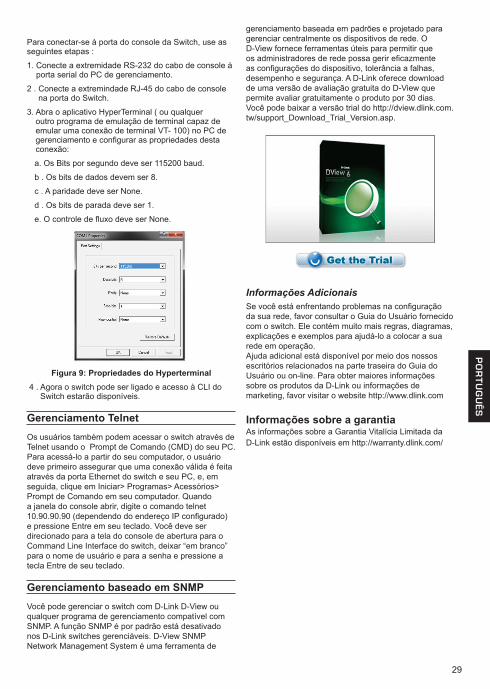
29
PO
RT
UG
UÊ
S
Para conectar-se à porta do console da Switch, use as seguintes etapas :
1. Conecte a extremidade RS-232 do cabo de console à porta serial do PC de gerenciamento.
2 . Conecte a extremindade RJ-45 do cabo de console na porta do Switch.
3. Abra o aplicativo HyperTerminal ( ou qualquer outro programa de emulação de terminal capaz de emular uma conexão de terminal VT- 100) no PC de gerenciamento e configurar as propriedades desta conexão:
a. Os Bits por segundo deve ser 115200 baud.
b . Os bits de dados devem ser 8.
c . A paridade deve ser None.
d . Os bits de parada deve ser 1.
e. O controle de fluxo deve ser None.
Figura 9: Propriedades do Hyperterminal 4 . Agora o switch pode ser ligado e acesso à CLI do
Switch estarão disponíveis.
Gerenciamento TelnetOs usuários também podem acessar o switch através de Telnet usando o Prompt de Comando (CMD) do seu PC. Para acessá-lo a partir do seu computador, o usuário deve primeiro assegurar que uma conexão válida é feita através da porta Ethernet do switch e seu PC, e, em seguida, clique em Iniciar> Programas> Acessórios> Prompt de Comando em seu computador. Quando a janela do console abrir, digite o comando telnet 10.90.90.90 (dependendo do endereço IP configurado) e pressione Entre em seu teclado. Você deve ser direcionado para a tela do console de abertura para o Command Line Interface do switch, deixar “em branco” para o nome de usuário e para a senha e pressione a tecla Entre de seu teclado.
Gerenciamento baseado em SNMPVocê pode gerenciar o switch com D-Link D-View ou qualquer programa de gerenciamento compatível com SNMP. A função SNMP é por padrão está desativado nos D-Link switches gerenciáveis. D-View SNMP Network Management System é uma ferramenta de
gerenciamento baseada em padrões e projetado para gerenciar centralmente os dispositivos de rede. O D-View fornece ferramentas úteis para permitir que os administradores de rede possa gerir eficazmente as configurações do dispositivo, tolerância a falhas, desempenho e segurança. A D-Link oferece download de uma versão de avaliação gratuita do D-View que permite avaliar gratuitamente o produto por 30 dias. Você pode baixar a versão trial do http://dview.dlink.com.tw/support_Download_Trial_Version.asp.
Informações AdicionaisSe você está enfrentando problemas na configuração da sua rede, favor consultar o Guia do Usuário fornecido com o switch. Ele contém muito mais regras, diagramas, explicações e exemplos para ajudá-lo a colocar a sua rede em operação.Ajuda adicional está disponível por meio dos nossos escritórios relacionados na parte traseira do Guia do Usuário ou on-line. Para obter maiores informações sobre os produtos da D-Link ou informações de marketing, favor visitar o website http://www.dlink.com
Informações sobre a garantiaAs informações sobre a Garantia Vitalícia Limitada daD-Link estão disponíveis em http://warranty.dlink.com/
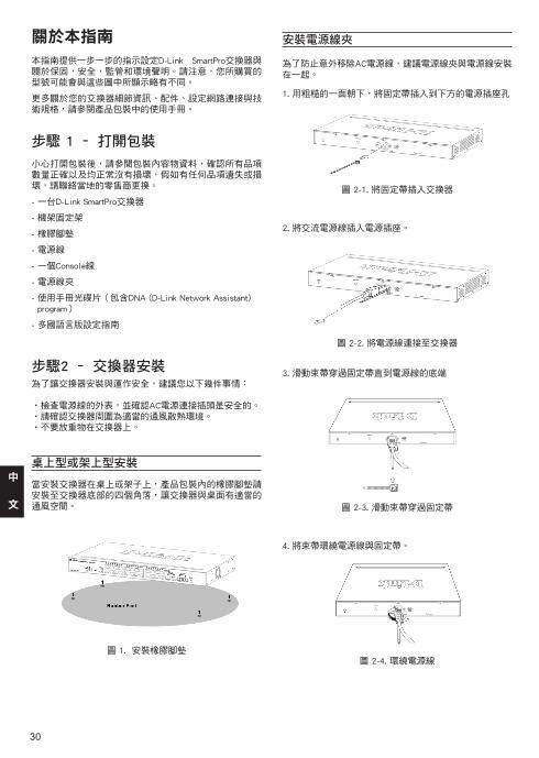
30
中
文
關於本指南
本指南提供一步一步的指示設定D-Link SmartPro交換器與關於保固,安全,監管和環境聲明。請注意,您所購買的型號可能會與這些圖中所顯示略有不同。
更多關於您的交換器細節資訊、配件、設定網路連接與技術規格,請參閱產品包裝中的使用手冊。
步驟 1 – 打開包裝
小心打開包裝後,請參閱包裝內容物資料,確認所有品項數量正確以及均正常沒有損壞,假如有任何品項遺失或損壞,請聯絡當地的零售商更換。
- 一台D-Link SmartPro交換器
- 機架固定架
- 橡膠腳墊
- 電源線
- 一個Console線
- 電源線夾
- 使用手冊光碟片(包含DNA (D-Link Network Assistant) program)
- 多國語言版設定指南
步驟2 – 交換器安裝為了讓交換器安裝與運作安全,建議您以下幾件事情:
•檢查電源線的外表,並確認AC電源連接插頭是安全的。•請確認交換器周圍為適當的通風散熱環境。•不要放重物在交換器上。
桌上型或架上型安裝
當安裝交換器在桌上或架子上,產品包裝內的橡膠腳墊請安裝至交換器底部的四個角落,讓交換器與桌面有適當的通風空間。
圖 1. 安裝橡膠腳墊
安裝電源線夾
為了防止意外移除AC電源線,建議電源線夾與電源線安裝在一起。
1. 用粗糙的一面朝下,將固定帶插入到下方的電源插座孔
圖 2-1. 將固定帶插入交換器
2. 將交流電源線插入電源插座。
圖 2-2. 將電源線連接至交換器
3. 滑動束帶穿過固定帶直到電源線的底端
圖 2-3. 滑動束帶穿過固定帶
4. 將束帶環繞電源線與固定帶。
圖 2-4. 環繞電源線
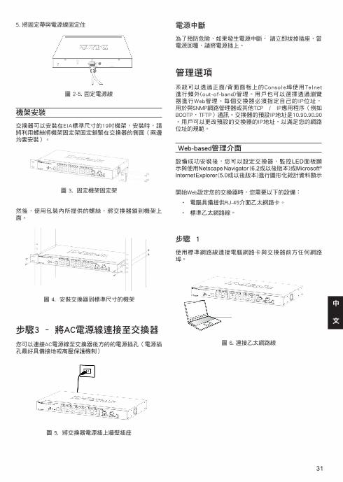
31
中
文
電源中斷
為了預防危險,如果發生電源中斷, 請立即拔掉插座,當電源回覆,請將電源插上。
管理選項
系統可以透過正面/背面面板上的Console埠使用Telnet進行頻外(out-of-band)管理。用戶也可以選擇透過瀏覽器進行Web管理。每個交換器必須指定自己的IP位址,用於與SNMP網路管理器或其他TCP / IP應用程序(例如BOOTP,TFTP)通訊。交換器的預設IP地址是10.90.90.90。用戶可以更改預設的交換器的IP地址,以滿足您的網路位址的規範。
Web-based管理介面
設備成功安裝後,您可以設定交換器、監控LED面板顯 示與使用Netscape Navigator (6.2或以後版本)或Microsoft® Internet Explorer (5.0或以後版本)進行圖形化統計資料顯示
開始Web設定您的交換器時,您需要以下的設備:
• 電腦具備提供RJ-45介面乙太網路卡。
• 標準乙太網路線。
步驟 1
使用標準網路線連接電腦網路卡與交換器前方任何網路埠。
圖 6. 連接乙太網路線
機架安裝
交換器可以安裝在EIA標準尺寸的19吋機架,安裝時,請將利用螺絲將機架固定架固定鎖緊在交換器的側面(兩邊均要安裝)。
圖 3. 固定機架固定架
然後,使用包裝內所提供的螺絲,將交換器鎖到機架上面。
圖 4. 安裝交換器到標準尺寸的機架
步驟3 – 將AC電源線連接至交換器
您可以連接AC電源線至交換器後方的的電源插孔(電源插孔最好具備接地或高壓保護機制)
圖 5. 將交換器電源插上牆壁插座
5. 將固定帶與電源線固定住
圖 2-5. 固定電源線
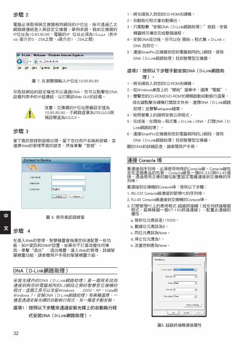
32
中
文
步驟 2
電腦必須取得與交換器相同網段的IP位址,始可透過乙太網路線連結登入與設定交換器,舉例來說,假如交換器的IP位址為10.90.90.90,電腦的IP 位址必須為10.x.y.z (其中 x/y 需介於0 ~ 254之間,z需介於1 ~ 254之間)
圖 7. 在瀏覽器輸入IP位址10.90.90.90
存取該網站的設定檔也可以通過DNA。您可以點擊在DNA設備列表中的IP超連結,以打開該Web GUI的設備。
注意:交換器的IP位址原廠設定值為10.90.90.90、子網路遮罩為255.0.0.0與預設閘道為0.0.0.0。
步驟 3
當下面的登錄對話框出現,留下空白用戶名稱和密碼,並選擇Web的管理界面的語言,然後單擊“登錄”。
圖 8. 使用者認證視窗
步驟 4
在進入Web的管理,智慧精靈會指導您快速配置一些功能,如IP資訊和SNMP設置。如果你不打算改變任何東西,單擊“退出”,退出精靈,進入Web的管理。詳細智慧精靈功能,請參閱用戶手冊的智慧精靈介紹。
DNA(D-Link網路助理)
安裝光碟內的DNA(D-Link網路助理)是一個用來找到連接到與您的電腦相同的L2網段之間的智慧型交換機的程式。這個工具可以支援Windows 2000,XP,Vista和Windows 7。安裝DNA(D-Link網路助理)有兩種選擇,一種是透過安裝光碟的自動執行程式,另一種是手動安裝。
選項1:按照以下步驟來透過安裝光碟上的自動執行程
式安裝DNA(D-Link網路助理)。
1、將光碟放入到您的CD-ROM光碟機。
2、自動執行程式會自動彈出。
3、只需點擊“安裝DNA(D-Link網路助理)”按鈕,安裝
精靈將引導您完成整個過程。
4、安裝DNA成功後,你可以在 開始 > 程式集 > D-Link >
DNA 找到它。
5、連接SmartPro交換器到您的電腦相同的L2網段,使用
DNA(D-Link網路助理)找到智慧型交換器。
選項2:按照以下步驟手動安裝DNA(D-Link網路助
理)。
1、將光碟放入到您的CD-ROM光碟機。
2、從Windows桌面上的“開始”選單中,選擇“電腦”。
3、雙擊您的CD-ROM/DVD-ROM光碟機啟動自動執行選單,
或右鍵點擊光碟機打開該文件夾。選擇DNA(D-Link網路
助理)並雙擊setup.exe檔案。
4、按照螢幕上的說明安裝公用程式。
5、完成後,在開始 > 程式集 > D-Link > DNA,打開DNA(D-
Link網路助理)。
6、連接SmartPro交換器到您的電腦相同的L2網段,使用
DNA(D-Link網路助理)找到智慧型交換器。
關於DNA的詳細訊息,請參閱用戶手冊。
連接 Console 埠
要連接到序列埠,必須使用特殊的Console線。Console線包含在這個產品的包裝。Console線是一個RS-232與RJ-45接頭,透過使用正確的腳位配置固定電纜連接到交換機的序列埠。
要連接到交換機的Console埠,使用以下步驟:
1. RS-232 Console線連接到管理PC的序列埠。
2. RJ-45 Console線連接到交換機的Console埠。
3. 打開管理PC上的應用程式-超級終端機(或任何終端模擬程式,能夠模擬一個VT-100終端連線),配置此連線的屬性。
a. 每秒位元應該是115200。
b. 數據位元應該為8。
c. 同位元應該為None。
d. 停止位元應為1。
e. 流量控制應為None。
圖9. 超級終端機連接屬性
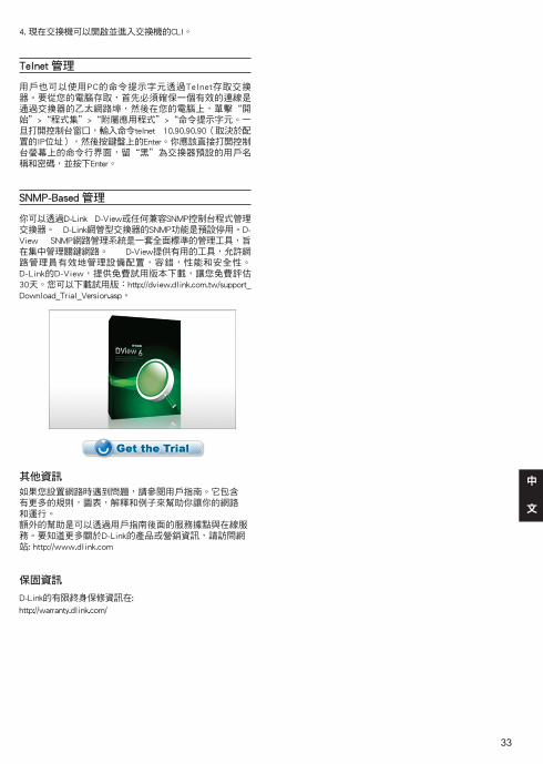
33
中
文
4. 現在交換機可以開啟並進入交換機的CLI。
Telnet 管理
用戶也可以使用PC的命令提示字元透過Telnet存取交換器。要從您的電腦存取,首先必須確保一個有效的連線是通過交換器的乙太網路埠,然後在您的電腦上,單擊“開始”>“程式集”>“附屬應用程式”>“命令提示字元。一旦打開控制台窗口,輸入命令telnet 10.90.90.90(取決於配置的IP位址),然後按鍵盤上的Enter。你應該直接打開控制台螢幕上的命令行界面,留“黑”為交換器預設的用戶名稱和密碼,並按下Enter。
SNMP-Based 管理
你可以透過D-Link D-View或任何兼容SNMP控制台程式管理交換器。 D-Link網管型交換器的SNMP功能是預設停用。D-View SNMP網路管理系統是一套全面標準的管理工具,旨在集中管理關鍵網路。 D-View提供有用的工具,允許網路管理員有效地管理設備配置,容錯,性能和安全性。 D-Link的D-View,提供免費試用版本下載,讓您免費評估30天。您可以下載試用版:http://dview.dlink.com.tw/support_Download_Trial_Version.asp。
其他資訊
如果您設置網路時遇到問題,請參閱用戶指南。它包含有更多的規則,圖表,解釋和例子來幫助你讓你的網路和運行。額外的幫助是可以透過用戶指南後面的服務據點與在線服務。要知道更多關於D-Link的產品或營銷資訊,請訪問網站: http://www.dlink.com
保固資訊
D-Link的有限終身保修資訊在:
http://warranty.dlink.com/
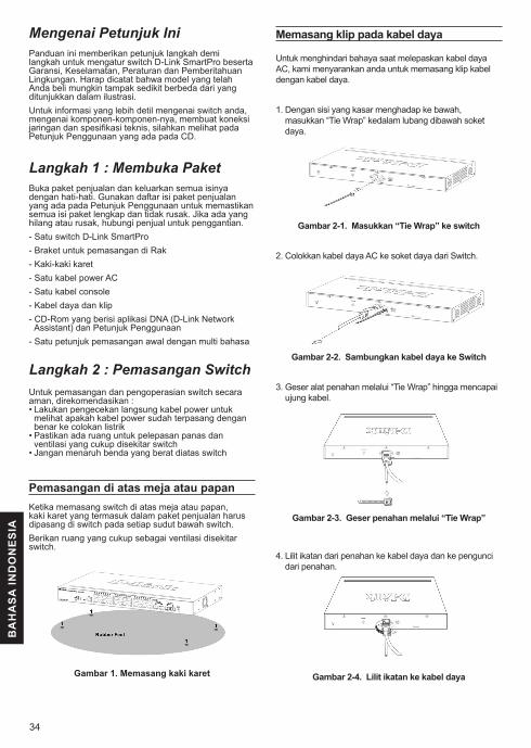
34
BA
HA
SA
IND
ON
ES
IA
Mengenai Petunjuk IniPanduan ini memberikan petunjuk langkah demi langkah untuk mengatur switch D-Link SmartPro beserta Garansi, Keselamatan, Peraturan dan Pemberitahuan Lingkungan. Harap dicatat bahwa model yang telah Anda beli mungkin tampak sedikit berbeda dari yang ditunjukkan dalam ilustrasi.Untuk informasi yang lebih detil mengenai switch anda, mengenai komponen-komponen-nya, membuat koneksi jaringan dan spesifikasi teknis, silahkan melihat pada Petunjuk Penggunaan yang ada pada CD.
Langkah 1 : Membuka PaketBuka paket penjualan dan keluarkan semua isinya dengan hati-hati. Gunakan daftar isi paket penjualan yang ada pada Petunjuk Penggunaan untuk memastikan semua isi paket lengkap dan tidak rusak. Jika ada yang hilang atau rusak, hubungi penjual untuk penggantian.- Satu switch D-Link SmartPro - Braket untuk pemasangan di Rak- Kaki-kaki karet- Satu kabel power AC- Satu kabel console - Kabel daya dan klip- CD-Rom yang berisi aplikasi DNA (D-Link Network
Assistant) dan Petunjuk Penggunaan- Satu petunjuk pemasangan awal dengan multi bahasa
Langkah 2 : Pemasangan SwitchUntuk pemasangan dan pengoperasian switch secara aman, direkomendasikan :• Lakukan pengecekan langsung kabel power untuk
melihat apakah kabel power sudah terpasang dengan benar ke colokan listrik
• Pastikan ada ruang untuk pelepasan panas dan ventilasi yang cukup disekitar switch
• Jangan menaruh benda yang berat diatas switch
Pemasangan di atas meja atau papan Ketika memasang switch di atas meja atau papan, kaki karet yang termasuk dalam paket penjualan harus dipasang di switch pada setiap sudut bawah switch.Berikan ruang yang cukup sebagai ventilasi disekitar switch.
Gambar 1. Memasang kaki karet
Memasang klip pada kabel daya
Untuk menghindari bahaya saat melepaskan kabel daya AC, kami menyarankan anda untuk memasang klip kabel dengan kabel daya.
1. Dengan sisi yang kasar menghadap ke bawah, masukkan “Tie Wrap” kedalam lubang dibawah soket daya.
Gambar 2-1. Masukkan “Tie Wrap” ke switch
2. Colokkan kabel daya AC ke soket daya dari Switch.
Gambar 2-2. Sambungkan kabel daya ke Switch
3. Geser alat penahan melalui “Tie Wrap” hingga mencapai ujung kabel.
Gambar 2-3. Geser penahan melalui “Tie Wrap”
4. Lilit ikatan dari penahan ke kabel daya dan ke pengunci dari penahan.
Gambar 2-4. Lilit ikatan ke kabel daya
35
BA
HA
SA
IND
ON
ES
IA
Pemasangan pada RakSwitch dapat dipasang pada rak dengan ukuran standar EIA 19 inci, dimana dapat ditempatkan pada ruang komunikasi/server dengan perangkat lainnya. Untuk memasang pada rack, pasang braket pada bagian samping switch (satu braket di setiap sisi) dan kencangkan dengan sekrup yang tersedia dalam paket penjualan.
Gambar 3. Memasang Braket
Kemudian, gunakan sekrup yang terdapat dalam penjualan rak untuk memasang switch ke rak.
Gambar 4. Memasang switch ke rak dengan ukuran standar
Langkah 3: Colokkan kabel power ACSekarang anda dapat menghubungkan kabel power AC ke port power dibelakang switch ke colokan listrik. (Direkomendasikan peralatan sudah di grounded dan dilengkapi dengan pelindung terhadap lonjakan listrik).
5. Kencangkan ikatan penahan hingga kabel daya terpasang dengan baik.
Gambar 2-5. Kencangkan ikatan kabel dayaGambar 5. Mencolokkan switch ke colokan listrik
Pemadaman ListrikSebagai tindakan pencegahan, kabel power harus dicabut jika terjadi pemadaman listrik. Ketika listrik kembali menyala, anda dapat kembali menghubungkan switch ke listrik.
Pilihan manajemenSistem ini dapat dikelola melalui port konsol di bagian panel depan/belakang atau dengan menggunakan Telnet. Pengguna juga dapat memilih manajemen berbasis web, yang dapat diakses melalui web browser. Setiap Switch harus diberikan Alamat IP, yang digunakan untuk komunikasi dengan SNMP Network Manager atau aplikasi TCP/IP lain (seperti BOOTP, TFTP). Alamat IP default Switch adalah 10.90.90.90. Pengguna dapat mengubah alamat IP switch untuk memenuhi spesifikasi skema alamat jaringan Anda.
Antar Muka Pengaturan Berbasiskan WebSetelah pemasangan secara fisik selesai dilakukan, anda dapat mengatur switch, me-monitor lampu LED dan menampilkan gambar statistik menggunakan web browser seperti Netscape Navigator (versi 6.2 atau lebih tinggi) atau Microsoft® Internet Explorer (versi 5.0 atau lebih tinggi)Anda membutuhkan perangkat berikut untuk memulai mengatur perangkat anda melalui web :
• Sebuah PC dengan koneksi ethernet RJ-45• Sebuah kabel Ethernet standar
Langkah 1 :Hubungkan kabel Ethernet dari port mana saja pada bagian depan switch ke port Ethernet pada PC.
Gambar 6. Kabel Ethernet yang sudah terhubung
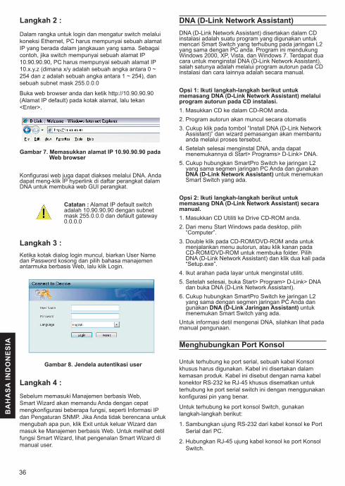
36
BA
HA
SA
IND
ON
ES
IA
Langkah 2 :
Dalam rangka untuk login dan mengatur switch melalui koneksi Ethernet, PC harus mempunyai sebuah alamat IP yang berada dalam jangkauan yang sama. Sebagai contoh, jika switch mempunyai sebuah alamat IP 10.90.90.90, PC harus mempunyai sebuah alamat IP 10.x.y.z (dimana x/y adalah sebuah angka antara 0 ~ 254 dan z adalah sebuah angka antara 1 ~ 254), dan sebuah subnet mask 255.0.0.0
Buka web browser anda dan ketik http://10.90.90.90 (Alamat IP default) pada kotak alamat, lalu tekan <Enter>.
Gambar 7. Memasukkan alamat IP 10.90.90.90 pada Web browser
Konfigurasi web juga dapat diakses melalui DNA. Anda dapat meng-klik IP hyperlink di daftar perangkat dalam DNA untuk membuka web GUI perangkat.
Catatan : Alamat IP default switch adalah 10.90.90.90 dengan subnet mask 255.0.0.0 dan default gateway 0.0.0.0
Langkah 3 :Ketika kotak dialog login muncul, biarkan User Name dan Password kosong dan pilih bahasa manajemen antarmuka berbasis Web, lalu klik Login.
Gambar 8. Jendela autentikasi user
Langkah 4 :Sebelum memasuki Manajemen berbasis Web, Smart Wizard akan memandu Anda dengan cepat mengkonfigurasi beberapa fungsi, seperti Informasi IP dan Pengaturan SNMP. Jika Anda tidak berencana untuk mengubah apa pun, klik Exit untuk keluar Wizard dan masuk ke Manajemen berbasis Web. Untuk melihat detil fungsi Smart Wizard, lihat pengenalan Smart Wizard di manual user.
DNA (D-Link Network Assistant)DNA (D-Link Network Assistant) disertakan dalam CD instalasi adalah suatu program yang digunakan untuk mencari Smart Switch yang terhubung pada jaringan L2 yang sama dengan PC anda. Program ini mendukung Windows 2000, XP, Vista, dan Windows 7. Terdapat dua cara untuk menginstal DNA (D-Link Network Assistant), salah satunya adalah melalui program autorun pada CD instalasi dan cara lainnya adalah secara manual.
Opsi 1: Ikuti langkah-langkah berikut untuk memasang DNA (D-Link Network Assistant) melalui program autorun pada CD instalasi.1. Masukkan CD ke dalam CD-ROM anda.2. Program autorun akan muncul secara otomatis3. Cukup klik pada tombol ”Install DNA (D-Link Network
Assistant)” dan wizard pemasangan akan membantu anda melalui proses tersebut.
4. Setelah selesai menginstal DNA, anda dapat menemukannya di Start> Programs> D-Link> DNA.
5. Cukup hubungkan SmartPro Switch ke jaringan L2 yang sama segmen jaringan PC Anda dan gunakan DNA (D-Link Network Assistant) untuk menemukan Smart Switch yang ada.
Opsi 2: Ikuti langkah-langkah berikut untuk memasang DNA (D-Link Network Assistant) secara manual.1. Masukkan CD Utiliti ke Drive CD-ROM anda.2. Dari menu Start Windows pada desktop, pilih
“Computer”.3. Double klik pada CD-ROM/DVD-ROM anda untuk
menjalankan menu autorun, atau klik kanan pada CD-ROM/DVD-ROM untuk membuka folder. Pilih DNA (D-Link Network Assistant) dan klik dua kali pada “Setup.exe”.
4. Ikut arahan pada layar untuk menginstal utiliti.5. Setelah selesai, buka Start> Program> D-Link> DNA
dan buka DNA (D-Link Network Assistant).6. Cukup hubungkan SmartPro Switch ke jaringan L2
yang sama dengan segmen jaringan PC Anda dan gunakan DNA (D-Link Jaringan Assistant) untuk menemukan Smart Switch yang ada.
Untuk informasi detil mengenai DNA, silahkan lihat pada manual pengunaan.
Menghubungkan Port Konsol
Untuk terhubung ke port serial, sebuah kabel Konsol khusus harus digunakan. Kabel ini disertakan dalam kemasan produk. Kabel ini disebut dengan nama kabel konektor RS-232 ke RJ-45 khusus disematkan untuk terhubung ke port serial switch ini dengan menggunakan konfigurasi pin yang benar.
Untuk terhubung ke port konsol Switch, gunakan langkah-langkah berikut:
1. Sambungkan ujung RS-232 dari kabel konsol ke Port Serial dari PC.
2. Hubungkan RJ-45 ujung kabel konsol ke port Konsol Switch.
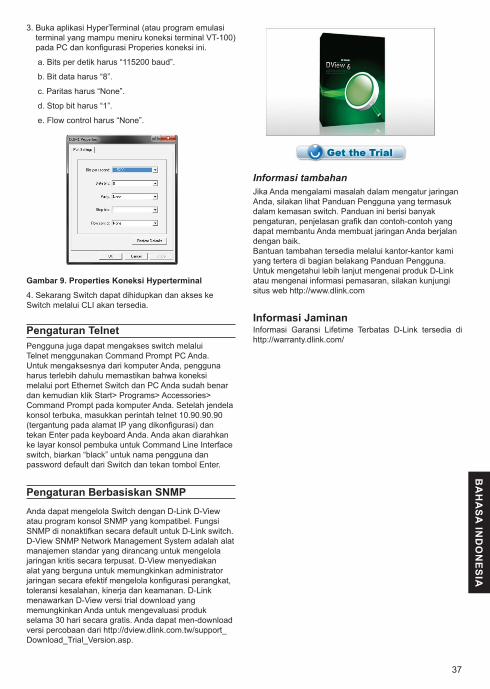
37
BA
HA
SA
IND
ON
ES
IA
3. Buka aplikasi HyperTerminal (atau program emulasi terminal yang mampu meniru koneksi terminal VT-100) pada PC dan konfigurasi Properies koneksi ini.
a. Bits per detik harus “115200 baud”.
b. Bit data harus “8”.
c. Paritas harus “None”.
d. Stop bit harus “1”.
e. Flow control harus “None”.
Gambar 9. Properties Koneksi Hyperterminal
4. Sekarang Switch dapat dihidupkan dan akses ke Switch melalui CLI akan tersedia.
Pengaturan TelnetPengguna juga dapat mengakses switch melalui Telnet menggunakan Command Prompt PC Anda. Untuk mengaksesnya dari komputer Anda, pengguna harus terlebih dahulu memastikan bahwa koneksi melalui port Ethernet Switch dan PC Anda sudah benar dan kemudian klik Start> Programs> Accessories> Command Prompt pada komputer Anda. Setelah jendela konsol terbuka, masukkan perintah telnet 10.90.90.90 (tergantung pada alamat IP yang dikonfigurasi) dan tekan Enter pada keyboard Anda. Anda akan diarahkan ke layar konsol pembuka untuk Command Line Interface switch, biarkan “black” untuk nama pengguna dan password default dari Switch dan tekan tombol Enter.
Pengaturan Berbasiskan SNMPAnda dapat mengelola Switch dengan D-Link D-View atau program konsol SNMP yang kompatibel. Fungsi SNMP di nonaktifkan secara default untuk D-Link switch. D-View SNMP Network Management System adalah alat manajemen standar yang dirancang untuk mengelola jaringan kritis secara terpusat. D-View menyediakan alat yang berguna untuk memungkinkan administrator jaringan secara efektif mengelola konfigurasi perangkat, toleransi kesalahan, kinerja dan keamanan. D-Link menawarkan D-View versi trial download yang memungkinkan Anda untuk mengevaluasi produk selama 30 hari secara gratis. Anda dapat men-download versi percobaan dari http://dview.dlink.com.tw/support_Download_Trial_Version.asp.
Informasi tambahanJika Anda mengalami masalah dalam mengatur jaringan Anda, silakan lihat Panduan Pengguna yang termasuk dalam kemasan switch. Panduan ini berisi banyak pengaturan, penjelasan grafik dan contoh-contoh yang dapat membantu Anda membuat jaringan Anda berjalan dengan baik.Bantuan tambahan tersedia melalui kantor-kantor kami yang tertera di bagian belakang Panduan Pengguna. Untuk mengetahui lebih lanjut mengenai produk D-Link atau mengenai informasi pemasaran, silakan kunjungi situs web http://www.dlink.com
Informasi Jaminan Informasi Garansi Lifetime Terbatas D-Link tersedia di http://warranty.dlink.com/
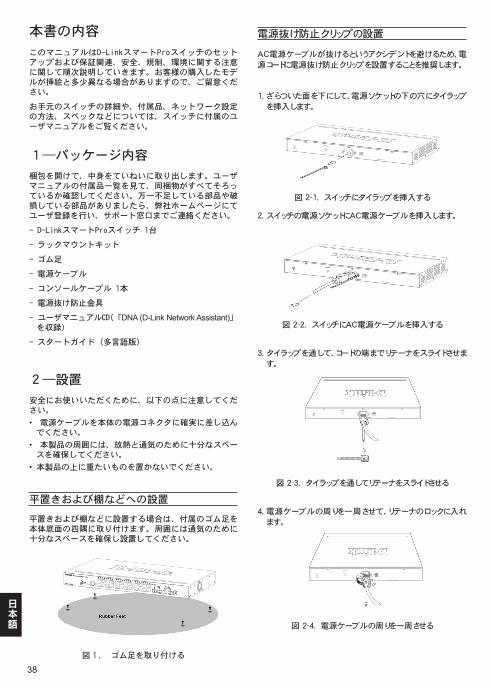
38
日本語
本書の内容
このマニュアルはD-LinkスマートProスイッチのセットアップおよび保証関連、安全、規制、環境に関する注意に関して順次説明していきます。お客様の購入したモデルが挿絵と多少異なる場合がありますので、ご留意ください。
お手元のスイッチの詳細や、付属品、ネットワーク設定の方法、スペックなどについては、スイッチに付属のユーザマニュアルをご覧ください。
1―パッケージ内容
梱包を開けて、中身をていねいに取り出します。ユーザマニュアルの付属品一覧を見て、同梱物がすべてそろっているか確認してください。万一不足している部品や破損している部品がありましたら、弊社ホームページにてユーザ登録を行い、サポート窓口までご連絡ください。
- D-LinkスマートProスイッチ 1台
- ラックマウントキット
- ゴム足
- 電源ケーブル
- コンソールケーブル 1本
- 電源抜け防止金具
- ユーザマニュアルCD(「DNA (D-Link Network Assistant)」を収録)
- スタートガイド(多言語版)
2―設置
安全にお使いいただくために、以下の点に注意してください。
• 電源ケーブルを本体の電源コネクタに確実に差し込んでください。
• 本製品の周囲には、放熱と通気のために十分なスペースを確保してください。
• 本製品の上に重たいものを置かないでください。
平置きおよび棚などへの設置
平置きおよび棚などに設置する場合は、付属のゴム足を本体底面の四隅に取り付けます。周囲には通気のために十分なスペースを確保し設置してください。
図1. ゴム足を取り付ける
電源抜け防止クリップの設置
AC電源ケーブルが抜けるというアクシデントを避けるため、電
源コードに電源抜け防止クリップを設置することを推奨します。
1. ざらついた面を下にして、電源ソケットの下の穴にタイラップ
を挿入します。
図 2-1. スイッチにタイラップを挿入する
2. スイッチの電源ソケットにAC電源ケーブルを挿入します。
図 2-2. スイッチにAC電源ケーブルを挿入する
3. タイラップを通して、コードの端までリテーナをスライドさせま
す。
図 2-3. タイラップを通してリテーナをスライドさせる
4. 電源ケーブルの周りを一周させて、リテーナのロックに入れ
ます。
図 2-4. 電源ケーブルの周りを一周させる
39
日本語
ラックに設置するとき
本製品はEIA規格の19インチラックに取り付けることができ、サーバルームなどに設置する場合に便利です。はじめに、ラックマウントキットを付属のネジで本製品の両側面に取り付けます。
図 3. ラックマウントキットを取り付ける
次に、付属のネジを使用して、スイッチをラックに固定します。
図 4. スイッチをラックに取り付ける
3―電源ケーブルの接続
電源ケーブルを本体背面の電源コネクタに接続し、もう一方をコンセントに差し込みます。(コンセントはアース付きでサージ対策のあるものをおすすめします。)
図 5. 電源ケーブルの接続
5. 電源コードが固定されるまでリテーナを締めます
図 2-5. 電源コードを固定する
停電の際には
停電の際には念のためコンセントを抜きます。電力が復旧してから、再度コンセントをつないでください。
管理オプション
このスイッチは、フロント/バックパネルのコンソールポートを介して管理するもしくはTelnetを使って管理することができます。また、お客様はWebブラウザを介してアクセスするWebベース管理を選択することもあるかもしれません。それぞれのスイッチは自身のIPアドレスをアサインされている必要があり、IPアドレスは、SNMPネットワーク管理もしくは他のTCP/IPアプリケーション(例:BOOTP、TFTP)での通信にも使われます。スイッチのデフォルトIPアドレスは10.90.90.90です。お客様はデフォルトIPアドレスをお使いのネットワークアドレススキームに合うように変更することができます。
Webベース管理インターフェイス
Webブラウザを使って、スイッチの設定、ステータスLEDのモニタリング、統計情報のグラフ表示などができます。使用可能なブラウザは、Netscape Navigator(バージョン6.2以降)やMicrosoft® Internet Explorer(バージョン5.0以降)などです。
ウェブブラウザを使ったスイッチの設定には、以下のものが必要です。
• イーサネットポート(RJ-45)を持つコンピュータ
• 標準的なイーサネットケーブル
ステップ1
イーサネットケーブルを使って、スイッチ前面のいずれかのポートとコンピュータのイーサネットポートを接続します。
図 6. イーサネットケーブルの接続
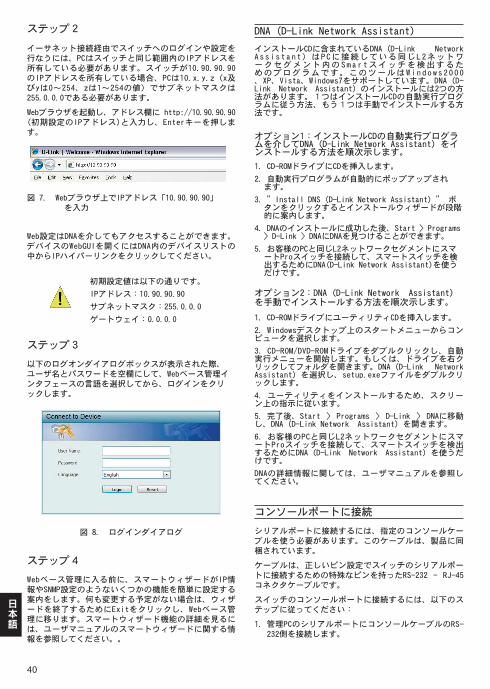
40
日本語
ステップ2
イーサネット接続経由でスイッチへのログインや設定を行なうには、PCはスイッチと同じ範囲内のIPアドレスを所有している必要があります。スイッチが10.90.90.90のIPアドレスを所有している場合、PCは10.x.y.z(x及びyは0~254、zは1~254の値)でサブネットマスクは255.0.0.0である必要があります。
Webブラウザを起動し、アドレス欄に http://10.90.90.90 (初期設定のIPアドレス)と入力し、Enterキーを押します。
図 7. Webブラウザ上でIPアドレス「10.90.90.90」を入力
Web設定はDNAを介してもアクセスすることができます。デバイスのWebGUIを開くにはDNA内のデバイスリストの中からIPハイパーリンクをクリックしてください。
初期設定値は以下の通りです。
IPアドレス:10.90.90.90
サブネットマスク:255.0.0.0
ゲートウェイ:0.0.0.0
ステップ3
以下のログオンダイアログボックスが表示された際、ユーザ名とパスワードを空欄にして、Webベース管理インタフェースの言語を選択してから、ログインをクリックします。
図 8. ログインダイアログ
ステップ4
Webベース管理に入る前に、スマートウィザードがIP情報やSNMP設定のようないくつかの機能を簡単に設定する案内をします。何も変更する予定がない場合は、ウィザードを終了するためにExitをクリックし、Webベース管理に移ります。スマートウィザード機能の詳細を見るには、ユーザマニュアルのスマートウィザードに関する情報を参照してください。。
DNA (D-Link Network Assistant)
インストールCDに含まれているDNA(D-Link Network Assistant)はPCに接続している同じL2ネットワークセグメント内のSma r tスイッチを検出するためのプログラムです。このツールはWindows2000、XP、Vista、Windows7をサポートしています。DNA(D-Link Network Assistant)のインストールには2つの方法があります。1つはインストールCDの自動実行プログラムに従う方法、もう1つは手動でインストールする方法です。
オプション1:インストールCDの自動実行ブログラムを介してDNA(D-Link Network Assistant)をインストールする方法を順次示します。
1.CD-ROMドライブにCDを挿入します。
2.自動実行プログラムが自動的にポップアップされます。
3.”Install DNS(D-Link Network Assistant)” ボタンをクリックするとインストールウィザードが段階的に案内します。
4.DNAのインストールに成功した後、Start > Programs > D-Link > DNAにDNAを見つけることができます。
5.お客様のPCと同じL2ネットワークセグメントにスマートProスイッチを接続して、スマートスイッチを検出するためにDNA(D-Link Network Assistant)を使うだけです。
オプション2:DNA(D-Link Network Assistant)を手動でインストールする方法を順次示します。
1.CD-ROMドライブにユーティリティCDを挿入します。
2.Windowsデスクトップ上のスタートメニューからコンピュータを選択します。
3.CD-ROM/DVD-ROMドライブをダブルクリックし、自動実行メニューを開始します。もしくは、ドライブを右クリックしてフォルダを開きます。DNA(D-Link Network Assistant)を選択し、setup.exeファイルをダブルクリックします。
4.ユーティリティをインストールするため、スクリーン上の指示に従います。
5.完了後、Start > Programs > D-Link > DNAに移動し、DNA(D-Link Network Assistant)を開きます。
6.お客様のPCと同じL2ネットワークセグメントにスマートProスイッチを接続して、スマートスイッチを検出するためにDNA(D-Link Network Assistant)を使うだけです。
DNAの詳細情報に関しては、ユーザマニュアルを参照してください。
コンソールポートに接続
シリアルポートに接続するには、指定のコンソールケーブルを使う必要があります。このケーブルは、製品に同梱されています。
ケーブルは、正しいピン設定でスイッチのシリアルポートに接続するための特殊なピンを持ったRS-232 - RJ-45コネクタケーブルです。
スイッチのコンソールポートに接続するには、以下のステップに従ってください:
1. 管理PCのシリアルポートにコンソールケーブルのRS-232側を接続します。
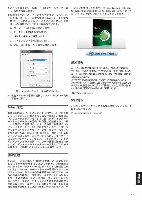
41
日本語
2. スイッチのコンソールポートにコンソールケーブルのRJ-45側を接続します。
3. 管理PC上でハイパーターミナルアプリケーション(もしくは、VT-100ターミナル接続をエミュレート可能な他のターミナルエミュレーションプログラム)を開き、この接続のプロパティの設定を行います。
a. ボーレートに115200を設定します。
b. データビットに8を設定します。
c. パリティをNoneに設定します。
d. ストップビットを1に設定します。
e. フローコントロールをNoneに設定します。
図9. ハイパーターミナル接続プロパティ
4. 現在スイッチは電源が起動し、スイッチのCLIが利用可能な状態です。
Telnet管理
お客様のPCのコマンドプロンプトを利用してTelnetを介してスイッチにアクセスすることもできます。お客様のコンピュータからアクセスするには、まずスイッチのイーサネットポートとお客様のPCが正しく接続されていることを確認する必要があります。その後、お客様のコンピュータ上で、スタート> プログラム> アクセサリ> コマンドプロンプトをクリックします。コンソールウィンドウを開いた後、telnet 10.90.90.90(設定しているIPアドレスによります)とコマンドを入力し、キーボード上でEnterを押下してください。スイッチのコマンドラインインタフェースを開くコンソール画面に接続されますので、デフォルトのスイッチのユーザ名とパスワードの場合は、“空欄”のままEnterキーを押下します。
SNMP管理
D-Link D-ViewもしくはSNMP互換コンソールプログラムでスイッチを管理することができます。SNMP機能はD-Linkマネージドスイッチではデフォルトで無効になっています。D-View SNMPネットワーク管理システムはクリティカルネットワークの集中管理のためにデザインされた統合的な標準ベース管理ツールです。D-Viewはネットワーク管理者が、デバイス設定、フォルトトレランス、パフォーマンス、セキュリティを効果的に管理するために役立つツールです。D-Linkはダウンロードして30日間製品を評価することができる、D-Viewトライアルバ
ージョンを提供しています。http://dview.dlink.com.tw/support_Download_Trial_Version.asp からトライアルバージョンをダウンロードすることができます。
追加情報
ネットワーク設定で問題が生じた場合は、スイッチに同梱されているユーザガイドを参照してください。ユーザガイドは、多くのルール、図、説明、例を含んでおり、ネットワークを構築・運用するのに役立ちます。ユーザガイドの最後もしくは、オンラインで記載されているD-Linkの各オフィスを通して更なるサポートを受けることができます。D-Link製品やマーケティング情報についてより詳しく知りたい場合は、下記のWebサイトをご確認ください。
http://www.dlink.com
保証情報
D-Linkリミテッドライフタイム保証情報については、下記をご覧ください。
http://warranty.dlink.com/
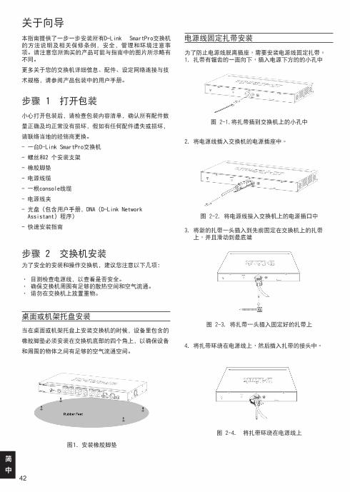
42
簡
中
关于向导
本指南提供了一步一步安装所有D-Link SmartPro交换机的方法说明及相关保修条例,安全,管理和环境注意事项。请注意您所购买的产品可能与指南中的图片所示略有不同。
更多关于您的交换机详细信息、配件、设定网络连接与技
术规格,请参阅产品包装中的用户手册。
步骤 1 –打开包装
小心打开包装后,请检查包装内容清单,确认所有配件数
量正确及均正常没有损坏,假如有任何配件遗失或损坏,
请联络当地的经销商更换。
- 一台D-Link SmartPro交换机
- 螺丝和2 个安装支架
- 橡胶脚垫
- 电源线缆
- 一根console线缆
- 电源线夹
- 光盘(包含用户手册,DNA (D-Link Network Assistant) 程序)
- 快速安装指南
步骤 2 –交换机安装–为了安全的安装和操作交换机,建议您注意以下几项:
•–目测检查电源线,以查看是否安全。•–确保交换机周围有足够的散热空间和空气流通。•–请勿在交换机上放置重物。
桌面或机架托盘安装–
当在桌面或机架托盘上安装交换机的时候,设备里包含的
橡胶脚垫必须安装在交换机底部的四个角上,以确保设备
和周围的物体之间有足够的空气流通空间。
图1. 安装橡胶脚垫–––
電源線固定紮帶安裝
為了防止電源線脫離插座,需要安裝電源線固定紮帶。1. 紮帶有鋸齒的一面向下,插入電源下方的的小孔中
圖 2-1.將紮帶插到交換機上的小孔中
2. 將電源線插入交換機的電源插座中。
圖 2-2. 將電源線接入交換機上的電源插口中
3. 將新的紮帶一頭插入到先前固定在交換機上的紮帶上,並且滑動到最底端
圖 2-3. 將紮帶一頭插入固定好的紮帶上
4. 將紮帶環繞在電源線上,然後插入紮帶的接頭中。
圖 2-4. 將紮帶環繞在電源線上
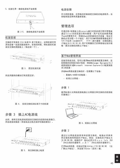
43
簡
中
电源故障
作为预防措施,在停电的时候请把交换机的电源断开。当供电恢复后再将其重新连接。
管理选项
可通過前/後面板上的console端口對系統進行帶外管理或通過Telnet對系統進行帶內管理。用戶也可選擇使用基于web的管理方式,即通過web瀏覽器來訪問設備。每台交換機必須分配一個IP地址,用于與SNMP網絡管理器或其它TCP/IP應用(比如BOOTP, TFTP)進行通信。交換機默認IP地址為10.90.90.90.用戶可根據自己的網絡地址劃分規格,更改交換機的默認IP地址。
基于Web管理界面
设备安装成功后,您可以使用Web浏览器来配置交换机、监 控网络状态和显示统计信息,例如Netscape Navigator(6.2或更高版本)或Microsoft– Internet Explorer(5.0或更高版本)浏览器。
开始Web界面设置交换机时,您需要以下设备:
• 配备RJ-45网卡的电脑。
• 标准以太网线。
步骤 1
使用标准以太网线连接电脑以太网接口和交换机的前面板任意端口。
– 图 6. 连接以太网线
步骤 2
通过以太网线连接登录和设置交换机,电脑必须具有同交换机相同网段的IP地址。例如:交换机的IP地址为10.90.90.90,电脑的IP 地址必须为10.x.y.z (x/y 为0 ~ 254之间的任意数字,z 为 1 ~ 254之间的任意数字)。
打开Web浏览器,在地址栏输入http://10.90.90.90 (出厂默认IP地址) ,然后按下Enter(回车)键。
机架安装–
交换机可安装在 EIA 标准19 英寸机架上,这种机架可同其他设备一起放在配线柜中。安装的时候,将机架的托架装在交换机侧面板上(每边装一个)。
图 3. 固定机架托架
然后用提供的螺丝钉将其固定好。
图 4. 安装交换机到标准尺寸的机架
步骤 3 –插上AC电源线
此时,请将交流电源线连接到交换机的后面的电源插口,然后连接到插座(有接地及过电压保护的插座最佳)。
– 图 5. 将交换机插上电源
5. 拉緊紮帶,確保電源線不會脫落
圖 2-5. 確保電源線不會脫落
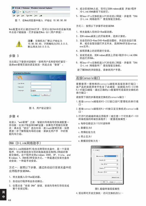
44
簡
中
–图 7. 在Web浏览器中输入 IP地址 10.90.90.90
Web配置也可以通過DNA打開。您可以在DNA中的設備列表中點擊IP超鏈接,打開設備的Web GUI(用戶界面)。
注意:交换机出厂默认IP地址为10.90.90.90、子网掩码为255.0.0.0,默认网关为0.0.0.0。
步骤 3
當出現以下登錄對話框時,請將用戶名和密碼欄留空,–選擇web管理頁面的語言類別,然後點擊“登錄”。
图 8. 用户验证窗口
步骤 4
在進入“web管理”之前,智能嚮導將指導您快速配置一些功能,比如IP信息和SNMP設置。如果您不想做任何更改,請點擊“退出”退出嚮導,進入web管理頁面。如想更進一步瞭解智能嚮導的功能,請參見用戶手册中的智能嚮導介紹。
DNA(D-Link网络助手)
DNA(D-Link网络助手)包含在附带的光盘中,是一个发现程序,可以帮助找到与您的电脑连接在相同L2网段的智能交换机。这个程序支持windows 2000, XP, Vista, and Windows 7。DNA有2种安装方式。一种是通过安装光盘自动安装;一种是手动安装。
方式一:按照以下步骤,通过自动运行安装光盘中的
应用程序安装DNA。
1、将光盘插入CD-Rom驱动器。
2、自动运行程序将会自动弹出。
3、 仅需点击“安装 DNA”按钮,安装向导将引导您完成整个安装过程。
4、 成功安装DNA之后,您可以到Windows桌面 开始>程序>D-Link>DNA路径下找到它。
5、 將SmartPro交換機接入PC所在的L2網段,並使用“DNA (D-Link 網絡助手)”查找智能交換機。
方式二:按照以下步骤手动安装DNA
1、将光盘插入您的CD-Rom驱动器。
2、在Windows桌面上的开始菜单,选择计算机。
3、 双击您的CD-Rom/DVD-Rom驱动图标,开启自动运行菜单,或右击驱动器打开文件夹,选择DNA并双击setup.exe文件。
4、按照屏幕上的说明进行安装。
5、 安装完成后,到Windows桌面上开始>程序>D-Link>DNA然后打开DNA。
6、 將SmartPro交換機接入PC所在的L2網段,並使用“DNA (D-Link 網絡助手)”查找智能交換機。
欲了解DNA的详细信息,请参阅用户手册。
連接Console端口
需要使用一根特殊的console綫纜來連接到串行端口。該產品的裝箱清單中包含了此綫纜。該綫纜為RS-232轉RJ-45接口綫纜,通過正確的pin配置即可連接到交換機的串行端口。
請按照下面的步驟連接交換機的console端口:
1. 連接console綫纜的RS-232接口至PC管理機的串行端口。
2. 連接console綫纜的RJ-45接口至交換機的console端口。
3. 打開PC的超級終端應用程序(或任意一個可仿真VT-100終端連接的終端仿真程序),配置連接屬性。
a.每秒位數設為115200波特率
b.數據位為8
c.奇偶校驗為無
d.停止位為1
e.數據流控制為無。
圖9.超級終端連接屬性
4.現在即可開啟交換機,訪問交換機的CLI。
45
簡
中
Telnet 管理
用戶也可通過Telnet,使用PC的命令提示符來訪問交換機。如想從您的計算機上訪問交換機,用戶必須首先確保交換機和您的PC已經建立有效連接,再點擊計算機上的開始>程序>附件>命令提示符。Console窗口打開後,輸入命令telnet 10.90.90.90(配置的IP地址),按下鍵盤上的Enter健後,彈出交換機的命令行界面窗口,默認用戶名和密碼兩欄留為空白,並按下Enter健。
基于SNMP管理
您可以通過D-Link D-View或任意一個兼容SNMP的console程序來管理交換機。對于D-Link 可管理交換機,SNMP功能默認為禁用。D-View SNMP網絡管理系統是一款綜合性的標準管理工具,設計用于對中心網絡進行集中式管理。網絡管理員使用D-View的工具,能有效管理設備配置,容錯性,性能和安全性。D-Link提供免費的D-View試用版下載,允許您30天內免費使用該產品。您可以從http://dview.dlink.com.tw/support_Download_Trial_Version.asp上下載試用版本。
其它信息––
如果在網絡設置時遇到問題,請參考交換機附帶的用戶手冊。手冊裏包括更多的規則、圖表、解釋和舉例,可以幫助您進行網絡連接及正常運行。更多幫助可查看用戶指南背後的技術服務電話或在綫詢問技術服務人員。欲瞭解更多的D-Link產品或市場信息,請訪問以下網頁http://www.dlink.com。
保修信息
D-Link保修信息请访问以下网页
http://warranty.dlink.com/
46
FCC Warning This equipment has been tested and found to comply with the limits for a Class A digital device, pursuant to Part 15 of the FCC Rules. These limits are designed to provide reasonable protection against harmful interference when the equipment is operated in a commercial environment. This equipment generates, uses, and can radiate radio frequency energy and, if not installed and used in accordance with this manual, may cause harmful interference to radio communications. Operation of this equipment in a residential area is likely to cause harmful interference in which case the user will be required to correct the interference at his own expense.
CE Mark Warning This is a Class A product. In a domestic environment, this product may cause radio interference in which case the user may be required to take adequate measures.
Warnung! Dies ist ein Produkt der Klasse A. Im Wohnbereich kann dieses Produkt Funkstoerungen verursachen. In diesem Fall kann vom Benutzer verlangt werden, angemessene Massnahmen zu ergreifen.
Precaución! Este es un producto de Clase A. En un entorno doméstico, puede causar interferencias de radio, en cuyo case, puede requerirse al usuario para que adopte las medidas adecuadas.
Attention! Ceci est un produit de classe A. Dans un environnement domestique, ce produit pourrait causer des interférences radio, auquel cas l`utilisateur devrait prendre les mesures adéquates.
Attenzione! Il presente prodotto appartiene alla classe A. Se utilizzato in ambiente domestico il prodotto può causare interferenze radio, nel cui caso è possibile che l`utente debba assumere provvedimenti adeguati.
VCCI Warning
この装置は、クラスA情報技術装置です。この装置を家庭環境で使用すると電波妨害を引き起こすことがあります。この場合には使用者が適切な 対策を講ずるよう要求されることがあります。VCCI-A
警告使用者:
這是甲類的資訊產品,在居住的環境中使用時,可能會造成射頻干擾,在這種情況下,使用者會被要求採取某些適當的對策。
SFP (Mini-GBIC), XENPAK, and XFP Regulatory Compliance Networks pluggable optical modules meet the following regulatory requirements:
• Class 1 Laser Product
• EN60825-1+A2:2001 or later, European laser standard
• FCC 21 CFR Chapter 1, Subchapter J in accordance with FDA & CDRH requirements
Warranty InformationThe D-Link Limited Lifetime Warranty information is available at http://warranty.dlink.com/
SAFETY INSTRUCTIONSPlease adhere to the following safety guidelines to help ensure your own personal safety and protect your system from potential damage. Any acts taken that are inconsistent with ordinary use of the product, including improper testing, etc., and those not expressly approved by D-Link may result in the loss of product warranty.
Unless expressly approved by an authorized representative of D-Link in writing, you may not and may not permit others to:
• Disassemble or reverse engineer the device or attempt to derive source code (underlying ideas, algorithms, or structure) from the device or from any other information provided by
D-Link, except to the extent that this restriction is expressly prohibited by local law.
• Modify or alter the device.• Remove from the device any product identification or other
notices, including copyright notices and patent markings, if any.
To reduce the risk of bodily injury, electrical shock, fire, and damage to the device and other equipment, observe the following precautions:
Power Sources• Observe and follow service markings.• Do not push any objects into the openings of your device unless
consistent with the authorized operation of the device. Doing so can cause a fire or an electrical shock by shorting out interior components.
• The powering of this device must adhere to the power specifications indicated for this product.
• Do not overload wall outlets and/or extension cords as this will increase the risk of fire or electrical shock.
• Do not rest anything on the power cord or on the device (unless the device is made and expressly approved as suitable for stacking).
• Position system cables and power cables carefully; route cables so that they cannot be stepped on or tripped over. Be sure that nothing rests on any cables.
• Operate the device only from the type of external power source indicated on the electrical ratings label.
• To help avoid damaging your device, be sure the voltage selection switch (if provided) on the power supply is set to match the power available at your location.
• Also be sure that attached devices are electrically rated to operate with the power available in your location.
• Use only approved power cable(s). If you have not been provided a power cable for your device or for any AC-powered option intended for your device, purchase a power cable that is approved for use in your country and is suitable for use with your device. The power cable must be rated for the device and for the voltage and current marked on the device’s electrical ratings label. The voltage and current rating of the cable should be greater than the ratings marked on the device.
• To help prevent an electrical shock, plug the device and peripheral power cables into properly grounded electrical outlets. These cables are equipped with three-prong plugs to help ensure proper grounding. Do not use adapter plugs or remove the grounding prong from a cable. If you must use an extension cable, use a 3-wire cable with properly grounded plugs.
• Observe extension cable and power strip ratings. Ensure that the total ampere rating of all products plugged into the extension cable or power strip does not exceed 80 percent of the ampere ratings limit for the extension cable or power strip.
• To help protect your device from sudden, transient increases and decreases in electrical power, use a surge suppressor, line conditioner, or uninterruptible power supply (UPS).
• Do not modify power cables or plugs. Consult a licensed electrician or your power company for site modifications. Always follow your local/national wiring rules.
• When connecting or disconnecting power to hot-pluggable power supplies, if offered with your device, observe the following guidelines:
• Install the power supply before connecting the power cable to the power supply.
• Unplug the power cable before removing the power supply.• If the system has multiple sources of power, disconnect power
from the device by unplugging all power cables from the power supplies.
仅适用于海拔2000米以下地区安全使用
47
Servicing/Disassembling• Do not service any product except as expressly set forth in your
system documentation.• Opening or removing covers that are marked with the triangular
symbol with a lightning bolt may expose you to an electrical shock. Only a trained service technician should service components inside these compartments.
• To reduce the risk of electrical shock, never disassemble this device. None of its internal parts are user-replaceable; therefore, there is no reason to access the interior.
• Do not spill food or liquids on your system components, and never operate the device in a wet environment. If the device gets wet, see the appropriate section in your troubleshooting guide or contact your trained service provider.
• Use the device only with approved equipment.• Move products with care; ensure that all casters and/or
stabilizers are firmly connected to the system. Avoid sudden stops and uneven surfaces.
Environment• Do not use this device near water (e.g. near a bathtub, sink,
laundry tub, fish tank, in a wet basement or near a swimming pool).
• Do not use this device in areas with high humidity.• This device must not be subjected to water or condensation.• Keep your device away from radiators and heat sources. Also,
do not block cooling vents.
Cleaning• Always unplug the power before cleaning this device.• Do not use liquid or aerosol cleaners of any kind. Use only
compressed air that is recommended for electronic devices.• Use a dry cloth for cleaning.
PROTECTING AGAINST ELECTROSTATIC DISCHARGE
Static electricity can harm delicate components inside your system. To prevent static damage, discharge static electricity from your body before you touch any of the electronic components, such as the microprocessor. You can do so by periodically touching an unpainted metal surface on the chassis.You can also take the following steps to help prevent damage from electrostatic discharge (ESD):
1. When unpacking a static-sensitive component from its shipping carton, do not remove the component from the antistatic packing material until you are ready to install the component in your system. Just before unwrapping the antistatic packaging, be sure to discharge static electricity from your body.
2. When transporting a sensitive component, first place it in an antistatic container or packaging.
3. Handle all sensitive components in a static-safe area. If possible, use antistatic floor pads, workbench pads, and an antistatic grounding str
INSTRUCCIONES DE SEGURIDADPor favor siga las siguientes instrucciones de seguridad para garantizar su propia seguridad personal y proteger el equipo de posibles daños. Cualquier acto realizado que sea incompatible con el uso normal del producto, incluyendo pruebas no apropiadas, etc., y aquellos que no estén expresamente autorizados por D-Link pueden dar lugar a la pérdida de la garantía del producto.
A menos que estén expresamente aprobados por escrito por un representante autorizado de D-Link, usted no puede no puede:
• Desmontar o alterar el diseño del dispositivo o intentar obtener el código fuente (ideas subyacentes, algoritmos, o estructura del mismo) del dispositivo o de cualquier otra información proporcionada por D-Link, salvo en el caso en que esta restricción esté expresamente prohibida por la ley local.
• Modificar o alterar el dispositivo.• Retirar la identificación del producto u otras notificaciones,
incluyendo las notificaciones de copyright y marcado de patente, si fuera el caso.
Para reducir el riesgo de lesiones personales, descargas eléctricas, incendios y daños al aparato y otro equipamiento, tome las siguientes precauciones:
Fuentes de alimentación• Lea y siga atentamente las instrucciones de uso.• No introduzca ningún objeto en las aberturas de su dispositivo. Si lo
hace, puede provocar un incendio o recibir una descarga eléctrica debido a un cortocircuito de los componentes internos.
• El suministro eléctrico debe cumplir con las especificaciones de alimentación indicadas para este producto.
• No sobrecargue los enchufes de pared y / o cables de extensión ya que esto aumentará el riesgo de producir un incendio o recibir una descarga eléctrica.
• No apoye nada sobre el cable de alimentación o encima el dispositivo (a menos que el dispositivo esté diseñado y expresamente aprobado para ello).
• Coloque los cables del equipo y de la fuente de alimentación con cuidado, de forma que no se puedan pisar o tropezar fácilmente con ellos. Asegúrese de que no apoya nada sobre los cables.
• Utilice el dispositivo sólo con una fuente de alimentación externa que cumpla con las especificaciones eléctricas de la etiqueta.
• Para ayudar a evitar daños en el dispositivo, asegúrese de que el selector de voltaje (si existe) de la fuente de alimentación está ajustado para la tensión disponible en su localidad.
• Asegúrese también de que los dispositivos conectados estén clasificados eléctricamente para funcionar con la tensión disponible en su ubicación.
• Utilice únicamente cables de alimentación aprobados. Si el equipo no viniera con cable de alimentación o con cualquier otra opción de alimentación para corriente alterna, compre un cable de alimentación que esté aprobado para uso en su país y sea adecuado para su uso con el dispositivo. El cable de alimentación debe estar aprobado para el dispositivo y para el voltaje/corriente marcado en la etiqueta de especificaciones eléctricas que incluye el dispositivo, debiendo ser el valor de voltaje/corriente del cable superior al de las especificaciones.
• Para ayudar a prevenir una descarga eléctrica, conecte el dispositivo en enchufes que dispongan de su correspondiente toma de tierra. Los cables están equipados con enchufes de tres clavijas para garantizar una conexión a tierra adecuada. No utilice adaptadores ni retire la clavija de conexión a tierra de un cable. Si tiene que utilizar un cable de extensión, utilice un cable de 3 hilos con enchufes adecuadamente conectados a tierra.
• Asegúrese de que el amperaje total de todos los productos conectados al cable de extensión o regleta de alimentación no sea superior al 80 por ciento del amperaje límite del cable de extensión o de la regleta.
• Para ayudar a proteger el dispositivo de cambios repentinos, transitorios o disminuciones de la señal eléctrica, utilice un supresor de sobretensiones, un acondicionador de línea, o una fuente de alimentación ininterrumpida (SAI).
• No modifique los cables de alimentación o los enchufes. Consulte a un electricista autorizado o con la compañía eléctrica para realizar las modificaciones necesarias. Siga siempre la normativa de cableado local/nacional.
• Al conectar o desconectar la alimentación de las fuentes de alimentación conectables en caliente, si fuera el caso de su dispositivo, siga las siguientes pautas:

48
EUROPEAN COMMUNITY DECLARATION OF CONFORMITY
WARNING STATEMENTThe power outlet should be nearby the device and easily accessible.
Česky [Czech]
D-Link Corporation tímto prohlašuje, že tento je ve shodě se základními požadavky a dalšími příslušnými ustanoveními směrnice 1999/5/ES.
Dansk [Danish]
Undertegnede D-Link Corporation erklærer herved, at følgende udstyr overholder de væsentlige krav og øvrige relevante krav i direktiv 1999/5/EF.
Deutsch [German]
Hiermit erklärt D-Link Corporation, dass sich das Gerät in Übereinstimmung mit den grundlegenden Anforderungen und den übrigen einschlägigen Bestimmungen der Richtlinie 1999/5/EG befindet.
Eesti [Estonian]
Käesolevaga kinnitab D-Link Corporation seadme vastavust direktiivi 1999/5/EÜ põhinõuetele ja nimetatud direktiivist tulenevatele teistele asjakohastele sätetele.
EnglishHereby, D-Link Corporation, declares that this is in compliance with the essential requirements and other relevant provisions of Directive 1999/5/EC.
Español [Spanish]
Por medio de la presente D-Link Corporation declara que el cumple con los requisitos esenciales y cualesquiera otras disposiciones aplicables o exigibles de la Directiva 1999/5/CE.
Ελληνική [Greek]
ΜΕ ΤΗΝ ΠΑΡΟΥΣΑD-Link Corporation ΔΗΛΩΝΕΙ ΟΤΙ ΣΥΜΜΟΡΦΩΝΕΤΑΙ ΠΡΟΣ ΤΙΣ ΟΥΣΙΩΔΕΙΣ ΑΠΑΙΤΗΣΕΙΣ ΚΑΙ ΤΙΣ ΛΟΙΠΕΣ ΣΧΕΤΙΚΕΣ ΔΙΑΤΑΞΕΙΣ ΤΗΣ ΟΔΗΓΙΑΣ 1999/5/ΕΚ.
Français [French]
Par la présente D-Link Corporation déclare que l'appareil est conforme aux exigences essentielles et aux autres dispositions pertinentes de la directive 1999/5/CE.
Italiano [Italian]
Con la presente D-Link Corporation dichiara che questo è conforme ai requisiti essenziali ed alle altre disposizioni pertinenti stabilite dalla direttiva 1999/5/CE.
Latviski [Latvian]
Ar šo D-Link Corporation deklarē, ka atbilst Direktīvas 1999/5/EK būtiskajām prasībām un citiem ar to saistītajiem noteikumiem.
Lietuvių [Lithuanian]
Šiuo D-Link Corporation deklaruoja, kad šis atitinka esminius reikalavimus ir kitas 1999/5/EB Direktyvos nuostatas.
Nederlands [Dutch]
Hierbij verklaart D-Link Corporation dat het toestel in overeenstemming is met de essentiële eisen en de andere relevante bepalingen van richtlijn 1999/5/EG.
Malti [Maltese]
Hawnhekk, D-Link Corporation, jiddikjara li dan jikkonforma mal-ħtiġijiet essenzjali u ma provvedimenti oħrajn relevanti li hemm fid-Dirrettiva 1999/5/EC.
Magyar [Hungarian]
Alulírott, D-Link Corporation nyilatkozom, hogy a megfelel a vonatkozó alapvetõ követelményeknek és az 1999/5/EC irányelv egyéb elõírásainak.
Polski [Polish]
Niniejszym D-Link Corporation oświadcza, że jest zgodny z zasadniczymi wymogami oraz pozostałymi stosownymi postanowieniami Dyrektywy 1999/5/EC.
PortuguêsPortuguese]
D-Link Corporation declara que este D-Link Corporation está conforme com os requisitos essenciais e outras disposições da Directiva 1999/5/CE.
Slovensko [Slovenian]
D-Link Corporation izjavlja, da je ta v skladu z bistvenimi zahtevami in ostalimi relevantnimi določili direktive 1999/5/ES.
Slovensky [Slovak]
D-Link Corporation týmto vyhlasuje, že spĺňa základné požiadavky a všetky príslušné ustanovenia Smernice 1999/5/ES.
Suomi [Finnish]
D-Link Corporation vakuuttaa täten että tyyppinen laite on direktiivin 1999/5/EY oleellisten vaatimusten ja sitä koskevien direktiivin muiden ehtojen mukainen.
Svenska [Swedish]
Härmed intygar D-Link Corporation att denna står I överensstämmelse med de väsentliga egenskapskrav och övriga relevanta bestämmelser som framgår av direktiv 1999/5/EG.
Íslenska [Icelandic]
Hér með lýsir D-Link Corporation yfir því að er í samræmi við grunnkröfur og aðrar kröfur, sem gerðar eru í tilskipun 1999/5/EC.
Norsk [Norwegian]
D-Link Corporation erklærer herved at utstyret er i samsvar med de grunnleggende krav og øvrige relevante krav i direktiv 1999/5/EF.
• Instale la fuente de alimentación antes de proporcionar alimentación a la misma.
• Desconecte la alimentación antes de retirar el cable de alimentación.• Si el sistema tiene múltiples fuentes de alimentación, desconecte
la alimentación del mismo, y desenchufe todos los cables de alimentación de las fuentes de alimentación.
• En el caso de que la fuente de alimentación sea el dispositivo de desconexión del equipo. La base de toma de corriente debe estar cerca del equipo y ser fácilmente accesible.
Manipulación/ Desmontaje• No manipule el producto, salvo que esté expresamente establecido
en la documentación del equipo.• Si abre o retira las cubiertas que están marcadas con el símbolo
triangular con un rayo puede exponerse a una descarga eléctrica. Sólo un técnico cualificado debe reparar los componentes dentro de estos compartimientos.
• Para reducir el riesgo de descarga eléctrica, no desmonte el dispositivo. Ninguno de sus partes internas es sustituible por el usuario, por lo tanto, no hay ninguna razón para acceder al interior.
• No derrame comida ni líquidos sobre los componentes del sistema, y nunca utilice el dispositivo en un ambiente húmedo. Si el dispositivo se moja, consulte la sección correspondiente a solución de problemas o contacte con su proveedor.
• Utilice el dispositivo sólo con equipamiento aprobado.• Mueva los productos con cuidado; asegúrese de que todos los
estabilizadores están firmemente sujetos al equipo. Evite las detenciones repentinas y las superficies irregulares.
Medio Ambiente• No utilice este aparato cerca del agua (por ejemplo, cerca de una
bañera, fregadero, lavadero, peceras, en un sótano húmedo o cerca de una piscina).
• No utilice este dispositivo en lugares con alta humedad.• Este dispositivo no debe ser sometido al agua o la condensación.• Mantenga el dispositivo alejado de radiadores y fuentes de calor.
Asimismo, no bloquee las rejillas de ventilación.
Limpieza• Desconecte siempre la alimentación antes de limpiar este
dispositivo.• No utilice limpiadores en aerosol o líquidos de ningún tipo. Use sólo
aire comprimido recomendado para dispositivos electrónicos.• Utilice un paño seco para limpiarlo.
PROTECCIÓN CONTRA DESCARGAS ELECTROSTÁTICAS
La electricidad estática puede dañar componentes delicados de su sistema. Para evitar daños por electricidad estática, descargar la electricidad estática de su cuerpo antes de tocar cualquiera de los componentes electrónicos, tales como el microprocesador. Puede hacerlo con un toque periódicamente de una superficie metálica sin pintura del propio chasis del equipo. También puede realizar los siguientes pasos para ayudar a prevenir posibles daños por descargas electrostáticas:
1. Al desembalar un componente sensible a la electricidad estática de su caja de envío, no retire el material de embalaje antiestático hasta que esté listo para instalar el componente en su sistema. Justo antes de abrir el embalaje antiestático, asegúrese de descargar la electricidad estática de su cuerpo.
2. Cuando transporte un componente sensible a la electricidad estática, colóquelo en un contenedor o embalaje antiestático.
3. Maneje todos los componentes sensibles a la electricidad estática en un área de prueba libre de cargas electrostáticas. Si es posible, utilice alfombrillas antiestáticas en el suelo, el banco de trabajo, y una correa antiestática con conexión a tierra.
This is a Class A product. In a domestic environment, this product may cause radio interference, in which case the user may be required to take adequate measures.
CE EMI CLASS A WARNING (only for class A product)
49
CE EMI CLASS A WARNING (only for class A product)
DISPOSING AND RECYCLING YOUR PRODUCT
ENGLISH EN
This symbol on the product or packaging means that according to local laws and regulations this product should be not be disposed of in the household waste but sent for recycling. Please take it to a collection point designated by your local authorities once it has reached the end of its life, some will accept products for free. By recycling the product and its packaging in this manner you help to conserve the environment and protect human health.D-Link and the environmentAt D-Link, we understand and are committed to reducing any impact our operations and products may have on the environment. To minimise this impact D-Link designs and builds its products to be as environmentally friendly as possible, by using recyclable, low toxic materials in both products and packaging.D-Link recommends that you always switch off or unplug your D-Link products when they are not in use. By doing so you will help to save energy and reduce CO2 emissions.To learn more about our environmentally responsible products and packaging please visit www.dlinkgreen.com
DEUTSCH DE
FRANÇAIS FR
Dieses Symbol auf dem Produkt oder der Verpackung weist darauf hin, dass dieses Produkt gemäß bestehender örtlicher Gesetze und Vorschriften nicht über den normalen Hausmüll entsorgt werden sollte, sondern einer Wiederverwertung zuzuführen ist. Bringen Sie es bitte zu einer von Ihrer Kommunalbehörde entsprechend amtlich ausgewiesenen Sammelstelle, sobald das Produkt das Ende seiner Nutzungsdauer erreicht hat. Für die Annahme solcher Produkte erheben einige dieser Stellen keine Gebühren. Durch ein auf diese Weise durchgeführtes Recycling des Produkts und seiner Verpackung helfen Sie, die Umwelt zu schonen und die menschliche Gesundheit zu schützen.D-Link und die UmweltD-L ink is t s ich den mögl ichen Auswi rkungen se iner Geschäftstätigkeiten und seiner Produkte auf die Umwelt bewusst und fühlt sich verpflichtet, diese entsprechend zu mindern. Zu diesem Zweck entwickelt und stellt D-Link seine Produkte mit dem Ziel größtmöglicher Umweltfreundlichkeit her und verwendet wiederverwertbare, schadstoffarme Materialien bei Produktherstellung und Verpackung.D-Link empfiehlt, Ihre Produkte von D-Link, wenn nicht in Gebrauch, immer auszuschalten oder vom Netz zu nehmen. Auf diese Weise helfen Sie, Energie zu sparen und CO2-Emissionen zu reduzieren.Wenn Sie mehr über unsere umweltgerechten Produkte und Verpackungen wissen möchten, finden Sie entsprechende Informationen im Internet unter www.dlinkgreen.com.
Ce symbole apposé sur le produit ou son emballage signifie que, conformément aux lois et règlementations locales, ce produit ne doit pas être éliminé avec les déchets domestiques mais recyclé. Veuillez le rapporter à un point de collecte prévu à cet effet par les autorités locales; certains accepteront vos produits gratuitement. En recyclant le produit et son emballage de cette manière, vous aidez à préserver l’environnement et à protéger la santé de l’homme.D-Link et l’environnementChez D-Link, nous sommes conscients de l'impact de nos opérations et produits sur l'environnement et nous engageons à le réduire. Pour limiter cet impact, D-Link conçoit et fabrique ses produits de manière aussi écologique que possible, en utilisant des matériaux recyclables et faiblement toxiques, tant dans ses produits que ses emballages.D-Link recommande de toujours éteindre ou débrancher vos produits D-Link lorsque vous ne les utilisez pas. Vous réaliserez ainsi des économies d’énergie et réduirez vos émissions de CO2.Pour en savoir plus sur les produits et emballages respectueux de l’environnement, veuillez consulter le www.dlinkgreen.com
ESPAÑOL ES
ITALIANO IT
Este símbolo en el producto o el embalaje significa que, de acuerdo con la legislación y la normativa local, este producto no se debe desechar en la basura doméstica sino que se debe reciclar. Llévelo a un punto de recogida designado por las autoridades locales una vez que ha llegado al fin de su vida útil; algunos de ellos aceptan recogerlos de forma gratuita. Al reciclar el producto y su embalaje de esta forma, contribuye a preservar el medio ambiente y a proteger la salud de los seres humanos.D-Link y el medio ambienteEn D-Link, comprendemos y estamos comprometidos con la reducción del impacto que puedan tener nuestras actividades y nuestros productos en el medio ambiente. Para reducir este impacto, D-Link diseña y fabrica sus productos para que sean lo más ecológicos posible, utilizando materiales reciclables y de baja toxicidad tanto en los productos como en el embalaje.D-Link recomienda apagar o desenchufar los productos D-Link cuando no se estén utilizando. Al hacerlo, contribuirá a ahorrar energía y a reducir las emisiones de CO2.Para obtener más información acerca de nuestros productos y embalajes ecológicos, visite el sitio www.dlinkgreen.com
La presenza di questo simbolo sul prodotto o sulla confezione del prodotto indica che, in conformità alle leggi e alle normative locali, questo prodotto non deve essere smaltito nei rifiuti domestici, ma avviato al riciclo. Una volta terminato il ciclo di vita utile, portare il prodotto presso un punto di raccolta indicato dalle autorità locali. Alcuni questi punti di raccolta accettano gratuitamente i prodotti da riciclare. Scegliendo di riciclare il prodotto e il relativo imballaggio, si contribuirà a preservare l'ambiente e a salvaguardare la salute umana.D-Link e l'ambienteD-Link cerca da sempre di ridurre l'impatto ambientale dei propri stabilimenti e dei propri prodotti. Allo scopo di ridurre al minimo tale impatto, D-Link progetta e realizza i propri prodotti in modo che rispettino il più possibile l'ambiente, utilizzando materiali riciclabili a basso tasso di tossicità sia per i prodotti che per gli imballaggi.D-Link raccomanda di spegnere sempre i prodotti D-Link o di scollegarne la spina quando non vengono utilizzati. In questo modo si contribuirà a risparmiare energia e a ridurre le emissioni di anidride carbonica.Per ulteriori informazioni sui prodotti e sugli imballaggi D-Link a ridotto impatto ambientale, visitate il sito all'indirizzo www.dlinkgreen.com
NEDERLANDS NL
Dit symbool op het product of de verpakking betekent dat dit product volgens de plaatselijke wetgeving niet mag worden weggegooid met het huishoudelijk afval, maar voor recyclage moeten worden ingeleverd. Zodra het product het einde van de levensduur heeft bereikt, dient u het naar een inzamelpunt te brengen dat hiertoe werd aangeduid door uw plaatselijke autoriteiten, sommige autoriteiten accepteren producten zonder dat u hiervoor dient te betalen. Door het product en de verpakking op deze manier te recyclen helpt u het milieu en de gezondheid van de mens te beschermen.D-Link en het milieuBij D-Link spannen we ons in om de impact van onze handelingen en producten op het milieu te beperken. Om deze impact te beperken, ontwerpt en bouwt D-Link zijn producten zo milieuvriendelijk mogelijk, door het gebruik van recycleerbare producten met lage toxiciteit in product en verpakking.D-Link raadt aan om steeds uw D-Link producten uit te schakelen of uit de stekker te halen wanneer u ze niet gebruikt. Door dit te doen bespaart u energie en beperkt u de CO2-emissies.Breng een bezoek aan www.dlinkgreen.com voor meer informatie over onze milieuverantwoorde producten en verpakkingen
POLSKI PL
ČESKY CZ
Ten symbol umieszczony na produkcie lub opakowaniu oznacza, że zgodnie z miejscowym prawem i lokalnymi przepisami niniejszego produktu nie wolno wyrzucać jak odpady czy śmieci z gospodarstwa domowego, lecz należy go poddać procesowi recyklingu. Po zakończeniu użytkowania produktu, niektóre odpowiednie do tego celu podmioty przyjmą takie produkty nieodpłatnie, dlatego prosimy dostarczyć go do punktu zbiórki wskazanego przez lokalne władze. Poprzez proces recyklingu i dzięki takiemu postępowaniu z produktem oraz jego opakowaniem, pomogą Państwo chronić środowisko naturalne i dbać o ludzkie zdrowie. D-Link i środowiskoW D-Link podchodzimy w sposób świadomy do ochrony otoczenia oraz jesteśmy zaangażowani w zmniejszanie wpływu naszych działań i produktów na środowisko naturalne. W celu zminimalizowania takiego wpływu f irma D-Link konstruuje i wytwarza swoje produkty w taki sposób, aby były one jak najbardziej przyjazne środowisku, stosując do tych celów materiały nadające się do powtórnego wykorzystania, charakteryzujące się małą toksycznością zarówno w przypadku samych produktów jak i opakowań.Firma D-Link zaleca, aby Państwo zawsze prawidłowo wyłączali z użytku swoje produkty D-Link, gdy nie są one wykorzystywane. Postępując w ten sposób pozwalają Państwo oszczędzać energię i zmniejszać emisje CO2.Aby dowiedzieć się więcej na temat produktów i opakowań mających wpływ na środowisko prosimy zapoznać się ze stroną internetową www.dlinkgreen.com.
Tento symbol na výrobku nebo jeho obalu znamená, že podle místně platných předpisů se výrobek nesmí vyhazovat do komunálního odpadu, ale odeslat k recyklaci. Až výrobek doslouží, odneste jej prosím na sběrné místo určené místními úřady k tomuto účelu. Některá sběrná místa přijímají výrobky zdarma. Recyklací výrobku i obalu pomáháte chránit životní prostředí i lidské zdraví.D-Link a životní prostředíVe společnosti D-Link jsme si vědomi vlivu našich provozů a výrobků na životní prostředí a snažíme se o minimalizaci těchto vlivů. Proto své výrobky navrhujeme a vyrábíme tak, aby byly co nejekologičtější, a ve výrobcích i obalech používáme recyklovatelné a nízkotoxické materiály.Společnost D-Link doporučuje, abyste své výrobky značky D-Link vypnuli nebo vytáhli ze zásuvky vždy, když je nepoužíváte. Pomůžete tak šetřit energii a snížit emise CO2.Více informací o našich ekologických výrobcích a obalech najdete na adrese www.dlinkgreen.com.
50
MAGYAR HU
Ez a szimbólum a terméken vagy a csomagoláson azt jelenti, hogy a helyi törvényeknek és szabályoknak megfelelően ez a termék nem semmisíthető meg a háztartási hulladékkal együtt, hanem újrahasznosításra kell küldeni. Kérjük, hogy a termék élettartamának elteltét követően vigye azt a helyi hatóság által kijelölt gyűjtőhelyre. A termékek egyes helyeken ingyen elhelyezhetők. A termék és a csomagolás újrahasznosításával segíti védeni a környezetet és az emberek egészségét. A D-Link és a környezetA D-Linknél megértjük és elkötelezettek vagyunk a műveleteink és termékeink környezetre gyakorolt hatásainak csökkentésére. Az ezen hatás csökkentése érdekében a D-Link a lehető leginkább környezetbarát termékeket tervez és gyárt azáltal, hogy újrahasznosítható, alacsony károsanyag-tartalmú termékeket gyárt és csomagolásokat alkalmaz.A D-Link azt javasolja, hogy mindig kapcsolja ki vagy húzza ki a D-Link termékeket a tápforrásból, ha nem használja azokat. Ezzel segít az energia megtakarításában és a szén-dioxid kibocsátásának csökkentésében.Környezetbarát termékeinkről és csomagolásainkról további információkat a www.dlinkgreen.com weboldalon tudhat meg.
NORSK NO
DANSK DK
SUOMI FI
Dette symbolet på produktet eller forpakningen betyr at dette produktet ifølge lokale lover og forskrifter ikke skal kastes sammen med husholdningsavfall, men leveres inn til gjenvinning. Vennligst ta det t i l et innsamlingssted anvist av lokale myndigheter når det er kommet til slutten av levetiden. Noen steder aksepteres produkter uten avgift. Ved på denne måten å gjenvinne produktet og forpakningen hjelper du å verne miljøet og beskytte folks helse.D-Link og miljøetHos D-Link forstår vi oss på og er forpliktet til å minske innvirkningen som vår drift og våre produkter kan ha på miljøet. For å minimalisere denne innvirkningen designer og lager D-Link produkter som er så miljøvennlig som mulig, ved å bruke resirkulerbare, lav-toksiske materialer både i produktene og forpakningen.D-Link anbefaler at du alltid slår av eller frakobler D-Link-produkter når de ikke er i bruk. Ved å gjøre dette hjelper du å spare energi og å redusere CO2-utslipp.For mer informasjon angående våre miljøansvarlige produkter og forpakninger kan du gå til www.dlinkgreen.com
Dette symbol på produktet eller emballagen betyder, at dette produkt i henhold til lokale love og regler ikke må bortskaffes som husholdningsaffald, mens skal sendes til genbrug. Indlever produktet til et indsamlingssted som angivet af de lokale myndigheder, når det er nået til slutningen af dets levetid. I nogle tilfælde vil produktet blive modtaget gratis. Ved at indlevere produktet og dets emballage til genbrug på denne måde bidrager du til at beskytte miljøet og den menneskelige sundhed.D-Link og miljøetHos D-Link forstår vi og bestræber os på at reducere enhver indvirkning, som vores aktiviteter og produkter kan have på miljøet. For at minimere denne indvirkning designer og producerer D-Link sine produkter, så de er så miljøvenlige som muligt, ved at bruge genanvendelige materialer med lavt giftighedsniveau i både produkter og emballage.D-Link anbefaler, at du altid slukker eller frakobler dine D-Link-produkter, når de ikke er i brug. Ved at gøre det bidrager du til at spare energi og reducere CO2-udledningerne.Du kan finde flere oplysninger om vores miljømæssigt ansvarlige produkter og emballage på www.dlinkgreen.com
Tämä symboli tuotteen pakkauksessa tarkoittaa, että paikallisten lakien ja säännösten mukaisesti tätä tuotetta ei pidä hävittää yleisen kotitalousjätteen seassa vaan se tulee toimittaa kierrätettäväksi. Kun tuote on elinkaarensa päässä, toimita se lähimpään viranomaisten hyväksymään kierrätyspisteeseen. Kierrättämällä käytetyn tuotteen ja sen pakkauksen autat tukemaan sekä ympäristön että ihmisten terveyttä ja hyvinvointia.D-Link ja ympäristöD-Link ymmärtää ympäristönsuojelun tärkeyden ja on sitoutunut vähentämään tuotteistaan ja niiden valmistuksesta ympäristölle mahdollisesti aiheutuvia haittavaikutuksia. Nämä negatiiviset vaikutukset minimoidakseen D-Link suunnittelee ja valmistaa tuotteensa mahdollisimman ympäristöystävällisiksi käyttämällä kierrätettäviä, alhaisia pitoisuuksia haitallisia aineita sisältäviä materiaaleja sekä tuotteissaan että niiden pakkauksissa.Suosittelemme, että irrotat D-Link-tuotteesi virtalähteestä tai sammutat ne aina, kun ne eivät ole käytössä. Toimimalla näin autat säästämään energiaa ja vähentämään hiilidioksiidipäästöjä.Lue l isää ympär is töystäväl l is is tä D-Link- tuot te is ta ja pakkauksistamme osoitteesta www.dlinkgreen.com
SVENSKA SE
PORTUGUÊS PT
Den här symbolen på produkten eller förpackningen betyder att produkten enligt lokala lagar och föreskrifter inte skall kastas i hushållssoporna utan i stället återvinnas. Ta den vid slutet av dess livslängd till en av din lokala myndighet utsedd uppsamlingsplats, vissa accepterar produkter utan kostnad. Genom att på detta sätt återvinna produkten och förpackningen hjälper du till att bevara miljön och skydda människors hälsa.D-Link och miljönPå D-Link förstår vi och är fast beslutna att minska den påverkan våra verksamheter och produkter kan ha på miljön. För att minska denna påverkan utformar och bygger D-Link sina produkter för att de ska vara så miljövänliga som möjligt, genom att använda återvinningsbara material med låg gifthalt i både produkter och förpackningar.D-Link rekommenderar att du alltid stänger av eller kopplar ur dina D-Link produkter när du inte använder dem. Genom att göra detta hjälper du till att spara energi och minska utsläpp av koldioxid.För mer information om våra miljöansvariga produkter och förpackningar www.dlinkgreen.com
Este símbolo no produto ou embalagem significa que, de acordo com as leis e regulamentações locais, este produto não deverá ser eliminado juntamente com o lixo doméstico mas enviado para a reciclagem. Transporte-o para um ponto de recolha designado pelas suas autoridades locais quando este tiver atingido o fim da sua vida útil, alguns destes pontos aceitam produtos gratuitamente. Ao reciclar o produto e respectiva embalagem desta forma, ajuda a preservar o ambiente e protege a saúde humana.A D-Link e o ambienteNa D-Link compreendemos e comprometemo-nos com a redução do impacto que as nossas operações e produtos possam ter no ambiente. Para minimizar este impacto a D-Link concebe e constrói os seus produtos para que estes sejam o mais inofensivos para o ambiente possível, utilizando meteriais recicláveis e não tóxicos tanto nos produtos como nas embalagens,A D-Link recomenda que desligue os seus produtos D-Link quando estes não se encontrarem em utilização. Com esta acção ajudará a poupar energia e reduzir as emissões de CO2.Para saber mais sobre os nossos produtos e embalagens responsáveis a nível ambiental visite www.dlinkgreen.com
PYCCКИЙ RU
Этот символ на продукте или упаковке означает, что в соответствии с нормами местного законодательства данный продукт в случае выхода из строя подлежит утилизации, и от него нельзя избавиться как от обычного бытового мусора. Отнесите устройство в ближайшую службу утилизации и переработки. При утилизации продукта и его упаковки таким образом обеспечивается защита окружающей среды и не наносится вред здоровью людей.
Забота D-Link об окружающей среде
Компания D-Link стремится максимально сократить негативное влияние своей деятельности на окружающую среду. Поэтому D-Link разрабатывает максимально экологичные продукты, используя легкоперерабатываемые и низкотоксичные материалы как для изготовления самих продуктов, так и их упаковки.
Кроме того, D-Link рекомендует отключать устройства, если они не используются. Это обеспечит энергосбережение и сократит выброс в атмосферу углекислого газа.
Более подробная информация об экологичной продукции D-Link доступна на сайте www.dlinkgreen.com
51
D-LINK GPL CODE STATEMENTThis D-Link product includes software code developed by third parties, including software code subject to the GNU General Public License (“GPL”) or GNU Lesser General Public License (“LGPL”). As applicable, the terms of the GPL and LGPL, and information on obtaining access to the GPL code and LGPL code used in this product, are available to you at:
http://tsd.dlink.com.tw/GPL.asp
The GPL code and LGPL code used in this product are distributed WITHOUT ANY WARRANTY and is subject to the copyrights of one or more authors. For details, see the GPL code and the LGPL code for this product and the terms of the GPL and LGPL.
WRITTEN OFFER FOR GPL AND LGPL SOURCE CODE
Where such specific license terms entitle you to the source code of such software, D-Link will provide upon written request via email and/or traditional paper mail the applicable GPL and LGPL source code files via CD-ROM for a nominal cost to cover shipping and media charges as allowed under the GPL and LGPL.
Technical Support: For product support, please visit http://support.dlink.com for further assistance.
General Public License (“GPL”) Inquiries: Please direct all GPL inquiries to the following email/address. Note that technical support inquiries will not be supported at the below address.
Email:[email protected]
Snail Mail:Attn: GPLSOURCE REQUESTD-Link Systems, Inc.17595 Mt. Herrmann StreetFountain Valley, CA 92708
GNU GENERAL PUBLIC LICENSE
Version 2, June 1991Copyright (C) 1989, 1991 Free Software Foundation, Inc.51 Franklin Street, Fifth Floor, Boston, MA 02110-1301, USA
Everyone is permitted to copy and distribute verbatim copies of this license document, but changing it is not allowed.
PREAMBLE
The licenses for most software are designed to take away your freedom to share and change it. By contrast, the GNU General Public License is intended to guarantee your freedom to share and change free software--to make sure the software is free for all its users. This General Public License applies to most of the Free Software Foundation's software and to any other program whose authors commit to using it. (Some other Free Software Foundation software is covered by the GNU Library General Public License instead.) You can apply it to your programs, too.
When we speak of free software, we are referring to freedom, not price. Our General Public Licenses are designed to make sure that you have the freedom to distribute copies of free software (and charge for this service if you wish), that you receive source code or can get it if you want it, that you can change the software or use pieces of it in new free programs; and that you know you can do these things.
To protect your rights, we need to make restrictions that forbid anyone to deny you these rights or to ask you to surrender the rights. These restrictions translate to certain responsibilities for you if you distribute copies of the software, or if you modify it.For example, if you distribute copies of such a program, whether gratis or for a fee, you must give the recipients all the rights that you have. You must make sure that they, too, receive or can get the source code. And you must show them these terms so they know their rights.
We protect your rights with two steps: (1) copyright the software, and (2) offer you this license which gives you legal permission to copy, distribute and/or modify the software.
Also, for each author's protection and ours, we want to make certain that everyone understands that there is no warranty for this free software. If the software is modified by someone else and passed on, we want its recipients to know that what they have is not the original, so that any problems introduced by others will not reflect on the original authors' reputations.
Finally, any free program is threatened constantly by software patents. We wish to avoid the danger that redistributors of a free program will individually obtain patent licenses, in effect making the program proprietary. To prevent this, we have made it clear that any patent must be licensed for everyone's free use or not licensed at all.
The precise terms and conditions for copying, distribution and modification follow.
52
0. This License applies to any program or other work which contains a notice placed by the copyright holder saying it may be distributed under the terms of this General Public License. The "Program", below, refers to any such program or work, and a "work based on the Program" means either the Program or any derivative work under copyright law: that is to say, a work containing the Program or a portion of it, either verbatim or with modifications and/or translated into another language. (Hereinafter, translation is included without limitation in the term "modification".) Each licensee is addressed as "you".
Activities other than copying, distribution and modification are not covered by this License; they are outside its scope. The act of running the Program is not restricted, and the output from the Program is covered only if its contents constitute a work based on the Program (independent of having been made by running the Program). Whether that is true depends on what the Program does.
1. You may copy and distribute verbatim copies of the Program's source code as you receive it, in any medium, provided that you conspicuously and appropriately publish on each copy an appropriate copyright notice and disclaimer of warranty; keep intact all the notices that refer to this License and to the absence of any warranty; and give any other recipients of the Program a copy of this License along with the Program.
You may charge a fee for the physical act of transferring a copy, and you may at your option offer warranty protection in exchange for a fee.
2. You may modify your copy or copies of the Program or any portion of it, thus forming a work based on the Program, and copy and distribute such modifications or work under the terms of Section 1 above, provided that you also meet all of these conditions:
a) You must cause the modified files to carry prominent notices stating that you changed the files and the date of any change.
b) You must cause any work that you distribute or publish, that in whole or in part contains or is derived from the Program or any part thereof, to be licensed as a whole at no charge to all third parties under the terms of this License.
c) If the modified program normally reads commands interactively when run, you must cause it, when started running for such interactive use in the most ordinary way, to print or display an announcement including an appropriate copyright notice and a notice that there is no warranty (or else, saying that you provide a warranty) and that users may redistribute the program under these conditions, and telling the user how to view a copy of this License. (Exception: if the Program itself is interactive but does not normally print such an announcement, your work based on the Program is not required to print an announcement.)
These requirements apply to the modified work as a whole. If identifiable sections of that work are not derived from the Program, and can be reasonably considered independent and separate works in themselves, then this License, and its terms, do not apply to those sections when you distribute them as separate works. But when you distribute the same sections as part of a whole which is a work based on the Program, the distribution of the whole must be on the terms of this License, whose permissions for other licensees extend to the entire whole, and thus to each and every part regardless of who wrote it.
Thus, it is not the intent of this section to claim rights or contest your rights to work written entirely by you; rather, the intent is to exercise the right to control the distribution of derivative or collective works based on the Program.
In addition, mere aggregation of another work not based on the Program with the Program (or with a work based on the Program) on a volume of a storage or distribution medium does not bring the other work under the scope of this License.
3. You may copy and distribute the Program (or a work based on it, under Section 2) in object code or executable form under the terms of Sections 1 and 2 above provided that you also do one of the following:
a) Accompany it with the complete corresponding machine-
GNU GENERAL PUBLIC LICENSET E R M S A N D C O N D I T I O N S F O R C O P Y I N G , DISTRIBUTION AND MODIFICATION
readable source code, which must be distributed under the terms of Sections 1 and 2 above on a medium customarily used for software interchange; or,
b) Accompany it with a written offer, valid for at least three years, to give any third party, for a charge no more than your cost of physically performing source distribution, a complete machine-readable copy of the corresponding source code, to be distributed under the terms of Sections 1 and 2 above on a medium customarily used for software interchange; or,
c) Accompany it with the information you received as to the offer to distribute corresponding source code. (This alternative is allowed only for noncommercial distribution and only if you received the program in object code or executable form with such an offer, in accord with Subsection b above.)
The source code for a work means the preferred form of the work for making modifications to it. For an executable work, complete source code means all the source code for all modules it contains, plus any associated interface definition files, plus the scripts used to control compilation and installation of the executable. However, as a special exception, the source code distributed need not include anything that is normally distributed (in either source or binary form) with the major components (compiler, kernel, and so on) of the operating system on which the executable runs, unless that component itself accompanies the executable.
If distribution of executable or object code is made by offering access to copy from a designated place, then offering equivalent access to copy the source code from the same place counts as distribution of the source code, even though third parties are not compelled to copy the source along with the object code.
4. You may not copy, modify, sublicense, or distribute the Program except as expressly provided under this License. Any attempt otherwise to copy, modify, sublicense or distribute the Program is void, and will automatically terminate your rights under this License. However, parties who have received copies, or rights, from you under this License will not have their licenses terminated so long as such parties remain in full compliance.
5. You are not required to accept this License, since you have not signed it. However, nothing else grants you permission to modify or distribute the Program or its derivative works. These actions are prohibited by law if you do not accept this License. Therefore, by modifying or distributing the Program (or any work based on the Program), you indicate your acceptance of this License to do so, and all its terms and conditions for copying, distributing or modifying the Program or works based on it.
6. Each time you redistribute the Program (or any work based on the Program), the recipient automatically receives a license from the original licensor to copy, distribute or modify the Program subject to these terms and conditions. You may not impose any further restrictions on the recipients' exercise of the rights granted herein. You are not responsible for enforcing compliance by third parties to this License.
7. If, as a consequence of a court judgment or allegation of patent infringement or for any other reason (not limited to patent issues), conditions are imposed on you (whether by court order, agreement or otherwise) that contradict the conditions of this License, they do not excuse you from the conditions of this License. If you cannot distribute so as to satisfy simultaneously your obligations under this License and any other pertinent obligations, then as a consequence you may not distribute the Program at all. For example, if a patent license would not permit royalty-free redistribution of the Program by all those who receive copies directly or indirectly through you, then the only way you could satisfy both it and this License would be to refrain entirely from distribution of the Program.
If any portion of this section is held invalid or unenforceable under any particular circumstance, the balance of the section is intended to apply and the section as a whole is intended to apply in other circumstances.
It is not the purpose of this section to induce you to infringe any patents or other property right claims or to contest validity of any such claims; this section has the sole purpose of protecting the integrity of the free software distribution system, which is implemented by public license practices. Many people have made generous contributions to the wide range of software distributed through that system in reliance on consistent application of that system; it is up to the author/donor to decide if he or she is willing to distribute software through any other system and a licensee cannot impose that choice.
53
This section is intended to make thoroughly clear what is believed to be a consequence of the rest of this License.
8. If the distribution and/or use of the Program is restricted in certain countries either by patents or by copyrighted interfaces, the original copyright holder who places the Program under this License may add an explicit geographical distribution limitation excluding those countries, so that distribution is permitted only in or among countries not thus excluded. In such case, this License incorporates the limitation as if written in the body of this License.
9. The Free Software Foundation may publish revised and/or new versions of the General Public License from time to time. Such new versions will be similar in spirit to the present version, but may differ in detail to address new problems or concerns.Each version is given a distinguishing version number. If the Program specifies a version number of this License which applies to it and "any later version", you have the option of following the terms and conditions either of that version or of any later version published by the Free Software Foundation. If the Program does not specify a version number of this License, you may choose any version ever published by the Free Software Foundation.
10. If you wish to incorporate parts of the Program into other free programs whose distribution conditions are different, write to the author to ask for permission. For software which is copyrighted by the Free Software Foundation, write to the Free Software Foundation; we sometimes make exceptions for this. Our decision will be guided by the two goals of preserving the free status of all derivatives of our free software and of promoting the sharing and reuse of software generally.
NO WARRANTY
11. BECAUSE THE PROGRAM IS LICENSED FREE OF CHARGE, THERE IS NO WARRANTY FOR THE PROGRAM, TO THE EXTENT PERMITTED BY APPLICABLE LAW. EXCEPT WHEN OTHERWISE STATED IN WRITING THE COPYRIGHT HOLDERS AND/OR OTHER PARTIES PROVIDE THE PROGRAM "AS IS" WITHOUT WARRANTY OF ANY KIND, EITHER EXPRESSED OR IMPLIED, INCLUDING, BUT NOT L IMITED TO, THE IMPLIED WARRANTIES OF MERCHANTABILITY AND FITNESS FOR A PARTICULAR PURPOSE. THE ENTIRE RISK AS TO THE QUALITY AND PERFORMANCE OF THE PROGRAM IS WITH YOU. SHOULD THE PROGRAM PROVE DEFECTIVE, YOU ASSUME THE COST OF ALL NECESSARY SERVICING, REPAIR OR CORRECTION.
12. IN NO EVENT UNLESS REQUIRED BY APPLICABLE LAW OR AGREED TO IN WRITING WILL ANY COPYRIGHT HOLDER, OR ANY OTHER PARTY WHO MAY MODIFY AND/OR REDISTRIBUTE THE PROGRAM AS PERMITTED ABOVE, BE LIABLE TO YOU FOR DAMAGES, INCLUDING ANY GENERAL, SPECIAL, INCIDENTAL OR CONSEQUENTIAL DAMAGES ARISING OUT OF THE USE OR INABILITY TO USE THE PROGRAM (INCLUDING BUT NOT LIMITED TO LOSS OF DATA OR DATA BEING RENDERED INACCURATE OR LOSSES SUSTAINED BY YOU OR THIRD PARTIES OR A FAILURE OF THE PROGRAM TO OPERATE WITH ANY OTHER PROGRAMS), EVEN IF SUCH HOLDER OR OTHER PARTY HAS BEEN ADVISED OF THE POSSIBILITY OF SUCH DAMAGES.
END OF TERMS AND CONDITIONS
HOW TO APPLY THESE TERMS TO YOUR NEW PROGRAMS
If you develop a new program, and you want it to be of the greatest possible use to the public, the best way to achieve this is to make it free software which everyone can redistribute and change under these terms.
To do so, attach the following notices to the program. It is safest to attach them to the start of each source file to most effectively convey the exclusion of warranty; and each file should have at least the "copyright" line and a pointer to where the full notice is found.
<one line to give the program's name and a brief idea of what it does.>
Copyright (C) <year> <name of author>
This program is free software; you can redistribute it and/or modify it under the terms of the GNU General Public License as published by the Free Software Foundation; either version 2 of the License, or (at your option) any later version.
This program is distributed in the hope that it will be useful, but WITHOUT ANY WARRANTY; without even the implied warranty of MERCHANTABILITY or FITNESS FOR A PARTICULAR PURPOSE. See the GNU General Public License for more details.
You should have received a copy of the GNU General Public License along with this program; if not, write to the Free Software Foundation, Inc., 51 Franklin Street, Fifth Floor, Boston, MA 02110-1301, USA.
Also add information on how to contact you by electronic and paper mail.
If the program is interactive, make it output a short notice like this when it starts in an interactive mode:
Gnomovision version 69, Copyright (C) year name of author Gnomovision comes with ABSOLUTELY NO WARRANTY; for details type `show w'.
This is free software, and you are welcome to redistribute it under certain conditions; type `show c' for details.
The hypothetical commands `show w' and `show c' should show the appropriate parts of the General Public License. Of course, the commands you use may be called something other than `show w' and `show c'; they could even be mouse-clicks or menu items--whatever suits your program.
You should also get your employer (if you work as a programmer) or your school, if any, to sign a "copyright disclaimer" for the program, if necessary. Here is a sample; alter the names:
Yoyodyne, Inc., hereby disclaims all copyright interest in the program `Gnomovision' (which makes passes at compilers) written by James Hacker.
<signature of Ty Coon>, 1 April 1989Ty Coon, President of Vice
This General Public License does not permit incorporating your program into proprietary programs. If your program is a subroutine library, you may consider it more useful to permit linking proprietary applications with the library. If this is what you want to do, use the GNU Library General Public License instead of this License.

54
NOTES

55
NOTES

Ver. 1.00(WW)2013/11/27
6GS151010L01G


![triptico productos 20 06 05 V2 ES EN-WEB - Nortpaletnortpalet.com/img/cms/DESCARGAS/NORTPALET_2018_EN_ES.pdfLOGIC 0806-R 0,90 Kg [2.0 lb] LOGICPRO 0806-R 0,90 Kg [2.0 lb] SMARTPRO](https://img.pdfslide.tips/doc/110x75/5f81f4dd9a3ce138a66c6005/triptico-productos-20-06-05-v2-es-en-web-logic-0806-r-090-kg-20-lb-logicpro.jpg)


![Инструкция Philips FC8774/01 SmartPro Compact · Ýþ þ÷õö)ilkltol. 6unkwgirfls x vuqzvqup vwukzq]oo p¥¨·¨ÏÖ7 >yuhb iuxvurcnuigycxf ixlso vwlosz`lxyigso vukklwmqo](https://img.pdfslide.tips/doc/110x75/6017c932acd21d7e205e993c/f-philips-fc877401-smartpro-compact-ilkltol-6unkwgirfls.jpg)