Embed Size (px)
Citation preview
WWeellddiinngg IInnssttrruuccttiioonnGGKK PPaacckkiinngg SSyysstteemm
WWeellddiinngg IInnssttrruuccttiioonn ppaaggee 22//1177
DDoo cc
uu mmee nn
tt :: GG
KK WW
ee lldd ii
nn gg ii nn
ss ttrr uu
cc ttii oo
nn SS
tt eeee ll
.. ddoo cc
;; TTee cc
hh nnii cc
aa ll CC
hh aann gg
ee ss aa
nn dd MM
ii sstt aa
kk eess
rr eess ee
rr vvee dd
.. RRee vv
.. FFee bb
.. -- 2200 00
88
Welding-Instruction for
GK Packing Frames (STEEL)
Foreword: The GK Packing System is a safety relevant component in ship-building. Because of its decisive importance on board of a ship, GK Marine GmbH has carried out and passed succesfully all required tests according to IMO-Resolution A.754(18) for this safety-system. In case of fire, collision or escaping gas you are dependent on a reliable shielding of the concerned compartment for the protection of seamen's life and healthy and for preventing severer damage or even loss of the ship.severer damage or even loss of the ship. High claims to the GK Packing System concerning fire resistance, water and gas density can only be fulfilled when all works on and with the system are executed very carefully. The following details are meant to be recommandations, which have to be checked for suitability in individual cases.
WWeellddiinngg IInnssttrruuccttiioonn ppaaggee 33//1177
DDoo cc
uu mmee nn
tt :: GG
KK WW
ee lldd ii
nn gg ii nn
ss ttrr uu
cc ttii oo
nn SS
tt eeee ll
.. ddoo cc
;; TTee cc
hh nnii cc
aa ll CC
hh aann gg
ee ss aa
nn dd MM
ii sstt aa
kk eess
rr eess ee
rr vvee dd
.. RRee vv
.. FFee bb
.. -- 2200 00
88
Table of contents CChhaapptteerr:: PPaaggee:: FFoorreewwoorrdd 22 TTaabbllee ooff ccoonntteennttss 33 SSccooppee ooff vvaalliiddiittyy 44 TTyyppeess ooff ffrraammeess 44 11.. WWeellddiinngg pprroocceedduurree 55
11..11 FFoorrmmaattiioonn 11..22 WWeellddiinngg ccuurrrreenntt 11..33 WWeellddiinngg mmaatteerriiaall 11..33..11 SSttaabbeelleekkttrrooddee 11..33..22 SScchhwweeiißßddrraahhtt 11..33..33 SScchhuuttzzggaassee
55 77 77 77 88 88
22.. CCuutt oouutt 99
22..11 GGeenneerraall iinnffoorrmmaattiioonnss 22..22 WWiiddtthh ooff tthhee ccuutt oouutt 22..33 CCuutt eeddggee ooff tthhee ccuutt oouutt 22..44 GGeeoommeettrryy ooff tthhee ccuutt oouutt
99 1122 1133 1133
33.. FFiittttiinngg tthhee ffrraammee iinn bbuullkkhheeaaddss oorr ddeecckkss 1144 44.. TTaacckkiinngg tthhee ffrraammee 1155
44..11 NNuummbbeerr aanndd ppoossiittiioonn ooff ttaacckkss 1155 55.. WWeellddiinngg tthhee ffrraammee 1166
55..11 CChheecckk--uupp tthhee wweellddiinngg 55..22 CChheecckkiinngg tthhee ddiimmeennssiioonnss
1166
66.. SSuubbsseeqquueenntt ttrreeaattmmeenntt 1177
WWeellddiinngg IInnssttrruuccttiioonn ppaaggee 44//1177
DDoo cc
uu mmee nn
tt :: GG
KK WW
ee lldd ii
nn gg ii nn
ss ttrr uu
cc ttii oo
nn SS
tt eeee ll
.. ddoo cc
;; TTee cc
hh nnii cc
aa ll CC
hh aann gg
ee ss aa
nn dd MM
ii sstt aa
kk eess
rr eess ee
rr vvee dd
.. RRee vv
.. FFee bb
.. -- 2200 00
88
Welding instruction
Scope of validity: GK Packing System: Single frames and frame groups made of steel S235JR, (ST37-2), Mat.no. 1.0037 to be welded in bulkheads or decks made of compatible steel .
Types of frames
SPK/SPR-60 size 2 to 8
SPK/SPR size 2 to 8 single frames and frame groups
SPK-S30/S50 size 2 to 8 single frames and frame groups
SPKh-120/180 size 2 to 8 For further information about other types of frames or other materials / material-combinations please contact:
GK Marine GmbH Ewige Weide 13
D-22926 Ahrensburg GERMANY
Phone: +49 4102 49 21 - 0 Fax: +49 4102 49 21 -79 Internet: www.gkmarine.de Email : [email protected]
WWeellddiinngg IInnssttrruuccttiioonn ppaaggee 55//1177
DDoo cc
uu mmee nn
tt :: GG
KK WW
ee lldd ii
nn gg ii nn
ss ttrr uu
cc ttii oo
nn SS
tt eeee ll
.. ddoo cc
;; TTee cc
hh nnii cc
aa ll CC
hh aann gg
ee ss aa
nn dd MM
ii sstt aa
kk eess
rr eess ee
rr vvee dd
.. RRee vv
.. FFee bb
.. -- 2200 00
88
1. Welding procedure The welding procedure for the GK single frames and frame groups should be carried out by arc welding (in preference) or by inert gas welding (MAG). On principle there is for welding of frames without flange (SPK, SPR) and frames with flange (SPK-F, SPR-F) no difference.
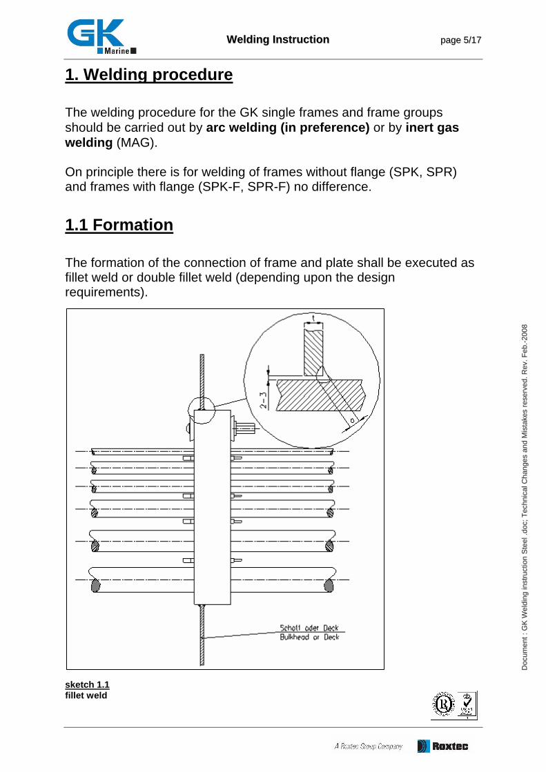
1.1 Formation The formation of the connection of frame and plate shall be executed as fillet weld or double fillet weld (depending upon the design requirements).
sketch 1.1 fillet weld
WWeellddiinngg IInnssttrruuccttiioonn ppaaggee 66//1177
DDoo cc
uu mmee nn
tt :: GG
KK WW
ee lldd ii
nn gg ii nn
ss ttrr uu
cc ttii oo
nn SS
tt eeee ll
.. ddoo cc
;; TTee cc
hh nnii cc
aa ll CC
hh aann gg
ee ss aa
nn dd MM
ii sstt aa
kk eess
rr eess ee
rr vvee dd
.. RRee vv
.. FFee bb
.. -- 2200 00
88
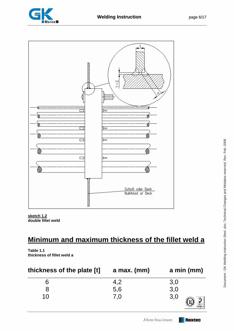
sketch 1.2 double fillet weld
Minimum and maximum thickness of the fillet weld a Table 1.1 thickness of fillet weld a
thickness of the plate [t] a max. (mm) a min (mm) _________________________________________________________________________________
6 4,2 3,0 8 5,6 3,0 10 7,0 3,0
WWeellddiinngg IInnssttrruuccttiioonn ppaaggee 77//1177
DDoo cc
uu mmee nn
tt :: GG
KK WW
ee lldd ii
nn gg ii nn
ss ttrr uu
cc ttii oo
nn SS
tt eeee ll
.. ddoo cc
;; TTee cc
hh nnii cc
aa ll CC
hh aann gg
ee ss aa
nn dd MM
ii sstt aa
kk eess
rr eess ee
rr vvee dd
.. RRee vv
.. FFee bb
.. -- 2200 00
88
1.2 Welding current The intensity of current is to be adjusted so that on the one hand sufficient fusing of the material is ensured, on the other hand the influx of heat is limited as far as possible in order to avoid thermal stress and distortion.
1.3 Welding material 1.3.1 Electrode
Naming of a suitable staff electrode: Type E 425 B 32 H5 *) DIN 1912 Explanation: E 42 5 B 3 2 H5 - H2 content 5ml/100g welding material - PA and PB welding position - type of current AC/DC - case: basic (reverse drying at 300°C; 2h) - minimum notch bar work: 47J at -50°C - tensile strength: Rm 420 N/mm2 - arc welding alternative Type E4343 RR (B) 7 *) DIN 1912 Explanation: E 43 4 3 RR(B)7 case: thick titan oxide basic minimum notch bar work: 47J at - 20°C minimum notch bar work: 28J at - 30°C tensile strength: Rm 4300 N/mm2 arc welding
WWeellddiinngg IInnssttrruuccttiioonn ppaaggee 88//1177
DDoo cc
uu mmee nn
tt :: GG
KK WW
ee lldd ii
nn gg ii nn
ss ttrr uu
cc ttii oo
nn SS
tt eeee ll
.. ddoo cc
;; TTee cc
hh nnii cc
aa ll CC
hh aann gg
ee ss aa
nn dd MM
ii sstt aa
kk eess
rr eess ee
rr vvee dd
.. RRee vv
.. FFee bb
.. -- 2200 00
88
1.3.2 Welding rod
Naming of a suitable welding rod (MAG method); 1) Type EMK 6D; 1,2 mm; material number: 1.5125 *) DIN 8559 SG 2 alternative 2) Type SG3 C Y46 4 3 *) Explanation: SG3 C Y46 4 3 minimum notch bar work: 47J at - 20°C minimum notch bar work: 28J at - 30°C RP= 460 N/mm2 Rm=530 - 680 N/mm2 inert gas CO2 mechanical quality grade 3 The thrust of the welding rod has to be adjusted as conditions demand.
1.3.3 Inert gases
Naming of a suitable inert gas (MAG) : Acc. to 1) M2.1 (Corgon 18) inert DIN 32526 - M21 *) Acc. to 2) C1 (Carbonic acid DIN 32526 - C1 *) The inert gas consumption is stated with 15l/min *) *) All stated data are to be understood as recommendations, which have to be checked in regard to their application in each single case by the company which executes the welding work.
WWeellddiinngg IInnssttrruuccttiioonn ppaaggee 99//1177
DDoo cc
uu mmee nn
tt :: GG
KK WW
ee lldd ii
nn gg ii nn
ss ttrr uu
cc ttii oo
nn SS
tt eeee ll
.. ddoo cc
;; TTee cc
hh nnii cc
aa ll CC
hh aann gg
ee ss aa
nn dd MM
ii sstt aa
kk eess
rr eess ee
rr vvee dd
.. RRee vv
.. FFee bb
.. -- 2200 00
88
2. Cut out
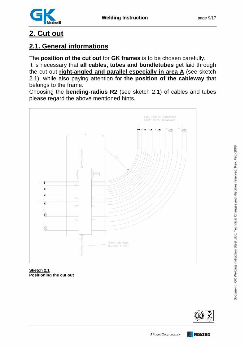
2.1. General informations The position of the cut out for GK frames is to be chosen carefully. It is necessary that all cables, tubes and bundletubes get laid through the cut out right-angled and parallel especially in area A (see sketch 2.1), while also paying attention for the position of the cableway that belongs to the frame. Choosing the bending-radius R2 (see sketch 2.1) of cables and tubes please regard the above mentioned hints.
Sketch 2.1 Positioning the cut out
WWeellddiinngg IInnssttrruuccttiioonn ppaaggee 1100//1177
DDoo cc
uu mmee nn
tt :: GG
KK WW
ee lldd ii
nn gg ii nn
ss ttrr uu
cc ttii oo
nn SS
tt eeee ll
.. ddoo cc
;; TTee cc
hh nnii cc
aa ll CC
hh aann gg
ee ss aa
nn dd MM
ii sstt aa
kk eess
rr eess ee
rr vvee dd
.. RRee vv
.. FFee bb
.. -- 2200 00
88
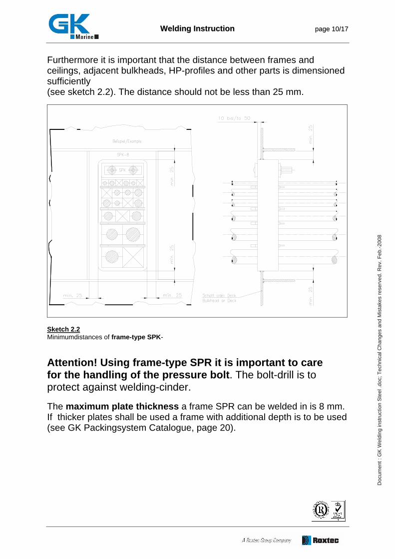
Furthermore it is important that the distance between frames and ceilings, adjacent bulkheads, HP-profiles and other parts is dimensioned sufficiently (see sketch 2.2). The distance should not be less than 25 mm.
Sketch 2.2 Minimumdistances of frame-type SPK-
Attention! Using frame-type SPR it is important to care for the handling of the pressure bolt. The bolt-drill is to protect against welding-cinder. The maximum plate thickness a frame SPR can be welded in is 8 mm. If thicker plates shall be used a frame with additional depth is to be used (see GK Packingsystem Catalogue, page 20).
WWeellddiinngg IInnssttrruuccttiioonn ppaaggee 1111//1177
DDoo cc
uu mmee nn
tt :: GG
KK WW
ee lldd ii
nn gg ii nn
ss ttrr uu
cc ttii oo
nn SS
tt eeee ll
.. ddoo cc
;; TTee cc
hh nnii cc
aa ll CC
hh aann gg
ee ss aa
nn dd MM
ii sstt aa
kk eess
rr eess ee
rr vvee dd
.. RRee vv
.. FFee bb
.. -- 2200 00
88
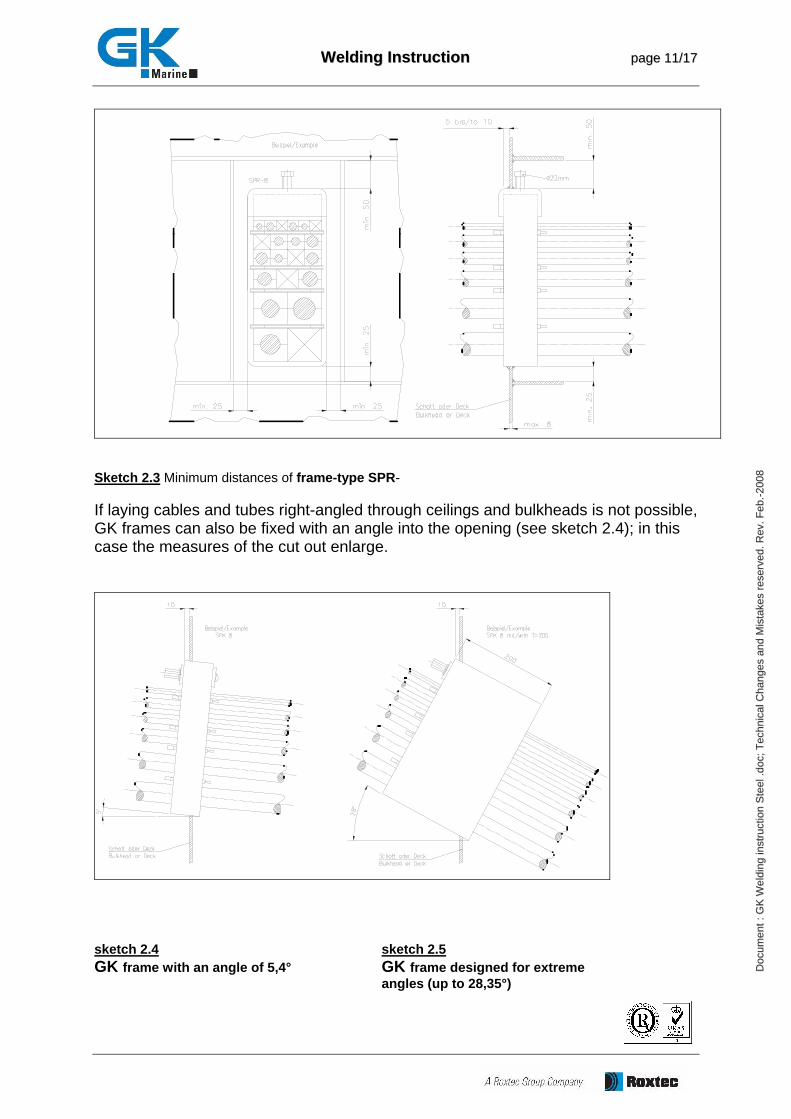
Sketch 2.3 Minimum distances of frame-type SPR- If laying cables and tubes right-angled through ceilings and bulkheads is not possible, GK frames can also be fixed with an angle into the opening (see sketch 2.4); in this case the measures of the cut out enlarge.
sketch 2.4 sketch 2.5 GK frame with an angle of 5,4° GK frame designed for extreme angles (up to 28,35°)
WWeellddiinngg IInnssttrruuccttiioonn ppaaggee 1122//1177
DDoo cc
uu mmee nn
tt :: GG
KK WW
ee lldd ii
nn gg ii nn
ss ttrr uu
cc ttii oo
nn SS
tt eeee ll
.. ddoo cc
;; TTee cc
hh nnii cc
aa ll CC
hh aann gg
ee ss aa
nn dd MM
ii sstt aa
kk eess
rr eess ee
rr vvee dd
.. RRee vv
.. FFee bb
.. -- 2200 00
88
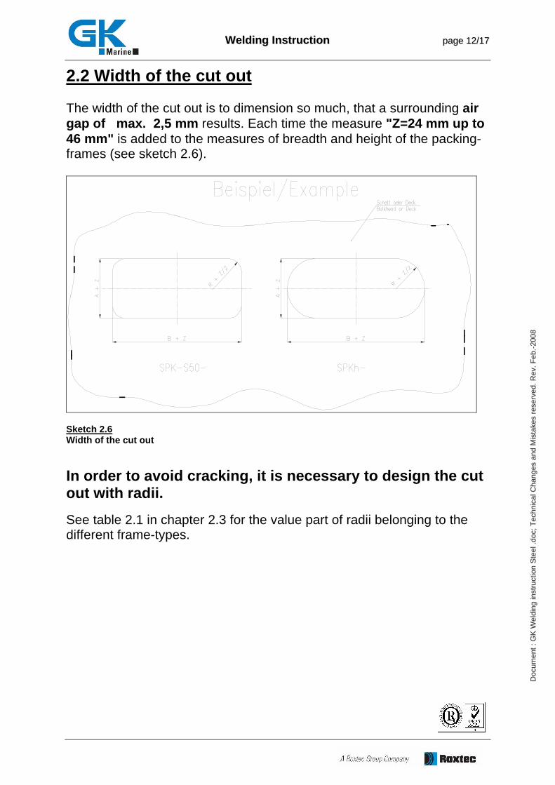
2.2 Width of the cut out The width of the cut out is to dimension so much, that a surrounding air gap of max. 2,5 mm results. Each time the measure "Z=24 mm up to 46 mm" is added to the measures of breadth and height of the packing-frames (see sketch 2.6).
Sketch 2.6 Width of the cut out
In order to avoid cracking, it is necessary to design the cut out with radii. See table 2.1 in chapter 2.3 for the value part of radii belonging to the different frame-types.
WWeellddiinngg IInnssttrruuccttiioonn ppaaggee 1133//1177
DDoo cc
uu mmee nn
tt :: GG
KK WW
ee lldd ii
nn gg ii nn
ss ttrr uu
cc ttii oo
nn SS
tt eeee ll
.. ddoo cc
;; TTee cc
hh nnii cc
aa ll CC
hh aann gg
ee ss aa
nn dd MM
ii sstt aa
kk eess
rr eess ee
rr vvee dd
.. RRee vv
.. FFee bb
.. -- 2200 00
88
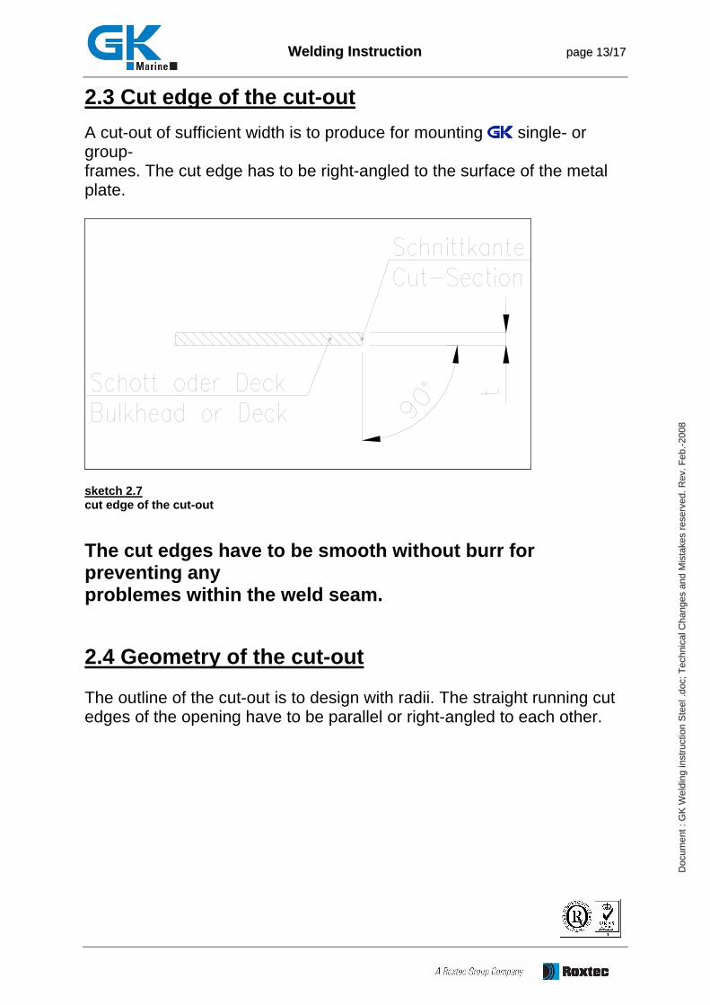
2.3 Cut edge of the cut-out A cut-out of sufficient width is to produce for mounting single- or group- frames. The cut edge has to be right-angled to the surface of the metal plate.
sketch 2.7 cut edge of the cut-out
The cut edges have to be smooth without burr for preventing any problemes within the weld seam. 2.4 Geometry of the cut-out The outline of the cut-out is to design with radii. The straight running cut edges of the opening have to be parallel or right-angled to each other.
WWeellddiinngg IInnssttrruuccttiioonn ppaaggee 1144//1177
DDoo cc
uu mmee nn
tt :: GG
KK WW
ee lldd ii
nn gg ii nn
ss ttrr uu
cc ttii oo
nn SS
tt eeee ll
.. ddoo cc
;; TTee cc
hh nnii cc
aa ll CC
hh aann gg
ee ss aa
nn dd MM
ii sstt aa
kk eess
rr eess ee
rr vvee dd
.. RRee vv
.. FFee bb
.. -- 2200 00
88
The most important frame-types and their radii GK Types SPK/SPR-60 Size 2 up to 8 R = 12 mm SPK/SPR Size 2 up to 8; Single- and groupframes R = 12 mm SPK-S30 Size 2 up to 8; Single- and groupframes R = 32 mm SPK-S50 Size 2 up to 8; Single- and groupframes R = 52 mm SPKh-120 Size 2 up to 8 R = 72 mm SPKh-180 Size 2 up to 8 R = 102 mm Table 2.1 Radii of the cut-out
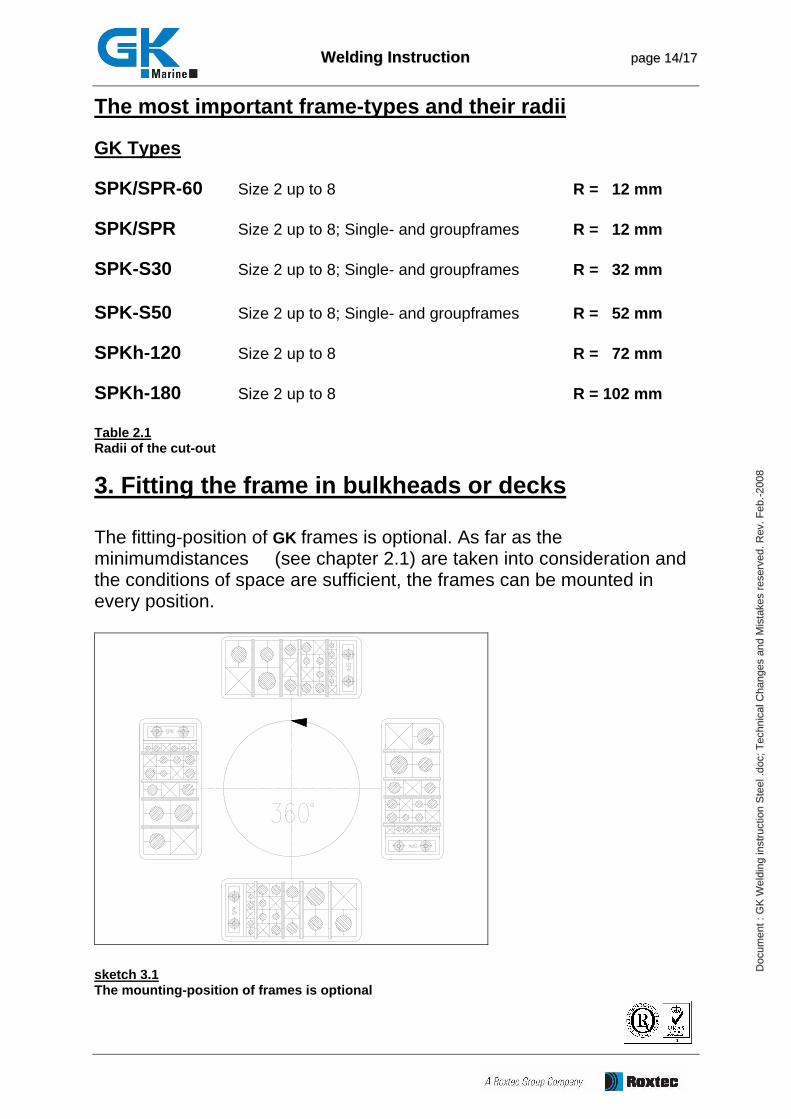
3. Fitting the frame in bulkheads or decks The fitting-position of GK frames is optional. As far as the minimumdistances (see chapter 2.1) are taken into consideration and the conditions of space are sufficient, the frames can be mounted in every position.
sketch 3.1 The mounting-position of frames is optional
WWeellddiinngg IInnssttrruuccttiioonn ppaaggee 1155//1177
DDoo cc
uu mmee nn
tt :: GG
KK WW
ee lldd ii
nn gg ii nn
ss ttrr uu
cc ttii oo
nn SS
tt eeee ll
.. ddoo cc
;; TTee cc
hh nnii cc
aa ll CC
hh aann gg
ee ss aa
nn dd MM
ii sstt aa
kk eess
rr eess ee
rr vvee dd
.. RRee vv
.. FFee bb
.. -- 2200 00
88
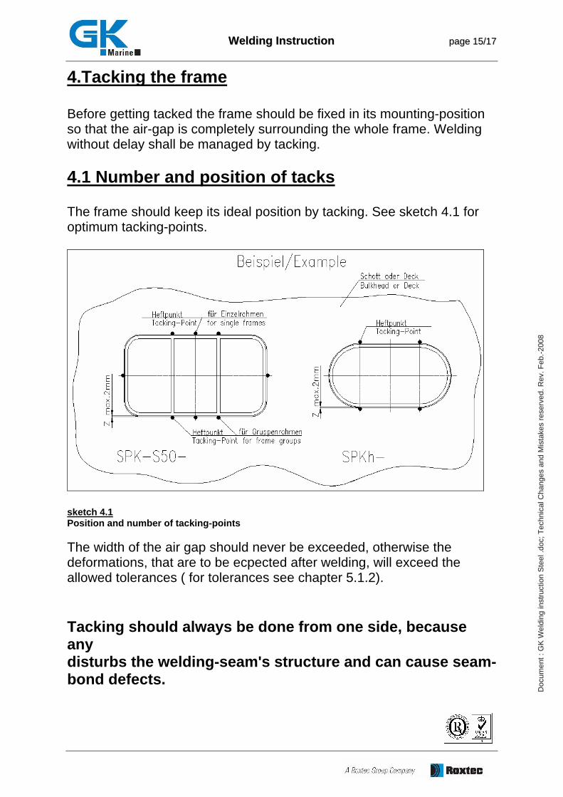
4.Tacking the frame Before getting tacked the frame should be fixed in its mounting-position so that the air-gap is completely surrounding the whole frame. Welding without delay shall be managed by tacking. 4.1 Number and position of tacks The frame should keep its ideal position by tacking. See sketch 4.1 for optimum tacking-points.
sketch 4.1 Position and number of tacking-points The width of the air gap should never be exceeded, otherwise the deformations, that are to be ecpected after welding, will exceed the allowed tolerances ( for tolerances see chapter 5.1.2).
Tacking should always be done from one side, because any tack disturbs the welding-seam's structure and can cause seam-bond defects.
WWeellddiinngg IInnssttrruuccttiioonn ppaaggee 1166//1177
DDoo cc
uu mmee nn
tt :: GG
KK WW
ee lldd ii
nn gg ii nn
ss ttrr uu
cc ttii oo
nn SS
tt eeee ll
.. ddoo cc
;; TTee cc
hh nnii cc
aa ll CC
hh aann gg
ee ss aa
nn dd MM
ii sstt aa
kk eess
rr eess ee
rr vvee dd
.. RRee vv
.. FFee bb
.. -- 2200 00
88
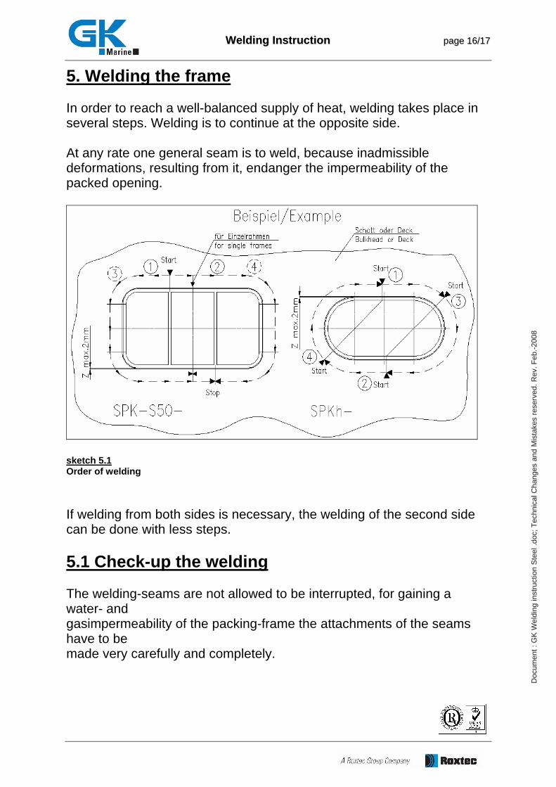
5. Welding the frame In order to reach a well-balanced supply of heat, welding takes place in several steps. Welding is to continue at the opposite side. At any rate one general seam is to weld, because inadmissible deformations, resulting from it, endanger the impermeability of the packed opening.
sketch 5.1 Order of welding If welding from both sides is necessary, the welding of the second side can be done with less steps. 5.1 Check-up the welding The welding-seams are not allowed to be interrupted, for gaining a water- and gasimpermeability of the packing-frame the attachments of the seams have to be made very carefully and completely.
WWeellddiinngg IInnssttrruuccttiioonn ppaaggee 1177//1177
DDoo cc
uu mmee nn
tt :: GG
KK WW
ee lldd ii
nn gg ii nn
ss ttrr uu
cc ttii oo
nn SS
tt eeee ll
.. ddoo cc
;; TTee cc
hh nnii cc
aa ll CC
hh aann gg
ee ss aa
nn dd MM
ii sstt aa
kk eess
rr eess ee
rr vvee dd
.. RRee vv
.. FFee bb
.. -- 2200 00
88
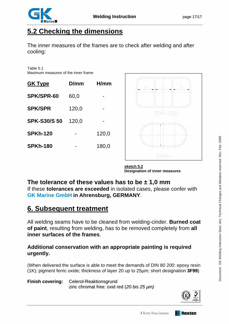
5.2 Checking the dimensions The inner measures of the frames are to check after welding and after cooling: Table 5.1 Maximum measures of the inner frame GK Type D/mm H/mm SPK/SPR-60 60,0 - SPK/SPR 120,0 - SPK-S30/S 50 120,0 - SPKh-120 - 120,0 SPKh-180 - 180,0 sketch 5.2 Designation of inner measures The tolerance of these values has to be ± 1,0 mm If these tolerances are exceeded in isolated cases, please confer with GK Marine GmbH in Ahrensburg, GERMANY. 6. Subsequent treatment All welding seams have to be cleaned from welding-cinder. Burned coat of paint, resulting from welding, has to be removed completely from all inner surfaces of the frames. Additional conservation with an appropriate painting is required urgently. (When delivered the surface is able to meet the demands of DIN 80 200: epoxy resin (1K); pigment ferric oxide; thickness of layer 20 up to 25µm; short designation 33FF9999)) FFiinniisshh ccoovveerriinngg:: CCeelleerrooll--RReeaakkttiioonnssggrruunndd
zziinncc cchhrroommaatt ffrreeee:: ooxxiidd rreedd ((2200 bbiiss 2255 µµmm))