Embed Size (px)
Citation preview
भारत सरकार Government of India
अत र वभाग Department of Space
इसरो जड़ वीय णाल य नटISRO Inertial Systems Unit
व यरकाव Vattiyoorkavu
त वनतपरम Thiruvananthapuram ndash 695 013
व ापन सआईआईएसयपीट व ापन 022015 दनाक 22052015 ADVTNOIISUPTADVT-022014 dated 22052015
भारत क रा प त क लए तथा उनक ओर स व र ठ य एव भडार अ धकार इसरो जड वीय णाल य नट (आई आई एस य) व यरकाव पी ओ त वनतपरम मोहरबद न वदाए आम त करत ह -
For amp on behalf of the President of India the Sr Purchase amp Stores Officer ISRO Inertial
Systems Unit (IISU) Vattiyoorkavu Thiruvananthapuram invites Sealed Tenders for the following items-
म स Sl No
न वदा स Tender No
ववरणDescription मा ा Qty
01 8301-2014007870 Space Qualified Absolute Rotary Inductosyn 12 Nos
02 8301-2015000061 Absolute Rotary Inductosyn and Processing Electronics 2 Nos 03 8234-2014008481 3 Axis Angular Motion Simulator 1 System 04 8234-2014008487 Gyrotheodolite 1 Set 05 8504-2015000568 High Precision Vertical Machining Centre 1 No 06 8504-2015000569 High Precision CNC EDM Machine 1 No 07 8222-2015000435 3D Optical Profilometer 1 No 08 8211-2014007990 Supply Installation testing and commissioning of 500 kVA
Acoustic Diesel Generator Set 1 Set
All the above cases are TWO ndashPART TENDER basis Part-1 (Technicalamp Commercial) Part-2 (Price Bid)
उपरो त सभी मामल दो भाग वाल न वदाए ह ndash भाग-1 (तक नक तथा वा णि यक) भाग-2 (म य बोल )
न वदा श क Tender Fee Rs 227-
न वदा फाम जार करन क अ तम त थ Last Date for issue of Tender Forms
24062015 1600 बज तक up to 1600 Hrs
न वदा वीक त क लए नयत त थ Due Date for Receipt of Tender
25062015 1600 बज तक up to 1600 Hrs
न वदा खोलन क त थ Tender Opening Date
26062015 1000 बज at 1000 Hrs
इसरो वब साईट wwwisrogovin म न वदा द तावज़ उपल ध ह I इ छक न वदाकता न वदा अ धसचना म दए गए ववरण क अनसार इस वब साईट स न वदा द तावज़ डाउनलोड कर और व र ठ लखा अ धकार आइआइएसय लखा व टटयरकाव पीओ त वनतपरम - 695013 क नाम पर भारतीय टट बक म य शाखा ट य त वनतपरम पर दय र खत डमाड ा ट क प म नधा रत न वदा लागत क साथ अपना ताव तत कर
Tender documents are available on ISRO web site wwwisrogovin Interested tenderers may download the tender documents from the web site and submit their offers alongwith the prescribed tender cost in the form of CROSSED DEMAND DRAFT drawn in favour of Sr Accounts Officer IISU Accounts Vattiyoorkavu PO Thiruvnanthapuram-695013 payable at State Bank of India Main Branch Statue Thiruvananthapuram as per details given in the Tender Notification
ह ता रतSd-
व र ठ य एव भडार अ धकार Sr Purchase amp Stores Officer
TENDER NO8301-2014007870
Space Qualified Absolute Rotary Inductosyn
10 Introduction A high accuracy (3 arc seconds) absolute rotary inductosyn is planned to be used as the position sensor in scan mechanism for sounder amp imager payload in INSAT 3DR GSAT mission for meteorological application The scan mechanism has two modes-slow scan and fast scan The function of scan mechanism is to provide two DOF movements to the optical mirror and to cater to the scan rate need to accurately control in closed loop
The specification test plan quality assurance amp reliability models amp quantity required and documents required are mentioned in this RFP document
20 General Specification
The general specifications include type size mass mechanical amp electrical interface position resolution operating speed environmental test levels radiation levels etc The following table provides the general specification
Sl No Parameters Specification Comments
1 Type Absolute rotary inductosyn without bearing amp slip ring
a Stator and rotor independent modules
b Inside rotor (hollow) configuration
2 Inner diameter ID 20 mm - 3 Outer diameter OD 160 mm - 4 Height 35 mm (max) - 5 Accuracy +- 3 arc second - 6 Partial Rotation 0-170 degree - 7 Operating speed +- 100 degsec - 8 Acceleration 60 ˚s2 -
9 Voltage Transformation Ratio
20 at 10 KHz Operating frequency Range 200 Hz- 200 KHz
10 Qualification temp -20 deg to +80 deg -
11 Humidity 95 -
12 Qualification pressure level 1 x 10⁻⁶ torr or better Compatible for air (ambient)
and vacuum operation
13 Qualification vibration level
Random25grms (Duration 2 min) Sine 5-20 Hz 22mm DA 20-100 Hz 20g Sweep rate 2 octmin
-
14 EMI level As per MIL ndash STD 461C and 462 -
15 Radiation level 100 Krad Total dose
16 Substrate material Titanium -
17 Flexible cables Rotor connection with flexible cables -
18 Lead wire AWG silver plated copper wire as per MIL-W-22759 (desirable)
The lead wires should be terminated in a connector or turret
Model Philosophy
301 Qualification Model (QM)- 2 numbers
The QM model shall meet the specifications indicated in the qualification tests and is identical to the flight model The criteria for the completion of the qualification are that the unit shall successfully undergo the qualification tests After the qualification this unit shall be delivered to ISRO
302 Flight Models (FM)-10 numbers
These units which are to be used in FM mechanisms shall undergo acceptance tests
40 Quality Provisions amp Environmental specifications
401 Quality assurance provisions
The QA provisions consists of
Material selection and acceptance for use in space Process control and quality control requirements Acceptance test plan generation and qualification of the product Acceptance test plan for the product Non-conformance management and control
These shall commensurate with the requirements of satisfactory operation during the entire life span of 12 years in geostationary orbit environment after storage up to five years on ground 402 Absolute maximum environmental conditionslife
The flight worthy products for supply to ISRO must be subjected to only acceptance level environmental conditions The rotary inductosyn transducer shall be capable of operation without any degradation in performance after storage for a period of 12 years on ground [The design life of the products must be 15 years in orbital environment] The manufacturer shall give the nature of degradation after five years and ten years of shelf life and its impact on orbital life Procedures for refurbishment the requirements on storage environment etc must be provided to ISRO by the manufacturer
403 Process The unit shall be built to standards normally associated with long life spacecraft hardware Particular attention must be paid to cleanliness thoroughness of plating coating bonding sealing etc all tolerances not specified shall be as per best engineering practice The product must be uniform in quality and free from defects The witness coupon of the stator and rotor discs shall withstand the standard adhesion and tape test 404 Marking amp traceability Each product shall be identified by unique serial number on the visible surface by a suitable process applicable for space use Marking shall not degrade the performance of the unit and this marking shall ensure the traceability in respect of the material process and year of manufacture The markings shall withstand the test environments cleaning process etc without any degradation Each product shall have 1Part number 2Serial number
405 Acceptance tests The flight worthy products must be subjected to acceptance level tests All products supplied to ISRO must be accompanied by QC certificate clearly indicating the test done and results and a certificate of compliance to the quality control plan 406 Test plan amp test specification The test sequence as given in the document shall be adhered to No additions deletions or alternations shall be done to test sequences or test specifications without prior approval in writing from ISRO The manufacturer shall be responsible for the performance test setupsequipments required to demonstrate the applicable specifications The manufacturer shall submit the test plan for the performance and environmental tests to be conducted on Inductosyn during qualification and acceptance test program The test plan shall include the procedure for conducting each test the test equipments used and their calibration and individual parameter limits The test plan shall include at least the following in sequence indicated below Sl No Tests Qualification Model Flight Model
1 Visual Inspection amp Physical Measurements
2 Reference Performance
3 Burn-in-test X
4 Sine Vibration X
5 Random Vibration (Qualification level) (Acceptance level)
6 Thermal Vacuum Cycling (Qualification level) (Acceptance level)
7 Final Performance
4061 Visual inspectionmechanical dimension checks
a) The lead wires must be inspected for cut cracked insulation color etc The insulation resistance between leads and the body must be recorded
b) Mating surfaces must be inspected for burr upsets rust scale formation or any other defect which may lead to improper alignment
c) Inspect the name label serial number and the reference mark on the stator and rotor d) The stator ID OD stator height rotor OD shaft hole dia mounting hole dia mounting hole
position weight etc must be measured and its compliance checked and recorded with reference to our drawing
4062 Environmental tests
The rotary inductosyn transducer asked for must have the capability to withstand the following test environments
40621 Thermal cycling test
Five short cycles of cold [-20˚C for 2 hrs] and hot [80˚C for 2hrs] and one long cycle of cold [-20˚C for 6 hrs] and hot [80˚C for 6 hrs] with a transition rate 5˚Cmin Condition of unit under test active
40622 Thermal vacuum test
The inductosyn shall endure the following qualification and acceptance level testing
Description Acceptance level Qualification level
Hot exposure temperature
+650C +20C for 24 hours duration +800C +20C for 24 hours duration
Pressure 1 x 10⁻⁶ torr or better 1 x 10⁻⁶ torr or better
Cold exposure temperature
-100C +20C for 24 hours duration -200C +20C for 24 hours duration
Pressure 1 x 10⁻⁶ torr or better 1 x 10⁻⁶ torr or better
Condition of unit under test active
40623 Vibration tests
Sine vibrations
The inductosyn may endure sinusoidal vibrations in X Y and Z axes
Random vibrations
The inductosyn may endure random vibrations in X Y and Z axes Test Qualification level Acceptance level
20-100 Hz + 3 dBoct + 3 dB oct
100-700 Hz 0451 g2 Hz 0199 g2 Hz
700-2000 Hz - 3 dBoct - 3 dBoct
Overall grms 250 166
Duration 2 min per axis 1 min per axis
Condition of unit under test non-operating during the test
Frequency in Hz Amplitude
5-20 22 mm DA
20-100 20 g
Sweep rate 2 octaves minute
The system shall be visually inspected after each of the above vibration tests and performance evaluated after completion of the above tests
40624 Storage
-40˚C for minimum 24 hrs duration +100˚C for minimum 24 hrs duration Condition of unit under test non-operating during test 40625 Final performance test
Complete functional test shall be carried out after thermovaccum test
50 Packing
The inductosyn units shall be placed inside a sealed metallic container that will be filled
with dry nitrogen An integrated dial manometer in the container allows to check the
internal pressure that shall be 15 bar (nominal value)
The two sub-assemblies (Stator amp Rotor) shall be fixed inside a same transportation container This container shall be packed into a sealed plastic bag with silica moisture absorbents this bag packed into transport container This global packaging will protect the inductosyn for all kinds of usual ways (air sea ground) A shock detector shall be installed on both the containers The transportation package shall protect the encoder assembly from the rough handling test specified in MIL-P-116
60 Documents required
601 Documents required along with the quotation Overall specification interface drawings electrical interface details proposed tests amp test procedure document
602 Documents to be supplied after order placement
6021 Technical specification and Design document
6022 Product assurance plan detailing the aspects of
Fabrication and process control
Inspection and acceptance criteria to be followed
FMECA and reliability analysis
Non-conformance control
Configuration control and traceability
Derating Analysis
6023 Test procedure document (update) The detailed test and evaluation procedure and programmes for qualification and acceptance tests shall be subjected for approval by ISRO before the test is performed The test procedures shall contain the following-
a All the activities described in steps right from the start to the end of the test including
handling inspection pre and post functional tests along with the time schedule
b Description of the test procedure test facility environmental conditions calibration
and operational details
c Format of test results required during testing giving specified values and tolerances
d Failure criteria test termination retest and test sequence and damage limits
e List of equipment needed for functional test and full performance test
6024 Drawings and Layouts
Electrical and mechanical interface drawings and layout shall be provided together with component list critical spare part list along with the vendorrsquos address and component code numbers if any
603 Documents to be supplied along with the hardware
The supplier shall deliver an Acceptance Data Package (ADP) containing the following documents
6031 Technical Specification (update)
6032 Final Test Reports A final report indicating the functional performance of inductosyn before and after qualification acceptance tests should be provided The deviations observed during qualification acceptance and reports on visual inspection giving consolidated data shall be made available
6033 Anomaly Reports Reports for malfunction deviation in operation from the specifications shall be made available along with the corrective actions taken to meet the specifications
6034 User Manual Handling transport and storage conditions shall be handed over along with the unit along with a certificate of conformance to the specifications
Tender no8301-2015000061
Absolute Rotary Inductosyn and Processing Electronics The specifications quantity required and documents required are mentioned in this RFP document
10 General Specification The general specifications include type size mass mechanical amp electrical interface position resolution operating speed The following table provides the general specification
20 Model Philosophy
Engineering Model (EM) and processing electronics (2 numbers) ndash This shall be commercial grade absolute rotary inductosyn along with its processing electronics
30 Marking amp traceability
Marking shall not degrade the performance of the unit and this marking shall ensure the traceability in respect of the material process and year of manufacture The markings shall withstand cleaning process without any degradation Each product shall have 1Part number 2Serial number
Sl No
Parameters Specification Comments
1 Type Absolute rotary inductosyn without bearing amp slip ring
c Stator and rotor independent modules
d Inside rotor (hollow) configuration
2 Inner diameter ID 20 mm -
3 Outer diameter OD 160 mm - 4 Height 35 mm (max) - 5 Accuracy +- 3 arc second - 6 Partial Rotation 0-170 degree - 7 Operating speed +- 100 degsec - 8 Acceleration 60 ˚s2 - 9 Voltage
Transformation Ratio 20 at 10 KHz Operating frequency Range 200
Hz- 200 KHz 10 Substrate material Titanium -
11 Flexible cables Rotor connection with flexible cables - 12 Lead wire The lead wires should be
terminated in a connector or turret
13 Position resolution 19 bit -
14 Input Output interface
Standard RS-422-Adigital -
15 Direction of rotation Binary code increasing in clockwise rotation looking from inductosyn electronics side
-
16 Operating supply voltage
+5V plusmn15V -
40 Packing
The inductosyn units shall be placed inside a sealed metallic container that will be filled with dry nitrogen An integrated dial manometer in the container allows to check the internal pressure that shall be 15 bar (nominal value)
The two sub-assemblies (Stator amp Rotor) shall be fixed inside a same transportation container This container shall be packed into a sealed plastic bag with silica moisture absorbents this bag packed into transport container This global packaging will protect the inductosyn for all kinds of usual ways (air sea ground) A shock detector shall be installed on both the containers
50 Documents required
501 Documents required along with the quotation
Overall specification interface drawings electrical interface details document
502 Documents to be supplied after order placement 5021 Technical specification and Design document
Configuration control and traceability
5022 Drawings and Layouts
Electrical and mechanical interface drawings and layout shall be provided together with component list critical spare part list along with the vendorrsquos address and component code numbers if any
5023 Technical Specification (update)
5024 User Manual
Handling transport and storage conditions shall be handed over along with the unit along with a certificate of conformance to the specifications
60 Visual inspectionmechanical dimension checks
a) The lead wires must be inspected for cut cracked insulation color etc The insulation resistance between leads and the body must be recorded
b) Mating surfaces must be inspected for burr upsets rust scale formation or any other defect which may lead to improper alignment
c) Inspect the name label serial number and the reference mark on the stator and rotor d) The stator ID OD stator height rotor OD shaft hole dia mounting hole dia mounting
hole position weight etc must be measured and its compliance checked and recorded with reference to our drawing
Tender No 8234 -2014 00 8481
Request for Proposal for 3-Axis Angular Motion Simulator
10 Introduction This document describes the system configuration and required performance characteristics of the electronic and mechanical subsystems and the computer interface requirements of a 3-Axis Angular Motion Simulator
Basically the system comprises of a 3-Axis table power amplifier and a controller
The system shall be capable of
Operation from the control console Remotely from a digital computer Accept analog signals in external mode
In any mode the system should be capable of being commanded in position control mode angular velocity mode and synthesis mode It should be possible to command these modes for all the three gimbals
The controller must provide a flexible and user-friendly environment for the control of the table by way of data entry display and monitoring
It should be possible to make data entries in local mode through touch screen
In remote mode it should be controlled by an external digital computer through built-in computer interface module
Built in diagnostics data logging capability and servo debug tools shall be provided to ascertain system health prior to its utilization The controller must provide features for easy fault diagnosis of the total system
Quantity 1 System
20 System Configuration
21 General
The 3-Axis Angular Motion Simulator must have three gimbalsaxis designated as inner middle and outer The three axes shall be mutually orthogonal intersecting at a common point The outer axis shall be vertical middle axis horizontal and inner axis orthogonal to middle axis The outer gimbal is of open frame design and the middle and the inner gimbals are of closed frame type with two platens with necessary tapped holes with threaded inserts for mounting the unit under test (UUT) The hole pattern shall be customer specified hole pattern with solid thread inserts with locking keys In addition tapped holes with threaded inserts must be provided at suitable locations on the inner gimbal frame for anchoring of the cables running between the two platens
Each gimbal shall be capable of full angular freedom around its support axis and each axis shall be supported on anti friction bearings The outer axis bearing and drive system shall be housed in a suitable base to permit rigid attachment of the system to the foundation A base template along with six point mounting arrangement with precision leveling wedges to permit horizontal alignment of the system must be provided Suitable provision shall be made for precision azimuth adjustment 22 Servo components The drive for each axis shall be direct drive torquers Each axis must incorporate an Inductosyn Resolver position transducer package directly mounted to the axis shaft and have absolute position encoding Each axis shall have a manual clamp with vernier adjustment knob
23 Static Balancing
Necessary provision shall be incorporated for attaching suitable counter weights to the table top and middle axis for static balancing of the two axis for different size and weight of the payload Suitable counter weights shall be provided for balancing inner and middle axis
24 Table Top
The table top of the inner axis assembly shall interface with the UUT Suitable MIL standard connectors mounted at the periphery of the table top shall permit electrical access to UUT Two sets of mating connectors suitable for both table top and table base connectors must be provided
The design of the table top attachment to the gimbal should be such that no change takes place in level and azimuth due to repeated dismounting and mounting of the table top Suitable locating pins (Dowel pins) must also be provided for retaining the established angular position Removing the table top must not disturb level and azimuth alignment
The material used for the lower table top must be Titanium alloy Ti6Al4V annealed condition which maintains the level on its entire surface within 10 arc sec or better over a period of time The flatness of the table top must be 30 microns or better for the entire area of the tabletop The material used must be corrosion resistant dimensionally stable and stiff
The material used for the upper table top must be hard Anodised aluminium alloy Type PERALUMANndash460 EN AW-5083 which maintains the level on its entire surface within 10 arc sec or better over a period of time The flatness of the table top must be 30 microns or better for the entire area of the tabletop The material used must be corrosion resistant dimensionally stable and stiffCustomer specified hole pattern equipped with solid thread inserts with locking keys must be provided for which detailed drawing will be provided by the user at a later date The hole patterns needed for adapter plates for checkoutcalibration must also be taken care of
25 Electrical Access Slip Rings
Slip ring capsules in all the three axes must be provided for electrical access of the UUT as per the details furnished under system specifications The wiring schematic of the user slip rings must be furnished in the instruction manual Construction of the machine should be such that slip rings of each axis is accessible for maintenance without complete tear down to avoid recalibration of the system The slip ring make offered must be of proven make type especially with regard to specifications like insulation resistance noise cross talk life etc
26 Test Payload
A standard test inertia (of 140 Kgm2 about inner axis and 375 Kgm2 about middle axis) package must be delivered which will be used to verify the system performance periodically and for calibration of the system
27 Reference level surface
Necessary reference level surface must be provided on the middle amp outer gimbal to check the level of the table after installation and for periodic verification
28 Alignment
Necessary adapter sets to attach alignment mirrors cubes polygons shall be provided to conduct necessary system alignmentaccuracy tests calibration tests and payload alignment with respect to gimbal axes
29 Mounting Holes on Outer gimbal
Mounting holes (4 numbers square pattern) should be provided on both sides of outer gimbal (bottom) for fixing of reflecting mirror later (As per drawing to be given) 210 Thermal Management
Necessary forced air-cooling must be provided in order to avoid any hot spots in the sub systems namely controller Power amplifiers etc 211 Spares
The details of essential spares like Power Supplies Power Amplifiers Filters Controller Cards Fuses Limit Switches Controller Mother Board GUI Console etc must be listed and quoted as an option
System Specifications
310 General
311 Payload
a Package envelope 700mm cube
b Platen size 600mm diameter for lower table top
740mm diameter for upper table top
Distance between the table tops 710 mm
Note Detailed drawing to be submitted to the user for approval and any change in size hole pattern and any cut outs required to be confirmed before releasing for production
c Package weight
Nominal 60 Kg
Maximum 100 Kg
312 User Slip Ring and Electrical access to UUT a Mechanical
i 9 pairs of 5A twisted and shielded (pair wise) individually ii 50 pairs of 2A twisted and shielded (pair wise) individually iii 10 lines of 2A individually shielded iv Six lines as per MIL standard 1553
Note The slip ring wiring drawing including the spare rings to be submitted to the user for approval and any small changes as may be required to be incorporated before releasing for production
b Electrical
i Noise lt10 m V A per circuit at a rate 10 deg Sec
ii Insulation gt500 Megohms 250 V DC
Between any slip ring and chassis
Between any two slip rings
The best possible slip rings are to be used so as to achieve a value of lt10mVA per circuit at a rate of 10 degsec for the slip ring noise specification
31 Dimension
The detailed dimensions along with mass of the 3-axis table control console and power amplifier rack must be furnished in the instruction manual and supported by all mechanical drawings
313 Mechanical axes specifications
a Angular freedom continuous for all the three axis
b Wobble less than 2 arc sec for all the three axis
c Orthogonality
c1 Between Inner amp Middle axis lt 3 arc sec
c2 Between Middle amp Outer axis lt3 arc sec
d Gimbal Structure
d1 Inner Closed gimbal with two platens
d2 Middle Closed gimbal
d3 Outer Open gimbal
320 System performance specifications
SlNo
Parameter
Unit
Specification
Inner axis Middle axis Outer axis
1
2
3
4 5 6 7 8 9
10
11
12
Position Accuracy
Position range
Maximum rate
Maximum acceleration Rate accuracy averaged over 360 deg entire rate range Rate stability averaged over 360 deg entire rate range Composite Rate accuracy amp stability averaged over 10 deg 5 to 10 degsec range Composite Rate accuracy amp stability averaged over 1 deg 01 to 5 degsec range Position Resolution Rate Resolution Small signal Band width Flatness of frequency response in the pass band
arcsec RSS deg
degsec
degsec2
ppm
ppm
ppm
ppm
deg
degsec
Hz
1 0 to 35999999
500
1200 14
Kgm2 Better than 10
(0001)
lt1 (00001)
lt25
(00025)
lt150 (0015)
000001
00001
50 140 Kgm2
05dB up to 10 Hz 1dB over the rest$
1 0 to 35999999
300
600 375
Kgm2 Better than 10
(0001)
lt1 (00001)
lt25
(00025)
lt150 (0015)
000001
00001
20 375 Kgm2
05dB up to 10 Hz 1dB over the rest$
1 0 to 35999999
200
150
Better than 10
(0001)
lt1 (00001)
lt25
(00025)
lt150 (0015)
000001
00001
20
05dB up to 10 Hz 1dB over the rest$
The following points may be noted-
a The small signal bandwidth figures given are on the basis of ndash3dB gain or ndash90 deg phase lag lsquoWhichever occurs earlierrsquo
b The torque motors must be sized to give problem free operation within the specified dynamic range It is expected that the system when exercised to verify the small signal bandwidth will operate flawlessly over sustained periods without motor over temperature trip Motor type - Direct drive BLDC or Permanent Magnet AC
Frequency response$-
Necessary servo settingsadjustments shall be made to ensure that the response is as flat as possible in the pass band (not exceeding plusmn 05 dB up to 10 Hz and plusmn 1 dB over the rest of the range)
c The lowest integrated mechanical resonance frequency of the system should be as high as possible so that it does not constrain the dynamic response
d All efforts must be made to achieve the best possible figures for composite
rate stability amp accuracy (for all axes) FAT shall include demonstration of the required servo settings to achieve this specification
30 Controller Operating modes
The following shall be provided
41 Position Mode
For moving to a fixed position the system must take the shortest route to the new position The system must accelerate to a constant rate and decelerate to the commanded position without any overshoot The rate and acceleration must be Programmable
Data entry shall be either manual or in local mode or by computer via selected interface
Rate and acceleration must be contained to programmable limits so that smooth motion trajectories are maintained
42 Precision Rate Mode This mode is for moving at a constant rate Acceleration to the commanded rate is to be controlled Here the system must accelerate at a constant acceleration until the commanded rate is achieved Rate entry shall be through manual touch panel or from data bus The actual rate must not overshoot the commanded rate It should be possible to set the acceleration limit to within the dynamic range of the axis
43 Synthesis Mode (for sinusoidal motion)
The axis oscillates at a commanded amplitude and frequency Frequency and amplitude to be commanded via touch panel or from data bus
44 Track Mode
It should be possible to track an arbitrary motion profile commanded by an analog signal or through a digital interface When commanded through a digital interface the remote computer outputs a sampled data series of motion state vectors (eg- position rate and acceleration)
45 Analog command
The analog input ports on the IO panel must be enabled for position or for rate control from a function generator or other analog source
Position and rate scale factors must be programmable so that analog input range can correspond to any desired full-scale range
50 Data readout
51 Absolute position readout system
Outputs from the position transducer must be accessible either at touch panel display or by a computer via a standard bus interface The output display must include absolute angles in degrees and the rate at any instant
52 Analog outputs
It should be possible to view the internal variables as analog outputs on an oscilloscoperecorder All output ranging and scaling must be under operator control The list of variables available for monitoring must be furnished Two analog outputs per axis (total 6 nos) shall be provided
53 Event pulses
A termination must be provided for monitoring of the event pulses which are position dependent TTL pulses triggered at equally spaced positions over the full range of the motion travel It should be possible to select the number of pulses per revolution Each axis shall have independent event pulse output
60 Computer interfaces
It should be possible to control the system through a computer interface All the functional modes must be available to the system user in the computer mode through a computer interface module It must have a capability to connect a host computer through the following interfaces-
a General Purpose Interface Bus - IEEE 4882 b LAN interface (TCPIP) c Serial Port - RS 232 d Real Time Interface ndash SCRAMNET
70 Servo loops
The Servo loops should be software configurable for easy adaptation for varying test loads in position and rate modes The servo gaincompensation adjustments due to inertia variation through software are very important requirements for operational convenience and trouble free operation and must be provided as a standard feature The gimbals should be designed for high torsional stiffness
80 Safety provisions and Interlocks
The following safety provisions and interlocks must be provided
81 Rate trip
These are self-latching interlocks which disconnect power to the motors when the pre-selected rate is exceeded in any mode of operation This shall be possible through settings in the console through software Each axis shall have independent setting
82 Manual clamps
The system shall be provided with manual clamp with fine adjustment knob on each gimbal to enable the respective gimbals to be clamped manually at any angular position rigidly and provide fine adjustment capability In this case interlock switches shall be provided for each gimbal to prevent energizing the torquer motor on a particular gimbal when the gimbal is clamped
83 Stow locks
Each axis shall be provided with manually operated stow lock Inner and Outer axis shall be lockable in one position where as Middle axis shall be lockable in four positions (2 vertical and 2 horizontal) The servo operation must be inhibited if the stow lock is engaged
84 Rate limits
Necessary rate clamps shall be provided in each axis of the system for the safety of the UUT in every mode of operation When the commanded rate exceeds the set rate limit value the system must clamp to the set value of rate This shall be possible through settings in the console through software Each mode of operation shall have independent setting
85 Position limiting provision
Necessary provision shall be made to limit the gimbal positions independently for each gimbal over the entire dynamic range This shall be possible through settings in the console through software
86 Emergency off
A disable button must be provided on the front panel of controller to stop all motion and shut down the drives as a safety feature
87 Temperature
Torque motor temperature monitoring and interlock must be provided In the event of a fault the respective amplifier must shut down
88 User Disable Jumper
A jumper shall be provided when opened all the axis has to come to rest with preprogrammed deceleration and then the power to the drives shall be removed
90 Installation and other requirements
91 The table should have marking such as lsquoCErsquo
92 System Power requirements
a Power amplifier 400V three phase 50 Hz
(supply 3 lines neutral and separate ground) b Controller 230V single phase 50 Hz
Note Voltage tolerance plusmn 10
93 Foundation
The foundation details duly supported by necessary calculations must be submitted along with the offer
94 Pre-shipment inspection testing and training
Pre-shipment inspection and testing of the systems shall be conducted in the presence of customer at manufacturerrsquos facilities to verify all the system specifications in full system configuration Slip ring insulation measurements shall also form part of the pre-shipment inspection and testing The manufacturer shall prepare an acceptance test plan and procedure which shall address comprehensively to all aspects including a time table and the number of working days and have it reviewed and approved by the customer Testing shall include verification of performance over sustained periods Spares supplied along with the system shall be tested for functionality by substituting into the system Training shall be imparted to the customerrsquos representatives
95 Installation commissioning and acceptance testing at customerrsquos site
The manufacturer must install and commission the systems at customerrsquos site Acceptance test shall be carried out after installation to demonstrate the system performance and shall be as comprehensive as the FAT The customer acceptance testing must include critical test like Position accuracy wobble orthogonality etc Any impracticability in this regard must be specifically addressed and agreed by the customer Detailed acceptance test plan and procedure to be submitted to the customer well in advance
96 Documentation
The documentation shall include system parameters and ratings including maximum torque value for continuous operation of the three axes mechanical configuration drawings electrical schematics circuit diagrams interconnection diagrams operational manuals service cum troubleshooting manuals part list software manuals procedure for transducer calibration calibration and acceptance test procedures and results The instruction manual technical details and manufacturerrsquos certificate of brought out items like power amplifier motor and slip ring must also be supplied All documents shall be in English and supplied to the customer in duplicate
97 Warranty
All items shall be under warranty for a period of at least one year from the date of successful installation and commissioning at customerrsquos site Service support and availability of the spares must be ensured even after the expiry of the warranty for a period of at least 10 years
All hardwaresoftware updates on controller that are brought out during the warranty period shall be installed in the system free of charge together with the necessary documentation
98 Insurance
Warehouse to warehouse transit insurance to be borne by the supplier
100 Submission of Technical and Commercial price bids
This is a two part tender enquiry The quotations are invited in two parts in separate sealed covers
Part 1 - This sealed cover shall contain technical details covering all the technical aspects with necessary technical attachments literature supporting documents catalogues data sheets compliance statements of each point of the RFP commercial terms and conditions but without prices The quote shall contain the detailed information about the supply of similar systems to other customers preferably in India including the specifications and results obtained with documentary support
Part 2 - This sealed cover shall contain only the commercial bid with prices
Tender No8234-2014008487
Specifications for Gyro-theodolite
Gyro-theodolite capable of measuring azimuth of a sight line having precision industrial theodolite and autonomous north determination system using gyro
Gyro Specifications Measuring Accuracy in high accuracy mode
288 arc sec (1σ under lab conditions in accordance with DIN 18723)
Typical measuring time in high accuracy mode
9 minutes
Operating temperature -12 degC up to + 45 degC calibrated Area of application
Between 80deg south latitude and 80deg north latitude
Features Fully automatic measurement No pre-alignment necessary Replaceable battery
Accessories Spare battery Transportation case
Theodolite specifications Telescope Pan focal alignment telescope with built
in autocollimation facility capable of laser autocollimation
Telescope tilt +47deg up -55deg down
Image Erect Minimum focusing distance 06 m Objective diameter gt 50 mm Display resolution 01 arc sec Accuracy 05 arc sec Features Automated Hz and V drives
Electronic bubble level Level compensator Field calibration through software for level compensator horizontal collimation error vertical index error and tilting axis error
Accessories to be supplied Gyrotheodolite Tripod plummet spare battery autocollimation lamp laser autocollimation attachment
1 Warranty Extended warranty to be offered over and above the standard warranty of minimum 1 year
2 Service and calibration support through Indian representative 3 The instrument performance will have to be demonstrated at IISU
Trivandrum by the manufacturer Training shall be imparted to IISU staff on the operation of the instrument
Tender No8504-2015 000 568
HIGH PRECISION 5-AXIS CNC VERTICAL MACHINING CENTRE
A General description High Precision CNC Vertical machining centre is meant for machining of High
Precision components with good surface finish and other geometrical accuraciesThe machine should also be capable ofcarrying outgeneral purpose machining and micro machining operations like Milling Drilling Boring Tappingetc for realizing precision components in variety of aerospace materials like steels Alloyed amp Hardened steelsSuper alloys Titanium Aluminium Graphite Ceramicsetc
B Machine configuration 1 Machine should be vertical spindle configuration with horizontal bed
2 Machine is intended for (3+2) axis machining of aerospace components
3 The machine structure shall be stable and have excellent rigidity thermal stability amp damping characteristics for optimum machining performance amp long lasting accuracies
4 The machine shall be integrated with a state of the art CNC controller configured with operator friendly interactive interface and shall contain all standard latest machining cycles for general purpose machining along with latest process monitoring features
5 Machine shall be compact design with best ergonomics and excellent access to work area
6 The machine shall be a well proven amp standard model capable to perform all standard machining operations normally envisaged in similar class of machine tools
C Detailed Specification 1 Axis Travel
a X - Axis 500 mm (nominal) b Y - Axis 500mm (nominal) c Z- Axis 400 mm (nominal)
2 Feed drives in linear axis a Feed rate in XY amp Z - Axis 0 - 30000 mm min in all axis (infinitely variable)
b Type Digitally controlled servo drive Hydrostatic drive (preferred)
3 Rapid Traverse Speed a X Y amp Z - Axis 30 m min (nominal)
4 Guide ways Hydrostatic guideways in all linear axis (Preferred)
5 Measuring System Linear type Direct measurement with glass scales
6 PositioningUncertainty(P) XYamp Z - Axis P = plusmn 1microm or better (as per VDI DGQ 3441) Ps = plusmn 03 microm or better (as per VDI DGQ 3441)
7 Surface Finish 005 microm Ra 8 Machine Spindle
a Spindle Drive Electro spindle(other options please specify) b Spindle Speed Maximum spindle speed not less than35000
rpm c Spindle Power 11 KW (min) d Spindle Torque PlSpecify(Speed-torque characteristic to be
specified) e Cooling Required PleaseSpecify f Lubrication Please Specify g Tool Holder type Please Specify h Spindle run out 1microm or better at spindle nose i Through spindle coolant Required
9 NC Swivel amp Rotary table a Swivel Range (B ndash Axis) -20o to +110o b Rotary Range (C ndash Axis) 360ocontinuous c Max torqueB Axis Please Specify d Max torqueC Axis Please Specify e Max Feed rate B amp C Axis Please Specify f Positional Uncertainty (P) le 1arc sec or better in both axesindependently
(as per VDIDGQ 3441) g Table load Please Specify h Clamping System (BampC) Please Specify
10 Automatic Tool Changer Required a Type Please specify details b Capacity 25 tools (min) c Max Tool Length Please Specify d Tool weight Please Specify e Max Tool Dia in magazine Pleasespecify
11 Thermal Stabilization of machine RequiredPleasespecify with details 12 Jig Grinding Attachment RequiredPleasespecify (Optional)
13 Lubrication Central amp automatic lubrication 14 Coolant system Spindle through coolant system required
a Pressure Please specify b Tank Capacity Please specify c Filtering system Please specify
15 Chip Removal System Required Please specify details
16 CNC Control System a Type Heidenhain Siemens control with latest model
suitable for up-to-date milling machining applications along with real time 3D simulation facility during machining
b Control 3 + 2Axis Control c Keyboard Full CNC keyboard d Screen Please specify e Block processing time Please specify
f NC memory 2 GB (min) g HDD Memory Required Please specifyCapacity
17 Programming Features a Program Structure Sub-programs program part repetition
conditional jumps to labels program grouping etc b Co Ordinate System Cartesian Polar c Co Ordinate Transformations Shifting Scaling Mirroring Rotation Tilting
etc d Swivel Cycle for 3+2 Required e 5 axis pivot point measurement cycles Required f RTCP Function Please Specify g Functions Standard G amp M Codes Linear Circular
Cylindrical Helical interpolations Tool length helliphellipCutter radius compensation
h Tool tables amp Datum tables for tool and datum parameters setting i Machining cycles Drilling Milling Boring Reaming
Tapping Hole patterns Slot milling Rectangular and Circular pockets Special purpose machining cycles measuring cycles etc for all general purpose machining applications
j Parametric Programming Required k Solid Graphicssimulation Graphic simulation of the machining process
top viewrepresentation in3 planes 3D representation selectiveenlargementSynchronous graphics during machining
18 Accessories a Portable Hand Wheel b Macro Video System c Optical measuring microscope Please specify ndash magnification 50X or better d Laser tool measuring system Please quote with details e Renishaw touch probe measuring system for work piece measurement and job
setting f Tool and Tool Holders Please quote all type of tool holders for high
precision machining applications from Dia 20mm onwards(Optional) g Pivot point measurement and correction kit h Precision collet chucks Drill chucks Basic tool holding accessories for typical
milling applications Please specify (Optional) i Any other accessories Please quote in detail with necessary
catalogues
19 Data Interface RS 232 Ethernet USB TCPIP network protocol for data transfer
20 Machine Guarding a All moving parts guide ways screws shall be protected against dust incursion by
providing suitable covers bellows b Machine shall be provided with adequate guarding amp doors with all necessary
safety interlocks
21 Electrical Specifications
a Voltage 3 Phase AC 400 V plusmn 10 b Frequency 50 Hz plusmn 2 c Power Please specify in KW
22 Pneumatic Hydraulic Requirements Please specify
23 Environment specifications a Room Temperature Please specify b Humidity Please specify c Vibration Isolation Please specify
24 Installation specification Please specify foundation amp isolation details 25 Spares and Consumables Please quote as optional
a Pneumatic Hydraulic spares b Electrical Electronic spares c Any other relevant spares required for smooth functioning of the machine ndash Please
specify
26 Machine should also be designed with fully protective cabin and should comply with all safety norms and regulations
Terms amp Conditions 27 Warranty Machine should be under warrantee for a period of minimum 12 months
from the date of installation at our siteAMC for additional two years shall be quoted optionally
28 Spares and consumables(Lubricants Hydraulic amp Cooling Oils etc) for minimum period of two years for trouble-free working should be supplied along with the machine
29 Inspection a The machine shall be inspected as per VDI DGQ 3441 standards for positional
and geometrical accuracies in presence of our Engineers and cleared before despatch The original test reports should be supplied to IISU
b Machiningtrialsat manufacturerrsquos site to demonstrate the performance geometrical and positional accuracies and overall functions of the machine in all respects
30 AcceptanceAcceptance of the machine will be based on overall performance amp test reports of inspection conducted as per VDIDGQ 3441 for positioning and geometrical accuracies at your site and performance of the machine with complete training after installation at our siteTrial machining ofstandard precision component should be conducted to demonstrate the overall performance of the machine after commissioning at our site
31 Installation amp commissioning Machine should be installed at our site ndashISPMDPIISU Vattiyoorkavu Trivandrum by experienced ampfactory trained engineers from the machine manufacturer and demonstrate the accuracies performances and machine functional featuresby trail machining after installationPivot point measurement and correction (RTCP correction) to be demonstrated while installation and commissioning
32 Training Necessary training should be imparted to the operating personnel with respect to operation programming general maintenanceetc for a period of minimum 10 working days at our site
33 Documentation
a Three sets of manuals (2 Hard + 1 Soft copy) for installation operation programming maintenance (which shall include all drawing of machine assemblies sub -assemblies Electrical Electronics Pneumatic Coolant Hydraulic circuit diagrams) CNC systems along with catalogues OEM manuals of all brought out items in English Language to be supplied along with the machine
b Complete list of spares for the machine and its accessories along with spares specificationtypemodel and name amp address of the spare supplier shall be submitted with documentation while supplying the machine
34 General a Technical leaflet and write-up of equipment must be furnished by the party along
with quotation b The quotation should also contain test charts reporting the accuraciesamp geometry
obtained on similar machine supplied earlier in English c Quotation shall be prepared and signed by the original machine manufacturer
only d Reference list of organisation (with postal address contact person Phone and fax
number) to whom similar equipment is sold in recent past may be furnished along with offer
e The bidders should have manufactured and supplied similar machines during last five years
f All commercial terms like FOB Payment terms Delivery periodetc shall be clearly mentioned
Tender No8504-2015000569
HIGH PRECISION 4-AXIS CNC DIE SINKING ELECTRICAL DISCHARGE MACHINE
A General description
High Precision 4-axis CNC Die Sinking Electrical Discharge Machine is meant for machining of High Precision small and miniature components with good surface quality The machine should also be capable of carrying out all general purpose Electric discharge machining operations for realizing precision components in variety of aerospace materials like Steels Alloyed amp Hardened steels Super alloys Titanium Graphite Ceramics etc
B Detailed Specification
1 Machine is intended for simultaneous 4 axis (X Y Z amp C) machining of aerospace components
2 The machine structure shall be stable and have excellent rigidity amp thermal stability for optimum machining performance amp long lasting accuracies
3 The machine shall be integrated with a state of the art CNC controller configured with operator friendly interactive interface and shall contain all standard latest machining cycles for general purpose machining along with latest EDM technologies and process monitoring features
4 Machine shall be compact design with best ergonomics and excellent access to work area
5 The machine shall be a well proven amp standard model capable to perform all standard machining operations normally envisaged in similar class of machine tools
6 Axis Travel a X - Axis 350 mm (min) b Y - Axis 250mm (min) c Z- Axis 300mm (min)
d C - Axis 360 continuous
7 Feed drives in linear axis(Nominal) c Feed rate in X Y - Axis 0 - 6000 mm min in all axis (infinitely
variable)
d Feed rate in Z - Axis 0 - 15000 mm min in all axis (infinitely variable)
e Type Digitally controlled servo motors with re -circulating ball screws
8 Rapid Traverse Speed C X Y amp Z - Axis 6 m min (nominal)
9 Guide ways LM guide ways in all linear axis
10 Measuring System Linear measurement with glass scales
11 Resolution 0001 mm or better 12 Positioning Uncertainty(P)
X Y amp Z - Axis P = 8microm or better (as per VDI DGQ 3441)
13 Surface Finish 008 microm Ra or better on hardened steel helliphelliphelliphelliphelliphelliphelliphelliphelliphelliphelliphelliphelliphelliphellip(essential parameter)
14 Machining Current 80 A 15 Material removal rate 450 mm3min (nominal) 16 Work Table Size 500 x 400 17 Work Piece Weight 500 Kgs (max) 18 Min distance between table amp chuck 150 mm 19 Spindle Chuck System 3R 20 Floor space requirement Please Specify 21 C - Axis
a Spindle Speed 0 - 100 rpm (min) b Positioning resolution 0005 deg or better c Electrode weight 50Kg (max) d Through spindle coolant Required
22 Dielectric Tank a Type Drop type (preferred) b Size Please specify c Level (min max) 100 325 mm (min) d Capacity 400 liters
23 Dielectric Filtering System Paper cartridge Filtering system 24 Thermal stabilization of dielectric plusmn 1 deg C
25 Flushing system 2 Lateral 1through work piece 1 through tool 1suction
with programmable pressure (Pressure range to be helliphelliphellip specified)
26 Lubrication Central amp automatic lubrication system 27 Generator
a Type Iso pulse generator b Capacity 80 A c Features Optimized orbiting movements for uniform erosion
helliphelliphelliphelliphelliphelliphelliphelliphelliphellip protection against short circuit minimum wear of electrode
28 CNC Control System a Type Please Specify b Control 4 Axis Control (simultaneous) c Keyboard Full Alpha numeric keyboard d Screen 15 ldquocolour graphic LCD e RAM 512 MB f HDD Memory Required Please specify Capacity
29 Programming Features a Co Ordinate System Cartesian Polar b Co Ordinate Transformations Shifting Scaling Mirroring Rotation Tilting
etc for all axis c Functions Standard G amp M Codes Linear Circular
Cylindrical Helical interpolations
d Measuring cycles Edge detection Centering (External amp Internal features) Cornering Part alignment Hole alignment etc
e Machining Cycles Down Orbital Expan ISo gap Cylinder Cone etc
f Tool tables amp Datum tables for tool and datum parameters setting g Machining Technologies Copper Steel Graphite Steel Steel Steel
Graphite Steel Graphite Titanium Copper Tungsten Steel Copper Tungsten Tungsten Carbide Copper Tungsten Titanium Copper Aluminium Copper Copper Graphite Aluminium other later technologies please specify
30 Accessories a Optical measuring microscope Please specify ndash magnification 50X or better b Renishaw touch probe measuring system for work piece measurement and job
setting c System 3R Collet Holder Chucks ER 32 amp ER 20 (quote separately) d Collets ER 32 amp ER 20 in steps of 05mm (quote
separately) e Any other accessories Please quote in detail with necessary
catalogues
31 Data Interface RS 232 Ethernet USB TCPIP network protocol for data transfer
32 Machine Guarding a All moving parts guide ways ball screws shall be protected against dust
incursion by providing suitable covers bellows b Machine shall be provided with adequate guarding amp doors with all necessary
safety interlocks 33 Electrical Specifications
a Voltage 3 Phase AC 400 V plusmn 10 b Frequency 50 Hz plusmn 2 c Power Please specify in KW
34 Pneumatic Hydraulic Requirements Please specify
35 Spares and Consumables Please quote as optional a Pneumatic Hydraulic spares b Electrical Electronic spares c Any other relevant spares required for smooth functioning of the machine ndash Please
specify
36 Machine should also be designed with fully protective cabin and should comply with all safety norms and regulations
Terms amp Conditions 37 Warranty Machine should be under warrantee for a period of minimum 12 months
from the date of installation at our site AMC for additional two years shall be quoted optionally
38 Spares and consumables (Lubricants Hydraulic amp Cooling Oils etc) for minimum period of two years for trouble-free working should be supplied along with the machine
39 Inspection a The machine shall be inspected as per VDI DGQ 3441 standards for positional
and geometrical accuracies and cleared before despatch The original test reports should be supplied to IISU
b Demonstrate maximum achievable Surface finish 40 Acceptance Acceptance of the machine will be based on overall performance amp test
reports of inspection conducted as per VDIDGQ 3441 for positioning and geometrical accuracies at your site surface finish achieved and performance of the machine with complete training after installation at our site Trial machining of standard precision component should be conducted to demonstrate the overall performance and surface finish achievable on the machine after commissioning at our site
41 Installation amp commissioning Machine should be installed at our site ndashISPMDPIISU Vattiyoorkavu Trivandrum - by experienced ampfactory trained engineers from the machine manufacturer and demonstrate the accuracies performances and machine functional features by trail machining after installation
42 Training Necessary training should be imparted to the operating personnel with respect to operation programming general maintenance etc for a period of minimum 10 working days at our site
43 Documentation
a Three sets of manuals (2 Hard + 1 Soft copy) for installation operation programming maintenance (which shall include all drawing of machine assemblies sub -assemblies Electrical Electronics Pneumatic Coolant Hydraulic circuit diagrams) CNC systems along with catalogues OEM manuals of all brought out items in English Language to be supplied along with the machine
b Complete list of spares for the machine and its accessories along with spares specificationtypemodel and name amp address of the spare supplier shall be submitted with documentation while supplying the machine
44 General a Technical leaflet and write-up of equipment must be furnished by the party along
with quotation b The quotation should also contain test charts reporting the accuracies amp geometry
obtained on similar machine supplied earlier in English c Quotation shall be prepared and signed by the original machine manufacturer
only d Reference list of organisation (with postal address contact person Phone and fax
number) to whom similar equipment is sold in recent past may be furnished along with offer
e The bidders should have manufactured and supplied similar machines during last five years
f All commercial terms like FOB Payment terms Delivery period etc shall be clearly mentioned
Tender No8222-2015 000 435
Specification for 3D Optical Profilometer
Application
The non contact profiler is required to analyze the surface and form of precision ball bearings and related components with bore diameter from around 4 mm to 100 mm
The profiler shall be able to map the complete geometry including the raceways inside the bearing races which are highly polished grooves with radii varying from less than a millimeter to several millimeters The profiler shall have the stitching feature in order to get the full profile of the required component and shall have a fast acquisition to minimize the time required for scanning
The profiler shall be able to measure the film thickness of transparent lubricant film deposits on surfaces with varying reflectivity
The profiler and associated software shall be capable of measuring and quantifying the surface porosity of different porous materials
Additionally the profilometer and related software shall be able to analyse and measure transparent or translucent thick film and thin film coatings on substrates with varying reflectivity and curvature
Measurement type
3D non-contact
Light source
Dual LED based light source (White and green) shall be available to measure surface roughness of normal and super smooth surfaces
Both white and green illumination should be from low noise independent sources without introducing filter wheel
Camera Resolution
1 mega pixel or higher
Objectives
Objective mount shall be a minimum 3 position turret Optical Interferometric Magnification required 25x 5x 10x 20x 50x and
100x (price shall be quoted separately for each objective)
The following table shall be filled and submitted with the quotation
Magnification Field of View
Optical Resolution Slope Working
Distance Remarks
25x 50x 10x 20x 50x
100x include normal working distance objectives and longer working distance objectives
Vertical axis (Z axis) scanner
The scanner shall be an ultra high precision closed loop scanner with automatic surface detection capability to prevent damage to lens The automatic surface detection shall be possible on all types of surfaces irrespective of the flatness and smoothness
Vertical measurement range gt2 mm Vertical resolution 01 Angstrom or better over the entire scanning range
irrespective of the objective lens used Repeatability of surface RMS lt002 nm Noise floor lt002 nm Step height repeatability lt01 at 1 sigma repeatability
X-Y stage
Size of X-Y stage 150 x 150 mm X-Y stage shall be automated and program controlled Tiptilt of stage plusmn4 degrees (manual or automated) Test piece weight to be accommodated up to 10 kg
Sample surface reflectivity
The optical profiler shall be capable of measuring surfaces with reflectivity varying from 03 to 100
Degree of sample surface slope
degree of sample surface slope for shiny surface and for rough surface shall be provided
Joystick for X-Y-Z movement and focusing
Hardware joystick for manual control of X-Y-Z and focusing shall be provided
Vibration and noise isolation
Airgas filled active noise isolation platform shall be provided with the system
Workstation and Analysis Software
An advanced workstation shall be provided which shall be capable of running the Analysis software with a minimum 23rdquo flat panel display
The analysis software shall be a comprehensive and advanced package developed by the respective manufacturer and shall not be from a third party The software shall be 64 bit processing
Software shall include features but not limited to
Data Stitching in X-Y Axis Range Advanced data stitching module High resolution zooming Leveling and rotation Inverted and mirror images Form and defect removal Profile extraction Waviness and roughness parameters in both 3D and 2D as per ISODIN
standard Dimensional measurement in X Y and Z axes Area and volume parameters Counting and sorting Automatic step height analysis Material ratio in 2D and 3D Thick film and thin film analysis modules Primary (unfiltered) parameters like Pa Pc Pq Prms Psk PSm etc Data analysis including Step height Lateral Distance Pitch Angle
measurement Peak count Frequency analysis Data pitching etc Application of filters in data processing including Gaussian Robust Gaussian
Spline Wavelet etc
Additionally the program shall be capable of quantifying the surface porosity of a given porous material
The program shall conform to ISO or similar standards and shall have full metrological traceability
Calibration standards
The following traceable calibration standards shall be provided with the system
Step height calibration standard Surface roughness calibration standard Lateral calibration standard
Warranty
Minimum one year from the date of installation and commissioning for the complete system
All warranty certificates shall be supplied along with the item During the warranty period any complaints shall be attended within two
working days The service support shall be from within India authorized by the original
equipment manufacturer After the warranty period the party shall be willing to offer an Annual
Maintenance Contract (AMC) upon the request from the user
Other conditions
1 Pre-installation requirements like power and air supply shall be mentioned in the quote The power supply requirement shall comply with single phase 230V and 50Hz
2 The equipment and accessories shall be clean room class 1000 compatible 3 All essential spares and accessories shall be supplied with the equipment 4 Vendor shall have supplied minimum 10 similar systems in reputed
government research labs and institutes and shall provide the details of the installation and respective contact personal with the quotation
5 Only standard catalogue products from reputed manufacturers shall be offered Custom built equipments are not acceptable and the party shall provide authenticated documents like technical brochures with the quote
6 Only original manufacturer or authorized representatives from the original manufacturer shall submit the quote In case of authorized representatives letter of authorization from the original manufacturer shall be submitted along with the quote
7 Only systems with software developed by the original manufacturer shall be considered and systems with third party software is not acceptable
8 The installation is to be carried out by authorized technical personal from the original manufacturer
9 After installation the equipment performance shall be demonstrated 10 Minimum two day training shall be given to the IISU personal after installation
at IISU 11 Party shall provide the overall dimensions and installation conditions in the
quotation 12 The quote shall include a detailed list of all the accessories and split up
prices shall be provided 13 Instruction manuals should be provided for all items (Language- English)
Schematic of 3D profilometer
Supporting frame
Air supply Pneumatic vibration
isolation
TipTilt Stage
Motorised X-Y stage
Light Sources
Turret Objectives
Measuring head
Controller box
Workstation
With Analysis Software Joy Stick
COMPLIANCE SHEET Sl
No Specification Remarks
1 Number of Light Sources and their wavelengths
2 Light sources use a filer wheel for operation YesNo
3 Camera Resolution
4 Number of objective positions on Turret
5 Values of Optical
interferometric magnifications possible
6 Table of specifications of the
Interferometric objectives supplied with the system
7 Closed loop and autofocus capability of the Z scanner YesNo
8
Closed loop and autofocus capability is possible on
surfaces with varying reflectivity and curvature
YesNo
9 Vertical measurement range 10 Vertical resolution
11 Whether vertical resolution independent of objective YesNo
12 Repeatability of surface RMS 13 Noise floor 14 Step height repeatability 15 Size of X-Y stage 16 X-Y stage manualautomated 17 Max Tip tilt of stage
18 Tip tilt movement automated or manual
19 Maximum weight of the test
piece that can be accommodated
20 Sample surface reflectivity range
21 Degree of sample surface slope acceptable
22 Hardware joystick with X-Y-Z movement and focusing Yes No
23 Pneumatic noise and vibration isolation YesNo
24 Whether complete workstation configuration provided Yes No
25 Analysis software name and make
26 Whether analysis software 64 bit or 32 bit
27
Data Stitching in X-Y Axis Range
YesNo
High resolution zooming YesNo Leveling and rotation YesNo Stitching in circular path with user input radius YesNo
inverted and mirror images YesNo
form and defect removal YesNo
profile extraction
Waviness and roughness YesNo
parameters in both 3D and 2D YesNo
Dimensional measurement in X Y and Z axes
YesNo
area and volume parameters YesNo
counting and sorting YesNo
automatic step height analysis YesNo
Material ratio in 2D and 3D YesNo
Thick film and thin film analysis modules YesNo
Surface porosity quantification YesNo
Primary (unfiltered) parameters
Data analysis packages
Filters available for data processing
28 Step height calibration standard YesNo
29 Surface Roughness calibration standard YesNo
30 Lateral calibration standard YesNo
31 Duration of warranty of equipment
32 Whether AMC will be provided after warranty period Yes No
33
Details of the Indian service provider
Authorization certificate from the manufacturer shall be provided with the quote
34 Standard catalogued product or custom built equipment
Standardcustom built
35 Power supply requirement single phase 230V and 50Hz Yes No
36 Air supply requirements
37 Whether overall dimensions and installation conditions
provided Yes No
38
Whether details of the last 10 installations in govt labs and institutes with contact details
of the respective personal provided
Yes No
8211-2014 00 7990
TECHNICAL SPECIFICATION FOR 500 kVA SET
DIESEL ENGINE
Supply Installation testing and commissioning of 500 kVA415V08 pf Diesel Generator Set comprising of Diesel engine with all accessories alternator with all accessories control panel acoustic enclosure and all other details described below as per relevant ISBSIEC specifications terms and conditions enclosed
A ENGINE
Diesel engine shall deliver sufficient BHP at full load at 1500 rpm for powering alternator of 500 kVA (400 kW at 08 pf) and shall be preferably turbo charged after cooled type conforming to BS 5514 with an overload capacity of 10 for one hour in any 12 continuous hours of operation The engine shall be suitable for cold starting and shall be equipped with all accessories
The engine shall be complete with the following accessories
Radiator with blower fan Pipe couplings for engine cooling system piping Paper element filters ndash fuel lube oil Fly wheel housing and flywheel with guard Engine barring mechanism in flywheel housing Dry type air cleaners and vacuum indicators Residential type silencer and exhaust pipe above acoustic enclosure (The height of
the exhaust pipe shall be 85 mtr) Stainless steel exhaust flexible bellows Electric starter 24V DC Battery charging alternator with built in regulator 24V DC Thermostat valve for radiator Motorized electronic governor Class A1
All other required standard accessories equipments as per manufacturer specification
Engine instrument panel shall consist of
1 Starting switch with key
2 Lube oil pressure indicator
3 Lube oil temperature indicator
4 Water temperature indicator
5 Hour meter and RPM indicator
6 Idle and run Control switch
B ALTERNATOR
Alternator of capacity 500 kVA 400 kW at 08 pf continuous operation rating at 1500 rpm self excited self regulated brushless type with exciter field controlled by a solid state voltage regulator and regulator of less than 25 of rated voltage from no load to full load class F (or better) insulation floor mounted self ventilated SDPD enclosure (IP 23) Alternator shall be suitable for tropical climate and saline atmosphere and generally conforming to IS 4722 Adequate size terminal boxes shall be provided for phase and for the neutral terminals Maximum output voltage shall be 415 volts 3 phase 4 wire 50 Hz with neutral terminals brought out for earthing The alternator shall generally conform to BS 5000 IS 4722 and having the following accessories
1 Winding temperature detectors
2 Bearing temperature detectors
3 Space heater with thermal cut off
4 RTD and BTD should be with necessary probes and electronics digital scanner
system and annunciation devices with alarm and indication of RTD and BTD conditions
Note
1 The alternator should be capable of parallel operation with similar capacity DG sets and governor shall be suitable for this purpose
2 The alternator should be capable of feeding rectifiersSCR type UPS Computer loads and non ndash linear loads etc
C ACOUSTIC ENCLOSURE
Outer body and doors are made up of 16 mm thick (16 G) CRCA sheet The acoustic enclosure is composite in construction and is a fully assembled integral unit and provided with a Bulkhead light fitting for inside illumination The acoustic enclosure parts will be powder coated after pre ndash treatment process The enclosure shall confirm to the latest specificationnorms of the CPCB
The enclosure should have the following features
Shall be suitable for outdoor mounting Specially designed to meet stringent MOEFCPCB norms currently in force of 75 dBA
1 mtr at 75 load under free field conditions Single point lifting for easy handling Designed to have optimum serviceability Air inlet louvers specially designed to operate at rated load Powder coated for long lasting service life and superior finish With UV resistant powder coating to withstand extreme environments
D BASE FRAME
The diesel engine and alternator shall be perfectly aligned and assembled dynamically balanced on a sturdy fabricated welded construction channel iron base frame Base frame shall have lifting provisions and predrilled holes suitable for grouted foundation
E FUEL TANK (In built)
Approx 700 Ltr Capacity inbuilt tank with fuel level indicator fuel inlet and outlet
necessary hose pipes etc
F BATTERY with Charger ndash 1 SET
Battery of required capacity with static charger with all interconnections shall be
supplied with suitable stand
G CONTROL PANEL
Control panel shall be of front operated cubicle type free standing floor mounting 800 A MV panel controlled by 800 A EDO ACB of LampT make suitable for operation on 415V three phase 4wire 50 Hz AC supply system and to withstand a short circuit level of 50 kA rms symmetrical The main body structure doors of control panel shall be fabricated out of 14 SWG CRCA sheet steel whereas the internal barriers may be fabricated with 16 SWG CRCA sheet The panel shall be of dust and vermin proof construction suitable for installation on built up trench with the following facilities
a) Fire and corrosion resistant coating similar to VIPER FR ndash 1101(primer) amp FR 1102 (primer) applied in two coats inside and powder coating outside
b) Fire retardant DMCSMC fitting for opening around bus bar near the sectional barrier c) Facilities in the terminals to have direct termination with aluminium cables
d) Shall have high mechanical and electrical strength
e) Door interlocking facility
f) Shall have fire barriers
g) Switch body shall be made of fire retardant material
h) Shall be painted with heavy coat of anti corrosive paint
i) Shall be mountable in any position in vertical plane for operation
j) The electrical panel board should undergo the metal surface treatment
through a 7 tank process system
The Panel shall consists of the following
800 A 4 pole draw out type electrically operated ACB of LampT make and with OC SC amp EF microprocessor based protection releases ndash 1 No
I) METERING
1 1 No Ammeter with CTs and selector switch for RYB phase
2 1 No Voltmeter 0-500V with selector switch for RYB phase
3 1 No Frequency meter (digital type)
4 1 No Power factor meter (digital type)
5 1 No electronic Trivector meter ndash LampT make
6 Epoxy resin cast current transformers of suitable capacity ratio accuracy class shall be provided for metering and protection separately for the metering and protective devices stipulated below (vide IS 2705 with latest amendments)
II) PROTECTIONS
1 1 No Built in OC SC and EF release on ACB
2 1 No under voltage relay
3 1 No over voltage relay
4 1 No Emergency stop push button shall be provided outside the enclosure
III) INDICATION
Multiple LED type indication shall be provided for the following
1 Generator ON
2 ACB ON
3 ACB OFF
4 ACB Spring charged
5 24V DC Control supply ON
Push Buttons
a Engine start
b Engine stop
c Fault acceptreset
d Speed raise
e Speed lower
f ACB close and trip
IV) ANNUNCIATIONS 1 Set
The annunciation panel shall be integral to the generator panel and shall have trip alarm and visual indication features in the event of the following conditions
i) Low Lube oil pressure
ii) High water temperature
iii) Engine over speed
iv) Earth fault
v) Over current
vi) Under voltage
vii) Over voltage
viii) Winding temperature high
ix) Bearing temperature high As per manufacturer specification
x) Cable end box suitable for termination of 35C x 300 Sqmm XLPE cable
Installation Testing and Commissioning of the 500 kVA DG Set
1 Installation and interconnection of exhaust pipe and thermal insulation with glass wool and aluminium cladding and positioning of silencer and other exhaust system inside the room Providing necessary support fixtures and fasteners heat resistant gasket etc inside the building and providing exhaust stack with supporting structure as provided elsewhere to control the provisions of the pollution board The exhaust pipe exposed outside shall be given coating of heat resistant paint
2 Installation and interconnection of the fuel pipes with diesel engine and return lines and fixing control valve etc
3 Conducting and pre ndash commissioning functional and acceptance tests on complete system including the engine alternator panel etc for all electrical mechanical and other functional parameters including over loading condition as per relevant IS BS and other department specifications
4 TRIAL RUN of the set and load test including over loading conditions for continuous 12 hours as all satisfactory results rendered in conformity with the relevant ISBS The equipment should be load tested continuously 12 hours on full load Out of which one hour should be on over load All consumables like diesel lubrications oil etc and load shall be supplied by the contractor Please note that the above tests are in addition to the pre dispatch test
5 All minor civil works like chipping cutting away and making of holes embedment of grouting of brackets etc are to be carried out by you
6 On placement of Purchase Order the supplier shall furnish all the necessary
drawings of DG set Control panel etc for Departmentrsquos approval
7 The following items shall be supplied along with the DG set
1 4 sets of technical literature maintenance manual and brochure of the
Engine Alternator and Panel
2 6 sets of control and power circuit diagram
3 List of essential spares
4 DG Set of essential maintenance tools like grease gun and tool kit with Ratchet spanner sets Torque wrenches Allen keys special keys (if any) etc
8 Dimensional requirements shall be verified at site
SPECIAL CONDITIONS IN RESPECT OF TWO-PART TENDERS
The offer should be submitted in separate two covers ie Part-I consisting of Technical and Commercial bid (in duplicate) and Part-II Price Bid
I PART - TECHNICAL AND COMMERCIAL BID (In duplicate) in one cover Technical and commercial part should clearly indicate the technical details scope of supply payment terms and delivery terms [FOBFOREx-Works] delivery period taxes and duties Warranty guarantee security deposit performance bank guarantee etc under separate heads Please note that the price should NOT be indicated in the Technical and Commercial Offer Complete literatureleafletscatalogues or brochures relevant to the offered models are to be enclosed with the Technical and Commercial Part of the Tender The cover should clearly be super scribed ldquoTechnical and Commercial Bidrdquo The Tender Number ndash due Date and Time should also be indicated on the cover
II PART II - PRICE BID in one cover Price alone should be indicated (in duplicate) Wherever installationcommissioning is involved such charges may be indicated separately in the Price Bid The cover should clearly be super scribed ldquoPrice Bidrdquo The Tender Number - Due Date and Time should also be indicated on the cover
III The ldquoTechnical and Commercial Bidrdquo and the ldquoPrice Bidrdquo are to be in separate sealed covers and they should be put into a single envelope super scribed with the Tender Number Due Date and Time The cover thus prepared should be sent to the following address so as to reach us on or before the due date and time specified in the tender form
The Senior Purchase amp Stores Officer IISU Purchase ISRO Inertial Systems Unit Vattiyoorkavu PO Trivandrum ndash 695 013 Kerala India
IV Tenders may be hand delivered or sent by post or through couriers Levels of responsibility and reliability among couriers with respect to the delivery to VSSC are not entirely satisfactory and tenderers shall therefore choose the couriers with particular case
V The offer should be valid for a minimum period of 120 days from the due date VI TENDER OPENING The Technical and commercial Bid will be opened on the specified day
and in case any further clarificationdiscussions are required such clarificationsdiscussions shall be called for before opening the Price Bid
VII Late and Delayed Tenders will not be considered Therefore please ensure that your tender is posted well in time to reach us before the due date and time
VIII Tenders which are not prepared in terms of these instructions are liable to be rejected IX Fax offers shall not be considered for TWO PART BIDS X All the pages of your offer should be signedinitialled by competent authority and affixed
with your Companyrsquos Seal XI Either the Indian Agent on behalf of the Principal OEM or Principal OEM itself can bid but
both cannot bid simultaneously for the same itemproduct in the same tender If an agent submits bid on behalf of the Principal OEM the same agent shall not submit a bid on behalf of another PrincipalOEM in the same tender for the same itemproduct Note- YOU MAY CLEARLY SPECIFY ANY EXPORT LICENCE IS REQUIRED AND WHETHER THE ITEM CAN BE SUPPLIED ON HIGH SEA SALES BASIS OR RUPEE PAYMENT IN THE TECHNICAL BID ITSELF WITHOUT MENTIONING THE PRICE
XII Spliting up of the quantities at the time of placement of Order
We would like to have more than one source of supply and the final orders will be given to most eligible ones
XIII Department ISRO has the right to cancel the tender without assigning any reason XIV Detailed Technical detailscataloguedata sheet required XV Please confirm acceptance of payment term 100 within 30 days from the date of receipt amp
acceptance of item at our site Sight Draft in the case of imported item XVI The facility to inter-state purchases by Government Depts Against form-D stands
withdrawn with effect from 010407 As such please indicate CSTVAT applicable XVII We are exempted from payment of Excise duty vide Notification No 6495 Dtd 160395
as amended Notification No1507 dated 010307 and amended Notification No0708 dated 010308 Customs Duty Exemption Certificate under Notification No122012-Customs dated 17032012 for 100 duty free clearance will be provided by us
Note -
1 Full details and specifications of the items and general instructions to be followed regarding submission of tenders are indicated in the tender documents
2 Tender Documents can be downloaded from our website wwwisrogovin
and also be obtained from the following address on request and submission of tender fee
While requesting for Tender Documents please indicate on the envelope as ldquoRequest for Tender Documents- Tender Nohelliphelliphellip dthelliphelliphelliphelliphelliprdquo
3 Tender Fee (Rs 227-) shall be paid in the form of CROSSED DEMAND DRAFT
ONLY Other mode of payment is not acceptable The Demand Draft should be in favour of Sr Accounts Officer IISU Accounts Vattiyoorkavu PO Trivnadrum-695013 payable at State Bank of India Main Branch Thiruvananthapuram ndash 695 001 [The tender fee is NON-REFUNDABLE] Government Departments PSUs (both Central and State) Small Scale Industries units borne in the list of NSIC and foreign sources are exempted from submission of tender fee Those who are coming under the above category should submit documentary evidence for the same
4 While submitting your offer the envelope shall be clearly superscribed with
Tender No and Due Date and to be sent to - SrPurchase amp Stores Officer IISU Purchase Vattiyoorkavu PO Trivandrum ndash 695 013
5 Quotations received after the Due DateTime will not be considered 6 IISU Thiruvananthapuram is not responsible for any postal delayloss of
documents in transit 7 Sr Purchase amp Stores Officer IISU Thiruvananthapuram reserves the right
to accept or reject anyor all the tenders in part or full without assigning any reasons thereof
ltgtltgtltgtltgtltgt
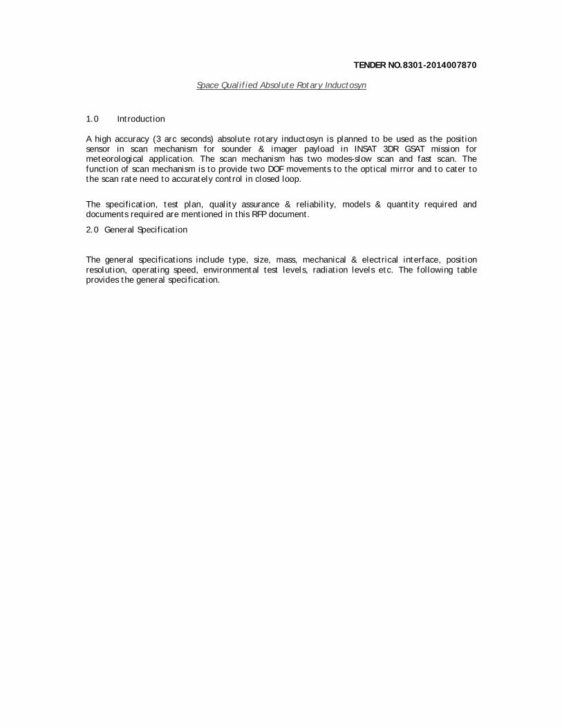
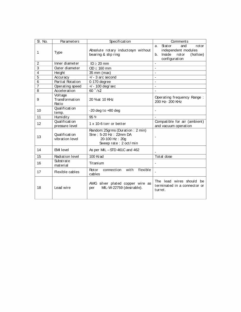
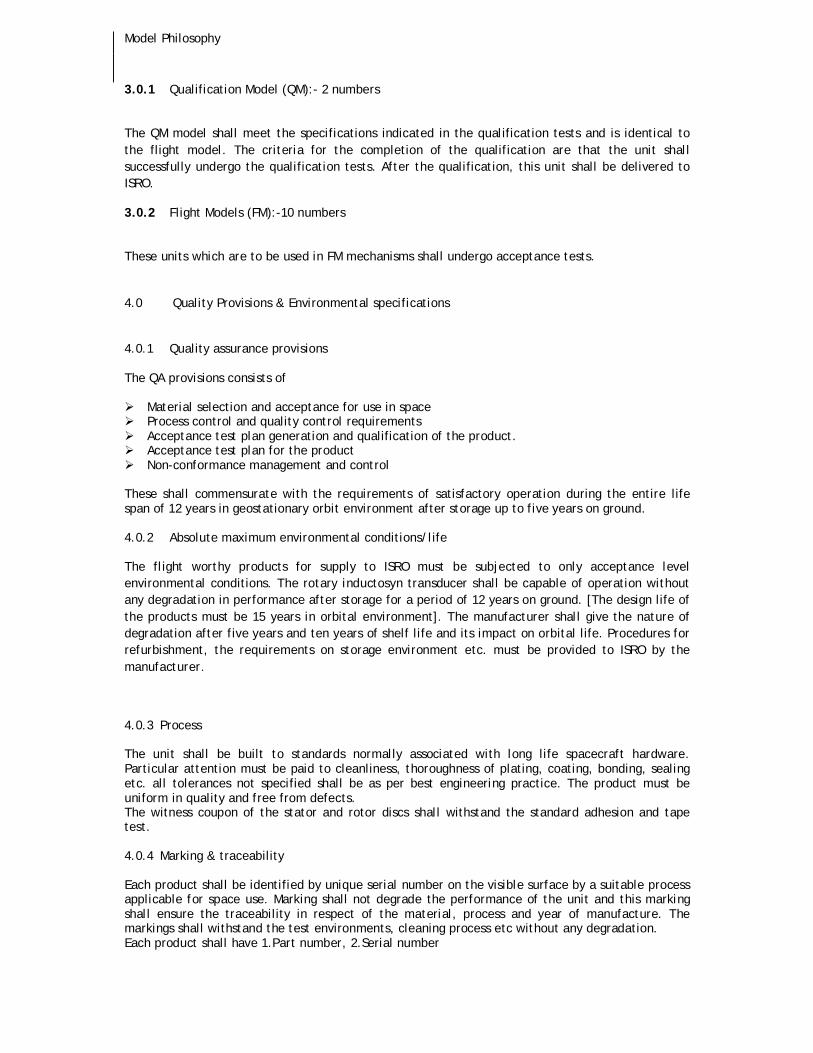
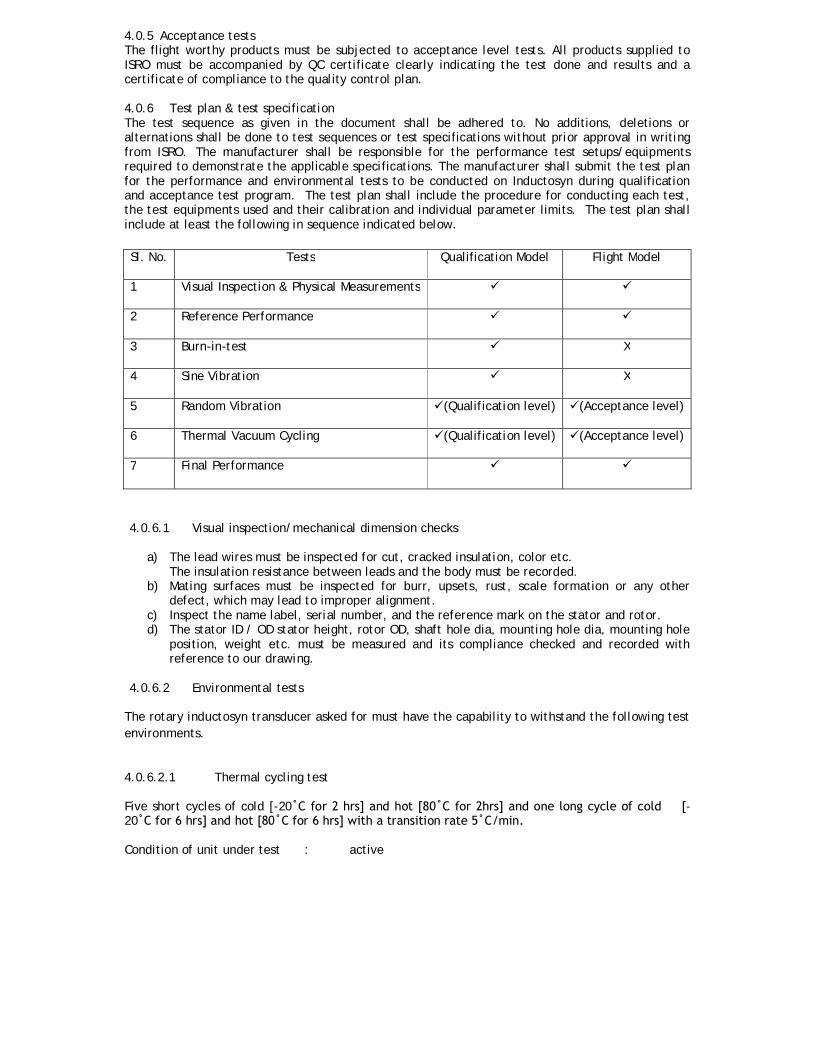
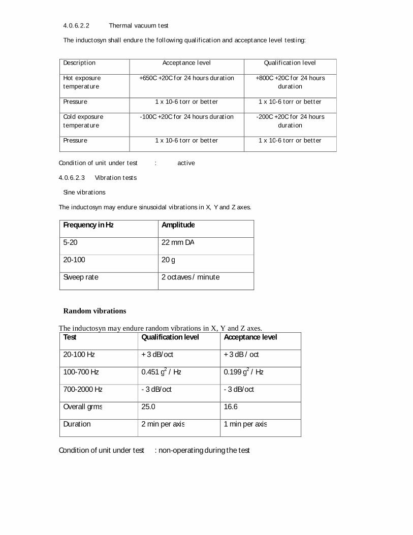
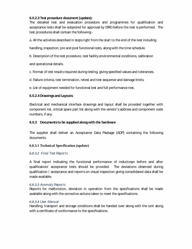
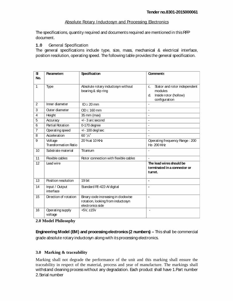
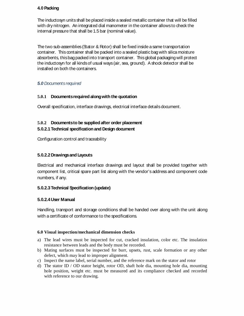
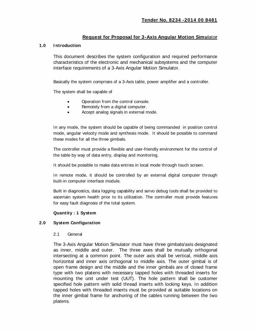
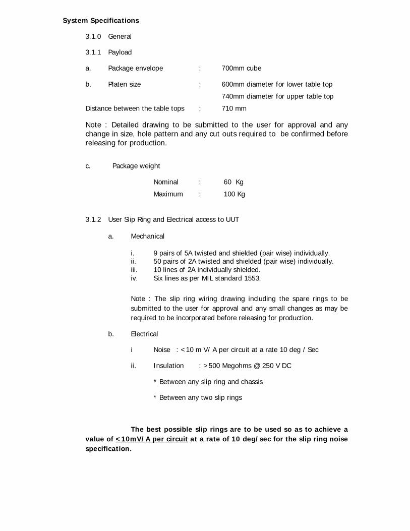
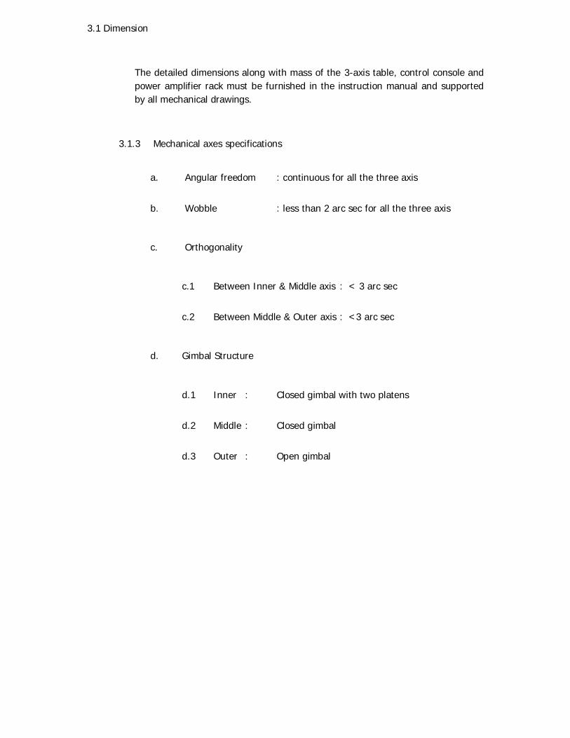
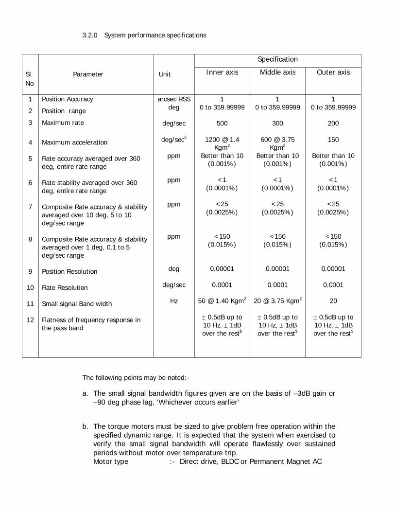
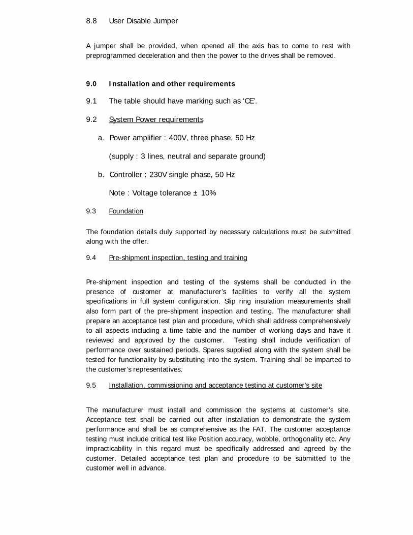
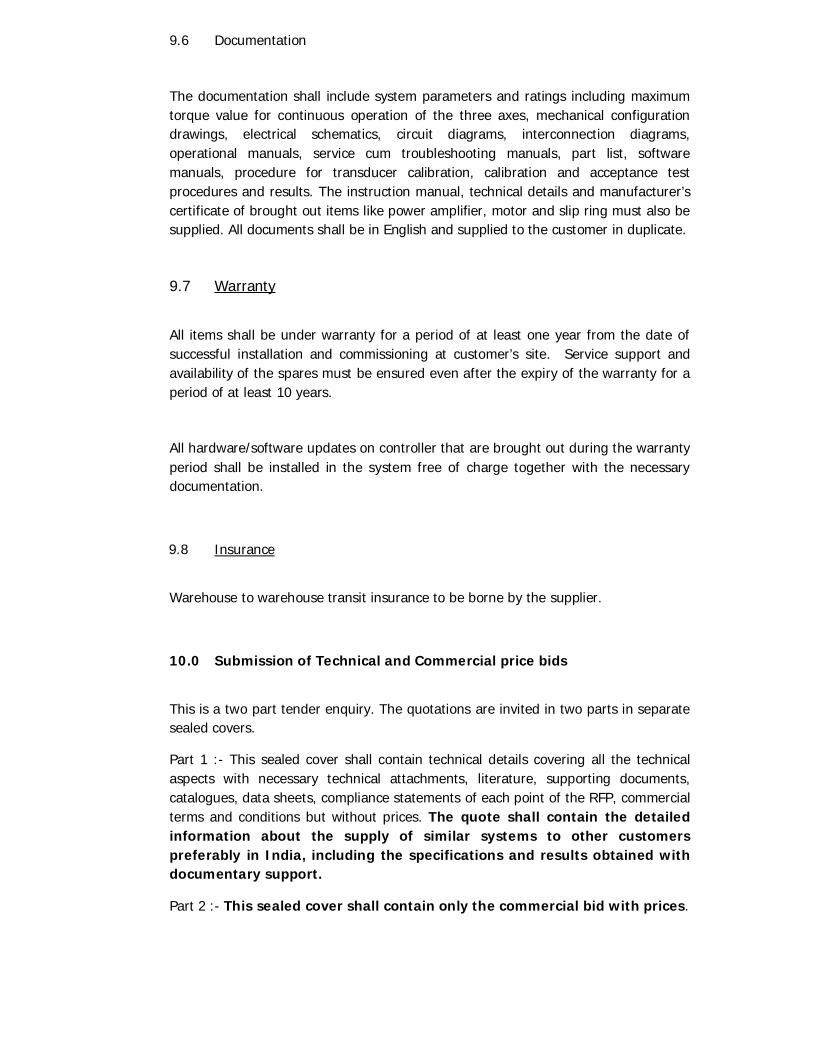
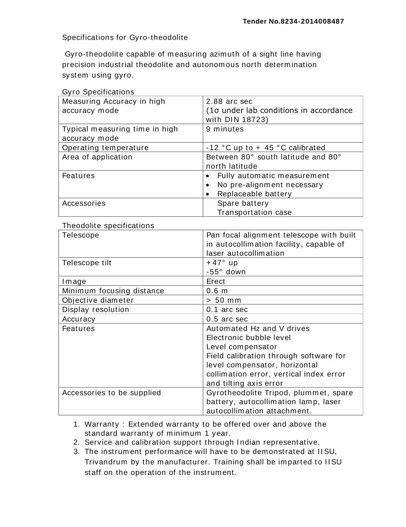
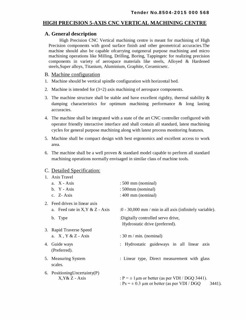
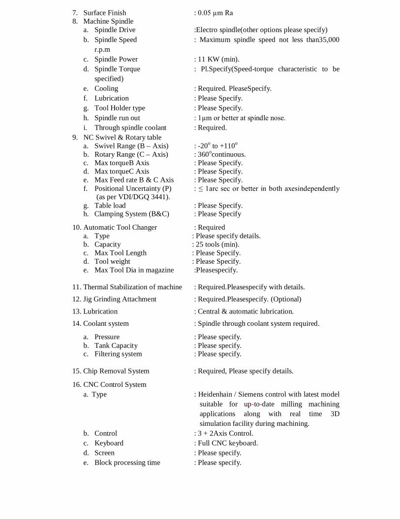
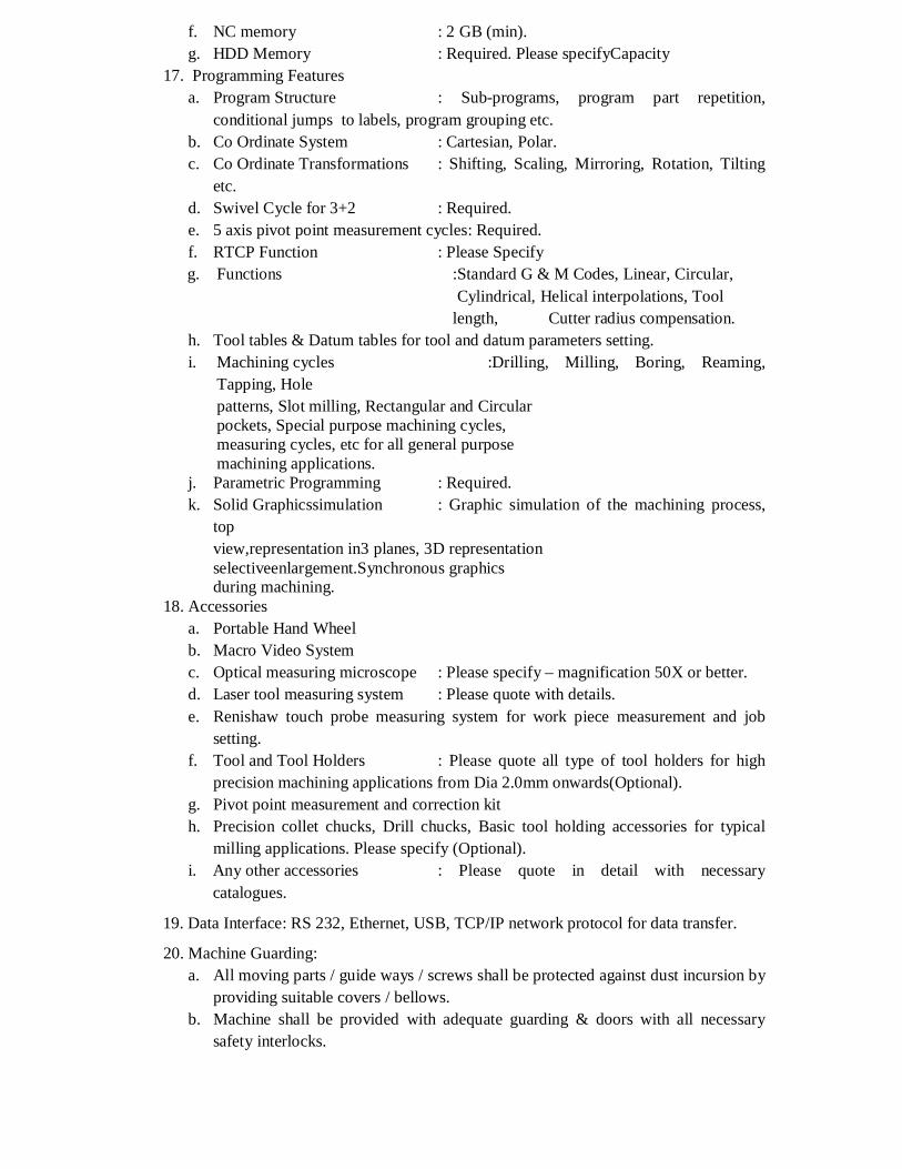
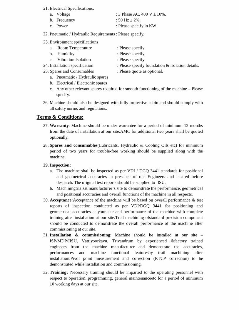
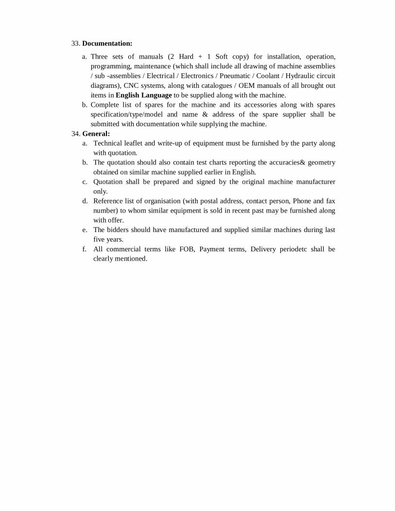
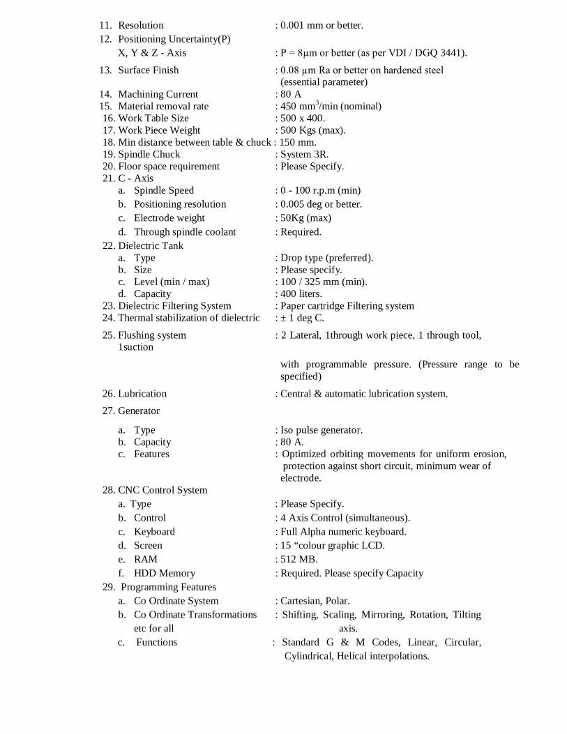
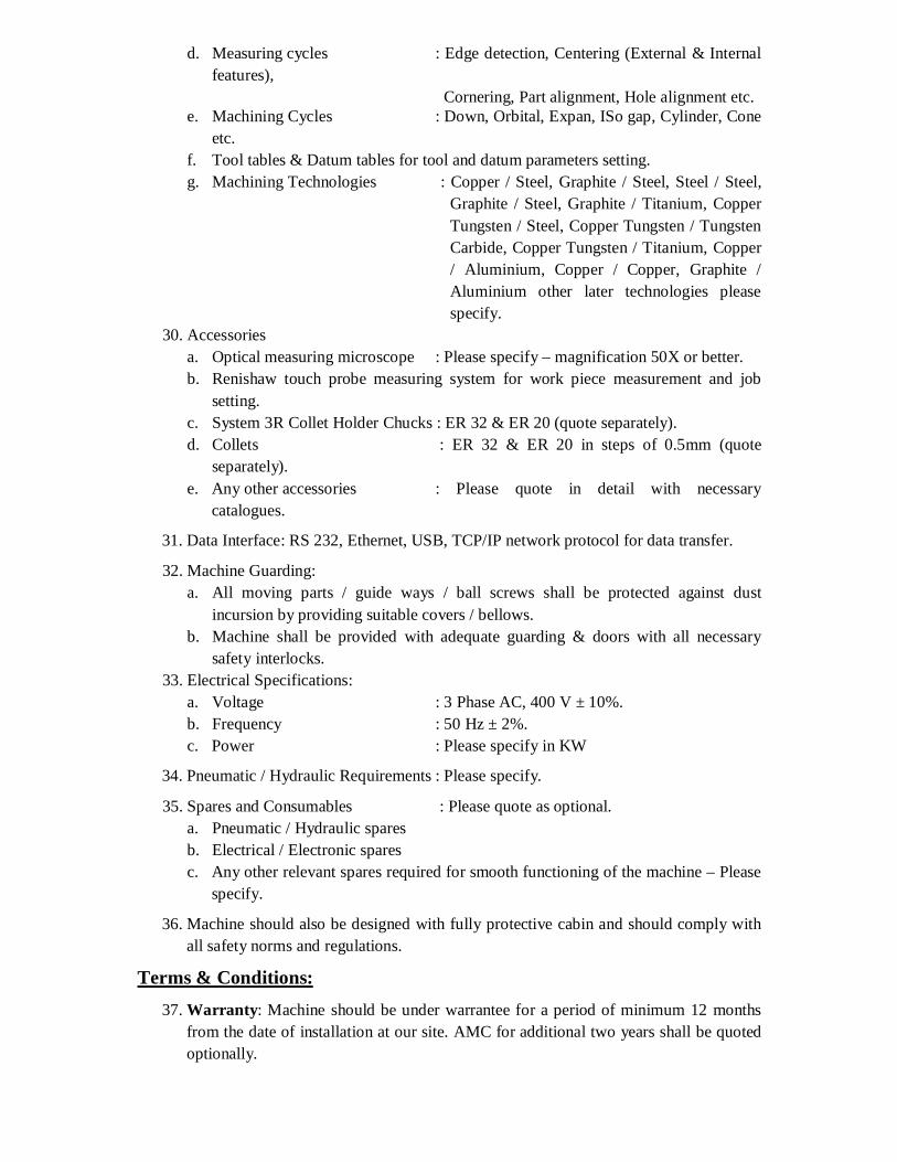
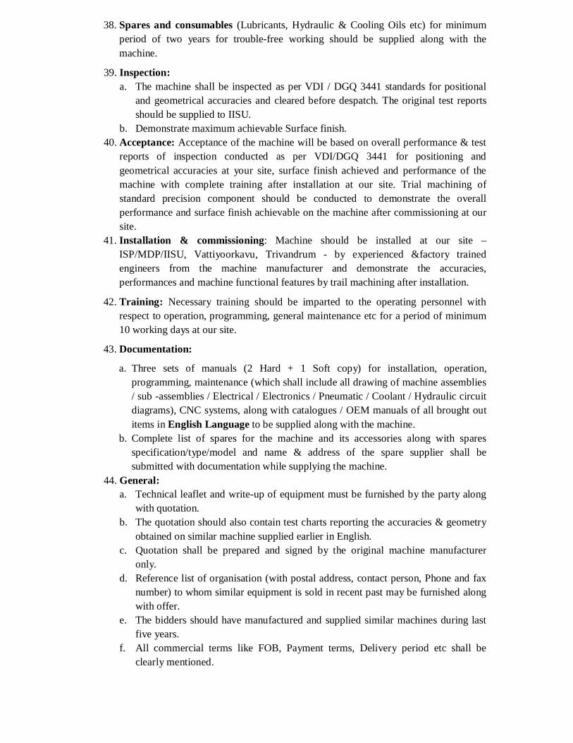
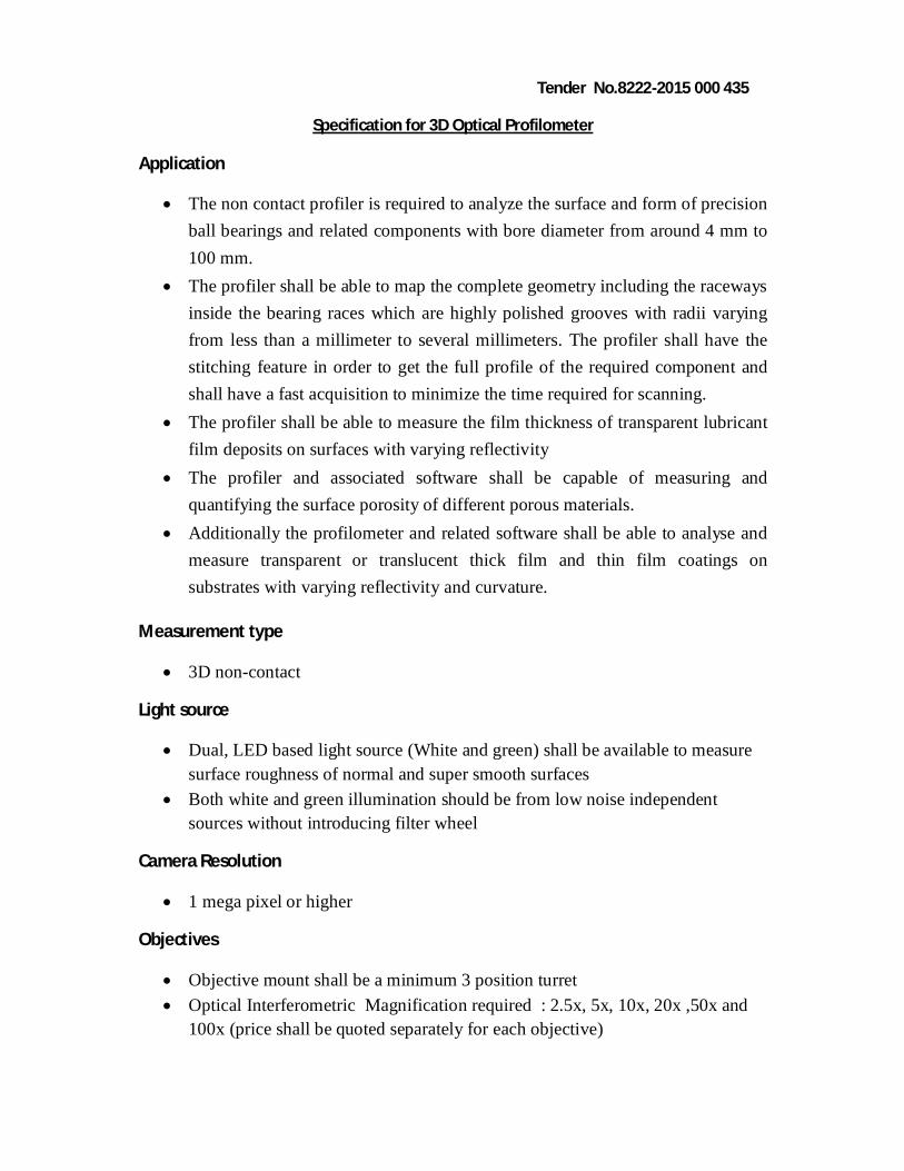
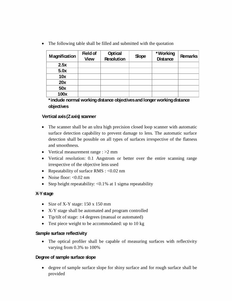
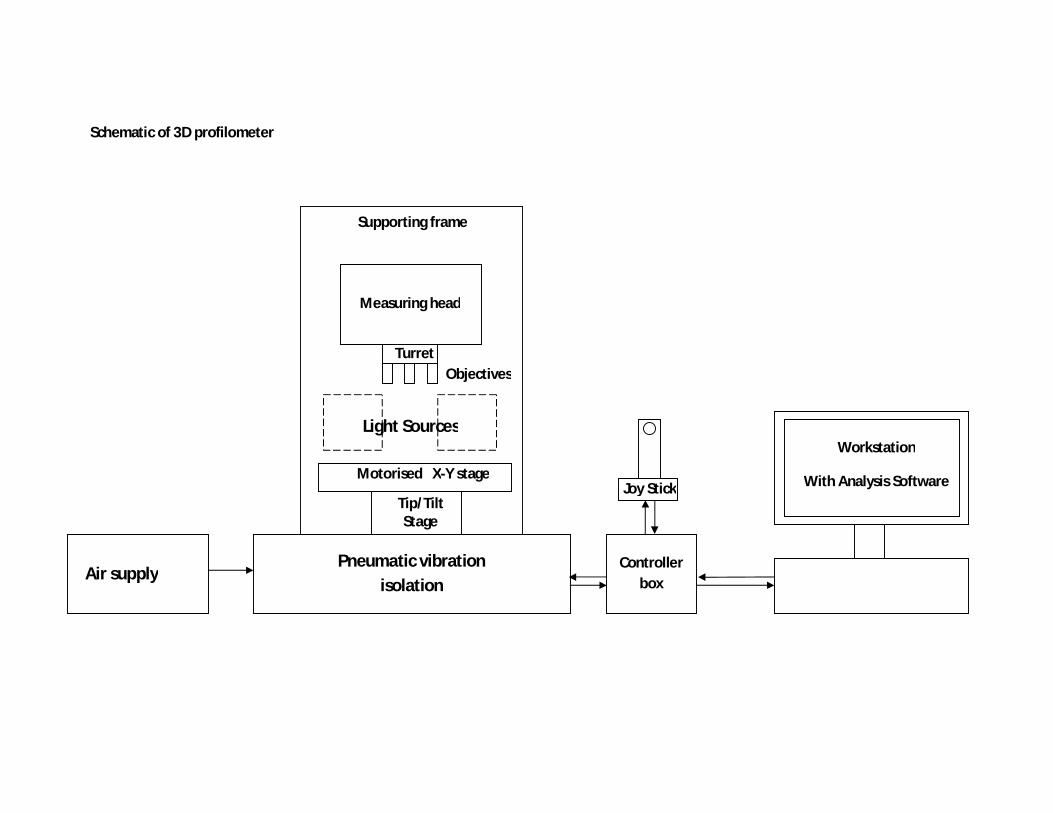
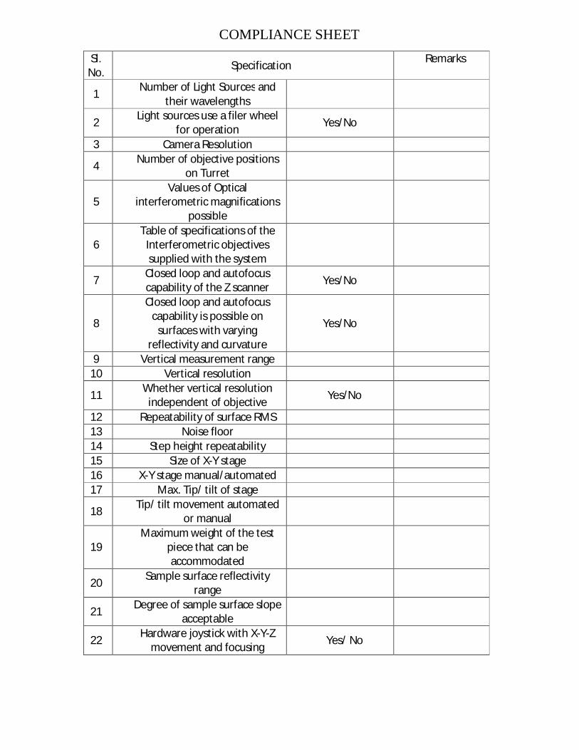
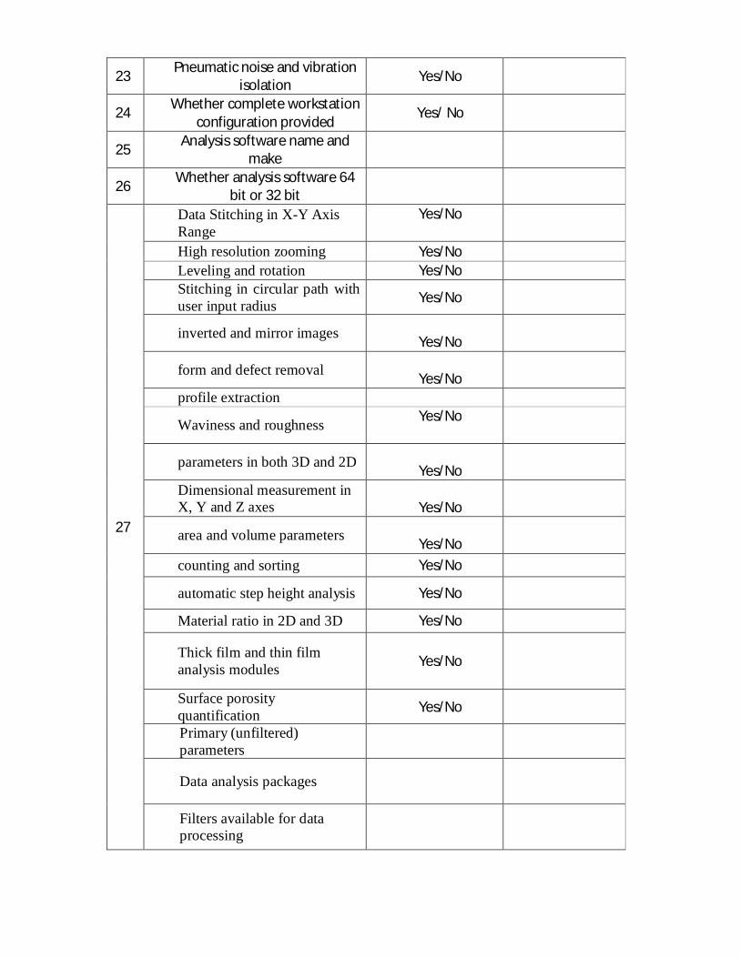
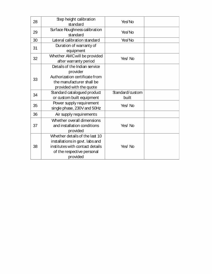
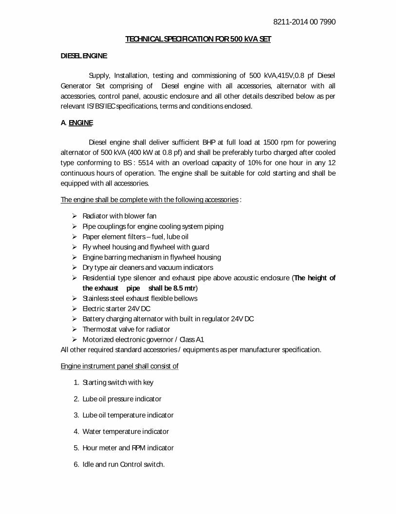
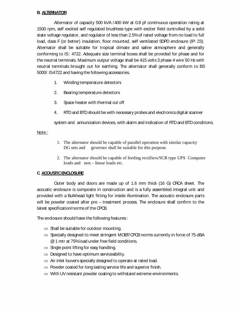